Course in FEM â ANSYS Workbench/CAD
Course in FEM â ANSYS Workbench/CAD
Course in FEM â ANSYS Workbench/CAD

You also want an ePaper? Increase the reach of your titles
YUMPU automatically turns print PDFs into web optimized ePapers that Google loves.
<strong>Course</strong> <strong>in</strong><strong>FEM</strong> – <strong>ANSYS</strong> <strong>Workbench</strong>/<strong>CAD</strong>3D Model<strong>in</strong>g<strong>FEM</strong> – <strong>ANSYS</strong> <strong>Workbench</strong>/<strong>CAD</strong>Computational Mechanics, AAU, Esbjerg
<strong>FEM</strong> - <strong>ANSYS</strong> Classic• Lecture 1 - Introduction:– Introduction to <strong>FEM</strong>– <strong>ANSYS</strong> Basics– Analysis phases– Geometric model<strong>in</strong>g– The first model: Beam model• Lecture 2 - Preprocessor:– Geometric model<strong>in</strong>g– Specification of Element type, Real Constants, Material, Mesh– Frame systems– Truss systems– Element tables• Lecture 3 - Loads:– Boundary conditions/constra<strong>in</strong>ts/supports– Loads– Mesh attributes, mesh<strong>in</strong>g– Sections• Lecture 4 – 2D plane models :– 2D Plane Solid systems– Geometric model<strong>in</strong>g– Postprocess<strong>in</strong>g• Lecture 5 – Analysis types:– Analysis types– Modal analysis– Buckl<strong>in</strong>g analysis<strong>FEM</strong> – <strong>ANSYS</strong> <strong>Workbench</strong>/<strong>CAD</strong>Computational Mechanics, AAU, Esbjerg3D Model<strong>in</strong>g 2
<strong>FEM</strong> - <strong>ANSYS</strong> <strong>Workbench</strong>/<strong>CAD</strong>• Lecture 6 – 3D Solids:– 3D solid models– Booleans– Mesh<strong>in</strong>g issues• Lecture 7 – 3D Model<strong>in</strong>g:– Operate– Import <strong>CAD</strong>– Advanced topics• Lecture 8 – Analysis types:– Analysis types– Postprocess<strong>in</strong>g– TimeHistProc• Lecture 9 – <strong>Workbench</strong> basics:– <strong>Workbench</strong> basics– Geometric model<strong>in</strong>g• Lecture 10 – <strong>Workbench</strong> analysis:– <strong>Workbench</strong> analysis types<strong>FEM</strong> – <strong>ANSYS</strong> <strong>Workbench</strong>/<strong>CAD</strong>Computational Mechanics, AAU, Esbjerg3D Model<strong>in</strong>g 3
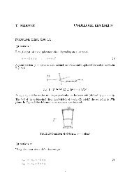
Example – I-beam (shell 3D)/PREP7K, ,,,,K, ,,,100,K, ,1000,,100,K, ,1000,,,K, ,1000,,-100,K, ,,,-100,K, ,,100,,K, ,,100,100,K, ,1000,100,100,K, ,1000,100,,K, ,1000,100,-100,K, ,,100,-100,LSTR, 1, 2LSTR, 2, 3LSTR, 3, 4LSTR, 4, 5LSTR, 5, 6LSTR, 6, 1LSTR, 1, 4LSTR, 7, 8LSTR, 8, 9LSTR, 9, 10LSTR, 10, 11LSTR, 11, 12LSTR, 12, 7LSTR, 7, 10LSTR, 7, 1LSTR, 10, 4AL,1,2,3,7AL,4,5,6,7AL,14,15,16,7AL,8,9,10,14AL,11,12,13,14CYL4,250,50,15<strong>FEM</strong> – <strong>ANSYS</strong> <strong>Workbench</strong>/<strong>CAD</strong>Computational Mechanics, AAU, Esbjerg3D Model<strong>in</strong>g 4
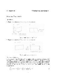
Example – I-beam (solid 3D)/PREP7K, ,0,0,0K, ,150,0,0K, ,150,15,0K, ,80,15,0K, ,80,285,0K, ,150,285,0K, ,150,300,0K, ,0,300,0K, ,0,285,0K, ,70,285,0K, ,70,15,0K, ,0,15,0LSTR, 1, 2LSTR, 2, 3LSTR, 3, 4LSTR, 4, 5LSTR, 5, 6LSTR, 6, 7LSTR, 7, 8LSTR, 8, 9LSTR, 9, 10LSTR, 10, 11LSTR, 11, 12LSTR, 12, 1LSTR, 11, 4LSTR, 10, 5AL,12,1,2,3,13,11AL,13,10,4,14AL,5,6,7,8,9,14!*VOFFST,1,100, ,!*VOFFST,2,100, ,!*VOFFST,3,100, ,K,200, 0,150,150,K,201,40,150,150,K,202,40,160,150,!CIRCLE,PCENT,RAD,PAXIS, PZERO, ARC, NSEGCIRCLE,200,25,201,202, ,<strong>FEM</strong> – <strong>ANSYS</strong> <strong>Workbench</strong>/<strong>CAD</strong>Computational Mechanics, AAU, Esbjerg3D Model<strong>in</strong>g 5
<strong>ANSYS</strong> - Import<strong>FEM</strong> – <strong>ANSYS</strong> <strong>Workbench</strong>/<strong>CAD</strong>Computational Mechanics, AAU, Esbjerg3D Model<strong>in</strong>g 6
<strong>ANSYS</strong> – Connectionproducts/Import<strong>FEM</strong> – <strong>ANSYS</strong> <strong>Workbench</strong>/<strong>CAD</strong>Computational Mechanics, AAU, Esbjerg3D Model<strong>in</strong>g 7
Import - ConsiderationsWhile Build<strong>in</strong>g the Model <strong>in</strong> the <strong>CAD</strong> System:• Observe <strong>ANSYS</strong> solid model<strong>in</strong>g procedures with regardto plann<strong>in</strong>g, symmetry, and the amount of detail neededfor a f<strong>in</strong>ite element analysis. For example, foraxisymmetric models, the <strong>ANSYS</strong> program requires thatthe global Y axis be the axis of rotation.<strong>FEM</strong> – <strong>ANSYS</strong> <strong>Workbench</strong>/<strong>CAD</strong>Computational Mechanics, AAU, Esbjerg3D Model<strong>in</strong>g 8
Import - ConsiderationsWhile Build<strong>in</strong>g the Model <strong>in</strong> the <strong>CAD</strong> System:• Avoid creat<strong>in</strong>g closed curves (that is, a l<strong>in</strong>e that startsand ends at the same po<strong>in</strong>t and closed surfaces (suchas a surface that starts and ends at the same edge).<strong>ANSYS</strong> can't store closed curves or closed surfaces (itrequires at least two keypo<strong>in</strong>ts). If a closed curve, closedsurface, or "trimmed" closed surface - def<strong>in</strong>ed by IGESentities 120 and 144 or 128 and 144 - is encounteredwhile read<strong>in</strong>g an IGES file, <strong>ANSYS</strong> will attempt to split it<strong>in</strong>to two or more entities.• As much as possible, write to the IGES file by data thatthe <strong>ANSYS</strong> program supports.<strong>FEM</strong> – <strong>ANSYS</strong> <strong>Workbench</strong>/<strong>CAD</strong>Computational Mechanics, AAU, Esbjerg3D Model<strong>in</strong>g 9
Import - ConsiderationsWhile Writ<strong>in</strong>g the IGES File From the <strong>CAD</strong> Program:• Transfer only the portion of the geometry required for theanalysis. A f<strong>in</strong>ite element analysis may not need asmuch detail as a <strong>CAD</strong> model requires.• For trimmed surface transfer, <strong>in</strong>clude global XYZ dataalong with UV data <strong>in</strong> the IGES file.<strong>FEM</strong> – <strong>ANSYS</strong> <strong>Workbench</strong>/<strong>CAD</strong>Computational Mechanics, AAU, Esbjerg3D Model<strong>in</strong>g 10
Import - ConsiderationsWhile Writ<strong>in</strong>g the IGES File From the <strong>CAD</strong> Program:• If the model to be analyzed is very large, use the <strong>CAD</strong> program'sselection capabilities to create several IGES files, each conta<strong>in</strong><strong>in</strong>g aportion of the model. The <strong>ANSYS</strong> program will use the nextavailable entity number as each file is read. You can then use thePREP7 merge feature (NUMMRG command or menu path Ma<strong>in</strong>Menu> Preprocessor> Number<strong>in</strong>g Ctrls> Merge Items) to mergeco<strong>in</strong>cident entities.• Write the IGES file <strong>in</strong> ASCII format, with 80 characters per record.• For the Pro/ENGINEER program, use these additional guidel<strong>in</strong>es:– Set the Config.pro option "iges_out_trim_xyz" to "yes."– Set the accuracy to 1E-6 and regenerate the model.<strong>FEM</strong> – <strong>ANSYS</strong> <strong>Workbench</strong>/<strong>CAD</strong>Computational Mechanics, AAU, Esbjerg3D Model<strong>in</strong>g 11
Import - ConsiderationsWhile Read<strong>in</strong>g the IGES File <strong>in</strong>to <strong>ANSYS</strong>:• Pay attention to the messages issued by the <strong>ANSYS</strong>program. Warn<strong>in</strong>g messages give details such as IGESentities not transferred and the correspond<strong>in</strong>g <strong>ANSYS</strong>entity numbers.• If any IGES entities were not transferred, reconstructthem us<strong>in</strong>g <strong>ANSYS</strong> solid model<strong>in</strong>g commands. TheSMOOTH IGES filter is capable of read<strong>in</strong>g <strong>in</strong> any rationalB-spl<strong>in</strong>e curve entity (type 126), or rational B-spl<strong>in</strong>esurface entity (type 128) with a degree less than or equalto 20. Attempts to read <strong>in</strong> B-spl<strong>in</strong>e curve or surfaceentities of degree higher than 20 may result <strong>in</strong> errormessages.<strong>FEM</strong> – <strong>ANSYS</strong> <strong>Workbench</strong>/<strong>CAD</strong>Computational Mechanics, AAU, Esbjerg3D Model<strong>in</strong>g 12
Import - ConsiderationsWhile Read<strong>in</strong>g the IGES File <strong>in</strong>to <strong>ANSYS</strong>:• Duplicate l<strong>in</strong>es and keypo<strong>in</strong>ts are possible when transferr<strong>in</strong>g amodel <strong>in</strong> from an IGES file. This often happens with <strong>CAD</strong> modelsdue to the tolerances and practices that they were created with. Yousometimes need to "clean up" these solid models with <strong>ANSYS</strong>commands that merge duplicate entities together (NUMMRGcommand or menu path Ma<strong>in</strong> Menu> Preprocessor> Number<strong>in</strong>gCtrls> Merge Items).• Merg<strong>in</strong>g is done automatically when an IGES file is read <strong>in</strong>to<strong>ANSYS</strong> [IGESIN] <strong>in</strong> AUX15. Default tolerances are used todeterm<strong>in</strong>e if keypo<strong>in</strong>ts should be merged together <strong>in</strong>to a s<strong>in</strong>glekeypo<strong>in</strong>t. Sometimes the default tolerances are not adequate andmust be adjusted.<strong>FEM</strong> – <strong>ANSYS</strong> <strong>Workbench</strong>/<strong>CAD</strong>Computational Mechanics, AAU, Esbjerg3D Model<strong>in</strong>g 13
Import - ConsiderationsWhile Writ<strong>in</strong>g an IGES File from <strong>ANSYS</strong>:• Set the system of units [/UNITS] before writ<strong>in</strong>g the IGES file. This<strong>in</strong>formation is captured on the IGES file and is read by manyprograms that read IGES files. (You cannot access the /UNITScommand directly <strong>in</strong> the GUI.)• Select all lower level solid model<strong>in</strong>g entities before writ<strong>in</strong>g the file(ALLSEL,BELOW,ALL or menu path Utility Menu> Select>Everyth<strong>in</strong>g Below).• If you wish to write out a portion of your model, select only thoseentities (areas) to be written and all correspond<strong>in</strong>g lower levelentities (l<strong>in</strong>es and keypo<strong>in</strong>ts). Then unselect any higher level entities(volumes) before writ<strong>in</strong>g the file.<strong>FEM</strong> – <strong>ANSYS</strong> <strong>Workbench</strong>/<strong>CAD</strong>Computational Mechanics, AAU, Esbjerg3D Model<strong>in</strong>g 14
Import - .SAT fileImport us<strong>in</strong>g the <strong>ANSYS</strong> GUI• Select File> Import> SAT. The <strong>ANSYS</strong> Connection for SAT dialog box appears, asshown below.• Select the desired SAT file. In addition to the file name, location and type options,modify the follow<strong>in</strong>g values as necessary.– Allow Defeatur<strong>in</strong>g - Select this button to store the model <strong>in</strong> the solid database format so thatit can be defeatured after import. The default is to store the model <strong>in</strong> neutral database format,which restricts defeatur<strong>in</strong>g after import.– Geometry Type - Import the file as• Solids Only - imported as <strong>ANSYS</strong> volumes (default).• SurfacesOnly - Imported as <strong>ANSYS</strong> areas.• Wireframe Only - Imported as <strong>ANSYS</strong> l<strong>in</strong>es.• All - Import all entities; use this when the file conta<strong>in</strong>s multiple entity types.• Click OK.Note• If your imported model conta<strong>in</strong>s multiple volumes, Boolean operators are available tofurther process your geometry.<strong>FEM</strong> – <strong>ANSYS</strong> <strong>Workbench</strong>/<strong>CAD</strong>Computational Mechanics, AAU, Esbjerg3D Model<strong>in</strong>g 15
Import - .SAT fileProblems Specific to <strong>ANSYS</strong> Connection for SAT• Listed below are several problems you may encounter when runn<strong>in</strong>g<strong>ANSYS</strong> Connection for SAT. For further troubleshoot<strong>in</strong>g <strong>in</strong>formation, seeAppendix B.• If a part fails to convert <strong>in</strong>to <strong>ANSYS</strong>, exam<strong>in</strong>e filename.sat_log andfilename.ans_log. Both files are located <strong>in</strong> the work<strong>in</strong>g directory. Thefilename.sat_log file conta<strong>in</strong>s warn<strong>in</strong>gs and errors generated dur<strong>in</strong>g theconversion that relate to problems <strong>in</strong> the file itself. The filename.ans_log fileconta<strong>in</strong>s warn<strong>in</strong>gs and errors that relate to build<strong>in</strong>g the model <strong>in</strong> <strong>ANSYS</strong>.• If a model is sensitive to tolerance, shapes may not be created properly,which can lead to poorly transferred areas. If you f<strong>in</strong>d this problem with amodel, reimport it us<strong>in</strong>g the follow<strong>in</strong>g steps:• Import the file us<strong>in</strong>g the default format (neutral).• Enter the follow<strong>in</strong>g command <strong>in</strong> the <strong>ANSYS</strong> Input w<strong>in</strong>dow:– XANF,filename.aaa,-tolerance_1.0e-6where filename.aaa is the name of the fileyou are work<strong>in</strong>g with<strong>FEM</strong> – <strong>ANSYS</strong> <strong>Workbench</strong>/<strong>CAD</strong>Computational Mechanics, AAU, Esbjerg3D Model<strong>in</strong>g 16
Import - .SAT fileThe follow<strong>in</strong>g problem may occur on UNIX systems: The softwaremay not come up if the required shared library(ansys_<strong>in</strong>c/ansys81/lib//libac4.so) is not present or if thepath names listed <strong>in</strong> this file are <strong>in</strong>correct. Check for proper<strong>in</strong>stallation.The follow<strong>in</strong>g problems may occur on W<strong>in</strong>dows systems: A syserror may be displayed if the executable is <strong>in</strong> the wrong directory orif the required shared libraries are miss<strong>in</strong>g. Check for proper<strong>in</strong>stallation.• ***Warn<strong>in</strong>g: <strong>ANSYS</strong> environment variables: <strong>ANSYS</strong>81_DIR and/or<strong>ANSYS</strong>81_SYSDIR are not set.• ***ERROR: <strong>ANSYS</strong> Connection for SAT directory structure is notset. Unable to f<strong>in</strong>d the Connection executable.• Either the <strong>ANSYS</strong>81_DIR or the <strong>ANSYS</strong>81_SYSDIR variable needsto be set.<strong>FEM</strong> – <strong>ANSYS</strong> <strong>Workbench</strong>/<strong>CAD</strong>Computational Mechanics, AAU, Esbjerg3D Model<strong>in</strong>g 17
Import - Heal<strong>in</strong>gThe Heal<strong>in</strong>g Module• This section exam<strong>in</strong>es how to “heal” a model that you haveimported <strong>in</strong>to <strong>ANSYS</strong> via either the <strong>ANSYS</strong> GUI or the ~HEALcommand.• Heal<strong>in</strong>g is the process of prepar<strong>in</strong>g <strong>CAD</strong> data to be read <strong>in</strong>to<strong>ANSYS</strong>. You can use heal<strong>in</strong>g with exist<strong>in</strong>g <strong>ANSYS</strong> Connectionproducts, as well as with other imports supported by the <strong>ANSYS</strong>Automatic Geometry Heal<strong>in</strong>g Module (AGHM). If you have alicense for an <strong>ANSYS</strong> connection and an AGHM import licensefor the same type of data, the AGHM option will be used to readthe data. In either case, an .anf file is created.• Heal<strong>in</strong>g via the AGHM is a module available through <strong>CAD</strong>fix.Note• The images shown <strong>in</strong> this section may vary slightly compared towhat displays on your system. However the functionality is thesame.<strong>FEM</strong> – <strong>ANSYS</strong> <strong>Workbench</strong>/<strong>CAD</strong>Computational Mechanics, AAU, Esbjerg3D Model<strong>in</strong>g 18