Rotation Correction Plates 1.5 and 2.0. Reposition ... - Osteosyntese
Rotation Correction Plates 1.5 and 2.0. Reposition ... - Osteosyntese
Rotation Correction Plates 1.5 and 2.0. Reposition ... - Osteosyntese
- No tags were found...
Create successful ePaper yourself
Turn your PDF publications into a flip-book with our unique Google optimized e-Paper software.
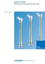
<strong>Rotation</strong> <strong>Correction</strong> <strong>Plates</strong> <strong>1.5</strong> <strong>and</strong> <strong>2.0.</strong><strong>Reposition</strong> plates for fractures<strong>and</strong> osteotomies at the metacarpals <strong>and</strong>phalanges.Anatomically precontouredMinimal irritation of ligaments <strong>and</strong> soft tissue thanks to a flatplate <strong>and</strong> screw profile, rounded edges <strong>and</strong> polished surfaces.Transversally elongated holesAn elongated hole transversal to the axis of the plate shaftallows intraoperative inspection of the reduction <strong>and</strong> allowsthe surgeon to correct the rotational axis of the bone if necessaryAngular stability 2.0 mm locking screws can be used in the head. Cortex orlocking screws can be used in the shaft, depending on theplate size.The design of the plate head makes it easy to adjust to theanatomy of the condyles.Two shaft lengthsTwo different shaft lengths of the plates allow fragment-specifictreatment of fractures of the metacarpals <strong>and</strong> proximalphalanges.2 Synthes <strong>Rotation</strong> <strong>Correction</strong> <strong>Plates</strong> <strong>1.5</strong> <strong>and</strong> 2.0 Technique Guide
Indications <strong>and</strong> ContraindicationsIndications1.All fractures of the phalanges <strong>and</strong> metacarpals, where theexact reposition is difficult or where a rotational error caneasily occur.– subcapital fractures of the metacarpals (in particular impactedcompression fractures)– transverse fractures– short oblique fractures– comminuted fractures– defect fractures (circular saw injuries)– amputation injuries to the fingers (with primary shortening)– Winterstein fracture, Rol<strong>and</strong>o fracture2.Corrective osteotomies for fractures of the phalanges ormetacarpals that have healed with axial errors <strong>and</strong>/or rationalerrors.In the case of metaphyseal fractures, comminuted fractures<strong>and</strong> osteoporotic bone, the clinical results can be improvedby the angular-stable screw/plate connection.ContraindicationsEasily reduced oblique or spiral fractures that can be precisely<strong>and</strong> firmly stabilized using screw osteosynthesis.4 Synthes <strong>Rotation</strong> <strong>Correction</strong> <strong>Plates</strong> <strong>1.5</strong> <strong>and</strong> 2.0 Technique Guide
Case StudiesCase 1Subcapital comminuted fracture of the 2nd metacarpalbone42-year-old man, fall from bike.Compressed fracture of the metacarpal head with 4 mmshortening <strong>and</strong> 20° ulnar malangulation. Instable, subcapitalimpacted compression zone with bony collateral ligamenttears. Primary treatment with plaster splint with only 30°flexion of the metacarpophalangeal joints.Intraoperative far distal angular stable fixation of the head,compensating for errors in the length <strong>and</strong> rotation. Immediateactive exercise treatment.Preoperative, dorsopalmar <strong>and</strong> obliquePostoperative, dorsopalmar <strong>and</strong> lateralSynthes 5
Case studiesCase 2Pseudoarthrosis of the 4th metacarpal bone followingfailed screw osteosynthesisPreoperative withpseudoarthrosis <strong>and</strong> 6 mmshortening, dorsopalmar32-year-old woman with screw osteosynthis treated elsewhere.The patient presented with pain, swelling <strong>and</strong> rotationalerror 6 months after the primary treatment.Intraoperatively, an anatomical reposition is no longer possible.Angularly stable fixation close to joint. Proximal with cortexscrews. Immediate active exercise treatment.Postoperative followingcompensation of length <strong>and</strong>rotational error, dorsopalmarPostoperative, laterale6 Synthes <strong>Rotation</strong> <strong>Correction</strong> <strong>Plates</strong> <strong>1.5</strong> <strong>and</strong> 2.0 Technique Guide
ImplantationIf fractures to the metacarpals or the proximal phalanges aremisaligned, the function of the h<strong>and</strong> can be severely affected.Especially rotational misalignments are problematicbecause of crossing <strong>and</strong> scissoring digits whenever fullflexion of the fingers to a fist is attempted. Even minor rotationalerrors in the fingers frequently have to be surgicallycorrected after a fracture has healed.For metacarpal fractures <strong>and</strong> fractures of the proximal phalanges,optimal recovery of h<strong>and</strong> function includes the meticulousrestoration of alignment, length <strong>and</strong> rotation of digits<strong>and</strong> metacarpals. A careful approach needs to be chosen inorder not to further compromise the soft tissue situationwhich again requires proper reconstruction. The fixation hasto be stable enough in order to facilitate immediate active<strong>and</strong> passive finger exercises.ApproachesFor the metacarpal bones, the 2nd ray may be approacheddorso-radially above the palpable bone, the 5th ray dorsoulnarabove the bone, <strong>and</strong> the 3rd <strong>and</strong> 4th metacarpal eitherdirectly above the respective bone or between both of themwhen two adjacent bones are affected.The proximal phalanges are usually approached through themedian line of the respective bone.Synthes 7
3Bending the plate head <strong>and</strong> plate shaft1Instruments329.921 Bending Pin for LCP <strong>Plates</strong> 2.0, with thread347.901 Pliers, flat-nosed, pointed,for <strong>Plates</strong> 1.0 to 2.4If necessary, bend the plate to suit the anatomical conditions.1. Preferably bend the plate head with two bending pins.2. Ensure that the shaft is bent between the combinationholes, as it will otherwise be difficult to insert thelocking screws. We recommend using two pairs of pliers.Note: The design of the plate holes allows a certain degreeof deformation tolerance. Locking is, however, not as efficientif the thread holes are significantly deformed. For thisreason the surgeon should avoid bending the plate by insertingthe bending pins into a combination hole.2Warning: The plate should ideally not be cut. The sharp cutedges can damage the radiodorsal tendons <strong>and</strong> can irritatethe soft tissue.Synthes 9
Implantation4Position platePosition the plate near the joint. The transverse elongatedhole must be on the far side of the fracture on a section ofbone that is intact. First fix the head or condyle region nearthe joint using two 2.0 mm locking screws to support thejoint surfaces <strong>and</strong> to prevent repositioning loss.Please refer to page 19 for information on inserting the lockingscrews.Caution: Ensure that there is no dorsal or palmar damage tothe cartilaginous joint surfaces by either the plate or thescrews <strong>and</strong> that the collateral ligaments are not unintentionallyfixed.Tip: If the axis <strong>and</strong> the length of the bone are not yet exactlyset the plate can be fixed to the bone with plate holdingforceps <strong>and</strong> the Kirschner wire can be removed. The length<strong>and</strong> the axis of the bone can now be corrected using theplate <strong>and</strong> the plate holding forceps. The Kirschner wire canbe left in place if it is already fixing the exact position <strong>and</strong> isnot blocking the transverse elongated hole.10 Synthes <strong>Rotation</strong> <strong>Correction</strong> <strong>Plates</strong> <strong>1.5</strong> <strong>and</strong> 2.0 Technique Guide
5Insert screw into elongated holeInsert <strong>and</strong> carefully tighten a st<strong>and</strong>ard cortex screw in theexact position in the central part of the transverse elongatedhole. Either select <strong>1.5</strong> mm or 2.0 mm cortex screws dependingon the plate size.Please refer to page 16 for information on inserting the cortexscrews.Synthes 11
Implantation6Check result of repositioningProp up the forearm with the elbow supported on the operatingtable while the wrist is at maximum flexion. In thisposition the finger joints are straightened by the tenodesiseffect of the extensor tendons. Check the axis <strong>and</strong> the rotationof the fingers.Place the wrist passively in the maximum extension positionwhile compressing the forearm anteriorly in the middle of itsshaft. In this position, the tenodesis effect of the flexor tendons<strong>and</strong> the compression of the forearm muscles will causethe fingers to flex to nearly form a fist. This way, rotationalerrors of the digits are easily detected.Check the repositioning result with thewrist at maximum extensionReleasing <strong>and</strong> tightening the cortex screw in the transverselongitudinal hole ensures that the optimum position of thefinger can be identifiedSet the optimum finger positions by releasing <strong>and</strong> tighteningthe elongated hole screw12 Synthes <strong>Rotation</strong> <strong>Correction</strong> <strong>Plates</strong> <strong>1.5</strong> <strong>and</strong> 2.0 Technique Guide
7Final fixationFix a screw in the optimum position distal or proximal to thetransverse elongated hole. The other holes may remainfree or can be fitted with additional cortex screws. The holeabove the fracture line generally remains free.Please refer to page 16 for information on inserting the cortexscrews.Note: For 2.0 correction plates either 2.0 mm lockingscrews or 2.0 mm cortex screws may be used in the shaft.Only <strong>1.5</strong> mm cortex screws are used in the stem of <strong>1.5</strong>/2.0correction plates.The synovial sheath above the plate should be closed with aresorbable 6/0 suture as far as possible. The extensor tendonis readapted in the median line with a resorbable 5/0 suture.After fitting a «size 6» Redon Drain, close the skin with asingle button suture <strong>and</strong> then apply an elasto-compressiveb<strong>and</strong>age.Synthes 13
Implantation8Postoperative treatmentPost-operatively, the h<strong>and</strong> is consequently put upright. Removethe Redon Drain one day post-operatively. Subsequently,active <strong>and</strong> passive finger exercises should be startedwith the aim of full extension <strong>and</strong> flexion within a week.14 Synthes <strong>Rotation</strong> <strong>Correction</strong> <strong>Plates</strong> <strong>1.5</strong> <strong>and</strong> 2.0 Technique Guide
Implant removalTo remove locking screws, first unlock all screws from theplate; then remove the screws completely from the bone.This prevents rotation of the plate when removing the lastlocking screw.Synthes 15
Insert cortex screwsInstruments for correction plates 2.0311.012 H<strong>and</strong>le, medium,with Mini Quick Coupling314.676 Screwdriver Shaft Stardrive 2.0,with Holding Sleeve, length 66 mm,for Mini Quick Coupling323.200 Universal Drill Guide 2.0319.005 Depth Gauge for Screws 2.0 <strong>and</strong>2.4 mm, measuring range up to 40 mm310.507 Drill Bit <strong>1.5</strong> mm with marking,length 96/82 mm, 2-flute,for Mini Quick Coupling513.140 Drill Bit 2.0 mm, length 67/55 mm,2-flute, for Mini Quick CouplingAdditional instruments required forcorrection plates <strong>1.5</strong>/2.0314.667 Screwdriver Shaft <strong>1.5</strong>, cruciform,with Holding Sleeve, length 66 mm,with Mini Quick Coupling312.140 Double Drill Guide <strong>1.5</strong>/1.1319.003 Depth Gauge for Screws 1.3 to <strong>1.5</strong> mm,measuring range up to 24 mm513.030 Drill Bit 1.1 mm, length 45/33 mm,2-flute, for Mini Quick Coupling16 Synthes <strong>Rotation</strong> <strong>Correction</strong> <strong>Plates</strong> <strong>1.5</strong> <strong>and</strong> 2.0 Technique Guide
1Predrill screw holePredrill the holes for the combination screws either neutrally(support) or eccentrically (compression) into the non-threadbearing part of the combination hole using the universal drillguide that is appropriate for the screw diameter.Cortex screw 2.0 mm: Use the <strong>1.5</strong> mm drill bit for athreaded hole <strong>and</strong> the 2.0 mm drill bit for a gliding hole.Note: For rotation correction plates <strong>1.5</strong>/2.0 use the universaldrill guide <strong>1.5</strong>/1.1 for <strong>1.5</strong> mm cortex screws. Use the 1.1 mm drill bit for the threaded hole <strong>and</strong> a <strong>1.5</strong> mmdrill bit for the gliding hole.Neutral pre-drillingEccentric pre-drilling2Determine screw lengthDetermine the screw length using the 2.0 mm depthgauge.Note: Use the <strong>1.5</strong> mm depth gauge for <strong>1.5</strong> mm cortexscrews.Synthes 17
Insert cortex screws3Pick up screwPick up the selected 2.0 mm cortex screw with the screwdrivershaft Stardrive 2.0 with holding sleeve <strong>and</strong> the correspondingh<strong>and</strong>le.Notes– A self-holding screwdriver (such as 313.842/313.843)Stardrive 2.0 can also be used.– If using <strong>1.5</strong> mm cortex screws the cruciform screwdrivershaft with holding sleeve should be used.4Insert self-tapping st<strong>and</strong>ard screwsInsert the self-tapping st<strong>and</strong>ard screws with the screwdriver.18 Synthes <strong>Rotation</strong> <strong>Correction</strong> <strong>Plates</strong> <strong>1.5</strong> <strong>and</strong> 2.0 Technique Guide
Insert locking screwInstruments311.012 H<strong>and</strong>le, medium,with Mini Quick Coupling314.676 Screwdriver Shaft Stardrive 2.0,with Holding Sleeve, length 66 mm,for Mini Quick Coupling323.034 LCP Drill Sleeve 2.0, with Scale,for Drill Bits <strong>1.5</strong> mm with marking319.005 Depth Gauge for Screws 2.0 <strong>and</strong>2.4 mm, measuring range up to 40 mm310.507 Drill Bit <strong>1.5</strong> mm with marking,length 96/82 mm, 2-flute,for Mini Quick Coupling1Use LCP drill sleeveScrew <strong>and</strong> lock the drill sleeve vertically into the thread ofthe selected hole.Synthes 19
Insert locking screw2Predrill screw holePredrill the screw hole with the <strong>1.5</strong> mm drill bit throughthe drill sleeve for locking screws 2.0 mm to the requireddepth <strong>and</strong> then read the screw length directly from the drillsleeve scale.3Determine screw length (optional)Determine the screw length using the 2.0 mm depthgauge for screws, as shown on page 17.20 Synthes <strong>Rotation</strong> <strong>Correction</strong> <strong>Plates</strong> <strong>1.5</strong> <strong>and</strong> 2.0 Technique Guide
4Pick up screwPick up the selected screw with the screwdriver shaftStardrive with holding sleeve <strong>and</strong> the corresponding h<strong>and</strong>le.Note: A self-holding screwdriver (such as 313.842/313.843)Stardrive 2.0 can also be used.5Insert self-tapping locking screwsManually insert the locking screws with the screwdriver.Carefully tighten the locking screw, as excessive force is notnecessary to effectively lock the screws.Synthes 21
Implants<strong>Plates</strong>X46.354 <strong>Rotation</strong> <strong>Correction</strong> Plate <strong>1.5</strong>/ 2.0,shaft 4 holes, head 2 holes, length 27 mmX46.355 <strong>Rotation</strong> <strong>Correction</strong> Plate <strong>1.5</strong>/ 2.0,shaft 5 holes, head 2 holes, length 32 mmX47.354 LCP <strong>Rotation</strong> <strong>Correction</strong> Plate 2.0,shaft 4 holes, head 2 holes, length 34 mmX47.355 LCP <strong>Rotation</strong> <strong>Correction</strong> Plate 2.0,shaft 5 holes, head 2 holes, length 40 mmLocking screwsX01.876–900Locking Screw 2.0 mm,self-tappingSt<strong>and</strong>ard screwsX01.356–381X00.806-824Cortex Screw 2.0 mm,self-tappingCortex Screw <strong>1.5</strong> mm,self-tappingAll screws 2.0 mm with Stardrive T6 drive.All screws <strong>1.5</strong> mm with cruciform drive.X=2: Steel (SSt)X=4: Titanium (plates)Titanium alloy TAN (screws)22 Synthes <strong>Rotation</strong> <strong>Correction</strong> <strong>Plates</strong> <strong>1.5</strong> <strong>and</strong> 2.0 Technique Guide
BibliographyBüchler U, Gupta A, Ruf S (1996) Corrective Osteotomyfor Post-traumatic Malunion of the Phalanges of the H<strong>and</strong>.J H<strong>and</strong> Surg 21B:33–42Freel<strong>and</strong> AE, Geissler WB, Weiss APC (2001) OperativeTreatment of Common Displaced <strong>and</strong> Unstable Fractures ofthe H<strong>and</strong>. JBJS 83A (6):928–945Gollamudi S, Jones WA (2000) Corrective Osteotomy ofMalunited Fractures of Phalanges <strong>and</strong> Metacarpals.J H<strong>and</strong> Surg [Br] 25(5):439–441Green DP (1986) Complications of Phalangeal <strong>and</strong>Metacarpal Fractures. H<strong>and</strong> Clin 2:307–28Gross MS, Gelberman RH (1985) Metacarpal <strong>Rotation</strong>alOsteotomy. J H<strong>and</strong> Surg [Am] 10:105–8Ring D (2005) Malunion <strong>and</strong> Nonunion of the Metacarpals<strong>and</strong> Phalanges. JBJS 87A:1380–1388Schaefer M, Siebert HR (2000) Finger- und Mittelh<strong>and</strong>frakturen.Unfallchirurg 103:582–592Strauch RJ, Rosenwasser MP, Lunt JG (1998) MetacarpalShaft Fractures: The Effect of Shortening on the ExtensorTendon Mechanism. J H<strong>and</strong> Surg [Am] 23:519-23Trumble T, Gilbert M (1998) In Situ Osteotomy forExtra-articular Malunion of the Proximal Phalanx.J H<strong>and</strong> Surg 23A:821–826Van der Lei B, Robinson PH, Klasen HJ (1993) <strong>Correction</strong>Osteotomies of Phalanges <strong>and</strong> Metacarpals for <strong>Rotation</strong>al<strong>and</strong> Angular Malunion: A Long-term Follow-up <strong>and</strong> aReview of the Literature. J Trauma 35(6):902-90824 Synthes <strong>Rotation</strong> <strong>Correction</strong> <strong>Plates</strong> <strong>1.5</strong> <strong>and</strong> 2.0 Technique Guide
Ö036.000.592öAAMäSynthes GmbHEimattstrasse 3CH-4436 Oberdorfwww.synthes.com Presented by:0123036.000.592 SE_064796 AA 30060072 © Synthes 2007 LCP <strong>and</strong> Stardrive are trademarks of Synthes Subject to modifications


