tunneling on the tren urbano project, san juan, puerto rico - Jacobs ...
tunneling on the tren urbano project, san juan, puerto rico - Jacobs ...
tunneling on the tren urbano project, san juan, puerto rico - Jacobs ...

Create successful ePaper yourself
Turn your PDF publications into a flip-book with our unique Google optimized e-Paper software.
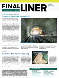
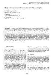
Chapter 35TUNNELING ON THE TREN URBANO PROJECT,SAN JUAN, PUERTO RICOMichael GayProject Sp<strong>on</strong>sor, Kiewit, Kenny, Zachary (KKZ)G. RippentropProject Manager, Kiewit, Kenny, Zachary (KKZ)W.H. HansmirePrincipal, <strong>Jacobs</strong> AssociatesV.S. RomeroProject Manager, <strong>Jacobs</strong> AssociatesABSTRACTThe new Tren Urbano heavy rail transit <strong>project</strong> in San Juan, Puerto Rico has<strong>on</strong>e very significant part, <strong>the</strong> Río Piedras C<strong>on</strong>tract, being c<strong>on</strong>structed underground.This paper will give an overview of <strong>the</strong> <str<strong>on</strong>g>tunneling</str<strong>on</strong>g> work that started c<strong>on</strong>structi<strong>on</strong> in1997. Design-Build procurement for <str<strong>on</strong>g>tunneling</str<strong>on</strong>g> is addressed.The new and modern transit system in San Juan will be 17.2 km (10.7 mi)l<strong>on</strong>g and have 16 stati<strong>on</strong>s in its first segment of c<strong>on</strong>structi<strong>on</strong>, which is due to openin 2001. The line c<strong>on</strong>nects <strong>the</strong> city center district of Santurce to <strong>the</strong> outlying suburbanmunicipality of Bayamón. All c<strong>on</strong>structi<strong>on</strong> is being d<strong>on</strong>e under design-buildc<strong>on</strong>tracts as a dem<strong>on</strong>strati<strong>on</strong> <strong>project</strong> funded by <strong>the</strong> Comm<strong>on</strong>wealth of PuertoRico and <strong>the</strong> Federal Transit Administrati<strong>on</strong> (FTA).The Río Piedras C<strong>on</strong>tract is completely underground and involves practicallyall types of c<strong>on</strong>structi<strong>on</strong> in soft ground. One stati<strong>on</strong> is built as cut-and-cover at <strong>the</strong>University of Puerto Rico. One porti<strong>on</strong> has twin tunnels to be driven with an EarthPressure Balance Machine (EPBM) and lined with <strong>on</strong>e-pass precast c<strong>on</strong>cretesegments. Ano<strong>the</strong>r has four short tunnel drives at a turnout that will be c<strong>on</strong>structedwith an initial support of shotcrete and lattice girders (i.e., <strong>the</strong> New AustrianTunneling Method of c<strong>on</strong>structi<strong>on</strong>). The most complex c<strong>on</strong>structi<strong>on</strong> is <strong>the</strong> RíoPiedras Stati<strong>on</strong>, which is being built as a stacked drift with a total of 15 individualtunnel drifts. After being sequentially excavated and c<strong>on</strong>creted, <strong>the</strong>y will form <strong>the</strong>arch of <strong>the</strong> 19 m (62 ft.) wide by 16 m (53 ft.) high cavern stati<strong>on</strong>. This structure isexcavated in soil with less than 5 m (16 ft.) of cover to overlying historic buildings.INTRODUCTIONBackground of <strong>the</strong> Tren Urbano ProjectThe island of Puerto Rico, a self governing comm<strong>on</strong>wealth of <strong>the</strong> UnitedStates, is located approximately 1,500 km (930 mi) from Miami, Florida (seeFigure 1). Though <strong>on</strong>ly 160 km (100 mi) l<strong>on</strong>g by 56 km (35 mi) wide, Puerto Ricohas a populati<strong>on</strong> of 3.8 milli<strong>on</strong>. About <strong>on</strong>e-third of <strong>the</strong> Island's residents, 1.3milli<strong>on</strong>, live in <strong>the</strong> San Juan Metropolitan Area (SJMA), a regi<strong>on</strong> <strong>on</strong> <strong>the</strong> nor<strong>the</strong>ast
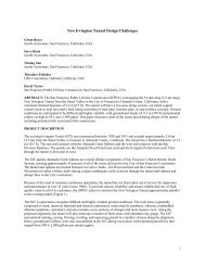
6221999 RETC PROCEEDINGSFigure 1. Map of Nor<strong>the</strong>rn Caribbeancoast encompassing 13 municipalities and 1,000 km 2 (390 mi 2 ). The populati<strong>on</strong>of <strong>the</strong> SJMA generates about 3.2 milli<strong>on</strong> vehicular trips per day. An estimated4,200 vehicles per square mile in <strong>the</strong> central SJMA create <strong>on</strong>e of <strong>the</strong> most c<strong>on</strong>gestedurban roadway networks in <strong>the</strong> world. By 2010, vehicle trips per day are expectedto rise by 45% over 1990 levels.In <strong>the</strong> spring of 1994 <strong>the</strong> present administrati<strong>on</strong> of <strong>the</strong> Government of PuertoRico approved plans for a heavy rail transit system. Tren Urbano (translated asUrban Train) was chosen as <strong>the</strong> name of <strong>the</strong> <strong>project</strong>, as well as <strong>the</strong> organizati<strong>on</strong>formed to build and maintain <strong>the</strong> <strong>project</strong>. The Tren Urbano Organizati<strong>on</strong> (TUO) isassociated with <strong>the</strong> Puerto Rico Highway and Transportati<strong>on</strong> Authority (PRHTA).The initial phase of <strong>the</strong> Tren Urbano Project will serve three central municipalitiesof <strong>the</strong> SJMA (Bayamón, Guaynabo, and San Juan), and will cost an estimated$1.25 billi<strong>on</strong>. The Federal Transit Authority (FTA) provides 30% of <strong>the</strong> <strong>project</strong>'sfunding, with <strong>the</strong> balance provided by <strong>the</strong> PRHTA.The Turnkey Dem<strong>on</strong>strati<strong>on</strong> Program, created by C<strong>on</strong>gress in <strong>the</strong> IntermodalSurface Transportati<strong>on</strong> Efficiency Act of 1991, is testing alternative turnkey, anddesign-build, c<strong>on</strong>structi<strong>on</strong> techniques with <strong>the</strong> goal of expediting <strong>project</strong> timelines, reducing <strong>project</strong> costs, and rati<strong>on</strong>ally allocating <strong>project</strong> risks. Tren Urbanois <strong>on</strong>e of four dem<strong>on</strong>strati<strong>on</strong> <strong>project</strong>s in <strong>the</strong> United States. The goal is to providea cost effective <strong>project</strong> while achieving <strong>project</strong> ec<strong>on</strong>omic, transportati<strong>on</strong>, energy,envir<strong>on</strong>mental and safety objectives.The Phase I alignment of <strong>the</strong> Tren Urbano Project c<strong>on</strong>nects <strong>the</strong> populouswestern municipality of Bayamón with Santurce, passing through <strong>the</strong> municipalityof Guaynabo and <strong>the</strong> districts of sou<strong>the</strong>rn and central San Juan known as RíoPiedras and Hato Rey (see Figure 2). The line is 17.2 km (10.7 miles) from end toend; it has 16 stati<strong>on</strong>s and a centrally located storage and maintenance yardwhere <strong>the</strong> operati<strong>on</strong>s center will also be located. About 40% of <strong>the</strong> line will be atgradeand 60% elevated over principal avenues. The <strong>on</strong>ly excepti<strong>on</strong> is <strong>the</strong> tunnel
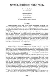
TUNNELING ON THE TREN URBANO PROJECT623Figure 2. Phase I Tren Urbano Alignmentsecti<strong>on</strong> through most of <strong>the</strong> heavily c<strong>on</strong>gested and historically rich district of RíoPiedras. This paper describes <strong>the</strong> tunneled guideway secti<strong>on</strong>s and stati<strong>on</strong> thatcomprise <strong>the</strong> Río Piedras C<strong>on</strong>tract.Río Piedras C<strong>on</strong>tractIn 1994, <strong>the</strong> PRHTA engaged a General Management, Architectural andEngineering C<strong>on</strong>sultant (GMAEC) to produce a 30% design that would be bid <strong>on</strong>as design-build c<strong>on</strong>tracts. The GMAEC team members include Daniel, Mann,Johns<strong>on</strong>, and Mendenhall; Frederic R. Harris, Inc.; Eduardo Molinari y Asociados;and Barret & Hale. The Río Piedras C<strong>on</strong>tract was advertised by <strong>the</strong> PRHTA in Juneof 1996. Three joint ventures of c<strong>on</strong>tracting and engineering design firms submittedproposals. Award and notice to proceed were given simultaneously <strong>on</strong> April 18,1997 to <strong>the</strong> KKZ/CMA joint venture, which comprises three c<strong>on</strong>tractors: KiewitC<strong>on</strong>structi<strong>on</strong>, Kenny C<strong>on</strong>structi<strong>on</strong>, and H.B. Zachry Company. The managingdesigner is <strong>the</strong> Puerto Rico firm, CMA Architects & Engineers. Subc<strong>on</strong>tractorengineering firms include <strong>Jacobs</strong> Associates (tunnel structural design), SverdrupCivil (stati<strong>on</strong> structural/architectural design and mechanical/electrical design),and Woodward-Clyde (geotechnical explorati<strong>on</strong> and instrumentati<strong>on</strong>). The bid byKKZ/CMA of $225,600,000 was determined to be <strong>the</strong> best value of <strong>the</strong> three bidders.The Río Piedras C<strong>on</strong>tract c<strong>on</strong>sists of a 1,500 m (4900 ft.) l<strong>on</strong>g undergroundrapid transit guideway with two underground subway stati<strong>on</strong>s (see Figure 3). The<strong>project</strong> is situated in a dense urban area, and geotechnical c<strong>on</strong>diti<strong>on</strong>s c<strong>on</strong>sist ofwea<strong>the</strong>red alluvium (soft ground). Most of <strong>the</strong> <strong>project</strong> structures are located below<strong>the</strong> groundwater table, and many of <strong>the</strong> tunnels pass beneath occupied historicalbuildings with less than 5 m (16 ft.) of cover.Secti<strong>on</strong>s of <strong>the</strong> guideway and <strong>the</strong> University Puerto Rico Stati<strong>on</strong> are beingc<strong>on</strong>structed by cut-and-cover methods. The o<strong>the</strong>r guideway secti<strong>on</strong>s and <strong>the</strong> Río
6241999 RETC PROCEEDINGSFigure 3. Plan of Río Piedras C<strong>on</strong>tract
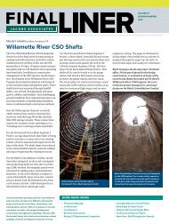
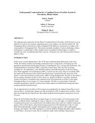
TUNNELING ON THE TREN URBANO PROJECT625Piedras Stati<strong>on</strong>, which are being c<strong>on</strong>structed by various <str<strong>on</strong>g>tunneling</str<strong>on</strong>g> methods, are<strong>the</strong> focus of this paper. The tunneled porti<strong>on</strong>s of <strong>the</strong> work have three differentc<strong>on</strong>structi<strong>on</strong> methods:· Mined Tunnels (NATM).· Río Piedras Stati<strong>on</strong> - Stacked Drift Tunnel.· Circular Earth Tunnels (EPBM).GEOTECHNICAL CONDITIONSSite stratigraphy principally includes thick sequences of marine depositsoverlain by alluvium. Locally, artificially placed fills are present, reflecting urbandevelopment al<strong>on</strong>g <strong>the</strong> <strong>project</strong> alignment. Soil and rock units (in descendingorder) that influence design and c<strong>on</strong>structi<strong>on</strong> include:· Artificial Fills.· Hato Rey Formati<strong>on</strong> (old alluvium).· Aquada Limest<strong>on</strong>e.A simplified geologic profile al<strong>on</strong>g <strong>the</strong> <strong>project</strong> alignment is shown <strong>on</strong>Figure 4.Underlying <strong>the</strong> man-placed fills in <strong>the</strong> <strong>project</strong> area, <strong>the</strong> Hato Rey Formati<strong>on</strong>(old alluvium) c<strong>on</strong>sists of silty clays, silts, and clayey to silty <strong>san</strong>ds with occasi<strong>on</strong>alinterbeds of comparatively clean <strong>san</strong>ds. The thickness of <strong>the</strong> Hato Rey Formati<strong>on</strong>identified in <strong>the</strong> <strong>project</strong> borings ranges from about 15 to 20 meters. The densityof <strong>the</strong> <strong>san</strong>ds is variable but usually dense to very dense (SPT blow counts of 50and higher), and <strong>the</strong> c<strong>on</strong>sistency of <strong>the</strong> fine grained soils ranges from mediumto stiff. The most characteristic feature of <strong>the</strong> old alluvium is <strong>the</strong> extensivec<strong>on</strong>versi<strong>on</strong> of n<strong>on</strong>-quartz c<strong>on</strong>stituents to clay, although <strong>the</strong> original <strong>san</strong>d andgravel texture of <strong>the</strong> deposits is usually visible despite <strong>the</strong> advanced state ofalterati<strong>on</strong> and wea<strong>the</strong>ring. In additi<strong>on</strong>, <strong>the</strong> old alluvium is prec<strong>on</strong>solidatedby desiccati<strong>on</strong>.Excluding <strong>the</strong> small cap of fill (generally less than 1 meter thick), <strong>the</strong> tunnelsare generally within <strong>the</strong> Hato Rey Formati<strong>on</strong>. For <strong>the</strong> design, <strong>the</strong> Hato ReyFormati<strong>on</strong> within <strong>the</strong> tunnel profiles has been divided into three soil layers forsimplicity. These layers are referred to (from top to bottom):· Layer 1 - Upper Clays: Characterized as overc<strong>on</strong>solidated, stiff silty clays.This layer was assumed to be a cohesive soil (f=0).· Layer 2 - Middle Stratified Z<strong>on</strong>e: Characterized as alternating layers ofclean <strong>san</strong>d, silty <strong>san</strong>d, clayey <strong>san</strong>d, and clay. These soils c<strong>on</strong>tain relictstructure of <strong>the</strong> original <strong>san</strong>d and gravel texture of <strong>the</strong> alluvium. The claylayers are stiff to very stiff, and silty/<strong>san</strong>dy layers are typically medium
626LIMESTONEUPPER CLAYMIDDLE STRATIFIED ZONELOWER SANDGRAPHIC SCALE0 20 40 6080 100(HORIZONTAL:VERTICAL = 5:1)GROUND SURFACE1999 RETC PROCEEDINGSFigure 4. Geologic Profile of Río Piedras C<strong>on</strong>tract Alignment
TUNNELING ON THE TREN URBANO PROJECT627dense with density increasing with depth. Silty and clayey layers c<strong>on</strong>tainappreciable fines (30 to 50 percent). The transiti<strong>on</strong> between Layer 1 (siltyclays) and Layer 2 (silty/clayey <strong>san</strong>ds) is <strong>the</strong> result of wea<strong>the</strong>ring and is<strong>the</strong>refore gradati<strong>on</strong>al in nature. Layer 1 is distinguished from Layer 2 by<strong>the</strong> greater fines c<strong>on</strong>tent in <strong>the</strong> Layer 1. This is due to wea<strong>the</strong>ring, in that agreater percentage of <strong>the</strong> <strong>san</strong>ds have wea<strong>the</strong>red to clay near <strong>the</strong> groundsurface. Both layers are highly lenticular. However, to simplify <strong>the</strong> analyses,this wea<strong>the</strong>ring profile has been broken into <strong>the</strong>se two layers. Layers 1and 2 have fairly low hydraulic c<strong>on</strong>ductivities in <strong>the</strong> vertical and horiz<strong>on</strong>taldirecti<strong>on</strong>s. Layer 2 was also assumed to be a cohesive soil (f=0).· Layer 3 - Lower Sand: Characterized as interbedded <strong>san</strong>ds, silty andclayey <strong>san</strong>ds, and clays. Layer 3 c<strong>on</strong>tains clean lenses of coarse-graineddeposits up to 2 meters in thickness. Cemented horiz<strong>on</strong>s within Layer 3occur in horiz<strong>on</strong>tal layers 1 to 2 meters in thickness. Layer 3 is a distinctlydifferent layer that has different material properties from Layers 1 and 2. Itis a more coarse grained layer (more <strong>san</strong>d) and has higher hydraulicc<strong>on</strong>ductivities that are more c<strong>on</strong>ducive to dewatering than Layers 1 and2.This layer was assumed be a soil with both c and f.Below <strong>the</strong> Lower Sand lies <strong>the</strong> Aquada Limest<strong>on</strong>e. In porti<strong>on</strong>s of <strong>the</strong> alignment,<strong>the</strong> Aquada Limest<strong>on</strong>e forms pinnacles or buried karst features that intrude into<strong>the</strong> Río Piedras Stati<strong>on</strong> invert. At <strong>the</strong>se locati<strong>on</strong>s <strong>the</strong> limest<strong>on</strong>e is slightly tomoderately wea<strong>the</strong>red, and does not make much water.A typical geotechnical profile for <strong>the</strong> Mined Tunnels is shown <strong>on</strong> Figure 5. Thenumbers <strong>on</strong> Figure 5 (1, 2, 3 and 4) indicate <strong>the</strong> sequence of excavati<strong>on</strong>.Seismicity. Puerto Rico has a record of earthquake activity since Spanishcol<strong>on</strong>izati<strong>on</strong> and is situated between three major fault z<strong>on</strong>es. No active faultshave been identified <strong>on</strong> <strong>the</strong> island, but epicenters of deep and moderate dep<strong>the</strong>arthquakes have been identified beneath <strong>the</strong> island. Hundreds of smallmagnitude shocks occur in <strong>the</strong> vicinity of Puerto Rico each year, but most gounnoticed except by highly sensitive seismographs. Historically, large magnitudeevents have been felt in Puerto Rico. The entire island is rated as Seismic Z<strong>on</strong>e3 by <strong>the</strong> 1997 Uniform Building Code.In <strong>the</strong> case of <strong>the</strong> Río Piedras underground structures, <strong>the</strong> design teamc<strong>on</strong>cluded that <strong>the</strong> Río Piedras alignment does not cross any active faults thatcould impart displacement due to fault rupture.DESIGN OF UNDERGROUND STRUCTURESDesign Approach <strong>on</strong> a Design-Build ProjectThe design approach <strong>on</strong> a design-build <strong>project</strong> is somewhat different than istypically experienced <strong>on</strong> design-bid-build <strong>project</strong>s. On <strong>the</strong> Tren Urbano <strong>project</strong>,<strong>the</strong>re were three primary factors that drove <strong>the</strong> design approach:1. Compressed Schedule. The short c<strong>on</strong>tract durati<strong>on</strong>, <strong>on</strong>ly 43 m<strong>on</strong>ths, meantthat c<strong>on</strong>structi<strong>on</strong> had to start at <strong>the</strong> same time as <strong>the</strong> design. This led <strong>the</strong>designers to issue “definitive designs” with c<strong>on</strong>crete outlines so thatinstallati<strong>on</strong> of temporary excavati<strong>on</strong> support could proceed.
6281999 RETC PROCEEDINGSFigure 5. Typical Geotechnical Profile for Mined Tunnels2. Owner-Provided Preliminary Design. The 30% design provided by <strong>the</strong>owner was essential to define overall facility requirements. However, itwas necessary to customize <strong>the</strong> preliminary design to <strong>the</strong> specificunderground c<strong>on</strong>structi<strong>on</strong> methods being used by <strong>the</strong> c<strong>on</strong>tractor. Thissometimes lead to significant redesign efforts.3. Focus <strong>on</strong> Procurement to Meet Schedule. In order to meet materialprocurement requirements, particularly <strong>on</strong> an island where many materialshad to be shipped overseas, designers had to advance designs so that<strong>the</strong> procurement schedule was not impacted. This required a c<strong>on</strong>certedeffort to keep design ahead of procurement and c<strong>on</strong>structi<strong>on</strong>. It also meantthat <strong>the</strong> designers had to anticipate requirements for <strong>the</strong> final structure,even though <strong>the</strong> final design had not yet been completed.In additi<strong>on</strong> to <strong>the</strong>se factors, <strong>the</strong> designer/c<strong>on</strong>tractor relati<strong>on</strong>ship is differentthan <strong>the</strong> typical design/owner relati<strong>on</strong>ship. The designer best serves <strong>the</strong> c<strong>on</strong>tractorclientby meeting schedule. However, <strong>the</strong> designer is still “engineer of record” for<strong>the</strong> work, with all <strong>the</strong> resp<strong>on</strong>sibilities that are inherent in <strong>the</strong> professi<strong>on</strong>, such aspublic safety, adherence to governing laws and codes, ethical c<strong>on</strong>duct, etc.Building Protecti<strong>on</strong> and DewateringFor <strong>the</strong> Río Piedras c<strong>on</strong>tract documents, <strong>the</strong> owner specified threshold limit<strong>san</strong>d specific acti<strong>on</strong>s for various levels of settlement. Compensati<strong>on</strong> grouting hasbeen selected as an appropriate building protecti<strong>on</strong> method since it is c<strong>on</strong>sidered
TUNNELING ON THE TREN URBANO PROJECT629<strong>the</strong> most appropriate procedure to mitigate settlements caused by excavati<strong>on</strong> of<strong>the</strong> various tunnels. Compensati<strong>on</strong> grouting design and c<strong>on</strong>structi<strong>on</strong> is beingprovided by Soletanche-Bachy of Paris, France.The phases of <strong>the</strong> compensati<strong>on</strong> grouting program above <strong>the</strong> tunnels areas follows:1. Identify <strong>the</strong> areas to be protected.2. Drilling and installati<strong>on</strong> of sleeve port pipes (also termed tube-a-manchete)in an array beneath areas that are expected to be influenced by excavati<strong>on</strong>settlements. (The sleeve port pipes make it possible to inject compensati<strong>on</strong>grout precisely beneath a particular z<strong>on</strong>e utilizing an inflatabledouble packer.)3. Pre-grouting or pre-c<strong>on</strong>diti<strong>on</strong>ing is performed to recover relaxati<strong>on</strong> due todrilling, and to pre-compact <strong>the</strong> ground so that subsequent injecti<strong>on</strong>s aremore immediately effective in compensating for settlement.4. The compensati<strong>on</strong> grouting phase is undertaken as required during <strong>the</strong>excavati<strong>on</strong> work to compensate for ground loss and limit settlement to anacceptable value. The pressure, volume, and locati<strong>on</strong> for injecti<strong>on</strong> of groutis based <strong>on</strong> informati<strong>on</strong> obtained through instrumentati<strong>on</strong> of building<strong>san</strong>d surface movement.The c<strong>on</strong>cept of compensati<strong>on</strong> grouting is shown in Figure 6. Details of <strong>the</strong>compensati<strong>on</strong> grouting program are given in “Ground C<strong>on</strong>trol Program for <strong>the</strong>Río Piedras Project, Tren Urbano Program, San Juan, Puerto Rico” by Morris<strong>on</strong> etal., which is also in <strong>the</strong>se proceedings.Dewatering for <strong>the</strong> tunnels is being performed from deep pumped wells andby pumping in <strong>the</strong> open cuts. In additi<strong>on</strong>, probe holes are being drilled ahead oftunnel excavati<strong>on</strong>s if warranted by geologic c<strong>on</strong>diti<strong>on</strong>s. Horiz<strong>on</strong>tal drains and/orvacuum lances have been used to pre-drain tunnel headings to c<strong>on</strong>trol unfavorableground c<strong>on</strong>diti<strong>on</strong>s. In general, <strong>the</strong> soils encountered during tunnel excavati<strong>on</strong> aresilty to <strong>san</strong>dy clays and clayey to silty <strong>san</strong>ds with low hydraulic c<strong>on</strong>ductivities.Tunnel Design and Analysis ApproachDesign of <strong>the</strong> NATM and EPBM tunnels generally followed industry practicefor design of flexible linings in soft ground. However, due to <strong>the</strong> shallow depth and<strong>the</strong> relatively stiff nature of <strong>the</strong> stacked drift tunnel, numerical models were usedto determine stresses and deformati<strong>on</strong> of structures. In additi<strong>on</strong>, due to <strong>the</strong> closeproximity of <strong>the</strong> NATM tunnels to <strong>on</strong>e ano<strong>the</strong>r, numerical models were also usedto analyze <strong>the</strong> interacti<strong>on</strong> between parallel tunnels.Three structural models were used to analyze <strong>the</strong> behavior of <strong>the</strong> NATM tunnel<strong>san</strong>d <strong>the</strong> Stacked Drift Tunnel:· Finite Difference C<strong>on</strong>tinuum Model: Used for <strong>the</strong> NATM tunnels and StackedDrift Tunnel to analyze <strong>the</strong> behavior of <strong>the</strong> tunnel linings. This analyticalapproach involved modeling <strong>the</strong> excavati<strong>on</strong> sequence and <strong>the</strong> installati<strong>on</strong>
6301999 RETC PROCEEDINGSFigure 6. Compensati<strong>on</strong> Grouting Schematicof initial linings at <strong>the</strong> appropriate stage of c<strong>on</strong>structi<strong>on</strong>. The FLAC software,produced by Itasca Corp., was used for <strong>the</strong>se models. The 2-dimensi<strong>on</strong>alnumerical models simulate <strong>the</strong> soil as an elasto-plastic c<strong>on</strong>tinua andmodels <strong>the</strong> initial linings ei<strong>the</strong>r as structural beam elements or as elasticc<strong>on</strong>tinua.· Beam-Spring Model: Structural frame analyses where used for <strong>the</strong> finallinings of <strong>the</strong> NATM tunnels and <strong>the</strong> Stacked Drift Tunnel. With this method<strong>the</strong> linings are modeled as a network of beams. The interacti<strong>on</strong> of <strong>the</strong>lining with <strong>the</strong> surrounding ground is modeled by a series of springs.Elastic material properties were used and structural loads were directlyentered into this model.· Three-Hinged Arch Model: This simplified representati<strong>on</strong> of an archstructure as a statically determinant structure, with a hinge assumed at<strong>the</strong> centerline of <strong>the</strong> arch at <strong>the</strong> crown, was used for analysis of <strong>the</strong> StackedDrift Tunnel. The three-hinge arch model was used to compute <strong>the</strong> reacti<strong>on</strong>sat <strong>the</strong> foundati<strong>on</strong> and invert slab levels.The design of each individual tunnel structure is summarized below.Mined Tunnels (NATM)The Mined Tunnels will be c<strong>on</strong>structed to preserve two historic structureslocated near <strong>the</strong> sou<strong>the</strong>ast corner of <strong>the</strong> intersecti<strong>on</strong> of Georgetti Street and P<strong>on</strong>ce
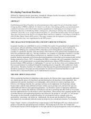
TUNNELING ON THE TREN URBANO PROJECT631de León Avenue. Because of <strong>the</strong> short length of tunnels, mechanized shield<str<strong>on</strong>g>tunneling</str<strong>on</strong>g> was not c<strong>on</strong>sidered an ec<strong>on</strong>omically viable opti<strong>on</strong> for tunnel excavati<strong>on</strong>.In additi<strong>on</strong>, to limit settlement and prevent damage to <strong>the</strong> existing buildings above<strong>the</strong> tunnel, c<strong>on</strong>siderati<strong>on</strong> was given to various tunnel excavati<strong>on</strong> and supportmethods. It was c<strong>on</strong>cluded that c<strong>on</strong>structi<strong>on</strong> aspects of <strong>the</strong> NATM offer <strong>the</strong> mostflexibility in c<strong>on</strong>structi<strong>on</strong>, and is an effective method for c<strong>on</strong>trolling surface groundsettlement (Rippentrop and Kolitsch 1997).A total of four mined guideway tunnels, each approximately 100 m (330 ft.)l<strong>on</strong>g, will be c<strong>on</strong>structed under two historic structures. Two of <strong>the</strong> four tunnels willbe c<strong>on</strong>structed as part of a turnout to a future line. Cover over <strong>the</strong> Mined Tunnelsranges from 20 m (66 ft.) to 5 m (16 ft.). Some of <strong>the</strong> tunnels are located less than1 meter from each o<strong>the</strong>r in <strong>the</strong> turnout secti<strong>on</strong>. Critical secti<strong>on</strong>s of <strong>the</strong> MinedTunnels are shown <strong>on</strong> Figures 7 and 8.A two-pass system c<strong>on</strong>sisting of a lattice girder and mesh reinforced shotcreteinitial lining and a cast-in-place c<strong>on</strong>crete final lining was c<strong>on</strong>sidered appropriatefor <strong>the</strong>se tunnels. The initial lining as c<strong>on</strong>structed is shown in Figure 9. The finallining for <strong>the</strong> NATM tunnels serves to support l<strong>on</strong>g-term hydrostatic and seismicloads, and provide a foundati<strong>on</strong> and dynamic envelope for trains and walkways. Awaterproof membrane will be installed between <strong>the</strong> initial lining and <strong>the</strong>final lining.Due to <strong>the</strong> complex geometries and excavati<strong>on</strong> sequences of <strong>the</strong> varioustunnels in relati<strong>on</strong> to each o<strong>the</strong>r, <strong>the</strong> finite difference method was used for analysisof <strong>the</strong> initial support. The analysis took into c<strong>on</strong>siderati<strong>on</strong> <strong>the</strong> deformati<strong>on</strong> of <strong>the</strong>ground prior to placement of <strong>the</strong> final lining. Fur<strong>the</strong>rmore, stress redistributi<strong>on</strong>swere fully taken into account as <strong>on</strong>e tunnel is excavated and supported next to anadjacent, previously c<strong>on</strong>structed tunnel.Río Piedras Stati<strong>on</strong> Stacked Drift TunnelThe tunnel for <strong>the</strong> Río Piedras Stati<strong>on</strong> platform, 150 meters (490 ft.) l<strong>on</strong>g by19 m (62 ft.) wide by 16 m (53 ft.) in height, will be <strong>on</strong>e of <strong>the</strong> largest diameter soiltunnels ever c<strong>on</strong>structed (see Figure 10). This structure will be built using astacked drift design, in which <strong>the</strong> tunnel lining, c<strong>on</strong>sisting of 15 c<strong>on</strong>crete filleddrifts, is c<strong>on</strong>structed to form a horseshoe-shaped arch. C<strong>on</strong>structi<strong>on</strong> of <strong>the</strong> archis followed by removal of <strong>the</strong> soil core under <strong>the</strong> arch. Many factors, which includevariable soil c<strong>on</strong>diti<strong>on</strong>s, overlying historic structures, relatively shallow tunneldepth (less than 5 m), and small permissible ground settlements, have influencedthis design and c<strong>on</strong>structi<strong>on</strong> approach.The approach has precedents in <strong>the</strong> United States in very poor groundc<strong>on</strong>diti<strong>on</strong>s for a part of <strong>the</strong> Eisenhower Tunnel <strong>on</strong> Interstate 70 in Colorado (Hopperet al. 1972) and for <strong>the</strong> Mount Baker Ridge Tunnel <strong>on</strong> Interstate 90 in Seattle,Washingt<strong>on</strong> (Robins<strong>on</strong> et al. 1983; Johns<strong>on</strong> et al. 1983).The Stacked Drift Tunnel could be c<strong>on</strong>sidered to behave like an unreinforcedarch where loads are accommodated as compressive forces (thrust) acrossindividual arch segments. As an arch it could be stable without steel reinforcement.This was <strong>the</strong> case for <strong>the</strong> Mount Baker Ridge Tunnel. The difference between<strong>the</strong>se two <strong>project</strong>s, however, are significant: Mount Baker Ridge has a full circularring, is situated in clayey soils without appreciable groundwater, and has less
6321999 RETC PROCEEDINGSFigure 7. Mined Tunnels Cross-Secti<strong>on</strong> at Stati<strong>on</strong> 219+10Figure 8. Mined Tunnels Cross-Secti<strong>on</strong> at Stati<strong>on</strong> 218+70
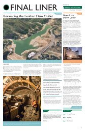
TUNNELING ON THE TREN URBANO PROJECT633Figure 9. Lattice Girder and Mesh Reinforced Shotcrete LiningFigure 10. Stacked Drift Tunnel
6341999 RETC PROCEEDINGSc<strong>on</strong>cern for overlying structures. The Río Piedras Stati<strong>on</strong> arch is not circular buthorseshoe in shape, has significant groundwater c<strong>on</strong>cerns, and has occupiedcommercial and residential structures directly overhead. Thus, regardless ofhow much <strong>the</strong> Stacked Drift Tunnel might actually functi<strong>on</strong> as an arch, a reinforcedc<strong>on</strong>crete arch was deemed to be appropriate for this situati<strong>on</strong>.Since <strong>the</strong> arch will be structurally effective before <strong>the</strong> soil core is removed, itwas designed to accommodate loads associated with both short term and l<strong>on</strong>gterm c<strong>on</strong>diti<strong>on</strong>s. In c<strong>on</strong>venti<strong>on</strong>al <str<strong>on</strong>g>tunneling</str<strong>on</strong>g>, most of <strong>the</strong> elastic and some of <strong>the</strong>inelastic deformati<strong>on</strong>s of <strong>the</strong> ground occur before tunnel supports are installedand become structurally effective. This results in arching of soil, thus reducingload <strong>on</strong> <strong>the</strong> tunnel supports. Because of <strong>the</strong> c<strong>on</strong>structi<strong>on</strong> method planned for <strong>the</strong>Rio Piedras Stati<strong>on</strong>, substantial soil arching cannot develop.Tunnel Geometry. Drifts were sized to achieve a c<strong>on</strong>structable opening yet besmall enough to minimize c<strong>on</strong>structi<strong>on</strong> impact <strong>on</strong> overlying structures. Structuralrequirements for <strong>the</strong> arch did not c<strong>on</strong>trol size. For c<strong>on</strong>structability reas<strong>on</strong>s <strong>the</strong>drifts are oversized with respect to minimum structural requirements. For <strong>the</strong>lower drifts forming <strong>the</strong> sidewall, a nominal size of 3 m (9.8 ft.) by 3 m wasselected. Drifts were designed to be rectangular in shape. In <strong>the</strong> upper drifts,blockouts are necessary where <strong>the</strong> drift encroaches <strong>on</strong> <strong>the</strong> clearance requiredinside <strong>the</strong> tunnel (see Figure 10).Steel Reinforcement. For <strong>the</strong> most part, structural steel is being used tocreate a reinforced c<strong>on</strong>crete structure. Where possible, parts of <strong>the</strong> steel setsrequired for individual drift c<strong>on</strong>structi<strong>on</strong> are used for reinforcement of <strong>the</strong> overallstacked drift structure. Sidewall reinforcement is provided by <strong>the</strong> sidewall driftposts, while porti<strong>on</strong>s of <strong>the</strong> crown reinforcement of <strong>the</strong> arch are provided by driftcap beams. Short-term and l<strong>on</strong>g-term loading c<strong>on</strong>diti<strong>on</strong>s require reinforcement<strong>on</strong> different faces of <strong>the</strong> structure, as shown in Figure 11.Special attenti<strong>on</strong> is given to reinforce <strong>the</strong> arch for cases when a positivemoment (tensi<strong>on</strong> <strong>on</strong> <strong>the</strong> inside face of <strong>the</strong> arch) develops. In this situati<strong>on</strong>, <strong>the</strong>initial steel installed in <strong>the</strong> drifts cannot be utilized for reinforcement due to <strong>the</strong>irlocati<strong>on</strong>. A separate installati<strong>on</strong> is made of structural steel to provide tensi<strong>on</strong>reinforcement <strong>on</strong> <strong>the</strong> inside face of <strong>the</strong> crown of <strong>the</strong> arch. This arch steel isnecessarily spaced between <strong>the</strong> initial support steel. A special reinforcing barc<strong>on</strong>necti<strong>on</strong> is made in drifts 3, 4 and 5 to avoid problems of c<strong>on</strong>necting structuralsecti<strong>on</strong>s that have been pieced toge<strong>the</strong>r from drift to drift.Arch steel will be placed <strong>on</strong> regular spacing of 1.2 m (4 ft.) between <strong>the</strong> driftsteel. It will be installed in secti<strong>on</strong>s as <strong>the</strong> upper drifts are excavated. Blockoutsmust be placed in <strong>the</strong> sides and inverts of <strong>the</strong> upper drifts prior to c<strong>on</strong>creting of <strong>the</strong>drifts to form a curved surface <strong>on</strong> <strong>the</strong> inside face of <strong>the</strong> arch (see Figure 11).Certain c<strong>on</strong>necti<strong>on</strong>s between <strong>the</strong> various structural steel members acting asarch reinforcement must develop full s<strong>tren</strong>gth of <strong>the</strong> member in tensi<strong>on</strong>. O<strong>the</strong>rc<strong>on</strong>necti<strong>on</strong>s need <strong>on</strong>ly be partial-s<strong>tren</strong>gth c<strong>on</strong>necti<strong>on</strong>s. The locati<strong>on</strong>s of <strong>the</strong> fulls<strong>tren</strong>gthand partial-s<strong>tren</strong>gth c<strong>on</strong>necti<strong>on</strong>s are noted in Figure 11.Circular Earth Tunnels (EPBM)Twin bore guideway tunnels will be c<strong>on</strong>structed between <strong>the</strong> University ofPuerto Rico Stati<strong>on</strong> and <strong>the</strong> Río Piedras Stati<strong>on</strong>, a distance of approximately 430
TUNNELING ON THE TREN URBANO PROJECT635Figure 11. Structural Requirements for Stacked Drift Tunnel Reinforcementm (1,400 ft.). The twin 6.3 m (20.7 ft.) outside diameter Circular Earth Tunnels willbe excavated using a Lovat Model 254 earth pressure balance tunnel boringmachine (EPBM) that was used <strong>on</strong> <strong>the</strong> Washingt<strong>on</strong>, D.C. subway system,C<strong>on</strong>tracts F6a and F6c.The EPBM will be used with a “<strong>on</strong>e-pass” precast c<strong>on</strong>crete segmental liningsystem where individual segments with gasketed joints are bolted to form awatertight lining (see Figure 12). The tunnels pass under an historic fence ownedby <strong>the</strong> University of Puerto Rico, as well as under several occupied buildings. Asingle cross passage structure will be built between <strong>the</strong> two tunnels.The <strong>on</strong>e-pass lining is assembled in <strong>the</strong> tail-shield of <strong>the</strong> EPBM and boltedtoge<strong>the</strong>r. Grouting of <strong>the</strong> gap behind <strong>the</strong> segmental lining that is left byoverexcavati<strong>on</strong> of <strong>the</strong> tunnel will be d<strong>on</strong>e immediately behind <strong>the</strong> shield. Thelining is a seven piece, 250 mm (10 in.) thick, 1.2 meter (4 ft.) wide ring. Primarycircumferential reinforcing is eight #6 reinforcement bars <strong>on</strong> each face. Eachsegment will be joined using two 25 mm (1 in.) bolts in <strong>the</strong> circumferential directi<strong>on</strong>(14 total for 7 segments), and twelve 25 mm bolts in <strong>the</strong> l<strong>on</strong>gitudinal directi<strong>on</strong>.The <strong>on</strong>e-pass segmental lining is relatively flexible in relati<strong>on</strong> to <strong>the</strong> ground.As a result, <strong>the</strong> precast segmental lining will interact with <strong>the</strong> surrounding soil.This c<strong>on</strong>cept is fundamental to tunnel designs of this type. As a result, <strong>the</strong> designfor static loading c<strong>on</strong>diti<strong>on</strong>s was based <strong>on</strong> traditi<strong>on</strong>al flexible liner design c<strong>on</strong>cepts(Hansmire 1989; Keusel, et al. 1996; Peck 1969; Peck et al. 1972; andRanken 1978).
6361999 RETC PROCEEDINGSFigure 12. Precast Segment Bolting ArrangementVarious loading c<strong>on</strong>diti<strong>on</strong>s were c<strong>on</strong>sidered, including static soil loads,hydrostatic pressures, building surcharges, c<strong>on</strong>structi<strong>on</strong> loads, grouting loads,jacking loads, and seismic c<strong>on</strong>diti<strong>on</strong>s. Additi<strong>on</strong>al c<strong>on</strong>siderati<strong>on</strong>s includedreinforcement of <strong>the</strong> cast-in-place invert slab, gaskets between segments, andpotential for corrosi<strong>on</strong> and sulfate attack. Effects of excavating two tunnels adjacentto <strong>on</strong>e ano<strong>the</strong>r were also c<strong>on</strong>sidered. Structural adequacy of <strong>the</strong> c<strong>on</strong>crete segmentswas characterized by moment-thrust interacti<strong>on</strong> diagrams for reinforced c<strong>on</strong>crete.The following details were developed to adapt <strong>the</strong> “two-pass” segment designthat was recently completed <strong>on</strong> <strong>the</strong> WMATA F6a c<strong>on</strong>tract in Washingt<strong>on</strong>, D.C. (SeeFigure 13):· Bolt pocket detail was revised to minimize breakage of <strong>the</strong> segment thatoccurred in some instances as <strong>the</strong> bolts were tightened. Additi<strong>on</strong>alreinforcement was used around <strong>the</strong> pockets.· The segment thickness was revised from <strong>the</strong> thinner (230 mm, 9 in.)secti<strong>on</strong> used in Washingt<strong>on</strong>, D.C. to a 250 mm (10 in.) thick segment toprovide greater c<strong>on</strong>crete cover over reinforcement. In additi<strong>on</strong>, a sevenpiece ring was used in Puerto Rico instead of a five piece ring. Theserevisi<strong>on</strong>s are expected to alleviate cracks experienced in some segmentsthat were located in <strong>the</strong> crown of <strong>the</strong> tunnel.· The gasket groove was revised to maximize <strong>the</strong> distance between <strong>the</strong>groove and <strong>the</strong> edge of <strong>the</strong> segment. This is intended to minimize chippingof <strong>the</strong> gasket groove edge during handling.· Threaded plastic inserts, similar to what are being used <strong>on</strong> <strong>the</strong> Tor<strong>on</strong>toTransit Sheppard tunnels, were used in lieu of steel coil inserts.
TUNNELING ON THE TREN URBANO PROJECT637Figure 13. Typical Detail of Segment C<strong>on</strong>necti<strong>on</strong>Seismic Design of TunnelsEarthquakes have several effects <strong>on</strong> soft-ground tunnels:· Ground strains induced by seismic wave propagati<strong>on</strong>; and· Localized displacements induced by fault rupture.It has been c<strong>on</strong>cluded that <strong>the</strong> Río Piedras alignment does not cross anyactive faults that could impart displacement due to fault rupture. Therefore it was<strong>on</strong>ly necessary to examine <strong>the</strong> additi<strong>on</strong>al seismic loads imposed <strong>on</strong> <strong>the</strong> tunnelstructures, which are a manifestati<strong>on</strong> of <strong>the</strong> ground strains induced by seismicwave propagati<strong>on</strong>.If <strong>the</strong> wavelength is l<strong>on</strong>g compared to <strong>the</strong> size of <strong>the</strong> opening (as is anticipatedfor <strong>the</strong> Río Piedras C<strong>on</strong>tract), <strong>the</strong> dynamic loads can be approximated by usingpseudo-static methods. For <strong>the</strong> case of a disc<strong>on</strong>tinuous medium, groundaccelerati<strong>on</strong> can be used to calculate <strong>the</strong> seismic loads, and in <strong>the</strong> case of ac<strong>on</strong>tinuum, <strong>the</strong> dynamic stress can be calculated from wave propagati<strong>on</strong> <strong>the</strong>ory,provided <strong>the</strong> structure is sufficiently flexible.Earthquakes cause transient deformati<strong>on</strong> of <strong>the</strong> ground as <strong>the</strong>se varioustypes of waves travel through <strong>the</strong> ground. Many underground structures are flexiblein relati<strong>on</strong> to <strong>the</strong> ground; if this is <strong>the</strong> case, structures will be subject to <strong>the</strong> samestrains as <strong>the</strong> ground in which <strong>the</strong>y are embedded. Tren Urbano supplied designcriteria that gave formulas for axial, curvature, and hoop deformati<strong>on</strong> for tunnelstructures with cross-secti<strong>on</strong>s that are nearly circular. These formulae arevariati<strong>on</strong>s <strong>on</strong> <strong>the</strong> plain-strain equati<strong>on</strong>s used for determining seismic strains forflexible tunnel linings due to seismic wave propagati<strong>on</strong> (Wang 1993). Since <strong>the</strong>Mined Tunnels and Circular Earth Tunnel linings met <strong>the</strong> criteria for “flexible”tunnels in relati<strong>on</strong> to <strong>the</strong> ground, <strong>the</strong> owner furnished criteria was used for <strong>the</strong>
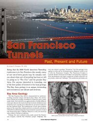
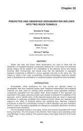
6381999 RETC PROCEEDINGSseismic analysis of <strong>the</strong>se structures. For <strong>the</strong> Stacked Drift Tunnel, which is arelatively stiff structure, a “racking” analysis was performed using a beam-springnumerical model.CONSTRUCTION PROGRESSMobilizati<strong>on</strong> to an IslandStockpiles of c<strong>on</strong>structi<strong>on</strong> materials are generally kept very small <strong>on</strong> <strong>the</strong>island of Puerto Rico. With <strong>the</strong> excepti<strong>on</strong> of cement, almost all materials of anysubstantial quantity must be ordered from off island and delivered.Material is transported to Puerto Rico via barge or vessel to <strong>the</strong> main docks inSan Juan. Several restricti<strong>on</strong>s <strong>on</strong> shipping drastically affected procurement ofmaterials: (1) All barges and vessels must be American flagships per Cooper Actrequirements; (2) The average length of materials (such as steel secti<strong>on</strong>s) isusually limited to 15 m (50 ft.) due to vessel or c<strong>on</strong>tainer size; (3) A minimumt<strong>on</strong>nage is required by <strong>the</strong> shipping companies; (4) Available space <strong>on</strong> oceangoing vessels is limited and material placed <strong>on</strong> <strong>the</strong> top deck must endure exposureto <strong>the</strong> elements.Integrati<strong>on</strong> of Procurement Schedule with DesignAt <strong>the</strong> start of this design-build <strong>project</strong> <strong>the</strong> drawings and specificati<strong>on</strong>s wereat a 30% design level. It was <strong>the</strong>n necessary for <strong>the</strong> c<strong>on</strong>tractor to identify criticalprocurement items so that <strong>the</strong> designer could advance <strong>the</strong> designs for thosespecific materials. Items that have a l<strong>on</strong>g lead time are of particular importance,such as forms for precast tunnel segments and fabricated steel sets and latticegirders for tunnel support. The c<strong>on</strong>tractor must also resist <strong>the</strong> urge to label allprocurement items as “critical,” o<strong>the</strong>rwise <strong>the</strong> designer will be unable to meetprocurement milest<strong>on</strong>es.Progress as of January 1999Building Protecti<strong>on</strong> and Dewatering. Sleeve port pipes have been installedin various locati<strong>on</strong>s below buildings within <strong>the</strong> z<strong>on</strong>e of influence above <strong>the</strong> tunnels.Installati<strong>on</strong>s have been made from <strong>the</strong> surface, within grout shafts, and within <strong>the</strong>grout gallery (drift G) above <strong>the</strong> Stacked Drift Tunnel. Dewatering has beenunderway for over a year, and has drawn down <strong>the</strong> water table below tunnel invertlevel in most locati<strong>on</strong>s.Temporary Support of Cut-and-Cover Excavati<strong>on</strong>s. Major cut-and-coverexcavati<strong>on</strong>s for <strong>the</strong> stati<strong>on</strong>s were substantially completed in 1998. Typicalc<strong>on</strong>structi<strong>on</strong> is soldier pile and lagging walls with internal bracing of structuralsteel or pipe. In limited areas secant pile walls were c<strong>on</strong>structed next to buildingstructures. Shafts were expedited to permit start of <str<strong>on</strong>g>tunneling</str<strong>on</strong>g> and o<strong>the</strong>r excavati<strong>on</strong>sproceeded in parallel for <strong>the</strong> University of Puerto Rico Stati<strong>on</strong> and <strong>the</strong> cut-andcoverguideway secti<strong>on</strong> at <strong>the</strong> north end of <strong>the</strong> <strong>project</strong>.NATM Tunnels. Mining of <strong>the</strong> first of <strong>the</strong> four tunnels was completed at <strong>the</strong> endof 1998 (see Figures 14 and 15) and <strong>the</strong> sec<strong>on</strong>d tunnel had turned under. In anover/under c<strong>on</strong>figurati<strong>on</strong> for a future rail line turnout, <strong>the</strong> final lining is specifically
TUNNELING ON THE TREN URBANO PROJECT639being delayed in order to avoid unnecessary stress in <strong>the</strong> final lining by c<strong>on</strong>structi<strong>on</strong>of <strong>the</strong> sec<strong>on</strong>d, overlying tunnel. After mining all tunnels, a final cast-in-placec<strong>on</strong>crete lining will be placed.Stacked Drift Tunnel. Shafts <strong>on</strong> ei<strong>the</strong>r end of <strong>the</strong> Stacked Drift Tunnel hadbeen sunk to invert level (see Figure 16). Mining of <strong>the</strong> level 2 drifts was in progress.Mining and c<strong>on</strong>creting of <strong>the</strong> lowest drifts (level 1), which form <strong>the</strong> tunnel foundati<strong>on</strong>,were completed in October of 1998 (see Figure 17). Mining <strong>the</strong> foundati<strong>on</strong> driftsinvolved substantial time as new work crews were trained for <strong>the</strong> somewhatunique mining techniques required. In additi<strong>on</strong>, limest<strong>on</strong>e was encountered in<strong>the</strong> lower half of <strong>the</strong> foundati<strong>on</strong> drifts for substantial reaches. For about <strong>the</strong> sou<strong>the</strong>rn<strong>on</strong>e-third of <strong>the</strong>se drifts, soft soils were present at foundati<strong>on</strong> level, and two meterdeep pits had to be dug by hand to a firmer stratum, which was <strong>the</strong>n c<strong>on</strong>creted toform short piers. Perched water within permeable soil lenses, and water fromutility discharge above have c<strong>on</strong>tributed to excavati<strong>on</strong> and ground supportdifficulties in drifts 1 and 2.EPBM Tunnels. Segment forms were built in Texas by Hamilt<strong>on</strong> and deliveredto Puerto Rico in <strong>the</strong> late spring of 1998. Marmolejo C<strong>on</strong>tractors began segmentproducti<strong>on</strong> in June of 1998 (see Figure 18). The Lovat EPBM, which recentlycompleted WMATA subway tunnels in Washingt<strong>on</strong>, D.C., was shipped to PuertoRico in <strong>the</strong> early fall of 1998 after being refurbished. Mining had just started inearnest in January 1999 driving south from <strong>the</strong> University of Puerto Rico Stati<strong>on</strong>excavati<strong>on</strong> (see Figure 19). The plan is to turn <strong>the</strong> machine around in what istermed <strong>the</strong> North Shaft of <strong>the</strong> Río Piedras Stati<strong>on</strong> and drive <strong>the</strong> sec<strong>on</strong>d tunnel to<strong>the</strong> north.THE DESIGN-BUILD EXPERIENCE —PERSPECTIVES FROM UNDERGROUNDAlthough many pers<strong>on</strong>nel <strong>on</strong> <strong>the</strong> KKZ/CMA team had previous undergrounddesign-build experience in Europe and Australia, many new less<strong>on</strong>s were learned<strong>on</strong> <strong>the</strong> philosophy, organizati<strong>on</strong>, roles and resp<strong>on</strong>sibilities inherent in this“American” design-build <strong>project</strong>. A summary of <strong>the</strong>se less<strong>on</strong>s and experiences isgiven below:· Schedule is a key factor <strong>on</strong> <strong>the</strong> <strong>project</strong>. M<strong>on</strong>ey spent to keep <strong>the</strong> <strong>project</strong> <strong>on</strong>schedule will save m<strong>on</strong>ey in <strong>the</strong> l<strong>on</strong>g run.· A learning curve exists for pers<strong>on</strong>nel and organizati<strong>on</strong>s not experiencedwith design-build. For example, c<strong>on</strong>structi<strong>on</strong> pers<strong>on</strong>nel and owner staffmust realize that c<strong>on</strong>structi<strong>on</strong> submittals are reviewed and approved by<strong>the</strong> designer, not <strong>the</strong> owner. The c<strong>on</strong>tractor must make a greater effort tostay <strong>on</strong> top of field quality c<strong>on</strong>trol. The designer must learn to balancec<strong>on</strong>tractor's bid with owner's requirements. In additi<strong>on</strong>, <strong>the</strong> designer mustbe aware of schedule. The owner is resp<strong>on</strong>sible for rapid review andapproval of design for c<strong>on</strong>formance with operati<strong>on</strong>al quality requirements.The owner should also provide some review of c<strong>on</strong>structi<strong>on</strong> quality c<strong>on</strong>trol.· A firm organizati<strong>on</strong>al structure with defined duties for each positi<strong>on</strong> isrequired. The Design Manager is a key positi<strong>on</strong> for liais<strong>on</strong> with c<strong>on</strong>structi<strong>on</strong>
6401999 RETC PROCEEDINGSFigure 14. Heading of Carolina Left NATM TunnelFigure 15. Spiles Being Driven in Carolina Left NATM Tunnel
TUNNELING ON THE TREN URBANO PROJECT641Figure 16. Stacked Drift Tunnel Viewed from South Shaft of <strong>the</strong> Río Piedras Stati<strong>on</strong>Figure 17. Tunnel Digging Machine Excavating Bench in Foundati<strong>on</strong> Drift 1W
6421999 RETC PROCEEDINGSFigure 18. Precast Segment FormsFigure 19. EPBM Ready for Launch
TUNNELING ON THE TREN URBANO PROJECT643pers<strong>on</strong>nel. Key requirements for such a positi<strong>on</strong>: experience with deliveringa transit system design package and interfacing with c<strong>on</strong>tractor's staff.· The owner's system for approving design must be different from <strong>the</strong>traditi<strong>on</strong>al method. For example, <strong>the</strong> owner will not have a complete systemto review at <strong>the</strong> various design stages (30%-60%-90% design levels). Theowner will have to approve different disciplines at different times.· On design-build teams that are c<strong>on</strong>tractor led, more management isrequired than <strong>the</strong> c<strong>on</strong>tractor is normally used to.· C<strong>on</strong>tractors must establish a viable Community Relati<strong>on</strong>s program. Thiswas very well d<strong>on</strong>e <strong>on</strong> <strong>the</strong> Tren Urbano <strong>project</strong>, by both <strong>the</strong> owner and <strong>the</strong>c<strong>on</strong>tractor.· In additi<strong>on</strong> to operati<strong>on</strong>al requirements, <strong>the</strong> owner must clearly define <strong>the</strong>level of quality that is desired. This is a difficult task.· C<strong>on</strong>structi<strong>on</strong> pers<strong>on</strong>nel can fall into a false sense of security (thinking <strong>the</strong>designer will take care of all <strong>the</strong> engineering details) and tend to relax <strong>on</strong>planning, c<strong>on</strong>structi<strong>on</strong> submittals and c<strong>on</strong>structi<strong>on</strong> engineering.· Fast, efficient, and comprehensive document c<strong>on</strong>trol is critical to <strong>the</strong> ownerand <strong>the</strong> design-build team.· Design is <strong>on</strong> <strong>the</strong> critical path. Delays in design, including owner orc<strong>on</strong>tractor changes, can delay <strong>the</strong> delivery date.· Paying <strong>on</strong> <strong>the</strong> basis of a cost-loaded schedule can be a problem. Itchanges <strong>the</strong> entire focus of <strong>the</strong> schedule from planning to payment.· Coordinati<strong>on</strong> of <strong>the</strong> overall transit system is very important. It is probablynot necessary or prudent to have <strong>the</strong> civil c<strong>on</strong>tractors install systemselements, but <strong>the</strong>y need systems informati<strong>on</strong>. It is recommended thatsystems design and procurement be scheduled l<strong>on</strong>g in advance of civildesign.· Specificati<strong>on</strong> writing requires different skills from <strong>the</strong> traditi<strong>on</strong>alspecificati<strong>on</strong> writers. Specificati<strong>on</strong>s have to be different: fewer c<strong>on</strong>structi<strong>on</strong>opti<strong>on</strong>s (we know what we want to build) but more field QC requirements,since <strong>the</strong> owner will not be providing c<strong>on</strong>structi<strong>on</strong> management, as istypical <strong>on</strong> design-bid-build <strong>project</strong>s. Since <strong>the</strong> c<strong>on</strong>tractor is resp<strong>on</strong>siblefor QC, <strong>the</strong> designer must specify what <strong>the</strong> c<strong>on</strong>tractor's QC pers<strong>on</strong>nel areto “check.”· C<strong>on</strong>tractors d<strong>on</strong>'t buy design any cheaper than owners do. M<strong>on</strong>ey saved<strong>on</strong> not doing lots of alternate designs (typical for design-bid-build) is spentre-doing designs because of different c<strong>on</strong>structi<strong>on</strong> methods.
6441999 RETC PROCEEDINGS· The c<strong>on</strong>tractor can influence <strong>the</strong> way <strong>the</strong> design is developed and <strong>the</strong>reforecan better c<strong>on</strong>trol <strong>the</strong> <strong>project</strong> during c<strong>on</strong>structi<strong>on</strong>. The designer knowswhat c<strong>on</strong>structi<strong>on</strong> methods will be used and can tailor design specificallyfor those methods (unusual in traditi<strong>on</strong>al underground design-bid-build).Synergy between <strong>the</strong> c<strong>on</strong>tractor and designer results in a morec<strong>on</strong>structable <strong>project</strong> that can reduce material costs.· Disputes between c<strong>on</strong>tractor and designer over scope of work can arisewhen unanticipated work is necessary. Requires a good c<strong>on</strong>tractordesignerc<strong>on</strong>tract. Not a lot of precedent for this as <strong>the</strong>re is for ownerc<strong>on</strong>tractorc<strong>on</strong>tract language.REFERENCESDeere, D.U. 1955. Engineering Properties of <strong>the</strong> Pleistocene and RecentSediments of <strong>the</strong> San Juan Bay Area, Puerto Rico; Ph.D. Thesis, University ofIllinois, Urbana.Hansmire, W.H., B. Schmidt, and J.E. M<strong>on</strong>sees 1989. Perspectives <strong>on</strong> Soft GroundTunnel Lining Design. The Art and Science of Geotechnical Engineering;Prentice Hall.Hopper, R.C., T.A. Lang and A.A. Ma<strong>the</strong>ws 1972. C<strong>on</strong>structi<strong>on</strong> of Straight CreekTunnel, Colorado. 1972 Rapid Excavati<strong>on</strong> and Tunneling C<strong>on</strong>ferenceProceedings.Johns<strong>on</strong>, E.B., L.J. Holloway and G. Kjerbol 1983. Design of Mt. Baker RidgeTunnel in Seattle 1983 Rapid Excavati<strong>on</strong> and Tunneling C<strong>on</strong>ferenceProceedings.Keusel, T.R., E.H. King and J.O Bickel editors 1996. Tunnel Engineering Handbook,2nd Editi<strong>on</strong>; Chapman and Hall.Peck, R. B. 1969. Deep Excavati<strong>on</strong>s and Tunneling in Soft Ground. Proceedingsof <strong>the</strong> 7th Internati<strong>on</strong>al C<strong>on</strong>ference <strong>on</strong> Soil Mechanics and Foundati<strong>on</strong>Engineering.Peck, R.B., A.J. Hendr<strong>on</strong>, and B. Mohraz 1972. State of <strong>the</strong> Art of Soft-GroundTunneling. 1972 Rapid Excavati<strong>on</strong> and Tunneling C<strong>on</strong>ference Proceedings.Ranken, R. E. 1978. Analysis of Ground-Liner Interacti<strong>on</strong> for Tunnels;. Report No.UMTA-IL-06-0043-78-3.Rippentrop, G., and P. Kolitsch 1997. Successful Soft Ground NATM Approach inMetro Secti<strong>on</strong> E4B in Washingt<strong>on</strong>, D.C. 1997 Rapid Excavati<strong>on</strong> and TunnelingC<strong>on</strong>ference Proceedings.Robins<strong>on</strong>, R.A., H.W. Parker and S.R. Thomps<strong>on</strong> 1983. Geotechnical Aspects of<strong>the</strong> Mt. Baker Ridge Tunnel Design. 1983 Rapid Excavati<strong>on</strong> and TunnelingC<strong>on</strong>ference Proceedings.Wang, Jaw-Nan 1993. Seismic Design of Tunnels, A Simple State-of-<strong>the</strong>-ArtDesign Approach; Pars<strong>on</strong>s Brinckerhoff Inc, NY.