DF 2100.pdf - Munters
DF 2100.pdf - Munters
DF 2100.pdf - Munters
- No tags were found...

Create successful ePaper yourself
Turn your PDF publications into a flip-book with our unique Google optimized e-Paper software.
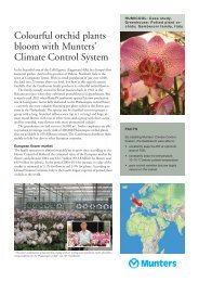
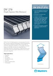
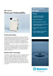
<strong>DF</strong> 2100Droplet SeparatorEQUIPMENT<strong>DF</strong> 2100• High separation efficiency• Very low pressure drop leading tolower operating costs• Corrosion resistant• Simple installation• Low maintenance cost due to simpleoperating principle and long lifetime• Wide face velocity range• Tailor made sizes and designs• Hygienic design• Wide range of highest quality material• In house ISO 9001 certified manufacturing<strong>DF</strong> 2100 is a ready-to-install droplet separator for use in many application areas.It is available in various material combinations and configurations to fit a widerange of operating conditions.<strong>DF</strong> 2100 droplet separator provides high efficiency droplet separation andlow pressure drop even at high face velocity giving energy saving operation.The droplet separator can be configured to most individual performance andinstallation situations, providing a cost effective solution. Alternative materialchoices and drainage systems, as well as add-on features like flanges and protectionmesh are just some of the configuration options.<strong>DF</strong> 2100 droplet separator is an excellent choice for keeping rain, mist andlarger fog water droplets out of a building or marine ventilation system. Thishelps to reduce corrosion, to increase filter lifetime and to reduce moisturethroughout the system. <strong>DF</strong> 2100 droplet separator is designed for use in manyapplications, for example: air intakes, condensate removal behind cooling coils,as an air straightener before spray humidifiers, in air washers etc. The unit is suitablefor use at face velocities between 2 and 6 m/s.Separation technologyThe streamlined separator deflects the droplet laden gas stream, as a result themomentum of the droplets causes them to impinge onto the profile surface. Thedroplets coalesce together and form a liquid film, the influence of gravity causesthe liquid to drain to the bottom of the profiles. Specially shaped separationchambers improve performance by enhancing the separation of finer dropletsand ensuring problem free discharge of liquid.To avoid “flooding” of the profiles and the possibility of re-entrainment of theseparated liquid, the height of the profile sections, droplet separators is normallylimited to 2,500 mm.Principle illustration.
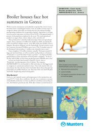
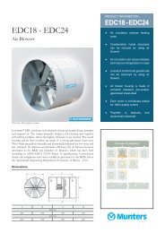
PerformanceThe limit drop size represents a performancecharacteristic of the profile, at therelevant velocity and operating conditionsit is the size of the smallest dropletthat is completely separated. The diagramshowing limit drop size has beencalculated for an air/water system at20 °C and 1 bar.The pressure drop is measured at ambientconditions (20 °C and 1 bar)through a number of assembled profilesat various pitches/spacing and underideal conditions.The fractional efficiency indicates thepercentage of droplets, removed from anairstream, that are smaller than the limitdrop size.Liquid loadMaximum liquid load; 200 gram water/kg air, measured under ideal conditionsat 20 °C, 1 bar and a face velocity of 4.5m/s with a pitch/spacing of 20 mm betweenthe profiles.Drop diameter [μm]Efficiency40353025201510500%10090807060504030201000Limit drop size <strong>DF</strong> 21001 2 3 4 5 6 7 8Face velocity [m/s]Fractional efficiency <strong>DF</strong> 2100 at 6 m/s5 10 15 20 25 30Drop diameter [μm]Pressure drop [Pa]12010080604020001Pressure drop <strong>DF</strong> 21002 3 4Face velocity [m/s]20 mm pitch/spacing between profiles25 mm pitch/spacing between profiles30 mm pitch/spacing between profilesFor any data outside the specified range, please contact yournearest <strong>Munters</strong> representative.567Type, material and dimension specificationsABCAirflow* Anodised or coloured material on request.** All frames can be painted on request (specify RAL code).All frames powder coated on request.Aluminium frames of other aluminium alloys on request.All frames can be brushed to give a frosted appearance,stainless steel can be obtained polished.*** Standard tolerance on width and height: +0, –5 mm.****Special polypropylene compound for min operating temperature–40 °C on request.Type Material Pitch/ Width*** Height*** Depth Operatingcodespacing A mm B mm C temp °CFrame ** Profilebetween profilesmm min–max min–max mm min–max1b 304 PPTVb **** 20, 25, 30 300–2,500 300–2,500 206 +5 – +1001w 304 PPTVw 20, 25, 30 300–2,500 300–2,500 206 +5 – +1002b 316L PPTVb **** 20, 25, 30 300–2,500 300–2,500 206 +5 – +1002w 316L PPTVw 20, 25, 30 300–2,500 300–2,500 206 +5 – +1003b 316Ti PPTVb **** 20, 25, 30 300–2,500 300–2,500 206 +5 – +1003w 316Ti PPTVw 20, 25, 30 300–2,500 300–2,500 206 +5 – +1004b AlMg3* PPTVb **** 20, 25, 30 300–2,500 300–2,500 206 +5 – +1004w AlMg3* PPTVw 20, 25, 30 300–2,500 300–2,500 206 +5 – +1005p AlMg3* PVC 20, 25, 30 300–2,500 300–2,500 206 -10 – +606p 316L PVC 20, 25, 30 300–2,500 300–2,500 206 -10 – +607a AlMg3* AlMgSi0.5 * 20, 25, 30 300–2,500 300–2,500 2061)–8a AlMg3* AlMgSi0.5* 20, 25, 30 300–2,500 300–2,500 1902)–9s 316Ti 316Ti 20, 25, 30 300–2,500 300–2,500 190 –PPTV = Talcum reinforced polypropylene 304 = Stainless steel (AISI 304, DIN 1.4301)(b = black, w = white) 316L = Stainless steel (AISI 316L, DIN 1.4404)PVC = Polyvinyl cloride (colour: grey) 316Ti = Stainless steel (AISI 316Ti, DIN 1.4571)AlMgSi0.5 = Aluminium alloy1) Design type one, with PPTV spacers.AlMg3 = Aluminium alloy2)Design type two, all aluminium.Drainage positionsCode for drainige position, put P before the position number, e.g., P9 or P6,8,9,10 if more outlets are to be used.FrontSideBackDrawing for fittings(see next page).BackFrontAirflowAirflowBottom1 6 7 8 59, 10, 11 1 6, 7, 8 5 9 10 11 1Ø122 3 4 2, 3, 44 3 2L~2+Ø*50 2 *Diameter of bushing, nipple or tube. Dimensions in mm.12 Slot throughout the entire bottomfor use with separate housing/tray.
Fittings specificationsFor aluminium framesTubesFitting Ø Lcode mm mmA1 16 50A2 20 50A3 30 50A4 42 50A5 54 75A6 65 75A7 76 75For stainless steel framesBushingFittingInside threads,both sides.Ø Lcode inch mmB1 1/2 34B2 3/4 36B3 1 43B4 1 1/2 48B5 2 56B6 2 1/2 70B7 3 95For stainless steel framesHalf bushing Inside threads,both sides.Fitting Ø Lcode inch mmC1 1/2 15C2 3/4 17C3 1 19C4 1 1/2 22C5 2 26For stainless steel frames ExternalWeld-on nippleFitting Øthreads, oneside.Lcode inch mmD1 1/2 35D2 3/4 40D3 1 40D4 1 1/2 50D5 2 50D6 2 1/2 60D7 3 65For stainless steel framesNipple* External threads, entiredlength.Fitting Ø Lcode inch mmE1 1/2 25E2 3/4 40E3 1 35E4 1 1/2 38E5 2 45LLLLLØØØØØFitting material AlMgSi0.5 Bushing according to DIN 2986, nipples DIN 2982, material 316Ti (AISI 316Ti, DIN 1.4571), witworth – thread according to DIN 259.aluminium alloy.* In combination with bushing (fitting code B).N.B. The required cross-section of the water outflow depends on both application and liquid load. Most frequently used fitting sizes are 3/4” and 1” and corresponding tube sizes.LeftTopBottomRightHole configurations in flanges are deliveredaccording to Eurovent, DIN24193, Norsok or other trade, nationalor international standards (specifystandard). Hole configuration accordingto individual requirements are alsodelivered (specify drill pattern and holediameter, provide drawing or usesketch on last page).[mm]Code min–maxR 50–500 RCode for radius, put R before the dimension,e.g. R150WBackCN.B. Depths [C] is the samewith or without flanges.BackProtection gridFront2 1Airflow<strong>DF</strong> 2100<strong>DF</strong> 2100 droplet separator is developed to suit a wide range ofapplications. The various outfit options cover the most typicallyoccurring installation variations. However, tailor madedroplet separators are frequently delivered based on customers’individual specifications.Material certificates can be delivered for most materialsupon request. Fractional efficiency curves for given face velocitiesare delivered on special request.For hygienic-proof HVAC equipment <strong>DF</strong> 2100 dropletseparator can be delivered in accordance with the standardsVDI 6022, VDI 3803, DIN 1946 (specify H in order code).TFrontAirflow<strong>DF</strong> 2100 is developed and produced by <strong>Munters</strong> Euroform GmbH,Germany.MeshFlanges specificationsFlange code Position Thickness*, TSpotwelded weldedcode mmF1 F11 Top & bottom front T2 2F2 F12 Left & right front T3 3F3 F13 All sides front T5 5F4 F14 Top & bottom back T8 8F5 F15 Left & right back Width*, WF6 F16 All sides back code mmF7 F17 Top & bottom, front & back W30 30F8 F18 Left & right, front & back W50 50F9 F19 All sides front & back W60 60Material: Aluminium and stainless steel in accordance with the frame material selected.* Other thickness or width on request.Protection grid and mesh type specificationsProtection Position Mesh width, S Mesh type, wiregrid codediameter, d Ø [mm]inch mm1.0 1.2 1.5 2.0G1 Front 1/4 × 1/4 5 × 5 Q1G2 Back 1/4 × 1/4 6 × 6 Q2 X21/3 × 1/3 8 × 8 Q3 X31/2 × 1/2 10 × 10 Q4 X41/2 × 1/2 12 × 12 Q5 Y5S 3/4 × 3/4 16 × 16 Q6 X6 Y63/4 × 3/4 20 × 20 Q7 Y7 Z71 × 1 25 × 25 Y8 Z8dMaterial: Stainless steel 304 (AISI 304, DIN 1.4301).N.B. Protection grid is mainly used as trash screen on airinlets. Pressure drop over wire mesh is negligible.Order information<strong>DF</strong> 2100-X-X-X-X-X-X-X-X-X-X-X-XType codePitch/spacing, mmWidth, mmHeight, mmDrainage position(s) codeFitting codeFlange position codeFlange thickness codeFlange width codeProtection grid position(s) codeMesh type codeRadius codee.g., <strong>DF</strong> 2100-1b-25-1820-1200-P9-B5-F2-T2-W30-G2-Q4-R150OptionsContinous
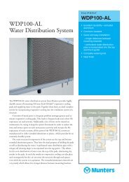
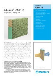
Examples of installation1. The droplet separator is flanged ontoa wall opening and the water drainsvertically outside of the wall.2. The droplet separator is flanged into awall opening and the water drainscontrolled into an internal tray (notshown in the drawing)3. The droplet separator is installed in anair duct and stands in between angledprofiles that are connected to the airduct. The water drains through thebottom into a tray that is below theair duct.1. 2. 3.Airflow Airflow AirflowWater outflow Water outflowWater outflowDrill pattern sketch<strong>Munters</strong> Europe AB, HumiCool Division, Kung Hans Väg 8, P O Box 434, SE-191 24 Sollentuna, Sweden. Phone +46/(0)8/626 63 00, Fax +46/(0)8/754 56 66.<strong>Munters</strong> Euroform GmbH, Philipsstr. 8, 52068 Aachen, PO Box 101109, 52011 Aachen, Germany. Phone +49/(0)241/89 00 0, Fax +49/(0)241/89 00 5199.www.munters.comAustria via sales organization in Germany ,<strong>Munters</strong> Euroform GmbH, Phone +49/(0)241/89 00 0, Fax +49/(0)241/89 00 5199 Denmark , via sales organization in Sweden,<strong>Munters</strong> Europe AB, Phone +46/(0)8/626 63 00, Fax +46/(0)8/754 56 66,Finland <strong>Munters</strong> Oy, Phone +358/(0)9/83 86 0330, Fax +358/(0)9/83 86 0336, France <strong>Munters</strong> France S.A., Phone +33/(0)1/34 11 57 50, Fax +33/(0)1/34 11 57 51, Germany <strong>Munters</strong> Euroform GmbH, Phone +49/(0)241/89 00 0,Fax +49/(0)241/89 00 199, Italy <strong>Munters</strong> S.R.L., Phone +39/(0)2/488 6781, Fax +39/(0)2/488 1171, <strong>Munters</strong> euroemme S.p.A., Phone +39/(0)183/52 11, Fax +39/(0)183/521 333,Kingdom of Saudi Arabia and Middle East Hawa <strong>Munters</strong>, c/o Hawa United Cooling Syst. Co. Ltd., Phone +966/(0)1/477 15 14, Fax +966/(0)1/476 09 36, Norway via sales organization in Sweden, <strong>Munters</strong> Europe AB,Phone +46/(0)8/626 63 00, Fax +46/(0)8/754 56 66, South Africa & Sub-Sahara Countries <strong>Munters</strong> (Pty) Ltd, Phone +27/(0)11/455 2550/1/2, Fax +27/(0)11/455 2553, Spain <strong>Munters</strong> Spain S.A., Phone +34/91/640 09 02,Fax +34/91/640 11 32, Sweden <strong>Munters</strong> Europe AB, Phone +46/(0)8/626 63 00, Fax +46/(0)8/754 56 66, Switzerland via sales organization in Germany, <strong>Munters</strong> Euroform GmbH, Phone +49/(0)241/89 00 0, Fax +49/(0)241/89 00 199,United Kingdom <strong>Munters</strong> Ltd, Phone +44/(0)1480/442 340, Fax +44/(0)1480/411 332, Export & Other countries <strong>Munters</strong> Europe AB Phone +46/(0)8/626 63 00, Fax +46/(0)8/754 56 66,Region Americas <strong>Munters</strong> Corporation, Phone +1/(0)978 241 1100, Fax +1/(0)978 241 1214, Region Asia <strong>Munters</strong> K.K., Phone +81/(0)3/5970 0021, Fax +81/(0)3/5970 3197HC/MMA/EqGB-0202-03/02 2000 SOS ReklamStudio<strong>Munters</strong> reserves the right to make alterations to specifications, quantities, etc., for production or other reasons, subsequent to publication.© <strong>Munters</strong> Europe AB, 2003