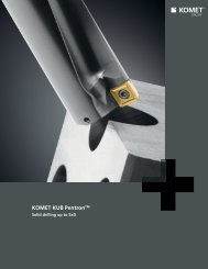
KOMPASS TOOLlife Catalog ( 18.7 MB) - Komet
KOMPASS TOOLlife Catalog ( 18.7 MB) - Komet
KOMPASS TOOLlife Catalog ( 18.7 MB) - Komet
- No tags were found...

Create successful ePaper yourself
Turn your PDF publications into a flip-book with our unique Google optimized e-Paper software.
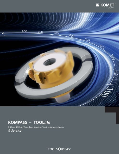
200| 900 | 800| 700 | 600t maxDrilling, Milling, Threading, Reaming, Turning, Countersinking| 500| 400| 300|| 100<strong>KOMPASS</strong> – <strong>TOOLlife</strong>& Service
KomPass TOOL lifeTools and ServiceKOMET GROUP's innovative tool designs and comprehensive boremachining solutions make it a global technology leader. You knowus as a supplier of premium tools and know the ideas behind oursolutions.In addition, we offer you a comprehensive menu of services andsupport functions.The KomPass <strong>TOOLlife</strong> tool program combines refurbishable tools fromthe KOMET GROUP product portfolio with a local KOMET SERVICE ®Partner capable of providing the appropriate services.We combine the following advantages under the <strong>TOOLlife</strong> concept:High quality, long-lasting products.Guidance from the KOMET SERVICE ® Partner and KOMET ® outsidesales representatives for optimized use of tools.A catalog with recommended cutting data and applications.The service portfolio of the KOMET SERVICE ® Partner Network.2
KomPass TOOL life – Program overviewTOOL life – Tool program 4 – 5DrillingKUB® DrillmaxKUB® Drillmax XLKUB® K26 – 271MillingSolid carbide milling cutters, end milling cutters,roughing end mills, HPC, spherical, torus, chamfer,and radius milling cutters28 – 532ThreadingMKG, MGF, UMGF, BGF, UBGF, DBGF,GWF, TOMILL CUT,DOREX, TINIB, FEDUB, FEDUC, GG, TAREX, SIREX54 – 1573ReamingReamax® TS, Reamax®Monomax®Solid carbide reamers158 – 2094TurningExternal and internal machiningUniTurn®210 – 2375Countersinking 238 – 2416KOMET SERVICE® 242 – 243Services menu Overview 244 – 2457Special tools Quote request form 246 – 2518Service partner Partner benefits 252 – 2539More informationTechnical informationNumerical index254 – 265103
KomPass TOOL life – Tool programTools that last.The KomPass <strong>TOOLlife</strong> Program offers you the full rangeof KOMET GROUP standard solid carbide and HSS tools.The program encompasses quality tools used forsolid drilling, reaming, threading, milling, turning andchamfering and that can be refurbished.You will find the KOMET GROUP's complete productofferings in these catalogs:- KomPass Bore Machining- KomPass Reaming- Threading Systems- Milling / Turning, and- Facing Heads1 Solid Drilling Page 6 – 27KUB® DrillmaxØ 3 – 16 mmKUB® Drillmax XLØ 3 – 10 mmKUB K2®Ø 10 – 20.5 mm2 Milling Page 28 – 53Please refer to our compact technicaluser guide "KomGuide" for comprehensivetechnical information such asmachining parameters, formulas andrecommended uses.End milling cutter UNIEnd milling cutter HPCEnd milling cutter XHØ 3 – 20 mmØ 6 – 20 mmØ 3 – 20 mmØ 4 – 10 mmEnd milling cutter ALØ 3 – 20 mmØ 4 – 8 mmEnd milling cutter HFØ 3 – 25 mmRoughing end millSpherical cutterSpherical cutter XHØ 6 – 20 mmØ 3 – 20 mmØ 3 – 16 mmØ 3 – 20 mmTorus milling cutter XHChamfer milling cutterØ 6 – 12 mmØ 6 – 12 mmRadius milling cutterØ 6 – 8 mm4
KOMET KUB® DrillmaxPage1Straight shank DIN 6535 HA / HE3 – 16 mm. right-hand cuttingDrilling depth 5×DDrilling depth 7-8×D8 – 910–112KOMET KUB® Drillmax XLStraight shank DIN 6535 HA3 – 10 mm. right-hand cuttingDrilling depth 20×D3 – 8 mm. right-hand cuttingDrilling depth 30×DCutting recommendationsGuideline values for solid drillingPage121314 – 1534Technical notes17567Component: bearing bracketMachining:lateral mounting holesØ 11 mm, length 60 - 75 mm8Tool: KUB® Drillmax 8×DMachining time: 15 secondsNo pilot holes requiredTool does not deviateMachining time reduced from 30 sec to 15 secHigh process reliabilityPrecise alignmentGood chip removal9107
KOMET KUB® DrillmaxØ 3.0 – 16.0 mmHigh performance solid carbide drill with straight shank DIN 6535 HA / HE, right-hand1L / D Through hole Blind hole Welded joint Slanted surface Curved surface Cross hole Center drilledholeInterrupted cut Stackplate Rough boring Adjustablediameter5×D § § $ & & & & X $ & X§ very good $ good & possible: refer to drilling technical notes. Page 17 X not possibleLlNØ dØ D140°85 × DForwork piece materialØ D Ø d × lDIN 6535 HADIN 6535 HEL N P M K N S HOrder # Order #p3.0 6 × 36 V03 03000.112730 V03 03000.212730 66 24 0.0163.1 6 × 36 V03 03100.112730 V03 03100.212730 66 24 0.0163.2 6 × 36 V03 03200.112730 V03 03200.212730 66 24 0.0173.3 6 × 36 V03 03300.112730 V03 03300.212730 66 24 0.0173.4 6 × 36 V03 03400.112730 V03 03400.212730 66 24 0.017§ $ $3.5 6 × 36 V03 03500.112730 V03 03500.212730 66 24 0.0183.6 6 × 36 V03 03600.112730 V03 03600.212730 66 24 0.0183.7 6 × 36 V03 03700.112730 V03 03700.212730 66 24 0.0183.8 6 × 36 V03 03800.112730 V03 03800.212730 74 30 0.0183.9 6 × 36 V03 03900.112730 V03 03900.212730 74 30 0.0184.0 6 × 36 V03 04000.112730 V03 04000.212730 74 30 0.0184.1 6 × 36 V03 04100.112730 V03 04100.212730 74 30 0.0194.2 6 × 36 V03 04200.112730 V03 04200.212730 74 30 0.0194.3 6 × 36 V03 04300.112730 V03 04300.212730 74 30 0.019§ $ $4.4 6 × 36 V03 04400.112730 V03 04400.212730 74 30 0.0194.5 6 × 36 V03 04500.112730 V03 04500.212730 74 30 0.0194.6 6 × 36 V03 04600.112730 V03 04600.212730 74 30 0.0194.7 6 × 36 V03 04700.112730 V03 04700.212730 74 30 0.0194.8 6 × 36 V03 04800.112730 V03 04800.212730 82 35 0.0204.9 6 × 36 V03 04900.112730 V03 04900.212730 82 35 0.0205.0 6 × 36 V03 05000.112730 V03 05000.212730 82 35 0.0205.1 6 × 36 V03 05100.112730 V03 05100.212730 82 35 0.0215.2 6 × 36 V03 05200.112730 V03 05200.212730 82 35 0.0215.3 6 × 36 V03 05300.112730 V03 05300.212730 82 35 0.0225.4 6 × 36 V03 05400.112730 V03 05400.212730 82 35 0.0225.5 6 × 36 V03 05500.112730 V03 05500.212730 82 35 0.023§ $ $5.54 6 × 36 V03 05540.112730 V03 05540.212730 82 35 0.0235.6 6 × 36 V03 05600.112730 V03 05600.212730 82 35 0.0235.7 6 × 36 V03 05700.112730 V03 05700.212730 82 35 0.0245.8 6 × 36 V03 05800.112730 V03 05800.212730 82 35 0.0245.9 6 × 36 V03 05900.112730 V03 05900.212730 82 35 0.0256.0 6 × 36 V03 06000.112730 V03 06000.212730 82 35 0.0256.1 8 × 36 V03 06100.112730 V03 06100.212730 91 43 0.0276.2 8 × 36 V03 06200.112730 V03 06200.212730 91 43 0.0276.3 8 × 36 V03 06300.112730 V03 06300.212730 91 43 0.0306.4 8 × 36 V03 06400.112730 V03 06400.212730 91 43 0.0306.5 8 × 36 V03 06500.112730 V03 06500.212730 91 43 0.032 § $ $6.6 8 × 36 V03 06600.112730 V03 06600.212730 91 43 0.0326.7 8 × 36 V03 06700.112730 V03 06700.212730 91 43 0.0326.8 8 × 36 V03 06800.112730 V03 06800.212730 91 43 0.0356.9 8 × 36 V03 06900.112730 V03 06900.212730 91 43 0.035Note: with whistle notch clamping surface per DIN 6535 HE. Minimum order quantity: 3 pieces.
5×DKOMET KUB® DrillmaxHigh performance solid carbide drill with straight shank DIN 6535 HA / HE, right-hand5 × DForwork piece materialX D X d × lDIN 6535 HADIN 6535 HEL N P M K N S HOrder # Order #p7.0 8 × 36 V03 07000.112730 V03 07000.212730 91 43 0.0377.1 8 × 36 V03 07100.112730 V03 07100.212730 91 43 0.0377.2 8 × 36 V03 07200.112730 V03 07200.212730 91 43 0.0397.3 8 × 36 V03 07300.112730 V03 07300.212730 91 43 0.0397.4 8 × 36 V03 07400.112730 V03 07400.212730 91 43 0.0407.43 8 × 36 V03 07430.112730 V03 07430.212730 91 43 0.0407.5 8 × 36 V03 07500.112730 V03 07500.212730 91 43 0.040§ $ $7.6 8 × 36 V03 07600.112730 V03 07600.212730 91 43 0.0417.7 8 × 36 V03 07700.112730 V03 07700.212730 91 43 0.0417.8 8 × 36 V03 07800.112730 V03 07800.212730 91 43 0.0437.9 8 × 36 V03 07900.112730 V03 07900.212730 91 43 0.0438.0 8 × 36 V03 08000.112730 V03 08000.212730 91 43 0.0448.1 10 × 40 V03 08100.112730 V03 08100.212730 103 49 0.0458.2 10 × 40 V03 08200.112730 V03 08200.212730 103 49 0.0458.3 10 × 40 V03 08300.112730 V03 08300.212730 103 49 0.0478.4 10 × 40 V03 08400.112730 V03 08400.212730 103 49 0.0478.5 10 × 40 V03 08500.112730 V03 08500.212730 103 49 0.0508.6 10 × 40 V03 08600.112730 V03 08600.212730 103 49 0.0508.7 10 × 40 V03 08700.112730 V03 08700.212730 103 49 0.0528.8 10 × 40 V03 08800.112730 V03 08800.212730 103 49 0.0528.9 10 × 40 V03 08900.112730 V03 08900.212730 103 49 0.0559.0 10 × 40 V03 09000.112730 V03 09000.212730 103 49 0.0559.1 10 × 40 V03 09100.112730 V03 09100.212730 103 49 0.057 § $ $9.2 10 × 40 V03 09200.112730 V03 09200.212730 103 49 0.0579.3 10 × 40 V03 09300.112730 V03 09300.212730 103 49 0.0629.4 10 × 40 V03 09400.112730 V03 09400.212730 103 49 0.0629.5 10 × 40 V03 09500.112730 V03 09500.212730 103 49 0.0679.54 10 × 40 V03 09540.112730 V03 09540.212730 103 49 0.0679.6 10 × 40 V03 09600.112730 V03 09600.212730 103 49 0.0679.7 10 × 40 V03 09700.112730 V03 09700.212730 103 49 0.0729.8 10 × 40 V03 09800.112730 V03 09800.212730 103 49 0.0729.9 10 × 40 V03 09900.112730 V03 09900.212730 103 49 0.07710.0 10 × 40 V03 10000.112730 V03 10000.212730 103 49 0.07710.1 12 × 45 V03 10100.112730 V03 10100.212730 118 56 0.08010.2 12 × 45 V03 10200.112730 V03 10200.212730 118 56 0.08510.3 12 × 45 V03 10300.112730 V03 10300.212730 118 56 0.09010.4 12 × 45 V03 10400.112730 V03 10400.212730 118 56 0.09410.5 12 × 45 V03 10500.112730 V03 10500.212730 118 56 0.09710.6 12 × 45 V03 10600.112730 V03 10600.212730 118 56 0.10010.7 12 × 45 V03 10700.112730 V03 10700.212730 118 56 0.10210.8 12 × 45 V03 10800.112730 V03 10800.212730 118 56 0.10510.9 12 × 45 V03 10900.112730 V03 10900.212730 118 56 0.10711.0 12 × 45 V03 11000.112730 V03 11000.212730 118 56 0.11011.1 12 × 45 V03 11100.112730 V03 11100.212730 118 56 0.112 § $ $11.2 12 × 45 V03 11200.112730 V03 11200.212730 118 56 0.11511.3 12 × 45 V03 11300.112730 V03 11300.212730 118 56 0.11711.4 12 × 45 V03 11400.112730 V03 11400.212730 118 56 0.12011.5 12 × 45 V03 11500.112730 V03 11500.212730 118 56 0.12211.54 12 × 45 V03 11540.112730 V03 11540.212730 118 56 0.12211.6 12 × 45 V03 11600.112730 V03 11600.212730 118 56 0.12511.7 12 × 45 V03 11700.112730 V03 11700.212730 118 56 0.12711.8 12 × 45 V03 11800.112730 V03 11800.212730 118 56 0.13011.9 12 × 45 V03 11900.112730 V03 11900.212730 118 56 0.13212.0 12 × 45 V03 12000.112730 V03 12000.212730 118 56 0.13512.5 14 × 45 V03 12500.112730 V03 12500.212730 124 60 0.18012.8 14 × 45 V03 12800.112730 V03 12800.212730 124 60 0.18013.0 14 × 45 V03 13000.112730 V03 13000.212730 124 60 0.18213.3 14 × 45 V03 13300.112730 V03 13300.212730 124 60 0.182 § $ $13.5 14 × 45 V03 13500.112730 V03 13500.212730 124 60 0.18513.8 14 × 45 V03 13800.112730 V03 13800.212730 124 60 0.18514.0 14 × 45 V03 14000.112730 V03 14000.212730 124 60 0.18814.5 16 × 48 V03 14500.112730 V03 14500.212730 133 63 0.24014.8 16 × 48 V03 14800.112730 V03 14800.212730 133 63 0.24015.0 16 × 48 V03 15000.112730 V03 15000.212730 133 63 0.25015.5 16 × 48 V03 15500.112730 V03 15500.212730 133 63 0.270§ $ $15.8 16 × 48 V03 15800.112730 V03 15800.212730 133 63 0.27016.0 16 × 48 V03 16000.112730 V03 16000.212730 133 63 0.282Other diameters available as special orders. Recommended values for solid drilling: Pages 14-15.912345678910
KOMET KUB® DrillmaxØ 3.0 – 16.0 mmHigh performance solid carbide drill with straight shank DIN 6535 HA / HE, right-hand1L / D Through hole Blind hole Welded joint Slanted surface Curved surface Cross hole Center drilledholeInterrupted cut Stackplate Rough boring Adjustablediameter7-8×D § § $ & & & & X $ & X§ very good $ good & possible: refer to drilling technical notes. Page 17 X not possibleLlNØ dØ D140°107 – 8 × DFor work piecematerialØ D Ø d × lDIN 6535 HADIN 6535 HEL N P M K N S HOrder # Order #p3.0 6 × 36 V04 03000.112730 V04 03000.212730 70 28 0.0173.1 6 × 36 V04 03100.112730 V04 03100.212730 70 28 0.0173.2 6 × 36 V04 03200.112730 V04 03200.212730 70 28 0.0173.3 6 × 36 V04 03300.112730 V04 03300.212730 70 28 0.0173.4 6 × 36 V04 03400.112730 V04 03400.212730 70 28 0.018§ $ $3.5 6 × 36 V04 03500.112730 V04 03500.212730 70 28 0.0183.6 6 × 36 V04 03600.112730 V04 03600.212730 70 28 0.0183.7 6 × 36 V04 03700.112730 V04 03700.212730 70 28 0.0183.8 6 × 36 V04 03800.112730 V04 03800.212730 80 36 0.0193.9 6 × 36 V04 03900.112730 V04 03900.212730 80 36 0.0194.0 6 × 36 V04 04000.112730 V04 04000.212730 80 36 0.0194.1 6 × 36 V04 04100.112730 V04 04100.212730 80 36 0.0204.2 6 × 36 V04 04200.112730 V04 04200.212730 80 36 0.0204.3 6 × 36 V04 04300.112730 V04 04300.212730 80 36 0.020§ $ $4.4 6 × 36 V04 04400.112730 V04 04400.212730 80 36 0.0214.5 6 × 36 V04 04500.112730 V04 04500.212730 80 36 0.0214.6 6 × 36 V04 04600.112730 V04 04600.212730 80 36 0.0214.7 6 × 36 V04 04700.112730 V04 04700.212730 80 36 0.0214.8 6 × 36 V04 04800.112730 V04 04800.212730 92 45 0.0234.9 6 × 36 V04 04900.112730 V04 04900.212730 92 45 0.0235.0 6 × 36 V04 05000.112730 V04 05000.212730 92 45 0.0245.1 6 × 36 V04 05100.112730 V04 05100.212730 92 45 0.0255.2 6 × 36 V04 05200.112730 V04 05200.212730 92 45 0.0255.3 6 × 36 V04 05300.112730 V04 05300.212730 92 45 0.0265.4 6 × 36 V04 05400.112730 V04 05400.212730 92 45 0.0275.5 6 × 36 V04 05500.112730 V04 05500.212730 92 45 0.027§ $ $5.54 6 × 36 V04 05540.112730 V04 05540.212730 92 45 0.0275.6 6 × 36 V04 05600.112730 V04 05600.212730 92 45 0.0285.7 6 × 36 V04 05700.112730 V04 05700.212730 92 45 0.0295.8 6 × 36 V04 05800.112730 V04 05800.212730 92 45 0.0305.9 6 × 36 V04 05900.112730 V04 05900.212730 92 45 0.0306.0 6 × 36 V04 06000.112730 V04 06000.212730 92 45 0.0316.1 8 × 36 V04 06100.112730 V04 06100.212730 100 52 0.0326.2 8 × 36 V04 06200.112730 V04 06200.212730 100 52 0.0346.3 8 × 36 V04 06300.112730 V04 06300.212730 100 52 0.0366.4 8 × 36 V04 06400.112730 V04 06400.212730 100 52 0.0386.5 8 × 36 V04 06500.112730 V04 06500.212730 100 52 0.039§ $ $6.6 8 × 36 V04 06600.112730 V04 06600.212730 100 52 0.0406.7 8 × 36 V04 06700.112730 V04 06700.212730 100 52 0.0416.8 8 × 36 V04 06800.112730 V04 06800.212730 100 52 0.043Note: with whistle notch clamping surface per DIN 6535 HE. Minimum order quantity: 3 pieces.
7 – 8×D KOMET KUB® DrillmaxHigh performance solid carbide drill with straight shank DIN 6535 HA / HE, right-hand7 – 8 × DFor work piecematerialØ D Ø d × lDIN 6535 HADIN 6535 HEL N P M K N S HOrder # Order #p6.9 8 × 36 V04 06900.112730 V04 06900.212730 108 60 0.0457.0 8 × 36 V04 07000.112730 V04 07000.212730 108 60 0.0457.1 8 × 36 V04 07100.112730 V04 07100.212730 108 60 0.0467.2 8 × 36 V04 07200.112730 V04 07200.212730 108 60 0.0477.3 8 × 36 V04 07300.112730 V04 07300.212730 108 60 0.0477.4 8 × 36 V04 07400.112730 V04 07400.212730 108 60 0.0487.43 8 × 36 V04 07430.112730 V04 07430.212730 108 60 0.048 § $ $7.5 8 × 36 V04 07500.112730 V04 07500.212730 108 60 0.0497.6 8 × 36 V04 07600.112730 V04 07600.212730 108 60 0.0507.7 8 × 36 V04 07700.112730 V04 07700.212730 108 60 0.0507.8 8 × 36 V04 07800.112730 V04 07800.212730 108 60 0.0517.9 8 × 36 V04 07900.112730 V04 07900.212730 108 60 0.0528.0 8 × 36 V04 08000.112730 V04 08000.212730 108 60 0.0538.1 10 × 40 V04 08100.112730 V04 08100.212730 122 68 0.0558.2 10 × 40 V04 08200.112730 V04 08200.212730 122 68 0.0578.3 10 × 40 V04 08300.112730 V04 08300.212730 122 68 0.0608.4 10 × 40 V04 08400.112730 V04 08400.212730 122 68 0.0628.5 10 × 40 V04 08500.112730 V04 08500.212730 122 68 0.0658.6 10 × 40 V04 08600.112730 V04 08600.212730 122 68 0.0678.7 10 × 40 V04 08700.112730 V04 08700.212730 122 68 0.0708.8 10 × 40 V04 08800.112730 V04 08800.212730 122 68 0.0728.9 10 × 40 V04 08900.112730 V04 08900.212730 122 68 0.0759.0 10 × 40 V04 09000.112730 V04 09000.212730 122 68 0.0779.1 10 × 40 V04 09100.112730 V04 09100.212730 130 76 0.080 § $ $9.2 10 × 40 V04 09200.112730 V04 09200.212730 130 76 0.0829.3 10 × 40 V04 09300.112730 V04 09300.212730 130 76 0.0859.4 10 × 40 V04 09400.112730 V04 09400.212730 130 76 0.0879.5 10 × 40 V04 09500.112730 V04 09500.212730 130 76 0.0909.54 10 × 40 V04 09540.112730 V04 09540.212730 130 76 0.0909.6 10 × 40 V04 09600.112730 V04 09600.212730 130 76 0.0909.7 10 × 40 V04 09700.112730 V04 09700.212730 130 76 0.0929.8 10 × 40 V04 09800.112730 V04 09800.212730 130 76 0.0959.9 10 × 40 V04 09900.112730 V04 09900.212730 130 76 0.09710.0 10 × 40 V04 10000.112730 V04 10000.212730 130 76 0.09910.1 12 × 45 V04 10100.112730 V04 10100.212730 152 90 0.10210.2 12 × 45 V04 10200.112730 V04 10200.212730 152 90 0.10510.3 12 × 45 V04 10300.112730 V04 10300.212730 152 90 0.11010.4 12 × 45 V04 10400.112730 V04 10400.212730 152 90 0.11210.5 12 × 45 V04 10500.112730 V04 10500.212730 152 90 0.11510.6 12 × 45 V04 10600.112730 V04 10600.212730 152 90 0.11710.7 12 × 45 V04 10700.112730 V04 10700.212730 152 90 0.12010.8 12 × 45 V04 10800.112730 V04 10800.212730 152 90 0.12210.9 12 × 45 V04 10900.112730 V04 10900.212730 152 90 0.12511.0 12 × 45 V04 11000.112730 V04 11000.212730 152 90 0.12711.1 12 × 45 V04 11100.112730 V04 11100.212730 152 90 0.130 § $ $11.2 12 × 45 V04 11200.112730 V04 11200.212730 152 90 0.13211.3 12 × 45 V04 11300.112730 V04 11300.212730 152 90 0.13511.4 12 × 45 V04 11400.112730 V04 11400.212730 152 90 0.13711.5 12 × 45 V04 11500.112730 V04 11500.212730 152 90 0.14011.54 12 × 45 V04 11540.112730 V04 11540.212730 152 90 0.14011.6 12 × 45 V04 11600.112730 V04 11600.212730 152 90 0.14511.7 12 × 45 V04 11700.112730 V04 11700.212730 152 90 0.15011.8 12 × 45 V04 11800.112730 V04 11800.212730 152 90 0.15511.9 12 × 45 V04 11900.112730 V04 11900.212730 152 90 0.16012.0 12 × 45 V04 12000.112730 V04 12000.212730 152 90 0.16812.5 14 × 45 V04 12500.112730 V04 12500.212730 170 106 0.19812.8 14 × 45 V04 12800.112730 V04 12800.212730 170 106 0.20013.0 14 × 45 V04 13000.112730 V04 13000.212730 170 106 0.21013.3 14 × 45 V04 13300.112730 V04 13300.212730 170 106 0.220 § $ $13.5 14 × 45 V04 13500.112730 V04 13500.212730 170 106 0.23013.8 14 × 45 V04 13800.112730 V04 13800.212730 170 106 0.24014.0 14 × 45 V04 14000.112730 V04 14000.212730 170 106 0.24614.5 16 × 48 V04 14500.112730 V04 14500.212730 192 122 0.31514.8 16 × 48 V04 14800.112730 V04 14800.212730 192 122 0.31715.0 16 × 48 V04 15000.112730 V04 15000.212730 192 122 0.32015.5 16 × 48 V04 15500.112730 V04 15500.212730 192 122 0.340§ $ $15.8 16 × 48 V04 15800.112730 V04 15800.212730 192 122 0.35016.0 16 × 48 V04 16000.112730 V04 16000.212730 192 122 0.360Other diameters available as special orders. Recommended values for solid drilling: Pages 14-15.1112345678910
KOMET KUB® Drillmax XLØ 3.0 – 10.0 mm · 20×DHigh performance solid carbide drill with straight shank DIN 6535 HA, right-hand1Caution! Always drill a pilot hole! Direct spot drilling is not possible, even on a machined spot drill surface. Angled or unmachinedspot surfaces must also be faced or spot faced for the pilot tool. (Page 16).4 guide chamfersTiAlN coatingCoolant channelsLlNØ dØ D140°20 × DForworkpiece materialØ D Ø d × lDIN 6535 HAL N P M K N S HOrder #3.0 6 × 36 V05 03000.117830 108 624.0 6 × 36 V05 04000.117830 132 824.5 6 × 36 V05 04500.117830 144 955.0 6 × 36 V05 05000.117830 156 1035.5 6 × 36 V05 05500.117830 168 1136.0 6 × 36 V05 06000.117830 178 1236.5 8 × 36 V05 06500.117830 192 1338.0 8 × 36 V05 08000.117830 222 1648.5 10 × 40 V05 08500.117830 244 1749.0 10 × 40 V05 09000.117830 256 18410.0 10 × 40 V05 10000.117830 270 205Other diameters available as special orders.§ §§ §§ §12
Ø 3.0 – 8.0 mm · 30×D KOMET KUB® Drillmax XLHigh performance solid carbide drill with straight shank DIN 6535 HA, right-handCaution! Always drill a pilot hole! Direct spot drilling is not possible, even on a machined spot drill surface. Angled or unmachinedspot surfaces must also be faced or spot faced for the pilot tool. (Page 16).4 guide chamfersTiAlN coatingCoolant channels12LlN3Ø dØ D140°430 × DForworkpiece materialØ D Ø d × lDIN 6535 HAL N P M K N S HOrder #3.0 6 × 36 V06 03000.117830 138 924.0 6 × 36 V06 04000.117830 172 1224.5 6 × 36 V06 04500.117830 189 1375.0 6 × 36 V06 05000.117830 206 1535.5 6 × 36 V06 05500.117830 223 1686.0 6 × 36 V06 06000.117830 238 1836.5 8 × 36 V06 06500.117830 257 1988.0 8 × 36 V06 08000.117830 302 244§ §§ §56Other diameters available as special orders.789Recommended values for solid drilling: Pages 14-15.1013
KOMET KUB® Drillmax, KOMET KUB® Drillmax XLCutting recommendations1Material groupStrength Rm (N/mm²)Hardness HBGuideline values for solid drillingMaterialMaterials examplesMaterial codeANSI / SAECutting speedvc (m/min)5×D / 7-8×DFeed rate f (mm/rev.)Ø 3.0-5.0 Ø 5.1-8.0min opt. max min opt. max min opt. max1.0 500Non-alloy steels: structural, case hardened,machining and cast steelA570.361213A573.8195 115 135 0.08 0.14 0.20 0.15 0.20 0.252.0500-900Non-alloy/ low alloy steels: structural, casehardened, heat treated, tool and cast steel51201055511570 85 100 0.06 0.12 0.18 0.12 0.17 0.222.1Lead alloy machining steels< 500 12L1370 85 100 0.06 0.12 0.18 0.10 0.18 0.25P3.0> 900 -1200Low alloy steels: heat resistant structural, heat 4140treated, nitride and tool steel106470 75 80 0.05 0.10 0.15 0.10 0.15 0.204.0> 1200High alloy steel: tool steelH13H2145 60 75 0.05 0.09 0.13 0.10 0.14 0.184.1High speed steel (HSS)5.0250Inconel ® 718Special alloys: Inconel, Hastelloy, Nimonic, etc.Nimonic ® 80AS5.1Titanium, titanium alloys400 AMS R545206.0 600Stainless steels304L31640 55 70 0.06 0.12 0.18 0.12 0.17 0.22M6.1< 900 Stainless steels63025 45 65 0.05 0.08 0.10 0.09 0.15 0.207.0> 900Stainless / heat proof steels42040315 30 40 0.05 0.08 0.10 0.06 0.10 0.148.0180Gray cast ironNo 35 BNo 50 B90 115 140 0.10 0.18 0.25 0.15 0.23 0.308.1250 Gray cast iron alloyA436 Type 270 95 120 0.10 0.18 0.25 0.15 0.23 0.309.0 600 130 Spheroidal graphite cast iron, ferritic 60-40-18100 120 140 0.08 0.14 0.20 0.15 0.20 0.25K9.1Spheroidal graphite cast iron,230 80-55-06ferritic / pearlitic80 100 120 0.06 0.12 0.18 0.10 0.15 0.2010.0> 600 250Spheroidal graphite cast iron, pearliticductile iron100-70-037000370 90 110 0.06 0.12 0.18 0.10 0.15 0.2010.1200 Spheroidal cast iron alloyA43D260 70 80 0.06 0.12 0.18 0.10 0.15 0.2010.2300Vermicular cast iron60 70 80 0.06 0.12 0.18 0.10 0.15 0.2012.012.1Copper alloy, brass, lead alloy bronze, lead90 bronze: good cuttability.UNS C36000100Copper alloy, brass, bronze: averagecuttabilityN13.060Wrought aluminum alloy13.114.075Cast aluminum alloy: Si content < 10%magnesium alloyGD-AlSi12100Cast aluminum alloy: Si content > 10%A360.2H15.01400Hardened steels < 45 HRC1416,01800Hardened steels> 45 HRCCutting values shown on these pages relate to the basic recommendations indicated for cutting materials.
KOMET KUB® Drillmax, KOMET KUB® Drillmax XLCutting recommendations5×D / 7-8×D 20×D / 30×DFeed rate f (mm/rev.)Feed rate f (mm/rev.)1Cutting speedØ 8.1-10.0 Ø 10.1-12.0 Ø 12.1-14.0 Ø 14.1-16.0v c (m/min)Ø 3.0-4.0 Ø 4.1-6.0 Ø 6.1-10.0min opt. max min opt. max min opt. max min opt. max min opt. max min opt. max min opt. max min opt. max20.15 0.23 0.30 0.20 0.28 0.35 0.25 0.33 0.40 0.30 0.38 0.45 40 85 100 0.06 0.10 0.15 0.10 0.20 0.30 0.15 0.25 0.350.15 0.20 0.25 0.18 0.24 0.30 0.20 0.28 0.35 0.30 0.44 0.48 40 75 100 0.06 0.09 0.12 0.10 0.17 0.25 0.15 0.20 0.250.20 0.28 0.35 0.25 0.33 0.40 0.30 0.38 0.45 0.35 0.44 0.52 40 85 100 0.06 0.10 0.15 0.15 0.25 0.30 0.15 0.25 0.3530.12 0.19 0.25 0.15 0.23 0.30 0.20 0.28 0.35 0.25 0.33 0.40 35 60 80 0.06 0.09 0.12 0.10 0.15 0.20 0.15 0.20 0.250.12 0.18 0.23 0.15 0.22 0.28 0.18 0.25 0.32 0.20 0.28 0.3540.15 0.20 0.25 0.18 0.24 0.30 0.20 0.28 0.35 0.22 0.31 0.4050.11 0.17 0.22 0.14 0.20 0.25 0.16 0.23 0.30 0.20 0.28 0.350.08 0.13 0.18 0.12 0.17 0.22 0.14 0.20 0.26 0.16 0.23 0.300.20 0.30 0.40 0.25 0.33 0.40 0.25 0.35 0.45 0.30 0.40 0.50 40 70 85 0.07 0.11 0.15 0.18 0.24 0.30 0.20 0.25 0.3560.20 0.30 0.40 0.25 0.33 0.40 0.25 0.35 0.45 0.30 0.40 0.50 40 70 85 0.07 0.11 0.15 0.18 0.24 0.30 0.20 0.25 0.350.15 0.23 0.30 0.20 0.28 0.35 0.25 0.33 0.40 0.30 0.38 0.45 35 65 80 0.06 0.10 0.15 0.15 0.20 0.25 0.15 0.25 0.300.14 0.20 0.25 0.18 0.24 0.30 0.20 0.28 0.35 0.25 0.33 0.40 35 65 80 0.06 0.10 0.15 0.15 0.20 0.25 0.15 0.25 0.300.14 0.20 0.25 0.18 0.24 0.30 0.20 0.28 0.35 0.25 0.33 0.40 35 65 80 0.06 0.10 0.15 0.15 0.20 0.25 0.15 0.25 0.3070.14 0.20 0.25 0.18 0.24 0.30 0.20 0.28 0.35 0.25 0.33 0.400.14 0.20 0.25 0.18 0.24 0.30 0.20 0.28 0.35 0.25 0.33 0.40 35 65 80 0.06 0.09 0.12 0.15 0.20 0.25 0.15 0.25 0.308910Be sure to check Chapter 10 for more application details and safety notes!15
KOMET KUB® Drillmax XL1A practical example:1. Pilot holeDrilling depth 2 to 3 × D2. Start the deep hole drillingEnter the pilot hole at reduced cutting speed vc = 20-30 m/minat the working feed rate.Just before reaching the pilot hole bottom, stop the feed andsmoothly raise the speed to the cycle speed.3. Drill the deep holeIncrease the feed to cycle speed. Drill to the required hole depth without pecking. Because of the risk ofbreakouts when drilling a through hole, the feed should be reduced by 50% when the drill tip exits.4. Backing outOn reaching the final drilling depth, draw out the tool 2 to 3 mm, then reduce the cutting speed to vc =20-30 m/min and pull back to the pilot depth at vf = 3,000 mm/min. Finally, back out of the hole at n =300 rpm and vf = 3,000 mm/min.16Please also refer to the additional user and safety instructions in Chapter 10.
5×D / 7–8×D KOMET KUB® DrillmaxTechnical notes1.Starting on uneven surfaces (cast surfaces)• reduce the feed according to the surface quality or when spot drilling12.Starting on angled surfaces• Spot face the surface before starting to drill23.Angled hole exit• Reduce feed by 50% when nearing the exit34.Starting on curved surfaces• drilling on center with reduced feed is possible• do spot facing if the bore start point lies outside the radius center45.Drilling through a cross hole• halve the feed rate when erupting56.Starting on a groove or a large centering hole• end face the groove or the center beforehand (diameter min. 0.1 mm larger than drill diameter)• possible under certain conditions, reduce feed as needed67.1 23Interrupted cut• not possible8.Starting on an edge• not possible (the starting point must be flat)79.Starting on a welded seam• spot face the surface beforehand810.Drilling through stacked plates• possible in principle• good workpiece clamping required• avoid large spaces between elements911.Rough boring• 5×D and 7-8×D possible• 20×D and 30×D not possible10Caution! Always drill a pilot hole! Direct spot drilling is not possible, even on a machined spot drill surface. Angled or unmachinedspot surfaces must also be faced or spot faced for the pilot tool.17
KOMET KUB K2®Replaceable head drill for small diameters1KOMET KUB K2® replaceable head drillWith the double-cuttingKUB K2® replaceable head system,KOMET® introduced an ingenious system of replaceablehead drills.With small drilling diameters starting from 10 mm, it letsyou take advantage of the economy and flexibility ofreplaceable cutting heads.The double-cutting carbide drill heads cannot be reground.Thanks to a patented attachment point, they are selfclamping.self-centering and easy to change.Your PLUS:User-friendly quick-change connector permits easy.secure change-out of the KUB K2® replaceableheads even in the machine.Maximum performance and optimum feedthanks to the latest coatings and high-end radiallands.Optimized flutes provide outstanding chip removalfor all materials.Special surface treatment provides maximumperformance and base element life.Rotating applicationin a machining centerMaterial: 1.4571, V4Avc = 70 m/min · f = 0.2 mm/revStationary applicationin a cyclically-controlled latheMaterial: 42CrMo4vc = 90 m/min · f = 0.22 mm/rev18
KOMET KUB K2®Straight shank ISO 9766Ø 10 – 20.5 mm. right-hand cutDrilling depth 3×D, 5×D, 7×DPage20 – 251Cutting recommendationsRecommended values for solid drilling262Technical notes2734Applications:- For diameter range 10 to 20.5 mm- Internal coolant supply- Suitable for use with steel, cast metal andstainless materials- Replaceable head system makes it possibleto use a wide variety of lands and coatings.567Rotating applicationin a machining centerMaterial: 1.6758 (23MnNiMoCr5-4)vc = 46 m/min · f = 0.1 mm/revPlease note: Use of the KUB K2® in a hydraulic expansionchuck requires a reduction sleeve.89Ø 20, Ø 25, Ø 32Ø 12, Ø 16, Ø 201019
KOMET KUB K2®Ø 10.0 – 12.9 mmReplaceable head drill with straight shank similar to ISO 9766, right-hand1lLNaØ d140°Ø D +0.05BK8425Replaceable headBK2725CoatingForworkpiece materialØ D Order # Order #a P M K N S H10.0 H70 10000.018425 H70 10000.01272510.1 H70 10100.018425 H70 10100.01272510.2 H70 10200.018425 H70 10200.01272510.3 H70 10300.018425 H70 10300.01272510.4 H70 10400.018425 H70 10400.01272510.5 H70 10500.018425 H70 10500.01272510.6 H70 10600.018425 H70 10600.01272510.7 H70 10700.018425 H70 10700.01272510.8 H70 10800.018425 H70 10800.01272510.9 H70 10900.018425 H70 10900.01272511.0 H70 11000.018425 H70 11000.01272511.1 H70 11100.018425 H70 11100.01272511.2 H70 11200.018425 H70 11200.01272511.3 H70 11300.018425 H70 11300.01272511.4 H70 11400.018425 H70 11400.01272511.5 H70 11500.018425 H70 11500.01272511.6 H70 11600.018425 H70 11600.01272511.7 H70 11700.018425 H70 11700.01272511.8 H70 11800.018425 H70 11800.01272511.9 H70 11900.018425 H70 11900.01272512.0 H70 12000.018425 H70 12000.01272512.1 H70 12100.018425 H70 12100.01272512.2 H70 12200.018425 H70 12200.01272512.3 H70 12300.018425 H70 12300.01272512.4 H70 12400.018425 H70 12400.01272512.5 H70 12500.018425 H70 12500.01272512.6 H70 12600.018425 H70 12600.01272512.7 H70 12700.018425 H70 12700.01272512.8 H70 12800.018425 H70 12800.01272512.9 H70 12900.018425 H70 12900.0127254.00 0.0044.00 0.0044.18 0.0054.18 0.0054.87 0.0064.87 0.007BK8425BK2725BK8425BK2725BK8425BK2725BK8425BK2725BK8425BK2725BK8425BK2725§§$ §§§$ §§§$ §§§$ §§§$ §§§$ §For other diameters, see following page.Includes:Replaceable head with mounting key. Please order base element and accessories separately.20Patents pending (KUB K2)
3×D / 5×D / 7×D KOMET KUB K2®Replaceable head drill with straight shank similar to ISO 9766, right-handL / D Through hole Blind hole Weld seam Slanted surface Curved surface Cross hole Center drilledhole3×D § § & & X X § X § X X5×D § § & & X X § X § X X7×D* § § & & X X § X § X X§ very good $ good & possible: see technical notes., page 27 X not possible* Be sure to check the technical information on page 27, item 15.Interrupted cut Stackplates RoughboringAdjustablediameter12Base elementAccessories3×D 5×D 7×DMulti-keyStraightshankØ d × l Order # L N Order # L N Order # L NOrder #12 × 45 U53 21000 56.6 33 0.05 U55 21000 78.6 55 0.055 U57 21000 100.6 77 0.063412 × 45 U53 21050 56.6 33 0.05 U55 21050 78.6 55 0.057 U57 21050 100.6 77 0.0655L05 10010Size 112 × 45 U53 21100 60.7 36 0.054 U55 21100 84.7 60 0.062 U57 21100 108.7 84 0.07612 × 45 U53 21150 60.7 36 0.055 U55 21150 84.7 60 0.064 U57 21150 108.7 84 0.075716 × 48 U53 31200 66.7 39 0.09 U55 31200 92.7 65 0.10 U57 31200 1<strong>18.7</strong> 91 0.111L05 10020Size 2816 × 48 U53 31250 66.7 39 0.09 U55 31250 92.7 65 0.10 U57 31250 1<strong>18.7</strong> 91 0.115®Order #ShankDrilling depthDrilling range910Recommended values for solid drilling: see page 26.21
KOMET KUB K2®Ø 13.0 – 16.9 mmReplaceable head drill with straight shank similar to ISO 9766, right-hand1lLNaØ d140°Ø D +0.05BK8425Replaceable headBK2725CoatingForworkpiece materialØ D Order # Order #a P M K N S H13.0 H70 13000.018425 H70 13000.01272513.1 H70 13100.018425 H70 13100.01272513.2 H70 13200.018425 H70 13200.0127252213.3 H70 13300.018425 H70 13300.01272513.4 H70 13400.018425 H70 13400.01272513.5 H70 13500.018425 H70 13500.01272513.6 H70 13600.018425 H70 13600.01272513.7 H70 13700.018425 H70 13700.01272513.8 H70 13800.018425 H70 13800.01272513.9 H70 13900.018425 H70 13900.01272514.0 H70 14000.018425 H70 14000.01272514.1 H70 14100.018425 H70 14100.01272514.2 H70 14200.018425 H70 14200.01272514.3 H70 14300.018425 H70 14300.01272514.4 H70 14400.018425 H70 14400.01272514.5 H70 14500.018425 H70 14500.01272514.6 H70 14600.018425 H70 14600.01272514.7 H70 14700.018425 H70 14700.01272514.8 H70 14800.018425 H70 14800.01272514.9 H70 14900.018425 H70 14900.01272515.0 H70 15000.018425 H70 15000.01272515.1 H70 15100.018425 H70 15100.01272515.2 H70 15200.018425 H70 15200.01272515.3 H70 15300.018425 H70 15300.01272515.4 H70 15400.018425 H70 15400.01272515.5 H70 15500.018425 H70 15500.01272515.6 H70 15600.018425 H70 15600.01272515.7 H70 15700.018425 H70 15700.01272515.8 H70 15800.018425 H70 15800.01272515.9 H70 15900.018425 H70 15900.01272516.0 H70 16000.018425 H70 16000.01272516.1 H70 16100.018425 H70 16100.01272516.2 H70 16200.018425 H70 16200.01272516.3 H70 16300.018425 H70 16300.01272516.4 H70 16400.018425 H70 16400.01272516.5 H70 16500.018425 H70 16500.01272516.6 H70 16600.018425 H70 16600.01272516.7 H70 16700.018425 H70 16700.01272516.8 H70 16800.018425 H70 16800.01272516.9 H70 16900.018425 H70 16900.012725For other diameters see following page.5.05 0.0085.23 0.0105.41 0.0126.09 0.014BK8425BK2725BK8425BK2725BK8425BK2725BK8425BK2725§§$ §§§$ §§§$ §§§$ §Patents pending (KUB K2)
3×D / 5×D / 7×D KOMET KUB K2®Replaceable head drill with straight shank similar to ISO 9766, right-handL / D Through hole Blind hole Weld seam Slanted surface Curved surface Cross hole Center drilledhole3×D § § & & X X § X § X X5×D § § & & X X § X § X X7×D* § § & & X X § X § X X§ very good $ good & possible: see technical notes, page 27 X not possible* Note: See technical notes page 27, item 15.Base element3×D 5×D 7×DInterrupted cut Stackplates RoughboringIncludes: Replaceable head with mounting key. Please order base element and accessories separately.StraightshankØ d × l Order # L N Order # L N Order # L NOrder #AdjustablediameterAccessoriesMulti-key123416 × 48 U53 31300 70.8 42 0.10 U55 31300 98.8 70 0.11 U57 31300 126.8 98 0.1235616 × 48 U53 31400 74.9 45 0.10 U55 31400 104.9 75 0.12 U57 31400 134.8 105 0.137L05 10020Size 2716 × 48 U53 31500 78.9 48 0.11 U55 31500 110.9 80 0.13 U57 31500 142.9 112 0.1548920 × 50 U53 41600 85.5 51 0.17 U55 41600 119.5 85 0.19 –10Recommended values for solid drilling: see page 26.23
KOMET KUB K2®Ø 17.0 – 20.5 mmReplaceable head drill with straight shank similar to ISO 9766, right-hand1lLNaØ d140°Ø D +0.05BK8425Replaceable headBK2725CoatingForworkpiece materialØ D Order # Order #a P M K N S H17.0 H70 17000.018425 H70 17000.01272517.1 H70 17100.018425 H70 17100.01272517.2 H70 17200.018425 H70 17200.01272517.3 H70 17300.018425 H70 17300.01272517.4 H70 17400.018425 H70 17400.01272517.5 H70 17500.018425 H70 17500.01272517.6 H70 17600.018425 H70 17600.01272517.7 H70 17700.018425 H70 17700.01272517.8 H70 17800.018425 H70 17800.01272517.9 H70 17900.018425 H70 17900.01272518.0 H70 18000.018425 H70 18000.01272518.1 H70 18100.018425 H70 18100.01272518.2 H70 18200.018425 H70 18200.01272518.3 H70 18300.018425 H70 18300.01272518.4 H70 18400.018425 H70 18400.01272518.5 H70 18500.018425 H70 18500.01272518.6 H70 18600.018425 H70 18600.012725<strong>18.7</strong> H70 18700.018425 H70 18700.01272518.8 H70 18800.018425 H70 18800.01272518.9 H70 18900.018425 H70 18900.01272519.0 H70 19000.018425 H70 19000.01272519.1 H70 19100.018425 H70 19100.01272519.2 H70 19200.018425 H70 19200.01272519.3 H70 19300.018425 H70 19300.01272519.4 H70 19400.018425 H70 19400.01272519.5 H70 19500.018425 H70 19500.01272519.6 H70 19600.018425 H70 19600.01272519.7 H70 19700.018425 H70 19700.01272519.8 H70 19800.018425 H70 19800.01272519.9 H70 19900.018425 H70 19900.01272520.0 H70 20000.018425 H70 20000.01272520.1 H70 20100.018425 H70 20100.01272520.2 H70 20200.018425 H70 20200.01272520.3 H70 20300.018425 H70 20300.01272520.4 H70 20400.018425 H70 20400.01272520.5 H70 20500.018425 H70 20500.0127256.28 0.0176.46 0.0206.73 0.023BK8425BK2725BK8425BK2725BK8425BK2725§§$ §§§$ §§§$ §Includes: Replaceable head with mounting key. Please order base element and accessories separately.24Patents pending (KUB K2)
3×D / 5×D KOMET KUB K2®Replaceable head drill with straight shank similar to ISO 9766, right-handL / D Through hole Blind hole Weld seam Slanted surface Curved surface Cross hole Center drilledhole3×D § § & & X X § X § X X5×D § § & & X X § X § X X§ very good $ good & possible: see technical notes., page 27 X not possibleInterrupted cut Stackplates RoughboringAdjustablediameter12Base elementAccessories3×D 5×DMulti-keyStraightshankØ d × l Order # L N Order # L NOrder #3420 × 50 U53 41700 89.5 54 0.18 U55 41700 125.5 90 0.215620 × 50 U53 41800 93.7 57 0.19 U55 41800 131.7 95 0.23L05 10020Size 27820 × 50 U53 41900 97.7 61.5 0.21 U55 41900 137.7 102.5 0.25910Recommended values for solid drilling: see page 26.25
KOMET KUB K2®Ø 10.0 – 20.5 mmCutting recommendations1Material groupStrength Rm (N/mm²)Hardness HBMaterialMaterialsexamplesMaterialcode/ANSI/SAEvc (m/min)f (mm/U)Cutting speedFeed3×D / 5×D 7×DBK8425 BK272510–20.5 10–159min opt. max min opt. max min opt. max min opt. max1.05002.0500-900Non-alloy steels:A570.36structural, case1213hardened, machiningand castA573.81steelNon-alloy/ lowalloy steels:structural, casehardened, heattreated, tool andcast steel512010555115100 120 140 0.15 0.18 0.22 0.16 0.18 0.20100 120 140 100 120 140 0.15 0.20 0.25 0.15 0.18 0.22P2.19004.0>9004.15.05.1400250Low alloy steels:heat resistant4140structural, heat1064treated, nitride and70 90 110 70 90 110 0.20 0.25 0.30 0.18 0.22 0.28tool steelHigh alloy steel:H13tool steelH21 50 70 90 50 70 90 0.15 0.20 0.25 0.14 0.18 0.22High speed steel(HSS)Special alloys:Inconel, Hastelloy,Nimonic, etc.Titanium, titaniumalloysInconel ® 718Nimonic ® 80AAMS R545206.0600Stainless steels304L316 40 60 80 0.15 0.20 0.25 0.12 0.15 0.18M6.1900180250Stainless steels 630 30 50 70 0.18 0.20 0.22 0.12 0.15 0.18Stainless / heatproof steelsGray cast iron420403 30 50 70 0.18 0.18 0.20 0.12 0.14 0.16No 35 BNo 50 B 70 90 110 0.20 0.30 0.40 0.20 0.28 0.38Gray cast iron alloy A436 Type 2 60 80 100 0.20 0.30 0.40 0.20 0.28 0.38K9.1 9.060010.0>600130230250Spheroidalgraphite cast iron,ferritic60-40-18 60 80 100 0.25 0.35 0.45 0.20 0.30 0.40Spheroidal graphitecast iron,ferritic / pearlitic80-55-06 50 70 90 0.25 0.35 0.45 0.20 0.30 0.40Spheroidal 100-70-03graphite cast iron,50 70 90 0.25 0.35 0.45 0.20 0.30 0.40pearliticductile iron 7000310.1200Spheroidal castiron alloyA43D2 30 50 70 0.20 0.25 0.35 0.18 0.22 0.30HN15.0 14.0 13.1 13.0 12.1 12.0 10.2140016.01800100 75 60 100 90 300Vermicular castiron 40 60 80 0.25 0.35 0.45 0.20 0.30 0.40Copper alloy,brass, lead alloybronze, lead UNS C36000bronze: goodcuttability.Copper alloy,brass, bronze: averagecuttabilityWrought aluminumalloyCast aluminumalloy: Si content< 10%magnesium alloyCast aluminumalloy: Si content> 10%Hardened steels 45 HRCGD-AlSi12A360.2Cutting values shown on these pages relate to the basic recommendations indicated for cutting materials.26Patents pending (KUB K2)
3×D / 5×D / 7×D1.2.3.4.5.6.1 27.38.9.10.11.12.13.14.15.KOMET KUB K2®Technical notesStarting on uneven surfaces (cast surfaces)• depending on the quality of the surface or when spot drilling, reduce the feedStarting on angled surfaces• spot face surface before starting boreAngled hole exit• reduce feed by 50 % in the exit areaStarting on curved surfaces• not possibleDrilling through a cross hole• not possibleStarting on a groove or large centering hole• end face the seam or center beforehand where applicable (diameter min. 0.1 mm greater than drilldiameter)• possible under certain conditions, reduce feed as needed.Drilling into an interrupted cut• not possibleStarting on an edge• not possible (start point must be flat)Starting on a welded seam• spot face the surface beforehandDrilling through stacked plates• possible in principle• good workpiece clamping required• avoid large spaces between elementsRough boring• not possibleCoolant• internal coolant supply, min. 5 barRotating application• max. concentricity in rotating application 0.05 mmStationary application• max. offset in stationary application 0.025 mmDFor base element > 5×D, a pilot hole with a depth of approx. 1×D is recommended2 ±11-4 mm12345678910Be sure to check Chapter 10 for more application details and safety notes!27
JEL® solid carbide milling cuttersThe new solid carbide milling cutter rangeprovides tools to meet all demands in the 3.0 -25.0 mm diameter range.JEL® solid carbide milling cuttersPageProgram overview 30 – 311For use in cast iron and steel materials; softand hard machining (up to 65 HRC); and inmold and die making.This product range encompasses tools foraluminum and non-ferrous materials.Universal useEnd milling cutter UNI Ø 3 – 20 mmEnd milling cutter UNI Ø 6 – 20 mm (long)End milling cutter Ø 3 – 20 mm (corner radius)Spherical cutter Ø 3 – 20 mm323341382Your PLUS:Comprehensive standard product rangefrom stockPerfectly tuned grade profile andcoating suited to all workpiecematerials for high productivityOriginal regrinding service andrecoating service by a comprehensivenetwork of professional KOMETSERVICE® partnersVersions:End milling cutter, roughing end mill,HPC milling cutter, spherical cutter,torus milling cutter, chamfer milling cutter,radius milling cutterRoughingRoughing end mill w. cord profile Ø 6 -20 mm 37Roughing and finishingEnd milling cutter HPC Ø 6 - 20 mm 34Copy millingTorus milling cutter XH 6 - 20 mm 44Chamfer millingChamfer milling cutter Ø 6 - 12 mm 45Chamfering and deburringRadius milling cutter Ø 6 - 8 mm 46Machining hardened steel (HRC46-56)End milling cutter XH Ø 3 - 20 mm 35End milling cutter XH Ø 4 - 10 mm (corner rad.) 42Machining hardened steel (HRC50-65)End milling cutter XH Ø 6 – 16 mmEnd milling cutter XH Ø 6 – 10 mm (corner rad.)End milling cutter XH Ø 3 – 16 mm (corner rad.)Spherical cutter XH Ø 6 – 16 mm (spherical)3643394034567Machining aluminumEnd milling cutter AL Ø 3 – 20 mmEnd milling cutter HF Ø 6 – 25 mm47488Machining aluminum and plasticEnd milling cutter AL Ø 4 – 8 mm 499Technical notesGuideline values for milling 50 – 511029
JEL® Solid carbide milling cuttersOverview12Material Group1.1Strength Rm (N/mm²)Hardness HBTypeDiameter# of teethShankCoatingFacetCorner radiusPageMaterialEnd milling cutterUNIEnd milling cutterUNIEnd milling cutterHPCEnd milling cutter End milling cutterXHXHRoughing endmillSpherical cutterØ 3– 20 mm Ø 6 – 20 mm Ø 6 – 20 mm Ø 3 – 20 mm Ø 6 – 16 mm Ø 6 – 20 mm Ø 3 – 20 mm2 – 4 2 – 4 4 4 – 8 6 – 16 4 2 – 4DIN 6535 HB DIN 6535 HB DIN 6535 HB DIN 6535 HA DIN 6535 HA DIN 6535 HB DIN 6535 HBTiAlN TiAlN TiAlN AlTiN AlTiN TiAlN TiAlN0.05-0.35 mm 0.1-0.35 mm 0.2-0.5 mm 0.05-0.2 mm – 0.5-1.0 mm –– – – – – – 1.5-10.0 mm32 33 34 35 36 37 38≤400 ≤120 Magnetic soft iron§ § § $ $ § §HP2.1 1.8 1.7 1.6 1.5 1.4 1.3 1.2M3.3 3.2 3.1 2.3 2.2NSK7.5 7.4 7.3 7.2 7.1 6.4 6.3 6.2 6.1 5.3 5.2 5.1 4.3 4.2 4.1 3.7 3.6 3.5 3.4≤700 ≤200 Structural, case hardened steel§ § § $ $ § §≤850 ≤250 Carbon steel§ § § $ $ § §≤850 ≤250 Alloy steel§ § § $ $ § §>850≤1200 >250 Alloy/heat treated steel§ § § $ $ § §≤350>1200 >350 Alloy/heat treated steel§ § § $ $ § §≤1400 ≤400 Hardened steel to 56 HRC§ §≤2200 ≤600 Hardened steel to 65 HRC$ §≤850 ≤250 Stainless steel, sulphuretted$ $ $ $ $≤850 ≤250 Austentic$ $ $ $ $≤1000 ≤300 Ferritic, ferritic & austentic, martensitic $ $ $ $ $≤500 ≤150 Grey cast iron§ § § § §>500≤1000 >150≤300Grey cast iron, heat treated§ § § § §400- 200-500 250Vermicular cast iron§ § § § §≤700 ≤200 Spheroidal graphite cast iron§ § § § §>700≤1000>200≤300Spheroidal graphite cast iron,heat treated§ § § § §≤700 ≤200 Malleable iron§ § § § §>700200≤300Malleable iron, heat treated§ § § § §≤700 ≤200 Pure titanium$ $ $ $ $≤900 ≤270 Titanium alloys$ $ $ $ $>900≤1250 >270≤300Titanium alloys$ $ $ $ $≤500 ≤150 Pure nickel$ $ $ $ $≤900 900≤1200 >270≤350Nickel alloys, high heat resistant$ $ $ $ $≤350 ≤100 Non-alloy copper$ $ $ $ $≤700 ≤200 Short chip, brass, bronze, red brass$ $ $ $ $≤700 ≤200 Long chip brass$ $ $ $ $≤500 ≤470 Cu-Al-Fe alloy (Ampco)$ $ $ $ $≤350 ≤100 Al, Mg non-alloy$ $ $ $ $≤600 ≤180Al wrought alloy,breaking strain (A5)
JEL® Solid carbide milling cuttersOverviewSpherical cutterXHSpherical cutterXHEnd millingcutterEnd millingcutter XHEnd millingcutter XHTorus millingcutter XHChamfer millingcutterRadius millingcutterØ 3 – 16 mm Ø 6 – 16 mm Ø 3 – 20 mm Ø 4 – 10 mm Ø 6 – 10 mm Ø 6 – 12 mm Ø 6 – 12 mm Ø 6 – 8 mm Ø 3 – 20 mm Ø 6 – 25 mm Ø 4 – 8 mm2 2 – 4 2 – 4 2 – 4 6 2 3 – 4 4 2 – 3 2 1DIN 6535 HA DIN 6535 HA DIN 6535 HA/HB DIN 6535 HA DIN 6535 HA DIN 6535 HA DIN 6535 HB DIN 6535 HB DIN 6535 HB DIN 6535 HA DIN 6535 HAAlTiN AlTiN TiAlN AlTiN AlTiN AlTiN TiAlN TiAlN TiAlN TiB2 TiAlN– – – – – – – – – – –1.5-8.0 mm 3.0-8.0 mm 0.5-2.0 mm 0.5-2.0 mm 0.3-1.0 mm 1.5-3.0 mm 0.5-6.0 mm – – –39 40 41 42 43 44 45 46 47 48 49$ $ § $ $ $ § §End millingcutter ALEnd millingcutter HFEnd millingcutter AL12$ $ § $ $ $ § §$ $ § $ $ $ § §$ $ § $ $ $ § §$ $ § $ $ $ § §3$ $ § $ $ $ § §§ § § § §§ § $ § $$ $ $$ $ $4$ $ $§ § §§ § §§ § §5§ § §§ § §§ § §§ § §6$ $ $$ $ $$ $ $$ $ $$ $ $7$ $ $$ § § § §$ § § § §$ § § § §8$ § § § §$ § § § § §$ § § § § §$ § § § § §$ § § § § §9$ § § § § §$ § § § §$ § § § §$ § § § §1031
JEL® UNIØ 3 – 20 mmEnd milling cutter for universal use1Shank design Helix angle Milling direction Material hardness # of teethZ30°CoatingF n < 48 HRC 2 / 3 / 4 TiAlN2F n × 45°Ø d1Ø d2l2l1Z = 2Ø d1 h10 Ø d2 h6 l1 l2 FnDescription Order #3 6 57 8 0.05 End milling cutter UNI 3.0 NZ2 30° short TiAlN 709001570203004 6 57 11 0.05 End milling cutter UNI 4.0 NZ2 30° short TiAlN 709001570204005 6 57 13 0.05 End milling cutter UNI 5.0 NZ2 30° short TiAlN 709001570205006 6 57 13 0.10 End milling cutter UNI 6.0 NZ2 30° short TiAlN 709001570206008 8 63 19 0.15 End milling cutter UNI 8.0 NZ2 30° short TiAlN 7090016302080010 10 72 22 0.20 End milling cutter UNI 10.0 NZ2 30° short TiAlN 7090017202100012 12 82 26 0.25 End milling cutter UNI 12.0 NZ2 30° short TiAlN 7090018202120014 14 82 26 0.30 End milling cutter UNI 14.0 NZ2 30° short TiAlN 7090018202140016 16 92 32 0.30 End milling cutter UNI 16.0 NZ2 30° short TiAlN 7090019202160018 18 92 32 0.35 End milling cutter UNI 18.0 NZ2 30° short TiAlN 7090019202180020 20 105 38 0.35 End milling cutter UNI 20.0 NZ2 30° short TiAlN 70900105022000Z = 33 6 57 8 0.05 End milling cutter UNI 3.0 NZ3 30° short TiAlN 709011570303004 6 57 11 0.05 End milling cutter UNI 4.0 NZ3 30° short TiAlN 709011570304005 6 57 13 0.05 End milling cutter UNI 5.0 NZ3 30° short TiAlN 709011570305006 6 57 13 0.10 End milling cutter UNI 6.0 NZ3 30° short TiAlN 709011570306008 8 63 19 0.15 End milling cutter UNI 8.0 NZ3 30° short TiAlN 7090116303080010 10 72 22 0.20 End milling cutter UNI 10.0 NZ3 30° short TiAlN 7090117203100012 12 82 26 0.25 End milling cutter UNI 12.0 NZ3 30° short TiAlN 7090118203120014 14 82 26 0.30 End milling cutter UNI 14.0 NZ3 30° short TiAlN 7090118203140016 16 92 32 0.30 End milling cutter UNI 16.0 NZ3 30° short TiAlN 7090119203160018 18 92 32 0.35 End milling cutter UNI 18.0 NZ3 30° short TiAlN 7090119203180020 20 105 38 0.35 End milling cutter UNI 20.0 NZ3 30° short TiAlN 70901105032000Z = 43 6 57 8 0.05 End milling cutter UNI 3.0 NZ4 30° short TiAlN 709021570403004 6 57 11 0.05 End milling cutter UNI 4.0 NZ4 30° short TiAlN 709021570404005 6 57 13 0.05 End milling cutter UNI 5.0 NZ4 30° short TiAlN 709021570405006 6 57 13 0.10 End milling cutter UNI 6.0 NZ4 30° short TiAlN 709021570406008 8 63 19 0.15 End milling cutter UNI 8.0 NZ4 30° short TiAlN 7090216304080010 10 72 22 0.20 End milling cutter UNI 10.0 NZ4 30° short TiAlN 7090217204100012 12 82 26 0.25 End milling cutter UNI 12.0 NZ4 30° short TiAlN 7090218204120014 14 82 26 0.30 End milling cutter UNI 14.0 NZ4 30° short TiAlN 7090218204140016 16 92 32 0.30 End milling cutter UNI 16.0 NZ4 30° short TiAlN 7090219204160018 18 92 32 0.35 End milling cutter UNI 18.0 NZ4 30° short TiAlN 7090219204180020 20 105 38 0.35 End milling cutter UNI 20.0 NZ4 30° short TiAlN 7090210504200032
Ø 6 – 20 mmJEL® UNIEnd milling cutter for universal useShank design Helix angle Milling direction Material hardness # of teethZF n30°45°CoatingF n < 48 HRC 2 / 4 TiAlN1Fn × 45°2Short versionØ d1Ø d2l2l13Fn × 45°Long versionwith neck grooveØ d1Ø d3Ø d24l2l3l15Z = 2 35°Ø d1 h10 Ø d2 h6 Ø d3 l1 l2 l3 F nDescription Order #6 6 – 50 15 – 0.10 End milling cutter UNI 6.0 NZ2 35° short TiAlN 709031500206006 6 5.8 75 24 39 0.10 End milling cutter UNI 6.0 NZ2 35° long TiAlN 709031750206008 8 – 60 20 – 0.15 End milling cutter UNI 8.0 NZ2 35° short TiAlN 709031600208008 8 7.7 75 32 39 0.15 End milling cutter UNI 8.0 NZ2 35° long TiAlN 7090317502080010 10 – 75 25 – 0.20 End milling cutter UNI 10.0 NZ2 35° short TiAlN 7090317502100010 10 9.6 100 40 60 0.20 End milling cutter UNI 10.0 NZ2 35° long TiAlN 70903100021000Z = 4 45°6 6 – 50 15 – 0.10 End milling cutter UNI 6.0 NZ4 45° short TiAlN 709041500406006 6 5.8 75 24 39 0.10 End milling cutter UNI 6.0 NZ4 45° long TiAlN 709041750406008 8 – 60 20 – 0.15 End milling cutter UNI 8.0 NZ4 45° short TiAlN 709041600408008 8 7.7 75 32 39 0.15 End milling cutter UNI 8.0 NZ4 45° long TiAlN 7090417504080010 10 – 75 25 – 0.20 End milling cutter UNI 10.0 NZ4 45° short TiAlN 7090417504100010 10 9.6 100 40 60 0.20 End milling cutter UNI 10.0 NZ4 45° long TiAlN 7090410004100012 12 – 82 26 – 0.25 End milling cutter UNI 12.0 NZ4 45° short TiAlN 7090418204120012 12 11.6 105 48 60 0.25 End milling cutter UNI 12.0 NZ4 45° long TiAlN 7090410504120014 14 – 82 26 – 0.30 End milling cutter UNI 14.0 NZ4 45° short TiAlN 7090418204140016 16 – 92 32 – 0.30 End milling cutter UNI 16.0 NZ4 45° short TiAlN 7090419204160018 18 – 92 32 – 0.35 End milling cutter UNI 18.0 NZ4 45° short TiAlN 7090419204180020 20 – 105 38 – 0.35 End milling cutter UNI 20.0 NZ4 45° short TiAlN 709041050420006789For milling guideline values see pages 50 - 511033
JEL® HPCØ 6 – 20 mmEnd milling cutter for roughing and finishing1235°/38°F n < 44 HRC 4 TiAlNLow-vibration thanks to the uneven helix angle of 35°/38°Two front cutting edges that cut as far as the centerFn × 45°Ø d1Ø d2l2l1Z = 4Ø d1 h10 Ø d2 h6 l1 l2 F nDescriptionOrder #6 6 57 13 0.2 End milling cutter HPC 6.0 NZ4 35-38° TiAlN 709061570406008 8 63 19 0.2 End milling cutter HPC 8.0 NZ4 35-38° TiAlN 7090616304080010 10 72 22 0.3 End milling cutter HPC 10.0 NZ4 35-38° TiAlN 7090617204100012 12 83 26 0.3 End milling cutter HPC 12.0 NZ4 35-38° TiAlN 7090618304120014 14 83 26 0.3 End milling cutter HPC 14.0 NZ4 35-38° TiAlN 7090618304140016 16 92 32 0.4 End milling cutter HPC 16.0 NZ4 35-38° TiAlN 7090619204160020 20 104 38 0.5 End milling cutter HPC 20.0 NZ4 35-38° TiAlN 7090610404200034
Ø 3 – 20 mmJEL® XHEnd milling cutter for finish machining on hardened steelShank design Helix angle Milling direction Material hardness # of teethZ50°F n< 46-56HRCCoating4 / 6 / 8 AlTiN12Fn × 45°3Ø d1Ø d2l2l145Z = 4Ø d1 h10 Ø d2 h6 l1 l2 FnDescription Order #3 6 50 4 – End milling cutter ØH 3.0 NZ4 50° short AlTiN 789102500403004 6 50 5 – End milling cutter ØH 4.0 NZ4 50° short AlTiN 78910250040400Z = 66 6 57 13 – End milling cutter ØH 6.0 NZ6 50° short AlTiN 789102570606008 8 63 19 – End milling cutter ØH 8.0 NZ6 50° short AlTiN 7891026306080010 10 72 22 0.1 End milling cutter ØH 10.0 NZ6 50° short AlTiN 7891027206100012 12 82 26 0.1 End milling cutter ØH 12.0 NZ6 50° short AlTiN 78910282061200Z = 816 16 92 32 0.2 End milling cutter ØH 16.0 NZ8 50° short AlTiN 7891029208160018 18 92 32 0.2 End milling cutter ØH 18.0 NZ8 50° short AlTiN 7891029208180020 20 105 38 0.2 End milling cutter ØH 20.0 NZ8 50° short AlTiN 789102050820006789For milling guideline values see pages 50 - 511035
JEL® XHØ 6 – 16 mm1End milling cutter for finish machining on hardened steelShank design Helix angle Milling direction Material hardness # of teethZ30°F n< 50-65HRC6 / 8 / 1012 / 16CoatingAlTiN2Ø d1Ø d2l2l1Z = 6 - 16Ø d1 h10 Ø d2 h6 l1 l2 ZDescription Order #6 6 57 13 6 End milling cutter ØH 6.0 NZ6 30° short AlTiN 789112570606008 8 63 19 8 End milling cutter ØH 8.0 NZ8 30° short AlTiN 7891126308080010 10 72 22 10 End milling cutter ØH 10.0 NZ10 30° short AlTiN 7891127210100012 12 82 26 12 End milling cutter ØH 12.0 NZ12 30° short AlTiN 7891128212120016 16 92 32 16 End milling cutter ØH 16.0 NZ16 30° short AlTiN 7891129216160036
Ø 6 – 20 mmJEL®Roughing end mill with cord profileShank design Helix angle Milling direction Material hardness # of teethZ30°CoatingF n < 48 HRC 4 TiAlN1Fn2Ø 6 - 8 mmwithout neck grooveØ d1Ø d2l2l13Fn> Ø 10 mmwith neck grooveØ d1Ø d3Ø d24l2l3l15Z = 4Ø d1 h10 Ø d2 h6 Ø d3 l1 l2 l3 F nDescription Order #66 6 – 57 13 – 0.5 Roughing end mill6.0 NZ4 30° short TiAlN 709051570406008 8 – 63 19 – 0.5 Roughing end mill8.0 NZ4 30° short TiAlN 7090516304080010 10 9.6 72 22 32 0.5 Roughing end mill10.0 NZ4 30° short TiAlN 7090517204100012 12 11.6 82 26 37 1 Roughing end mill12.0 NZ4 30° short TiAlN 7090518204120014 14 13.6 82 26 37 1 Roughing end mill14.0 NZ4 30° short TiAlN 7090518204140016 16 15.6 92 32 44 1 Roughing end mill16.0 NZ4 30° short TiAlN 7090519204160018 18 17.4 92 32 44 1 Roughing end mill18.0 NZ4 30° short TiAlN 7090519204180020 20 19.4 105 38 55 1 Roughing end mill20.0 NZ4 30° short TiAlN 70905104042000789For milling guideline values see pages 50 - 511037
JEL®Ø 3 – 20 mmSpherical cutter for universal use1Shank design Helix angle Milling direction Materials hardness # of teethZ30°Coating< 48 HRC 2 / 4 TiAlN2rØ d1Ø d2l2l1Z = 2Ø d1 h10 Ø d2 h6 l1 l2 r±0.02Description Order #3 6 60 6 1.5 Spherical cutter3.0 R1.5 NZ2 30° short TiAlN 709504600203004 6 75 8 2.0 Spherical cutter4.0 R2.0 NZ2 30° long TiAlN 709504750204005 6 50 10 2.5 Spherical cutter5.0 R2.5 NZ2 30° short TiAlN 709504500205005 6 75 10 2.5 Spherical cutter5.0 R2.5 NZ2 30° long TiAlN 709504750205006 6 50 12 3.0 Spherical cutter6.0 R3.0 NZ2 30° short TiAlN 709504500206006 6 75 12 3.0 Spherical cutter6.0 R3.0 NZ2 30° long TiAlN 709504750206008 8 60 16 4.0 Spherical cutter8.0 R4.0 NZ2 30° short TiAlN 709504600208008 8 100 16 4.0 Spherical cutter8.0 R4.0 NZ2 30° long TiAlN 7095040002080010 10 75 20 5.0 Spherical cutter10.0 R5.0 NZ2 30° short TiAlN 7095047502100010 10 100 20 5.0 Spherical cutter10.0 R5.0 NZ2 30° long TiAlN 7095040002100012 12 105 30 6.0 Spherical cutter12.0 R6.0 NZ2 30° short TiAlN 7095040502120014 14 105 30 7.0 Spherical cutter14.0 R7.0 NZ2 30° short TiAlN 7095040502140016 16 160 40 8.0 Spherical cutter16.0 R8.0 NZ2 30° long TiAlN 7095046002160018 18 160 40 9.0 Spherical cutter18.0 R9.0 NZ2 30° long TiAlN 7095046002180020 20 160 55 10.0 Spherical cutter20.0 R10.0 NZ2 30° long TiAlN 70950460022000Z = 45 6 50 10 2.5 Spherical cutter5.0 R2.5 NZ4 30° short TiAlN 709514500405006 6 50 12 3.0 Spherical cutter6.0 R3.0 NZ4 30° short TiAlN 709514500406008 8 60 16 4.0 Spherical cutter8.0 R4.0 NZ4 30° short TiAlN 7095146004080010 10 75 20 5.0 Spherical cutter10.0 R5.0 NZ4 30° short TiAlN 7095147504100012 12 105 30 6.0 Spherical cutter12.0 R6.0 NZ4 30° short TiAlN 7095140504120014 14 105 30 7.0 Spherical cutter14.0 R7.0 NZ4 30° short TiAlN 7095140504140016 16 160 40 8.0 Spherical cutter16.0 R8.0 NZ4 30° long TiAlN 7095146004160018 18 160 40 9.0 Spherical cutter18.0 R9.0 NZ4 30° long TiAlN 7095146004180020 20 160 55 10.0 Spherical cutter20.0 R10.0 NZ4 30° long TiAlN 7095146004200038
Ø 3 – 16 mmJEL® XHSpherical cutter for use on hardened steelShank design Helix angle Milling direction Material hardness # of teethZ20°< 50-65HRC2Coating1With neck grooveFront cutting technology for plunging2r3Ø d1Ø d3Ø d2l2l34l15Z = 2Ø d1 h10 Ø d2 h6 Ø d3 l1 l2 l3 r±0.02Description Order #3 6 – 50 4 10 1.5 Spherical cutter XH 3.0 R1.5 NZ2 20° AlTiN 789524500203004 6 – 50 5 16 2.0 Spherical cutter XH 4.0 R2.0 NZ2 20° AlTiN 789524500204006 6 5.6 80 6 20 3.0 Spherical cutter XH 6.0 R3.0 NZ2 20° AlTiN 789524800206008 8 7.6 80 8 25 4.0 Spherical cutter XH 8.0 R4.0 NZ2 20° AlTiN 7895248002080010 10 9.6 105 10 30 5.0 Spherical cutter XH 10.0 R5.0 NZ2 20° AlTiN 7895240502100012 12 11.6 105 12 32 6.0 Spherical cutter XH 12.0 R6.0 NZ2 20° AlTiN 7895240502120016 16 15.6 105 16 36 8.0 Spherical cutter XH 16.0 R8.0 NZ2 20° AlTiN 789524050216006789For milling guideline values see pages 50 - 511039
JEL® XHØ 6 – 16 mmSpherical cutter for use on hardened steel1Shank design Helix angle Milling direction Material hardness # of teethZ30°< 50-65HRCCoating2 / 4 AlTiNSpherical version2rØ d1Ø d2Ø d3l2l3l1Z = 2Ø d1 h10 Ø d2 h6 Ø d3 l1 l2 l3 r±0.02Description Order #6 6 4.7 100 4.9 30 3.0 Spherical cutter XH 6.0 R3.0 NZ2 30° AlTiN 789534000206008 8 6.5 100 6.3 36 4.0 Spherical cutter XH 8.0 R4.0 NZ2 30° AlTiN 7895340002080010 10 8.2 100 7.9 43 5.0 Spherical cutter XH 10.0 R5.0 NZ2 30° AlTiN 7895340002100012 12 9.8 100 9.5 52 6.0 Spherical cutter XH 12.0 R6.0 NZ2 30° AlTiN 7895340002120016 16 13.4 160 12.4 61 8.0 Spherical cutter XH 16.0 R8.0 NZ2 30° AlTiN 78953460021600Z = 46 6 4.7 100 4.9 30 3.0 Spherical cutter XH 6.0 R3.0 NZ4 30° AlTiN 789544000406008 8 6.5 100 6.3 36 4.0 Spherical cutter XH 8.0 R4.0 NZ4 30° AlTiN 7895440004080010 10 8.2 100 7.9 43 5.0 Spherical cutter XH 10.0 R5.0 NZ4 30° AlTiN 7895440004100012 12 9.8 100 9.5 52 6.0 Spherical cutter XH 12.0 R6.0 NZ4 30° AlTiN 7895440004120016 16 13.4 160 12.4 61 8.0 Spherical cutter XH 16.0 R8.0 NZ4 30° AlTiN 7895446004160040
nØ 3 – 20 mmJEL®End milling cutter for universal useØd2 6 mmØ d1Ø d24l2l1Z = 2 35°5Ø d1 h10 Ø d2 h6 l1 l2 rn ±0.02Description Order #3 4 50 8 0.5 End milling cutter 3.0 R0.5 NZ2 35° TiAlN 789551500203024 4 50 10 0.5 End milling cutter 4.0 R0.5 NZ2 35° TiAlN 789551500204024 4 50 10 1.0 End milling cutter 4.0 R1.0 NZ2 35° TiAlN 789551500204036 6 50 15 0.5 End milling cutter 6.0 R0.5 NZ2 35° TiAlN 709551500206026 6 50 15 1.0 End milling cutter 6.0 R1.0 NZ2 35° TiAlN 709551500206038 8 60 20 0.5 End milling cutter 8.0 R0.5 NZ2 35° TiAlN 709551600208028 8 60 20 1.0 End milling cutter 8.0 R1.0 NZ2 35° TiAlN 7095516002080310 10 75 25 0.5 End milling cutter 10.0 R0.5 NZ2 35° TiAlN 7095517502100210 10 75 25 1.0 End milling cutter 10.0 R1.0 NZ2 35° TiAlN 7095517502100310 10 75 25 2.0 End milling cutter 10.0 R2.0 NZ2 35° TiAlN 7095517502100512 12 82 26 1.5 End milling cutter 12.0 R1.5 NZ2 35° TiAlN 7095518202120412 12 82 26 2.0 End milling cutter 12.0 R2.0 NZ2 35° TiAlN 7095518202120516 16 92 32 1.5 End milling cutter 16.0 R1.5 NZ2 35° TiAlN 7095519202160416 16 92 32 2.0 End milling cutter 16.0 R2.0 NZ2 35° TiAlN 7095519202160520 20 105 38 1.5 End milling cutter 20.0 R1.5 NZ2 35° TiAlN 7095510502200420 20 105 38 2.0 End milling cutter 20.0 R2.0 NZ2 35° TiAlN 70955105022005Z = 4 45°3 4 50 8 0.5 End milling cutter 3.0 R0.5 NZ4 45° TiAlN 789561500403024 4 50 10 0.5 End milling cutter 4.0 R0.5 NZ4 45° TiAlN 789561500404024 4 50 10 1.0 End milling cutter 4.0 R1.0 NZ4 45° TiAlN 789561500404036 6 50 15 0.5 End milling cutter 6.0 R0.5 NZ4 45° TiAlN 709561500406026 6 50 15 1.0 End milling cutter 6.0 R1.0 NZ4 45° TiAlN 709561500406038 8 60 20 0.5 End milling cutter 8.0 R0.5 NZ4 45° TiAlN 709561600408028 8 60 20 1.0 End milling cutter 8.0 R1.0 NZ4 45° TiAlN 7095616004080310 10 75 25 0.5 End milling cutter 10.0 R0.5 NZ4 45° TiAlN 7095617504100210 10 75 25 1.0 End milling cutter 10.0 R1.0 NZ4 45° TiAlN 7095617504100310 10 75 25 2.0 End milling cutter 10.0 R2.0 NZ4 45° TiAlN 7095617504100512 12 82 26 1.5 End milling cutter 12.0 R1.5 NZ4 45° TiAlN 7095618204120412 12 82 26 2.0 End milling cutter 12.0 R2.0 NZ4 45° TiAlN 7095618204120516 16 92 32 1.5 End milling cutter 16.0 R1.5 NZ4 45° TiAlN 7095619204160416 16 92 32 2.0 End milling cutter 16.0 R2.0 NZ4 45° TiAlN 7095619204160520 20 105 38 1.5 End milling cutter 20.0 R1.5 NZ4 45° TiAlN 7095610504200420 20 105 38 2.0 End milling cutter 20.0 R2.0 NZ4 45° TiAlN 70956105042005For milling guideline values see pages 50 - 5141678910
nJEL® XHØ 4 – 10 mmEnd milling cutter for use on hardened steel12Shank design Helix angle Machining direction Material hardness # of teethZ30°With corner radiusWith neck grooveTwo front cutting edges to the centerr n< 46-56HRCCoating2 / 4 AlTiNØ d1Ø d3Ø d2l2l3l1Z = 2Ø d1 h10 Ø d2 h6 Ø d3 l1 l2 l3 r n ±0.02Description Order #4 6 3.7 50 4 10 0.5 End milling cutter XH 4.0 R0.5 NZ2 30° AlTiN 789122500204026 6 5.6 50 6 15 0.5 End milling cutter XH 6.0 R0.5 NZ2 30° AlTiN 789122500206028 8 7.6 60 8 20 0.5 End milling cutter XH 8.0 R0.5 NZ2 30° AlTiN 789122600208028 8 7.6 60 8 20 1.0 End milling cutter XH 8.0 R1.0 NZ2 30° AlTiN 789122600208038 8 7.6 60 8 20 2.0 End milling cutter XH 8.0 R2.0 NZ2 30° AlTiN 7891226002080510 10 9.6 75 10 25 0.5 End milling cutter XH 10.0 R0.5 NZ2 30° AlTiN 7891227502100210 10 9.6 75 10 25 1.0 End milling cutter XH 10.0 R1.0 NZ2 30° AlTiN 7891227502100310 10 9.6 75 10 25 2.0 End milling cutter XH 10.0 R2.0 NZ2 30° AlTiN 78912275021005Z = 44 6 3.7 75 4 10 0.5 End milling cutter XH 4.0 R0.5 NZ4 30° AlTiN 789132750404026 6 5.6 75 6 15 0.5 End milling cutter XH 6.0 R0.5 NZ4 30° AlTiN 789132750406026 6 5.6 75 6 15 1.0 End milling cutter XH 6.0 R1.0 NZ4 30° AlTiN 789132750406038 8 7.6 100 8 20 0.5 End milling cutter XH 8.0 R0.5 NZ4 30° AlTiN 789132000408028 8 7.6 100 8 20 1.0 End milling cutter XH 8.0 R1.0 NZ4 30° AlTiN 7891320004080310 10 9.6 100 10 25 1.0 End milling cutter XH 10.0 R1.0 NZ4 30° AlTiN 7891320004100310 10 9.6 100 10 25 2.0 End milling cutter XH 10.0 R2.0 NZ4 30° AlTiN 7891320004100542
Ø 6 – 10 mmJEL® XHEnd milling cutter for finish machining on hardened steelShank design Helix angle Machining direction Material hardness # of teethZ50°r n< 50-65HRCCoating6 AlTiN1With corner radius2rn3Ø d1Ø d2l2l145Z = 6Ø d1 h10 Ø d2 h6 l1 l2 r n ±0.02Description Order #6 6 50 15 0.3 End milling cutter XH 6.0 R0.3 NZ6 50° AlTiN 789142500606016 6 50 15 0.5 End milling cutter XH 6.0 R0.5 NZ6 50° AlTiN 789142500606028 8 60 20 0.3 End milling cutter XH 8.0 R0.3 NZ6 50° AlTiN 789142600608018 8 60 20 0.5 End milling cutter XH 8.0 R0.5 NZ6 50° AlTiN 7891426006080210 10 75 25 0.5 End milling cutter XH 6.0 R0.3 NZ6 50° AlTiN 7891427506100210 10 75 25 1 End milling cutter XH 6.0 R0.3 NZ6 50° AlTiN 789142750610036789For milling guideline values see pages 50 - 511043
JEL® XHØ 6 – 12 mmTorus milling cutter12Shank design Helix angle Milling direction Material hardness # of teethZ30°r n< 46-56HRCWith neck grooveFront cutting for plungingUsed especially in mold and die making for copy millingCoating2 AlTiNrnØ d1Ø d3Ø d2l2l3l1Z = 2Ø d1 h10 Ø d2 h6 Ø d3 l1 l2 l3 r n ±0.02Description Order #6 6 5.4 100 8 30 1.5 Torus milling cutter XH 6.0 R1.5 NZ2 30° AlTiN 789152000206048 8 7.2 100 10 30 2.0 Torus milling cutter XH 8.0 R2.0 NZ2 30° AlTiN 7891520002080510 10 9 100 12 35 2.5 Torus milling cutter XH 10.0 R2.5 NZ2 30° AlTiN 7891520002100612 12 11 105 14 40 3.0 Torus milling cutter XH 12.0 R3.0 NZ2 30° AlTiN 7891520502120744
Ø 6 – 12 mmJEL®Shank design Helix angle Milling direction # of teethZChamfer milling cutterCoating1< 58 HRC 3 / 4 TiAlNFor chamfering and deburring of workpiece edges23Ø d1VØ d2l145Z = 3Ø d1 Ø d2 h6 l1 VDescription Order #66 6 57 60° Chamfer milling cutter 6.0 60° NZ3 TiAlN 709205570306006 6 57 90° Chamfer milling cutter 6.0 90° NZ3 TiAlN 709215570306008 8 63 60° Chamfer milling cutter 8.0 60° NZ3 TiAlN 709205630308008 8 63 90° Chamfer milling cutter 8.0 90° NZ3 TiAlN 70921563030800Z = 410 10 72 60° Chamfer milling cutter 10.0 60° NZ4 TiAlN 7092057204100010 10 72 90° Chamfer milling cutter 10.0 90° NZ4 TiAlN 7092157204100012 12 82 60° Chamfer milling cutter 12.0 60° NZ4 TiAlN 7092058204120012 12 82 90° Chamfer milling cutter 12.0 90° NZ4 TiAlN 70921582041200789For milling guideline values see pages 50 - 511045
JEL®Ø 6 – 8 mm1Radius milling cutterShank design Helix angle Machining direction # of teethZCoating< 58 HRC 4 TiAlNFor chamfering and deburring edges and contours2rnØ d1Ø d2l1Z = 4Ø d1 h6 Ø d2 h6 l1 r n ±0.02Description Order #7 8 70 0.5 Radius milling cutter 7.0 R0.5 NZ4 TiAlN 709225700407026 8 70 1.0 Radius milling cutter 6.0 R1.0 NZ4 TiAlN 709225700406036 10 75 2.0 Radius milling cutter 6.0 R2.0 NZ4 TiAlN 709225750406056 12 75 3.0 Radius milling cutter 6.0 R3.0 NZ4 TiAlN 709225750406078 16 75 4.0 Radius milling cutter 8.0 R4.0 NZ4 TiAlN 709225750408086 16 75 5.0 Radius milling cutter 6.0 R5.0 NZ4 TiAlN 709225750406098 20 80 6.0 Radius milling cutter 8.0 R6.0 NZ4 TiAlN 7092258004080946
Ø 3 – 20 mmJEL® ALEnd milling cutterShank design Helix angle Machining direction # of teethZ45°Coating2 / 3 TiAlNFor machining aluminum and non-ferrous metalsFront-cuttingShort and long versions123Ø d1Ø d2l2l145Z = 2Ø d1 h6 Ø d2 h6 l1 l2Description Order #3 6 57 9 End milling cutter AL 3.0 NZ2 45° short TiAlN 709330570203004 6 57 12 End milling cutter AL 4.0 NZ2 45° short TiAlN 709330570204005 6 57 15 End milling cutter AL 5.0 NZ2 45° short TiAlN 709330570205006 6 57 13 End milling cutter AL 6.0 NZ2 45° short TiAlN 709330570206006 6 75 24 End milling cutter AL 6.0 NZ2 45° long TiAlN 709330750206008 8 63 19 End milling cutter AL 8.0 NZ2 45° short TiAlN 709330630208008 8 75 32 End milling cutter AL 8.0 NZ2 45° long TiAlN 7093307502080010 10 72 22 End milling cutter AL 10.0 NZ2 45° short TiAlN 7093307202100010 10 100 40 End milling cutter AL 10.0 NZ2 45° long TiAlN 7093300002100012 12 82 26 End milling cutter AL 12.0 NZ2 45° short TiAlN 7093308202120016 16 92 32 End milling cutter AL 16.0 NZ2 45° short TiAlN 7093309202160020 20 105 38 End milling cutter AL 20.0 NZ2 45° short TiAlN 70933005022000Z = 43 6 57 9 End milling cutter AL 3.0 NZ4 45° short TiAlN 709340570303004 6 57 12 End milling cutter AL 4.0 NZ4 45° short TiAlN 709340570304005 6 57 15 End milling cutter AL 5.0 NZ4 45° short TiAlN 709340570305006 6 57 13 End milling cutter AL 6.0 NZ4 45° short TiAlN 709340570306008 8 63 19 End milling cutter AL 8.0 NZ4 45° short TiAlN 7093406303080010 10 72 22 End milling cutter AL 10.0 NZ4 45° short TiAlN 7093407203100012 12 82 26 End milling cutter AL 12.0 NZ4 45° short TiAlN 7093408203120016 16 92 32 End milling cutter AL 16.0 NZ4 45° short TiAlN 7093409203160020 20 105 38 End milling cutter AL 20.0 NZ4 45° short TiAlN 70934005032000For milling guideline values see pages 50 - 5167891047
JEL® HFØ 6 – 25 mmHigh-performance end milling cutter12Shank design Helix angle Machining direction # of teethZFor aluminum machiningFront-cutting25°Coating2 TiB2l1l3l2Ø d1Ø d2Z = 2Ø d1 Ø d2 l1 l2 l3Description Order #6 6 57 36 12 End milling cutter HF 6.0 NZ2 TiB2 789310570006008 8 63 36 16 End milling cutter HF 8.0 NZ2 TiB2 7893106300080010 10 72 40 20 End milling cutter HF 10.0 NZ2 TiB2 7893107200100012 12 83 45 24 End milling cutter HF 12.0 NZ2 TiB2 7893108300120016 16 90 48 35 End milling cutter HF 16.0 NZ2 TiB2 7893109000160020 20 104 50 40 End milling cutter HF 20.0 NZ2 TiB2 7893100400200025 25 120 56 45 End milling cutter HF 25.0 NZ2 TiB2 78931020002500ae = max. 0.5×Dap = max. 1×Dap =max.2×D48
Ø 4 – 8 mmJEL® ALEnd milling cutterShank design Helix angle Machining direction # of teethZ25°Coating1 TiAlNSpecial geometry for aluminum and plastic machiningContour milling1 cutting edge123Ø d1Ø d2l2l145Z = 1Ø d1 h6 Ø d2 h6 l1 l2Description Order #4 4 50 12 End milling cutter AL 4.0 NZ1 25° short TiAlN 789350500104004 4 75 20 End milling cutter AL 4.0 NZ1 25° long TiAlN 789350750104005 5 50 16 End milling cutter AL 5.0 NZ1 25° short TiAlN 789350500105005 5 75 28 End milling cutter AL 5.0 NZ1 25° long TiAlN 789350750105006 6 50 16 End milling cutter AL 6.0 NZ1 25° short TiAlN 789350500106006 6 75 35 End milling cutter AL 6.0 NZ1 25° long TiAlN 789350750106008 8 50 18 End milling cutter AL 8.0 NZ1 25° short TiAlN 789350500108008 8 100 40 End milling cutter AL 8.0 NZ1 25° long TiAlN 789350000108006789For milling guideline values see pages 50 - 511049
JEL® Solid carbide milling cuttersGuideline values for milling12Material GroupStrength Rm (N/mm²)Hardness HBTypeDiameter# of teethShankCoatingPageMaterialEnd milling cutterUNIEnd milling cutterUNIEnd milling cutterHPCEnd milling cutter End milling cutterXHXHRoughing endmillSpherical cutterØ 3 – 20 mm Ø 6 – 20 mm Ø 6 – 20 mm Ø 3 – 20 mm Ø 6 – 16 mm Ø 6 – 20 mm Ø 3 – 20 mm2 – 4 2 – 4 4 4 – 8 6 – 16 4 2 – 4DIN 6535 HB DIN 6535 HB DIN 6535 HB DIN 6535 HA DIN 6535 HA DIN 6535 HB DIN 6535 HBTiAlN TiAlN TiAlN AlTiN AlTiN TiAlN TiAlN32 33 34 35 36 37 38vc (m/min) Kf v c (m/min) Kf v c (m/min) Kf v c (m/min) Kf v c (m/min) Kf v c (m/min) Kf v c (m/min) Kf1.1≤400≤120Magnetic soft iron165 2 165 2 180 2 165 2 170 p41.2≤700≤200Structural, case hardened steel135 2 135 2 160 2 150 2 160 p4P1.3≤850≤250Carbon steel125 2 125 2 140 2 140 2 150 p41.6 1.5 1.4≤850 ≤250>850≤1200 >250≤350>1200 >350Alloy steelAlloy/heat treated steelAlloy/heat treated steel125 2 125 2 140 2 140 2 150 p4100 1 100 1 120 1 120 1 130 p490 1 90 1 100 1 100 1 95 p31.7≤1400≤400Hardened steel to 56 HRC80 4 80 4H1.8≤2200≤600Hardened steel to 65 HRC60 4 60 42.1≤850≤250Stainless steel, sulphuretted75 1 75 1 110 1 95 p3M2.2≤850≤250Austentic65 1 65 1 110 1 85 p22.3≤1000≤300Ferritic, ferritic & austentic,martensitic70 1 70 1 110 1 75 p3K4.1 3.7 3.6 3.5 3.4 3.3 3.2 3.1≤500≤150>500≤1000>150≤300400- 200-500 250≤700≤200>700≤1000 >200≤300≤700≤200>700200≤300≤700≤200Grey cast ironGrey cast iron, heat treatedVermicular cast ironspheroidal graphite cast ironSpheroidal graphite cast iron,heat treatedMalleable ironMalleable iron, heat treatedPure titanium150 2 150 2 150 2 160 2 225 p4130 2 130 2 130 2 140 2 210 p4130 2 130 2 130 2 140 2 210 p4130 2 130 2 130 2 140 2 190 p4110 2 110 2 110 2 120 2 160 p4110 2 110 2 110 2 120 2 145 p4110 2 110 2 110 2 120 2 145 p460 1 60 1 60 1 65 1S5.1 4.3 4.2≤900≤270>900≤1250 >270≤300≤500≤150Titanium alloysTitanium alloysPure nickel60 1 60 1 60 1 65 155 1 55 1 55 1 60 145 1 45 1 45 1 55 p26.1 5.3 5.2≤900 900≤1200≤350>270≤350≤100Nickel alloys, heat resistantNickel alloys, high heat resistantNon-alloy copper35 1 35 1 35 1 55 p230 1 30 1 30 1 45 p2175 3 175 3 190 3 145 p56.2≤700≤200Short chip brass, bronze, redbrass160 3 160 3 180 3 140 p56.3≤700≤200Long chip brass175 3 175 3 190 3 145 p56.4≤500≤470Cu-Al-Fe alloy (Ampco)100 3 100 3 110 3 80 p57.1≤350≤100Al, Mg non-alloy280 3 280 3 310 3 520 p57.2≤600≤180Al wrought alloy,breaking strain (A5)
235 p4 225 p4 165 2 225 p4 165 165220 p4 210 p4 135 2 210 p4 135 135JEL® Solid carbide milling cuttersGuideline values for milling1Spherical cutter Spherical cutter End milling End milling End milling Torus milling Chamfer milling Radius milling End milling End milling End millingXHXHcutter cutter XH cutter XH cutter XH cuttercutter cutter AL cutter HF cutter ALØ 3 – 16 mm Ø 6 – 16 mm Ø 3 – 20 mm Ø 4 – 10 mm Ø 6 – 10 mm Ø 6 – 12 mm Ø 6 – 12 mm Ø 6 – 8 mm Ø 3 – 20 mm Ø 6 – 25 mm Ø 4 – 8 mmvc (m/min) Kf v c (m/min) Kf v c (m/min) Kf v c (m/min) Kf v c (m/min) Kf v c (m/min) Kf v c (m/min) v c (m/min) v c (m/min) Kf v c (m/min) Kf v c (m/min) Kf 22 2 – 4 2 – 4 2 – 4 6 2 3 – 4 4 2 – 3 2 1DIN 6535 HA DIN 6535 HA DIN 6535 HA/HB DIN 6535 HA DIN 6535 HA DIN 6535 HA DIN 6535 HB DIN 6535 HB DIN 6535 HB DIN 6535 HA DIN 6535 HAAlTiN AlTiN TiAlN AlTiN AlTiN AlTiN TiAlN TiAlN TiAlN TiB2 TiAlN39 40 41 42 43 44 45 46 47 48 49205 p4 200 p4 125 2 200 p4 125 125205 p4 200 p4 125 2 200 p4 125 125180 p4 175 p4 100 1 175 p4 100 1003135 p3 125 p3 90 1 125 p3 90 90145 p1 140 p1 80 p4 80 4 140 p1125 p1 120 p1 60 p4 60 4 120 p175 1 75 75465 1 65 6570 1 70 70305 p4 300 p4 150 2 300 p4 150 150280 p4 275 p4 130 2 275 p4 130 1305280 p4 275 p4 130 2 275 p4 130 130260 p4 250 p4 130 2 250 p4 130 130220 p4 210 p4 110 2 210 p4 110 110200 p4 190 p4 110 2 190 p4 110 1106200 p4 190 p4 110 2 190 p4 110 11060 1 60 6060 1 60 6055 1 55 5545 1 45 4535 1 35 35730 1 30 30175 3 175 175 150 3 150 3160 3 160 160 140 3 140 3175 3 175 175 150 3 150 3100 3 100 100 80 3 80 3280 3 280 280 500 3300 -6003 500 3260 3 260 260 420 3300 -6003 420 3300 -260 3 260 260 420 36003 420 3240 3 240 240 270 3200 -5003 270 3200 3 200 200 220 3100 -3003 220 3160 3 160 160 150 3 150 3175 3 175 175 160 3 160 3145 3 145 145 120 3 120 38910Be sure to check Chapter 10 for more application details and safety notes!51
JEL® Solid carbide milling cuttersTechnical notes1Slot millingvc slot = 0.7 × vc2ap = 0.5 × Dmax. 80°ap = 0.05 × DØ Dae = Ø Dae = 0.05 × DRough millingvc rough = vcap = 0ae = 0.5 × DFinish millingvc finish = 1.5 × vcap = 1.5 × Dae = 0.05 × D52
JEL® Solid carbide milling cuttersCorrection factors Kffor feed fz1Kf 1Kf 20.140.16Feed fz (mm/tooth)0.120.100.080.060.04ae = 0.2 mmae = 0.5 mm × Dae = DFeed f z (mm/tooth)0.140.120.100.080.06ae = 0.2 mmae = 0,5 mm × Dae = D230.020.040 5 10 15 20 25Ø D (mm)0.020 5 10 15 20 25Ø D (mm)4Feed fz (mm/tooth)0.260.240.220.200.180.160.140.120.100.080.060.040.02Kf 3ae = 0.2 mmae = 0.5 mm × Dae = D0 5 10 15 20 25Ø D (mm)Feed f z (mm/tooth)Feed f z (mm/tooth)0.060.050.040.030.020.010.400.350.300.250.200.150.100.05Kf 4 – hardened steelap maxØ. = 0.2 mmae = 0.01 mm × Dae = 0.02 mm × Dae = 0,05 mm × D0 5 10 15 20 25Ø D (mm)Kf p1-p5p2p5p3p1p4567890 5 10 15 20 25Ø D (mm)10Be sure to check Chapter 10 for more application details and safety notes!53
JEL® – Innovative solutions for thread cutting123The KOMET GROUP is one of the world's leading providers of high-precision JEL® thread milling tools for efficientthread production. Our potential for providing innovative solutions, comprehensive service offerings and personalcommitment form the basis for successful partnerships with our customers.Thread millingChip producing methodThread production by helical interpolation within the pitchSame tool usable for all threads with the same pitch fromthe nominal ØSame tool usable for different materials up to 45 HRCLower torque than with tapping and roll form tappingDrill depth = thread depth if tool is not used forchamferingReversing the machining spindle is not requiredMay be used for High Speed Cutting (HSC)Drill thread millingChip production methodProduction of a complete thread, with drilling,chamfering and thread milling in a single passA single tool per dimension that can also be usedwith different materials. This requires a CNCmachine or machining center with helicalinterpolation54
ContentsPageGeneral informationTool selection procedureProducing internal threadsTool selection chartPilot drilling Ø for threadsAchievable thread lengthsFormulasCNC program descriptionTool preparationMilling procedures for different materialsThreading toolsThread millingThread milling and chamferingDrilling, thread milling and chamferingThread milling > Ø 20 mmThread tapping565758 – 6162 – 63646465666768 – 7980 – 101102 – 125126 – 141142 – 157123456TappingChip producing methodThread production through rotation- pitch is on the toolMay be used on nearly all machinesRequires one tool per dimension7891055
1JEL® Tool selection procedureThread milling tools, drill thread milling tools1Machining task, i.e.thread M8, drill depth max. 15 mm, thread depthmin. 12 mm, alloy steel material, machining center,internal cooling available, desired production method:thread milling and chamfering2323Tool selection on page 58-591 Choose dimension range and productionmethod2 Identify material3 Page reference4 Thread type"M – metric ISO thread DIN 13"5 Thread depth 12 mm for M8 = 1.5×D6 Select required shank45 656
JEL® internal thread productionProcess descriptionDrill thread milling123Tapping4Through hole withJEL® DOREX tapBlind hole withJEL® SIREX SR tapMachining of short chipping materials forthrough holes and blind holes with JEL® GG tap567891057
JEL® Tool selection chartThread milling tools, drill thread milling tools1ThreadØ 1 – 20 Ø 1 – 20Machining method Thread milling Thread milling and chamfering21.1Material groupStrength (N/mm²)Hardness HBMaterialType MKG MKG MKG XH MGF MGF MGF XS MGF XH UMGF UMGFCutting material VHM VHM VHM VHM VHM VHM VHM VHM VHMCoating Uncoated TiCN TiAlN Uncoated TiCN TiCN TiAlN/TiCN Uncoated TiCNPage 71-74 71-74 76-77 84-91 84-91 92-94 96-97 98-99 98-99≤400 ≤120 Magnetic soft iron§ § §1.2≤700 ≤200 Structural, case hardened steel § § §3P1.6 1.5 1.4 1.3≤850 ≤250 Carbon steel§ § §≤850 ≤250 Alloy steel§ § §>850 >250≤350Alloy/heat treated steel$ $ § $≤1200>1200 >350 Alloy/heat treated steel$ $ § $1.7≤1400 ≤400 Hardened steel to 45 HRC$ § $ § $H1.8≤2200 ≤600 Hardened steel to 58 HRC§ §2.1≤850 ≤250 Stainless steel, sulphuretted§ § §M2.2≤850 ≤250 Austentic§ § §K4.1 3.7 3.6 3.5 3.4 3.3 3.2 3.1 2.3≤1000 ≤300 § § §≤500 ≤150 Grey cast iron$ § $ § $ §>500 >150≤300Grey cast iron, heat treated $ § $ § $ §400-500200-250Vermicular cast iron§ § §≤700 ≤200 Spheroidal graphite cast iron $ § $ § $ §>700≤300Spheroidal graphite cast iron,heat treated§ § §≤700 ≤200 Malleable iron§ § §>700≤300Malleable iron, heat treated§ § §≤1000≤1000 >200200Ferritic, ferritic & austentic,martensitic≤700 ≤200 Pure titanium§ § §S5.1 4.3 4.2≤900 ≤270 Titanium alloys§ § §>900≤300Titanium alloys§ § § §≤1250 >270≤500 ≤150 Pure nickel§ § §6.1 5.3 5.2≤900 900≤350Nickel alloys, high heatresistant§ § § §≤1200 >270≤350 ≤100 Non-alloy copper§ $ § $ § $6.3 6.2Short chip brass, bronze, redbrass≤700 ≤200 § $ § $ § $≤700 ≤200 Long chip brass§ $ § $ § $6.4≤500 ≤470 Cu-Al-Fe alloy (Ampco) § $ § $ § $7.1≤350 ≤100 Al, Mg non-alloy§ $ § $ § $N7.4 7.3 7.2Al wrought alloy,breaking strain (A5)
JEL® Tool selection chartThread milling tools, drill thread milling toolsØ 3 – 20 > Ø 20 > Ø 20 > Ø 20Drilling, chamfering and thread milling Thread milling Circular spot facing,chamfering, threadmillingThread millingTOMILL CUT1BGF BGF BGF NZ4 UBGF UBGF DBGF GWF SR GWF SR GWF XS GWF GP GWF GP GWF CUTVHM VHM VHM VHM VHM VHM VHM VHM VHM VHM VHM VHM-HeadUncoated TiAlN AlCrN Uncoated TiAlN TiAlN Uncoated TiCN TiCN Uncoated TiCN TiAlN 106-116 106-116 117 118-122 118-122 123 131-136 131-136 137 138-139 138-139 128-129§ § § §§ § § §§ § § §§ § § §§ § § § §§ § § § §$ § $ $§ § §§ § §§ § §$ $ § $ $ § $ § $ § §$ $ § $ $ § $ § $ § §§ § § §§ § § $ § $ § §§ § § §§ § § §§ § § §§ § §§ § §§ § §§ § §§ § §§ § §§ $ § $ $§ § § § $ § $ $§ § $ § $ $$ § $ § §§ $ § $ § § $ § $ $§ $ § $ § § $ § $ §§ $ § $ § § $ § $ §§ § § $ § § $ § $ §$ § $ § § $ § $ § $§ $ § $ § § $ § $ §§ $ § $ § § $ § $ §$ § $ § § $ § $ § §592345678910
JEL® Tool selection chartTaps1TypeDOREXDOREXVAVDOREXTiNTINIB FEDUB GG GGTiN23PMaterial group1.6 1.5 1.4 1.3 1.2 1.1Strength (N/mm²)Hardness HBCutting material HSS-E HSS-E HSS-E HSS-PM HSS-PM HSS-E HSS-ECoating Uncoated Vaporized TiN Vaporized Vaporized Nitrided TiNBlind holeThrough holeMaterialPage 144 144 144 144 144 145 145≤400 ≤120 Magnetic soft iron§ §≤700 ≤200 Structural, case hardened steel $ § §≤850 ≤250 Carbon steel$ § §≤850 ≤250 Alloy steel§ §>850 >250≤1200≤350Alloy/heat treated steel$ $>1200 >350 Alloy/heat treated steelH2.1 1.8 1.7M3.3 3.2 3.1 2.3 2.2SK6.3 6.2 6.1 5.3 5.2 5.1 4.3 4.2 4.1 3.7 3.6 3.5 3.4≤1400≤2200≤400≤600≤850 ≤250 Stainless steel, sulphuretted§ §≤850 ≤250 Austentic$ $≤1000 ≤300 Ferritic, ferritic & austentic,martensitic§Grey cast iron≤500 ≤150 § §>500 >150≤300Grey cast iron, heat treated$ §≤1000400-500200-250≤700 ≤200 Spheroidal graphite cast iron $ § §>700≤300Spheroidal graphite cast iron,heat treated$ $≤700 ≤200 Malleable iron$ § §>700≤300Malleable iron, heat treated$ $≤1000 >200200Hardened steel to 45 HRCHardened steel to 58 HRCVermicular cast iron≤700 ≤200 Pure titanium§≤900 ≤270 Titanium alloys§>900≤1250 >270≤300Titanium alloys§Pure nickel≤500 ≤150 § §≤900 900≤1200 >270≤350Nickel alloys, high heatresistant§≤350 ≤100 Non-alloy copper$ $Short chip, brass, bronze, redbrassLong chip brass≤700 ≤200 $ §≤700 ≤200 $ §6.4≤500≤470Cu-Al-Fe alloy (Ampco)7.1≤350 ≤100 Al, Mg non-alloy$ $N7.4 7.3 7.2Al wrought alloy,breaking strain (A5)
JEL® Tool selection chartTapsFEDUC TAREX TAREXVAVTAREXTiNTAREX OTTiNTAREXIK TINGGIK TiNSIREX SIREX SR GG DOREX SIREX XHTiAlN1HSS-PM HSS-E HSS-E HSS-E HSS-PM HSS-E HSS-E VHM VHM VHM VHM VHMVaporized Uncoated Vaporized TiN TiN TiN TiN Uncoated Uncoated Uncoated Uncoated TiAlN 146 147 147 147 147 148 149 150 154 150 152 153§ § §$ § § §$ § § §§ § §$ §§§§§ § §$ $ § $§ $§ $ §§ $ §$ $ $ § $$ § § § $ $$ $ § $ $ $$ § § § $ $$ $ § $ $ $23456$ § § §7§$$ $ $§8$ § §§$ $ $§ § §9$ § §§ § § §$ § $ $$ $ $ § §10§ § §§ § §61
JEL® Tap drill diameters for milled and cut threads1MMetric threadsMFMetric Fine threadsMFMetric Fine threadsMilled and cutthreadsMilled and cutthreadsMilled and cutthreadsSizeNominal-ØPitchTap drillØSizeNominal-ØPitchTap drillØSizeNominal-ØPitchTap drillØ2M 1 1.0 0.25 0.75M 1.1 1.1 0.25 0.85M2.5×0.35 2.5 0.35 2.15M3×0.35 3 0.35 2.65M50×1.5 50 1.50 48.50M50×2 50 2.00 48.00M 1.2 1.2 0.25 0.95M3.5×0.35 3.5 0.35 3.15M50×3 50 3.00 47.00M 1.4 1.4 0.30 1.10M4×0.5 4 0.50 3.50M56×2 56 2.00 54.00M 1.6 1.6 0.35 1.25M5×0.5 5 0.50 4.50M56×4 56 4.00 52.003M 1.8 1.8 0.35 1.45M 2 2.0 0.40 1.60M 2.2 2.2 0.45 1.75M6×0.5 6 0.50 5.50M6×0.75 6 0.75 5.30M8×0.5 8 0.50 7.50M60×1.5 60 1.50 58.50M60×2 60 2.00 58.00M60×3 60 3.00 57.00M 2.5 2.5 0.45 2.05M8×0.75 8 0.75 7.30M60×4 60 4.00 56.00M 3 3.0 0.50 2.50M8×1 8 1.00 7.00M64×1.5 64 1.50 62.50M 3.5 3.5 0.60 2.90M10×0.75 10 0.75 9.30M64×2 64 2.00 62.00M 4 4.0 0.70 3.30M10×1 10 1.00 9.00M64×3 64 3.00 61.00M 4.5 4.5 0.75 3.70M12×1 12 1.00 11.00M64×4 64 4.00 60.00M 5 5.0 0.80 4.20M12×1.5 12 1.50 10.50M72×2 72 2.00 70.00M 6 6.0 1.00 5.00M14×1 14 1.00 13.00M72×3 72 3.00 69.00M 7 7.0 1.00 6.00M14×1.5 14 1.50 12.50M72×4 72 4.00 68.00M 8 8.0 1.25 6.80M15×1.5 15 1.50 13.50M72×6 72 6.00 66.00M 9 9.0 1.25 7.80M16×1 16 1.00 15.00M80×2 80 2.00 78.00M10 10.0 1.50 8.50M16×1.5 16 1.50 14.50M80×4 80 4.00 76.00M11 11.0 1.50 9.50M17×1.5 17 1.50 15.50M80×6 80 6.00 74.00M12 12.0 1.75 10.20M18×1 18 1.00 17.00M90×2 90 2.00 88.00M14 14.0 2.00 12.00M18Ø1.5 18 1.50 16.50M90×4 90 4.00 86.00M16 16.0 2.00 14.00M18×2 18 2.00 16.00M90×6 90 6.00 84.00M18 18.0 2.50 15.50M20×1 20 1.00 19.00M95×2 95 2.00 93.00M20 20.0 2.50 17.50M20×1.5 20 1.50 18.50M95×6 95 6.00 89.00M22 22.0 2.50 19.50M20×2 20 2.00 18.00M100×6 100 6.00 94.00M24 24.0 3.00 21.00M22×1 22 1.00 21.00M27 27.0 3.00 24.00M22×1.5 22 1.50 20.50M30 30.0 3.50 26.50M22×2 22 2.00 20.00M33 33.0 3.50 29.50M24×1 24 1.00 23.00M36 36.0 4.00 32.00M24×1.5 24 1.50 22.50M39 39.0 4.00 35.00M24×2 24 2.00 22.00M42 42.0 4.50 37.50M30×1.5 30 1.50 28.50M45 45.0 4.50 40.50M30×2 30 2.00 28.00M48 48.0 5.00 43.00M30×3 30 3.00 27.00M52 52.0 5.00 47.00M33×1.5 33 1.50 31.50M56 56.0 5.50 50.50M33×2 33 2.00 31.00M60 60.0 5.50 54.50M33×3 33 3.00 30.00M64 64.0 6.00 58.00M36×1.5 36 1.50 34.50M36×2 36 2.00 34.00M36×3 36 3.00 33.00M40×1.5 40 1.50 38.50M40×2 40 2.00 38.00M40×3 40 3.00 37.00M42×1.5 42 1.50 40.50M42×2 42 2.00 40.00M42×3 42 3.00 39.00M48×1.5 48 1.50 46.50M48×2 48 2.00 46.00M48×3 48 3.00 45.00M48×4 48 4.00 44.0062
JEL® Tap drill diameters for milled and cut threadsUNC – American Unified CoarsethreadsMilled and cutthreadsSizeNominal-ØPitcht.p.i.Tap drillØNo. 4 2.845 40 2.35No. 5 3.175 40 2.65No. 6 3.505 32 2.85No. 8 4.166 32 3.50No. 10 4.820 24 3.90No. 12 5.486 24 4.501/4" 6.350 20 5.105/16" 7.938 18 6.603/8" 9.525 16 8.007/16" 11.112 14 9.401/2" 12.700 13 10.809/16" 14.288 12 12.205/8" 15.875 11 13.503/4" 19.050 10 16.507/8" 22.225 9 19.501" 25.400 8 22.501 1/8" 28.575 7 25.001 1/4" 31.750 7 38.001 3/8" 34.925 6 30.751 1/2" 38.100 6 34.001 3/4" 44.450 5 39.502" 50.800 4 1/2 45.00UNF – American Unified FinethreadsMilled and cutthreadsSizeNominal-ØPitcht.p.iTap drillØNo. 4 2.845 48 2.30No. 5 3.175 44 2.60No. 6 3.505 40 2.85No.8 4.166 36 3.45No. 10 4.826 32 4.05No. 12 5.486 28 4.601/4" 6.350 28 5.455/16" 7.938 24 6.903/8" 9.525 24 8.457/16" 11.112 20 9.851/2" 12.700 20 11.459/16" 14.288 18 12.905/8" 15.875 18 14.453/4" 19.050 16 17.457/8" 22.225 14 20.401" 25.400 12 23.301 1/8" 28.575 12 26.451 1/4" 31.750 12 29.651 3/8" 34.925 12 32.801 1/2" 38.100 12 36.00SizeØ D1NPT, NPTF –without using a reamerPitcht.p.iMilled and cutthreadsTap drillØ D1NPTTap drillØ D1NPTF1/16“ 27 6,15 6,101/8“ 27 8,50 8,451/4“ 18 11,00 10,903/8“ 18 14,50 14,301/2“ 14 17,85 17,603/4“ 14 23,20 23,001“ 11 1/2 29,00 28,751 1/4“ 11 1/2 37,80 37,501 1/2“ 11 1/2 44,00 43,752“ 11 1/2 56,00 55,75123456GPipe threads DIN EN ISO 228Milled and cutthreadsEGHelical wire insert threadMilled and cutthreadsSizeNominalØPitcht.p.iTap drillØG 1/8“ 9.728 28 8.90G 1/4“ 13.157 19 11.70G 3/8“ 16.662 19 15.40G 1/2“ 20.955 14 19.10G 5/8“ 22.911 14 21.10G 3/4“ 26.441 14 24.60G 7/8“ 30.201 14 28.40G 1“ 33.249 11 30.80G 1 1/8“ 37.897 11 35.50G 1 1/4“ 41.910 11 39.50G 1 3/8“ 44.323 11 41.90G 1 1/2“ 47.803 11 45.40G 1 3/4“ 53.746 11 51.40G 2“ 59.614 11 57.20G 2 1/4" 65.710 11 63.20G 2 1/2" 75.184 11 72.80G 2 3/4" 81.834 11 79.10G 3" 87.884 11 85.50SizeNominalØPitchTap drillØEG M3 3 0.50 3.15EG M3.5 3.5 0.60 3.70EG M4 4 0.70 4.20EG M4.5 4.5 0.75 4.75EG M5 5 0.80 5.25EG M6 6 1.00 6.30EG M7 7 1.00 7.30EG M8 8 1.25 8.40EG M10 10 1.50 10.50EG M12 12 1.75 12.50EG M14 14 2.00 14.50EG M16 16 2.00 16.50EG M18 18 2.50 <strong>18.7</strong>5EG M20 20 2.50 20.75EG M22 22 2.50 22.75EG M24 24 3.00 24.75EG M27 27 3.00 27.75EG M30 30 3.50 31.007891063
JEL® Thread milling, drill thread millingAchievable thread lengths1Material Drill thread milling Thread milling Thread millingBGF MKG MGF23SteelStainless steelGrey cast ironNodular grey cast ironTitanium alloysNickel alloysCopper alloysAluminumPlastics2.0 × D 2.0 × D2.0 × D 2.0 × D2.5 × D 2.0 × D 2.5 × D2.0 × D 2.0 × D 2.0 × D1.5 × D 1.5 × D1.5 × D 1.5 × D2.5 × D 2.0 × D 2.5 × D2.5 × D 2.0 × D 2.5 × D2.5 × D 2.0 × D 2.5 × DFormulasnzv cf zfr feggDR1R2zR3R4Formula symbols and abbreviationsr.p.m. Spindle speedNo. of teethm/min Cutting speedmm/teeth Milling feedmm/rev Boring feedmm Tool radiusmm Eccentricitymm Amount of withdrawal for conventional millingmm Amount of withdrawal for climb millingmm Nominal thread diametermm Nominal thread radiusmm Radius entry loop, external path (J)mm z dimension entry and exit loopmm Radius entry loop, center path (J)mm Radius full circle, center path (=e)Formulasvc =D × × n1000v c × 1000n =D × r f = R1 – ee = R1 – r feg = 1.3 × pitch + tan ( )2Cutting speed in m/minSpindle speed in r.p.m.Tool radius in mmEccentricity in mmAmount of withdrawal forconventional milling in mmPath feedsEntry loop contour pathF 1 = n × z × fzg =etan ( )21Amount of withdrawal forclimb milling in mm1 where = 90° countersink angle = tan45° = 1where countersink angle is 60° the amount ofwithdrawal is largerEntry loop center point patheF 1 = n × z × fz ×r f + R 1R 1 =D2Nominal thread radius in mmFull circle contour pathF 2 = n × z × fzR 2 =r f + R 12Radius entry loop, external path (J) in mmFull circle center point pathF 2 = n × z × fz ×Exit loop contour pathF 3 = n × z × fz × 2.5Exit loop center point pathF 3 = F 2 × 2.52 × eDz = p × 0.15R 3 =R 4 = ee2z dimension entry and exit loop in mmRadius entry loop, center path (J)in mmRadius full circle, center path (=e)in mm64
Machining task:Thread: M10, Depth=20.560 mm (EL)Bore: Blind hole, D=8.500 mm,Cyl. depth = 22.060 mmChamfer steps:1) conical, D=10.300 mm, W=90.0°Material:7.2 Wrought aluminum alloy (A5 < 14%),AlMn 1 Mg 0.5, 3.0525Tool:BGF-M10 2.0D, UncoatedTool radius = 3.980 mmEccentricity = 1.020 mmOrder No: 80.9410.01.000022Drawing No: 80.9410.01.000022.01Machining time: 4.0 secCNC program – step-by-step explanationCutting values (external path):vc = 400 m/minn = 14,980 rev./minfs = 0.300 mm/rev F = 4,494 mm/min (chamfering)fb = 0.300 mm/rev F = 4,494 mm/min (drilling)fz1 = 0.100 mm/tooth F1 = 2,996 mm/min (thread milling)NC machine:Drive:Max. RPM:Control system:Reference:JEL® Thread milling, drill thread millingconventional NC machine15,000 rev./minSinumerikexternal path, incrementalNC Options:Entry loop: 180°Exit loop: 180°Milling method: conventionalChip removal: single degressive123Caution: deepest tool position = -23.370 mmFor control systems that relate the feed to the midpoint path, use the bracketed values!4N5 G00 G53 G40 G60 G90 D0 Z+0.0000N10 G80N15 T1 M06N20 G54 X+0.0000 Y+0.0000 M07N25 Z+1.0000 D1 S14980 M03N30 G01 Z-1.3000 F1498N35 G01 Z-15.6580 F4494N40 G00 Z+0.0000N45 G00 Z-14.6580N50 G01 Z-23.3700N55 G00 Z+0.0000;(CONVENTIONAL MILLING)N60 G00 Z-20.4000N65 G01 G91 G42 G64 X+0.0000 Y+3.9800F2996 ;(F340)N70 G02 X+0.0000 Y-8.9800 I+0.0000J-4.4900 Z-0.2250N75 G02 X+0.0000 Y+0.0000 I+0.0000J+5.0000 Z-1.5000 ;(F611)N80 G02 X+0.0000 Y+8.9800 I+0.0000J+4.4900 Z-0.2250 F7490 ;(F851)N85 G00 G40 G60 X+0.0000 Y-3.9800N90 G00 G53 G40 G90 D0 Z+0.0000 M95N95 M30Initializing, absolute coordinatesDeselect any pending cyclesTool selectionZero offsetSet starting position 1 mm above workpieceDrill with reduced boring feedDrill to first drill depthClear chipsSet starting position for second drilling depthDrill to final drilling depthClear chipsSet starting position for thread millingIncremental coordinates, select tool radius correction,no movementEntry loop with pitch adjustment (Z = 0.15×P)Finish thread milling to nominal dimension (Z=P)Exit loop with pitch adjustment (Z = 0.15×P)Deselect tool radius correctionExit stateProgram end56789The CNC program comes with the tool and is available for popular control systems such as SINUMERIK, FANUC,HEIDENHAIN and others.Be sure to check the additional user and safety information in Chapter 10.1065
JEL® Thread milling, drill thread millingSet upPreparing the tool123Tool clamping• Correctly align clamping screw on clamping surface for whistlenotch adapter• Minimize overhang, but the tool's cutting sweep should be beyondthe adapterEffect of concentricity on tool life using a solid carbide threadmilling tool as an exampleMaterial: heat treated steel, Rm = 1,000 N/mm 2Size: M10Cutting values: vc = 100 m/min, fz = 0.06 mm/toothThermal expansion or hydraulic expansion chuckHE cylinder shank with side clamping screwColletLf (%)1401201008060402005 7,5 10 12,5 15 17,5 20 22,5 25 30Run-out error (μm)Tool measurement• Only measure tool length on pre-setter• Check concentricity at drill tip or thread milling section < 0.02mm• Use the tool radius from the CNC programPreparing the machine• Input the tool length and tool radius to the control system'soffset registerProgram test• Do a test run over the workpiece (increase tool length in toolrecord).• Check machining time. If the time recorded is clearly differentfrom that given in the program, there is an error in the feed ratecalculation (contour path/center point path).• Optimize coolant supply. If flood coolant is used, it means directingcoolant flow onto the milling section of the tool. For throughholes, use flood coolant if there is no lateral flute coolant supplyon the tool.66
JEL® Thread milling , drill thread millingMilling method for different materialsSet upCast aluminum• Can be machined without peck cycle• Tools with internal coolant supply do not require chip clearanceafter boring.1Long chipping aluminum• At least once peck cycle• Radial division of cut may be necessary if the objective is a threadwith very low burring2Grey cast iron• Pecking not required• Normally, conventional thread milling in one pass. For toolslonger than 2×D, a second pass may be required.Special casesThrough hole• For tool with internal coolant supply, switch to external coolantfor milling• To reduce side load, work with the milling section on the shank3456Angled bore exit / cutting cross holes• Reduce bore feed rate at bore exit by 60%7Cavities (inclusions) in cast materials• Reduce bore feed rate by 40-60%89Be sure to check additional user and safety information in Chapter 101067
JEL® MKGThread milling123Thread milling for small threads M4 and upSpiral fluted tools of solid carbide with corrected profile for diameters ranging from 4 - 14 mmYour PLUS:A single tool for different tolerancesA single tool for different diameters > nominal Øwith the same pitchA single tool for blind holes and through holesExact, repeatable thread depthsNo chip roots remain in threadsHigh Speed Cutting (HSC) possibleA single tool for different materials68
Thread milling tool MKGPage1Thread engagements70MKGM-MKG 2×DFor metric ISO thread DIN 13712MF-MKG 2×DFor metric ISO fine thread DIN 1372UNC-MKG 2×DFor UNC threads ANSI B1.1733UNF-MKG 2×DFor UNF threads ANSI B1.174G-MKG 2×DFor Whitworth pipe thread DIN EN ISO 228 andDIN EN 10226 (formerly DIN 2999)754MKG XH – for hardened machining ≥ 45 HRCFactory regrinding and recoatingservice is assured by our network ofprofessional KOMET SERVICE ® PartnersM-MKG XH 1.5×DFor metric ISO thread DIN 13without coolant supplyMF-MKG XH 1.5×DFor metric ISO thread DIN 13without coolant supply76775Tap drill diameters62 - 636Technical notes for thread cutting78Problem – Cause – Solution797891069
JEL® MKGThread engagements1D1D2TLBTTL = full thread lengthBT = drilling depth (as a safety precaution, 0.2 deeper than TL)3Nominal ØM1.5×D 2×DD D1 BT TL BT TLM4 3.30 6.70 6.50 8.10 7.90M5 4.20 7.70 7.50 10.10 9.90M6 5.00 9.50 9.30 12.50 12.30M8 6.80 13.10 12.90 16.80 16.60M10 8.50 15.70 15.50 20.20 20.00M12 10.30 18.20 18.00 25.30 25.10M14 12.00 – – 28.80 28.60M – Metric ISO thread DIN 13Nominal ØMF1.5×D 2×DD D1 BT TL BT TLM10×1 9.00 – – 20.50 20.30M12×1.5 10.50 18.67 18.47 24.70 24.50M14×1.5 12.50 21.67 21.47 – –M16×1.5 14.50 24.66 24.46 – –MF – Metric ISO Fine thread DIN 13UNCUNFNominal Ø2×DNominal Ø2×DD D1 BT TLD D1 BT TLNr.10-24 UNC 3.77 10.10 9.90Nr.10-32 UNF 4.03 10.00 9.80Nr.12-24 UNC 4.43 11.13 10.93Nr.12-28 UNF 4.58 12.30 12.101/4-20 UNC 5.08 14.60 14.401/4-28 UNF 5.44 14.10 13.905/16-18 UNC 6.53 16.20 16.005/16-24 UNF 6.88 16.40 16.203/8-16 UNC 7.94 19.80 19.603/8-24 UNF 8.47 19.60 19.407/16-14 UNC 9.30 22.60 22.407/16-20 UNF 9.84 22.20 22.001/2-13 UNC 10.75 26.20 26.001/2-20 UNF 11.43 26.00 25.809/16-12 UNC 12.17 30.50 30.309/16-18 UNF 12.88 28.90 28.705/8-11 UNC 13.57 33.27 33.075/8-18 UNF 14.46 33.10 32.90UNC – American Unified Coarse thread ANSI B1.1 UNF – American Unified Fine thread ANSI B1.1GNominal Ø2×DD D1 BT TLG1/8-28 8.82 20.40 20.20G1/4-19 11.82 27.30 27.10G3/8-19 15.32 35.40 35.20G – Whitworth pipe thread DIN EN ISO 228 and DIN EN10226 (formerly DIN 2999)70
M2.0×DJEL® MKGThread milling tool M-MKGFor metric ISO thread DIN 13Shank Ø DIN 6535 Form HE/HAFrom shank Ø 8 mm with internal coolant supplyCutting material: solid carbide12l2.7l1l3d23ADt4Use forThread Thread milling toolM16 MKG M14M-MKG 2.0×D DIN 6535 HE DIN 6535 HAUncoatedUncoated5NominalØDrillt Ø l1 l2.7 l3 d2 AD ZOrder # Order #M4 0.70 3.30 49 8.00 36 6 3.14 3 80980001000015 88980001000015M5 0.80 4.20 49 10.00 36 6 3.95 3 80980001000017 88980001000017M6 1.00 5.00 55 12.00 36 6 4.68 3 80980001000018 88980001000018M8 1.25 6.80 62 16.25 36 8 6.22 3 80980001000020 88980001000020M10 1.50 8.50 74 19.50 40 10 7.79 3 80980001000022 88980001000022M12 1.75 10.25 79 24.50 45 12 9.38 3 80980001000024 88980001000024M14 2.00 12.00 89 28.00 45 14 10.92 4 80980001000025 88980001000025TiCNTiCNM4 0.70 3.30 49 8.00 36 6 3.14 3 80983001000015 88983001000015M5 0.80 4.20 49 10.00 36 6 3.95 3 80983001000017 88983001000017M6 1.00 5.00 55 12.00 36 6 4.68 3 80983001000018 88983001000018M8 1.25 6.80 62 16.25 36 8 6.22 3 80983001000020 88983001000020M10 1.50 8.50 74 19.50 40 10 7.79 3 80983001000022 88983001000022M12 1.75 10.25 79 24.50 45 12 9.38 3 80983001000024 88983001000024M14 2.00 12.00 89 28.00 45 14 10.92 4 80983001000025 88983001000025678For thread engagements see page 70.910For thread milling guideline values see page 78.71
JEL® MKGThread milling tool MF-MKGMF2.0×D1For metric ISO fine thread DIN 13Shank Ø DIN 6535 Form HE/HAFrom shank Ø 8 mm with internal coolant supplyCutting material: solid carbide2l1l2.7l33d2ADtUse forThread Thread milling toolM12×1 MF-MKG M10×1M14×1.5 MF-MKG M12×1.5M16×1.5 MF-MKG M12×1.5MF-MKG 2.0×D DIN 6535 HE DIN 6535 HAUncoatedUncoatedNominalØDrillt Ø l1 l2.7 l3 d2 AD ZOrder # Order #M10×1 1.00 9.0 74.0 20.0 40 10 7.79 3 80980002000094 88980002000094M12×1.5 1.50 10.5 79.0 24.0 45 12 9.38 3 80980002000113 88980002000113TiCNTiCNM10×1 1.00 9.0 74.0 20.0 40 10 7.79 3 80983002000094 88983002000094M12×1.5 1.50 10.5 79.0 24.0 45 12 9.38 3 80983002000113 88983002000113For thread engagements see page 70.72
UNC2.0×DJEL® MKGThread milling tool UNC-MKGFor American Unified Coarse thread ANSI B1.1Shank Ø DIN 6535 Form HE/HAFrom shank Ø 8 mm with internal coolant supplyCutting material: solid carbide12l2.7l1l3d23ADt4UNC-MKG 2.0×D DIN 6535 HE DIN 6535 HAUncoatedUncoated5NominalØDrillt Ø l1 l2.7 l3 d2 AD ZOrder # Order #Nr.10-24 UNC 1.058 3.77 55 9.5 36 6 3.68 3 80980010000009 88980010000009Nr.12-24 UNC 1.058 4.43 55 10.6 36 6 4.26 3 80980010000010 889800100000101/4-20 UNC 1.270 5.08 55 13.9 36 6 4.70 3 80980010000011 889800100000115/16-18 UNC 1.411 6.53 62 15.5 36 8 6.22 3 80980010000012 889800100000123/8-16 UNC 1.588 7.94 74 19.1 40 10 7.34 3 80980010000013 889800100000137/16-14 UNC 1.814 9.30 79 21.8 45 12 8.57 3 80980010000014 889800100000141/2-13 UNC 1.954 10.75 79 25.4 45 12 9.38 3 80980010000015 889800100000159/16-12 UNC 2.117 12.17 89 29.6 45 14 10.92 4 80980010000016 889800100000165/8-11 UNC 2.309 13.57 102 32.3 48 16 12.50 4 80980010000017 88980010000017TiCNTiCN67Nr.10-24 UNC 1.058 3.77 55 9.5 36 6 3.68 3 80983010000009 88983010000009Nr.12-24 UNC 1.058 4.43 55 10.6 36 6 4.26 3 80983010000010 889830100000101/4-20 UNC 1.270 5.08 55 13.9 36 6 4.70 3 80983010000011 889830100000115/16-18 UNC 1.411 6.53 62 15.5 36 8 6.22 3 80983010000012 889830100000123/8-16 UNC 1.588 7.94 74 19.1 40 10 7.34 3 80983010000013 889830100000137/16-14 UNC 1.814 9.30 79 21.8 45 12 8.57 3 80983010000014 889830100000141/2-13 UNC 1.954 10.75 79 25.4 45 12 9.38 3 80983010000015 889830100000159/16-12 UNC 2.117 12.17 89 29.6 45 14 10.92 4 80983010000016 889830100000165/8-11 UNC 2.309 13.57 102 32.3 48 16 12.50 4 80983010000017 8898301000001789For thread engagements see page 70.10For guideline values for thread milling see page 78.73
JEL® MKGThread milling tool UNF-MKGUNF2.0×D1For American Unified Fine thread ANSI B1.1Shank Ø DIN 6535 Form HE/HAFrom shank Ø 8 mm with internal coolant supplyCutting material: solid carbide2l2.7l1l33d2ADtUNF-MKG 2.0×D DIN 6535 HE DIN 6535 HAUncoatedUncoatedNominalØDrillt Ø l1 l2.7 l3 d2 AD ZOrder # Order #Nr.10-32 UNF 0.794 4.03 49 9.5 36 6 3.95 3 80980011000009 88980011000009Nr.12-28 UNF 0.907 4.58 55 11.8 36 6 4.45 3 80980011000010 889800110000101/4-28 UNF 0.907 5.44 55 13.6 36 6 4.70 3 80980011000011 889800110000115/16-24 UNF 1.058 6.88 62 15.9 36 8 6.22 3 80980011000012 889800110000123/8-24 UNF 1.058 8.47 74 19.0 40 10 7.79 3 80980011000013 889800110000137/16-20 UNF 1.270 9.84 79 21.6 45 12 7.82 3 80980011000014 889800110000141/2-20 UNF 1.270 11.43 79 25.4 45 12 9.38 3 80980011000015 889800110000159/16-18 UNF 1.411 12.88 89 28.2 45 14 10.92 4 80980011000016 889800110000165/8-18 UNF 1.411 14.46 102 32.4 48 16 12.82 4 80980011000017 88980011000017TiCNTiCNNr.10-32 UNF 0.794 4.03 49 9.5 36 6 3.95 3 80983011000009 88983011000009Nr.12-28 UNF 0.907 4.58 55 11.8 36 6 4.45 3 80983011000010 889830110000101/4-28 UNF 0.907 5.44 55 13.6 36 6 4.70 3 80983011000011 889830110000115/16-24 UNF 1.058 6.88 62 15.9 36 8 6.22 3 80983011000012 889830110000123/8-24 UNF 1.058 8.47 74 19.0 40 10 7.79 3 80983011000013 889830110000137/16-20 UNF 1.270 9.84 79 21.6 45 12 7.82 3 80983011000014 889830110000141/2-20 UNF 1.270 11.43 79 25.4 45 12 9.38 3 80983011000015 889830110000159/16-18 UNF 1.411 12.88 89 28.2 45 14 10.92 4 80983011000016 889830110000165/8-18 UNF 1.411 14.46 102 32.4 48 16 12.82 4 80983011000017 88983011000017For thread engagements see page 70.74
G2.0×DJEL® MKGThread milling tool G-MKGFor Whitworth pipe thread DIN EN ISO 228 and DIN EN 10226 (formerly DIN 2999)Shank Ø DIN 6535 Form HE/HAFrom shank Ø 10 mm with internal coolant supplyCutting material: solid carbide12l2.7l1l3d23ADt4G-MKG 2.0×D DIN 6535 HE DIN 6535 HAUncoatedUncoated5NominalØDrillt Ø l1 l2.7 l3 d2 AD ZOrder # Order #G1/8-28 0.907 8.82 74 20.0 40 10 7.79 3 80980025000001 88980025000001G1/4-19 1.337 11.82 89 26.7 45 14 10.92 4 80980025000002 88980025000002G3/8-19 1.337 15.32 102 34.84 48 18 13.92 4 80980025000003 88980025000003TiCNTiCN6G1/8-28 0.907 8.82 74 20.0 40 10 7.79 3 80983025000001 88983025000001G1/4-19 1.337 11.82 89 26.7 45 14 10.92 4 80983025000002 88983025000002G3/8-19 1.337 15.32 102 34.84 48 18 13.92 4 80983025000003 88983025000003For thread engagements see page 70.78910For guideline values for thread milling see page 78.75
12JEL® MKG XHThread milling tool M-MKG XHFor metric ISO thread DIN 13For hard machining from 45 HRCShank Ø DIN 6535 Form HATools without internal coolant supplyCutting material: solid carbideM1.5×Dl2.7l1l33d2ADtM-MKG XH 1.5×D DIN 6535 HE DIN 6535 HATiAlNTiAlNNominalØDrillt Ø l1 l2.7 l3 d2 AD ZOrder # Order #M4 0.70 3.30 46 6.3 36 6 3.14 4 80987001000015 88987001000015M5 0.80 4.20 47 7.2 36 6 3.95 4 80987001000017 88987001000017M6 1.00 5.00 52 8.5 36 6 4.68 4 80987001000018 88987001000018M8 1.25 6.80 57 12.5 36 8 6.22 4 80987001000020 88987001000020M10 1.50 8.50 66 15.0 40 10 7.79 5 80987001000022 88987001000022M12 1.75 10.25 76 17.5 45 12 9.38 5 80987001000024 88987001000024For thread engagements see page 70.76
MF1.5×DJEL® MKG XHThread milling tool MF-MKG XHFor metric ISO thread DIN 13For hard machining from 45 HRCShank Ø DIN 6535 Form HATools without internal coolant supplyCutting material: solid carbide12l2.7l1l3d23ADt4MF-MKG XH 1.5×D DIN 6535 HE DIN 6535 HATiAlNTiAlN5NominalØDrillt Ø l1 l2.7 l3 d2 AD ZOrder # Order #M12×1.5 1.50 10.5 76 17.9 45 12 9.38 5 80987002000113 88987002000113M14×1.5 1.50 12.5 82 21.4 45 14 10.92 5 80987002000131 88987002000131M16×1.5 1.50 14.5 94 23.9 48 16 12.82 5 80987002000147 889870020001476For thread engagements see page 70.78910For guideline values for thread milling see page 78.77
JEL® Thread millingGuideline values for thread milling12Material groupStrength Rm (N/mm²)Hardness HBvc (m/min) = cutting speedfb (mm/U) = drilling feedf z (mm/tooth) = milling feedCoatingUncoatedMKGTiCN ≤ Ø 6 ≤ Ø 12 ≥ Ø 16vc vc fz fz fzMaterial m/min m/min mm/tooth mm/tooth mm/tooth1.1≤400≤120Magnetic soft iron80-150 0.015-0.04 0.04-0.06 0.08-0.151.2≤700≤200Structural, case hardened steel80-100 0.015-0.04 0.04-0.06 0.08-0.153P1.6 1.5 1.4 1.3≤850 ≤250≤850 ≤250>850≤1200 >250≤350>1200 >350Carbon steelAlloy steelAlloy/heat treated steelAlloy/heat treated steel80-100 0.015-0.04 0.04-0.06 0.08-0.1580-100 0.015-0.04 0.04-0.06 0.08-0.1560-80 0.01-0.03 0.04-0.06 0.04-0.1050-60 0.01-0.025 0.03-0.05 0.04-0.101.7≤1400≤400Hardened steel to 45 HRC30-50 0.01-0.015 0.015-0.02 0.03-0.08H1.8≤2200≤600Hardened steel to 58 HRC20-40 0.01-0.015 0.015-0.022.1≤850≤250Stainless steel, sulphurated60-80 0.015-0.03 0.03-0.05 0.08-0.15M2.3 2.2≤850≤1000≤250≤300AustenticFerritic, ferritic & austentic,martensitic60-80 0.015-0.03 0.03-0.05 0.04-0.1060-80 0.01-0.025 0.02-0.04 0.04-0.10K4.1 3.7 3.6 3.5 3.4 3.3 3.2 3.1≤500 ≤150>500≤1000 >150≤300400- 200-500 250≤700 ≤200>700≤1000 >200≤300≤700 ≤200>700200≤300≤700 ≤200Grey cast ironGrey cast iron, heat treatedVermicular cast ironSpheroidal graphite cast ironSpheroidal graphite cast iron,heat treatedMalleable ironMalleable iron, heat treatedPure titanium50-80 80-120 0.02-0.04 0.04-0.10 0.08-0.1550-80 80-120 0.02-0.03 0.04-0.08 0.08-0.1280-100 0.02-0.04 0.04-0.08 0.08-0.1580-120 0.02-0.04 0.04-0.10 0.08-0.1580-100 0.02-0.03 0.04-0.08 0.08-0.1280-100 0.02-0.04 0.04-0.10 0.08-0.1580-100 0.02-0.03 0.04-0.08 0.08-0.1240-100 0.015-0.03 0.03-0.08 0.08-0.15S5.1 4.3 4.2≤900 ≤270>900≤1250 >270≤300≤500 ≤150Titanium alloysTitanium alloysPure nickel40-100 0.015-0.03 0.03-0.08 0.08-0.1540-80 0.015-0.02 0.03-0.06 0.08-0.1250-60 0.02-0.04 0.04-0.06 0.04-0.106.2 6.1 5.3 5.2≤900 900 >270≤1200 ≤350≤350 ≤100≤700≤200Nickel alloys, heat resistantNickel alloys, high heatresistantNon-alloy copperShort chip, brass, bronze, redbrass30-40 0.02-0.04 0.04-0.06 0.04-0.1010-30 0.015-0.03 0.03-0.05 0.04-0.08100-300 100-400 0.04-0.07 0.07-0.12 0.10-0.20100-300 100-400 0.04-0.07 0.07-0.12 0.10-0.206.3≤700≤200Long chip brass100-300 100-400 0.04-0.07 0.07-0.12 0.10-0.206.4≤500≤470Cu-Al-Fe alloy (Ampco)60-80 60-80 0.02-0.04 0.03-0.06 0.08-0.15N7.3 7.2 7.1≤350≤600≤600≤100≤180≤180Al, Mg non-alloyAl wrought alloy,breaking strain (A5)
JEL® Thread millingProblems Possible causes Solutions1.Chip packing or gluing on thread profile• poor coolantimprove coolant situation (e.g. add flood cooling, lateral flute coolant supply for through holes)add coolant flutes on shank122.Thread plug go-gauge does not fit• thread too small reduce tool radius• chips in thread improve coolant343.Thread is becoming tapered• weak tool clamping improve tool holding (i.e. shrink fit holders)• thread milling feed too high reduce thread milling feed564.Uneven tool wear• excessive tool run outuse better tool holders (i.e. shrink fit holders), check material uniformity75.Chippage, tool breakage• feed rate too high reduce thread milling feed• vibrations check tool clamping (do not use modular systems!!!), change feeds and speeds86.Poor thread surface• tool overhang too long check workpiece clamping and stability. If clamping is weak, distribute thecutting force with multiple cuts.• sub-optimal tool use reduce cutting speed, increase feed/tooth rate, preferably do conventionalmilling910Be sure to check Chapter 10 for more application details and safety notes!79
JEL® MGF, UMFGThread milling and chamfering123Chamfering and thread milling M2 and upThe MGF and UMGF thread milling tools feature alarger core cross section and slender, geometricallyoptimized cutting flutes.These features results ingood chip formation and low cutting pressuresduring thread milling.The solid carbide grades used together with thecoatings assure a long tool life.For a pure thread milling tool without chamferingcabability we offer our MKG thread milling tool.Your PLUS:Exceptional workpiece surface through varied cuttingparametersExact pitch, no flattening at the front of the thread.Shorter cutting chips (no chip problems as with taps)Different tolerances and thread sizes(6H, 6G or M18x1,5, M20x1,5 and M24x1,5) possibleA single tool for blind and through holesA single tool for R.H and L.H. threadsFewer tool stationsNo chip roots left in threadsLow cutting pressure when machining thin walled partsExact thread depthComponent:Swivel heads, rocker bearings made of unsulphurated stainlesssteel material 1.4301Machining:Core counterbore and thread in one passTool: MGF thread milling toolMake right- as well as left-hand threadsReduced tool costsMore process reliability than taps because of shorter chips80
Thread milling tools MGF, UMGFPageThread engagements82 – 831MGFM-MGF 1.5×D. 2×D. 2.5×DFor metric ISO thread DIN 1384 – 852MF-MGF 1.5×D. 2×DFor metric ISO fine thread DIN 1386 – 87UNC-MGF 1.5×D. 2×Dfor UNC thread ANSI B1.1UNF-MGF 1.5×D. 2×Dfor UNF thread ANSI B1.188893NPT- / NPTF-MGFfor NPT/NPTF thread ANSI B2.190MGF XH MicroG-MGF 1.5×D. 2×DFor Whitworth pipe thread DIN EN ISO 228 andDIN EN 10226 (formerly DIN 2999)914Uses:- Hardened steels between 45-60 HRC- Threads can be cut directly in hardenedcomponents, e.g. aerospace parts,implants...- Helps avoid expensive rework because ofhardening distortions- Left-hand cutting from M1to M2.5MGF XS – for machining steel from 900 N/mm²M-MGF XS 1.5×D. 2×DFor metric ISO thread DIN 13MF-MGF XS 1.5×D. 2×DFor metric ISO fine thread DIN 13G-MGF XS 1.5×D. 2×DFor Whitworth pipe thread DIN EN ISO 228 andDIN EN 10226 (formerly DIN 2999)92939456MGF XH – for hard machining from 45 HRCM-MGF XH Micro 1.5×DFor metric ISO thread DIN 13M-MGF XH 1.5×DFor metric ISO thread DIN 1395967UMGFChamfering with a thread milling tool:MF-MGF XH 1.5×DFor metric ISO fine thread DIN 13UMGF978CircularmovementConcentricmovementM-UMGF 2×D. 2.5×DFor metric ISO thread DIN 13MF-UMGF 2×DFor metric ISO fine thread DIN 1398999Tap drill diameters62 - 63Guidelines values for drill thread milling10010Problem – Cause – Solution10181
JEL® MGFThread engagements12D1TLBTDD3.190°TL = full thread lengthBT = drilling depthD3.1 = max. chamfer Ø with rear chamfer3MNominal1.5×D 2×D 2.5×DØD D1 D3.1 BT TL BT TL BT TLM2 1.60 2.30 3.36 3.06 4.56 4.26 – –M3 2.50 3.30 5.16 4.77 6.66 6.27 – –M4 3.30 4.30 6.48 5.91 8.58 8.01 10.68 10.11M5 4.20 5.30 8.22 7.52 10.60 9.92 13.00 12.32M6 5.00 6.30 10.21 9.36 13.21 12.36 16.21 15.36M8 6.80 8.30 14.01 12.89 17.76 16.64 21.51 20.39M10 8.50 10.30 16.81 15.42 21.31 19.92 27.31 25.92M12 10.30 12.30 19.65 17.95 26.60 24.96 31.85 30.21M14 12.00 14.30 24.40 22.50 30.40 28.50 38.40 36.50M16 14.00 16.30 26.42 24.47 34.42 32.47 42.42 40.47M20 17.50 20.30 35.55 33.00 45.55 43.00 53.05 50.50M – MGF XH MicroNominal Ø1.5×DD D1 D3.1 BT TLM1 0.75 1.50 2.10 1.85M1.4 1.10 1.70 2.60 2.36M1.6 1.25 2.10 3.10 2.77M2 1.60 2.60 3.70 3.44M2.2 1.75 2.50 3.90 3.61M2.5 2.05 2.90 4.50 4.11M – Metric ISO thread DIN 13Nominal ØMF1.5×D 2×DD D1 D3.1 BT TL BT TLM4×0.5 3.50 4.30 6.73 6.21 8.73 8.21M5×0.5 4.50 5.30 8.30 7.70 10.80 10.20M6×0.75 5.25 6.30 10.03 9.20 13.03 12.20M8×1 7.00 8.30 13.34 12.26 17.34 16.26M10×1 9.00 10.30 16.46 15.17 21.46 20.17M12×1.5 10.50 12.30 19.92 18.33 25.92 24.33M12×1 11.00 12.30 19.57 18.08 25.57 24.08M14×1.5 12.50 14.30 23.05 21.23 30.55 28.73M16×1.5 14.50 16.30 26.07 24.21 33.57 31.71MF – Metric Fine ISO thread DIN 13GNominal Ø1.5×D 2×DD D1 D3.1 BT TL BT TLG1/8-28 8.82 10.03 15.81 14.67 21.25 20.11G1/4-19 11.82 13.46 21.74 20.37 28.43 27.06G3/8-19 15.32 16.96 27.22 25.60 35.24 33.62G – Whitworth pipe thread DIN EN ISO 228 and DIN EN10226 (formerly DIN 2999)UNCNominal Ø1.5×D 2×DD D1 D3.1 BT TL BT TL1/4-20 UNC 5.08 6.65 11.65 10.62 15.46 14.405/16-18 UNC 6.53 8.24 12.93 11.80 17.14 16.013/8-16 UNC 7.94 9.83 16.20 14.81 20.92 19.531/2-13 UNC 10.75 13.00 21.97 20.00 27.83 25.81UNC – American Unified Coarse thread ANSI B1.1NPTNominal ØStandard lengthD D1 D3.1 BT TL1/16-27 NPT 6.15 8.70 11.36 9.001/8-27 NPT 8.43 11.10 11.36 9.001/4-18 NPT 11.13 14.50 16.77 13.503/8-18 NPT 14.27 17.90 16.77 13.50NPT thread ANSI B2.1UNFNominal Ø1.5×D 2×DD D1 D3.1 BT TL BT TL1/4-28 UNF 5.44 6.65 11.20 10.20 14.84 13.855/16-24 UNF 6.88 8.24 13.00 11.90 17.23 16.183/8-24 UNF 8.47 9.83 15.16 14.09 20.42 19.357/16-20 UNF 9.84 11.41 18.05 16.90 23.13 21.991/2-20 UNF 11.43 13.00 21.01 19.10 27.36 25.50UNF – American Unified Fine thread ANSI B1.182NPTFNominal ØStandard lengthD D1 D3.1 BT TL1/16-27 NPTF 6.10 8.70 11.36 9.001/8-27 NPTF 8.40 11.10 11.36 9.001/4-18 NPTF 11.00 14.50 16.77 13.503/8-18 NPTF 14.50 17.90 16.77 13.50NPTF thread ANSI B2.1
JEL® UMGFThread engagements1D1TLBTDD3.190°TL = full thread lengthBT = drilling depthD3.1 = max. chamfer Ø with rear chamfer2MNominal Ø2×D 2.5×DD D1 D3.1 BT TL BT TLM4 3.30 4.30 8.58 7.31 – –M5 4.20 5.30 10.60 9.12 – –M6 5.00 6.30 13.21 11.36 16.21 14.36M8 6.80 8.30 17.76 15.39 21.51 19.14M10 8.50 10.30 21.31 18.42 27.31 24.42M12 10.30 12.30 26.60 23.21 31.85 28.46M14 12.00 14.30 30.40 26.50 – –M16 14.00 16.30 34.42 30.47 – –M – Metric ISO thread DIN 13MFNominal Ø2×DD D1 D3.1 BT TLM8×1 7.00 8.30 17.37 15.29M10×1 8.00 10.30 21.46 19.17M12×1.5 10.50 12.30 25.98 22.88M12×1 11.00 12.30 25.57 23.08M14×1.5 12.50 14.30 30.55 27.23M16×1.5 14.50 16.30 33.53 30.21MF – Metric Fine ISO thread DIN 1334567891083
12JEL® MGFThread milling tool M-MGFwith rear chamferFor metric ISO thread DIN 13Shank Ø DIN 6535 Form HE/HAFrom shank Ø 8 mm with internal coolant supplyCutting material: solid carbideM1.5×D3l2.7l1l345°ADd3.1d3d2tM-MGF 1.5×D DIN 6535 HE DIN 6535 HAUncoatedUncoatedNominalØDrill Øt l1 l2.7 l3 d2 d3 d3.1 AD ZOrder # Order #M2 0.40 1.60 47.8 3.4 36 6 2.5 2.3 1.56 2 80981001000008 88981001000008M3 0.50 2.50 47.5 5.2 36 6 3.4 3.3 2.44 3 80981001000013 88981001000013M4 0.70 3.30 46.9 6.5 36 6 4.5 4.3 3.14 3 80981001000015 88981001000015M5 0.80 4.20 52.6 8.2 36 6 5.5 5.3 3.95 3 80981001000017 88981001000017M6 1.00 5.00 59.0 10.2 36 8 6.6 6.3 4.68 3 80981001000018 88981001000018M8 1.25 6.80 70.3 14.0 40 10 9.0 8.3 6.22 3 80981001000020 88981001000020M10 1.50 8.50 74.5 16.8 45 12 11.0 10.3 7.79 3 80981001000022 88981001000022M12 1.75 10.25 82.0 19.6 45 14 13.5 12.3 9.38 3 80981001000024 88981001000024M14 2.00 12.00 96.0 24.4 48 16 15.5 14.3 10.92 4 80981001000025 88981001000025M16 2.00 14.00 94.0 26.4 48 18 17.5 16.3 12.83 4 80981001000026 88981001000026M20 2.50 17.50 117.0 35.55 56 25 25.0 20.3 15.83 4 80981001000028 88981001000028TiCNTiCNM4 0.70 3.30 46.9 6.5 36 6 4.5 4.3 3.14 3 80973001000015 88973001000015M5 0.80 4.20 52.6 8.2 36 6 5.5 5.3 3.95 3 80973001000017 88973001000017M6 1.00 5.00 59.0 10.2 36 8 6.6 6.3 4.68 3 80973001000018 88973001000018M8 1.25 6.80 70.3 14.0 40 10 9.0 8.3 6.22 3 80973001000020 88973001000020M10 1.50 8.50 74.5 16.8 45 12 11.0 10.3 7.79 3 80973001000022 88973001000022M12 1.75 10.25 82.0 19.6 45 14 13.5 12.3 9.38 3 80973001000024 88973001000024M14 2.00 12.00 96.0 24.4 48 16 15.5 14.3 10.92 4 80973001000025 88973001000025M16 2.00 14.00 94.0 26.4 48 18 17.5 16.3 12.83 4 80973001000026 88973001000026M20 2.50 17.50 117.0 35.55 56 25 25.0 20.3 15.83 4 80973001000028 88973001000028For thread engagements see page 82.84
M2.0×D2.5×DJEL® MGFThread milling tool M-MGFwith rear chamfer1NominalØM-MGF 2.0×D DIN 6535 HE DIN 6535 HAUncoatedUncoatedDrillt Ø l1 l2.7 l3 d2 d3 d3.1 AD ZOrder # Order #2M2 0.40 1.60 49.0 4.6 36 6 2.5 2.3 1.56 2 80970001000008 88970001000008M3 0.50 2.50 49.0 6.7 36 6 3.4 3.3 2.44 3 80970001000013 88970001000013M4 0.70 3.30 49.0 8.6 36 6 4.5 4.3 3.14 3 80970001000015 88970001000015M5 0.80 4.20 55.0 10.6 36 6 5.5 5.3 3.95 3 80970001000017 88970001000017M6 1.00 5.00 62.0 13.2 36 8 6.6 6.3 4.68 3 80970001000018 88970001000018M8 1.25 6.80 74.0 17.8 40 10 9.0 8.3 6.22 3 80970001000020 88970001000020M10 1.50 8.50 79.0 21.3 45 12 11.0 10.3 7.79 3 80970001000022 88970001000022M12 1.75 10.25 89.0 26.6 45 14 13.5 12.3 9.38 3 80970001000024 88970001000024M14 2.00 12.00 102.0 30.4 48 16 15.5 14.3 10.92 4 80970001000025 88970001000025M16 2.00 14.00 102.0 34.4 48 18 17.5 16.3 12.83 4 80970001000026 88970001000026M20 2.50 17.50 127.0 45.55 56 25 25.0 20.3 15.83 4 80970001000028 88970001000028TiCNTiCNM4 0.70 3.30 49.0 8.6 36 6 4.5 4.3 3.14 3 80992001000015 88992001000015M5 0.80 4.20 55.0 10.6 36 6 5.5 5.3 3.95 3 80992001000017 88992001000017M6 1.00 5.00 62.0 13.2 36 8 6.6 6.3 4.68 3 80992001000018 88992001000018M8 1.25 6.80 74.0 17.8 40 10 9.0 8.3 6.22 3 80992001000020 88992001000020M10 1.50 8.50 79.0 21.3 45 12 11.0 10.3 7.79 3 80992001000022 88992001000022M12 1.75 10.25 89.0 26.6 45 14 13.5 12.3 9.38 3 80992001000024 88992001000024M14 2.00 12.00 102.0 30.4 48 16 15.5 14.3 10.92 4 80992001000025 88992001000025M16 2.00 14.00 102.0 34.4 48 18 17.5 16.3 12.83 4 80992001000026 88992001000026M20 2.50 17.50 127.0 45.55 56 25 25.0 20.3 15.83 4 80992001000028 889920010000283456NominalØM-MGF 2.5×D DIN 6535 HE DIN 6535 HAUncoatedUncoatedDrillt Ø l1 l2.7 l3 d2 d3 d3.1 AD ZOrder # Order #7M5 0.80 4.20 55.0 13.0 36 6 5.5 5.3 3.95 3 80990001000017 88990001000017M6 1.00 5.00 62.0 16.2 36 8 6.6 6.3 4.68 3 80990001000018 88990001000018M8 1.25 6.80 74.0 21.5 40 10 9.0 8.3 6.22 3 80990001000020 88990001000020M10 1.50 8.50 79.0 27.3 45 12 11.0 10.3 7.79 3 80990001000022 88990001000022M12 1.75 10.25 89.0 31.9 45 14 13.5 12.3 9.38 3 80990001000024 88990001000024TiCNTiCN8M6 1.00 5.00 62.0 16.2 36 8 6.6 6.3 4.68 3 80995001000018 88995001000018M8 1.25 6.80 74.0 21.5 40 10 9.0 8.3 6.22 3 80995001000020 88995001000020M10 1.50 8.50 79.0 27.3 45 12 11.0 10.3 7.79 3 80995001000022 88995001000022M12 1.75 10.25 89.0 31.9 45 14 13.5 12.3 9.38 3 80995001000024 889950010000249For thread engagements see page 82.10For guideline values for thread milling see page 100.85
12JEL® MGFThread milling tool MF-MGFwith rear chamferFor metric fine ISO thread DIN 13Shank Ø DIN 6535 Form HE/HAFrom shank Ø 8 mm with internal coolant supplyCutting material: solid carbideMF1.5×Dl13l2.745°l3d3.1d3ADd2tMF-MGF 1.5×D DIN 6535 HE DIN 6535 HAUncoatedUncoatedNominalØDrillt Ø l1 l2.7 l3 d2 d3 d3.1 AD ZOrder # Order #M8×1 1.00 7.00 70.0 13.3 40 10 9.0 8.3 6.22 3 80981002000070 88981002000070M10×1 1.00 9.00 74.0 16.5 45 12 11.0 10.3 7.79 3 80981002000094 88981002000094M12×1 1.00 11.00 83.0 19.6 45 14 13.5 12.3 9.38 3 80981002000111 88981002000111M12×1.5 1.50 10.50 83.0 19.9 45 14 13.5 12.3 9.38 3 80981002000113 88981002000113M14×1.5 1.50 12.50 94.5 23.1 48 16 15.5 14.3 10.92 4 80981002000131 88981002000131M16×1.5 1.50 14.50 94.5 26.1 48 18 17.5 16.3 12.82 4 80981002000147 88981002000147TiCNTiCNM8×1 1.00 7.00 70.0 13.3 40 10 9.0 8.3 6.22 3 80973002000070 88973002000070M10×1 1.00 9.00 74.0 16.5 45 12 11.0 10.3 7.79 3 80973002000094 88973002000094M12×1.5 1.50 10.50 83.0 19.9 45 14 13.5 12.3 9.38 3 80973002000113 88973002000113M14×1.5 1.50 12.50 94.5 23.1 48 16 15.5 14.3 10.92 4 80973002000131 88973002000131M16×1.5 1.50 14.50 94.5 26.1 48 18 17.5 16.3 12.82 4 80973002000147 88973002000147For thread engagements see page 82.86
MF2.0×DJEL® MGFThread milling tool MF-MGFwith rear chamferFor metric fine ISO thread DIN 13Shank Ø DIN 6535 Form HE/HAFrom shank Ø 8 mm with internal coolant supplyCutting material: solid carbide12l1l2.745°l33d3.1d3d2ADt4MF-MGF 2.0×D DIN 6535 HE DIN 6535 HAUncoatedUncoated5NominalØDrillt Ø l1 l2.7 l3 d2 d3 d3.1 AD ZOrder # Order #M5×0.5 0.50 4.50 55.0 10.8 36 6 5.5 5.3 3.95 3 80970002000037 88970002000037M6×0.75 0.75 5.25 62.0 13.0 36 8 6.6 6.3 4.68 3 80970002000048 88970002000048M8×1 1.00 7.00 74.0 17.3 40 10 9.0 8.3 6.22 3 80970002000070 88970002000070M10×1 1.00 9.00 79.0 21.5 45 12 11.0 10.3 7.79 3 80970002000094 88970002000094M12×1 1.00 11.00 89.0 25.6 45 14 13.5 12.3 9.38 3 80970002000111 88970002000111M12×1.5 1.50 10.50 89.0 25.9 45 14 13.5 12.3 9.38 3 80970002000113 88970002000113M14×1.5 1.50 12.50 102.0 30.6 48 16 15.5 14.3 10.92 4 80970002000131 88970002000131M16×1.5 1.50 14.50 102.0 33.6 48 18 17.5 16.3 12.82 4 80970002000147 88970002000147TiCNTiCNM8×1 1.00 7.00 74.0 17.3 40 10 9.0 8.3 6.22 3 80992002000070 88992002000070M10×1 1.00 9.00 79.0 21.5 45 12 11.0 10.3 7.79 3 80992002000094 88992002000094M12×1.5 1.50 10.50 89.0 25.9 45 14 13.5 12.3 9.38 3 80992002000113 88992002000113M14×1.5 1.50 12.50 102.0 30.6 48 16 15.5 14.3 10.92 4 80992002000131 88992002000131M16×1.5 1.50 14.50 102.0 33.6 48 18 17.5 16.3 12.82 4 80992002000147 88992002000147678For thread engagements see page 82.910For guideline values for thread milling see page 100.87
12JEL® MGFThread milling tool UNC-MGFwith rear chamferFor American Unified Coarse thread ANSI B1.1Shank Ø DIN 6535 Form HE/HAFrom shank Ø 8 mm with internal coolant supplyCutting material: solid carbideUNC1.5×D2.0×Dl2.7l1l345°3d3.1d3d2ADtUNC-MGF 1.5×D DIN 6535 HE DIN 6535 HAUncoatedUncoatedNominalØDrillt Ø l1 l2.7 l3 d2 d3 d3.1 AD ZOrder # Order #1/4-20 UNC 1.270 5.08 58.2 11.65 36 8 7.8 6.7 4.70 3 80981010000011 889810100000115/16-18 UNC 1.411 6.53 69.8 12.90 40 10 9.0 8.2 6.22 3 80981010000012 889810100000123/8-16 UNC 1.588 7.94 74.2 16.20 45 12 11.0 9.8 7.34 3 80981010000013 889810100000131/2-13 UNC 1.954 10.75 83.1 22.00 45 14 13.5 13.0 9.38 3 80981010000015 88981010000015TiCNTiCN1/4-20 UNC 1.270 5.08 58.2 11.65 36 8 7.8 6.7 4.70 3 80973010000011 889730100000115/16-18 UNC 1.411 6.53 69.8 12.90 40 10 9.0 8.2 6.22 3 80973010000012 889730100000123/8-16 UNC 1.588 7.94 74.2 16.20 45 12 11.0 9.8 7.34 3 80973010000013 889730100000131/2-13 UNC 1.954 10.75 83.1 22.00 45 14 13.5 13.0 9.38 3 80973010000015 88973010000015UNC-MGF 2.0×D DIN 6535 HE DIN 6535 HAUncoatedUncoatedNominalØDrillt Ø l1 l2.7 l3 d2 d3 d3.1 AD ZOrder # Order #1/4-20 UNC 1.270 5.08 62.0 15.46 36 8 7.8 6.7 4.70 3 80970010000011 889700100000115/16-18 UNC 1.411 6.53 74.0 17.10 40 10 9.0 8.2 6.22 3 80970010000012 889700100000123/8-16 UNC 1.588 7.94 79.0 20.90 45 12 11.0 9.8 7.34 3 80970010000013 889700100000131/2-13 UNC 1.954 10.75 89.0 27.80 45 14 13.5 13.0 9.38 3 80970010000015 88970010000015TiCNTiCN1/4-20 UNC 1.270 5.08 62.0 15.46 36 8 7.8 6.7 4.70 3 80992010000011 889920100000115/16-18 UNC 1.411 6.53 74.0 17.10 40 10 9.0 8.2 6.22 3 80992010000012 889920100000123/8-16 UNC 1.588 7.94 79.0 20.90 45 12 11.0 9.8 7.34 3 80992010000013 88992010000013For thread engagements see page 82.88
UNF1.5×D2.0×DJEL® MGFThread milling tool UNF-MGFwith rear chamferFor American Unified Fine thread ANSI B1.1Shank Ø DIN 6535 Form HE/HAFrom shank Ø 8 mm with internal coolant supplyCutting material: solid carbide12l2.7l1l3d3.145°d3d23ADtNominalØUNF-MGF 1.5×D DIN 6535 HE DIN 6535 HAUncoatedUncoatedDrillt Ø l1 l2.7 l3 d2 d3 d3.1 AD ZOrder # Order #1/4-28 UNF 0.907 5.44 58.4 11.2 36 8 7.8 6.65 4.70 3 80981011000011 889810110000115/16-24 UNF 1.058 6.88 69.8 13.0 40 10 9.0 8.24 6.22 3 80981011000012 889810110000123/8-24 UNF 1.058 8.47 73.7 15.1 45 12 11.0 9.83 7.79 3 80981011000013 889810110000137/16-20 UNF 1.270 9.84 82.9 18.05 45 14 13.5 11.41 9.32 3 80981011000014 889810110000141/2-20 UNF 1.270 11.43 82.7 21.0 45 14 13.5 13.00 9.38 3 80981011000015 88981011000015TiCNTiCN4561/4-28 UNF 0.907 5.44 58.4 11.2 36 8 7.8 6.65 4.70 3 80973011000011 889730110000115/16-24 UNF 1.058 6.88 69.8 13.0 40 10 9.0 8.24 6.22 3 80973011000012 889730110000123/8-24 UNF 1.058 8.47 73.7 15.1 45 12 11.0 9.83 7.79 3 80973011000013 889730110000137/16-20 UNF 1.270 9.84 82.9 18.05 45 14 13.5 11.41 9.32 3 80973011000014 889730110000141/2-20 UNF 1.270 11.43 82.7 21.0 45 14 13.5 13.00 9.38 3 80973011000015 889730110000157UNF-MGF 2.0×D DIN 6535 HE DIN 6535 HAUncoatedUncoatedNominalØDrillt Ø l1 l2.7 l3 d2 d3 d3.1 AD ZOrder # Order #81/4-28 UNF 0.907 5.44 62.0 14.8 36 8 7.8 6.65 4.70 3 80970011000011 889700110000115/16-24 UNF 1.058 6.88 74.0 17.2 40 10 9.0 8.24 6.22 3 80970011000012 889700110000123/8-24 UNF 1.058 8.47 79.0 20.4 45 12 11.0 9.83 7.79 3 80970011000013 889700110000137/16-20 UNF 1.270 9.84 88.0 23.1 45 14 13.5 11.41 9.32 3 80970011000014 889700110000141/2-20 UNF 1.270 11.43 89.0 27.4 45 14 13.5 13.00 9.38 3 80970011000015 88970011000015TiCNTiCN91/4-28 UNF 0.907 5.44 62.0 14.8 36 8 7.8 6.65 4.70 3 80992011000011 889920110000115/16-24 UNF 1.058 6.88 74.0 17.2 40 10 9.0 8.24 6.22 3 80992011000012 889920110000123/8-24 UNF 1.058 8.47 79.0 20.4 45 12 11.0 9.83 7.79 3 80992011000013 889920110000137/16-20 UNF 1.270 9.84 88.0 23.1 45 14 13.5 11.41 9.32 3 80992011000014 889920110000141/2-20 UNF 1.270 11.43 89.0 27.4 45 14 13.5 13.00 9.38 3 80992011000015 8899201100001510For guideline values for thread milling see page 100.89
JEL® MGFNPT, NPTF12Thread milling tool NPT-MGF, NPTF-MGFwith rear chamferFor NPT, NPTF thread ANSI B2.1Shank Ø DIN 6535 Form HE/HAFrom shank Ø 12 mm with internal coolant supplyCutting material: solid carbidel2.7l2.3l1l33d3.145°d2< Drill ØtNPT-MGF DIN 6535 HE DIN 6535 HAUncoatedUncoatedNominalØDrillt Ø l1 l2.3 l2.7 l3 d2 d3.1 ZOrder # Order #1/16-27 NPT 0.941 6.15 64.0 9.7 11.36 40 10 8.7 3 80970016000001 889700160000011/8-27 NPT 0.941 8.50 70.0 9.7 11.36 45 12 11.1 3 80970016000002 889700160000021/4-18 NPT 1.411 11.0 80.0 14.81 16.77 48 16 14.5 4 80970016000003 889700160000033/8-18 NPT 1.411 14.5 81.0 14.81 16.77 48 18 17.9 4 80970016000004 88970016000004TiCNTiCN1/8-27 NPT 0.941 8.50 70.0 9.7 11.36 45 12 11.1 3 80973016000002 889730160000021/4-18 NPT 1.411 11.0 80.0 14.81 16.77 48 16 14.5 4 80973016000003 889730160000033/8-18 NPT 1.411 14.5 81.0 14.81 16.77 48 18 17.9 4 80973016000004 88973016000004For threads 1/2“-14 NPT and larger use thread milling tool JEL® TOMILL GS.NPTF-MGF DIN 6535 HE DIN 6535 HAUncoatedUncoatedNominalØDrillt Ø l1 l2.3 l2.7 l3 d2 d3.1 ZOrder # Order #1/8-27 NPTF 0.941 8.45 70.0 9.7 11.36 45 12 11.1 3 80970017000002 889700170000021/4-18 NPTF 1.411 10.90 80.0 14.81 16.77 48 16 14.5 4 80970017000003 889700170000033/8-18 NPTF 1.411 14.30 81.0 14.81 16.77 48 18 17.9 4 80970017000004 88970017000004TiCNTiCN1/8-27 NPTF 0.941 8.45 70.0 9.7 11.36 45 12 11.1 3 80973017000002 889730170000021/4-18 NPTF 1.411 10.90 80.0 14.81 16.77 48 16 14.5 4 80973017000003 889730170000033/8-18 NPTF 1.411 14.30 81.0 14.81 16.77 48 18 17.9 4 80973017000004 88973017000004For threads 1/2“-14 NPTF and larger use thread milling tool JEL® TOMILL GS.90
G1.5×D2.0×DJEL® MGFThread milling tool G-MGFwith rear chamferFor Whitworth pipe thread DIN EN ISO 228 and DIN EN 10226 (formerly DIN 2999)Shank Ø DIN 6535 Form HE/HAFrom shank Ø 12 mm with internal coolant supplyCutting material: solid carbide12l2.7l1l345°d3.1d3d23ADt4G-MGF 1.5×D DIN 6535 HE DIN 6535 HAUncoatedUncoated5NominalØDrillt Ø l1 l2.7 l3 d2 d3 d3.1 AD ZOrder # Order #G1/8-28 0.907 8.82 73.6 15.8 45 12 11.0 10.0 7.79 3 80981025000001 88981025000001G1/4-19 1.337 11.82 94.0 21.7 48 16 15.5 13.5 10.92 4 80981025000002 88981025000002G3/8-19 1.337 15.32 94.0 27.2 50 20 17.5 17.0 13.92 4 80981025000003 88981025000003TiCNTiCN6G1/8-28 0.907 8.82 73.6 15.8 45 12 11.0 10.0 7.79 3 80973025000001 88973025000001G1/4-19 1.337 11.82 94.0 21.7 48 16 15.5 13.5 10.92 4 80973025000002 889730250000027G-MGF 2.0×D DIN 6535 HE DIN 6535 HAUncoatedUncoated8NominalØDrillt Ø l1 l2.7 l3 d2 d3 d3.1 AD ZOrder # Order #G1/8-28 0.907 8.82 79.0 21.2 45 12 11.0 10.0 7.79 3 80970025000001 88970025000001G1/4-19 1.337 11.82 100.5 28.4 48 16 15.5 13.5 10.92 4 80970025000002 88970025000002G3/8-19 1.337 15.32 102.0 35.2 50 20 17.5 17.0 13.92 4 80970025000003 88970025000003TiCNTiCN9G1/8-28 0.907 8.82 79.0 21.2 45 12 11.0 10.0 7.79 3 80992025000001 88992025000001G1/4-19 1.337 11.82 100.5 28.4 48 16 15.5 13.5 10.92 4 80992025000002 8899202500000210For thread engagements see page 82.For guideline values for thread milling see page 100.91
12JEL® MGF XSThread milling tool M-MGF XSwith rear chamferFor metric ISO thread DIN 13For machining steel from 900 N/mm² strengthShank Ø DIN 6535 Form HE/HAFrom shank Ø 8 mm with internal coolant supplyCutting material: solid carbideM1.5×D2.0×Dl2.7l1l345°3d3.1d3d2ADtM-MGF XS 1.5×D DIN 6535 HE DIN 6535 HATiCNTiCNNominalØDrillt Ø l1 l2.7 l3 d2 d3 d3.1 AD ZOrder # Order #M4 0.70 3.30 46.9 6.5 36 6 4.5 4.3 3.14 3 80273001000015 88273001000015M5 0.80 4.20 52.6 8.2 36 6 5.5 5.3 3.95 3 80273001000017 88273001000017M6 1.00 5.00 59.0 10.2 36 8 6.6 6.3 4.68 3 80273001000018 88273001000018M8 1.25 6.80 70.3 14.0 40 10 9.0 8.3 6.22 3 80273001000020 88273001000020M10 1.50 8.50 74.5 16.8 45 12 11.0 10.3 7.79 3 80273001000022 88273001000022M12 1.75 10.25 82.0 19.6 45 14 13.5 12.3 9.38 3 80273001000024 88273001000024M14 2.00 12.00 96.0 24.4 48 16 15.5 14.3 10.92 4 80273001000025 88273001000025M16 2.00 14.00 94.0 26.4 48 18 17.5 16.3 12.83 4 80273001000026 88273001000026M20 2.50 17.50 117.0 35.55 56 25 25.0 20.3 15.83 4 80273001000028 88273001000028M-MGF XS 2.0×D DIN 6535 HE DIN 6535 HATiCNTiCNNominalØDrillt Ø l1 l2.7 l3 d2 d3 d3.1 AD ZOrder # Order #M4 0.70 3.30 49.0 8.6 36 6 4.5 4.3 3.14 3 80292001000015 88292001000015M5 0.80 4.20 55.0 10.6 36 6 5.5 5.3 3.95 3 80292001000017 88292001000017M6 1.00 5.00 62.0 13.2 36 8 6.6 6.3 4.68 3 80292001000018 88292001000018M8 1.25 6.80 74.0 17.8 40 10 9.0 8.3 6.22 3 80292001000020 88292001000020M10 1.50 8.50 79.0 21.3 45 12 11.0 10.3 7.79 3 80292001000022 88292001000022M12 1.75 10.25 89.0 26.6 45 14 13.5 12.3 9.38 3 80292001000024 88292001000024M14 2.00 12.00 102.0 30.4 48 16 15.5 14.3 10.92 4 80292001000025 88292001000025M16 2.00 14.00 102.0 34.4 48 18 17.5 16.3 12.83 4 80292001000026 88292001000026M20 2.50 17.50 127.0 45.55 56 25 25.0 20.3 15.83 4 80292001000028 88292001000028For thread engagements see page 82.92
MF1.5×D2.0×DJEL® MGF XSThread milling tool MF-MGF XSwith rear chamferFor metric fine ISO thread DIN 13For machining steel from 900 N/mm² tensile strengthShank Ø DIN 6535 Form HE/HAFrom shank Ø 8 mm with internal coolant supplyCutting material: solid carbide12l2.7l1l345°d3.1d3d23ADt4MF-MGF XS 1.5×D DIN 6535 HE DIN 6535 HATiCNTiCN5NominalØDrillt Ø l1 l2.7 l3 d2 d3 d3.1 AD ZOrder # Order #M8×1 1.00 7.00 70.0 13.3 40 10 9.0 8.3 6.22 3 80273002000070 88273002000070M10×1 1.00 9.00 74.0 16.5 45 12 11.0 10.3 7.79 3 80273002000094 88273002000094M12×1.5 1.50 10.50 83.0 19.9 45 14 13.5 12.3 9.38 3 80273002000113 88273002000113M14×1.5 1.50 12.50 94.5 23.1 48 16 15.5 14.3 10.92 4 80273002000131 88273002000131M16×1.5 1.50 14.50 94.5 26.1 48 18 17.5 16.3 12.82 4 80273002000147 8827300200014767NominalØMF-MGF XS 2.0×D DIN 6535 HE DIN 6535 HATiCNTiCNDrillt Ø l1 l2.7 l3 d2 d3 d3.1 AD ZOrder # Order #8M8×1 1.00 7.00 74.0 17.3 40 10 9.0 8.3 6.22 3 80292002000070 88292002000070M10×1 1.00 9.00 79.0 21.5 45 12 11.0 10.3 7.79 3 80292002000094 88292002000094M12×1.5 1.50 10.50 89.0 25.9 45 14 13.5 12.3 9.38 3 80292002000113 88292002000113M14×1.5 1.50 12.50 102.0 30.6 48 16 15.5 14.3 10.92 4 80292002000131 88292002000131M16×1.5 1.50 14.50 102.0 33.6 48 18 17.5 16.3 12.82 4 80292002000147 882920020001479For thread engagements see page 82.10For guideline values for thread milling see page 100.93
12JEL® MGF XSThread milling tool G-MGF XSwith rear chamferFor Whitworth pipe thread DIN EN ISO 228 and DIN EN 10226 (formerly DIN 2999)For machining steel from 900 N/mm² strengthShank Ø DIN 6535 Form HE/HAFrom shank Ø 8 mm with internal coolant supplyCutting material: solid carbideG1.5×D2.0×Dl2.7l1l345°3d3.1d3d2ADtG-MGF XS 1.5×D DIN 6535 HE DIN 6535 HATiCNTiCNNominalØDrillt Ø l1 l2.7 l3 d2 d3 d3.1 AD ZOrder # Order #G1/8-28 0.907 8.82 73.6 15.8 45 12 11.0 10.0 7.79 3 80273025000001 88273025000001G1/4-19 1.337 11.82 95.3 21.7 48 16 15.5 13.5 10.92 4 80273025000002 88273025000002G-MGF XS 2.0×D DIN 6535 HE DIN 6535 HATiCNTiCNNominalØDrillt Ø l1 l2.7 l3 d2 d3 d3.1 AD ZOrder # Order #G1/8-28 0.907 8.82 79.0 21.2 45 12 11.0 10.0 7.79 3 80292025000001 88292025000001G1/4-19 1.337 11.82 102.0 28.4 48 16 15.5 13.5 10.92 4 80292025000002 88292025000002For thread engagements see page 82.94
MJEL® MGF XH Micro1.5×Dl1Thread milling tool M-MGF XH Microwith rear chamferFor metric ISO thread DIN 13For hard machining from 45 HRCShank Ø DIN 6535 Form HATools without internal coolant supplyCutting material: solid carbideLeft-hand cutting tools12l2l3l2.7ADt45°d3d23d3.1M 2:14M-MGF XH Micro 1.5×DDIN 6535 HATiCN5NominalØDrillt Ø l1 l2.7 l2 l3 d2 d3.1 d3 AD ZOrder #M1 0.25 0.75 40 2.1 5.2 28 3 1.5 1.8 < Ø 0.75 2 88977001000001M1.4 0.30 1.10 40 2.6 5.7 28 3 1.7 2.0 < Ø 1.10 2 88977001000004M1.6 0.35 1.25 40 3.1 6.0 28 3 2.1 2.4 < Ø 1.25 2 88977001000005M2 0.40 1.60 40 3.7 * 28 3 2.6 3.0 < Ø 1.60 2 88977001000008M2.2 0.45 1.75 40 3.9 * 28 3 2.5 3.0 < Ø 1.75 2 88977001000009M2.5 0.45 2.05 40 4.5 * 28 3 2.9 3.0 < Ø 2.05 3 88977001000011For thread engagements see page 82.678910For guideline values for thread milling see page 100.95
12JEL® MGF XHThread milling tool M-MGF XHwith rear chamferFor metric ISO thread DIN 13For hard machining from 45 HRCShank Ø DIN 6535 Form HE/HATools without internal coolant supplyCutting material: solid carbideM1.5×Dl2.7l1l345°3d3.1d3d2ADtM-MGF XH 1.5×D DIN 6535 HE DIN 6535 HATiAlNTiAlNNominalØDrillt Ø l1 l2.7 l3 d2 d3 d3.1 AD ZOrder # Order #M3 0.50 2.50 49.0 5.31 36 6 4.9 3.3 2.55 3 80977001000013 88977001000013M4 0.70 3.30 47.0 6.5 36 6 4.5 4.3 3.14 4 80977001000015 88977001000015M5 0.80 4.20 52.0 8.2 36 6 5.5 5.3 3.95 4 80977001000017 88977001000017M6 1.00 5.00 59.0 10.2 36 8 6.6 6.3 4.68 4 80977001000018 88977001000018M8 1.25 6.80 70.0 14.0 40 10 9.0 8.3 6.22 4 80977001000020 88977001000020M10 1.50 8.50 74.0 16.8 45 12 11.0 10.3 7.79 5 80977001000022 88977001000022M12 1.75 10.25 82.0 19.6 45 14 13.5 12.3 9.38 5 80977001000024 88977001000024For thread engagements see page 82.96
MF1.5×DJEL® MGF XHThread milling tool MF-MGF XHwith rear chamferFor metric fine ISO thread DIN 13For hard machining from 45 HRCShank Ø DIN 6535 Form HE/HATools without internal coolant supplyCutting material: solid carbide12l2.7l1l345°d3.1d3d23ADt4MF-MGF XH 1.5×D DIN 6535 HE DIN 6535 HATiAlNTiAlN5NominalØDrillt Ø l1 l2.7 l3 d2 d3 d3.1 AD ZOrder # Order #M12×1.5 1.50 10.50 82.0 19.9 45 14 13.5 12.3 9.38 5 80977002000113 88977002000113M14×1.5 1.50 12.50 94.0 23.1 48 16 15.5 14.3 10.92 5 80977002000131 88977002000131M16×1.5 1.50 14.50 94.0 26.1 48 18 17.5 16.3 12.82 5 80977002000147 889770020001476For thread engagements see page 82.78910For guideline values for thread milling see page 100.97
12JEL® UMGFThread milling tool M-UMGFwith front and rear chamfersFor metric ISO thread DIN 13Shank Ø DIN 6535 Form HE/HAFrom shank Ø 8 mm with internal coolant supplyCutting material: solid carbideM2.0×D2.5×Dl2.7l1l345°45°3d3.1d3d2ADtM-UMGF 2.0×D DIN 6535 HE DIN 6535 HAUncoatedUncoatedNominalØDrillt Ø l1 l2.7 l3 d2 d3 d3.1 AD ZOrder # Order #M6 1.00 5.00 62.0 13.2 36 8 6.6 6.3 4.68 3 80670001000018 88670001000018M8 1.25 6.80 74.0 17.8 40 10 9.0 8.3 6.22 3 80670001000020 88670001000020M10 1.50 8.50 79.0 21.3 45 12 11.0 10.3 7.79 3 80670001000022 88670001000022M12 1.75 10.25 89.0 26.6 45 14 13.5 12.3 9.38 3 80670001000024 88670001000024TiCNTiCNM6 1.00 5.00 62.0 13.2 36 8 6.6 6.3 4.68 3 80692001000018 88692001000018M8 1.25 6.80 74.0 17.8 40 10 9.0 8.3 6.22 3 80692001000020 88692001000020M10 1.50 8.50 79.0 21.3 45 12 11.0 10.3 7.79 3 80692001000022 88692001000022M12 1.75 10.25 89.0 26.6 45 14 13.5 12.3 9.38 3 80692001000024 88692001000024M-UMGF 2.5×D DIN 6535 HE DIN 6535 HAUncoatedUncoatedNominalØDrillt Ø l1 l2.7 l3 d2 d3 d3.1 AD ZOrder # Order #M6 1.00 5.00 62.0 16.2 36 8 6.6 6.3 4.68 3 80690001000018 88690001000018M8 1.25 6.80 74.0 21.5 40 10 9.0 8.3 6.22 3 80690001000020 88690001000020M10 1.50 8.50 79.0 27.3 45 12 11.0 10.3 7.79 3 80690001000022 88690001000022M12 1.75 10.25 89.0 31.8 45 14 13.5 12.3 9.38 3 80690001000024 88690001000024For thread engagements see page 83.98
MF2.0×DJEL® UMGFThread milling tool MF-UMGFwith front and rear chamfersFor metric ISO thread DIN 13Shank Ø DIN 6535 Form HE/HAFrom shank Ø 8 mm with internal coolant supplyCutting material: solid carbide12l2.7l1l345°45°d3.1d3d23ADt4MF-UMGF 2.0×D DIN 6535 HE DIN 6535 HAUncoatedUncoated5NominalØDrillt Ø l1 l2.7 l3 d2 d3 d3.1 AD ZOrder # Order #M8×1 1.0 7.0 74.0 17.3 40 10 9.0 8.3 6.22 3 80670002000070 88670002000070M10×1 1.0 9.0 79.0 21.5 45 12 11.0 10.3 7.79 3 80670002000094 88670002000094M12×1.5 1.5 10.5 89.0 25.9 45 14 13.5 12.3 9.38 3 80670002000113 88670002000113M14×1.5 1.5 12.5 102.0 30.6 48 16 15.5 14.3 10.92 4 80670002000131 88670002000131M16×1.5 1.5 14.5 102.0 33.6 48 18 17.5 16.3 12.82 4 80670002000147 88670002000147TiCNTiCNM8×1 1.0 7.0 74.0 17.3 40 10 9.0 8.3 6.22 3 80692002000070 88692002000070M10×1 1.0 9.0 79.0 21.5 45 12 11.0 10.3 7.79 3 80692002000094 88692002000094M12×1.5 1.5 10.5 89.0 25.9 45 14 13.5 12.3 9.38 3 80692002000113 88692002000113M14×1.5 1.5 12.5 102.0 30.6 48 16 15.5 14.3 10.92 4 80692002000131 88692002000131M16×1.5 1.5 14.5 102.0 33.6 48 18 17.5 16.3 12.82 4 80692002000147 88692002000147For thread engagements see page 83.678910For guideline values for thread milling see page 100.99
JEL® Thread milling toolGuideline values for thread milling12Material groupStrength Rm (N/mm²)Hardness HBv c (m/min) = cutting speedf b (mm/U) = drilling feedfz (mm/tooth) = milling feedMGF / UMGFCoating Uncoated TiCN ≤ Ø 6 ≤ Ø 12 ≥ Ø 16v c v c f z f z f zMaterial m/min m/min mm/tooth mm/tooth mm/tooth1.1≤400≤120Magnetic soft iron80-150 0.015-0.04 0.04-0.06 0.08-0.151.2≤700≤200Structural, case hardened steel80-100 0.015-0.04 0.04-0.06 0.08-0.153P1.6 1.5 1.4 1.3≤850 ≤250≤850 ≤250>850≤1200 >250≤350>1200 >350Carbon steelAlloy steelAlloy/heat treated steelAlloy/heat treated steel80-100 0.015-0.04 0.04-0.06 0.08-0.1580-100 0.015-0.04 0.04-0.06 0.08-0.1560-80 0.01-0.03 0.04-0.06 0.04-0.1050-60 0.01-0.025 0.03-0.05 0.04-0.101.7≤1400≤400Hardened steel to 45 HRC30-50 0.01-0.015 0.015-0.02 0.03-0.08H1.8≤2200≤600Hardened steel to 58 HRC20-40 0.01-0.015 0.015-0.022.1≤850≤250Stainless steel, sulphurated60-80 0.015-0.03 0.03-0.05 0.08-0.15M3.3 3.2 3.1 2.3 2.2K4.1 3.7 3.6 3.5 3.4≤850 ≤250 Austentic≤1000 ≤300Ferritic, ferritic & austentic,martensitic≤500 ≤150 Grey cast iron>500≤1000 >150≤300400- 200-500 250Grey cast iron, heat treatedVermicular cast iron≤700 ≤200 Spheroidal graphite cast iron>700≤1000 >200 Spheroidal graphite cast iron,≤300 heat treated≤700 ≤200 Malleable iron>700200≤300Malleable iron, heat treated≤700 ≤200 Pure titanium60-80 0.015-0.03 0.03-0.05 0.04-0.1060-80 0.01-0.025 0.02-0.04 0.04-0.1050-80 80-120 0.02-0.04 0.04-0.10 0.08-0.1550-80 80-120 0.02-0.03 0.04-0.08 0.08-0.1280-100 0.02-0.04 0.04-0.08 0.08-0.1580-120 0.02-0.04 0.04-0.10 0.08-0.1580-100 0.02-0.03 0.04-0.08 0.08-0.1280-100 0.02-0.04 0.04-0.10 0.08-0.1580-100 0.02-0.03 0.04-0.08 0.08-0.1240-100 0.015-0.03 0.03-0.08 0.08-0.15S5.1 4.3 4.2≤900 ≤270>900≤1250 >270≤300≤500 ≤150Titanium alloysTitanium alloysPure nickel40-100 0.015-0.03 0.03-0.08 0.08-0.1540-80 0.015-0.02 0.03-0.06 0.08-0.1250-60 0.02-0.04 0.04-0.06 0.04-0.106.3 6.2 6.1 5.3 5.2≤900 900≤1200>270≤350Nickel alloys, high heatresistant≤350 ≤100 Non-alloy copper≤700 ≤200Short chip brass, bronze, redbrass≤700 ≤200 Long chip brass30-40 0.02-0.04 0.04-0.06 0.04-0.1010-30 0.015-0.03 0.03-0.05 0.04-0.08100-300 100-400 0.04-0.07 0.07-0.12 0.10-0.20100-300 100-400 0.04-0.07 0.07-0.12 0.10-0.20100-300 100-400 0.04-0.07 0.07-0.12 0.10-0.206.4≤500≤470Cu-Al-Fe alloy (Ampco)60-80 60-80 0.02-0.04 0.03-0.06 0.08-0.157.1≤350≤100Al, Mg non-alloy100-400 100-400 0.03-0.07 0.07-0.12 0.10-0.20N7.3 7.2≤600≤600≤180≤180Al wrought alloy,breaking strain (A5)
JEL® Thread milling toolProblems Possible causes Solutions1.Chip packing or gluing on thread profile• poor coolantimprove coolant situation (e.g. add flood cooling, lateral flute coolant supply for through holes)add coolant flutes on shank122.Thread plug go-gauge does not fit• thread too small reduce tool radius in offset register• chips in thread improve coolant343.Thread is becoming tapered• weak tool clamping improve tool holding (i.e. shrink fit holder)• thread milling feed too high reduce thread milling feed564.Uneven tool wear• excessive tool run outuse better tool holder (i.e. shrink fit holder), check material uniformity75.Chippage, tool breakage• feed rate too high reduce thread milling feed• vibrations check tool clamping (do not use modular systems!!!), change feeds and speeds86.Poor thread surface• tool overhang too long check workpiece clamping and stability. If clamping is weak, distribute thecutting force with multiple cuts.• sub-optimal tool use reduce cutting speed, increase feed/tooth rate, preferably do conventionalmilling910Be sure to check Chapter 10 for more application details and safety notes!101
JEL® BGF, UBGF, DBGFDrilling, chamfering and thread milling tools123Thread milling for small threads starting at M4.Revolutionary thread milling in perfect form madepossilbe by CNC technology. With a combinedthread milling tool : Drilling, chamfering and interiorthread milling in a single pass!We offer two standard versions of our drill threadmilling tool JEL® BGF with rear chamfer for definedthread lengths from 1.5×D; 2.0×D and 2.5×D.Our universal drill thread milling tool JEL® UBGFwith front and rear chamfers is ideal for differentthread lengths.We use the finest grain carbide grades and coatingsto guarantee a long tool life.Your PLUS:At least 50% shorter machining time thanks tohigher cutting speeds and feed ratesShorter tool changing times and fewer tool changesSuperior workpiece surface finish thanks to variablemachining parametersSame tool for blind holes and through holesPrecise thread depthExact and repeatable thread depthNo chip residue left at the bottom of the boreHigh Speed Cutting (HSC) possibleFactory regrinding and recoating services assuredby our network of professional KOMET SERVICE®Partners102
BGF, UBGF, DBGF drill thread milling tools Page1Thread engagements104 – 105Cross section of thread cut bythread milling. Note the characteristicfree grooves created duringmachining.BGF – with 2 cutting edges and rear chamferM-BGF 1.5×D. 2×D. 2.5×D. 3×DSGCIfor metric ISO thread DIN 13EG-BGF 2×Dfor metric ISO thread DIN 8140MF-BGF 1.5×D. 2×Dfor metric fine ISO thread DIN 13UNC-BGF 1.5×D. 2×Dfor UNC thread ANSI B1.1UNF-BGF 1.5×D. 2×Dfor UNF thread ANSI B1.1G-BGF 2×Dfor Whitworth pipe thread DIN EN ISO 228 and DINEN 10226 (formerly DIN 2999)106 – 108109110111112113114234BGF – with 3 cutting edges and rear chamferM-BGF 1.5×D. 2×D. 2.5×Dfor metric ISO thread DIN 13115 – 1165BGF – with 4 cutting edges and rear chamferM-BGF NZ4 1.5×D. 2×D. 2.5×Dfor metric ISO thread DIN 131176UBGF – with rear chamferM-UBGF 2×Dfor metric ISO thread DIN 13118JEL® premium toolsExperiece process reliability workingon hydraulic components withthread milling tools in a multispindleoperation at 15,000 rpm.MF-UBGF 2×Dfor metric fine ISO thread DIN 13UNC-UBGF 2×Dfor UNC thread ANSI B1.1UNF-UBGF 2×Dfor UNF thread ANSI B1.1G-UBGF 2×Dfor Whitworth pipe thread DIN EN ISO 228 and DINEN 10226 (formerly DIN 2999)11912012112278DBGF – diect circular drill thread milling toolM-DBGF 2×D. 3×Dfor metric ISO thread DIN 131239Tap drill diameters62 - 63Guideline values for drill thread milling12410Problem – Cause – Solution125103
JEL® BGFThread engagements12140°D9D1DD3.190°BT = drilling depthD3.1 = max. chamfer Ø with rear chamferEL = thread engagementTL = full thread lengthTL3ELBTMNominal Ø1.5×D 2.0×D 2.5×D 3.0×DD D1 D3.1 D9 BT EL TL BT EL TL BT EL TL BT EL TLM3 2.50 3.30 3.10 4.90 4.40 3.80 6.90 6.40 5.80 – – – – – –M4 3.30 4.30 4.12 6.80 6.10 5.25 8.90 8.20 7.30 11.00 10.30 9.40 12.54 11.84 11.55M5 4.20 5.30 5.19 8.58 7.80 6.80 11.00 10.20 9.20 13.38 12.58 11.57 15.94 15.14 14.77M6 5.00 6.30 6.25 10.70 9.70 8.40 13.70 12.70 11.40 15.70 14.70 13.40 18.89 17.89 17.42M8 6.80 8.30 8.41 13.35 12.15 10.45 17.10 15.90 14.20 22.10 20.90 19.20 24.89 23.64 22.97M10 8.50 10.30 10.54 17.60 16.06 14.00 22.10 20.60 18.50 26.60 25.10 23.00 31.36 29.86 29.02M12 10.30 12.30 12.65 20.25 18.45 16.35 25.50 23.70 21.60 32.50 30.70 28.60 – – –M14 12.00 14.30 14.81 22.90 20.90 18.60 30.90 28.90 26.60 36.90 34.90 32.60 – – –M16 14.00 16.30 16.88 27.00 25.00 22.60 35.00 33.00 30.60 43.00 41.00 38.60 – – –Nominal ØM – BGF NZ4 and BGF GGG1.5×D 2.0×D 2.5×DD D1 D3.1 D9 BT EL TL BT EL TL BT EL TLM6 5.00 6.30 6.25 10.37 9.40 8.40 13.47 12.50 11.40 15.47 14.50 13.40M8 6.80 8.30 8.41 13.02 11.80 10.50 16.77 15.50 14.30 21.77 20.50 19.30M10 8.50 10.30 10.54 17.07 15.60 14.10 21.57 20.10 18.60 26.07 24.60 23.10M12 10.30 12.30 12.65 19.65 17.90 16.40 24.90 23.10 21.60 31.90 30.10 28.60M14 12.00 14.30 14.81 22.44 20.40 18.60 30.44 28.40 26.60 36.44 34.40 32.60M16 14.00 16.30 16.88 26.45 24.50 22.60 34.45 32.50 30.60 42.45 40.50 38.60M – Metric ISO thread DIN 13Nominal ØMF1.5×D 2.0×DD D1 D3.1 D9 BT EL TL BT EL TLM6×0.75 5.25 6.30 6.18 10.30 9.60 8.60 14.05 13.30 12.30M8×1 7.00 8.30 8.31 13.70 12.70 11.40 17.70 16.70 15.40M10×1 9.00 10.30 10.35 16.80 15.80 14.40 21.80 20.80 19.40M12×1.5 10.50 12.30 12.35 20.60 19.08 17.01 26.60 25.08 23.01M12×1 11.00 12.30 12.35 19.75 18.80 17.40 24.75 23.80 22.40M14×1.5 12.50 14.30 14.61 23.61 22.11 19.98 29.60 28.10 26.00M16×1.5 14.50 16.30 16.64 26.62 25.12 22.97 34.10 32.60 30.50MF – Metric Fine ISO thread DIN 13EGNominal Ø2.0×DD D1 D3.1 D9 BT EL TLEG-M6 6.30 7.60 7.70 15.78 14.80 13.40EG-M8 8.37 9.92 10.21 20.99 19.70 17.90EG-M10 10.45 12.25 12.68 25.18 23.70 21.50EG-M12 12.52 14.57 15.14 30.85 29.10 26.80EG – Metric ISO thread DIN 8140 for helical wire inserts104Nominal ØUNC1.5×D 2.0×DD D1 D3.1 D9 BT EL TL BT EL TL1/4-20 UNC 5.08 6.65 6.83 11.09 9.82 8.06 14.90 13.60 11.905/16-18 UNC 6.53 8.24 8.56 13.77 12.36 10.34 18.00 16.60 14.603/8-16 UNC 7.94 9.83 10.23 16.99 15.40 13.20 21.80 20.20 18.001/2-13 UNC 10.75 13.00 13.72 22.56 20.60 18.10 28.40 26.50 24.00UNC – American Unified Coarse thread ANSI B1.1Nominal ØUNF1.5×D 2.0×DD D1 D3.1 D9 BT EL TL BT EL TL1/4-28 UNF 5.44 6.65 6.70 10.68 9.78 8.52 14.30 13.40 12.105/16-24 UNF 6.88 8.24 8.40 13.54 12.50 11.00 17.80 16.70 15.203/8-24 UNF 8.47 9.83 10.01 15.67 14.61 13.07 19.90 18.80 17.301/2-20 UNF 11.43 13.00 13.35 20.08 18.80 16.90 26.40 25.20 23.30UNF – American Unified Coarse thread ANSI B1.1GNominal Ø2.0×DD D1 D3.1 D9 BT EL TLG1/8-28 8.82 10.03 10.12 20.70 19.80 18.50G1/4-19 11.82 13.46 13.52 27.70 26.30 24.60G – Whitworth pipe thread DIN EN ISO 228 andDIN EN 10226 (formerly DIN 2999)
JEL® UBGFThread engagements1140°D990°D1DD3.190°TLELBTMNominal Ø2.0×DD D1 D3.1 D9 BT EL TLM3 2.50 3.30 3.10 6.65 6.10 5.80M4 3.30 4.30 4.12 8.58 7.90 7.30M5 4.20 5.30 5.19 10.63 9.80 9.20M6 5.00 6.30 6.25 13.28 12.30 11.40M8 6.80 8.30 8.41 16.64 15.40 14.20M10 8.50 10.30 10.54 21.49 20.00 18.50M12 10.30 12.30 12.65 24.83 23.10 21.60M14 12.00 14.30 14.81 30.19 28.20 26.60M16 14.00 16.30 16.88 34.23 32.20 30.60M – Metric ISO thread DIN 13MFNominal Ø2.0×DD D1 D3.1 D9 BT EL TLM6×0.75 5.25 6.30 6.18 12.97 12.20 11.60M8×1 7.00 8.30 8.31 17.70 16.70 15.40M10×1 9.00 10.30 10.35 21.39 20.40 19.40M12×1.5 10.50 12.30 12.35 24.34 23.30 22.40M12×1 11.00 12.30 12.35 26.01 24.50 23.00M14×1.5 12.50 14.30 14.61 29.03 27.50 26.00M16×1.5 14.50 16.30 16.64 33.53 32.00 30.50MF – Metric Fine ISO thread DIN 13BT = drilling depthD3.1 = max. chamfer Ø with rear chamferEL = thread engagementTL = full thread lengthUNCNominal Ø2.0×DD D1 D3.1 D9 BT EL TL1/4-20 UNC 5.08 6.65 6.83 14.41 13.10 11.905/16-18 UNC 6.53 8.24 8.56 17.46 16.00 14.603/8-16 UNC 7.94 9.83 10.23 21.15 19.60 18.001/2-13 UNC 10.75 13.00 13.72 27.70 25.70 24.00UNC – American Unified Coarse thread ANSI B1.1UNFNominal Ø2.0×DD D1 D3.1 D9 BT EL TL1/4-28 UNF 5.44 6.65 6.70 13.94 13.00 12.105/16-24 UNF 6.88 8.24 8.40 17.34 16.30 15.203/8-24 UNF 8.47 9.83 10.01 19.47 18.40 17.301/2-20 UNF 11.43 13.00 13.35 25.94 24.70 23.30UNF – American Unified Fine thread ANSI B1.1GNominal Ø2.0×DD D1 D3.1 D9 BT EL TLG1/8-28 8.82 10.03 10.12 20.30 19.40 18.50G1/4-19 11.82 13.46 13.52 27.10 25.70 24.50G – Whitworth pipe thread DIN EN ISO 228 andDIN EN 10226 (formerly DIN 2999)JEL® DBGF2345678DD3.190°Nominal ØM2.0×D3.0×DD D3.1 BT TL BT TL9M6 / M7 6.3 17.8 14.0 23.8 20.0TLBTM8 8.3 23.2 18.5 31.2 26.5M10 10.3 28.5 23.0 38.5 33.0M12 12.3 34.0 27.5 46.0 39.5M – Metric ISO thread DIN 1310105
1JEL® BGFDrill thread milling tool M-BGFwith 2 cutting edges and rear chamferFor metric ISO thread DIN 13Shank Ø DIN 6535 Form HE/HATools with internal coolant supplyCutting material: solid carbideM1.5×D2l2.7l1l2.9l3l1045°3140°d1d3.1d3d2tM-BGF 1.5×D DIN 6535 HE DIN 6535 HAUncoatedUncoatedNominalØ t l1 l2.7 l2.9 l3 l10 d1 d2 d3 d3.1 AD ZOrder # Order #M4 0.70 47.0 7.3 6.8 36 0.7 3.3 6 4.5 4.3 3.24 2 80945001000015 88945001000015M5 0.80 52.6 9.3 8.6 36 0.8 4.2 6 5.5 5.3 4.10 2 80945001000017 88945001000017M6 1.00 59.0 11.5 10.7 36 1.0 5.0 8 6.6 6.3 4.85 2 80945001000018 88945001000018M8 1.25 70.3 14.4 13.4 40 1.3 6.8 10 9.0 8.3 6.45 2 80945001000020 88945001000020M10 1.50 74.5 18.9 17.6 45 1.5 8.5 12 11.0 10.3 8.08 2 80945001000022 88945001000022M12 1.75 83.8 21.8 20.2 45 1.5 10.3 14 13.5 12.3 9.74 2 80945001000024 88945001000024TiAlNTiAlNM4 0.70 47.0 7.3 6.8 36 0.7 3.3 6 4.5 4.3 3.24 2 80934001000015 88934001000015M5 0.80 52.6 9.3 8.6 36 0.8 4.2 6 5.5 5.3 4.10 2 80934001000017 88934001000017M6 1.00 59.0 11.5 10.7 36 1.0 5.0 8 6.6 6.3 4.85 2 80934001000018 88934001000018M8 1.25 70.3 14.4 13.4 40 1.3 6.8 10 9.0 8.3 6.45 2 80934001000020 88934001000020M10 1.50 74.5 18.9 17.6 45 1.5 8.5 12 11.0 10.3 8.08 2 80934001000022 88934001000022M12 1.75 83.8 21.8 20.2 45 1.5 10.3 14 13.5 12.3 9.74 2 80934001000024 88934001000024For thread engagements, see page 104.106
M2.0×DJEL® BGFDrill thread milling tool M-BGFwith 2 cutting edges and rear chamferFor metric ISO thread DIN 13Shank Ø DIN 6535 Form HE/HATools with internal coolant supplyCutting material: solid carbide1l2.7l12l2.9l3l1045°140°d1d3.1d3d23t4M-BGF 2.0×D DIN 6535 HE DIN 6535 HAUncoatedUncoated5NominalØ t l1 l2.7 l2.9 l3 l10 d1 d2 d3 d3.1 AD ZOrder # Order #M3* 0.50 49.0 7.3 6.9 36 0.5 2.5 6 4.5 3.3 2.45 2 80901001000013 88901001000013M4 0.70 49.0 9.4 8.9 36 0.7 3.3 6 4.5 4.3 3.24 2 80941001000015 88941001000015M5 0.80 55.0 11.7 11.0 36 0.8 4.2 6 5.5 5.3 4.10 2 80941001000017 88941001000017M6 1.00 62.0 14.5 13.7 36 1.0 5.0 8 6.6 6.3 4.85 2 80941001000018 88941001000018M8 1.25 74.0 18.2 17.1 40 1.3 6.8 10 9.0 8.3 6.45 2 80941001000020 88941001000020M10 1.50 79.0 23.4 22.1 45 1.5 8.5 12 11.0 10.3 8.08 2 80941001000022 88941001000022M12 1.75 89.0 27.1 25.5 45 1.5 10.3 14 13.5 12.3 9.74 2 80941001000024 88941001000024M14 2.00 102.0 32.8 30.9 48 1.5 12.0 16 15.5 14.3 11.35 2 80941001000025 88941001000025M16 2.00 102.0 37.1 35.0 48 1.5 14.0 18 17.5 16.3 13.28 2 80941001000026 88941001000026TiAlNTiAlN67M3* 0.50 49.0 6.8 7.3 36 0.5 2.5 6 4.5 3.3 2.45 2 80906001000013 88906001000013M4 0.70 49.0 9.4 8.9 36 0.7 3.3 6 4.5 4.3 3.24 2 80935001000015 88935001000015M5 0.80 55.0 11.7 11.0 36 0.8 4.2 6 5.5 5.3 4.10 2 80935001000017 88935001000017M6 1.00 62.0 14.5 13.7 36 1.0 5.0 8 6.6 6.3 4.85 2 80935001000018 88935001000018M8 1.25 74.0 18.2 17.1 40 1.3 6.8 10 9.0 8.3 6.45 2 80935001000020 88935001000020M10 1.50 79.0 23.4 22.1 45 1.5 8.5 12 11.0 10.3 8.08 2 80935001000022 88935001000022M12 1.75 89.0 27.1 25.5 45 1.5 10.3 14 13.5 12.3 9.74 2 80935001000024 88935001000024M14 2.00 102.0 32.8 30.9 48 1.5 12.0 16 15.5 14.3 11.35 2 80935001000025 88935001000025M16 2.00 102.0 37.1 35.0 48 1.5 14.0 18 17.5 16.3 13.28 2 80935001000026 8893500100002689* Tools without internal coolant supplyFor thread engagements, see page 104.10See guideline values for drill thread milling on page 124.107
1JEL® BGFDrill thread milling tool M-BGFwith 2 cutting edges and rear chamferFor metric ISO thread DIN 13Shank Ø DIN 6535 Form HE/HATools with internal coolant supplyCutting material: solid carbideM2.5×D3.0×D2l2.7l1l2.9l3l1045°3140°d1d3.1d3d2tM-BGF 2.5×D DIN 6535 HE DIN 6535 HAUncoatedUncoatedNominalØ t l1 l2.7 l2.9 l3 l10 d1 d2 d3 d3.1 AD ZOrder # Order #M5 0.80 55.0 14.1 13.4 36 0.8 4.2 6 5.5 5.3 4.10 2 80961001000017 88961001000017M6 1.00 62.0 16.5 15.7 36 1.0 5.0 8 6.6 6.3 4.85 2 80961001000018 88961001000018M8 1.25 74.0 23.2 22.1 40 1.3 6.8 10 9.0 8.3 6.45 2 80961001000020 88961001000020M10 1.50 79.0 27.9 26.6 45 1.5 8.5 12 11.0 10.3 8.08 2 80961001000022 88961001000022M12 1.75 89.0 34.1 32.5 45 1.5 10.3 14 13.5 12.3 9.74 2 80961001000024 88961001000024M16 2.00 102.0 45.1 43.0 48 1.5 14.0 18 17.5 16.3 13.28 2 80961001000026 88961001000026TiAlNTiAlNM6 1.00 62.0 16.5 15.7 36 1.0 5.0 8 6.6 6.3 4.85 2 80956001000018 88956001000018M8 1.25 74.0 23.2 22.1 40 1.3 6.8 10 9.0 8.3 6.45 2 80956001000020 88956001000020M10 1.50 79.0 27.9 26.6 45 1.5 8.5 12 11.0 10.3 8.08 2 80956001000022 88956001000022M12 1.75 89.0 34.1 32.5 45 1.5 10.3 14 13.5 12.3 9.74 2 80956001000024 88956001000024M-BGF 3.0×D – for material group 7.4 DIN 6535 HE DIN 6535 HAUncoatedUncoatedNominalØt l1 l2.7 l2.9 l3 l10 d1 d2 d3 d3.1 AD ZOrder # Order #M4 0.70 58 13.16 12.54 36 0.14 3.30 6 4.5 4.3 3.24 2 80904001000015 88904001000015M5 0.90 63 16.73 15.94 36 0.16 4.20 6 5.5 5.3 4.10 2 80904001000017 88904001000017M6 1.00 68 19.83 18.89 36 0.20 5.00 8 6.6 6.3 4.85 2 80904001000018 88904001000018M8 1.25 82 26.11 24.89 40 0.25 6.80 10 9.0 8.3 6.45 2 80904001000020 88904001000020M10 1.50 95 32.90 31.36 45 0.30 8.50 12 11.0 10.3 8.08 2 80904001000022 88904001000022For thread engagements, see page 104.108
M1.5×D2.0×DJEL® BGFDrill thread milling tool M-BGF for SGCIwith 2 cutting edges and rear chamferFor metric ISO thread DIN 13Shank Ø DIN 6535 Form HE/HATools with internal coolant supplyCutting material: solid carbide1l2.7l12l2.9l3l1045°45°140°d1d3.1d3d23t4M-BGF 1.5×D DIN 6535 HE DIN 6535 HATiAlNTiAlN5NominalØ t l1 l2.7 l2.9 l3 l10 d1 d2 d3 d3.1 AD ZOrder # Order #M6 1.00 59.0 11.5 10.7 36 1.0 5.0 8 6.6 6.3 4.85 2 80949001000018 88949001000018M8 1.25 70.3 14.4 13.4 40 1.3 6.8 10 9.0 8.3 6.45 2 80949001000020 88949001000020M10 1.50 74.5 18.9 17.6 45 1.5 8.5 12 11.0 10.3 8.08 2 80949001000022 88949001000022M12 1.75 83.8 21.8 20.2 45 1.5 10.3 14 13.5 12.3 9.74 2 80949001000024 88949001000024M-BGF 2.0×D DIN 6535 HE DIN 6535 HATiAlNTiAlNNominalØ t l1 l2.7 l2.9 l3 l10 d1 d2 d3 d3.1 AD ZOrder # Order #M6 1.00 62.0 14.5 13.7 36 1.0 5.0 8 6.6 6.3 4.85 2 80943001000018 88943001000018M8 1.25 74.0 18.2 17.1 40 1.3 6.8 10 9.0 8.3 6.45 2 80943001000020 88943001000020M10 1.50 79.0 23.4 22.1 45 1.5 8.5 12 11.0 10.3 8.08 2 80943001000022 88943001000022M12 1.75 89.0 27.1 25.5 45 1.5 10.3 14 13.5 12.3 9.74 2 80943001000024 88943001000024678For thread engagements, see page 104.910See guideline values for drill thread milling on page 124.109
1JEL® BGFDrill thread milling tool EG-BGFwith 2 cutting edges and rear chamferFor metric ISO thread DIN 8140 for helical wire insertsShank Ø DIN 6535 Form HE/HATools with internal coolant supplyCutting material: solid carbideEG2.0×D2l2.7l1l2.9l3l1045°3140°d1d3.1d3d2tEG-BGF 2.0×D DIN 6535 HE DIN 6535 HAUncoatedUncoatedNominalØ t l1 l2.7 l2.9 l3 l10 d1 d2 d3 d3.1 AD ZOrder # Order #EG-M6 1.00 74.0 16.8 15.8 40 1.0 6.3 10 9 7.6 5.98 2 80941051000018 88941051000018EG-M8 1.25 78.0 22.3 21.0 45 1.3 8.4 12 11 9.9 7.89 2 80941051000020 88941051000020EG-M10 1.50 87.5 26.8 25.2 45 1.5 10.5 14 14 12.3 9.83 2 80941051000022 88941051000022EG-M12 1.75 102.0 32.8 30.9 48 1.5 12.5 16 16 14.6 11.80 2 80941051000024 88941051000024TiAlNTiAlNEG-M6 1.00 74.0 16.8 15.8 40 1.0 6.3 10 9 7.6 5.98 2 80935051000018 88935051000018EG-M8 1.25 78.0 22.3 21.0 45 1.3 8.4 12 11 9.9 7.89 2 80935051000020 88935051000020EG-M10 1.50 87.5 26.8 25.2 45 1.5 10.5 14 14 12.3 9.83 2 80935051000022 88935051000022EG-M12 1.75 102.0 32.8 30.9 48 1.5 12.5 16 16 14.6 11.80 2 80935051000024 88935051000024For thread engagements, see page 104.110
MF1.5×D2.0×DJEL® BGFDrill thread milling tool MF-BGFwith 2 cutting edges and rear chamferFor metric fine ISO thread DIN 13Shank Ø DIN 6535 Form HE/HATools with internal coolant supplyCutting material: solid carbide1l2.7l12l2.9l3l1045°140°d1d3.1d3d23t4MF-BGF 1.5×D DIN 6535 HE DIN 6535 HAUncoatedUncoated5NominalØ t l1 l2.7 l2.9 l3 l10 d1 d2 d3 d3.1 AD ZOrder # Order #M8×1 1.0 70.0 14.8 13.7 40 1.0 7.0 10 9.0 8.3 6.79 2 80945002000070 88945002000070M10×1 1.0 74.0 18.2 16.8 45 1.0 9.0 12 11.0 10.3 8.75 2 80945002000094 88945002000094M12×1.5 1.5 83.0 22.2 20.6 45 1.5 10.5 14 13.5 12.3 10.06 2 80945002000113 889450020001136MF-BGF 2.0×D DIN 6535 HE DIN 6535 HAUncoatedUncoatedNominalØ t l1 l2.7 l2.9 l3 l10 d1 d2 d3 d3.1 AD ZOrder # Order #M6×0.75 0.75 62.0 14.9 13.3 36 0.8 5.25 8 6.6 6.3 5.14 2 80941002000048 88941002000048M8×1 1.0 74.0 18.8 17.7 40 1.0 7.0 10 9.0 8.3 6.79 2 80941002000070 88941002000070M10×1 1.0 79.0 23.2 21.8 45 1.0 9.0 12 11.0 10.3 8.75 2 80941002000094 88941002000094M12×1 1.0 89.0 26.4 24.8 45 1.0 11.0 14 13.5 12.3 10.74 2 80941002000111 88941002000111M12×1.5 1.5 89.0 28.2 26.6 45 1.5 10.5 14 13.5 12.3 10.06 2 80941002000113 88941002000113M14×1.5 1.5 102.0 31.5 29.6 48 1.5 12.5 16 15.5 14.3 12.01 2 80941002000131 88941002000131M16×1.5 1.5 102.0 36.3 34.1 48 1.5 14.5 18 17.5 16.3 13.95 2 80941002000147 88941002000147TiAlNTiAlNM8×1 1.0 74.0 18.8 17.7 40 1.0 7.0 10 9.0 8.3 6.79 2 80935002000070 88935002000070M10×1 1.0 79.0 23.2 21.8 45 1.0 9.0 12 11.0 10.3 8.75 2 80935002000094 88935002000094M12×1 1.0 89.0 26.4 24.8 45 1.0 11.0 14 13.5 12.3 10.74 2 80935002000111 88935002000111M12×1.5 1.5 89.0 28.2 26.6 45 1.5 10.5 14 13.5 12.3 10.06 2 80935002000113 88935002000113For thread engagements, see page 104.78910See guideline values for drill thread milling on page 124.111
1JEL® BGFDrill thread milling tool UNC-BGFwith 2 cutting edges and rear chamferFor American Unified Coarse thread ANSI B1.1Shank Ø DIN 6535 Form HE/HATools with internal coolant supplyCutting material: solid carbideUNC1.5×D2.0×D2l2.7l1l2.9l3l1045°3140°d1d3.1d3d2tUNC-BGF 1.5×D DIN 6535 HE DIN 6535 HAUncoatedUncoatedNominalØ t l1 l2.7 l2.9 l3 l10 d1 d2 d3 d3.1 AD ZOrder # Order #1/4-20 UNC 1.270 58.2 11.9 11.1 36 1.3 5.1 8 7.8 6.7 4.70 2 80945010000011 889450100000115/16-18 UNC 1.411 69.8 14.8 13.8 40 1.4 6.5 10 9.0 8.2 6.01 2 80945010000012 889450100000123/8-16 UNC 1.588 74.2 18.2 17.0 45 1.5 7.9 12 11.0 9.8 7.36 2 80945010000013 889450100000131/2-13 UNC 1.954 83.0 24.2 22.6 45 1.5 10.8 14 13.5 13.0 9.87 2 80945010000015 88945010000015UNC-BGF 2.0×D DIN 6535 HE DIN 6535 HAUncoatedUncoatedNominalØ t l1 l2.7 l2.9 l3 l10 d1 d2 d3 d3.1 AD ZOrder # Order #1/4-20 UNC 1.270 62.0 15.7 14.9 36 1.3 5.1 8 7.8 6.7 4.70 2 80941010000011 889410100000115/16-18 UNC 1.411 74.0 19.0 18.0 40 1.4 6.5 10 9.0 8.2 6.01 2 80941010000012 889410100000123/8-16 UNC 1.588 79.0 23.0 21.8 45 1.5 7.9 12 11.0 9.8 7.36 2 80941010000013 889410100000131/2-13 UNC 1.954 89.0 30.1 28.4 45 1.5 10.8 14 13.5 13.0 9.87 2 80941010000015 88941010000015For thread engagements, see page 104.112
UNF1.5×D2.0×DJEL® BGFDrill thread milling tool UNF-BGFwith 2 cutting edges and rear chamferFor American Unified Fine thread ANSI B1.1Shank Ø DIN 6535 Form HE/HATools with internal coolant supplyCutting material: solid carbide1l2.7l12l2.9l3l1045°140°d1d3.1d3d23t4UNF-BGF 1.5×D DIN 6535 HE DIN 6535 HAUncoatedUncoated5NominalØ t l1 l2.7 l2.9 l3 l10 d1 d2 d3 d3.1 AD ZOrder # Order #1/4-28 UNF 0.907 58.4 11.5 10.7 36 0.9 5.4 8 7.8 6.7 5.17 2 80945011000011 889450110000115/16-24 UNF 1.058 70.0 14.6 13.5 40 1.1 6.9 10 9.0 8.2 6.51 2 80945011000012 889450110000123/8-24 UNF 1.058 74.8 17.0 15.7 45 1.1 8.5 12 11.0 9.8 8.07 2 80945011000013 889450110000131/2-20 UNF 1.270 82.7 21.8 20.1 45 1.3 11.4 14 13.5 13.0 10.88 2 80945011000015 889450110000156UNF-BGF 2.0×D DIN 6535 HE DIN 6535 HAUncoatedUncoatedNominalØ t l1 l2.7 l2.9 l3 l10 d1 d2 d3 d3.1 AD ZOrder # Order #1/4-28 UNF 0.907 62.0 15.2 14.3 36 0.9 5.4 8 7.8 6.7 5.17 2 80941011000011 889410110000115/16-24 UNF 1.058 74.0 18.8 17.8 40 1.1 6.9 10 9.0 8.2 6.51 2 80941011000012 889410110000123/8-24 UNF 1.058 79.0 21.2 19.9 45 1.1 8.5 12 11.0 9.8 8.07 2 80941011000013 889410110000131/2-20 UNF 1.270 89.0 28.2 26.4 45 1.3 11.4 14 13.5 13.0 10.88 2 80941011000015 8894101100001578For thread engagements, see page 104.910See guideline values for drill thread milling on page 124.113
1JEL® BGFDrill thread milling tool G-BGFwith 2 cutting edges and rear chamferFor Whitworth pipe thread DIN EN ISO 228 and DIN EN 10226 (formerly DIN 2999)Shank Ø DIN 6535 Form HE/HATools with internal coolant supplyCutting material: solid carbideG2.0×D2l2.7l1l2.9l3l1045°3140°d1d3.1d3d2tG-BGF 2.0×D DIN 6535 HE DIN 6535 HAUncoatedUncoatedNominalØ t l1 l2.7 l2.9 l3 l10 d1 d2 d3 d3.1 AD ZOrder # Order #G1/8-28 0.907 79.0 22.1 20.7 45 0.9 8.8 12 11.0 10.0 8.40 2 80941025000001 88941025000001G1/4-19 1.337 102.0 29.5 27.7 48 1.3 11.8 16 13.5 13.5 11.44 2 80941025000002 88941025000002For thread engagements, see page 104.114
M1.5×D2.0×DJEL® BGFDrill thread milling tool M-BGFwith 3 cutting edges and rear chamferFor metric ISO thread DIN 13Shank Ø DIN 6535 Form HE/HATools with internal coolant supplyCutting material: solid carbide1l2.7l12l2.9l3l1045°Forprecastcore holes140°d1td3.1d3d23M-BGF 1.5×D DIN 6535 HE DIN 6535 HAUncoatedUncoatedNominalØ t l1 l2.7 l2.9 l3 l10 d1 d2 d3 d3.1 AD ZOrder # Order #M6 1.00 59.0 11.5 10.7 36 1.0 5.0 8 6.6 6.3 4.85 3 80345001000018 88345001000018M8 1.25 70.3 14.4 13.4 40 1.3 6.8 10 9.0 8.3 6.45 3 80345001000020 88345001000020M10 1.50 74.5 18.9 17.6 45 1.5 8.5 12 11.0 10.3 8.08 3 80345001000022 88345001000022M12 1.75 83.8 21.8 20.2 45 1.5 10.3 14 13.5 12.3 9.74 3 80345001000024 88345001000024TiAlNTiAlN456M6 1.00 59.0 11.5 10.7 36 1.0 5.0 8 6.6 6.3 4.85 3 80334001000018 88334001000018M8 1.25 70.3 14.4 13.4 40 1.3 6.8 10 9.0 8.3 6.45 3 80334001000020 88334001000020M10 1.50 74.5 18.9 17.6 45 1.5 8.5 12 11.0 10.3 8.08 3 80334001000022 88334001000022M12 1.75 83.8 21.8 20.2 45 1.5 10.3 14 13.5 12.3 9.74 3 80334001000024 88334001000024M-BGF 2.0×D DIN 6535 HE DIN 6535 HAUncoatedUncoatedNominalØ t l1 l2.7 l2.9 l3 l10 d1 d2 d3 d3.1 AD ZOrder # Order #M6 1.00 62.0 14.5 13.7 36 1.0 5.0 8 6.6 6.3 4.85 3 80341001000018 88341001000018M8 1.25 74.0 18.2 17.1 40 1.3 6.8 10 9.0 8.3 6.45 3 80341001000020 88341001000020M10 1.50 79.0 23.4 22.1 45 1.5 8.5 12 11.0 10.3 8.08 3 80341001000022 88341001000022M12 1.75 89.0 27.1 25.5 45 1.5 10.3 14 13.5 12.3 9.74 3 80341001000024 88341001000024TiAlNTiAlNM6 1.00 62.0 14.5 13.7 36 1.0 5.0 8 6.6 6.3 4.85 3 80335001000018 88335001000018M8 1.25 74.0 18.2 17.1 40 1.3 6.8 10 9.0 8.3 6.45 3 80335001000020 88335001000020M10 1.50 79.0 23.4 22.1 45 1.5 8.5 12 11.0 10.3 8.08 3 80335001000022 88335001000022M12 1.75 89.0 27.1 25.5 45 1.5 10.3 14 13.5 12.3 9.74 3 80335001000024 88335001000024For thread engagements, see page 104.78910See guideline values for drill thread milling on page 124.115
JEL® BGFM12Drill thread milling tool M-BGFwith 3 cutting edges and rear chamferFor metric ISO thread DIN 13For precasted holesShank Ø DIN 6535 Form HE/HATools with internal coolant supplyCutting material: solid carbidel2.7l12.5×Dl2.9l3l1045°3140°d1d3.1d3d2tM-BGF 2.5×D DIN 6535 HE DIN 6535 HAUncoatedUncoatedNominalØ t l1 l2.7 l2.9 l3 l10 d1 d2 d3 d3.1 AD ZOrder # Order #M6 1.00 62.0 16.5 15.7 36 1.0 5.0 8 6.6 6.3 4.85 3 80361001000018 88361001000018M8 1.25 74.0 23.2 22.1 40 1.3 6.8 10 9.0 8.3 6.45 3 80361001000020 88361001000020M10 1.50 79.0 27.9 26.6 45 1.5 8.5 12 11.0 10.3 8.08 3 80361001000022 88361001000022M12 1.75 89.0 34.1 32.5 45 1.5 10.3 14 13.5 12.3 9.74 3 80361001000024 88361001000024TiAlNTiAlNM6 1.00 62.0 16.5 15.7 36 1.0 5.0 8 6.6 6.3 4.85 3 80356001000018 88356001000018M8 1.25 74.0 23.2 22.1 40 1.3 6.8 10 9.0 8.3 6.45 3 80356001000020 88356001000020M10 1.50 79.0 27.9 26.6 45 1.5 8.5 12 11.0 10.3 8.08 3 80356001000022 88356001000022M12 1.75 89.0 34.1 32.5 45 1.5 10.3 14 13.5 12.3 9.74 3 80356001000024 88356001000024For thread engagements, see page 104.116
M1.5×D2.0×D2.5×DJEL® BGF NZ4Drill thread milling tool M-BGF NZ4with 4 cutting edges and rear chamferFor metric ISO thread DIN 13Shank Ø DIN 6535 Form HE/HATools with internal coolant supplyCutting material: solid carbide1l2.7l12l2.9l3l1045°140°d1d3.1d3d23tM-BGF 1.5×D DIN 6535 HE DIN 6535 HAAlCrNAlCrNNominalØ t l1 l2.7 l2.9 l3 l10 d1 d2 d3 d3.1 AD ZOrder # Order #M6 1.00 59.0 11.6 10.5 36 0.8 5.0 8 6.6 6.3 4.85 4 80369001000018 88369001000018M8 1.25 70.3 14.5 13.0 40 1.0 6.8 10 9.0 8.3 6.61 4 80369001000020 88369001000020M10 1.50 74.7 19.0 17.1 45 1.1 8.5 12 11.0 10.3 8.29 4 80369001000022 88369001000022M12 1.75 83.8 22.0 19.7 45 1.1 10.3 14 13.5 12.3 10.00 4 80369001000024 88369001000024456M-BGF 2.0×D DIN 6535 HE DIN 6535 HAAlCrNAlCrNNominalØ t l1 l2.7 l2.9 l3 l10 d1 d2 d3 d3.1 AD ZOrder # Order #M6 1.00 62.0 14.6 13.5 36 0.8 5.0 8 6.6 6.3 4.85 4 80373001000018 88373001000018M8 1.25 74.0 18.3 16.8 40 1.0 6.8 10 9.0 8.3 6.61 4 80373001000020 88373001000020M10 1.50 79.0 23.5 21.6 45 1.1 8.5 12 11.0 10.3 8.29 4 80373001000022 88373001000022M12 1.75 89.0 27.2 24.9 45 1.1 10.3 14 13.5 12.3 10.00 4 80373001000024 8837300100002478M-BGF 2.5×D DIN 6535 HE DIN 6535 HAAlCrNAlCrNNominalØ t l1 l2.7 l2.9 l3 l10 d1 d2 d3 d3.1 AD ZOrder # Order #M6 1.00 62.0 16.6 15.5 36 0.8 5.0 8 6.6 6.3 4.85 4 80380001000018 88380001000018M8 1.25 74.0 23.3 21.8 40 1.0 6.8 10 9.0 8.3 6.61 4 80380001000020 88380001000020M10 1.50 79.0 28.0 26.1 45 1.1 8.5 12 11.0 10.3 8.29 4 80380001000022 88380001000022M12 1.75 89.0 34.2 31.9 45 1.1 10.3 14 13.5 12.3 10.00 4 80380001000024 88380001000024For thread engagements, see page 104.910See guideline values for drill thread milling on page 124.117
1JEL® UBGFDrill thread milling tool M-UBGFwith 2 cutting edges and front and rear chamfersFor metric ISO thread DIN 13Shank Ø DIN 6535 Form HE/HATools with internal coolant supplyCutting material: solid carbideM2.0×D2l2.7l1l2.9l3l1045°45°3140°d1d3.1d3d2tM-UBGF 2.0×D DIN 6535 HE DIN 6535 HAUncoatedUncoatedNominalØ t l1 l2.7 l2.9 l3 l10 d1 d2 d3 d3.1 AD ZOrder # Order #M6 1.00 62.0 14.5 13.3 36 0.6 5.0 8 6.6 6.3 4.85 2 80641001000018 88641001000018M8 1.25 74.0 19.4 17.9 40 0.8 6.8 10 9.0 8.3 6.45 2 80641001000020 88641001000020M10 1.50 79.0 23.4 21.5 45 0.9 8.5 12 11.0 10.3 8.08 2 80641001000022 88641001000022M12 1.75 89.0 28.8 26.6 45 0.9 10.3 14 13.5 12.3 9.74 2 80641001000024 88641001000024TiAlNTiAlNM6 1.00 62.0 14.5 13.3 36 0.6 5.0 8 6.6 6.3 4.85 2 80635001000018 88635001000018M8 1.25 74.0 19.4 17.9 40 0.8 6.8 10 9.0 8.3 6.45 2 80635001000020 88635001000020M10 1.50 79.0 23.4 21.5 45 0.9 8.5 12 11.0 10.3 8.08 2 80635001000022 88635001000022M12 1.75 89.0 28.8 26.6 45 0.9 10.3 14 13.5 12.3 9.74 2 80635001000024 88635001000024For thread engagements, see page 105.118
MF2.0×DJEL® UBGFDrill thread milling tool MF-UBGFwith 2 cutting edges and front and rear chamfersFor metric ISO fine thread DIN 13Shank Ø DIN 6535 Form HE/HATools with internal coolant supplyCutting material: solid carbide1l2.7l12l2.9l3l1045°45°140°d1d3.1d3d23t4MF-UBGF 2.0×D DIN 6535 HE DIN 6535 HAUncoatedUncoated5NominalØ t l1 l2.7 l2.9 l3 l10 d1 d2 d3 d3.1 AD ZOrder # Order #M6×0.75 0.75 61.7 14.9 13.0 36 0.4 5.3 8 6.6 6.3 5.14 2 80641002000048 88641002000048M8×1 1.00 74.0 18.8 17.3 40 0.6 7.0 10 9.0 8.3 6.79 2 80641002000070 88641002000070M10×1 1.00 79.0 24.2 22.4 45 0.6 9.0 12 11.0 10.3 8.75 2 80641002000094 88641002000094M12×1 1.00 88.4 26.4 24.3 45 0.6 11.0 14 13.5 12.3 10.74 2 80641002000111 88641002000111M12×1.5 1.50 89.0 28.2 26.0 45 0.9 10.5 14 13.5 12.3 10.06 2 80641002000113 88641002000113M14×1.5 1.50 102.0 33.0 30.5 48 0.9 12.5 16 15.5 14.3 12.01 2 80641002000131 88641002000131TiAlNTiAlNM8×1 1.00 74.0 18.8 17.3 40 0.6 7.0 10 9.0 8.3 6.79 2 80635002000070 88635002000070M10×1 1.00 79.0 24.2 22.4 45 0.6 9.0 12 11.0 10.3 8.75 2 80635002000094 88635002000094M12×1 1.00 88.4 26.4 24.3 45 0.6 11.0 14 13.5 12.3 10.74 2 80635002000111 88635002000111M12×1.5 1.50 89.0 28.2 26.0 45 0.9 10.5 14 13.5 12.3 10.06 2 80635002000113 88635002000113For thread engagements, see page 105.678910See guideline values for drill thread milling on page 124.119
1JEL® UBGFDrill thread milling tool UNC-UBGFwith 2 cutting edges and front and rear chamfersFor American Unified Coarse thread ANSI B1.1Shank Ø DIN 6535 Form HE/HATools with internal coolant supplyCutting material: solid carbideUNC2.0×D2l2.7l1l2.9l3l1045°45°3140°d1d3.1d3d2tUNC-UBGF 2.0×D DIN 6535 HE DIN 6535 HAUncoatedUncoatedNominalØ t l1 l2.7 l2.9 l3 l10 d1 d2 d3 d3.1 AD ZOrder # Order #1/4-20 UNC 1.270 62.0 15.7 14.4 36 0.8 5.1 8 7.8 6.7 4.70 2 80641010000011 886410100000115/16-18 UNC 1.411 74.0 19.0 17.5 40 0.9 6.5 10 9.0 8.2 6.01 2 80641010000012 886410100000123/8-16 UNC 1.588 79.0 23.0 21.2 45 0.9 7.9 12 11.0 9.8 7.36 2 80641010000013 886410100000131/2-13 UNC 1.954 89.0 30.1 27.7 45 0.8 10.8 14 13.5 13.0 9.87 2 80641010000015 88641010000015For thread engagements, see page 105.120
UNF2.0×DJEL® UBGFDrill thread milling tool UNF-UBGFwith 2 cutting edges and front and rear chamfersFor American Unified Fine thread ANSI B1.1Shank Ø DIN 6535 Form HE/HATools with internal coolant supplyCutting material: solid carbide1l2.7l12l2.9l3l1045°45°140°d1d3.1d3d23t4UNF-UBGF 2.0×D DIN 6535 HE DIN 6535 HAUncoatedUncoated5NominalØ t l1 l2.7 l2.9 l3 l10 d1 d2 d3 d3.1 AD ZOrder # Order #1/4-28 UNF 0.907 62.0 15.2 13.9 36 0.5 5.4 8 7.8 6.7 5.17 2 80641011000011 886410110000115/16-24 UNF 1.058 74.0 18.8 17.3 40 0.6 6.9 10 9.0 8.2 6.51 2 80641011000012 886410110000123/8-24 UNF 1.058 79.0 22.3 20.5 45 0.6 8.5 12 11.0 9.8 8.07 2 80641011000013 886410110000131/2-20 UNF 1.270 89.0 29.5 27.2 45 0.8 11.4 14 13.5 13.0 10.88 2 80641011000015 886410110000156For thread engagements, see page 105.78910See guideline values for drill thread milling on page 124.121
1JEL® UBGFDrill thread milling tool G-UBGFwith 2 cutting edges and front and rear chamfersFor Whitworth pipe thread DIN EN ISO 228 and DIN EN 10226 (formerly DIN 2999)Shank Ø DIN 6535 Form HE/HATools with internal coolant supplyCutting material: solid carbideG2.0×D2l2.7l1l2.9l3l1045°45°3140°d1d3.1d3d2tG-UBGF 2.0×D DIN 6535 HE DIN 6535 HAUncoatedUncoatedNominalØ t l1 l2.7 l2.9 l3 l10 d1 d2 d3 d3.1 AD ZOrder # Order #G1/8-28 0.907 79.0 22.1 20.3 45 0.5 8.8 12 11.0 10.0 8.40 2 80641025000001 88641025000001G1/4-19 1.337 102.0 30.8 28.5 48 0.8 11.8 16 15.5 13.5 11.44 2 80641025000002 88641025000002For thread engagements, see page 105.122
M2.0×D3.0×DJEL® DBGFCircular drill thread milling tool M-DBGFwith 3 or 4 cutting edges with front chamferFor metric ISO thread DIN 13Shank Ø DIN 6535 Form HE/HATools with internal coolant supplyCutting material: solid carbide1l5l4l2l1l3230°d1d23t4M-DBGF 2.0×D DIN 6535 HE DIN 6535 HATiAlNTiAlN5NominalØ t l1 l2 l3 l4 l5 d1 d2 ZOrder # Order #M6 / M7 1.00 60.0 17.8 36 0.4 3.8 4.7 8 3 80752001000018 88752001000018M8 1.25 71.0 23.2 40 0.5 4.7 6.3 10 4 80752001000020 88752001000020M10 1.50 76.0 28.5 40 0.6 5.5 7.8 10 4 80752001000022 88752001000022M12 1.75 86.0 34.0 45 0.6 6.5 9.5 12 4 80752001000024 887520010000246M-DBGF 3.0×D DIN 6535 HE DIN 6535 HATiAlNTiAlNNominalØ t l1 l2 l3 l4 l5 d1 d2 ZOrder # Order #M6 / M7 1.00 65.0 23.8 36 0.4 3.8 4.7 8 3 80758001000018 88758001000018M8 1.25 79.0 31.2 40 0.5 4.7 6.3 10 4 80758001000020 88758001000020M10 1.50 85.0 38.5 40 0.6 5.5 7.8 10 4 80758001000022 88758001000022M12 1.75 100.0 46.0 45 0.6 6.5 9.5 12 4 80758001000024 8875800100002478For thread engagements, see page 105910See guideline values for drill thread milling on page 124.123
JEL® Drill thread milling toolsGuideline values for drill thread milling12Material groupStrength (N/mm²)Hardness HBv c (m/min) = cutting speedf b (mm/Rev) = drill feedf z (mm/Tooth) = milling feedCoatingUncoatedBGF / UBGFTiAlN AlCrN ≤ Ø 6 ≤ Ø 12 ≤ Ø 6 ≤ Ø 12 TiAlNDBGFvc vc vc fb fb fz fz vc fzMaterial m/min m/min m/min mm/U mm/U mm/tooth mm/tooth m/min mm/tooth1.1≤400≤120Magnetic soft iron100-150 0.03-0.101.2≤700≤200Structural, case hardened steel100-150 0.03-0.103P1.6 1.5 1.4 1.3≤850 ≤250≤850 ≤250>850≤1200 >250≤350>1200 >350Carbon steelAlloy steelAlloy/heat treated steelAlloy/heat treated steel100-150 0.03-0.10100-150 0.03-0.10100-150 0.03-0.10100-150 0.03-0.101.7≤1400≤400Hardened steel to 45 HRCH1.8≤2200≤600Hardened steel to 58 HRC2.1≤850≤250Stainless steel, sulphurettedM3.3 3.2 3.1 2.3 2.2K4.1 3.7 3.6 3.5 3.4≤850 ≤250 Austentic≤1000 ≤300Ferritic, ferritic & austentic,martensitic≤500 ≤150 Grey cast iron>500≤1000 >150≤300Grey cast iron, heat treated400-500200-250Vermicular cast iron≤700 ≤200 Spheroidal graphite cast iron>700≤1000 >200 Spheroidal graphite cast iron,≤300 heat treated≤700 ≤200 Malleable iron>700200≤300Malleable iron, heat treated≤700 ≤200 Pure titanium50-80 80-120 80-120 0.10-0.15 0.15-0.22 0.02-0.05 0.05-0.10 100-200 0.05-0.1550-80 80-120 80-120 0.10-0.15 0.15-0.22 0.02-0.05 0.05-0.10 100-200 0.05-0.1580-100 0.10-0.15 0.15-0.22 0.02-0.05 0.05-0.10 100-150 0.05-0.1550-80 80-120 0.10-0.15 0.15-0.22 0.02-0.05 0.05-0.10 100-200 0.05-0.15100-200 0.05-0.15100-200 0.05-0.15100-200 0.05-0.15S5.1 4.3 4.2≤900 ≤270>900≤1250 >270≤300≤500 ≤150Titanium alloysTitanium alloysPure nickel6.3 6.2 6.1 5.3 5.2≤900 900≤1200>270≤350Nickel alloys, high heatresistant≤350 ≤100 Non-alloy copper≤700 ≤200Short chip brass, bronze, redbrass≤700 ≤200 Long chip brass100-300 0.10-0.30 0.06-0.10 0.03-0.06 0.06-0.10 100-200 0.05-0.15100-200 0.05-0.156.4≤500≤470Cu-Al-Fe alloy (Ampco)7.1≤350≤100Al, Mg non-alloy100-400100-400 0.10-0.25 0.25-0.30 0.03-0.06 0.06-0.10 100-400 0.05-0.20N7.3 7.2≤600≤600≤180≤180Al wrought alloy,breaking strain (A5)
1.2.Chips packing or glueing on thread profile• poor coolantimprove coolant (i.e. add flood coolant, lateral flute coolant supply for through holes)add coolant flutes on shankThread plug go-gage does not fit• thread too small reduce tool radius in offset register• chips in thread improve coolantJEL® Drill thread milling toolsProblems Possible causes Solutions123.Thread is becoming tapered• weak tool clamping improve tool holding (i.e. shrink fit holder)• thread milling feed too high reduce thread milling feed34.Uneven tool wear• excessive tool run outuse better tool holder (i.e. shrink fit holder)45.Counterbore chips are winding around the tool• chamfer feed too low increase chamfer feed56.Loud drilling noise (especially towards the final drilling depth)• chip problemreduce drill feed rateuse tool with coolant throughadd peck cycle67.8.Tool breakage while drilling (especially in long chipping material)• chip problemreduce drill feed rateuse tool with coolant throughadd peck cycle (multiple pecks)Chips glued up in the flutes• poor coolantimprove coolant situationuse tool with coolant throughuse coated tool789.10.Chippage, tool breakage while thread milling• feed rate too high check that the chip grooves are free of chips after the boring operation• vibrations reduce feed rate (check whether NC feeds relate to center point or external track)Poor thread surface (harmonics)• vibrationscheck tool holder (do not use modular systems !)check workpiece clamping and fixture. If the clamping set-up is unstable, effect a distributionof the cutting force.reduce cutting speedincrease tooth feed rateintroduce distribution of cutting force910Be sure to check Chapter 10 for more application details and safety notes!125
JEL® GWF TOMILLThread milling123Thread production with the highest precision.The JEL® GWF TOMILL is ideal for producing largerthread diameters accordning to the 2/3 concept.Our tools have a helix angle of approximately 15° tothe right, which results in extremely quiet machining.The cubic capacity complies with the JEL® standard,and the shank is manufactured according to DIN 6535.JEL® GWF TOMILL SRThread milling to the bottom of the hole.JEL® GWF TOMILL GPUse of this tool greatly reduces machining time. Chamfering,face milling and thread milling with one single tool.JEL® GWF TOMILL GSCounterboring and thread milling in one clampingoperation.JEL® TOMILL CUTFive holders with seven thread milling heads, three chamfering heads and various types of grooving heads by upon request.Thread milling- for 1.0 - 6.0 mm pitch, as well as UN 24-UN4 threads/inch and G14 - G11 threads/inch- for metric and metric fine ISO threads from M20×1, aswell as13/16“ and G½"- can produce thread lengths up to 136 mm90° chamfering and deburring- solid carbide chamfer head, TiAlN coated- 90° chamfering of the bore top as well as the bore exit- trimming and deburring of the workpiece edges- chamfer heads with other angles and anglecombinations upon requestGrooving- various types of grooving heads available by upon request- comes in solid carbide or PCD-tipped versions126
Your PLUS:A single tool for different tolerancesThread milling tool TOMILL CUTPagefor threads M, MF, UN, G from Ø 20 mm 128 – 1291A single tool for different diameters >nominal Ø with the same pitchThread milling tool GWF TOMILLA single tool for blind holes andthrough holesThread engagements1302A single tool for different materialsExact and repeatable thread depthNo chip roots remain in threadsHigh Speed Cutting (HSC) possibleFactory regrinding and recoating servicesassured by our network of professionalKOMET SERVICE ® PartnersGWF TOMILLM-GWF SR131 – 132for metric ISO threads DIN 13MF-GWF SR131 – 132for metric ISO fine threads DIN 13UN-GWF SR133for UN threads ANSI B1.1G-GWF SR134for Whitworth pipe threads DIN EN ISO 228 andDIN EN 10226 (formerly DIN 2999)NPT-/NPTF-GWF GS135for UN threads ANSI B2.134GWF TOMILL – for external threadsM-GWF SRfor metric ISO threads DIN 13MF-GWF SRfor metric ISO fine threads DIN 1313613656Workpiece: Track rod end withM24×1.5 threads45 mm deepMaterial: Ck40Special feature:Thread with lateral slotsTool:JEL® thread milling toolGWF 16×25×1.5 IK TiCNCutting values:vc = 153 m/minfz = 0.1 mm/Z2 revolutionsCustomer benefit:Tool life of 800 threadsGWF TOMILL – for machining steel from 900 N/mm²M-GWF XSfor metric ISO threads DIN 13MF-GWF XSfor metric ISO fine threads DIN 13137137GWF TOMILL – Spot facing, chamfering and thread millingM-GWF GPfor metric ISO threads DIN 13MF-GWF GPfor metric ISO fine threads DIN 13G-GWF GPfor Whitworth pipe threads DIN EN ISO 228 andDIN EN 10226 (formerly DIN 2999)Tap drill diametersThread milling guidelinesProblem – Cause – Solution13813813962 – 6314014178910127
JEL® TOMILL CUTM, MF, UN, GThread milling, chamfering, deburring, grooving from Ø 20 mm1Thread milling headTiAlN coatedCylindrical connection with d1=3423SuitableforholderM / MF UN GMetric ISO threadDIN 13American Unified threadANSI B1.1Whitworth pipethreadDIN EN ISO 228Thread Nut Thread Nut Order # Thread Nut Order #d1 Z d d dmin min min 16 6M1.0 - M2.0 UN24 - UN12 13/16-20 50341001001020 G115034100125140020G1/2M1.5 - M2.5 UN18 - UN10 UNEF 50341001001525 G14 50341001251100 20 6M1.0 - M2.0UN24-UN1250341002001020 –241-8UNCM3.0 - M4.0 UN8-UN6 50341002003040 – 34 6 M5.0 - M6.0 48 UN5-UN41-3/4-5UNC50341004005060 –Td1Chamfering headTiAlN coatedCylindrical connection with d1=34d1T45°SuitableforholderChamfering and deburringHole Order #d1 Z T dmin45° 16 6 1.4 16.5 50391045011600 20 6 2.4 20.5 50391045022000 34 6 3.5 34.5 50391045043400Grooving headVarious types of grooving heads available upon requestSolid carbide or PCD tippedCylindrical connection with d1=34BTSuitableforholderGroovingHoled1 B T dmax max max mind1 16 4.5 1.4 16.5 20 5.5 2.4 20.5 34 9.5 3.5 34.5Examples of possible grooves128
JEL® TOMILL CUTHolder1l2l1l32Thread millingd1d2Chamfering anddeburring3GroovingYour KOMET SERVICE® Partner will be glad to grind to the desired shape.See Chapter 8 for a "Special Order Form."4Holder DIN 6535 HE DIN 6535 HA Assembly partCountersink screwDIN 7991StraightshankØ d2×l3 l1 l2 Order # Order # Article Order #16 × 48 100 50 50310016001050 5831001600105016 × 48 130 80 50310016001080 5831001600108020 × 50 112 60 50310020002060 5831002000206020 × 50 148 96 50310020002096 58310020002096Suitablefor milling,chamferandgroovingheadM4×20 55021 04020 M5×25 55021 05025 5625 × 56 197 136 50310025004136 58310025004136 M8×35 55021 08035 Includes:Holder with screw7Application exampleJEL® TOMILL CUT for M48, 70 mm deep in plate made of St50-3ChallengeMaterial: Structural steel St50-3Workpiece: PlateProduce a thread M48, blind hole, 70 mm deepSolutionThread milling head M5.0-6.0 TiAlN, mounted on holder shank 25×56, l2=136Cutting valuesvc = 80 m/minfz = 0.14mm/toothth= 7.2 min8910For thread milling guideline values see page 140.129
JEL® GWF TOMILLThread engagements123GWF SRD1DGWF SRThread lengthd1×l2 BT min on toolTL maxBT = drilling depthTL = full thread length*with axial adjustmentTL maxBT min10×16 TL + min. 0.20 mm 16.00 16.0012×20 TL + min. 0.20 mm 20.00 20.0016×16 TL + min. 0.20 mm 16.00 *28.0016×25 TL + min. 0.20 mm 25.00 *38.0020×20 TL + min. 0.20 mm 20.00 *38.0020×32 TL + min. 0.20 mm 32.00 *48.00GWF GP45°GWF GPD1BT = drilling depthTL = full thread length*with axial adjustmentTL maxBT minD45°Thread lengthd1×l2 BT min on toolTL max16×25 TL + 1 × t + 0.20 mm 25.00 *36.0020×32 TL + 1 × t + 0.20 mm 32.00 *45.00GWF GSNPT-GWF GSD1D45°d1×l2×t DimensionBT min TL max12.5×18.3×14 ½ -14 – ¾-14 NPT 20.20 18.1019×22.2×11½ 1-11½ – 2-11½ NPT 24.60 22.10TL maxBT minNPTF-GWF GSBT = drilling depth (as a safety precaution,0.2 deeper than deepest tool position)TL = full thread lengthd1×l2×t DimensionBT min TL max12.5×18.3×14 ½ -14 – ¾-14 NPTF 20.20 18.1019×22.2×11½ 1-11½ – 2-11½ NPTF 24.60 22.10130
M, MF JEL® GWF TOMILLThread milling tool M-GWF SR, MF-GWF SRl2l1l3For metric and metric fine ISO thread DIN 13Shank Ø DIN 6535 Form HE/HATools with internal coolant supplyCutting material: solid carbide1d1*without neck recesstd2For thread Ø (dmin Nut) smaller than shown on thispage, please use our thread milling tools MGF or MKG.M-GWF SR. MF-GWF SR DIN 6535 HE DIN 6535 HAUncoatedUncoated23Nutd1 × l2 × t d l1 l2 l3 d2 ZOrder # Order #t = pitch mm min10×16×M1* 15.0 70.0 16.0 40 10 4 80802002001100 8880200200110010×16×M1.5* 15.0 70.0 16.5 40 10 4 80802002001150 8880200200115012×20×M1* 18.0 80.0 20.0 45 12 4 80802004001100 8880200400110012×20×M1.5* 18.0 80.0 19.5 45 12 4 80802004001150 8880200400115016×16×M1 24.0 80.0 16.0 48 16 5 80802005001100 8880200500110016×16×M1.5 24.0 80.0 16.5 48 16 5 80802005001150 8880200500115016×16×M2 24.0 80.0 16.0 48 16 5 80802005001200 8880200500120016×25×M1 24.0 90.0 25.0 48 16 5 80802006001100 8880200600110016×25×M1.5 24.0 90.0 25.5 48 16 5 80802006001150 8880200600115016×25×M2 24.0 90.0 24.0 48 16 5 80802006001200 8880200600120016×25×M3* 24.0 90.0 27.0 48 16 4 80802006001300 8880200600130020×20×M1 30.0 92.0 21.0 50 20 5 80802007001100 8880200700110020×20×M1.5 30.0 92.0 21.0 50 20 5 80802007001150 8880200700115020×20×M2 30.0 92.0 20.0 50 20 5 80802007001200 8880200700120020×20×M3 30.0 92.0 21.0 50 20 5 80802007001300 8880200700130020×32×M1 30.0 105.0 33.0 50 20 5 80802008001100 8880200800110020×32×M1.5 30.0 105.0 33.0 50 20 5 80802008001150 8880200800115020×32×M2 30.0 105.0 32.0 50 20 5 80802008001200 8880200800120020×32×M3 30.0 105.0 33.0 50 20 5 80802008001300 88802008001300TiCNTiCN10×16×M1* 15.0 70.0 16.0 40 10 4 80842002001100 8884200200110010×16×M1.5* 15.0 70.0 16.5 40 10 4 80842002001150 8884200200115012×20×M1* 18.0 80.0 20.0 45 12 4 80842004001100 8884200400110012×20×M1.5* 18.0 80.0 19.5 45 12 4 80842004001150 8884200400115016×16×M1 24.0 80.0 16.0 48 16 5 80842005001100 8884200500110016×16×M1.5 24.0 80.0 16.5 48 16 5 80842005001150 8884200500115016×16×M2 24.0 80.0 16.0 48 16 5 80842005001200 8884200500120016×25×M1 24.0 90.0 25.0 48 16 5 80842006001100 8884200600110016×25×M1.5 24.0 90.0 25.5 48 16 5 80842006001150 8884200600115016×25×M2 24.0 90.0 24.0 48 16 5 80842006001200 8884200600120016×25×M3* 24.0 90.0 27.0 48 16 4 80842006001300 8884200600130020×20×M1 30.0 92.0 21.0 50 20 5 80842007001100 8884200700110020×20×M1.5 30.0 92.0 21.0 50 20 5 80842007001150 8884200700115020×20×M2 30.0 92.0 20.0 50 20 5 80842007001200 8884200700120020×20×M3 30.0 92.0 21.0 50 20 5 80842007001300 8884200700130020×32×M1 30.0 105.0 33.0 50 20 5 80842008001100 8884200800110020×32×M1.5 30.0 105.0 33.0 50 20 5 80842008001150 8884200800115020×32×M2 30.0 105.0 32.0 50 20 5 80842008001200 8884200800120020×32×M3 30.0 105.0 33.0 50 20 5 80842008001300 8884200800130045678910For thread milling guideline values see page 140.131
JEL® GWF TOMILLM, MFThread milling tool M-GWF SR, MF-GWF SR1For metric and metric fine ISO thread DIN 13Shank Ø DIN 6535 Form HE/HATools with internal coolant supply, lateral outletCutting material: solid carbide2l2l1l33d1d2t*without neck recessM-GWF SR. MF-GWF SR DIN 6535 HE DIN 6535 HAUncoatedUncoatedNutd1 × l2 × t d l1 l2 l3 d2 ZOrder # Order #t = pitch in mm min12×20×M1* 18.0 80.0 20.0 45 12 4 80803004001100 8880300400110012×20×M1.5* 18.0 80.0 19.5 45 12 4 80803004001150 8880300400115016×25×M1 24.0 90.0 25.0 48 16 5 80803006001100 8880300600110016×25×M1.5 24.0 90.0 25.5 48 16 5 80803006001150 8880300600115020×32×M1.5 30.0 105.0 33.0 50 20 5 80803008001150 8880300800115020×32×M2 30.0 105.0 32.0 50 20 5 80803008001200 88803008001200TiCNTiCN12×20×M1* 18.0 80.0 20.0 45 12 4 80843004001100 8884300400110012×20×M1.5* 18.0 80.0 19.5 45 12 4 80843004001150 8884300400115016×25×M1 24.0 90.0 25.0 48 16 5 80843006001100 8884300600110016×25×M1.5 24.0 90.0 25.5 48 16 5 80843006001150 8884300600115020×32×M1.5 30.0 105.0 33.0 50 20 5 80843008001150 8884300800115020×32×M2 30.0 105.0 32.0 50 20 5 80843008001200 88843008001200For thread Ø (dmin Nut) smaller than shown on this page, please use our thread milling tools MGF or MKG.For thread engagements see page 130.132
UNJEL® GWF TOMILLThread milling tool UN-GWF SRFor American Unified thread ANSI B1.1Shank Ø DIN 6535 Form HE/HATools with internal coolant supplyCutting material: solid carbide12l2l1l3d1d23t*without neck recessUN-GWF SR DIN 6535 HE DIN 6535 HAUncoatedUncoated4Nutd1 × l2 × t d l1 l2 l3 d2 ZOrder # Order #t = threads/inch min16×16×UN12 24.0 80.0 14.8 48 16 5 80802005001012 8880200500101216×16×UN20 24.0 80.0 16.5 48 16 5 80802005001020 8880200500102016×16×UN24 24.0 80.0 15.8 48 16 5 80802005001024 8880200500102416×25×UN12 24.0 90.0 25.4 48 16 5 80802006001012 8880200600101216×25×UN20 24.0 90.0 25.4 48 16 5 80802006001020 8880200600102016×25×UN24 24.0 90.0 25.4 48 16 5 80802006001024 8880200600102420×20×UN8 30.0 92.0 19.05 50 20 5 80802007001008 8880200700100820×20×UN12 30.0 92.0 21.2 50 20 5 80802007001012 8880200700101220×20×UN20 30.0 92.0 20.3 50 20 5 80802007001020 8880200700102020×20×UN24 30.0 92.0 21.2 50 20 5 80802007001024 8880200700102420×32×UN8 30.0 105.0 31.8 50 20 5 80802008001008 8880200800100820×32×UN12 30.0 105.0 31.8 50 20 5 80802008001012 8880200800101220×32×UN20 30.0 105.0 31.8 50 20 5 80802008001020 88802008001020For thread Ø (dmin Nut) smaller than shown on this page, please use our thread milling tools MGF or MKG.For thread engagements see page 130.5678910For thread milling guideline values see page 140.133
JEL® GWF TOMILLGThread milling tool G-GWF SR1For Whitworth pipe thread DIN EN ISO 228Shank Ø DIN 6535 Form HE/HATools with internal coolant supplyCutting material: solid carbide2l2l1l33d1d2tG-GWF SR DIN 6535 HE DIN 6535 HAUncoatedUncoatedNutd1 × l2 × t d l1 l2 l3 d2 ZOrder # Order #t = threads/inch min16×25×G14 G 1/2“ 90.0 25.4 48 16 5 80802006002014 8880200600201420×20×G14 G 7/8“ 92.0 19.9 50 20 5 80802007002014 8880200700201420×20×G11 G 1“ 92.0 20.8 50 20 5 80802007002011 8880200700201120×32×G14 G 7/8“ 105.0 32.7 50 20 5 80802008002014 8880200800201420×32×G11 G1“ 105.0 32.3 50 20 5 80802008002011 88802008002011TiCNTiCN16×25×G14 G 1/2“ 90.0 25.4 48 16 5 80842006002014 8884200600201420×20×G14 G 7/8“ 92.0 19.9 50 20 5 80842007002014 8884200700201420×20×G11 G 1“ 92.0 20.8 50 20 5 80842007002011 8884200700201120×32×G14 G 7/8“ 105.0 32.7 50 20 5 80842008002014 8884200800201420×32×G11 G1“ 105.0 32.3 50 20 5 80842008002011 88842008002011For thread Ø (dmin Nut) smaller than shown on this page, please use our thread milling tools MGF or MKG.For thread engagements see page 130.134
NPT, NPTFJEL® GWF TOMILLThread milling tool NPT-GWF GS, NPTF-GWF GSFor NPT-/NPTF thread ANSI B2.1Shank Ø DIN 6535 Form HE/HATools with internal coolant supplyCutting material: solid carbide12l2l1l3Chamfering andthread milling withone toold3d190°d23tNPT-GWF GS DIN 6535 HE DIN 6535 HAUncoatedUncoatedNutd1 × l2 × t d l1 l2 l3 d2 d3 ZOrder # Order #t = threads/inch min12.5×18.3×14 ½“ - 14 90.0 21.3 48 16 5.30 5 80872016000005 8887201600000519.0×22.2×11½ 1“ - 11½ 92.0 25.5 50 20 10.50 5 80872016000007 88872016000007TiCNTiCN12.5×18.3×14 ½“ - 14 90.0 21.3 48 16 5.30 5 80875016000005 8887501600000519.0×22.2×11½ 1“ - 11½ 92.0 25.5 50 20 10.50 5 80875016000007 88875016000007456NPTF-GWF GS DIN 6535 HE DIN 6535 HAUncoatedUncoatedNutd1 × l2 × t d l1 l2 l3 d2 d3 ZOrder # Order #t = threads/inch min12.5×18.3×14 ½“ - 14 90.0 21.3 48 16 5.30 5 80872017000005 8887201700000519.0×22.2×11½ 1“ - 11½ 92.0 25.5 50 20 10.50 5 80872017000007 88872017000007TiCNTiCN12.5×18.3×14 ½“ - 14 90.0 21.3 48 16 5.30 5 80875017000005 8887501700000519.0×22.2×11½ 1“ - 11½ 92.0 25.5 50 20 10.50 5 80875017000007 88875017000007For thread Ø (dmin Nut) smaller than shown on this page, please use our thread milling tools MGF or MKG.For thread engagements see page 130.78910For thread milling guideline values see page 140135
JEL® GWF TOMILLM, MFThread milling tool M-GWF SR, MF-GWF SR1For metric and metric fine ISO thread DIN 13Shank Ø DIN 6535 Form HE/HATools with internal coolant supplyCutting material: solid carbide2l2l1l33For external threadd1d2t*without neck recessM-GWF SR, MF-GWF SR DIN 6535 HE DIN 6535 HAUncoatedUncoatedNutd1 × l2 × t d l1 l2 l3 d2 ZOrder # Order #t = pitch in mm min16×25×M1.5 24.0 90.0 25.5 48 16 5 80819006001150 8881900600115020×32×M1.5 30.0 105.0 33.0 50 20 5 80819008001150 88819008001150136
M, MF JEL® GWF TOMILLThread milling tool M-GWF XS, MF-GWF XSFor metric and metric fine ISO thread DIN 13Shank Ø DIN 6535 Form HE/HATools with internal coolant supplyCutting material: solid carbide12l1l2l3For machining steelfrom 900 N/mm²d1d23tM-GWF XS, MF-GWF XS DIN 6535 HE DIN 6535 HATiCNTiCN4d1 × l2 × t l1 l2 l3 d2 ZOrder # Order #t = pitch in mm16×25×M1 90.0 25.0 48 16 4 80806006001100 8880600600110016×25×M1.5 90.0 25.5 48 16 4 80806006001150 8880600600115020×32×M1.5 105.0 33.0 50 20 4 80806008001150 8880600800115020×32×M2 105.0 32.0 50 20 4 80806008001200 8880600800120020×32×M3 105.0 33.0 50 20 4 80806008001300 88806008001300For thread Ø (dmin Nut) smaller than shown on this page, please use our thread milling tools MGF or MKG.56For thread engagements see page 130.78910For thread milling guideline values see page 140.137
JEL® GWF TOMILLM, MFThread milling tool M-GWF GP, MF-GWF GP12For metric and metric fine ISO thread DIN 13Shank Ø DIN 6535 Form HE/HATools with internal coolant supplyCutting material: solid carbideSpot facing, chamfering and thread milling with a single tool.l1l2l33d1d3d245°tM-GWF GP, MF-GWF GP DIN 6535 HE DIN 6535 HAUncoatedUncoatedNutd1 × l2 × t d l1 l2 l3 d2 d3 ZOrder # Order #t = pitch in mm min16×25×M1 24.0 90.0 24.0 48 16 12.90 5 80882006001100 8888200600110016×25×M1.5 24.0 90.0 24.0 48 16 11.20 5 80882006001150 8888200600115016×25×M2 24.0 90.0 22.0 48 16 9.60 5 80882006001200 8888200600120020×32×M1 30.0 105.0 32.0 50 20 16.90 5 80882008001100 8888200800110020×32×M1.5 30.0 105.0 31.5 50 20 15.20 5 80882008001150 8888200800115020×32×M2 30.0 105.0 30.0 50 20 13.60 5 80882008001200 8888200800120020×32×M3 30.0 105.0 30.0 50 20 10.50 5 80882008001300 88882008001300TiCNTiCN16×25×M1 24.0 90.0 24.0 48 16 12.90 5 80885006001100 8888500600110016×25×M1.5 24.0 90.0 24.0 48 16 11.20 5 80885006001150 8888500600115016×25×M2 24.0 90.0 22.0 48 16 9.60 5 80885006001200 8888500600120020×32×M1 30.0 105.0 32.0 50 20 16.90 5 80885008001100 8888500800110020×32×M1.5 30.0 105.0 31.5 50 20 15.20 5 80885008001150 8888500800115020×32×M2 30.0 105.0 30.0 50 20 13.60 5 80885008001200 8888500800120020×32×M3 30.0 105.0 30.0 50 20 10.50 5 80885008001300 88885008001300138
GJEL® GWF TOMILLThread milling tool G-GWF GPFor Whitworth pipe thread DIN EN ISO 228 and DIN EN 10226 (formerly DIN 2999)Shank Ø DIN 6535 Form HE/HATools with internal coolant supplyCutting material: solid carbide1l1Spot facing, chamfering and thread milling with asingle tool.2l2l3d1d3d2345°tG-GWF GP DIN 6535 HE DIN 6535 HAUncoatedUncoatedNutd1 × l2 × t d l1 l2 l3 d2 d3 ZOrder # Order #t = threads/inch min16×25×G14 G ½“ 90.0 23.6 48 16 9.80 5 80882006002014 8888200600201420×32×G14 G 7 /8“ 105.0 30.8 50 20 13.80 5 8088200800201420×32×G11 G 1“ 105.0 30.0 50 20 12.20 5 80882008002011 88882008002011TiCNTiCN16×25×G14 G ½“ 90.0 23.6 48 16 9.80 5 80885006002014 8888500600201420×32×G14 G 7 /8“ 105.0 30.8 50 20 13.80 5 8088500800201420×32×G11 G 1“ 105.0 30.0 50 20 12.20 5 80885008002011 8888500800201145678910For thread milling guideline values see page 140.139
JEL® Thread milling toolGuideline values for thread milling12Material groupStrength Rm (N/mm²)Hardness HBvc (m/min) = cutting speedf b (mm/U) = drilling feedf z (mm/tooth) = milling feedCoatingUncoatedGWFTiCN ≤ Ø 12 ≥ Ø 16TOMILL CUTv c v c f z f z v c f zMaterial m/min m/min mm/tooth mm/tooth m/min mm/tooth1.1≤400≤120Magnetic soft iron80-150 0.04-0.06 0.08-0.15 80-100 0.08-0.121.2≤700≤200Structural, case hardened steel80-100 0.04-0.06 0.08-0.15 80-100 0.08-0.123P1.6 1.5 1.4 1.3≤850 ≤250≤850 ≤250>850≤1200 >250≤350>1200 >350Carbon steelAlloy steelAlloy/heat treated steelAlloy/heat treated steel80-100 0.04-0.06 0.08-0.15 80-100 0.08-0.1280-100 0.04-0.06 0.08-0.15 80-100 0.08-0.1260-80 0.04-0.06 0.04-0.10 60-80 0.04-0.0850-60 0.03-0.05 0.04-0.10 50-60 0.04-0.081.7≤1400≤400Hardened steel to 45 HRC30-50 0.015-0.02 0.03-0.08H1.8≤2200≤600Hardened steel to 58 HRC20-40 0.015-0.022.1≤850≤250Stainless steel, sulphurated60-80 0.03-0.05 0.08-0.15 60-80 0.04-0.08M3.3 3.2 3.1 2.3 2.2K4.1 3.7 3.6 3.5 3.4≤850 ≤250 Austentic≤1000 ≤300Ferritic, ferritic & austentic,martensitic≤500 ≤150 Grey cast iron>500≤1000 >150≤300400- 200-500 250Grey cast iron, heat treatedVermicular cast iron≤700 ≤200 Spheroidal graphite cast iron>700≤1000 >200 Spheroidal graphite cast iron,≤300 heat treated≤700 ≤200 Malleable iron>700200≤300Malleable iron, heat treated≤700 ≤200 Pure titanium60-80 0.03-0.05 0.04-0.10 60-80 0.04-0.0860-80 0.02-0.04 0.04-0.10 60-80 0.04-0.0850-80 80-120 0.04-0.10 0.08-0.15 80-120 0.08-0.1550-80 80-120 0.04-0.08 0.08-0.12 80-120 0.08-0.1580-100 0.04-0.08 0.08-0.15 80-100 0.08-0.1580-120 0.04-0.10 0.08-0.15 80-120 0.08-0.1580-100 0.04-0.08 0.08-0.12 80-120 0.08-0.1580-100 0.04-0.10 0.08-0.15 80-120 0.08-0.1580-100 0.04-0.08 0.08-0.12 80-120 0.08-0.1540-100 0.03-0.08 0.08-0.15 40-80 0.04-0.08S5.1 4.3 4.2≤900 ≤270>900≤1250 >270≤300≤500 ≤150Titanium alloysTitanium alloysPure nickel40-100 0.03-0.08 0.08-0.15 40-80 0.04-0.0840-80 0.03-0.06 0.08-0.12 40-80 0.04-0.0850-60 0.04-0.06 0.04-0.10 20-40 0.04-0.066.3 6.2 6.1 5.3 5.2≤900 900≤1200>270≤350Nickel alloys, high heatresistant≤350 ≤100 Non-alloy copper≤700 ≤200Short chip brass, bronze, redbrass≤700 ≤200 Long chip brass30-40 0.04-0.06 0.04-0.10 20-40 0.04-0.0610-30 0.03-0.05 0.04-0.08 20-40 0.04-0.06100-300 100-400 0.07-0.12 0.10-0.20 100-300 0.10-0.15100-300 100-400 0.07-0.12 0.10-0.20 100-300 0.10-0.15100-300 100-400 0.07-0.12 0.10-0.20 100-300 0.10-0.156.4≤500≤470Cu-Al-Fe alloy (Ampco)60-80 60-80 0.03-0.06 0.08-0.157.1≤350≤100Al, Mg non-alloy100-400 100-400 0.07-0.12 0.10-0.20 100-400 0.10-0.15N7.3 7.2≤600≤600≤180≤180Al wrought alloy,breaking strain (A5)
JEL® Thread milling toolProblems Possible causes Solutions1.Chips packing or glueing on thread profile• poor coolantimprove coolant (i.e. add flood coolant, lateral flute coolant supply for through holes)add coolant flutes on shank122.Thread plug go-gage does not fit• thread too small reduce tool radius in offset register• chips in thread improve coolant343.Thread is becoming tapered• weak tool clamping improve tool holding (i.e. shrink fit holder)• thread milling feed too high reduce thread milling feed564.Uneven tool wear• excessive tool run outuse better tool holder (i.e. shrink fit holder)75.Chippage, tool breakage while thread milling• feed rate too high check that the chip grooves are free of chips after the boring operation• vibrations reduce feed rate (check whether NC feeds relate to center point or external track)86.Poor thread surface• tool overhang too long check workpiece clamping and stability. If clamping is weak, distribute thecutting force with multiple cuts.• sub-optimal tool use reduce cutting speed, increase tooth feed rate, preferably do conventionalmilling910Be sure to check chapter 10 for more application details and safety notes!141
JEL®Tapping123JEL® DOREX JEL® TAREX JEL® SIREX JEL® GGApplication example: Grey cast ironWorkpiece: Engine blockMaterial: GG25Tool:JEL® Solid carbide tap (CM8-6HX IK VHM)Thread: Blind hole M8, drilling depth 20 mm,thread length 16 mmMachine: Transfer lineCoolant: EmulsionCutting speed: vc = 30 m/minTool life: > 75,000 threads142
Thread machiningJEL® tap drills open up a wide range ofapplications in thread cutting operations.Whether you are machining wet, with internalcoolant supply, with minimal lubricationor dry, we have the optimal tap for you.Compared to HSS-E taps, solid carbide tapsoffer substantial advantages.Up to 20x longer life than HSS-E tapsLonger tool life = fewer tool changesHigher cutting speeds = shorter work piecemachining timesProduction costs shrink thanks to longerlife, higher cutting speeds and fewer toolchangesFactory regrinding and recoating servicesassured by our network of professionalKOMET SERVICE ® PartnersTapsM – Metric ISO thread DIN 13HSS tapsDOREX, TINIB, FEDUBGGFEDUCTAREXHSS taps with ICSGGTAREXVHM taps with ICSSIREX, SIREX SR, GGDOREXSIREX XH (Hard machining M 45 HRC)MF – Metric fine ISO thread DIN 13SIREX SRSIREXTap drill diametersPage144145146147149148150 – 15115215315415562 – 6312345Guideline values for tapping156Problem – Cause – Solution15767Type of cuttingflutesStraight flutesStraight flutesspiral pointChamfer formStraight or helical flutes8l4 l4 l4 l49A B C D E# of threads l4 6 - 8 3.5 - 5.5 2 - 3 3.5 - 5 1.5 - 2Used primarily for Short through holethreadsThrough hole threads Blind as well as throughhole threads in shortchipping materialsBlind threads with long Blind threads with shortthread runout and through thread runouthole threads10143
JEL® DOREX, TINIB, FEDUBMHSS-E / HSS-PM taps123For metric ISO thread DIN 13No internal coolant supplyTolerance field ISO 2Chamfer form BM12 - M24M1.6 - M10d1d1l2l2l1l1DIN 371DIN 376d2.1d2.2 a2 a1DOREX DOREX VAV DOREX TiNCutting material Coating HSS-EUncoatedHSS-EVaporizedHSS-ETiNNominalØShank Ø DIN 371 d1 P l1 l2 d2.1 a1Order # Order # Order #M1.6 0.35 40 8.0 2.5 2.1 20122001000005 20136001000005M2 0.40 45 8.0 2.8 2.1 20122001000008 20136001000008M2.5 0.45 50 9.0 2.8 2.1 20122001000011 20136001000011M3 0.50 56 11.0 3.5 2.7 20122001000013 20136001000013 20322001000013M4 0.70 63 13.0 4.5 3.4 20122001000015 20136001000015 20322001000015M5 0.80 70 16.0 6.0 4.9 20122001000017 20136001000017 20322001000017M6 1.00 80 18.0 6.0 4.9 20122001000018 20136001000018 20322001000018M7 1.00 80 18.0 7.0 5.5 20122001000019M8 1.25 90 18.0 8.0 6.2 20122001000020 20136001000020 20322001000020M10 1.50 100 21.0 10.0 8.0 20122001000022 20136001000022 20322001000022NominalØShank Ø DIN 376 d1 P l1 l2 d2.2 a2Order # Order # Order #M12 1.75 110 24.0 9.0 7.0 20123001000024 20137001000024 20323001000024M14 2.00 110 24.0 11.0 9.0 20123001000025 20137001000025M16 2.00 110 27.0 12.0 9.0 20123001000026 20137001000026M18 2.50 125 32.0 14.0 11.0 20123001000027 20137001000027M20 2.50 140 32.0 16.0 12.0 20123001000028 20137001000028M22 2.50 140 32.0 18.0 14.5 20123001000029M24 3.00 160 38.0 18.0 14.5 20123001000030TINIBFEDUBCutting material HSS-PMHSS-PMCoating Vaporized VaporizedNominalØShank Ø DIN 371 d1 P l1 l2 d2.1 a1Order # Order #M2 0.40 45 8.0 2.8 2.1 20194001000008*M2.5 0.45 50 9.0 2.8 2.1 20194001000011*M3 0.50 56 11.0 3.5 2.7 20194001000013* 20186001000013*M4 0.70 63 13.0 4.5 3.4 20194001000015* 20186001000015*M5 0.80 70 16.0 6.0 4.9 20194001000017* 20186001000017*M6 1.00 80 18.0 6.0 4.9 20194001000018* 20186001000018*M8 1.25 90 18.0 8.0 6.2 20194001000020 20186001000020M10 1.50 100 21.0 10.0 8.0 20194001000022 20186001000022NominalØShank Ø DIN 376 d1 P l1 l2 d2.2 a2Order # Order #M12 1.75 110 24.0 9.0 7.0 20187001000024144* without neck recess
MJEL® GGHSS-E tapsFor metric ISO thread DIN 13No internal coolant supplyTolerance field ISO 2Chamfer form C1l2l12M3 - M10M12 - M20d1d1l2l1DIN 371DIN 376d2.1d2.2 a2 a134Cutting material Coating NominalShank Ø DIN 371 Ød1 P l1 l2 d2.1 a1GGHSS-ENitridedGG TiNHSS-ETiNOrder # Order #5M3 0.50 56 11.0 3.5 2.7 20356001000013M4 0.70 63 13.0 4.5 3.4 20156001000015 20356001000015M5 0.80 70 16.0 6.0 4.9 20156001000017 20356001000017M6 1.00 80 18.0 6.0 4.9 20156001000018 20356001000018M8 1.25 90 18.0 8.0 6.2 20156001000020 20356001000020M10 1.50 100 21.0 10.0 8.0 20156001000022 20356001000022NominalØShank Ø DIN 376 d1 P l1 l2 d2.2 a2Order # Order #M12 1.75 110 24.0 9.0 7.0 20157001000024 20357001000024M14 2.00 110 24.0 11.0 9.0 20157001000025M16 2.00 110 27.0 12.0 9.0 20157001000026M18 2.50 125 32.0 14.0 11.0 20157001000027M20 2.50 140 32.0 16.0 12.0 20157001000028678910For tapping guideline values see page 156.145
JEL® FEDUCMHSS-PM taps1For metric ISO thread DIN 13No internal coolant supplyTolerance field ISO 2Chamfer form Cl1l223M2 - M10M12d1d1l2l1DIN 371DIN 376d2.1d2.2 a2 a1* without neck recessCutting material Coating NominalØShank Ø DIN 371 d1 P l1 l2 d2.1 a1FEDUCHSS-PMVaporizedOrder #M2 0.40 45 8.0 2.8 2.1 20192001000008*M2.5 0.45 50 9.0 2.8 2.1 20192001000011*M3 0.50 56 11.0 3.5 2.7 20192001000013*M4 0.70 63 13.0 4.5 3.4 20192001000015*M5 0.80 70 16.0 6.0 4.9 20192001000017*M6 1.00 80 18.0 6.0 4.9 20192001000018*M8 1.25 90 18.0 8.0 6.2 20192001000020M10 1.50 100 21.0 10.0 8.0 20192001000022NominalØShank Ø DIN 376 d1 P l1 l2 d2.2 a2Order #M12 1.75 110 24.0 9.0 7.0 20193001000024146
MJEL® TAREXMachine taps HSS-E / HSS-PMl1For metric ISO thread DIN 13No internal coolant supplyTolerance field ISO 2Chamfer form C1M2 - M10M12 - M24d1l2d1l2l1DIN 371DIN 376d2.1d2.2 a2 a123* without neck recessTAREX TAREX VAV TAREX TiN TAREX OT TiNCutting material HSS-E HSS-E HSS-E HSS-PMCoating Uncoated VaporizedTiNTiNNom.ØShank Ø DIN 371 d1 P l1 l2 d2.1 a1Order # Order # Order # Order #M2 0.40 45 4.0 2.8 2.1 20146001000008 20170001000008M2.5 0.45 50 4.0 2.8 2.1 20146001000011 20170001000011M3 0.50 56 5.0 3.5 2.7 20146001000013 20170001000013 20346001000013 20342001000013*M3.5 0.60 56 5.0 4.0 3.0 20146001000014 20170001000014M4 0.70 63 7.0 4.5 3.4 20146001000015 20170001000015 20346001000015 20342001000015*M5 0.80 70 8.0 6.0 4.9 20146001000017 20170001000017 20346001000017 20342001000017*M6 1.00 80 10.0 6.0 4.9 20146001000018 20170001000018 20346001000018 20342001000018*M8 1.25 90 12.0 8.0 6.2 20146001000020 20170001000020 20346001000020 20342001000020M10 1.50 100 14.0 10.0 8.0 20146001000022 20170001000022 20346001000022 20342001000022Nom.ØShank Ø DIN 376 d1 P l1 l2 d2.2 a2Order # Order # Order # Order #M12 1.75 110 16.0 9.0 7.0 20147001000024 20171001000024 20347001000024 20343001000024M14 2.00 110 20.0 11.0 9.0 20147001000025 20171001000025 20347001000025M16 2.00 110 20.0 12.0 9.0 20147001000026 20171001000026 20347001000026M18 2.50 125 24.0 14.0 11.0 20147001000027 20171001000027 20347001000027M20 2.50 140 24.0 16.0 12.0 20147001000028 20171001000028 20347001000028M22 2.50 140 24.0 18.0 14.5 20147001000029M24 3.00 160 28.0 18.0 14.5 2014700100003045678910For tapping guideline values see page 156.147
JEL® TAREXMHSS-E taps1For metric ISO thread DIN 13Tools with internal coolant supplyTolerance field ISO 2Chamfer form Cl1l223M6 - M10M12d1l2d1l1DIN 371DIN 376d2.1d2.2 a2 a1Cutting material Coating NominalShank Ø DIN 371 Ød1 P l1 l2 d2.1 a1TAREX IK TiNHSS-ETiNOrder #M6 1.00 80 10.0 6.0 4.9 20546001000018M8 1.25 90 12.0 8.0 6.2 20546001000020M10 1.50 100 14.0 10.0 8.0 20546001000022NominalØShank Ø DIN 376 d1 P l1 l2 d2.2 a2Order #M12 1.75 110 16.0 9.0 7.0 20547001000024148
MJEL® GGHSS-E tapsl1For metric ISO thread DIN 13Tools with internal coolant supplyTolerance field ISO 2XChamfer form C1M6 - M10M12d1d1l2l2l1DIN 371DIN 376d2.1d2.2 a2 a123Cutting material Coating NominalShank Ø DIN 371 Ød1 P l1 l2 d2.1 a1GG IK TiNM6 1.00 80 18.0 6.0 4.9 20556001000018M8 1.25 90 18.0 8.0 6.2 20556001000020M10 1.50 100 21.0 10.0 8.0 20556001000022NominalØShank Ø DIN 376 d1 P l1 l2 d2.2 a2Order #M12 1.75 110 24.0 9.0 7.0 20557001000024HSS-ETiNOrder #45678910For tapping guideline values see page 156.149
JEL® SIREX, GGSolid carbide tapsM1For metric ISO thread DIN 13From nominal Ø M4 with central coolant supplyTolerance field: SIREX = ISO 2, GG = ISO 2XChamfer form Cl123M3 no coolant supplyM4 - M10M12d1d1l2l2l1DIN 371DIN 376d2.1d2.2 a2 a1Nominal Ød1 P l1 l2 d2.1 a1SIREXGGCutting material Solid carbide Solid carbideCoating Uncoated UncoatedShank Ø DIN 371 Order # Order #M3 0.50 56 11.0 3.5 2.7 80420001000013M4 0.70 63 13.0 4.5 3.4 80420001000015 80456001000015M5 0.80 70 16.0 6.0 4.9 80420001000017 80456001000017M6 1.00 80 18.0 6.0 4.9 80420001000018 80456001000018M8 1.25 90 18.0 8.0 6.2 80420001000020 80456001000020M10 1.50 100 21.0 10.0 8.0 80420001000022 80456001000022Nominal ØShank Ø DIN 376 d1 P l1 l2 d2.2 a2Order # Order #M12 1.75 110 24.0 9.0 7.0 80421001000024 80457001000024150
MJEL® SIREX SRSolid carbide tapsFor metric ISO thread DIN 13From nominal Ø M4 with central coolant supplyTolerance field ISO 2Chamfer form C or El11M3 no coolant supplyM4 - M10M12d1d1l2l2l1DIN 371DIN 376d2.1d2.2 a2 a123SIREX SRSIREX SRCutting material Solid carbide Solid carbideCoating Uncoated UncoatedNominal ØShank Ø DIN 371 d1 P l1 l2 d2.1 a1Order # Order #Chamfer form CChamfer form EM3 0.50 56 11.0 3.5 2.7 80444001000013M4 0.70 63 13.0 4.5 3.4 80444001000015M5 0.80 70 16.0 6.0 4.9 80444001000017M6 1.00 80 18.0 6.0 4.9 80444001000018 80416001000018M8 1.25 90 18.0 8.0 6.2 80444001000020 80416001000020M10 1.50 100 21.0 10.0 8.0 80444001000022 80416001000022456Nominal ØShank Ø DIN 376 d1 P l1 l2 d2.2 a2Order #M12 1.75 110 24.0 9.0 7.0 8044500100002478910For tapping guideline values see page 156.151
JEL® DOREXMSolid carbide tap1For metric ISO thread DIN 13Tools with internal coolant supplyTolerance field ISO 2Chamfer form Bl1l22M6 - M10d1DIN 371d2.1 a13Cutting material Coating Nominal ØShank Ø DIN 371 d1 P l1 l2 d2.1 a1DOREXSolid carbideUncoatedOrder #M6 1.00 80 18.0 6.0 4.9 80418001000018M8 1.25 90 18.0 8.0 6.2 80418001000020M10 1.50 100 21.0 10.0 8.0 80418001000022152
MJEL® SIREX XHSolid carbide tapFor metric ISO thread DIN 13For hard machining from 45 HRC hardnessTolerance field ISO 2XChamfer form C or D1l1M4 - M10M12 - M16d1d1l2l2l1similar toDIN 371DIN 376d2.1d2.2 a2 a123SIREX XH ≤ 58 HRC SIREX XH ≤ 52 HRCCutting material Solid carbide Solid carbideCoating TiAlNTiAlNNominal ØShank Ø similar to DIN 371 d1 P l1 l2 d2.1 a1Order # Order #Chamfer form DChamfer form CM4 0.70 63 18.0 4.5 3.4 80126001000015 80128001000015M5 0.80 70 20.0 6.0 4.9 80126001000017 80128001000017M6 1.00 80 24.0 6.0 4.9 80126001000018 80128001000018M8 1.25 90 24.0 8.0 6.2 80126001000020 80128001000020M10 1.50 100 26.0 10.0 8.0 80126001000022 80128001000022Nominal ØShank Ø DIN 376 456d1 P l1 l2 d2.2 a2Order # Order #M12 1.75 110 26.0 9.0 7.0 80127001000024 80129001000024M14 2.00 110 26.0 11.0 9.0 80127001000025 80129001000025M16 2.00 110 27.0 12.0 9.0 80127001000026 8012900100002678910For tapping guideline values see page 156.153
JEL® SIREX SRMFSolid carbide tap1For metric ISO fine thread DIN 13Tools with internal coolant supplyTolerance field ISO 2Chamfer form C2l1l23d1DIN 374d2.2 a2Cutting material Coating Nominal ØShank Ø DIN 374 d1 × P l1 l2 d2.1 a1 d2.2 a2SIREX SRSolid carbideUncoatedOrder #M4×0.5 63 10 4.5 3.4 80444002000029M6×0.75 80 14 6.0 4.9 80444002000048M8×1 90 18 8.0 4.9 80444002000070M10×1 90 18 7.0 5.5 80445002000094M12×1.5 100 20 9.0 7.0 80445002000113M14×1.5 100 20 11.0 9.0 80445002000131M16×1.5 100 20 12.0 9.0 80445002000147154
MFJEL® SIREXSolid carbide tapFor metric ISO fine thread DIN 13Tools with internal coolant supplyTolerance field ISO 2Chamfer form C12l1l2d1DIN 374d2.2 a23Cutting material Coating Nominal ØShank Ø DIN 374 d1 × P l1 l2 d2.1 a1 d2.2 a2SIREXSolid carbideUncoatedOrder #4M4×0.5 63 10 4.5 3.4 80420002000029M6×0.75 80 14 6.0 4.9 80420002000048M8×1 90 18 8.0 4.9 80420002000070M10×1 90 18 7.0 5.5 80421002000094M12×1.5 100 20 9.0 7.0 80421002000113M14×1.5 100 20 11.0 9.0 80421002000131M16×1.5 100 20 12.0 9.0 804210020001475678910For tapping guideline values see page 156.155
JEL® TapsGuideline values for tapping1Cutting material:HSS-ECutting speedSolid carbideCoolant2Material groupStrength Rm (N/mm²)Hardness HBMaterialCoating: Uncoated Coated Uncoated Coatedvc vc vc vcm/min m/min m/min m/minEmulsionOilDryAir1.1≤400≤120Magnetic soft iron15-30 20-501.2≤700≤200Structural, case hardened steel15-25 20-403P1.6 1.5 1.4 1.3≤850 ≤250≤850 ≤250>850≤1200 >250≤350>1200 >350Carbon steelAlloy steelAlloy/heat treated steelAlloy/heat treated steel15-20 20-3510-15 20-305-10 15-202-5 10-151.7≤1400≤400Hardened steel to 45 HRC2-8H1.8≤2200≤600Hardened steel to 58 HRC2-52.1≤850≤250Stainless steel, sulphuretted5-10 10-25M3.3 3.2 3.1 2.3 2.2K4.1 3.7 3.6 3.5 3.4≤850 ≤250 Austentic≤1000 ≤300Ferritic, ferritic & austentic,martensitic≤500 ≤150 Grey cast iron>500≤1000 >150≤300400- 200-500 250Grey cast iron, heat treatedVermicular cast iron≤700 ≤200 Spheroidal graphite cast iron>700≤1000 >200 Spheroidal graphite cast iron,≤300 heat treated≤700 ≤200 Malleable iron>700200≤300Malleable iron, heat treated≤700 ≤200 Pure titanium4-8 10-203-5 7-1210-20 20-25 20-505-10 15-20 20-5010-20 20-40 20-505-10 10-15 20-5010-15 30-40 20-505-10 10-20 20-505-15 10-15S5.1 4.3 4.2≤900 ≤270>900≤1250 >270≤300≤500 ≤150Titanium alloysTitanium alloysPure nickel3-10 10-151-5 5-107-10 10-156.3 6.2 6.1 5.3 5.2≤900 900≤1200>270≤350Nickel alloys, high heatresistant≤350 ≤100 Non-alloy copper≤700 ≤200Short chip brass, bronze, redbrass≤700 ≤200 Long chip brass4-8 5-103-5 4-710-15 15-2025-30 40-50 25-6010-20 30-406.4≤500≤470Cu-Al-Fe alloy (Ampco)2-5 5-8 5-97.1≤350≤100Al, Mg non-alloy10-15 20-50N7.3 7.2≤600≤600≤180≤180Al wrought alloy,breaking strain (A5)
1.2.JEL® TapsProblems Possible causes SolutionsOversized thread• Wrong tool type select correct tool type per the catalog• Cutting edge geometry does not fit the material being machined select correct tool type per thecatalog• Cold weld beads form on the tap flanksOptimize coolant lubricationUse coated tap• Minor diameter is too small, tool cuts full profile Choose correct core Ø• Chip jamBlind hole: increase spindle RPM, select correct tool (spiral flute)Through hole: select correct tool (spiral point)• Tolerances of the tap and thread gauge do not agree use a tap with the correct tolerance• Angle or position error in drilling the core hole correct the tool clamping, use tapping chuck withparaxial floatThread becomes too tight• Tolerances of the tap and thread gauge do not match use a tap with the correct tolerance• Wrong tool type select correct tool type per the catalog12343.Thread is cut wrong axially• Cutting lead pressure on the tapping chuck is too highselect the correct cutting lead pressure54.Pitch distortion(Plug gauge cannot be screwed all the way into the workpiece's full thread length)• Tap is not cutting true to pitchselect correct toolselect correct cutting lead pressurewith length adjusting chucks, reduce feed to 95 %65.Thread oversize at entry• Incorrect cutting lead pressureInsert tapping chuck with length compensation under tensionwork with a lead screwselect correct tool76.Poor thread surface:• Wrong tool type select correct tool• Chip jam see "Oversize thread – chip jam“• Core diameter is too small, Choose correct core Ø• Material buildup on the thread flanksUse surface-treated toolsOptimize coolant lubrication• Cutting speed is too low Increase cutting speed897.# of threadsTargetActualTool life is too short• Wrong tool type select correct tool• Cutting speed too high or too low adjust cutting speed• Coolant composition and supply are inadequate provide suitable, sufficient coolant• Premature wear due to lack of or unsuitable surface treatment use coated tools, poss. solid carbidetools10Be sure to check the additional user and safety information in Chapter 10.157
DIHART® – Innovative solutions for precision finishing of bores1234InhaltDIHART® – Innovative Lösungen für die Bohrungs-Feinstbearbeitung 158DIHART® Werkzeugauswahl 160DIHART® Werkzeugauswahl 161DIHART® Programmübersicht 162Anfrage-FaØ an +49 7143 373233 163DIHART® Easy Special 163DIHART® ASG – Anschnittgeometrien 164DIHART® Beschichtungen / Schneidstoffe 165DIHART® Toleranzen 166DIHART® Toleranzen 167DIHART® Oberfläche 168DIHART® Messen 169DIHART® Schnittdaten 170DIHART® Schnittdaten 171DIHART® Anwendungstechnische Hinweise 172DIHART® Anwendungstechnische Hinweise 173DIHART® 174DIHART® 175Fragebogen 176DIHART® 176Auswertungsbogen 177DIHART® 177DIHART ReamaØ ® TS 178DIHART ReamaØ ® TS 180DIHART ReamaØ ® TS 181DIHART ReamaØ ® TS 182Ø 18 H7 – 50 H7 mm 182DIHART ReamaØ ® TS 183DIHART ReamaØ ® TS 184DIHART ReamaØ ® TS 185DIHART ReamaØ ® TS 186DIHART ReamaØ ® TS 187DIHART ReamaØ ® TS 188M 188DIHART ReamaØ ® TS 189DIHART ReamaØ ® 190DIHART ReamaØ ® 192DIHART ReamaØ ® 193DIHART ReamaØ ® 194Ø 15 H7 – 30 H7 mm 194DIHART ReamaØ ® 195DIHART ReamaØ ® 196M 196DIHART ReamaØ ® 197DIHART MonomaØ ® 198DIHART MonomaØ ® 200DIHART MonomaØ ® 201DIHART MonomaØ ® 202Ø 6 H7 – 20 H7 mm 202DIHART® Easy Special 203DIHART® Vollhartmetall-Reibahlen 204DIHART® VHM-Reibahlen 206DIHART® VHM-Reibahlen 207DIHART® VHM-Reibahle 208Ø 1,400 – 12,700 mm 208Ø 4,800 – 12,700 mm 209DIHART® VHM-Reibahle 209The KOMET GROUP is a leading global provider of high precision DIHART® reaming tools for cost effective, precisemachining of bores. Our innovative solution capabilities, comprehensive service array and dedication are the basisfor successful partnerships with our customers.For more than 60 years, DIHART® has been synonymouswith high-precision reaming. We are successfully meetingthe growing demand for application-specific solutionsand flexible standard tools by continuously expanding oursolution capabiltiies and our innovative edge. Our leadingmarket position is the result of consistently higher qualityand continuous development.The KOMET GROUP also offers the complete range of servicesinternationally. You can find us wherever you manufactureyour products with an exacting demand for quality.The standardized tool range and application-specific specialtools guarantee precise, cost effective and reliable machining.With new product and modular high-speed concepts suchas the modular high-speed Reamax® TS reaming tools, weset new benchmarks especially for standard products. Ourknowledge of application-specific solutions gives us a uniqueperspective.DIHART® is the KOMET GROUP's brand for precision reamingin new dimensions.158
ContentsPageGeneral InformationTool selectionProgram summaryDIHART® Easy SpecialInformationCutting geometries (ASG)Coatings/cutting materialsTolerancesSurfacesMeasuringCutting dataTechnical operating notesQuotes, test resultsReaming toolsReamax® TSReamax®Monomax®Solid carbide reamer160 - 161162163164165166 - 167168169170 - 171172 - 174175 - 177178 - 189190 - 197198 - 203204 - 20912345678910159
DIHART® Tool selection guide1Tool selection guides let you quicklyand easily select the tool system thatfits you requirements.DIHART ® Tool selection guideExample2On page 161, you will find ourtool recommendations for asuitable tool system that takes intoaccount tolerance and diameterrequirements.Tool recommendationsIT-Tolerance Ø 1.40 – 5.59 mm Ø 5.60 – 11.99 mm Ø 12.00 – 17.99 mm Ø 18 – 40 mm Ø 40 – 65 mmIT 5 – IT 6Solid carbidereamerMonomax® Monomax® Reamax® TS Reamax® TS3Example: machining diameter 20H7 points to a Reamax® TS toolsystem.IT 7≥ IT 8Solid carbidereamerMonomax® Reamax® Reamax® TS Reamax® TSSolid carbidereamerSolid carbidereamerReamax® Reamax® Reamax® TS4Depending on the type of hole andmaterial to be machined, you willbe guided to the appropriate tool.You find the best cutting geometry(ASG) in the "Tool selection guide"in each catalog section.Example:Material:Non-alloy steel St37Bore type: through holeTool recommendation:DST cutting materialOrder #: 75J.93Cutting geometry: ASG09Recommended cutting data:Cutting speed:vc = 100 – 200 m/minFeed for Ø 18.000 mm:fz = 0.10 – 0.21 mm/toothExample160
IT-ToleranceTool recommendationsDIHART® Tool selection guideØ 1.40 – 5.59 mm Ø 5.60 – 11.99 mm Ø 12.00 – 17.99 mm Ø 18 – 40 mm Ø 40 – 65 mm1IT 5 – IT 6Solid carbidereamerMonomax® Monomax® Reamax® TS Reamax® TS2IT 7Solid carbidereamerMonomax® Reamax® Reamax® TS Reamax® TS3≥ IT 8Solid carbidereamerIT - tolerance class see page 161Solid carbidereamerReamax® Reamax® Reamax® TS4Overview: standard reamersØ 1.400Ø 4.000Ø 5.600Ø 9.600Ø 10.159Ø 12.000Ø 12.700Ø 17.600Ø 18.000Ø 18.899Ø 20.100Ø 25.899Ø 40.000Ø 50.000Ø 60.600Ø 65.000Ø 110.599Ø 139.599Ø 300.599Tool adapter5Reamax® TSStraight shankDAH®6Reamax®Straight shankMonomax®expandableStraight shankMorse taper7Solid carbide reamerStraight shank8If you do not see a standard tool for your machining needs in this catalog, we will be glad to quote you a special applicationspecifictool.910161
DIHART® Program summaryReaming tools1Reamax® TS expandablePageØ 20Ø 25Ø 32Ø 18 H7 – 50 H7 mmHolder with straight shank similar to DIN 18351842Ø 20Ø 25Ø 32Ø 18 H7 – 40 H7 mmDAH® Zero with straight shank similar to DIN 18351853ABS 32Ø 35 H7 – 50 H7 mmHolder with ABS® connection1864DAH 81Ø 50 H7 mmHolder with DAH® connection187Reamax® fixedØ 16Ø 20Ø 25Ø 32Ø 15 H7 – 30 H7 mmHolder with straight shank similar to DIN 1835195Monomax® expandableØ 12Ø 16Ø 20Ø 6 H7 – 20 H7 mmwith straight shank similar to DIN 6535202Ø 12Ø 16Ø 20Ø 6 H7 – 20 H7 mmwith straight shank similar to DIN 6535202Ø 3Ø 4Ø 6Ø 8Ø 10Solid carbide reamer fixedØ 1.400 – 12.700 mmHolder with straight shank similar to DIN 6535 HA208Ø 6Ø 8Ø 10Ø 4.800 – 12.700 mmHolder with straight shank similar to DIN 6535 HA209162
Fax quote request to 1-800-865-6638DIHART® Easy SpecialDesign your own tool!Don't see a solution in the standard product range? Are the dimensions shown not what you need?Easy Special lets you create your own combination of standard modules in the widest variety of dimensions.Select the basic type, define the effective length and choose the desired adapter for the tool.We'll check you specifications for technical feasibility and you will receive a prompt reply.Company:Contact:Department:E-Mail:12Telephone:Customer #:Fax :Date:Distributor:3Ø D = _____ mmb = _____ mm45Ø = _____ mmMaterial to be machined:Cutter styleConnection (Type and size)6Machining method through hole blind hole Reamax ® TS CAT _____Length of bore:Interrupted cut yes no Reamax ®XX HSK _____DIN 69893 A ISO _____DIN 69871 AD/B7Bore tolerance:Required surface finish: Monomax ®X BT _____JIS B 6339 AD/B(MAS 403 BT)8Stock allo wance on Ø:X DAH _____Required cutting material/coating carbide TiN DBG-N DST DJC PCD Solid carbidereamerX ABS _____9 DBF DBC other:Other: Cutting ringX _____ inch ( _____ mm)similar DIN 183510other _____163
1DIHART® ASG – Cutting geometriesThe cutting geometry (ASG) comprises these dimension:• Bevel angle• Width of circular land• Back taper• Flute angle• Primary and secondaryclearance faces23Rake faceCircular landRadial clearanceSecondary clearance facePrimary clearance facePrimary work zoneSecondary work zone4Standard geometriesSpecial geometriesGeometry Flute form ChipevacuationBevel anglesCuttingmaterial /coatingGeometryFlute formChipevacuationcommentBevel anglesCuttingmaterial /coatingASG0106StraightASG 0106HMTiNDBG-NASG0703StraightFront cuttingASG 07030,2×45°HMTiNDSTDBG-NDJCASG02StraightASG 02HMASG0704StraightFront cutting,for increasedpositionalaccuracyASG 07040,05×45°HMTiNDSTDBG-NDJCASG03 StraightASG 03ASG0501Left handspiraledASG 0501ASG07 StraightASG 07HMHMTiNDBG-NDJCHMTiNDSTDBG-NDJCASG09BStraightChip breaking< Ø 32 mmASG 09BChip breakingASG1402 StraightASG 1402> Ø 32 mmHMTiNDSTDBG-NDJCHMTiNDSTDBG-NDJCASG0706StraightASG 0706DBCASG11 StraightASG 11PCDASG09 StraightASG 09HMTiNDSTDBG-NDJCASG1101ASG 1101Straight Front cutting PCD0,2×45°164
DIHART® Cutting materials and coatings1234Cutting materialsHMDSTHM is a fine-grained carbide, which features high abrasion resistance and achieves good results in standardmaterials.It is very suitable for coating, and therefore mainly used also as substrate for coated reamers.DST is a high-performance cutting material and very suitable for high-speed reaming. DST is ideal formachining non-alloyed or low-alloyed steels up to 1,200 N/mm² tensile strength. DST is also excellent forreaming spheroidal iron.5TiNTiN is an all purpose coating material. It has a very smooth surface and has very little affinity for manymaterials. This avoids structure deformation, which gives excellent surface finish results when reaming andwith considerably higher cutting values than with non-coated carbide reamers.6DBG-NDBG-N is a coating which offers a very high grade of hardness. The coating also has a very high oxidationresistance. This makes this particular high-performance coating very suitable for high cutting speeds andfor use with minimum quantity lubricant (MQL) machining.7CoatingsDJCDJC is a combination of the high-performance cutting material DST and the high-performance coatingDBG-N. With this combination, a very long tool life with extremely high cutting values can be reached.8DBFDBF is a coating that exhibits a very high level of hardness and a high resistance to oxidation. This makesthe coating suitable for cast iron machining. A very smooth layer means that stainless materials can also besuccessfully machined.9DBCDBC is a coating with a very high level of hardness and an extremely smooth surface. It is suitable formachining aluminum and copper alloys.Additional high-tech coatings are available for special applications.10165
DIHART® TolerancesForm and positional tolerances DI EN ISO 11011TolerancetypeSymbols and characteristicsto toleranceForm and positional tolerancesDrawing detailsexamplesExplanationTolerance zone2Straightnessof a line or axisThe axis of the cylindrical part of the pin mustlie within the cylinder to t = 0.03 mm34Form tolerancesCircularityof a disc, a cylinder, a cone, etc.The circumference line of any cross sectionmust be contained in a circular ring with awidth of t = 0.02 mmCylindricityThe surface to tolerance must lie within twocoaxial cylinders which have a radial spacing oft = 0.05 mmPositional tolerancesDirectional tolerancesLocation tolerancesParallelismof a line (axis) with reference toa basic straight lineParallelismof a surface with reference to abasic planePositionof lines, axes or surfaces inrelation to one another or toone or several basic elementsConcentricityof an axis or a point in relationto a basic axis (basic point)The top axis must lie in a square-shaped area,within 0.1 mm in the vertical and 0.2 mm in thehorizontal direction. The area will lie parallel tothe basic axis of bore A.Any 100 mm long section of the top surfacemust lie with a gap of 0.01 mm between twoparallel planes. The planes will lie parallel to thelower surface (basic surface).The axis of the hole must lie within a cylinderwith a diameter to tolerance t = 0.05 mm,whose axis lies at the precise geometrical place(with dimensions as shown in boxes).The axis of the part of the shaft to tolerancemust lie within a cylinder with a diameter totolerance t = 0.03 mm, whose axis aligns withthe base axis.166
DIHART® TolerancesISO basic tolerance class DIN 7151ISO tolerance class (μm)Nominal dimensionrangeIT 1 IT 2 IT 3 IT 4 IT 5 IT 6 IT 7 IT 8 IT 9 IT 10 IT 11 IT 121 – 3 mm 0.8 1.2 2 3 4 6 10 14 25 40 60 100> 3 – 6 mm 1 1.5 2.5 4 5 8 12 18 30 48 75 120> 6 – 10 mm 1 1.5 2.5 4 6 9 15 22 36 58 90 150> 10 – 18 mm 1.2 2 3 5 8 11 18 27 43 70 110 180> 18 – 30 mm 1.5 2.5 4 6 9 13 21 33 52 84 130 210> 30 – 50 mm 1.5 2.5 4 7 11 16 25 39 62 100 160 250> 50 – 80 mm 2 3 5 8 13 19 30 46 74 120 190 300> 80 – 120 mm 2.5 4 6 10 15 22 35 54 87 140 220 350> 120 – 180 mm 3.5 5 8 12 18 25 40 63 100 160 250 400> 180 – 250 mm 4.5 7 10 14 20 29 46 72 115 185 290 460> 250 – 315 mm 6 8 12 16 23 32 52 81 130 210 320 5201234Manufacturing tolerance of DIHART® ReamersManufacturing tolerance of expandable reamersThe diameter of an expandable reamer is ground to the middle of the bore tolerance T.The expansion feature of these tools allows for compensation of wear.5Max. bore diameterT1 / 2 T1 / 2 D 1 / 2 DMax. reamer diameterMin. reamer diameterD6Min. bore diameterT = Tolerance field of boreD = Manufacturing tolerance of reamer7Manufacturing tolerance of solid reamersThe manufacturing tolerance field D of the solid reamers is two-thirds of the bore tolerance T.8Max. bore diameterT1 / 2 D92 / 3 T1 / 2 Dmax. reamer diametermin. reamer diameterDMin. bore diameterT = Tolerance field of boreD = Manufacturing tolerance of reamer10167
DIHART® Surfaces1Attainable surface qualitySurface finish classN11 N10 N9 N8 N7 N6 N5 N4 N3 N2 N12MaterialgroupMean surface finish RaAverage surface uniformity Rz25 12.5 6.3 3.2 1.6 0.8 0.4 0.2 0.1 0.05 0.025100 63 40 25 16 10 6.3 4 2.5 1.6 1 0.63 0.25P1.0 – 4.0Structural steel, low alloy steels: case-hardenedsteels, heat-treated steel3S5.05.1Special alloys: InconelTitanium,Titanium alloys4M6.0 – 7.0Stainless steels,Fireproof steelsGray cast ironferriticK8.0 – 10.2Gray cast ironpearliticSpheroidal graphite cast ironferriticSpheroidal graphite cast ironperliticHN16.0 15.0 14.0 13.1 13.0 12.0Copper alloy, brassWrought aluminum alloysCast aluminum alloy:Si-content < 10%Cast aluminum alloy:Si-content > 10%Hardened steels< 45 HRCHardened steels> 45 HRC, ≤ 55 HRCachievablelimited achievabilityAll other surface values upon request.168
DIHART® Measuring1Unequal flute spacing!Only two cutting edges are 180° opposed.measurement teethThe tools back taper means that they have to bemeasured at the front of the cutting edge.PCD-tipped reamers require use of a non-contactmeasuring device!234180 º56Marking of measuring teeth with• Drive pin, lobe• Number• Punch-mark78910169
DIHART® cutting data1234PS1.02.02.13.04.04.15.05.16.0M6.17.08.08.19.0K9.110.010.110.2N13.0HMaterial group12.012.113.114.015.016.0StrengthRm (N/mm²)≤ 500500-9001010 St37-2 / 1.0037;1144 9SMn28 / 1.0715;1213 St44-2 / 1.00441055 St52-2 / 1.0050.5115 C55 / 1.0525.5120 16MnCr5 / 1.7131< 500 Lead alloy machining steel 9SMnPb28 12L14 / 1.0718> 900> 900HM6-106-1015-45DSTminmax100-200100-200100-200X6CrMo4 / 1.2341.H13X165CrMoV12 /H211.26014-7250Inconel 718 / 2.4668.Special alloys: Inconel, InconelNimonic 71880A /Hastelloy, Nimonic, stc, Nimonic2.463180A400Titanium,5-TiAl5Sn2 Ti-6Al-4V/ 3.7114Titanium alloys12≤ 600 Stainless steelsX2CrNi189 / 1.4306.304LX5CrNiMo1810 /3165-81.4401X8CrNb17 / 1.4511.< 900 Stainless steels X10CrNiMoTi1810 630/ 4-61.4571> 900 Stainless / fireproof steelsX10CrAl7 / 1.4713.403X8CrS-38-18 /4201.48624-6180 Gray cast ironGG-25 Class 25 / 0.6025. 10-GG-35 G3000/ 0.6035 25250 Alloy gray cast ironGG-NiCr202 / 6-A436 Type 20.666012Spheroidal graphite cast 60-40-18≤ 600 130 GGG-40 / 0.7040iron, ferriticD4512230> 600 25014001800Guideline values for reamingHardness HB200300901006075MaterialNon-alloy steels - structural,heat treated, machining,castNon-alloy / low alloy steels- structural, heat resistant,heat treated, nitrided, tool,cast steelNon alloy / low alloy steels:heat resistant structural,heat treated, nitride andtools steelsHigh alloy steelsHSSSpheroidal graphite castiron, ferritic / pearliticGGG-50 / 0.705080-55-06GGG-55 / 0.7055D5506GTW-55 / 0.8055Spheroidal graphite cast GGG-60 100-70-03 / 0.7060iron, pearlitic, malleable ironGTS-65 07003 / 0.8165Alloyed spheroidal graphitecast ironVermicular cast ironCopper alloy, brass,lead-alloy bronze, leadbronze: good cutCopper alloy, brass, bronze:average cutWrought aluminum alloysCast aluminum alloy:Si-content 0.2CuZn36Pb3 / 2.1182.G-CuPb15Sn 316 /2.1182CuZn40Al1 / 2.0550.E-Cu57 / 2.0060AlMg1 6151 / 3.3315.AlMnCu 7075 / 3.0517G-AlMg5 380 / 3.3561.G-AlSi9Mg A356.0 / 3.23739-189-188-156-126-1210-3010-2010-3010-30Cast aluminum alloy: 383100 8-G-AlSi10Mg / 3.2381Si-content > 10% A413.020Hardened steels< 45 HRCHardened steels> 45 HRC, ≤ 55 HRC130-300100-25080-180100-320TiN60-14060-14060-1401064 42CrMo4 / 1.7225.CK60 / 1.1221 5-9 80-414015060-11015-4515-4010-3510-3550-13030-9030-6030-7080-20050-150DBG-N80-22040-130130-300100-25080-18050-10040-130DBF30-6020-5020-5080-22040-130DJC100-200100-200100-20080-150130- 130-300 300100- 100-250 25080-18050-10040-130Cutting speed vc (m/min)Reamers short / 3×D Reamers long / 5×D80-180DBCPCD50- 110-300 330150- 110-300 550150- 110-300 440HM6-106-1015-45DST80-16080-16080-1605-9 80-1204-75-125-84-64-610-256-129-189-188-156-126-1210-3010-2010-3010-308-20120-180100-16080-150100-200TiN60-12060-12060-12060-9015-4515-4010-3510-3550-10030-9030-6030-7080-15050-120DBG-N80-15040-100120-180100-16080-15050-10040-13040-6030-5040-6030-50DBF30-6020-5020-5080-15040-100DJC80-16080-16080-16080-120120- 120-180 180100- 100-160 16080-15050-10040-13080-15050-10040-130DBCPCDminmaxminmaxminmaxminmaxminmaxminmaxminmaxminmaxminmaxminmaxminmaxminmaxminmaxminmaxminmax50- 100-240 240150- 100-250 300150- 100-250 250170
DIHART® cutting dataStraight flutedASG07. ASG0106. ASG03. ASG11. ASG1101Feed rate fz (mm/tooth)(with face cut, feed reduced by 30%)Straight flutedASG09. ASG09B. ASG1402Left hand spiraledASG05011< Ø 12 Ø 12 - 25 Ø 25 - 50 > Ø 50 < Ø 12 Ø 12 - 25 Ø 25 - 50 > Ø 50 Ø 4.8 - 12.7min-max min-max min-max min-max min-max min-max min-max min-max min-max0.05-0.10 0.07-0.15 0.09-0.20 0.10-0.25 0.07-0.14 0.10-0.21 0.12-0.24 0.13-0.30 0.07-0.1420.05-0.10 0.07-0.15 0.09-0.20 0.10-0.25 0.07-0.14 0.10-0.21 0.12-0.24 0.13-0.30 0.07-0.140.05-0.10 0.07-0.15 0.09-0.20 0.10-0.25 0.07-0.14 0.10-0.21 0.12-0.24 0.13-0.30 0.07-0.140.04-0.08 0.06-0.12 0.07-0.16 0.08-0.20 0.06-0.11 0.08-0.17 0.09-0.19 0.10-0.24 0.06-0.110.04-0.07 0.05-0.11 0.06-0.14 0.07-0.18340.05-0.11 0.07-0.17 0.10-0.24 0.11-0.300.04-0.08 0.06-0.12 0.07-0.16 0.08-0.20 0.06-0.1250.04-0.08 0.06-0.12 0.07-0.16 0.08-0.20 0.06-0.120.04-0.08 0.06-0.12 0.07-0.16 0.08-0.20 0.06-0.120.06-0.13 0.08-0.20 0.11-0.26 0.12-0.33 0.08-0.200.06-0.12 0.08-0.18 0.11-0.24 0.12-0.30 0.08-0.1860.06-0.13 0.08-0.20 0.11-0.26 0.12-0.33 0.08-0.200.06-0.13 0.08-0.20 0.11-0.26 0.12-0.33 0.08-0.200.06-0.12 0.08-0.18 0.11-0.24 0.12-0.30 0.08-0.180.06-0.12 0.08-0.18 0.11-0.24 0.12-0.30 0.08-0.1870.06-0.12 0.08-0.18 0.11-0.24 0.12-0.30 0.08-0.180.05-0.12 0.07-0.18 0.09-0.24 0.10-0.30 0.07-0.180.05-0.12 0.07-0.18 0.09-0.24 0.10-0.30 0.07-0.1880.05-0.12 0.07-0.18 0.09-0.24 0.10-0.30 0.07-0.180.05-0.12 0.07-0.18 0.09-0.24 0.10-0.30 0.07-0.180.05-0.12 0.07-0.18 0.09-0.24 0.10-0.30 0.07-0.1890.04-0.08 0.06-0.12 0.07-0.16 0.08-0.200.04-0.08 0.06-0.12 0.07-0.16 0.08-0.20Reaming allo wance in Ø (mm)0.10-0.20 0.20-0.30 0.20-0.40 0.30-0.50 0.10-0.20 0.20-0.30 0.20-0.40 0.30-0.50 0.10-0.2010171
DIHART® Technical operating notesProblems • Possible causesSolutions1234Bore too large• Run-out of the reamer in the spindle use DAH® compensating holder and correct run-out• Alignment not precise, reamer cuts at the back end correct alignment and use DPS floatingholder• Built-up edge reduce cutting speed vc for uncoated carbide cutting material, increase for DSTand coated cutting material or increase the oil content of the coolant• Reamer too big have the reamer reworkedBore too small• Worn reamer have the reamer readjusted, replaced or repaired• Stock allowance too small increase stock allowance• Cutting forces too large reduce feed or choose a different cutting geometry (ASG)• Reamer too small have reamer readjusted, replaced or repairedConical bore, tapered• Poor alignment correct alignment and use DPS floating holder• Misalignment of head-stock in relation to turret correct turret and use DPS floating holderConical bore, lipped• Poor alignment. Cutting edges press at startcorrect alignment and use DPS floating holderBore not straight• Run-out of reamer too large correct run-out using DAH® compensation system• Poor alignment correct alignment and use DPS floating holder• Asymmetrical cutting through uneven entry surface countersink bore• Deformation through clamping of the work piece correct clamping of the work piece• Poor premachining optimize premachining• Feed too high reduce feedBore shows chatter marks• Cutting speed too high reduce cutting speed• L to D ratio too large reduce the entry speed, pilot the bore or choose a different cutting geometry(ASG)Surface quality unsatisfactory• Cutting edge build-up reduce cutting speed v c for uncoated carbide cutting material, increase forDST and coated cutting material or increase oil content of the coolant• Cutting edges worn have reamer repaired or replace tool• Run-out error of reamer correct run-out using DAH® compensation system• Failing or insufficient coolant, chips getting jammed use internal coolant supply and increasecoolant pressure• Unsuitable coolant increase the oil content of the coolant• Wrong cutting values use values according to catalog recommendationScoring in bore «feed marks»• Cutters worn replace reamer or have repaired• Cutting edge build-ups reduce cutting speed v c for uncoated carbide cutting material, andincrease for DST and coated cutting material or increase oil content of the coolantScoring in bore «retraction marks»• Reamer is allowed to travel too far out of the bore only allow the reamer to travel out of the holeat most 2 mm more than the cutting length• Material springs back do not rapid retract, rather feed out ( 2-3 times)172
DIHART® Technical operating notesTypes of tool wear1Flank wearReduce cutting speed or use a cutting material or coating with higherabrasion resistance.2Major breakageReduce feed rate and stock allowance. Use carbide with coatinginstead of DST for interrupted bores.3Pitting of chip surfaceReduce cutting speed or use a more positive rake angle.4Edge wearIncrease cutting speed or use a more positive rake angle.5Notch wearReduce cutting speed or use a cutting material or coating with higherabrasion resistance.6Fatigue wearReduce feed rate, increase stability of the reamer.78Build-up on chip surfaceUse positive cutting geometry, increase oil content of coolant, reducecutting speed vc for uncoated carbide cutting material, increase forDST and coated cutting material.9Hairline cracksUse enough coolant and inner coolant supply, reduce cutting speed.10173
DIHART®Usage and safety notes123Safety notes:• The usage values provided in the technical operating notes depend on the environmental and usage conditions (suchas machine, ambient temperature, lubrication/coolant used and desired machining results): they assume proper usageconditions, proper use and observance of the spindle speed limits given for the tools.• To prevent damage to machine and tool, we recommend that the drive power be calculated in advance. Get the actualdrive power from the machine manufacturer's spindle speed/performance diagram.• Safety equipment should be provided to protect personnel from flying chips. Please see our safety note (enclosed with ourpackage).Hazard warning:If using tungsten carbide-based hard metal products together with cobalt as a binder metal, please read our safety data sheets,which are available for you to download from our website, www.komet.com/navigation-top/download/service/msds.htmlLiability information:Subject to change. The KOMET GROUP is not liable for damages resulting from selecting the wrong tools.4Abbreviations used:ISOInternational Organizationfor StandardisationDIN German Institute forStandardisation (DeutschesInstitut für Normung e. V)JIS Japan Industrial Standard(MAS-BT)The International Organization for Standardization– abbreviated ISO (grade: “isos”) – is the internationalfederation of standards organizations and develops international standards many sectorsThe German Institute for Standardisation is the most important national standardization organization inthe Federal Republic of Germany.Machine tools from Asia normally use tool holders in accordance with the JIS B standard ... (former designationMAS-BT).HSK Hollow shank taper The hollow shank taper, HSK for short, is used as a tool adapter in machine tools (standardised accordingto DIN 69893).SK Steep taper The steep taper is the standardized form of a tool taper for clamping tools in the main spindle of a machinetool (standardised in DIN 69871 part 1).MK Morse taper The Morse taper or Morse cone is the standardized form of a tool taper for clamping tools.ABSAdapter attachment system(ABS)The KOMET ABS system is often used as a direct adapter in spindles. In contrast to steep taper adapters,with the ABS System, the spindle or shank diameter is decisive for vibration stability and enables arelatively extended tool projection.DAH DIHART compensating holder DIHART compensating holders are static compensating systems. Axis and concentricity errors are compensatedfor extremely simply.DPS DIHART floating holder DIHART floating holders are dynamic compensating systems. Axis and concentricity errors are compensatedfor extremely simply.ASG Cutting geometry The cutting geometry defines the following sizes: cutting angle, cylindrical grinding chamfer width, tapering,rake angle, primary and secondary relief angle.HMVHMCarbideSolid carbideCarbide in this case means sintered carbide hard metals.TiN Titanium nitride TiN is the chemical molecular formula for titanium nitride, a ceramic material with very high hardness andcorrosion resistance.DST DIHART cutting material DST is a high-performance cutting material.DBG-N DIHART coating DBG-N is a coating that is characterized by a very high level of hardness.DJC DIHART coating DJC is a combination of the high-performance cutting tool material DST with the high-performance coatingDBG-N.DBF DIHART coating DBF is a coating that exhibits a very high level of hardness and a high resistance to oxidation.DBC DIHART coating DBC is a coating with a very high level of hardness and an extremely smooth surface.PCD Polycrystalline diamond Polycrystalline diamond is a synthetically manufactured, extremely hard, mass of diamond particles withrandom orientation sintered in a metal matrix.Rm Tensile strength (N/mm²) Tensile strength is a material property and describes the mechanical resistance with which a material opposesplastic deformation or separation.HB Brinell hardness testing Hardness is the mechanical resistance with which a material opposes mechanical penetration by a hardertest piece.R aR zRoughness depth (μm) R a = Mean surface finish to DIN 3142Rz = Average surface uniformity to DIN 4768174
DIHART®Quotes, test results and returns1Quote requests:In order to handle requests rapidly in a manner that is best for ourcustomers, we require the following details:• A completed questionnaire (page 176)• A part drawing or hand sketch of the application in questionThis will enable the order department to design an optimal toolexpeditiously.23Test results and returns:To process returns or test results efficiently, we request thefollowing details and items:• A completed evaluation form (page 177)• A part drawing or hand sketch of the application in question• If possible, the faulty workpiece and/or tool45This will guarantee a fast and simple turnaround.Please forward this information to your KOMET Partner.KOMET GROUP addresses are printed on the last pages of thiscatalog.678910175
QuestionnaireDIHART®123For tool work-up and machining recommendations, please send this completed questionnaire to your localKOMET PartnerKOMET FORM 500DistributorDistributor Acct. No:Inquiry No:Send Quote To:Telephone:Fax:E-Mail:Tooling Needed:Sales Rep:Sales Rep #:Request Date:End UserDate of Visit:Technical Contact:Telephone:Fax:E-Mail:4QuotationConcept Drawing Required:Date Quotation Needed:Tool Delivery Date Requested:Quantity Requested:For OEM's:Fixed priceYesBudgetary priceNoMachine on orderMachine order expectedQuotation for projectTool InformationMax tool weight & moment:Max tool width:Max tool length:Bore length:Tool change:Tool set-up:AutomaticInside machineManualOutsideAnnual Production / Batch Size:Type of connection:Part InformationDrawing Number:Material Specification:Tensile Strength (specify unit):Hardness (specify unit):Application:Reaming InformationDiameter & Tolerance:Pre-machined Ø:Pre-machining Method:Hole Type:Drilling Roughing Semi finish machining Finish machiningReaming Threading Milling OtherStock removal on Ø:Position Requirement:CPK-Value:NoneFixture InterferenceSee DrawingLength of Interruption:Bottom Machined:Surface Quality (specify unit):Roundness Requirement:YesNoMachine InformationBrand / Type:Condition:No. of Spindles:Operation:Available Horse Power:Spindle Speed:Spindle Speed:rpm minNewHorizontalVariableUsedYesrpm maxVerticalNoSketch or Process DescriptionTools rotatingParts rotatingFeed Type:Spindle Type (CAT, HSK, etc.):Spindle Runout:NCHydraulicCoolant:Coolant Pressure (psi):Coolant Type & Concentration:176
Evaluation FormDIHART®For reaming tests and returns, please send the completed form to your local KOMET Partner.Company:Department:Telephone:Fax:Date:1. Work pieceName of work piece:Material specification:Material No.:2. BoreDiameter and tolerance:Length of bore:Surface finish CLA / Rt / Rz:Circular error allowed:CPK:Diameter of pre-machining:Method of pre-reaming:Number of bores, parts per year:3. Machine and tool fixing arrangementMachine type and brand:Attachment of spindle:Tool fixing arrangement:max. speed: rpm variable fixmax. feed: inch (mm) / min variable fixCircular accuracy of spindle:Contact:E-Mail:Customer-No.:Distributor:Tensile strength:Heat treatment:Additional information:Type of bore 1) 2) 2) 1) 1) 1)2) 1)2)1)bottom to be reamed? yes no2)length of interruption: inch / (mm)Machining: horizontal verticalTool: rotating stationaryCoolant supply through tool shank: yes noBrand and type of lubricant:Lubricant ratio of mixture:1234564. ToolType:Order No.:Cutting material / coating:Cutting geometry (ASG):75. Test resultsBore: No. 1 No. 2 No. 3 No. 4 No. 5 No. 6Cutting speed ft/min (m/min):Speed (rpm):Feed: inch (mm) / rev inch (mm) / minConcentricity of the tool measured in the machine (µm):Bore diameter:entranceexitCircular error (µm):Surface quality: CLA Rt RzNo. of reamed bores:Tool life ft (m):Performance:Overall performance: excellent good unsatisfactory8910177
DIHART Reamax® TS1234Modular reaming systemUnlimited flexibility and cost-effectivenessdistinguishes the DIHART Reamax® TS uniformclamping system with a standard connection forall DIHART® reaming heads, making quick, highprecisiontool changing possible.DIHART Reamax® TS provides a maximum ofsystem modularity thanks to a versatile and clearlystructured range of reaming heads which can handleall commonly encountered diameter ranges andmachining requirements. This results in a reduction oftool costs and holding inventory to a minimum.Your PLUS:High-precision manufacturing for guaranteed qualityModular tool system for maximum flexibilityWear compensation through simple adjustmentIntegrated run-out adjustments for short lengthsCan be adjusted for extremely small hole tolerancesFactory regrinding and recoating services assured byour network of professional KOMET SERVICE ® PartnersApplications:- All commonly-used materials- Through holes and blind holes- Small bore tolerances- Up to 5×D- High speed, up to 300 m/min- High feed, up to 2.4 mm/revConnection for maximum process reliabilityThis high-precision connection ensures safer transfer ofthe torque during reaming and provides the concentricityrequired for precision machining.DIHART Reamax® TS is designed for high speedmachining.Multi-flute toolsAdjustable for smallest tolerancesTo compensate for wear and to meet tolerances as smallas IT4, all DIHART Reamax® TS multi-flute tools areadjustable.Maximum repeatable accuracy is achieved without presetting,therefore- longer tool life- maximum performance- extremely tight bore tolerances- less machine down timeWith internal coolant supplyThe internal coolant is supplied through the tool with fluteor blind hole coolant styles178
DIHART Reamax® TSPage1Tool selection guide180 – 181Reaming headØ 18 H7 – 50 H7 mm 182 – 1832HolderStraight shankDAH® ZeroABS® adapterDAH® adapter1841851861873Assembly instructionsAssembly parts / accessories188 – 189189456Minimizing set-up timeSet-up time is substantially reducedbecause the radial clamping system allowsthe reaming tools to be changed withoutremoving the holder from the adapter.78DIHART Reamax® TS provides maximumprocess reliability for the smallest tolerances.910179
DIHART Reamax® TSTool selection guide1High-speed machining2Material group1.0Strength Rm (N/mm²)≤ 500Hardness HBMaterialNon-alloy steels - structural,heat treated, machining,castMaterials example.Materials codeANSI/SAE101011441213Order #Cuttinggeometry(ASG)Cuttingmaterial/CoatingOrder #Cuttinggeometry(ASG)Cuttingmaterial/Coating75J.93 ASG09 DST 75J.71 ASG09 TiN32.02.1500-900Non-alloy / low alloy steels- structural, heat resistant,heat treated, nitrided, tool,cast steel10555115512075J.93 ASG09 DST 75J.71 ASG09 TiN< 500 Lead alloy machining steel 12L14 75J.93 ASG09 DST 75J.71 ASG09 TiNP3.0> 900Non alloy /low alloy steels: heatresistant structural, heattreated, nitride and toolssteel10644140 75J.93 ASG09 DST 75J.71 ASG07 TiN44.0> 900High alloy steel, tool steelsH13H21 75J.71 ASG0106 TiN 75J.71 ASG0106 TiN4.1High speed steels (HSS)M10T4S5.0250Special alloys: Inconel,Hastelloy, Nimonic, etc.Inconel ® 718Nimonic ® 80A5.1Titanium.400 Ti-6Al-4VTitanium alloys6.0≤ 600Stainless steels304L316 75J.71 ASG0106 TiN 75J.71 ASG0106 TiNM6.1< 900 630 75J.71 ASG0106 TiN 75J.71 ASG0106 TiNStainless steels7.0> 900Stainless /heat proof steels403420 75J.71 ASG0106 TiN 75J.71 ASG0106 TiN8.0180Gray cast ironClass 25G3000 75J.37 ASG07 DBG-N 75J.37 ASG07 DBG-N8.1250 Gray cast iron alloy A436 Type 2 75J.37 ASG07 DBG-N 75J.37 ASG07 DBG-NK10.0 9.1 9.0≤ 600 130230> 600 250Spheroidal graphite castiron, ferriticSpheroidal graphite castiron, ferritic /pearliticSpheroidal graphite castiron, pearlitic ductile iron60-40-18D4512 75J.93 ASG07 DST 75J.37 ASG07 DBG-N80-55-06D5506 75J.93 ASG07 DST 75J.37 ASG07 DBG-N100-70-0307003 75J.93 ASG07 DST 75J.37 ASG07 DBG-N12.1 12.0 10.2 10.1Spheroidalgraphite cast iron200 A43D2 75J.37 ASG07 DBG-N 75J.37 ASG07 DBG-N300 Vermicular cast iron75J.37 ASG07 DBG-N 75J.37 ASG07 DBG-NCopper alloy, brass,90 lead alloy bronze, lead 316 75J.93 ASG07 DST 75J.71 ASG07 TiNbronze: good cuttabilityCopper alloy, brass, lead100 alloy bronze: average75J.71 ASG07 TiN 75J.71 ASG07 TiNcuttabilityN13.060Wroughtaluminum alloys61517075 75J.17 ASG0706 DBC13.175Cast aluminum alloy:Sicontent 10%383A413.0 75J.17 ASG0706 DBCH15.016.0Hardened steels< 45 HRC1400 75J.37 ASG0106 DBG-NHardened steels> 45 HRC1800 75J.37 ASG0106 DBG-N180Please inquire if you do not see any tool selections for a given material.Foreign and domestic patents pending (Reamax®)
High-speed machiningDIHART Reamax® TSTool selection guideConventional machining with solid carbide1Order #Cuttinggeometry(ASG)Cuttingmaterial/CoatingOrder #Cuttinggeometry(ASG)Cuttingmaterial/coatingOrder #Cuttinggeometry(ASG)CuttingmaterialOrder #Cuttinggeometry(ASG)75H.93 ASG07 DST 75H.71 ASG07 TiN 75J.21 ASG07 HM 75H.21 ASG07 HM75H.93 ASG07 DST 75H.71 ASG07 TiN 75J.21 ASG02 HM 75H.21 ASG02 HM75H.93 ASG07 DST 75H.71 ASG07 TiN 75J.21 ASG07 HM 75H.21 ASG07 HMCuttingmaterial2375H.93 ASG07 DST 75H.71 ASG07 TiN 75J.21 ASG07 HM 75H.21 ASG07 HM75H.71 ASG0106 TiN 75H.71 ASG0106 TiN 75J.21 ASG0106 HM 75H.21 ASG0106 HM475J.21 ASG03 HM 75H.21 ASG03 HM75H.71 ASG0106 TiN 75H.71 ASG0106 TiN 75J.21 ASG0106 HM 75H.21 ASG0106 HM575H.71 ASG0106 TiN 75H.71 ASG0106 TiN 75J.21 ASG0106 HM 75H.21 ASG0106 HM75H.71 ASG0106 TiN 75H.71 ASG0106 TiN 75J.21 ASG0106 HM 75H.21 ASG0106 HM75H.37 ASG07 DBG-N 75H.37 ASG07 DBG-N 75J.21 ASG07 HM 75H.21 ASG07 HM675H.37 ASG07 DBG-N 75H.37 ASG07 DBG-N 75J.21 ASG07 HM 75H.21 ASG07 HM75H.93 ASG07 DST 75H.37 ASG07 DBG-N 75J.21 ASG02 HM 75H.21 ASG02 HM75H.93 ASG07 DST 75H.37 ASG07 DBG-N 75J.21 ASG07 HM 75H.21 ASG07 HM75H.93 ASG07 DST 75H.37 ASG07 DBG-N 75J.21 ASG07 HM 75H.21 ASG07 HM775H.37 ASG07 DBG-N 75H.37 ASG07 DBG-N 75J.21 ASG07 HM 75H.21 ASG07 HM75H.37 ASG07 DBG-N 75H.37 ASG07 DBG-N 75J.21 ASG07 HM 75H.21 ASG07 HM75H.93 ASG07 DST 75H.71 ASG07 TiN 75J.21 ASG0106 HM 75H.21 ASG0106 HM875H.71 ASG07 TiN 75H.71 ASG07 TiN 75J.21 ASG0106 HM 75H.21 ASG0106 HM75H.17 ASG0706 DBC 75J.21 ASG02 HM 75H.21 ASG02 HM75H.17 ASG0706 DBC 75J.21 ASG07 HM 75H.21 ASG07 HM975H.17 ASG0706 DBC 75J.21 ASG07 HM 75H.21 ASG07 HM75H.37 ASG0106 DBG-N75H.37 ASG0106 DBG-N10For cutting speeds and feeds see pages 170-171Be sure to check Chapter 10 for more application details and safety notes!181
DIHART Reamax® TSØ 18 H7 – 50 H7 mmReaming head – expandable1l22aPull stud supplied withholder3Ø Dmin. Ø xfor face machining4Type of machiningReamax® TS TiN coated DBG-N coated1) conventional machining2) SGCI (Spheroidal grey cast iron)3) Materials group 12.04) Materials group 12.15) Materials group 12.0 & 12.1For workpiece material For workpiece material For workpiece materialP M K N S HP M K N S HP M K N S HWithout cut interruption$ $ $ 4) $$ $ $ 4) $$ §With cut interruption§ $ $ 5) $§ $ $ 5) $$ $ §Cutting geometry Cutting geometry Cutting geometryASG 07 ASG 09 ASG 07Ø D Ø x a l2 Order # Order # Order ## of teeth~ ~ ~18 H7 14 6 20 6 75J.71.18H7G 75J.71.18H7L 75J.37. 18H7G20 H7 16 6 20 6 75J.71.20H7G 75J.71.20H7L 75J.37. 20H7G22 H7 17.8 6 20 6 75J.71.22H7G 75J.71.22H7L 75J.37. 22H7G24 H7 19.8 6 20 6 75J.71.24H7G 75J.71.24H7L 75J.37. 24H7G25 H7 20.8 6 20 6 75J.71.25H7G 75J.71.25H7L 75J.37. 25H7G28 H7 22.6 6 25 6 75J.71.28H7G 75J.71.28H7L 75J.37. 28H7G30 H7 24.6 6 25 6 75J.71.30H7G 75J.71.30H7L 75J.37. 30H7G32 H7 26 6 25 8 75J.71.32H7G 75J.71.32H7L 75J.37. 32H7G35 H7 28.1 6 25 8 75J.71.35H7G 75J.71.35H7L 75J.37. 35H7G40 H7 33.1 6 25 8 75J.71.40H7G 75J.71.40H7L 75J.37. 40H7G50 H7 42.5 6 30 8 75J.71.50H7G 75J.71.50H7L 75J.37. 50H7G182Patents pending (Reamax TS)
Holder with straight shank similar to DIN 1835For Ø 18 – 50 mm page 184DAH Zero® holder with straight shank similar to DIN 1835For Ø 18 – 40 mm page 185Holder with ABS® connectionFor Ø 35 – 50 mm page 186Holder with DAH® adapterFor Ø 50 mm page 187DBF coated DBC coated DST cutting material DJF coatedFor workpiece material For workpiece material For workpiece material For workpiece material For workpiece materialP M K N S H P M K N S HP M K N S H§ §$ § §§§P M K N S H P M K N S H§ $ $ 3)§ $ $ 3) $DIHART Reamax® TSCutting geometry Cutting geometry Cutting geometry Cutting geometry Cutting geometry123456ASG 07 ASG 0706 ASG 07 ASG 09 ASG 07Order # Order # Order # Order # Order #75J.47.18H7G 75J.17.18H7G 75J.93.18H7G 75J.93.18H7L 75J.87.18H7G75J.47.20H7G 75J.17.20H7G 75J.93.20H7G 75J.93.20H7L 75J.87.20H7G75J.47.22H7G 75J.17.22H7G 75J.93.22H7G 75J.93.22H7L 75J.87.22H7G75J.47.24H7G 75J.17.24H7G 75J.93.24H7G 75J.93.24H7L 75J.87.24H7G75J.47.25H7G 75J.17.25H7G 75J.93.25H7G 75J.93.25H7L 75J.87.25H7G75J.47.28H7G 75J.17.28H7G 75J.93.28H7G 75J.93.28H7L 75J.87.28H7G75J.47.30H7G 75J.17.30H7G 75J.93.30H7G 75J.93.30H7L 75J.87.30H7G75J.47.32H7G 75J.17.32H7G 75J.93.32H7G 75J.93.32H7L 75J.87.32H7G75J.47.35H7G 75J.17.35H7G 75J.93.35H7G 75J.93.35H7L 75J.87.35H7G75J.47.40H7G 75J.17.40H7G 75J.93.40H7G 75J.93.40H7L 75J.87.40H7G75J.47.50H7G 75J.17.50H7G 75J.93.50H7G 75J.93.50H7L 75J.87.50H7G78910183
DIHART Reamax® TSHolder with straight shank similar to DIN 18351Ø 18 – 50 mmWith internal coolant supply23Pull studØ DØ dh64bLcShort versionLong versionForØ D Order # L b c Ø d Order # L b c Ø d18 H7 75A.40.13010 130 80 50 20 0.2 75A.40.15010 190 140 50 20 0.320 H7 75A.40.13020 130 80 50 20 0.2 75A.40.15020 190 140 50 20 0.324 H7 75A.40.13030 130 80 50 20 0.3 75A.40.15030 210 160 50 20 0.422 H725 H730 H7 75A.40.13040 176 120 56 25 0.5 75A.40.15040 236 180 56 25 0.728 H732 H735 H7 75A.40.13050 176 120 56 25 0.6 75A.40.15050 256 200 56 25 1.040 H750 H7 75A.40.13060 180 120 60 32 0.9 75A.40.15060 280 220 60 32 1.5Included: Reamax® TS holder with operating key, pull stud and open-end wrench (see page 189). Please order reaminghead separately.184Patents pending (Reamax TS)
DIHART Reamax® TSDAH® Zero holder with straight shank similar to DIN 1835Ø 18 – 40 mmwith internal coolant supplyholder is pre-clamped and set to a run-out of < 0.005 mm12Pull studAdjustment screw3Ø DØ dh6b (Ø 18.000 – 26.999)b (Ø 27.000 – 34.999)35 H740 H7 75A.41.13050 176 120 56 25 0.5 75A.41.15050 256 200 56 25 1.05LShort versionLong versionForØ D Order # L b c Ø d Order # L b c Ø d18 H7 75A.41.13010 145 80 50 20 0.2 75A.41.15010 205 140 50 20 0.320 H7 75A.41.13020 145 80 50 20 0.3 75A.41.15020 205 140 50 20 0.422 H724 H7 75A.41.13030 145 80 50 20 0.3 75A.41.15030 225 160 50 20 0.425 H728 H730 H7 75A.41.13040 176 120 56 25 0.5 75A.41.15040 236 180 56 25 0.732 H7Includes: DAH® Zero holder with operating key, pull stud and open-end wrench (see page 189). Please order reaming headseparately.c45678910Patents pending (DAH Zero)185
DIHART Reamax® TSHolder with ABS® connection1Ø 35 – 50 mmWith internal coolant supply2pull stud3Ø DABSØ d4XsABS®ForØ D Order #Xs ABSØ d35 H7 75A.60.13050 110 32 0.4240 H750 H7 75A.60.13060 115 32 0.53Included: Reamax® TS holder with operating key, pull stud and open-end wrench (see page 189). Please order reaminghead separately.186Patents pending (ABS)
DIHART Reamax® TSHolder with DAH® adapterØ 50 mmWith internal coolant supply12Pull stud3Ø DDAH81b4L5Short versionLong version6ForØ D Order # L b DAH Order #L b DAH50 H7 75A.30.13060 138 120 81 0.9 75A.30.15060 238 220 81 1.57Includes: Reamax® TS holder with operating key, pull stud and open-end wrench (see page 189). Please order reaming headseparately. For the DAH® compensation holder, see Chapter 7.8910Patents pending (Reamax TS)187
1DIHART Reamax® TSAssembly instructionsClean taper/face contact thoroughly (grease and debris free).Screw pull stud into reaming head and tighten with openendwrench .23Open clamping jaws with key .Insert reaming head .4MClose clamping jaws with key observing therecommended torque.The inserted reaming head is drawn into its finalposition by closing theclamping jaws .ØrangeStartingtorque M18.000 – 19.999 1.5 Nm20.000 – 21.999 2.5 Nm22.000 – 26.999 4 Nm27.000 – 34.999 5 Nm35.000 – 41.999 6 Nm42.000 – 51.999 10 Nm52.000 – 65.000 13 NmWhen removing the reaming head it is pressed out of itsposition by the clamping jaws which makes it easy toremove it from the holder: open the clamping jaws withthe key , remove the reaming head .Compensating adjustment for wearThe smallest bore tolerances of up to IT4 can be achievedby readjusting with the Allen wrench .188Patents pending (Reamax TS)
DIHART Reamax® TSDAH® Zero operating instructionsAdjusting:• Set the indicator dial by adjusting the bezel position.• Locate the highest run-out point on the dial by rotating thetool.• Turn the adjustment screw clockwise using an Allen key ,correcting the run-out.Over-tension by approx. 5 µm.• Engage the opposite adjustment screws and drive backthe tool by the specified over-tension value.• Engage the two other adjustment screws.• Align all 4 adjustment screws until concentricity is < 2 µm.Please note:• Only unscrew the adjustment screws by a max of ½ to 1rotation.• Never use the holder without the reamer head clamped andthen only when the adjustment screws are tightened.• In order to properly set this tool, an indicator with 0.002mmor 0.0001" discrimination is required.• Indicate the tool when mounted in the machine spindle.123456* not included with heads or holdersParts / Accessories Operating keyLHexagonalkey*Pull studsOpen-end wrenchfor pull studsØ D Size Order # L Torque M Size Order # Size Order #18 H7 8IP L05 01240 13.3 in-lbs (1.5 Nm) SW 4 15E.30.10010 SW 5 18589 1000520 H7 SW 2.5 18050 10025 100 22.1 in-lbs (2.5 Nm) SW 5 15E.30.10020 SW 5 18589 1000524 H7 SW 3 18050 10030 100 35.4 in-lbs (4 Nm) SW 5 15E.30.10030 SW 6 18589 1000622 H725 H730 H7 SW 3 18050 10030 100 44.3 in-lbs (5 Nm) SW 8 15E.30.10040 SW 8 18589 1000828 H732 H735 H7 SW 3 18050 10030 100 53.1 in-lbs (6 Nm) SW 6 15E.30.10050 SW 10 18589 1001040 H750 H7 SW 4 18050 10040 100 88.5 in-lbs (10 Nm) SW 8 15E.30.10050 SW 10 18589 1001078910189
DIHART Reamax®1234A new dimension in high performance reamingBetter performance. More flexibility.DIHART Reamax® high-speed reaming tools offer maximumcutting performance thanks to multiple cutting edges andthe advantages of replaceable cutting heads in a singlesystem.- Highest cost effectiveness and absolute process reliability- High rigidity at even the highest cutting speeds.- No size resetting when changing blades- Maximum flexibility with regard to combination of cuttingmaterials and coatings- Diameter and geometry of replaceable cutters are specific toapplications and available in a wide range of choices- Manufactured to order with short turn around times- Precise repeatability- Maximum replacement accuracy- Designed for internal coolant supply and minimum quantitylubrication (MQL)Reaming toolsThe modular reaming tool consists of a tool holderwith straight shank and the DIHART Reamax®replaceable cutter. A high precision short taper withface contact makes for a solid connection betweenthe replaceable head and the cutter. This ensuresexact reproducibility of diameters and minimal toolchange time with a new replaceable head.Maximum process reliability and accurate repeatabilityResult in steel with DIHART Reamax® replaceable headFinal diameterReplacement accuracy forDIHART Reamax® connectionDiameter [mm]Run out [μm]Number of boringsReplaceablehead 1Replaceablehead 2Replaceablehead 3Replaceablehead 4190
Your PLUS:DIHART Reamax®Page1Precision ground for guaranteedqualityModular tool systemTensile clamping ensures maximumstability in the most demandingmachining tasksExtremely exact repeatability thanksto tapered flat bearing surfaceExtremely high machiningperformance for greatest efficiencyOptimized for environmentallyfriendly use through minimumquantity lubrication (MQL)Tool selection guideReplaceable headØ 15 H7 – 30 H7 mmHolderStraight shankAssembly instructionsAssembly parts / accessories192 – 193194195196197234Simple replacementThe DIHART Reamax® replaceable headis fixed to the tool holder by means of atie rod and clamping nut. There is no needfor time-consuming or costly setting of thefinal diameter, because the replaceableheads are manufactured with applicationspecificdiameters. With DIHART Reamax® ,replacement time does not have to be downtime.567Applications:- All commonly-used materials- Through holes and blind holes- 3×D and 5×D- High-speed, up to 300 m/min- Feed up to 2.4 mm/rev8910191
DIHART Reamax®Tool selection guide12Material group1.0Strength Rm (N/mm²)≤ 500Hardness HBMaterialNon-alloy steels - structural,heat treated, machining,castMaterials example.Materials codeANSI / SAE101011441213Order #Cuttinggeometry(ASG)High-speed machiningCuttingmaterial/CoatingOrder #Cuttinggeometry(ASG)Cuttingmaterial/Coating640.93 ASG09 DST 640.71 ASG09 TiN32.02.1500-900Non-alloy / low alloy steels- structural, heat resistant,heat treated, nitrided, tool,cast steel105551155120640.93 ASG09 DST 640.71 ASG09 TiN< 500 Lead alloy machining steel 12L14 640.93 ASG09 DST 640.71 ASG09 TiNP3.0> 900Non alloy /low alloy steels: heatresistant structural, heattreated, nitride and toolssteel10644140 640.93 ASG09 DST 640.71 ASG07 TiN44.1 4.0> 900High alloy steel, tool steelsHigh speed steels (HSS)H13H21 640.71 ASG0106 TiN 640.71 ASG0106 TiNM10T4S5.0250Special alloys: Inconel,Hastelloy, Nimonic, etc.Inconel ® 718Nimonic ® 80A5.1400 Titanium.Ti-6Al-4VTitanium alloys6.0≤ 600Stainless steels304L316 640.71 ASG0106 TiN 640.71 ASG0106 TiNM6.1< 900 630 640.71 ASG0106 TiN 640.71 ASG0106 TiNStainless steels7.0> 900Stainless /heat proof steels403420 640.71 ASG0106 TiN 640.71 ASG0106 TiN8.0180Gray cast ironClass 25G3000 640.37 ASG07 DBG-N 640.37 ASG07 DBG-N8.1250 A436 Type 2 640.37 ASG07 DBG-N 640.37 ASG07 DBG-NGray cast iron alloyK10.0 9.1 9.0≤ 600 130230> 600 250Spheroidal graphite castiron, ferriticSpheroidal graphite castiron, ferritic /pearliticSpheroidal graphite castiron, pearlitic ductile iron60-40-18D4512 640.93 ASG07 DST 640.37 ASG07 DBG-N80-55-06D5506 640.93 ASG07 DST 640.37 ASG07 DBG-N100-70-0307003 640.93 ASG07 DST 640.37 ASG07 DBG-NN13.0 12.1 12.0 10.2 10.1200SpheroidalA43D2 640.37 ASG07 DBG-N 640.37 ASG07 DBG-N300 640.37 ASG07 DBG-N 640.37 ASG07 DBG-N90 316 640.93 ASG07 DST 640.71 ASG07 TiN100 640.71 ASG07 TiN 640.71 ASG07 TiN60graphite cast ironVermicular cast ironCopper alloy, brass,lead alloy bronze, leadbronze: good cuttabilityCopper alloy, brass, leadalloy bronze: averagecuttabilityWroughtaluminum alloys6151707513.114.075100Cast aluminum alloy:Sicontent 10%380A356.0383A413.0H15.016.01400 Hardened steels640.37 ASG0106 DBG-N< 45 HRC1800Hardened steels640.37 ASG0106 DBG-N> 45 HRCPlease inquire if you do not see any tool selections for a given material.192Foreign and domestic patents pending (Reamax®)
High-speed machiningDIHART Reamax®Tool selection guideConventional machining with solid carbide1Order #Cuttinggeometry(ASG)Cuttingmaterial/CoatingOrder #Cuttinggeometry(ASG)Cuttingmaterial/CoatingOrder #Cuttinggeometry(ASG)Cuttingmaterial Order #Cuttinggeometry(ASG)640.93 ASG07 DST 640.71 ASG07 TiN 640.21 ASG07 HM 640.21 ASG07 HMCuttingmaterial2640.93 ASG07 DST 640.71 ASG07 TiN 640.21 ASG02 HM 640.21 ASG02 HM640.93 ASG07 DST 640.71 ASG07 TiN 640.21 ASG07 HM 640.21 ASG07 HM3640.93 ASG07 DST 640.71 ASG07 TiN 640.21 ASG07 HM 640.21 ASG07 HM640.71 ASG0106 TiN 640.71 ASG0106 TiN 640.21 ASG0106 HM 640.21 ASG0106 HM4640.21 ASG03 HM 640.21 ASG03 HM640.71 ASG0106 TiN 640.71 ASG0106 TiN 640.21 ASG0106 HM 640.21 ASG0106 HM5640.71 ASG0106 TiN 640.71 ASG0106 TiN 640.21 ASG0106 HM 640.21 ASG0106 HM640.71 ASG0106 TiN 640.71 ASG0106 TiN 640.21 ASG0106 HM 640.21 ASG0106 HM640.37 ASG07 DBG-N 640.37 ASG07 DBG-N 640.21 ASG07 HM 640.21 ASG07 HM6640.37 ASG07 DBG-N 640.37 ASG07 DBG-N 640.21 ASG07 HM 640.21 ASG07 HM640.93 ASG07 DST 640.37 ASG07 DBG-N 640.21 ASG02 HM 640.21 ASG02 HM640.93 ASG07 DST 640.37 ASG07 DBG-N 640.21 ASG07 HM 640.21 ASG07 HM640.93 ASG07 DST 640.37 ASG07 DBG-N 640.21 ASG07 HM 640.21 ASG07 HM7640.37 ASG07 DBG-N 640.37 ASG07 DBG-N 640.21 ASG07 HM 640.21 ASG07 HM640.37 ASG07 DBG-N 640.37 ASG07 DBG-N 640.21 ASG07 HM 640.21 ASG07 HM640.93 ASG07 DST 640.71 ASG07 TiN 640.21 ASG0106 HM 640.21 ASG0106 HM8640.71 ASG07 TiN 640.71 ASG07 TiN 640.21 ASG0106 HM 640.21 ASG0106 HM640.21 ASG02 HM 640.21 ASG02 HM640.21 ASG07 HM 640.21 ASG07 HM9640.21 ASG07 HM 640.21 ASG07 HM640.37 ASG0106 DBG-N640.37 ASG0106 DBG-N10For cutting speeds and feeds see pages 170-171Be sure to check Chapter 10 for more application details and safety notes!193
DIHART Reamax®Ø 15 H7 – 30 H7 mmReplaceable head1For through hole and blind hole machiningCaution: do not use Ø 12.000 - 12.500 for blind hole machining2a3Ø DØ x4fType of machiningWithout cut interruptionReamax® DBG-N coated DST cutting material1) conventional machining2) SGCI (Spheroidal grey cast iron)3) Materials group 12.04) Materials group 12.15) Materials group 12.0 & 12.1For workpiece material For workpiece material For workpiece materialP M K N S H§ §P M K N S H P M K N S H§ $ 3) § $ 3)With cut interruption$ § §Cutting geometry Cutting geometry Cutting geometryASG 07 ASG 07 ASG 09Ø D Ø x a f Order # Order # Order ## of teeth~ ~ ~15 H7 12.5 9 0.5 6 640.37.15H7G 640.93.15H7G 640.93.15H7L16 H7 13 9 0.5 6 640.37.16H7G 640.93.16H7G 640.93.16H7L18 H7 15 9 0.5 6 640.37.18H7G 640.93.18H7G 640.93.18H7L20 H7 17 9 0.5 6 640.37.20H7G 640.93.20H7G 640.93.20H7L22 H7 19 9 0.5 6 640.37.22H7G 640.93.22H7G 640.93.22H7L24 H7 21 9 0.5 6 640.37.24H7G 640.93.24H7G 640.93.24H7L25 H7 22 9 0.5 8 640.37.25H7G 640.93.25H7G 640.93.25H7L28 H7 24 9 0.5 8 640.37.28H7G 640.93.28H7G 640.93.28H7L30 H7 26 9 0.5 8 640.37.30H7G 640.93.30H7G 640.93.30H7L194
DIHART Reamax®Holder with straight shank similar to DIN 1835Ø 15 – 30 mmWith internal coolant supplyNot suitable for shrink fit123Ø DØ dh6bc28 H730 H7 640.01.005 160 3×D 56 25 0.46 640.81.005 226 5×D 56 25 0.65LShort versionLong versionForØ D Order No. L b c Ø d Order No. L b c Ø d15 H7 640.01.001 107 3×D 48 16 0.11 640.81.001 137 5×D 48 16 0.1316 H718 H7 640.01.002 119 3×D 50 20 0.18 640.81.002 169 5×D 50 20 0.2320 H722 H724 H7 640.01.003 140 3×D 56 25 0.34 640.81.003 196 5×D 56 25 0.4425 H745678910195
DIHART Reamax®Assembly instructions1Clean taper/face contact thoroughly (grease and debrisfree). Apply light grease on tie bar thread .23Locate tie bar on insert and holder.Important note: for taper size 3, 4 and 5, fit with markingon tie bar and insert aligned.4MDraw in tie bar with the clamping nut. Before tightening,turn insert and tie bar clockwise until it stops.Tighten the clamping nut as far as possible using thetorque key to the recommended torque M.ØrangeRemoving the replaceable head:Loosen the clamping screw.Pull tie bar from holder and head.Startingtorque M12.000 – 15.999 4-5 Nm16.000 – 21.999 6-7 Nm22.000 – 25.999 10-12 Nm26.000 – 32.000 18-20 Nm32.001 – 40.000 26-28 NmLocate operating key in head and loosen insert byturning.196Foreign and domestic patents pending (Reamax®)
DIHART Reamax®Assembly parts / Accessories123 Replaceable headHolder Operating keyOpen-end wrenchLForØ DShort version Long version Starting torqueOrder #SizeOrder # LOrder #SizeLM15 H7 SW 4 18050 10040 100 18050 20040 200 4-5 Nm SW 12 18589 0001216 H718 H7 SW 5 18050 10050 100 6-7 Nm SW 14 18589 0001420 H722 H724 H7 SW 7 18050 10070 100 18050 35070 350 10-12 Nm SW 19 18589 0001925 H728 H7 SW 8 18050 10080 100 18050 35080 350 18-20 Nm SW 22 18589 0002230 H7 Tie rod Seal disk Clamping nut Clamping nutshort versionlong versionDIN472ForØ DOrder # Order # Order # Order #15 H7 640.03.001 12864 39 640.04.001 640.84.00116 H718 H7640.03.002 12864 47 640.04.002 640.84.00220 H722 H724 H7640.03.003 12864 63 640.04.003 640.84.00325 H728 H7 640.03.004 12865 01 640.04.005 640.84.00530 H7Included: Reamax® holder, operating key, open-end wrench, tie-rod, seal disk and clamping nut.45678910197
DIHART Monomax®1234DIHART Monomax®Monoblock tools, i.e. one-piece tools, are a DIHART®specialty. An wide assortment of types and variants reflectsdecades of accumulated production challenges. Thisproven tool product line has been completely updatedand standardized through highly efficient manufacturingprocesses.Your PLUS:Designed for small hole diametersAdjustable for the smallest hole tolerancesMonobloc-construction provides highest processcapabilitesPrecision ground to sizeFactory regrinding and recoating services assuredby our network of professional KOMET SERVICE ®PartnersUses:- Non-alloy and low-alloy steels- Stainless, heat-resistant and high-alloy steels- Gray cast iron and spheroidal graphite cast iron- Copper alloys, brass, bronze- Aluminum- Titanium, Titanium alloys- Vermicular cast iron and plastics by special orderVersions:- Short and long versions- Through and blind hole coolant outlets available- Cutting materials: uncoated and coated solid carbide or DST- Diameters from 5.600 – 25.899 mm198
DIHART Monomax®Page1Tool selection guide200 – 201Monomax®Ø 6 H7 – 20 H7 mmwith straight shank202 – 2032345678910199
DIHART Monomax®Tool selection guide1High-speed machining2Material group1.0Strength Rm (N/mm²)≤ 500Hardness HBMaterialNon-alloy steels - structural,heat treated, machining,castMaterials example.Materials codeANSI / SAE101011441213Order #shortlong56J.9356R.93Cuttinggeometry(ASG)ASG09Cuttingmaterial/CoatingDSTOrder #shortlong56J.7156R.71Cuttinggeometry(ASG)ASG09Cuttingmaterial/CoatingTiN32.1 2.0500-900Non-alloy / low alloy steels- structural, heat resistant,heat treated, nitrided, tool,cast steel105551155120< 500 Lead alloy machining steel 12L1456J.9356R.9356J.9356R.93ASG09ASG09DSTDST56J.7156R.7156J.7156R.71ASG09ASG09TiNTiNP3.0> 900Non alloy /low alloy steels: heatresistant structural, heattreated, nitride and toolssteel1064414056J.9356R.93ASG09DST56J.7156R.71ASG07TiN44.0> 900High alloy steel, tool steelsH13H2156J.7156R.71ASG0106TiN56J.7156R.71ASG0106TiN4.1High speed steels (HSS)M10T4S5.0250Special alloys: Inconel,Hastelloy, Nimonic, etc.Inconel ® 718Nimonic ® 80A5.1Titanium.400 Ti-6Al-4VTitanium alloys6.0≤ 600Stainless steels304L31656J.7156R.71ASG0106TiN56J.7156R.71ASG0106TiNM6.1< 900 630Stainless steels56J.7156R.71ASG0106TiN56J.7156R.71ASG0106TiN7.0> 900Stainless /heat proof steels40342056J.7156R.71ASG0106TiN56J.7156R.71ASG0106TiN8.0180Gray cast ironClass 25G300056J.3756R.37ASG07DBG-N56J.3756R.37ASG07DBG-N8.1250 Gray cast iron alloy A436 Type 256J.3756R.37ASG07DBG-N56J.3756R.37ASG07DBG-N9.0≤ 600 130Spheroidal graphite castiron, ferritic60-40-18D451256J.9356R.93ASG07DST56J.3756R.37ASG07DBG-NK9.1230Spheroidal graphite castiron, ferritic /pearlitic80-55-06D550656J.9356R.93ASG07DST56J.3756R.37ASG07DBG-N10.0> 600 250Spheroidal graphite castiron, pearlitic ductile iron100-70-030700356J.9356R.93ASG07DST56J.3756R.37ASG07DBG-N10.1Spheroidal200 A43D2graphite cast iron56J.3756R.37ASG07DBG-N56J.3756R.37ASG07DBG-N10.2300Vermicular cast iron56J.3756R.37ASG07DBG-N56J.3756R.37ASG07DBG-N12.0Copper alloy, brass,90 lead alloy bronze, leadbronze: good cuttability31656J.9356R.93ASG07DST56J.7156R.71ASG07TiN12.1100Copper alloy, brass, leadalloy bronze: averagecuttability56J.7156R.71ASG07TiN56J.7156R.71ASG07TiNN13.060Wroughtaluminum alloys6151707513.175Cast aluminum alloy:Sicontent 10%383A413.0H15.016.014001800Hardened steels< 45 HRCHardened steels> 45 HRC56J.3756R.3756J.3756R.37ASG0106ASG0106DBG-NDBG-N200Please inquire if you do not see tool selections for a given material.
12345678910201DIHART Monomax®Tool selection guide56H.9356Q.93ASG07DST56H.7156Q.71ASG07TiN56J.2156R.21ASG07HM56H.2156Q.21ASG07HM56H.9356Q.93ASG07DST56H.7156Q.71ASG07TiN56J.2156R.21ASG02HM56H.2156Q.21ASG02HM56H.9356Q.93ASG07DST56H.7156Q.71ASG07TiN56J.2156R.21ASG07HM56H.2156Q.21ASG07HM56H.9356Q.93ASG07DST56H.7156Q.71ASG07TiN56J.2156R.21ASG07HM56H.2156Q.21ASG07HM56H.7156Q.71ASG0106TiN56H.7156Q.71ASG0106TiN56J.2156R.21ASG0106HM56H.2156Q.21ASG0106HM56J.2156R.21ASG03HM56H.2156Q.21ASG03HM56H.7156Q.71ASG0106TiN56H.7156Q.71ASG0106TiN56J.2156R.21ASG0106HM56H.2156Q.21ASG0106HM56H.7156Q.71ASG0106TiN56H.7156Q.71ASG0106TiN56J.2156R.21ASG0106HM56H.2156Q.21ASG0106HM56H.7156Q.71ASG0106TiN56H.7156Q.71ASG0106TiN56J.2156R.21ASG0106HM56H.2156Q.21ASG0106HM56H.3756Q.37ASG07DBG-N56H.3756Q.37ASG07DBG-N56J.2156R.21ASG07HM56H.2156Q.21ASG07HM56H.3756Q.37ASG07DBG-N56H.3756Q.37ASG07DBG-N56J.2156R.21ASG07HM56H.2156Q.21ASG07HM56H.9356Q.93ASG07DST56H.3756Q.37ASG07DBG-N56J.2156R.21ASG02HM56H.2156Q.21ASG02HM56H.9356Q.93ASG07DST56H.3756Q.37ASG07DBG-N56J.2156R.21ASG07HM56H.2156Q.21ASG07HM56H.9356Q.93ASG07DST56H.3756Q.37ASG07DBG-N56J.2156R.21ASG07HM56H.2156Q.21ASG07HM56H.3756Q.37ASG07DBG-N56H.3756Q.37ASG07DBG-N56J.2156R.21ASG07HM56H.2156Q.21ASG07HM56H.3756Q.37ASG07DBG-N56H.3756Q.37ASG07DBG-N56J.2156R.21ASG07HM56H.2156Q.21ASG07HM56H.9356Q.93ASG07DST56H.7156Q.71ASG07TiN56J.2156R.21ASG0106HM56H.2156Q.21ASG0106HM56H.7156Q.71ASG07TiN56H.7156Q.71ASG07TiN56J.2156R.21ASG0106HM56H.2156Q.21ASG0106HM56J.2156R.21ASG02HM56H.2156Q.21ASG02HM56J.2156R.21ASG07HM56H.2156Q.21ASG07HM56J.2156R.21ASG07HM56H.2156Q.21ASG07HM56H.3756Q.37ASG0106DBG-N56H.3756Q.37ASG0106DBG-NHigh-speed machiningOrder #shortlongCuttinggeometry(ASG)Cuttingmaterial/CoatingOrder #shortlongCuttinggeometry(ASG)Cuttingmaterial/CoatingConventional machining with solid carbideOrder #shortlongCuttinggeometry(ASG)CuttingmaterialOrder #shortlongCuttinggeometry(ASG)CuttingmaterialFor cutting speeds and feeds see pages 170-171Be sure to check Chapter 10 for more application details and safety notes!
DIHART Monomax®Ø 6 H7 – 20 H7 mmExpandable reamer with straight shank similar to DIN 18351With internal coolant supplya2Ø DØ d h6fbLc3aØ DØ d h64fbLcType of machiningMonomax®1) conventional machining2) SGCI (Spheroidal grey cast iron)3) Materials group 12.04) Materials group 12.15) Materials group 12.0 & 12.1TiN coatedFor workpiece material For workpiece materialP M K N S H P M K N S HWithout cut interruptionWith cut interruption$ $ § 4) $§ $ § 5) $Cutting geometry$ $ § 4) $§ $ § 5) $Cutting geometryASG 07 ASG 09Ø D Ø d × c L b f a Order # Order ## of teeth~ ~6 H7 12 × 45 85 40 0.1 9.5 4 56J.71.06H7G 56J.71.06H7L8 H7 12 × 45 85 40 0.1 9.5 4 56J.71.08H7G 56J.71.08H7L10 H7 12 × 45 95 50 0.1 9.5 6 56J.71.10H7G 56J.71.10H7L12 H7 12 × 45 95 50 0.1 9.5 6 56J.71.12H7G 56J.71.12H7L14 H7 12 × 45 95 50 0.1 9.5 6 56J.71.14H7G 56J.71.14H7L15 H7 12 × 45 95 50 0.1 9.5 6 56J.71.15H7G 56J.71.15H7L16 H7 16 × 50 100 50 0.1 9.5 6 56J.71.16H7G 56J.71.16H7L18 H7 16 × 50 100 50 0.1 9.5 6 56J.71.18H7G 56J.71.18H7L20 H7 20 × 60 120 60 0.1 9.5 6 56J.71.20H7G 56J.71.20H7L6 H7 12 × 45 130 85 0.1 9.5 4 56R.71.06H7G 56R.71.06H7L8 H7 12 × 45 130 85 0.1 9.5 4 56R.71.08H7G 56R.71.08H7L10 H7 12 × 45 160 115 0.1 9.5 6 56R.71.10H7G 56R.71.10H7L12 H7 12 × 45 160 115 0.1 9.5 6 56R.71.12H7G 56R.71.12H7L14 H7 12 × 45 160 115 0.1 9.5 6 56R.71.14H7G 56R.71.14H7L15 H7 12 × 45 160 115 0.1 9.5 6 56R.71.15H7G 56R.71.15H7L16 H7 16 × 50 180 130 0.1 9.5 6 56R.71.16H7G 56R.71.16H7L18 H7 16 × 50 180 130 0.1 9.5 6 56R.71.18H7G 56R.71.18H7L20 H7 20 × 60 200 140 0.1 9.5 6 56R.71.20H7G 56R.71.20H7L202
Design your own tool!DIHART® Easy SpecialDon't see a solution in the standard product range?Need different dimensions?Easy Special lets you customize the combination of standardmodules in the widest choice of sizes that you need.Just choose the cutter type, define the effective length and select thedesired tool adapter.Use the fax order form on page 163.12Examples:Extra long Monomax® reamer with straight shankMonomax® reamer with DAH® / HSK adapter34DBG-N coated DBF coated DST cutting materialFor workpiece material For workpiece material For workpiece material For workpiece materialP M K N S H P M K N S H$ §$ $ §§ §$ § §P M K N S H P M K N S H§ § 3) § § 3)Cutting geometry Cutting geometry Cutting geometry Cutting geometry56ASG 07 ASG 07 ASG 07 ASG 09Order # Order # Order # Order #56J.37.06H7G 56J.47.06H7G 56J.93.06H7G 56J.93.06H7L56J.37.08H7G 56J.47.08H7G 56J.93.08H7G 56J.93.08H7L56J.37.10H7G 56J.47.10H7G 56J.93.10H7G 56J.93.10H7L56J.37.12H7G 56J.47.12H7G 56J.93.12H7G 56J.93.12H7L56J.37.14H7G 56J.47.14H7G 56J.93.14H7G 56J.93.14H7L56J.37.15H7G 56J.47.15H7G 56J.93.15H7G 56J.93.15H7L56J.37.16H7G 56J.47.16H7G 56J.93.16H7G 56J.93.16H7L56J.37.18H7G 56J.47.18H7G 56J.93.18H7G 56J.93.18H7L56J.37.20H7G 56J.47.20H7G 56J.93.20H7G 56J.93.20H7L7856R.37.06H7G 56R.47.06H7G 56R.93.06H7G 56R.93.06H7L56R.37.08H7G 56R.47.08H7G 56R.93.08H7G 56R.93.08H7L56R.37.10H7G 56R.47.10H7G 56R.93.10H7G 56R.93.10H7L56R.37.12H7G 56R.47.12H7G 56R.93.12H7G 56R.93.12H7L56R.37.14H7G 56R.47.14H7G 56R.93.14H7G 56R.93.14H7L56R.37.15H7G 56R.47.15H7G 56R.93.15H7G 56R.93.15H7L56R.37.16H7G 56R.47.16H7G 56R.93.16H7G 56R.93.16H7L56R.37.18H7G 56R.47.18H7G 56R.93.18H7G 56R.93.18H7L56R.37.20H7G 56R.47.20H7G 56R.93.20H7G 56R.93.20H7L910203
DIHART® solid carbide reamers1234Hightech for smaller diametersThe DIHART® range of solid carbide, multiple bladereamers in diameters from 1.400 to 12.700 mm is thecomplement to the Reamax® product series (diameters12.000 - 40.000 mm). DIHART® offers you a solid carbiderange for high-performance machining up to a diameter of40.0 mm. The solid carbide reamers are delivered from thefactory with the required dimensions for your application.Your PLUS:For very small hole diametersExtremely high rigidity for optimum machiningprocessesExtremely high cutting performance throughDIHART® cutting edge geometryInternal coolant supply for long tool lifeLeft-hand spiraled for controlled chip flow204
DIHART® solid carbide reamersPage1Tool selection guide206 – 207For blind hole machiningØ 1.400 – 12.700 mm2082For through hole machiningØ 4.800 – 12.700 mm209345678910205
DIHART® Solid carbide reamersTool selection guide123Material group2.1 2.0 1.0Strength Rm (N/mm²)≤ 500500-900Hardness HBMaterialNon-alloy steels - structural,heat treated, machining,castNon-alloy / low alloy steels- structural, heat resistant,heat treated, nitrided, tool,cast steelMaterials example.Materials code /ANSI / SAE101011441213105551155120Order #Cuttinggeometry(ASG)High-speed machiningCuttingmaterial/coatingOrder #Cuttinggeometry(ASG)Cuttingmaterial/coating526.39 ASG0501 TiN 526.39 ASG0501 TiN526.39 ASG0501 TiN 526.39 ASG0501 TiN< 500 Lead alloy machining steel 12L14 526.39 ASG0501 TiN 526.39 ASG0501 TiNP3.0> 900Non alloy /low alloy steels: heatresistant structural, heattreated, nitride and toolssteel10644140 526.39 ASG0501 TiN 526.39 ASG0501 TiN44.04.1> 900High alloy steel, tool steelsHigh speed steels (HSS)H13H21 526.39 ASG0501 TiN 526.39 ASG0501 TiNM10T4S5.05.1250Special alloys: Inconel,Hastelloy, Nimonic, etc.Inconel ® 718Nimonic ® 80ATitanium.400 Ti-6Al-4VTitanium alloys6.0≤ 600Stainless steels304L316 526.39 ASG0501 TiN 526.39 ASG0501 TiNM6.1< 900 Stainless steels630 526.39 ASG0501 TiN 526.39 ASG0501 TiN7.0> 900Stainless /heat proof steels403420 526.39 ASG0501 TiN 526.39 ASG0501 TiN8.0180Gray cast ironClass 25G3000 526.37 ASG0501 DBG-N 526.37 ASG0501 DBG-N8.1250 Gray cast iron alloy A436 Type 2 526.37 ASG0501 DBG-N 526.37 ASG0501 DBG-NK10.0 9.1 9.0≤ 600 130230> 600 250Spheroidal graphite castiron, ferriticSpheroidal graphite castiron, ferritic /pearliticSpheroidal graphite castiron, pearlitic ductile iron60-40-18D4512 526.37 ASG0501 DBG-N 526.37 ASG0501 DBG-N80-55-06D5506 526.37 ASG0501 DBG-N 526.37 ASG0501 DBG-N100-70-0307003 526.37 ASG0501 DBG-N 526.37 ASG0501 DBG-NN13.0 12.1 12.0 10.2 10.1Spheroidal200 A43D2graphite cast iron526.37 ASG0501 DBG-N 526.37 ASG0501 DBG-N300 Vermicular cast iron526.37 ASG0501 DBG-N 526.37 ASG0501 DBG-NCopper alloy, brass,90 lead alloy bronze, lead 316 526.39 ASG0501 TiN 526.39 ASG0501 TiNbronze: good cuttability100Copper alloy, brass, leadalloy bronze: average526.39 ASG0501 TiN 526.39 ASG0501 TiNcuttability60Wroughtaluminum alloys6151707513.175Cast aluminum alloy:Sicontent 10%383A413.0H15.016.014001800Hardened steels< 45 HRCHardened steels> 45 HRCPlease inquire if you do not see any tool selections for a given material.206
High-speed machiningDIHART® Solid Carbide ReamersTool selection guideConventional machining with solid carbide1Order #Cuttinggeometry(ASG)Cuttingmaterial/coatingOrder #Cuttinggeometry(ASG)Cuttingmaterial/coatingOrder #Cuttinggeometry(ASG)CuttingmaterialOrder #Cuttinggeometry(ASG)526.19 ASG07 TiN 526.19 ASG07 TiN 526.35 ASG0501 HM 526.15 ASG07 HMCuttingmaterial2526.19 ASG07 TiN 526.19 ASG07 TiN 526.35 ASG0501 HM 526.15 ASG02 HM526.19 ASG07 TiN 526.19 ASG07 TiN 526.35 ASG0501 HM 526.15 ASG07 HM3526.19 ASG07 TiN 526.19 ASG07 TiN 526.35 ASG0501 HM 526.15 ASG07 HM526.19 ASG0106 TiN 526.19 ASG0106 TiN 526.35 ASG0501 HM 526.15 ASG0106 HM4526.15 ASG0106 HM526.19 ASG0106 TiN 526.19 ASG0106 TiN 526.35 ASG0501 HM 526.15 ASG0106 HM5526.19 ASG0106 TiN 526.19 ASG0106 TiN 526.35 ASG0501 HM 526.15 ASG0106 HM526.19 ASG0106 TiN 526.19 ASG0106 TiN 526.35 ASG0501 HM 526.15 ASG0106 HM526.17 ASG07 DBG-N 526.17 ASG07 DBG-N 526.35 ASG0501 HM 526.15 ASG07 HM6526.17 ASG07 DBG-N 526.17 ASG07 DBG-N 526.35 ASG0501 HM 526.15 ASG07 HM526.17 ASG07 DBG-N 526.17 ASG07 DBG-N 526.35 ASG0501 HM 526.15 ASG07 HM526.17 ASG07 DBG-N 526.17 ASG07 DBG-N 526.35 ASG0501 HM 526.15 ASG07 HM526.17 ASG07 DBG-N 526.17 ASG07 DBG-N 526.35 ASG0501 HM 526.15 ASG07 HM7526.17 ASG07 DBG-N 526.17 ASG07 DBG-N 526.35 ASG0501 HM 526.15 ASG07 HM526.17 ASG07 DBG-N 526.17 ASG07 DBG-N 526.35 ASG0501 HM 526.15 ASG07 HM526.19 ASG07 TiN 526.19 ASG07 TiN 526.35 ASG0501 HM 526.15 ASG0106 HM8526.19 ASG07 TiN 526.19 ASG07 TiN 526.35 ASG0501 HM 526.15 ASG0106 HM526.35 ASG0501 HM 526.15 ASG07 HM526.35 ASG0501 HM 526.15 ASG07 HM9526.35 ASG0501 HM 526.15 ASG07 HM526.17 ASG0106 DBG-N526.17 ASG0106 DBG-NFor cutting speeds and feeds see pages 170-17110Be sure to check Chapter 10 for more application details and safety notes!207
DIHART® Solid carbide reamersØ 1.400 – 12.700 mmwith straight shank DIN 6535 HA1With or without internal coolant supply2For blind hole machining3aØ DØ d h64bLcFor blind hole machiningBasic recommendationØ 1.400 – 4.159 Ø 4.160 – 10.159 For workpiece materialsOrder # Ø 1.40- Ø 2.76- Ø 3.16- Ø 4.16- Ø 6.16- Ø 8.16- Ø 10.16- Ø 12.16- Cutting material/ P M K N S H2.75 3.15 4.15 6.15 8.15 10.15 12.15 12.7 coating526.15 HM § 1) § 1) § 1) § 1) § 1)526.19 TiN § $ $ 2) $526.17 DBG-N $ §526.16 DBF § §526.18 DBC §Dimensions208Straight shankØ D Ø d × c L b a # of teeth~1.400 – 2.759 3 × 28 48 20 6 42.760 – 3.159 3 × 28 48 20 8 43.160 – 4.159 4 × 28 54 26 8 44.160 – 4.799 6 × 36 74 38 8 44.800 – 6.159 6 × 36 74 38 12 46.160 – 6.799 8 × 36 91 55 12 46.800 – 7.159 8 × 36 91 55 16 47.160 – 8.159 8 × 36 91 55 16 68.160 – 8.699 10 × 40 103 63 16 68.700 – 10.159 10 × 40 103 63 20 610.160 – 10.599 12 × 45 118 73 20 610.600 – 12.159 12 × 45 118 73 24 612.160 – 12.700 14 × 45 132 87 28 6
Ø 4.800 – 12.700 mmDIHART® Solid carbide reamerswith straight shank DIN 6535 HAWith internal coolant supply12For through hole machininga3Ø DØ d h6bLc45For through hole machiningBasic recommendationFor workpiece materialsOrder # Ø 4.80-6.15 Ø 6.16-8.15 Ø 8.16-10.15 Ø 10.16-12.15 Ø 12.16-12.7 Cutting material/ P M K N S Hcoating526.35 HM § 1) § 1) § 1) § 1) § 1)526.39 TiN § $ $ 2) $526.37 DBG-N $ §526.36 DBF § § 526.38 DBC §Dimensions67Straight shankØ D Ø d × c L b a # of teeth~4.800 – 6.159 6 × 36 74 38 12 46.160 – 6.799 8 × 36 91 55 12 46.800 – 7.159 8 × 36 91 55 16 47.160 – 8.159 8 × 36 91 55 16 68.160 – 8.699 10 × 40 103 63 16 68.700 – 10.159 10 × 40 103 63 20 610.160 – 10.599 12 × 45 118 73 20 610.600 – 12.159 12 × 45 118 73 24 612.160 – 12.700 14 × 45 132 87 28 6Sample order:Order # Bore diameter Bore tolerance Material or ASG526.39 Ø 5 mm H8GGG40 or ASG05018910209
KOMET®Tools for external and internal machining1234InhaltKOMET® 210Drehwerkzeuge for die Außen- and Internal machining 210KOMET® 212KOMET® 213KOMET® 214KOMET® 215KOMET® 216X 0.5 – 2 mm 216X 2.5 – 14 mm 217KOMET® 217KOMET® 218X 2.5 – 14 mm 218X 3 – 14 mm 219KOMET® 219KOMET® 220X 3 – 12 mm 220X 7 – 14 mm 221KOMET® 221KOMET® 222X 16 – 30 mm 222X 16 – 30 mm 223KOMET® 223KOMET® 225KOMET UniTurn® 226KOMET UniTurn® 226X 3 – 8 mm 227KOMET UniTurn® 227KOMET UniTurn® 228X 3 – 8 mm 228X 2.7 – 7.5 mm 229KOMET UniTurn® 229KOMET UniTurn® 230X 3 – 8 mm 230KOMET UniTurn® 231KOMET UniTurn® 232X 5 – 8 mm 232KOMET UniTurn® 233KOMET UniTurn® 234KOMET UniTurn® 235KOMET UniTurn® Easy Special 236Fax an +49 7143 373577 237KOMET UniTurn® Easy Special 2375KOMET® turning tools are extremely versatile.Our turning tools can be used on classic lathes, turret lathes,and on automatic or special machines as well as in drillingheads and milling machines.Suited for external as well as internal machining.Simple construction and handling combined with extremeprecision and proven KOMET® quality explain why theseturning tools have been in demand for decades worldwide.Satisfied generations of customers – TOOL life.210
KOMET®Page1External machiningParting offGroovingThreading2122132142Internal machiningHolderBoring tool Form F Ø 0.5 - 2 mmBoring tool Form F Ø 2.5 - 14 mmBoring tool Form G Ø 2.5 - 14 mmRecessing tool Form H Ø 3 - 14 mmInternal threading tool 60° Ø 3 - 12 mmInternal threading tool 55° Ø 7 - 14 mmHolder for detachable ...Boring tool Form F Ø 16 - 30 mmBoring tool Form G Ø 16 - 30 mmGrooving tool Form H Ø 16 - 30 mmInternal threading tool 60° Ø 16 - 30 mmInternal threading tool 55° Ø 16 - 30 mmInternal threading tool - trapezoidal thread215216217218219220221222222222222223223223345Guidelines for external and internal machining225KOMET UniTurn®Clamping holderAdapter with ABS® connectionAdapter with straight shank connectionCopying tool Ø 3 - 8 mmBoring tool Ø 3 - 8 mmBoring tool with CBN Ø 2.7 - 7.5 mmGrooving tool Ø 3 - 8 mmThreading tool Ø 5 - 8 mmOperating the clamping mechanism227227227228229230231 – 23223323467Guideline values KOMET UniTurn®KOMET UniTurn® EasySpecial235 – 236237 – 2388910211
1KOMET®External machining – Parting offHolderA00, A0BladeA00, A0LFDAE2For this design, blades are clamped by pulling the slottedfront section of the holder together.CB• HSS-Grade F• For right- and left-hand useLF3• HM-Grade P20• For right-hand use only• with soldered-on cutter edgeE4HolderBlade5Article Order # A B C D Article Order # Grade E F LA00 H01 15010 16 11 100 12 0.15 A00-F H10 15010.91 F 8 2.2 75 0.010A0 H01 15020 18 11 125 14 0.23 A0-F H10 15020.91 F 10 2.7 100 0.019A0-R-P20 H10 15020.02 P20HolderA1/2A, A3ABladeA1/2A, A3ALFDCAB• HSS-Grade F• For right- and left-hand useEF1Holder also available in left-hand designLF• HM-Grade P20• For right-hand use only• with soldered-on cutting edgeEF1HolderBladeArticle Order # A B C D Article Order # Grade E F F1 LA1/2A H01 15110 22 14.5 170 20 0.55 A1/2A-F H10 15110.91 F 150 0.06516 4 3A1/2A-R-P20 H10 15110.02 P20 100 0.044A3A H01 15130 27 18.0 210 25 1.00 A3A-F H10 15130.91 F 150 0.09518.5 5 4A3A-R-P20 H10 15130.02 P20 100 0.062212
KOMET®External machining – GroovingHolder for grooving width 0.8 - 2.0 mmAE1DACB2Holder for Grooving width 0.8 - 2.0 mmA1/2ABladeA0.9 - A2.15DASpacerH01 15120LEF3CB• HSS-Grade F• For right- and left-hand useHolderArticle Order # A B C DAE H01 15030 18 11 125 14 0.23A1/2A H01 15110 22 14.5 170 20 0.55BladeGradeForgrooving widthArticle Order # E F LA0.9-R-F H10 15210.91 F 0.8 11 0.9 80 0.006A1.1-R-F H10 15220.91 F 1.0 11 1.1 80 0.007A1.3-R-F H10 15230.91 F 1.2 11 1.3 80 0.009A1.6-R-F H10 15240.91 F 1.5 11 1.6 80 0.010A1.85-R-F H10 15250.91 F 1.75 11 1.85 80 0.012A2.15-R-F H10 15260.91 F 2.0 11 2.15 80 0.014456Holder for grooving width 2.5 - 5.0 mmA1/2ABladeA2.65 - A5.15LF7DAECB• HSS-Grade F• For right- and left-hand use8HolderBladeArticle Order # A B C DGradeForgrooving widthArticle Order # E F L9A1/2A H01 15110 22 14.5 170 20 0.55A2.65-R-F H10 15270.91 F 2.5 16 2.65 150 0.038A3.15-R-F H10 15280.91 F 3.0 16 3.15 150 0.047A4.15-R-F H10 15290.91 F 4.0 16 4.15 150 0.066A5.15-R-F H10 15300.91 F 5.0 16 5.15 150 0.08210See guideline values for internal machining on page 225.213
1KOMET®External machining – threadingThreading tool holderfor external thread. FG, spring-loaded and swivelingCExternal threading tool• HSS-Grade F• FG1 for 55° and 60° thread• FG2 for 55°, 60° and trapezoidal thread2DBA345Threading tool holderArticle Order # A B C DFG1 H04 15010 10 22 145 15 0.35FG2 H04 15020 13 29 175 20 0.70Grinding gaugeH09 15500Article Order #External threading toolGradeSuitable pitchFG1-55-F H11 11000.91FG1-60-F H11 12000.91FFG2-55-F H11 21000.91FG2-60-F H11 22000.91FFG2TR-4.0-F H11 23040.91 F 4 mmFG2TR-5.0-F H11 23050.91 F 5 mmto 3 mm/rev.8 thread/inchto 4 mm/rev6.5 thread/inchFor threadingtool holderFG1 0.02FG2 0.05214See guideline values for internal machining on page 225.
KOMET®Internal machiningBoring tool holderB0 – By rotating the eccentric bushingeach tool can be easily broughtto the required center. The awkwardand often time-consumingshimming of the toolholderbecomes unnecessary.AB12Includes: Boring tool holder witheccentric bush B0 (Ø 8 and Ø10)CBoring tool holder3Article Order # A B C Cutting edge heightmin - maxB0-8/10 H05 25010 22 12 150 7.5 - 14.5 0.724Boring tool holderB8, B10Ø DCØ EBA5Boring tool holderArticle Order # A B C D E Cutting edge height6B8-8 H05 25110 12 12 100 8 8 6.0 0.07B10-8/10 H05 25120 15 15 125 8 10 7.5 0.16Boring tool holderKD 8, KD 10for round and square toolsDB7C8FAEBoring tool holder9Article Order # A B C D E FKD8-8/8 H05 65010 21 12 120 8 8 10.5 0.30KD10-10/10 H05 65020 21 12 120 10 10 10.5 0.3910215
KOMET®Ø 0.5 – 2 mmInternal machining1Boring toolForm FSolid carbide Grade K10Ø DminØ dL22L1Basic recommendationGradeForworkpiece material34Ø D Article Order #Ø d L1 L2 P M K N S Hmin0.5 5K-F-K10 H15 11100.21 4 25 3 0.0040.8 8K-F-K10 H15 11110.21 4 25 4 0.0041.0 10K-F-K10 H15 11120.21 4 25 4 0.0041.2 12K-F-K10 H15 11130.21 4 25 6 0.0041.5 15K-F-K10 H15 11140.21 4 28 7 0.0041.7 17K-F-K10 H15 11150.21 4 28 7 0.0042.0 20K-F-K10 H15 11160.21 4 30 9 0.005K10 $ § § §5216
Ø 2.5 – 14 mmKOMET®Internal machiningARdØ DBoring toolForm FHSS-Grade HSolid carbide Grade K10 and P201BCBoring tool2For bore ØA Article Order # Grade B C D d Rfrom2.5 B00F-H H15 21100.93 H 10 50 8 1.5 1.2 0.02B01F-H H15 21110.93 H 203.0 B01F-P20 H15 21110.02 P20 16 60 8 2.0 1.6 0.02B01F-K10 H15 21110.21 K10 16B02F-H H15 21120.93 H 245.0 B02F-P20 H15 21120.02 P20 19 60 8 3.0 2.8 0.02B02F-K10 H15 21120.21 K10 19B03F-H H15 21130.93 H7.0 B03F-P20 H15 21130.02 P20 26 65 8 4.0 3.8 0.02B03F-K10 H15 21130.21 K10B04F-H H15 21140.93 H9.0 B04F-P20 H15 21140.02 P20 30 75 8 5.8 5.0 0.03B04F-K10 H15 21140.21 K10B05F-H H15 21150.93 H12.0 B05F-P20 H15 21150.02 P20 50 80 8 7.2 6.5 0.03B05F-K10 H15 21150.21 K10B06F-H H15 21160.93 H14.0 B06F-P20 H15 21160.02 P20 60 95 10 9.2 7.6 0.06B06F-K10 H15 21160.21 K10Reinforced design3.0 B01F-D10-H H15 22110.93 H 20 60 10 2.0 1.6 0.035.0B02F-D10-P20 H15 22120.02 P20B02F-D10-K10 H15 22120.21 K1019 60 10 3.0 2.8 0.037.0 B03F-D10-H H15 22130.93 H 26 65 10 4.0 3.8 0.039.0B04F-D10-H H15 22140.93 HB04F-D10-K10 H15 22140.21 K1030 75 10 5.8 5.0 0.0412.0B05F-D10-H H15 22150.93 HB05F-D10-P20 H15 22150.02 P2050 80 10 7.2 6.5 0.05Extra long design3.0B01FLG-HB01FLG-P20H15 23110.93H15 23110.02HP202016 125 8 2.0 1.6 0.05B01FLG-K10 H15 23110.21 K10 16B02FLG-H H15 23120.93 H 245.0 B02FLG-P20 H15 23120.02 P20 19 125 8 3.0 2.8 0.05B02FLG-K10 H15 23120.21 K10 19B03FLG-H H15 23130.93 H7.0 B03FLG-P20 H15 23130.02 P20 26 125 8 4.0 3.8 0.05B03FLG-K10 H15 23130.21 K10B04FLG-H H15 23140.93 H9.0 B04FLG-P20 H15 23140.02 P20 30 125 8 5.8 5.0 0.05B04FLG-K10 H15 23140.21 K1012.0B05FLG-H H15 23150.93 HB05FLG-P20 H15 23150.02 P2050 125 8 7.2 6.5 0.0514.0B06FLG-H H15 23160.93 HB06FLG-K10 H15 23160.21 K1060 125 10 9.2 7.6 0.08See grinding instructions on page 224.Left-hand cutting tools available by special order.See guideline values for internal machining on page 225.For boringbar holderB0B8B10KD8B0B10KD10B0B10KD8B0B8B10KD8B0B10KD10217345678910
KOMET®Ø 2.5 – 14 mmInternal machining1Boring toolForm GHSS-Grade HSolid carbide Grade K10 and P202ARdØ DBC3For boring through holes from Ø 2.5 mm45Boring toolFor bore ØA Article Order # Grade B C D d Rfrom2.5 B00G-H H15 21200.9 H 10 50 8 1.5 1.2 0.023.05.07.09.012.014.0B01G-H H15 21210.93 H 20B01G-P20 H15 21210.02 P20 16B01G-K10 H15 21210.21 K10 16B02G-H H15 21220.93 H 24B02G-P20 H15 21220.02 P20 19B02G-K10 H15 21220.21 K10 19B03G-H H15 21230.93 HB03G-P20 H15 21230.02 P20B03G-K10 H15 21230.21 K10B04G-H H15 21240.93 HB04G-P20 H15 21240.02 P20B04G-K10 H15 21240.21 K10B05G-H H15 21250.93 HB05G-P20 H15 21250.02 P20B06G-H H15 21260.93 HB06G-P20 H15 21260.02 P20B06G-K10 H15 21260.21 K1060 8 2.0 1.6 0.0260 8 3.0 2.8 0.0226 65 8 4.0 3.8 0.0230 75 8 5.8 5.0 0.0350 80 8 7.2 6.5 0.0360 95 10 9.2 7.6 0.06Extra long design5.0 B02GLG-H H15 23120.93 H 24 125 8 3.0 2.8 0.057.0 B03GLG-P20 H15 23130.02 P20 26 125 8 4.0 3.8 0.059.0 B04GLG-H H15 23140.93 H 30 125 8 5.8 5.0 0.0512.014.0B05GLG-H H15 23150.93 HB05GLG-P20 H15 23150.02 P20B06GLG-H H15 23160.93 HB06GLG-K10 H15 23160.21 K10See page 224 for grinding instructions.Left-hand cutting tools available by special order.50 125 8 7.2 6.5 0.0560 125 10 9.2 7.6 0.08For boringbar holderB0B8B10KD8B0B10KD10B0B8B10KD8B0B10KD10218
Ø 3 – 14 mmARKOMET®Internal machiningRecessing toolForm HHSS-Grade HSolid carbide Grade K10 and P20dØ D1.1 H13 BC123Internal recessing toolFor bore ØA Article Order # Grade B C D d Rfrom3.0 B01H-H H15 21310.93 H 20 60 8 2.0 1.6 0.025.0 B02H-H H15 21320.93 H 24 60 8 3.0 2.8 0.027.09.012.014.0B03H-H H15 21330.93 HB03H-P20 H15 21330.02 P20B03H-K10 H15 21330.21 K10B04H-H H15 21340.93 HB04H-P20 H15 21340.02 P20B04H-K10 H15 21340.21 K10B05H-H H15 21350.93 HB05H-P20 H15 21350.02 P20B06H-H H15 21360.93 HB06H-P20 H15 21360.02 P2026 65 8 4.0 3.8 0.0230 75 8 5.8 5.0 0.0350 80 8 7.2 6.5 0.0360 95 10 9.2 7.6 0.06Extra long design5.0 B02HLG-H H15 23320.93 H 24 125 8 3.0 2.8 0.057.0 B03HLG-H H15 23330.93 H 26 125 8 4.0 3.8 0.059.0 B04HLG-H H15 23340.93 H 30 125 8 5.8 5.0 0.0512.0 B05HLG-H H15 23350.93 H 50 125 8 7.2 6.5 0.0514.0 B06HLG-H H15 23360.93 H 60 125 10 9.2 7.6 0.08See page 224 for grinding instructions.Special grooving widths in HSS left-hand cutting internal recessing tools available by special order.For boringbar holderB0B8B10KD8B0B10KD10B0B8B10KD8B0B10KD1045678910See guideline values for internal machining on page 225.219
KOMET®Ø 3 – 12 mmInternal machining1Internal threading tool60° ThreadHSS-Grade HSolid carbide Grade K10 and P202A dØ DRBC360°45Internal threading toolFor bore ØA Pitch Article Order # Grade B C D d Rfrom mm3.0 1.0B01 60-H H15 21410.93 H 20B01 60-P20 H15 21410.02 P20 1660 8 2.0 1.6 0.025.0 1.07.0 1.59.0 1.512.0 2.014.0 3.0B02 60-H H15 21420.93 H 24B02 60-P20 H15 21420.02 P20 19B02 60-K10 H15 21420.21 K10 19B03 60-H H15 21430.93 HB03 60-P20 H15 21430.02 P20B03 60-K10 H15 21430.21 K10B04 60-H H15 21440.93 HB04 60-P20 H15 21440.02 P20B04 60-K10 H15 21440.21 K10B05 60-H H15 21450.93 HB05 60-K10 H15 21450.21 K10B06 60-H H15 21460.93 HB06 60-P20 H15 21460.02 P20B06 60-K10 H15 21460.21 K10Extra long design60 8 3.0 2.8 0.0226 65 8 4.0 3.8 0.0230 75 8 5.8 5.0 0.0350 80 8 7.2 6.5 0.0360 95 10 9.2 7.6 0.0612.0 2.0 B05 60LG-H H15 23450.93 H 50 125 8 7.2 6.5 0.05See page 224 for grinding instructions.Left-hand internal threading tools available by special order.For boringbar holderB0B8B10KD8B0B10KD10B0B8B10KD8220
Ø 7 – 14 mmKOMET®Internal machiningInternal threading tool55° ThreadHSS-Grade HSolid carbide Grade P201A dØ DR2BC55°3Internal threading toolFor bore ØA Pitch Article Order # Grade B C D d Rfrom Gg/"7.0 16-50B03 55-H H15 21530.93 HB03 55-P20 H15 21530.02 P2026 65 8 4.0 3.8 0.02B04 55-H H15 21540.93 H9.0 16-5030 75 8 5.8 5.0 0.03B04 55-P20 H15 21540.02 P2012.0 12-40 B05 550-H H15 21550.93 H 50 80 8 7.2 6.5 0.0314.0 8-30B06 55-H H15 21560.93 HB06 55-P20 H15 21560.02 P20See page 224 for grinding instructions.Left-hand internal threading tools available by special order.60 95 10 9.2 7.6 0.06For boring barholderB0B8B10KD8B0B10KD1045678910See guideline values for internal machining on page 225.221
KOMET®Ø 16 – 30 mm1Internal machiningBoring tool holderBoring barBoring bar with left-hand thread available by specialorder2CØ EBDAGFØ E3Boring tool holderBoring bar4Article Order # A B C D E Article Order # E F GFor boring barB1 H05 25210 20 19 110 10.0 10 0.24 B1 H05 35010 10 180 M6 0.11 B1 ..5B2 H05 25220 27 23 150 14.0 13 0.56B3 H05 25230 40 30 180 20.0 20 1.21B1A H05 35020 13 220 M8×20 Gg/" 0.23 B1A ..B2 H05 35030 13 250 M10×20 Gg/" 0.27 B2 ..B2A H05 35040 20 275 M12×20 Gg/" 0.67 B2A ..B2B H05 35050 20 300 M14×20 Gg/" 0.74 B2B ..B3 H05 35060 20 325 M15×20 Gg/" 0.80 B3 ..Boring tool (detachable)Form FHSS-Grade FBoring tool (detachable)Form GHSS-Grade FGrooving tool (detachable)Form HHSS-Grade FSolid carbide Grade P20ACØDACØDACØDBBm H13BSee page 224 for grinding instructions.Special grooving widths in HSSavailable by special orderBoring tool - Form F Boring tool - Form G Grooving tool - Form HFor bore Ø AArticle Order # Article Order # m Article Order # B C D16 B1 F-F H15 31010.91 B1 G-F H15 31020.91 1.10 B1 H-F H15 31030.91 F 80 9.0 11.5 0.02 B118 B1A F-F H15 31110.91 B1A G-F H15 31120.91 1.30 B1A H-F H15 31130.91 F 85 10.3 12.5 0.02 B1A21 B2 F-F H15 31210.91 B2 G-F H15 31220.91 1.30 B2 H-F H15 31230.91 F 115 12.0 16.0 0.03 B223 – – 1.60 B2A H-F H15 31330.02 P20 120 13.5 18.0 0.04 B2A24 B2A F-F H15 31310.91 B2A G-F H15 31320.91 1.60 B2A H-F H15 31330.91 F 120 13.5 18.0 0.04 B2A28 B2B F-F H15 31410.91 – 1.85 B2B H-F H15 31430.91 F 140 15.5 20.2 0.05 B2B30 B3 F-F H15 31510.91 B3 G-F H15 31520.91 2.15 B3 H-F H15 31530.91 F 165 16.8 21.5 0.07 B3For groovewidthGradeFor boring bar222
Ø 16 – 30 mmKOMET®Internal threading tool (detachable)60° ThreadHSS-Grade FInternal threading tool (detachable)55° ThreadHSS-Grade FInternal machining1ACØDACØD260°55°See page 224 for grinding instructions.BB3Internal threading tool 60° Internal threading tool 55°For boreØA Pitch Article Order # Pitch Article Order # Grade B C Dfrom mm Gg/"16 4 B1 60-F H15 31040.91 6.5 B1 55-F H15 31050.91 F 80 9.0 11.5 0.02 B118 5 B1A 60-F H15 31140.91 5 B1A 55-F H15 31150.91 F 85 10.3 12.5 0.02 B1A21 6 B2 60-F H15 31240.91 4 B2 55-F H15 31250.91 F 115 12.0 16.0 0.03 B224 7 B2A 60-F H15 31340.91 3.5 B2A 55-F H15 31350.91 F 120 13.5 18.0 0.04 B2A28 8 B2B 60-F H15 31440.91 – F 140 15.5 20.2 0.05 B2B30 9 B3 60-F H15 31540.91 2.5 B3 55-F H15 31550.91 F 165 16.8 21.5 0.07 B3For boring bar456Internal threading tool (detachable)Trapezoidal threadHSS-Grade F7AC30°ØDSee page 224 for grinding instructions.trapezoidal thread with pitch inthread/inch as well as other threadforms (only HSS- and left-hand cuttingsteels ) available by special order.BInternal threading toolFor boreØA Article Order # Grade B C Dfrom16B1 TR-3.0-F H15 32030.91B1 TR-4.0-F H15 32040.91F 80 9.0 11.5 0.02 B118B1A TR-4.0-F H15 32120.91B1A TR-5.0-F H15 32130.91B2 TR-4.0-F H15 32220.91For boring barF 85 10.3 13.5 0.02 B1A21 B2 TR-5.0-F H15 32230.91 F 115 12.0 15.0 0.03 B2B2 TR-6.0-F H15 32240.9124 B2A TR-6.0-F H15 32330.91 F 120 13.5 18.0 0.04 B2A30B3 TR-6.0-F H15 32530.91B3 TR-7.0-F H15 32540.91B3 TR-8.0-F H15 32550.91F 165 16.8 21.5 0.08 B38910See guideline values for internal machining on page 225.223
Your local KOMET SERVICE® Partner will be glad to handle this for you.Internal cutting – grinding instructions12Boring toolThe cutting edge overhang shown above runs through the center point of the boring head.However, the top rake which is to be measured at right angles to the direction of the cutting edge(dotted line), should be ground off at an angle between 10° and 20° depending on the material.Always grind KOMET roughing tools on the back edge of the grinding wheel.3The cutting edge must always run to the center point (see illustration) or the angle will bedistorted. When resharpening threading tools, use the sharp front edge of a chamfered grindingwheel.4Threading toolsKOMET internal threading tools, HSS design in particular, are also supplied for L.H. thread cutting. Please note the designdetails given below and state the form required.5Threading tool Form ARight-hand thread (standard), for forward running, cutting direction from tailstock to headstock.Threading tool Form DRight-hand thread, for reverse running, cutting direction from headstock to tailstock.Please note: When ordering Form D, the required form must be stated. For trapezoidalflat, round and buttress threads, the required pitch must also be stated. In addition, aspecial threading tool is also required for each pitch size.Buttress saw thread Form 1Right-hand thread, cutting direction for forward running from tailstock to headstock. Whenordering buttress threading tools, please state whether thread is stressed at compression ortension. Form 1 can also be produced as left-hand threading tools, with cutting direction fromheadstock to tailstock for forward operation.Buttress saw thread Form 2R.H. thread, cutting direction for forward running from tailstock to headstock.When ordering buttress threading tools, please state whether thread is stressed at compressionor tension. Form 2 can also be produced as left-hand threading tools, with cutting direction fromheadstock to tailstock for forward operation.Thread forming tool Form 5: CompressionThread forming tool Form 6: TensionA separate blade is required for each pitch for form threading tools. Edge, cord and Edisonthreads are three different thread types. For buttress saw threading tools, please state whether thethread is stressed for compression or tension.224
Guidelines for external and internal machiningMaterial groupStrengthRm (N/mm²)Hardnes HBMaterialMaterialsexampleMaterial codeANSI / SAEGrade FGrade HCutting speedvc (m/min)CarbideroughingCarbidefinishingmin opt. max min opt. max min opt. max min opt. max11.0500Non-alloy steelsA570.36- structural, heat1213treated, machining,A573.81cast10 25 40 15 30 45 40 70 100 50 85 12022.0500-900Non-alloy / lowalloy steels -structural, heatresistant, heattreated, nitrided,tool , cast steel5120105551158 22 35 8 19 30 30 60 90 40 70 100P2.1900Lead alloy machiningsteel12L13Non alloy / lowalloy steels: heatresistant structural, 4140heat treated, 1064nitride and toolssteels10 20 30 10 23 35 30 65 100 40 80 1208 17 25 8 19 30 25 48 70 30 60 9034.0>900High alloy steelsH13H2115 20 25 16 23 30 20 40 60 20 45 6544.1HSS5 8 10 6 9 12 15 28 40 15 33 50S5.0250Special alloys:Inconel, Hastelloy,Nimonic, stc,Inconel ® 718Nimonic ® 80A5 7 8 4 7 9 10 15 20 10 18 255.1400Titanium,Titanium alloysAMS R545203 5 6 4 7 9 10 20 30 10 20 3056.0600Stainless steels304L31610 13 15 10 13 15 20 35 50 20 35 50M6.1900Stainless / fireproof 420steels4036 8 10 6 8 10 15 28 40 15 28 4068.0180Gray cast ironNo 35 BNo 50 B15 20 25 15 20 25 25 38 50 25 38 508.1250Alloy gray cast iron A436 Type 215 20 25 15 20 25 30 40 50 30 40 509.0600130Spheroidal graphite60-40-18cast iron, ferritic20 25 30 20 25 30 35 48 60 35 48 60K10.0 9.1>600230250Spheroidal graphitecast iron, ferritic / 80-55-06pearliticspheroidal graphite 100-70-03cast iron, pearlitic,malleable iron 7000320 25 30 20 25 30 35 48 60 35 48 6015 20 25 15 20 25 25 38 50 25 38 50710.1200Alloyed spheroidalgraphite cast ironA43D212 16 20 12 16 20 25 38 50 25 38 5010.2300Vermicular castiron10 15 20 10 15 20 25 38 50 25 38 50812.090Copper alloy, brass,lead-alloy bronze,UNS C36000lead bronze: goodcut60 80 100 60 80 100 120 150 180 120 150 180HN16.0 15.0 14.0 13.1 13.0 12.11800 1400100 75 60 100Copper alloy, brass,bronze:average cutWrought aluminumalloysCast aluminumalloy:GD-AlSi12Si-content 10%Hardened steels< 45 HRCHardened steels> 45 HRC, m 55HRC30 50 70 30 50 70 120 160 200 120 160 20040 60 80 40 60 80 140 180 220 140 180 22030 50 70 30 50 70 140 180 220 140 180 22020 40 60 20 40 60 120 160 200 120 160 200225910
KOMET UniTurn®Internal machining12Clamping holderwith straight shank connectionl13l2bad1Coolant outletOrder # dg6 d1 l1 l2 a bH50 01240 12 4H50 01281 12 870 50 10 11 0.08H50 01640 16 4H50 01681 16 870 50 10 15 0.114d g65Adapterwith straight shank connectionl1d2d1bl2ad g6Order # dg6 d1 d2 l1 l2 a bH50 21640 16 4 28 60 40 27.5 14.4 0.15H50 21680 16 8 28 60 40 27.5 14.4 0.13Adapterwith ABS® connectionl2l1Order #ABSd d1 d2 l1 l2d2d1ABS32H50 23240 32 4 28 20 12 0.15H50 23280 32 8 28 20 12 0.12226Foreign and domestic patents pending (ABS)EP 0 973 625, and other foreign patents and patents pending (UniTurn)
Ø 3 – 8 mmKOMET UniTurn®Copying toolL / DThrough hole Blind hole Angled Cross bore ReverseHRC > 54 HRC > 54machining Through hole Blind holeVibrationdamping1> 3.5×D § § $ $ X X X §§ very good $ good & possible X not possibleRight-hand cutting formLeft-hand cutting form2L1DminafapR max0.28°tL233° +2L1dDmin a fR max0.2ap5°8°L2t33° +2d35°4RightCutting formLeftBasic recommendationForworkpiece material5Ø D Order # Order #ap t f a d L1 L2 P M K N S Hmin max maxH51 32100.0182 H51 31100.0182 0.2 0.7 1.25 2.7 4 28 10 0.00323 H51 32150.0182 H51 31150.0182 0.2 0.7 1.25 2.7 4 33 15 0.0035H51 32200.0182 H51 31200.0182 0.2 0.7 1.25 2.7 4 38 20 0.0037H51 42100.0182 H51 41100.0182 0.3 0.8 1.75 3.7 4 28 10 0.00384H51 42150.0182 H51 41150.0182 0.3 0.8 1.75 3.7 4 33 15 0.0043H51 42200.0182 H51 41200.0182 0.3 0.8 1.75 3.7 4 38 20 0.0047H51 42250.0182 H51 41250.0182 0.3 0.8 1.75 3.7 4 43 25 0.0052H51 52100.0282 H51 51100.0282 0.5 1.0 2.25 4.7 8 28 10 0.013H51 52150.0282 H51 51150.0282 0.5 1.0 2.25 4.7 8 33 15 0.0135 H51 52200.0282 H51 51200.0282 0.5 1.0 2.25 4.7 8 38 20 0.014H51 52250.0282 H51 51250.0282 0.5 1.0 2.25 4.7 8 43 25 0.015H51 52300.0282 H51 51300.0282 0.5 1.0 2.25 4.7 8 48 30 0.016H51 62150.0282 H51 61150.0282 0.5 1.8 2.75 5.7 8 33 15 0.014H51 62200.0282 H51 61200.0282 0.5 1.8 2.75 5.7 8 38 20 0.0156 H51 62250.0282 H51 61250.0282 0.5 1.8 2.75 5.7 8 43 25 0.016H51 62300.0282 H51 61300.0282 0.5 1.8 2.75 5.7 8 48 30 0.017H51 62350.0282 H51 61350.0282 0.5 1.8 2.75 5.7 8 53 35 0.018H51 82150.0282 H51 81150.0282 0.6 2.5 3.75 7.7 8 33 15 0.016H51 82200.0282 H51 81200.0282 0.6 2.5 3.75 7.7 8 38 20 0.0188H51 82250.0282 H51 81250.0282 0.6 2.5 3.75 7.7 8 43 25 0.020H51 82300.0282 H51 81300.0282 0.6 2.5 3.75 7.7 8 48 30 0.022H51 82350.0282 H51 81350.0282 0.6 2.5 3.75 7.7 8 53 35 0.023H51 82400.0282 H51 81400.0282 0.6 2.5 3.75 7.7 8 58 40 0.025GradeBK82 § $ § $BK82 § $ § $BK82 § $ § $BK82 § $ § $BK82 § $ § $Note: from D min5 mm copying tools have internal coolant supply; for smaller diameters. coolant is passed over adapter.678910See page 234 for copying guideline values.227
KOMET UniTurn®Ø 3 – 8 mm1Boring toolL / D Through hole Blind hole Angled Cross bore ReverseHRC > 54 HRC > 54machining Through hole Blind holeVibrationdamping> 3.5×D § § $ $ X X X §§ very good $ good & possible X not possible2Right-hand cutting formLeft-hand cutting formL18°RL23DminafapRtL232°L1dDminafap8°5°t32°d45°5Recommended guideline value: Feed f = 0.025-0.1 mmCutting formRightLeftBasic recommendationforWorkpiece materialØ D Order # Order #a p t f a X d L1 L2 P M K N S Hmin max max3H55 32100.0182 H55 31100.018228 100.6 0.3 1.25 2.6 4H55 32150.0182 – 33 150.004 BK82 § $ § $4568H55 42150.0182 –0.8 0.3 1.75 3.6 4H55 42200.0182 H55 41200.0182 38 20 0.006– H55 51150.028233 15 0.016– H55 51200.0282 1.0 0.4 1.55 4.6 8 38 20 0.018H55 52250.0282 H55 51250.0282 43 25 0.019H55 62200.0282 –1.1 0.4 1.55 5.4 8H55 62300.0282 H55 61300.0282 48 30 0.023– H55 81200.02821.2 0.4 1.5 5.5 8H55 82400.0282 – 58 40 0.02733 15 0.005 BK82 § $ § $BK82 § $ § $38 20 0.020 BK82 § $ § $38 20 0.020 BK82 § $ § $Note: from D min5 mm copying tools have internal coolant supply; for smaller diameters. coolant is passed over adapter.Grade228EP 0 973 625, and other foreign patents and patents pending (UniTurn)
Ø 2.7 – 7.5 mmKOMET UniTurn®Boring tool with CBNL / D Through hole Blind hole Angled Cross bore ReverseHRC > 54 HRC > 54machining Through hole Blind holeVibrationdamping1> 3.5×D § § $ $ X § § §§ very good $ good & possible X not possibleRight-hand cutting formLeft-hand cutting form2L110°R0.1L2DminafapR0.1tL220°L1dDminafap10°11°t20°d311°4Recommended guideline values: ap = 0.05-0.07 mm; f = 0.01-0.03 mm; vc = 70-90 m/minCutting formRightLeftBasic recommendationForworkpiece material5Ø D* Order # Order #t f a X d L1 L2 P M K N S Hmin2.7 H56 32100.0140 H56 31100.0140 0.2 1.35 2.5 4 27 9 0.004 CBN40 $ § 52HRC3.8 H56 42121.0140 H56 41121.0140 0.2 1.9 3.6 8 30 12 0.015 CBN40 $ § 52HRC4.8 H56 52151.0140 H56 51151.0140 0.25 2.4 4.55 8 33 15 0.016 CBN40 $ § 52HRC5.4 H56 62201.0140 – 0.3 2.7 5.2 8 38 20 0.019 CBN40 $ § 52HRC7.5 H56 82251.0140 – 0.5 3.8 7.3 8 43 25 0.024 CBN40 $ § 52HRC* Dimensions for stationary use onlyNote: boring tools have internal coolant supply.Grade678910See page 234 for boring guideline values.229
KOMET UniTurn®Ø 3 – 8 mmGrooving tool1Right-hand cutting formLeft-hand cutting form2L2L13Dminaf2°t max2°b +0.05 L2L1dDminaf2°3°b +0.052°3°t maxd43°3°5RightCutting formLeftBasic recommendationForworkpiece materialØ D b Order # Order #t f a d L1 L2 P M K N S Hminmax3 1.0H52 32100.1082 H52 31100.108228 10 0.00320.7 1.25 2.7 4H52 32150.1082 H52 31150.1082 33 15 0.0035 BK82 § $ § $H52 42100.1082 H52 41100.108228 10 0.0038H52 42150.1082 H52 41150.1082 33 15 0.00434 1.00.8 1.75 3.7 4H52 42200.1082 H52 41200.1082 38 20 0.0047H52 42250.1082 – 43 25 0.0052555551.0 H52 52100.1082 –2.0 H52 52100.2082 –1.0 2.25 4.7 8 28 10 0.0131.0 H52 52150.1082 H52 51150.10822.0 H52 52150.2082 H52 51150.20821.0 2.25 4.7 8 33 15 0.0131.0 H52 52200.1082 H52 51200.10821.5 H52 52200.1582 H52 51200.1582 1.0 2.25 4.7 8 38 20 0.0142.0 H52 52200.2082 H52 51200.20821.0 H52 52250.1082 –1.5 H52 52250.1582 –1.0 2.25 4.7 8 43 25 0.0152.0 H52 52250.2082 –1.0 H52 52300.1082 H52 51300.10822.0 H52 52300.2082 –1.0 2.25 4.7 8 48 30 0.016BK82 § $ § $BK82 § $ § $Note: from D min5 mm copying tools have internal coolant supply; for smaller diameters coolant is passed over adapter.Grade230EP 0 973 625, and other foreign patents and patents pending (UniTurn)
KOMET UniTurn®Grooving tool1266666888888RightCutting formLeftØ D b Order # Order #t f a d L1 L2 P M K N S Hminmax1.0 H52 62150.1082 H52 61150.10821.5 H52 62150.1582 H52 61150.15822.0 H52 62150.2082 H52 61150.20821.0 H52 62200.1082 H52 61200.10821.5 H52 62200.1582 H52 61200.15822.0 H52 62200.2082 H52 61200.20821.0 H52 62250.1082 –2.0 H52 62250.2082 H52 61250.20821.0 H52 62300.1082 H52 61300.10821.5 H52 62300.1582 –2.0 H52 62300.2082 H52 61300.20821.0 H52 62350.1082 H52 61350.10821.5 H52 62350.1582 –2.0 H52 62350.2082 –1.0 H52 82150.1082 H52 81150.10821.5 H52 82150.1582 H52 81150.15822.0 H52 82150.2082 H52 81150.20821.0 H52 82200.1082 H52 81200.10821.5 H52 82200.1582 H52 81200.15822.0 H52 82200.2082 H52 81200.20821.0 H52 82250.1082 H52 81250.10821.5 H52 82250.1582 H52 81250.15822.0 H52 82250.2082 H52 81250.20821.0 H52 82300.1082 –1.5 H52 82300.1582 –2.0 H52 82300.2082 H52 81300.20821.0 H52 82350.1082 –1.5 H52 82350.1582 –2.0 H52 82350.2082 H52 81350.20821.0 H52 82400.1082 –1.5 H52 82400.1582 H52 81400.15822.0 H52 82400.2082 H52 81400.20821.8 2.75 5.7 8 33 15 0.0141.8 2.75 5.7 8 38 20 0.0151.8 2.75 5.7 8 43 25 0.0161.8 2.75 5.7 8 48 30 0.0171.8 2.75 5.7 8 53 35 0.0182.5 3.75 7.7 8 33 15 0.0162.5 3.75 7.7 8 38 20 0.0182.5 3.75 7.7 8 43 25 0.0202.5 3.75 7.7 8 48 30 0.0222.5 3.75 7.7 8 53 35 0.0232.5 3.75 7.7 8 58 40 0.025Basic recommendationForworkpiece materialGradeBK82 § $ § $BK82 § $ § $345678910See page 234 for grooving guideline values231
KOMET UniTurn®Ø 5 – 8 mmThreading tool12Right-hand cutting formLeft-hand cutting formL13Dminafs60°L2L1dDminaf60°sL2d45RightCutting formLeftBasic recommendationForworkpiece materialPitchØ D Size P s Order # Order #f a d L1 L2 P M K N S Hmin5 M6 1 0.55 H54 52150.1082 H54 51150.1082 2.25 4.7 8 33 15 0.014 BK82 § $ § $6 M8 1.25 0.65 H54 62150.1282 – 2.75 5.7 8 33 15 0.014 BK82 § $ § $8M10 1.5 0.75 H54 82150.1282 –M12 1.75 0.85 H54 82150.1782 –Grade3.75 7.7 8 33 15 0.017 BK82 § $ § $Note: from D min5 mm copying tools have internal coolant supply; for smaller diameters coolant is passed over adapter.Special formsavailable by special orderFine thread Profile grooving Profile groovingSee page 235 for internal threading guidelines values.232EP 0 973 625, and other foreign patents and patents pending (UniTurn)
KOMET UniTurn®Operating the clamping mechanism1Adjustment pin2Fig. 134Adjustment pinFig. 25Set the eccentric clamping element to the "off" position with Allenwrench (as far as the stop). This releases the clamping mechanism andthe boring bar can now be changed (Fig. 1). Insert the new boring barinto the clamping holder as far as the stop with the flat surface up.Tighten the eccentric clamping element with the wrench to a maximumof 3 Nm (Fig. 2). Turning the eccentric clamping elementpushes the boring bar out of the holder in the axial position (±0.01)and at the same time moves it into the exact center height (±0.01).A click will indicate that the clamping mechanism has been released.678910233
KOMET UniTurn®Technical notes1234Material group1.05002.0500-900P2.19004.0>900MaterialNon-alloy steels- structural, heattreated, machining,castNon-alloy / lowalloy steels -structural, heatresistant, heattreated, nitrided,tool , cast steelLead alloy machiningsteelNon alloy / lowalloy steels: heatresistant structural,heat treated,nitride and toolssteelsHigh alloy steelsGuideline values for boring, chamfering, copying and groovingMaterialsexampleMaterial codeANSI / SAEA570.361213A573.8151201055511512L1341401064H13H21Cuttingspeedto 3×D > 3×DFeed Cutting depth Feed Cutting depthv c (m/min) f (mm/U) ap (mm) f (mm/U)a p (mm)min opt. max min opt. max min opt. max min opt. max min opt. max30 100 180 0.010 0.02 0.030 0.02 0.08 0.15 0.010 0.02 0.025 0.02 0.07 0.1030 90 130 0.010 0.02 0.030 0.02 0.08 0.15 0.010 0.02 0.025 0.02 0.07 0.1020 80 120 0.010 0.02 0.030 0.02 0.08 0.15 0.010 0.02 0.025 0.02 0.07 0.1020 80 120 0.005 0.01 0.025 0.02 0.07 0.10 0.005 0.01 0.020 0.02 0.07 0.1015 50 90 0.005 0.01 0.025 0.02 0.08 0.15 0.005 0.01 0.020 0.02 0.07 0.104.1HSS10 30 60 0.005 0.01 0.025 0.02 0.08 0.15 0.005 0.01 0.020 0.02 0.07 0.105S5.05.1400250Special alloys:InconelInconel, Hastelloy,® 718NimonicNimonic, stc,® 80ATitanium,AMS R54520Titanium alloys5 20 30 0.005 0.01 0.025 0.02 0.05 0.08 0.005 0.01 0.020 0.02 0.06 0.105 30 50 0.005 0.01 0.025 0.02 0.05 0.08 0.005 0.01 0.020 0.02 0.06 0.106.0600Stainless steels304L31610 50 80 0.005 0.01 0.025 0.02 0.07 0.10 0.005 0.01 0.020 0.02 0.07 0.10M6.1900Stainless / fireproofsteels4204038 30 60 0.005 0.01 0.025 0.02 0.07 0.10 0.005 0.01 0.020 0.02 0.07 0.10K9.1 9.0 8.1 8.060012.0 10.2 10.1 10.0>60090 300 200 250 230 130 250 180No 35 BGray cast ironNo 50 BAlloy gray castA436 Type 2ironSpheroidalgraphite cast iron, 60-40-18ferriticSpheroidalgraphite cast iron, 80-55-06ferritic / pearliticspheroidal graphite 100-70-03cast iron, pearlitic,malleable iron 70003Alloyed spheroidalgraphite cast A43D2ironVermicular castironCopper alloy,brass,lead-alloy bronze, UNS C36000lead bronze:good cut15 55 90 0.010 0.02 0.035 0.05 0.10 0.25 0.010 0.02 0.030 0.03 0.10 0.2015 55 90 0.010 0.02 0.035 0.05 0.10 0.25 0.010 0.02 0.030 0.03 0.10 0.2015 55 90 0.010 0.02 0.035 0.05 0.10 0.25 0.010 0.02 0.030 0.03 0.10 0.2015 55 90 0.010 0.02 0.035 0.05 0.10 0.25 0.010 0.02 0.030 0.03 0.10 0.2015 55 90 0.010 0.02 0.035 0.05 0.10 0.25 0.010 0.02 0.030 0.03 0.10 0.2015 55 90 0.010 0.02 0.035 0.05 0.10 0.25 0.010 0.02 0.030 0.03 0.10 0.2015 55 90 0.010 0.02 0.035 0.05 0.10 0.25 0.010 0.02 0.030 0.03 0.10 0.2030 120 200 0.010 0.02 0.040 0.02 0.40 0.50 0.010 0.02 0.040 0.03 0.15 0.3012.1100Copper alloy, brass,bronze:average cut30 150 250 0.010 0.02 0.040 0.02 0.40 0.50 0.010 0.02 0.040 0.03 0.15 0.30HN16.0 15.0 14.0 13.1 13.01800 14006075100Wrought aluminumalloysCast aluminumalloy:GD-AlSi12Si-content 10%Hardened steels< 45 HRCHardened steels> 45 HRC30 180 300 0.010 0.02 0.040 0.02 0.40 0.50 0.010 0.02 0.040 0.03 0.15 0.3030 150 250 0.010 0.02 0.040 0.02 0.40 0.50 0.010 0.02 0.040 0.03 0.15 0.3030 120 200 0.010 0.02 0.040 0.02 0.40 0.50 0.010 0.02 0.040 0.03 0.15 0.3020 50 80 0.005 0.01 0.020 0.02 0.07 0.12 – –15 40 65 0.005 0.01 0.020 0.02 0.07 0.12 – –234Cutting values shown on these pages relate to the basic recommendations indicated for cutting materials.EP 0 973 625, and other foreign patents and patents pending (UniTurn)
KOMET UniTurn®Technical notesMaterial groupStrengthRm (N/mm²)1.0500Hardness HBMaterialNon-alloy steels - structural. heat treated.machining. castGuidelines values for internal threadingMaterials example.Materials codeANSI/SAEA570.361213A573.81Cuttingspeedv c (m/min) 0.50 0.75 1.00 1.25 1.50 1.75min opt. max30 100 180Number of cutsPitch (mm)12P2.1 2.09004.0>900Non alloy /low alloy steels: heat resistant structural. heattreated. nitride and tools steelHigh alloy steel. tool steels41401064 20 80 120H13H21 15 50 9044.1High speed steels (HSS)10 30 60S5.1 5.0400250Special alloys: Inconel. Hastelloy. Nimonic. etc.Titanium.Titanium alloysInconel ® 718Nimonic ® 80A 5 20 30AMS R54520 5 30 504-6 4-7 4-8 5-9 6-10 7-1256.0600Stainless steels304L316 10 50 80M6.1900Stainless steelsStainless /heat proof steels630 10 50 80420403 8 30 604-6 4-7 4-8 5-9 6-10 7-1268.0180Gray cast ironNo 35 BNo 50 B 15 55 908.1250Gray cast iron alloyA436 Type 2 15 55 909.0600130Spheroidal graphite cast iron. ferritic60-40-18 15 55 90K10.0 9.1>600230250Spheroidal graphite cast iron. ferritic /pearliticSpheroidal graphite cast iron. pearlitic ductileiron80-55-06 15 55 90100-70-0315 55 90700034-6 4-7 4-8 5-9 6-10 7-12710.1200Spheroidalgraphite cast ironA43D2 15 55 9010.2300Vermicular cast iron15 55 90812.090Copper alloy. brass.lead alloy bronze. lead bronze:good cutUNS C36000 30 120 200N13.1 13.0 12.175 60 100Copper alloy. brass. lead alloy bronze: averagecutWroughtaluminum alloysCast aluminum alloy:Sicontent 10%A360 30 120 200H16.0 15.01800 1400Hardened steels < 45 HRCHardened steels > 45 HRC10Be sure to check Chapter 10 for more application details and safety notes!235
KOMET UniTurn® Easy SpecialBuild you own tool!1We will check your specifications for technical feasibility and respond promptly.Your PLUS:Fixed price quote according to quantity ordered and effective length2Easy ordering process3Ø d4L2CopyingParameters5GroovingØ D minØ D minaaf1R1f2tEffective lengthØ D b t a f L2min max max3 1.3 0.7 2.7 1.25 10 15 20 – – – –4 1.3 0.8 3.7 1.75 10 15 20 25 – – –5 2.3 1.0 4.7 2.25 10 15 20 25 30 – –6 2.3 1.8 5.7 2.75 – 15 20 25 30 35 –8 2.3 2.5 7.7 3.75 – 15 20 25 30 35 40tR1R221bThreadingParametersØ D minaf1• for ISO- and fine thread (M6 - M12)• for left-hand and right-hand cutting formEffective lengthØ D b t a f L2min max max5 2.3 1.0 4.7 2.25 10 15 20 25 30 – –6 2.3 1.8 5.7 2.75 – 15 20 25 30 35 –8 2.3 2.5 7.7 3.75 – 15 20 25 30 35 40Please note: Divergence from dimensions (L2-. a-. f-value) requires special handling on a case-by-case basis.236EP 0 973 625, and other foreign patents and patents pending (UniTurn)
Fax quote request to 1.800.865.6638KOMET UniTurn® Easy SpecialOrder ref./Order dateCompany:Address:Please enter customer #Contact:Department:Phone:Fax:E-Mail:SignatureFor KOMET internal use12 Order InquiryOrder quantity:(Minimum order 5 pieces)Coating: Yes No3 CopyingGrooving ThreadingØ D =a =f =Ø D = Ø D =a =a =f = f =R11R11b =22R2L2 =t =L2 =t =Ø d Ø d Ø d45671Please provide workpiece sketch!L2 =8910This quote is subject to all delivery and payment conditions of the KOMET SERVICE® Partner.237
KOMET®Countersinking and deburring tools12InhaltKOMET® Countersink SE und DSE 238KOMET® Countersink SEA 238Senk- und Entgratungswerkzeuge 239Countersink SE X 2 - 15 mm 240Countersink DSE X 1 - 4 mm 240Countersink SEA X 2 - 30 mm 240IHR PLUS: 241Countersink SX X 2,5 - 25 mm 241Countersink SID X 8 - 20 mm 2413456KOMET® SEA and SX countersink toolsThe choice for perfect machining results.The tool's relief-ground taper forms the cutting edge atbore exit. KOMET® countersink tools ensure chatter-freeoperation even during deep countersinking.The special KOMET® relief-ground taper surface preventsdamage to machines, workpieces and tools.KOMET® SE countersink toolThe tool's cutting edge is formed by a specially-designedcountersink taper.The tool forms a countersunk area that corresponds closelyto the countersink's diameter. Its design ensures an optimalcutting process as well as burr-free, chatter-free countersinkingand deburring.238
KOMET®Page1Countersinking and deburring toolsSE Ø 1 – 4 mmDSE Ø 2 – 15 mmSEA Ø 2 – 30 mmSX Ø 2.5 – 25 mmSID Ø 8 – 20 mm with pilot2402402402412412345678910239
KOMET®Countersinking and deburring1Countersink SE Ø 2 - 15 mm• With straight shank• Head and body made of HSSD2D1maxD1minDL12L34CountersunkareaD1 Article Order # D D2 L L1min – max2 – 590° SE2/5-90ZYL H20 21011 6 10 45 28.5 0.0160° SE2/5-60ZYL H20 21511 6 10 50 25 0.0190° SE5/10-90ZYL H20 21021 6 14 56 30.5 0.025 – 1060° SE5/10-60ZYL H20 21521 6 14 63 28 0.0210 – 15 90° SE10/15-90ZYL H20 21031 10 21 67 31.5 0.055Countersink DSE Ø 1 - 4 mm• available with 60° taper angleby special orderD1maxD1minDL6CountersunkareaD1 Article Order # D Lmin – max1 – 4 90° DSE2/5-90ZYL H20 21111 6.35 45 0.01Countersink SEA Ø 2 - 30 mm• Head and body made of HSS*shank made of steel• Single cutting edgeD1maxDD1maxD1minDD1minLSEA 6 / SEA 9LL1CountersunkareaD1 Article Order # D L L1min – max2 – 5 90° SEA6-90 H20 43011 5 50 – 0.022 – 10 90° SEA9-90 H20 43021 10 60 – 0.032 – 15 90° SEA13-90 H20 43111 10 65 52 0.042 – 20 90° SEA19-90 H20 43121 10 73 48 0.062 – 25 90° SEA25-90 H20 43121 10 80 50 0.073 – 30 90° SEA32-90* H20 43141 12 82 52 0.11240
KOMET®Countersinking and deburringD1maxD1min90°DCountersink SX Ø 2.5 - 25 mmWith straight shank •Made of HSS •1L1L2CountersunkFor countersink screwarea DIN InchD1 Article Order # D L L1 963 63 84min – max 964 912.5 – 10.0 SX10/74-90ZYL H20 42011 6 50 40.2 0.01 M52.5 – 10.4 SX10.4-90ZYL H20 42021 6 50 40.1 0.01 M6 M5 3/162.8 – 12.4 SX12.4-90ZYL H20 42041 8 56 44.2 0.02 M6 1/43.2 – 15.0 SX15/74-90ZYL H20 42061 10 60 46 0.04 M83.2 – 16.5 SX16.5-90ZYL H20 42071 10 60 44.8 0.04 M10 M8 5/163.5 – 20.5 SX20.5-90ZYL H20 42101 10 63 44.6 0.053.8 – 25.0 SX25-90ZYL H20 42121 10 67 45.3 0.06 M12Your PLUS:Efficient, because three cutting edges are working simultaneously, making a higher feed possible.Even, sustained cutting, because each of the three cutters only has to cut one-third of the chamfered material.Highly suited also for deburring, because the tools work chatter-free and leave no burrs.3456D2D1L1DCountersink SID Ø 8 - 20 mmWith pilot for through hole •DIN ISO 273 fine •7L8CountersunkareaD2 Article Order # D D1 L L18.0 SID-M4F H20 32121 5 4.3 71 31.5 0.0110.0 SID-M5F H20 32131 8 5.3 80 35.5 0.0311.0 SID-M6F H20 32141 8 6.4 80 35.5 0.0415.0 SID-M8F H20 32151 12.5 8.4 100 40 0.0618.0 SID-M10F H20 32161 12.5 10.5 100 40 0.0820.0 SID-M12F H20 32171 12.5 13.0 100 40 0.10910241
InhaltKOMET SERVICE® 243Serviceportfolio 2431Individuelle Sonderwerkzeuge 243Anfrage Stufenbohrer 243Anfrage Fräser 243Anfrage Formfräser 243Anfrage Vorsenkstufe 2432Anfrage Vollhartmetall-Einstechkopf 243KOMET SERVICE® Partner 243KOMET SERVICE® 244die Dienstleistungsmarke der KOMET GROUP 244Das Partnernetzwerk von Werkzeugschleifereien mit Werkzeughandel und Herstellung von individuellen Vollhartmetall-Sonderwerkzeugen –3alles aus einer Hand. Schnell, flexibel und immer in Ihrer Nähe. 244KOMET SERVICE® 246Individuelle Vollhartmetall-Sonderwerkzeuge 246Fax an KOMET SERVICE® Partner Kontakt Seite 252 247Anfrage Sonderwerkzeug: Stufenbohrer 247Fax an KOMET SERVICE® Partner Kontakt Seite 252 248Anfrage Sonderwerkzeug: Fräser 248Fax an KOMET SERVICE® Partner Seite 252 Kontakt 249Anfrage Sonderwerkzeug: Formfräser 249Fax an KOMET SERVICE® Partner Kontakt Seite 252 2504Anfrage Sonderwerkzeug: Vorsenkstufe 250Fax an KOMET SERVICE® Partner Kontakt Seite 252 251Anfrage: Vollhartmetall-Einstechkopf 251KOMET SERVICE® Partner 252Überall mit höchster Qualität 252www.kometservice.com 252567242
KOMET SERVICE® enables us to provideour customers a premium servicedesigned to maintain the highesttool quality and ensure maximumprocess reliability and tool life duringproduction.Your PLUS:Standard tools and special solidcarbide tools available directly fromyour KOMET SERVICE® Partner.KOMET SERVICE®Service menuCustom special tool quotesStep drillMilling cutterForm cutterPre-countersinking stageSolid carbide grooving headPartner benefitsPage244 – 245246247248249250251252 – 253123Individualized customer service from aregrinding expert located nearby.Process reliability due to originalquality and, if indicated, coating.4Reduced production costs and itemcosts, thanks to low volume of newpurchases.5Time savings thanks to proximity.Flexible, uncomplicated process.Access to a network of capablepartners for regrinding of solidcarbide saw blades, broaches and avariety of cutting tools used in thewood, paper and plastics industries.678910243
KOMET SERVICE®is the service brand name of the KOMET GROUP®1A partner network of fast, flexible and local tool grinding shops, providing you with asingle source for standard tools and made to order special solid carbide tools.23KundeCustomer4567244
1From stock or individually manufacturedGet your solid carbide <strong>TOOLlife</strong> tools directly from your KOMET SERVICE®partner or have your own customized solid carbide special tools manufactured.Your KOMET SERVICE® partner will happily refurbish these tools along with alltools from other brands.23One call does it allGet on a regular pick-up schedule or arrange a one-time pick-up of your toolsneeding refurbishment by your KOMET SERVICE® partner. It’s fast and it’s free.45Tool refurbished to original qualityOur refurbishing experts fairly assess the current state of your tools (irrespectiveof the manufacturer) in order to recommend refurbishment or replacement.KOMET GROUP tools are refurbished according to strict criteria to restore theoriginal geometry or original tipping. By request you receive a measurementreport. Our partners will also professionally modify tools for you, quickly andflexibly.6Coating – fully customizedKOMET GROUP tools are of course given the original coatings once more. Wecustomize our service to your needs, even with other standard coatings, allwithin a few days.78Just-in-time deliveryYour KOMET SERVICE® partner will return your KOMET GROUP toolsrefurbished to their original quality within 5 or 10 days (without or with coating)– safely stored in the KOMET SERVICE® TOOL life box.910245
KOMET SERVICE®Special solid carbide tools123456Custom workpieces call for customized tools. It canmake it necessary to work outside a standard toolprogram for the sake of cost-effective and efficientmanufacturing.For these situations, KOMET SERVICE® offers solutionstailored to your requirements with customizedmanufacturing of special tools.Using the most advanced CNC technology, we fabricatecustomized solid carbide special tools to customerspecifications for all cutting applications.Whether it involves step drills, milling cutters, formcutters or solid carbid groove heads – we offer youan unbeatable price-performance point for your solidcarbide special tools.KOMET SERVICE® lets you configure special tools toyour specific requirements. Simply fill out the quoterequest form and fax it to your KOMET SERVICE®Partner. You will receive a comprehensive quote backin short order.Of course, your professional KOMET SERVICE® Partneris always ready to consult with you in person.78246
Fax to KOMET SERVICE® at 1-800-865-6638Special tool quote request: Step drillCompany:Customer #:Address:Contact:Department:Phone:Fax:E-Mail:12Workpiece sketch:3L5L1L4L3L24V1V2D4D1D2D3V5Workpiece:Tools required ________piecesWorkpiece ___________pieces / yearWork material to be machined: Structural steel, good machiningqualities Tool steelMaterial descriptionStainless steels Hardened steelStrength Rm (N/mm²) Malleable iron Spheroidal cast iron Hardness (HRc, HB, HV, ...) Non-ferrous metals (brittle)Non-ferrous metals (ductile) OtherTool: Step drill Dimension ToleranceØ D1Ø D2Ø D3Shank- D4L1L2L3L4Shank length L5Point angle VChamfer angle V1Chamfer angle V2Number of cutting edges z 2 3Straight toothedR.H. spiraled, spiral angle L.H. spiraled, spiral angle Cutting direction = =Right LeftCoating Yes NoInternal coolant supply Yes NoStraight shank HA HE HBDIN 6535 Other:Machine infoMachine typeSpindle type / sizeSpindle outpout (kW)Cutting speed vc (m/min)247678910
aFax to KOMET SERVICE® at 1-800-865-6638Special tool quote request: Milling cutter12Company:Customer #:Address:Contact:Department:Phone:Fax:E-Mail:3Workpiece sketch:L1L3L2Corner type BR D3 D2 D145678Workpiece:Tools required ________piecesWorkpiece ___________pieces / yearWork material to be machined: Structural steel, good machining qualities Tool steelStainless steelsMaterial description Hardened steel Malleable ironStrength Rm (N/mm²) Spheroidal cast iron Non-ferrous metals (brittle) Hardness (HRc, HB, HV, ...)Non-ferrous metals (ductile) Other248Tool: Milling cutter Dimension ToleranceMachining Roughing FinishingD1Neck recess Yes NoNeck- D2Shank- D3L1L2L3Tapered Yes NoTaper angle Number of cutting edges zFace milling Yes NoSpot facing Yes NoCorner type A BCorner radius RChamfer fChamfer angle 45° ____°Straight toothedR.H. spiraled, spiral angle L.H. spiraled, spiral angle Cutting direction = = Right LeftCoating Yes NoInternal coolant supply& coolant outlet Yes: Lateral Central NoStraight shank HA HE HBDIN 6535 Other:Machine infoMachine typeSpindle type / sizeSpindle outpout (kW)Cutting speed vc (m/min)fCorner type A
Fax to KOMET SERVICE® at 1-800-865-6638Special tool quote request: Form cutterCompany:Customer #:Address:Contact:Department:Phone:Fax:E-Mail:12Workpiece sketch:3456Workpiece:Tools required ________piecesWorkpiece ___________pieces / yearWork material to be machined: Structural steel, good machining qualities Tool steelStainless steelsMaterial description Hardened steel Malleable ironStrength Rm (N/mm²) Spheroidal cast iron Non-ferrous metals (brittle)Hardness (HRc, HB, HV, ...)Non-ferrous metals (ductile) OtherTool: Form cutter Dimension ToleranceShank- DTotal lengthNumber of cutting edges zStraight toothedR.H. spiraled, spiral angle L.H. spiraled, spiral angle = =Cutting direction Right LeftCoating Yes NoInternal coolant supply& coolant outlet Yes: Lateral Central NoStraight shank HA HE HBDIN 6535 Other:Machine infoMachine typeSpindle type / sizeSpindle outpout (kW)Cutting speed vc (m/min)24978910
Fax to KOMET SERVICE® at 1-800-865-6638Special tool quote request: Pre-countersinking tool12Company:Customer #:Address:Contact:Department:Phone:Fax:E-Mail:34D1HM insertD2Insert seat5AGS1L3AGS2L1L2678Pre-countersinking tool DimensionØ D1Ø D2L1L2L3ASG1ASG2Tool type: Monomax® Cutting ring Reamax® TS Rapid Set heads250
Fax to KOMET SERVICE® at 1-800-865-6638Quote request: Solid carbide grooving headCompany:Customer #:Address:Contact:Department:Phone:Fax:E-Mail:12Type of groove:3456Grooving headAvailable in a variety of shapes by special orderSolid carbide versionCylindrical connection of d1=34Groove form examplesTB7Workpiece:Tools required ________piecesWorkpiece ___________pieces / yeard1T8Work material to be machined: Structural steel, good machining qualities Tool steelStainless steelsMaterial description Hardened steel Malleable ironStrength Rm (N/mm²) Spheroidal cast iron Non-ferrous metals (brittle) Hardness (HRc, HB, HV, ...) Non-ferrous metals (ductile) OtherParametersHoled1 B T dmax max max min16 4.5 1.4 16.520 5.5 2.4 20.534 9.5 3.5 34.5910251
1234567KOMET SERVICE ®KOMET SERVICE ® offers our customers additional service benefitsthat help ensure a consistent, optimal tool quality in order tomaximize process reliability in production.KOMET SERVICE ® includes professional re-grinding, original re-coating, high-precisionrefurbishing and a complete range of standard and simple special carbide tools.Our KOMET SERVICE ® partners are your competent, local contacts for professional toolprocessing. They offer you everything from a single source; fast, easy, and complete:• Pickup and delivery services that will save you time,• Fast delivery thanks to close proximity,• Ease of use: just drop your tools in our box and they do the rest• Expedited re-grinding services to support you in case of emergency,• Measuring log of re-ground tools for your safety, and• Transparent quotes and clear costs.8KOMET SERVICE ® Partner – your opportunity!Our objective is to establish a nationwide network of professional KOMET SERVICE ®partners. As an independent entrepreneur you can now secure all of the advantages ofthe partner concept.9252
123KOMET SERVICE ®4Services that maximize tool life and minimize costs for our customers.5Professional re-grindingOur re-grinding services offer consistent, highqualitystandards and reproducible results.Customers take advantage of the outstandingvalue of our re-grinding services for tools of allbrands.Original re-coatingWe guarantee the original coating for KOMET ® ,JEL ® and DIHART ® brand tools. This ensures theoptimal adhesion of the new coating andmaximum functionality of the re-coated tool.Standard carbide toolsYou can offer our customers the readily availablerange of solid carbide tools from the KOMETGROUP:• KOMET ® drilling and milling tools• JEL ® threading tools• DIHART ® reaming toolsSpecial carbide toolsWe support you with the design of special carbidetools for our customers. Special step tools withmultiple blades and specific geometries can beconfigured to meet each customer’s specific needs.Tool refurbishment, well worthwhile!The certified KOMET SERVICE ® partners provideprofessional tool refurbishment and professionaladvice.• They inspect the tools individually according tostrict criteria for the restoration of the originalgeometry and/or fitting.• They assess the tool condition fairly, andrecommend refurbishment or replacementbased on the wear level.• They follow a strictly controlled and documentedprocess and use high-tech machines to performthe re-grinding operations.This enables the refurbishment of a tool which willprovide a cutting performance of up to 100% of thatof a new tool.678910253
IDEAS FACTORY +1234InhaltIDEEN-FABRIK + 254Die Fabrik der Ideen 254Informationen 255Leistungsberechnung 255Anwendungstechnische Hinweise 255Internationale Werkstoffklassifizierung 255Lieferungs- und Zahlungsbedingungen 255Fax-Bestellformular 255Nummerischer Index 255KOMET GROUP weltweit 255KOMET® 256Leistungsberechnung 256Vollbohren 257KOMET® 257Leistungsberechnung 257KOMET® 258Leistungsberechnung 258Antriebsleistung kW 258Vorschubkraft FDrehmoment M f 258d 259KOMET® 259Leistungsberechnung 259KOMET® 260Anwendungs- und sicherheitstechnische Hinweise 260Anwendungs- und sicherheitstechnische Hinweise 261KOMET® 261Internationale Werkstoffklassifizierung (nach VDI 3323 Standard) 262Internationale Werkstoffklassifizierung (nach VDI 3323 Standard) 263Allgemeine Lieferungs- und Zahlungsbedingungen · KOMET GROUP GmbH 264Fax an KOMET SERVICE® Partner Kontakt Seite 252 265Bestellung KomPass – TOOL life 265Nummerischer Index 266Nummerischer Index 267Nummerischer Index 268Nummerischer Index 269Nummerischer Index 270Nummerischer Index 271Nummerischer Index 272Nummerischer Index 273Nummerischer Index 274Nummerischer Index 275Notizen 276KOMET GROUP Vertretungen weltweit 278Europa 278International 2795678910A factory for ideasThe IDEAS FACTORY reflects the evolution of theKOMET GROUP from a tool manufacturer into a creativesource of expert solutions covering all facets of boring,reaming, thread milling and mechatronic tools.Our key objective is to offer our customers andemployees scope for creative work and learning.We deliberately integrated the IDEAS FACTORY withour modern, multi-story Besigheim 2,500 m² factorycomplex in order to have it located above a workingmanufacturing facility instead of in a stand-alone, offsitetraining facility.While the metal chips fly downstairs, ideas percolateupstairs. In this way we visibly associate the work we dohere with new ideas and creative drive.254With the IDEAS FACTORY and our comprehensiveseminar program for customer and for employeetraining, we aim to provide our customers with ameasurable and permanent competitive advantage intheir markets.If you would like to know more about our professionalseminars, please contact us for a free course catalog.
More informationPage1Power calculations 256 - 259Usage and safety notes 260 - 2612International materials cross reference 262 - 263345TOOLS + IDEAS6The KOMET GROUP is the worldwidetechnology leader in innovative toolconcepts and complete solutions for boremachining.Our customers know us as a manufacturerof premium tools, and they know theideas behind our solutions. We strivecontinually to exploit their unrealizedpotential added value for our customers'benefit.We call this TOOLS+IDEAS. It is a a newand different concept for providing ourcustomers with long-term, sustainableadvantages through incremental valueaddedsupport and services.With our IDEAS FACTORY in Besigheim wehave taken the first step toward this goal.78910255
KOMET®Power calculations1The kc values depend on the feed rate. The table therefore shows their upper limits. As a result, the power calculation may be slightly higher (~ 10 – 20%) thanthe actual performance required. This is intentional because of variability in the effective level and safeguards against poor outcomes.2Material group1.0StrengthRm (N/mm²)≤500Hardness HBMaterialNon-alloy steels: structural, heat treated,machining and cast steelsMaterials example,material codeANSI / SAE101011441213Specific cutting forcekc (N/mm²)1,7403P2.02.1500-900Non-alloy / low alloy steels: structural, heatresistant, heat treated, tool and cast steelsLead alloy machining steels900Non alloy / low alloy steels: heat resistantstructural, heat treated, nitride and toolssteels106441402,45044.0>900High alloy steels, tool steelsH13H211,8204.1HSSM10T41,8605S5.05.1250Special alloys: Inconel, Hastelloy, Nimonic,stc.Inconel ® 718Nimonic ® 80A400 Titanium, titanium alloysTi-6Al-4V 1,3702,0906.0≤600Stainless steels304L3162,4006M6.17.0Stainless steels900Stainless / fireproof steels4034202,5808.0180Gray cast ironClass 25G30001,1408.1250 Alloy gray cast ironA436 Type 2 1,2807K9.1 9.0≤600 130230Spheroidal graphite cast iron, ferriticSpheroidal graphite cast iron,ferritic/perlitic60-40-18D451280-55-06D55061,0801,13510.0>600 250spheroidal graphite cast iron,perlitic malleable iron100-70-03070031,050810.110.2200Alloyed spheroidal graphite cast ironA43D2 1,180300 Vermicular cast iron105012.0Copper alloy, brass, lead-alloy bronze,90 lead bronze: good cut316 780910HN16.0 15.0 14.0 13.1 13.0 12.1Copper alloy, brass,100 bronze: average cut7806075100Wrought aluminum alloysCast aluminum alloy:Si-content 10%61517075380A356.0383A413.01,400hardened steels< 45 HRC2,8801,800hardened steels> 45 HRC3,300650780830256Important: See page 260-261 for usage and safety notes!
KOMET®Power calculationsSolid drillingMachine nominal power in kWPa =vc × f × D × kc1,000 × 60 × 4 ×The required feed Ff is approx.:Ff ~ 0.7 ×D2× f × kcExample: Material 42CrMo4, bore diameter 40 mmf = feed in mm/rev= 0.15 mm/revkc = special cutting force in N/mm² = 2,450 N/mm²D = diameter in mm= 40 mmvc = cutting speed in m/min= 180 m/min = machine output 0.7-0.85 (0.8) = 0.8180 × 0.15 × 40 × 2450Pa =1000 × 60 × 4 × 0.8Ff 0.7 × 402= 13.8 kW× 0.15 × 2450 = 5145 N12345678910257
KOMET®Power calculations12Drive power kW100908070Cutting speed v c : 200 m/minMaterial: 42CrMo4V, ~ 1,100 N/mm²Specific cutting force kc1.1: ~ 2,450 N/mm²Ø 150Ø 1203Drive power Pmotorin kW605040Ø 80Ø 6043020Ø 45Ø 3010Ø 16500.05 0.08 0.1 0.12 0.15 0.18 0.2 0.25Feed in mm/rev67Feed force F fFeed force Ff in N25 00020 00015 00010 00050000Cutting speed vc: 200 m/minMaterial: 42CrMo4V, ~ 1,100 N/mm²Specific cutting force kc1.1: ~ 2,450 N/mm²Ø 16Ø 45Ø 300.05 0.08 0.1 0.12 0.15 0.18 0.2 0.25Feed in mm/revØ 150Ø 120Ø 80Ø 608910258
KOMET®Power calculations1Torque Md180017001600Cutting speed v c : 200 m/minMaterial: 42CrMo4V, ~ 1100 N/mm²Specificl cutting force kc1.1: ~ 2450 N/mm²Ø 150215001400130031200Torque Md in Nm11001000900800700Ø 12045600500400Ø 806300Ø 602001000Ø 45Ø 30Ø 160.05 0.08 0.1 0.12 0.15 0.18 0.2 0.25Feed in mm/rev78910259
KOMET®Usage and safety notes1Coolant flow / coolant pressure:236040123Recommendedcoolant pressure:1. Up to Ø 22.9 mm2. Up to Ø 37.0 mm3. Up to Ø 69.9 mm4. From Ø 70.0 mm4Pressure (bar)25154551Minimumcoolant pressure65 10 15 20 25 30 35 40 45Water quantity (liters/minute)Balancing note:7Tool holders or adapters are only balanced as delivered, i.e. no allowance is made for inserted tools which can alter it, e.g.,boring tools, milling cutters, inserts, etc. When used at high speeds, we recommend performing precision balancing whenthe tool is in its ready to use state.8910260
KOMET®Usage and safety notes1Safety notes:• Important note! When the drill exits a bore hole, a disc like the one pictured will be ejected. Due tocentrifugal forces from rotating components, this can result in accidents. Please take appropriate protectivemeasures.• The technical notes provided in the application details depend on the environmental and application conditions (such asmachine used, ambient temperature, lubrication/coolant used and desired machining results): these are based on properusage conditions, and compliance with the spindle speed limits given for the tools.• To prevent damage to machine and tool, we recommend that the drive power be calculated in advance (see power calculationson previous pages). The available drive power will be found in the machine manufacturer's spindle speed/performancediagram.• Safety equipment should be provided to protect personnel from flying chips. Please see our safety note (enclosed with ourpackage).• To ensure the best possible tool life, insert should be changed promptly.Acceptable width of flank wear marks on inserts: W29 10... to W29 18... VB max = 0.20 mmW29 24... to W29 34... VB max = 0.25 mmW29 42... to W29 58... VB max = 0.30 mm23456Hazard warning:If using tungsten carbide-based solid carbide products together with cobalt as a binder metal, please read our material safetydata sheets, available from our website, www.komet.com/navigation-top/download/msds.html78910261
International materials cross reference (according to VDI 3323 standard)12345678910P262DIN ANSI / SAE BS EN AFNOR SS UNI UNE JIS1.0 1.0038 RSt37-2 A570-36 4360 40C E24-2NE 13111.0 1.0116 St37-3 A573-81 65 4360 40B E24-U 13121.0 1.0144 St44-3 A573-81 4360 43C E28-4 14121.0 1.0201 St36 1006 Fd5 11601.0 1.0345 H1 A515 65 1 501 161 A37CP 13302.0 1.0401 C15 1015;1016;1017 080M15 CC12 1350 C15C16 F.1112.0 1.0402 C22 1020;1023 055M15;070M20 ... 2C AF42C20;XC25;1C22 1450 C20; C21; C25 1C22F.112 S20C; S22C2.0 1.0436 Ast45 A662C 1 501 224 A48FP 21032.0 1.0443 GS-45 A27 65-35 A1 E23-45M2.0 1.0473 19Mn6 A537 1 1 501 224 A52CP 21012.0 1.0501 C35 1035 060A35 CC35 1550 C35 F.1132.0 1.0503 C45 1043 080M46 AF65C45 1650 C45 F.51102.0 1.0503 C45 1045 080M46 CC45 1650 C45 F.1142.0 1.0511 C40 1040 080M40 AF60C40 C40 F.114.A2.0 1.0535 C55 1055 070M55 1655 C55 F.1152.0 1.0551 GS-52 A27 70-36 A2 280-480M 15052.0 1.0553 GS-60 A148 80-40 A3 320-560M 16062.0 1.0577 Ast 52 A738 1 501 224 A52FP 21072.0 1.0601 C60 1060 080A62 ... 43D CC55 C602.0 1.0841 St52-3 5120 150M19 20MC5 2172 Fe52 F.4312.0 1.1121 Ck10 1010 045M10 XC10 1265 C10 F.1510-C10K2.0 1.1133 20Mn5 1022;1518 120M19 20M5 1132 G22Mn3;20Mn7 F.1515-20Mn6 SMnC4202.0 1.1141 CK 15 1015, 1017 080M15 XC18 1370 F.15112.0 1.1158 C25E;Ck25 1025 070M26 2C25;XC25 1450 C25 F.1120-C25k S25C; S28C2.0 1.1183 Cf35 1035 060A35 XC38TS 1572 C36 S35C2.0 1.1191 Ck45 1042 080A47 XC45 1660 C45 F.11402.0 1.1545 C105W1 W110 BW1A Y105 1880 C36KU F.5118 SK32.0 1.5415 15Mo3 ASTM A204Gr.A 1501-240 15D3 2912 16Mo3KW 16Mo3 STBA 122.0 1.5423 16Mo5 4520 1503-245-420 16Mo5 16Mo52.0 1.5622 14Ni6 ASTM A350LF5 16N6 14Ni6 15Ni62.1 1.0715 9 SMn28 1213 230M07 S250 1912 CF9SMn28 11SMn28 SUM222.1 1.0718 9 SMnPb28 12 L 13 S250Pb 1914 CF9SMnPb28 11SMnPb28 SUM22,3,4L2.1 1.0722 10 SPb20 11 L 08 10PbF2 CF10 SPb20 10SPb202.1 1.0726 35S20 1140 212M36 ... 8M 35M F6 1957 F.210.G2.1 1.0727 45S20 1146 45M F4 19732.1 1.0736 9SMn36 1215 240M07 ... 1b S300 CF9SMn36 12SMn35 SUM252.1 1.0737 9SMnPb36 12 L 14 S300Pb 1926 CF9SMnPb36 12SMnP353.0 1.0904 55Si7 9255 250A53 ... 45 55S7 2085 55Si8 56Si73.0 1.0961 60SiCr8 9262 60SC6 60SiCr8 60SiCr83.0 1.1157 40Mn4 1039 150M36 ... 15 35M53.0 1.1167 36Mn5 1335 150M36 40M5 2120 36Mn5 SMn438(H)3.0 1.1170 28Mn6 1330 150M28 ... 14A 20M5 C28Mn SCMn13.0 1.1203 Ck55 1055 070M55 XC55 C50 F.1203-36MnG S55C3.0 1.1213 Cf53 1050 060A52 XC48TS 1674 C53 S50C3.0 1.1221 Ck60 1064 060A62 XC65 1678 C60 F.11503.0 1.1231 Ck67 1070 070A72 XC68 1770 C70 F.1413.0 1.1248 Ck75 1080 060A78 XC75 1774 F.51073.0 1.1274 Ck101 1095 060A96 XC100 1870 F.51173.0 1.2713 55NiCrMoV6 L6 55NCDV7 F.520.S SKT43.0 1.2721 50NiCr13 L6 55NCV6 2550 F.528.S3.0 1.3401 G-X120Mn12 ASTM A128 75 BW10 Z120M12 2183 GX120Mn12 AM-X120Mn12 SCMnH/13.0 1.3505 100Cr6 52100 534A99 ... 31 100C6 2258 100Cr6 F.131 SUJ23.0 1.5662 X8Ni9 ASM A353 502-650 9 Ni X10Ni9 F.2645 SL9N60(53)3.0 1.5680 12Ni19 2515 (2517) 12Ni19 Z18N5 12Ni19 12Ni19 SL5N603.0 1.5710 36NiCr6 3135 640A35 ... 111A 35NC6 SNC2363.0 1.5732 14NiICr10 3415 14NC11 16NiCr11 15NiCr11 SNC415(H)3.0 1.5752 14NiICr14 3310 655M13 ... 36A 12NC15 SNC815(H)3.0 1.6511 36CrNiMo4 9840 816M40 ... 110 40NCD3 36NiCrMo4(KB) F.1283.0 1.6523 21NiCrMo2 8620, 8617 805M20 ... 362 20NCD2 2506 20NiCrMo2 20NiCrMo2 SNCM220(H)3.0 1.6546 40NiCrMo22 8740, 8640, 8742 311-Type 7 40NCD2 40NiCrMo2(KB) F.129 SNCM2403.0 1.6582 35CrNiMo6 4340 817M40 ... 24 35NCD6 2541 35NiCrMo6(KB) F.1273.0 1.6587 17CrNiMo6 4317 820A16 18NCD6 14NiCrMo133.0 1.6657 14NiCrMo13-4 9310 832M13 ... 36C 15NiCrMo13 14NiCrMo1313.0 1.7015 15Cr3 5015 523M15 12C3 SCr415(H)3.0 1.7033 34Cr4 5132 530A32 ... 18B 32C4 34Cr4(KB) 35Cr4 SCr430(H)3.0 1.7035 41Cr4 5140 530M40 ... 18 42C4 41Cr4 42Cr4 SCr440(H)3.0 1.7039 34MoCrS4 G L1 524A14 2092 105WCR 53.0 1.7045 42Cr4 5140 2245 42Cr4 SCr4403.0 1.7131 16MnCr5 5115 (527M20) 16MC5 2511 16MnCr5 16MnCr53.0 1.7139 16MnCr5 21273.0 1.7176 55Cr3 5155 527A60 ... 48 55C3 SUP9(A)3.0 1.7218 25CrMo4 4130 1717CDS110 25CD4 2225 25CrMo4(KB) 55Cr3 SCM420/4303.0 1.7220 34CrMo4 4135, 4137 34CrMo4 34CD4 2234 35CrMo4 34CrMo4 SCM435TK3.0 1.7223 41CrMo4 4142 41CrMo4 42CrMo4 SNB 22-13.0 1.7225 42CrMo4 4140 708M40 ... 19A 42CD4 2244 42CrMo4 42CrMo4 SCM440(H)3.0 1.7262 15CrMo5 12CD4 2216 12CrMo4 SCM415(H)3.0 1.7335 13CrMo4 4 ASTM A182 F-12 14CrMo4 5 14CrMo453.0 1.7337 16CrMo44 ASTM A387 12-2 1501 620 15CD 4.5 2216 12CrMo9103.0 1.7361 32CrMo12 722M24 ... 40B 30CD12 2240 32CrMo12 F.124.A3.0 1.7715 14MoV6 3 1503-660-440 13MoCrV63.0 1.8159 50CrV4 6150 50CrV4 F.1433.0 1.8509 41CrAlMo7 ASTM A290 905M39 ... 41B 40CAD6, 12 2940 41CrAlMo7 41CrAlMo73.0 1.8515 31 CeMo 12 722M24 30 CD 12 2240 30CrMo12 F.017123.0 1.8523 39CrMoV13 9 897M39 ... 40C 36CrMoV124.0 1.2067 100Cr6 L3 BL3 Y100C6 100Cr64.0 1.2080 X210Cr12 D3 BD3 Z200C12 X210Cr13KU X210Cr12 SKD14.0 1.2083 X42Cr13 X40Cr14 2314 F.52634.0 1.2344 X40CrMoV5 1 H13 BH13 Z40CDV5 2242 X40CrMoV511KU F.5318 SKD61
International materials cross reference (according to VDI 3323 standard)PSMKNDIN ANSI / SAE BS EN AFNOR SS UNI UNE JIS4.0 1.2363 X100CrMoV5 1 A2 BA2 Z100CDV5 2260 X100CrMoV51KU F.5227 SKD124.0 1.2379 X155CrVMo121 D2 BD2 Z160CDV12 2310 X155CrVMo12 1KU F.520.A SKD114.0 1.2419 105WCr6 105WC13 2140 107WCr5 105WCr5 SKS314.0 1.2436 X210 CrW 12 D4 (D6) BD6 Z200CD12-01 2312 X215CrW12 1KU F.52134.0 1.2542 45WCrV7 S1 BS1 45WCrV8 2710 45WCrV8KU F.5244.0 1.2581 X30WCrV9 3 H21 BH21 Z30WCV9 X30WCrV9 3KU F.526 SKD54.0 1.2601 X165CrMoV12 2310 X165CrMoW12KU F.52114.1 1.3243 S6/5/2/5 M35 BM35 6-5-2-5 2723 HS6 5 2 5 F.5613 SKH554.1 1.3343 S6/5/2 M2 BM2 Z85WDCV 2722 HS6 5 2 F.5604 SKH514.1 1.3348 S2/9/2 M7 2 9 2 2782 HS2 9 25.0 – CoCr22W14 AMS 5772 KC225.0 1.4362 X2CrNiN23 4 S32304 Z2CN23-04AZ 23275.0 1.4460 X8CrNiMo27-5 S32900 23245.0 1.4462 X2CrNiMoN2253 S31803 Z2CND22-05-03 23775.0 2.4375 NiCu30Al 4676 3072-765.0 2.4603 NiCr 30 FeMo 5390A NC22FeD5.0 2.4630 NiCr20Ti HR5,203-4 NC20T5.0 2.4631 NiCr20TiAk Hr40,601 NC20TA5.0 2.4856 NiCr22Mo9N 5666 NC22FeDNB5.0 2.4973 NiCr19Co11 AMS 5399 NC19KDT5.0 LW2 467 S-NiCr13A16 5391 3146-3 NC12AD5.0 LW2.466 NiFe35Cr14 5660 ZSNCDT425.0 LW2.466 NiCr19Fe19 5383 HR8 NC19FeNb5.0 LW2.466 NiCr19Fe19 AMS 5544 NC20K145.0 LW2.467 NiCo15Cr10 AMS 53975.0 LW2.496 CoCr20W15 5537C KC20WN5.1 – TiAl4Mo4Sn4Si0.55.1 – TiAl6V4ELI AMS R56401 TA115.1 3.7114 TiAl5Sn2.5 AMS R54520 TA14/17 T-A5E5.1 3.7164 TiAl6V4 AMS R56400 TA10-13/TA2 T-A6V6.0 1.4000 X7Cr13 403 403S17 Z6C13 2301 X6Cr13 F.3110 SUS4036.0 1.4006 X10Cr13 410 410S21 ... 56A Z10C14 2302 X12Cr13 F.3401 SUS4106.0 1.4021 X20Cr13 420 420S37 Z20C13 2303 X20Cr136.0 1.4034 X46Cr13 420S45 ... 56D Z40CM 2304 X40Cr14 F.3405 SUS420J26.0 1.4057 X22CrNi17 431 431S29 ... 57 Z15CNi6.02 2321 X16CrNi16 F.3427 SUS4316.0 1.4104 X12CrMoS17 430F Z10CF17 2383 X10CrS17 F.3117 SUS430F6.0 1.4112 X90 CrMoV 18 440B6.0 1.4113 X6CrMo17 434 434S17 Z8CD17.01 2325 X8CrMo17 SUS4346.0 1.4305 X12CrNiS18 8 303 303S21 ... 58M Z10CNF18.09 2346 X10CrNiS18.09 F.3508 SUS3036.0 1.4306 X2CrNiN18 9 304L 304S12 Z2CrNi18 10 2352 X2CrNi18 11 F.3503 SCS196.0 1.4310 X12CrNi17 7 301 Z12CN17.07 2331 X12CrNi17 07 F.3517 SUS3016.0 1.4311 X4CrNiN18 10 304LN 304S62 Z2CN18.10 2371 SUS304LN6.0 1.4313 X5CrNi13 4 425C11 Z4CND13.4M SCS56.0 1.4350 X5CrNi189 304 304S31 ... 58E Z6CN18.09 2332/2333 X5CrNi18 10 F.3551 SUS3046.0 1.4401 X5CrNiMo18 10 316 316S16 ... 58J Z2CND17.11 2347 X5CrNiMo17 12 F.3543 SUS3166.1 1.4429 X2CrNiMoN1813 316LN Z2CND17.13 2375 SUS316LN6.1 1.4435 X2CrNiMo18 12 316L 316S13 Z2CND17.12 2353X2CrNiMo176.1 1.4438 X2CrNiMo18 16 317L 317S12 Z2CND19.15 236712X2CrNiMo18166.1 1.4541 X10CrNiTi18 9 321 321S12 ... 58B Z6CNT18.10 2337 X6CrNiTi18 11 F.3553 SUS3216.1 1.4542/1.4548 X5CrNiCuNb17-4-4 630 Z7CNU17-046.1 1.4550 X10CrNiNb 347 347S17 ... 58F Z6CNNb18.10 2338 X6CrNiNb18 11 F.3552 SUS3476.1 1.4568/1.4504 X12CrNiAl177 17-7PH 316S111 Z8CNA17-07 X2CrNiMo17126.1 1.4571 X10CrNiMoTi18 316Ti 320S17 ... 58J Z6NDT17.12 2350 X6CrNiMoTi17 12 F.35356.1 1.4583 X10CrNiMoNb18 318 Z6CNDNb17 13B X6CrNiMoNb 17 137.0 1.4718 X45CrSi9 3 HW 3 401S45 ... 52 Z45CS9 X45CrSi8 F.3220 SUH17.0 1.4724 X10CrA113 405 403S17 Z10C13 X10CrA112 F.311 SUS4057.0 1.4742 X10CrA118 430 439S15 ... 60 Z10CAS18 X8Cr17 F.3113 SUS4307.0 1.4747 X80CrNiSi20 HNV6 443S65 ... 59 Z80CSN20.02 X80CrSiNi20 F.320B SUH47.0 1.4762 X10CrA124 446 Z10CAS24 2322 X16Cr26 SUH4467.0 1.4828 X15CrNiSi20 12 309 309S24 Z15CNS20.12 SUH3097.0 1.4845 X12CrNi25 21 310S 310S24 Z12CN25 20 2361 X6CrNi25 20 F.331 SUH3107.0 1.4864 X12NiCrSi 330 Z12NCS35.16 SUH3307.0 1.4865 G-X40NiCrSi 330C11 XG50NiCr SCH157.0 1.4871 X53CrMnNiN219 EV8 349S54 Z52CMN21.09 X53CrMnNiN SUH35,SUH368.0 0.6010 GG10 A48 20 B Ft10D 01 10-00 G10 FG108.0 0.6015 GG15 A48 25 B Grade 150 Ft15D 01 15-00 G14 FG158.0 0.6020 GG20 A48 30 B Grade 220 Ft20D 01 20-00 G20 FG208.0 0.6025 GG25 A48 35 B Grade 260 Ft25D 01 25-00 G25 FG258.0 0.6030 GG30 A48 45 B Grade 300 Ft30D 01 30-00 G30 FG308.0 0.6035 GG35 A48 50 B Grade 350 Ft35D 01 35-00 G35 FG358.0 0.6040 GG40 A48 60 B Grade 400 Ft40D 01 40-009.0 0.7033 GGG35.3 07 17-19.0 0.7040 GGG40 60-40-18 SNG420/12 FGS400-12 07 17-0 2 GS400-12 FCD409.0 0.7043 GGG40.3 0.7043 SNG370/17 FGS370-17 07 17-1 5 GSO42/159.0 0.7050 GGG50 80-55-06 SNG500/7 FGS500-7 07 27-0 2 GS500/7 FCD509.0 0.7060 GGG60 SNG600/3 FGS600-3 07 32-0 3 GS600/3 FCD609.0 0.7070 GGG70 100-70-03 SNG700/2 FGS700-2 07 37-0 1 GS700/2 FCD709.0 0.8135 GTS-35 32510 B340/12 MN35-10 08 159.0 0.8145 GTS-45 400 10 P440/7 08 529.0 0.8155 GTS-55 50005 P510/4 MP50-5 08 549.0 0.8165 GTS-65 70003 P570/3 MP60-3 08 5814.0 3.2162 GD-AlSi8Cu3 A380.1 LM24 425014.0 3.2381 G-AlSi10Mg A360.2 LM9 425314.0 3.2581 G-AlSi12 A413.2 LM6 426114.0 3.2583 G-AlSi12(Cu) A413.1 LM20 426014.0 3.2982 GD-AlSi12 A413.0 424726312345678910
Terms and Conditions12345678TERMS AND CONDITIONS OF SALE<strong>Komet</strong> of America, Inc., 2050 Mitchell Blvd., Schaumburg, Illinois 60193-45441. Offer and Contract. Acceptance by KOMET of Buyer’s order is expressly made conditional on assent to these Terms and Conditions, either by writtenacknowledgement or by conduct of Buyer that recognizes the existence of the contract with respect to Products described on this acknowledgement form. TheseTerms and Conditions also serve as notice of KOMET’s objection to and rejection of any Terms and Conditions of purchase or sale included in Buyer’s purchase orderor other writing that are different from or additional to these Terms and Conditions.2. Prices and Taxes. All prices are F.O.B. Schaumburg, Illinois unless otherwise agreed by Buyer and KOMET in writing. Buyer agrees to pay all present andfuture U.S. federal, state and local tax obligations, including but not limited to sales, use and excise taxes. If Buyer claims that the Products are exempt from anyparticular tax, Buyer must provide KOMET with a tax exemption certificate acceptable to the tax authorities.3. Cancellation Charges. No cancellations or changes of any kind in the purchase order shall be effective unless agreed to in writing by KOMET. All changes areaccepted subject to adjustment in prices and delivery dates. All cancellations are accepted subject to cancellation charges which will be determined by KOMET andwill reflect, among other factors, the expenses already incurred and commitments made by KOMET, sales and administrative overhead, and profits. KOMET shall havethe absolute right to cancel the order upon (i) material breach of any of these Terms and Conditions by Buyer, or (ii) failure by Buyer to make any payment or (iii)insolvency of Buyer, the filing of a voluntary petition in bankruptcy by Buyer, the filing of an involuntary petition to have the Buyer declared bankrupt, the appointment ofa receiver or trustee for Buyer, the execution by Buyer of an assignment for the benefit of creditors, or (iv) the discontinuance of business by Buyer or the sale by Buyerof the bulk of its assets other than in the usual course of business. Upon cancellation, KOMET shall be entitled to a cancellation charge as described above.4. Shipments(a) Freight Allowance: All shipments are KOMET’s shipping point. No allowances are given for freight. Special shipping charges (airfreight or trucking) will be sentfreight collect. Whenever possible all shipments will be made via regular UPS unless otherwise specified with your purchase order.(b) Drop Shipments: Drop shipments are carried out under the condition that the ship to address is within the geographical area the distributor serves regularly. Theinvoice for drop shipments is forwarded to the Buyer’s “Bill To” address and serves also as shipping advice to Buyer.(c) Pick-Up Orders: Orders may be picked up at our Schaumburg stocking location providing the items are in stock and it is designated at the time of ordering. Pickuptimes are Monday through Friday from 8:00 am to 11:30 am and 1:00 pm to 4:30 pm Central Time Zone.(d) Claims: Since the title and right of possession passes to the customer upon delivery to the carrier, claims for damaged or lost shipments must be made to thecarrier. Discrepancies in shipments must be reported to the KOMET Customer Service Department within five (5) working days from receipt of products.(e) Insurance: KOMET takes no responsibility for insuring its shipments. All purchasers are encouraged to carry their own applicable shipping insurance.5. Force Majeure, Waiver. KOMET shall not be liable for any delay to make delivery or failure to deliver due to any cause or contingency beyond the control ofKOMET (including but not limited to accidents, breakdowns, strikes, riots, sabotage, insurrections, war, delay or interruptions in or failure of sources of materials,supplies, labor, energy or transportation, acts of God, or orders of any court, governmental body, authority or agency). KOMET may, at its option, allocate availablesupplies among its customers, including Buyer, in any manner that KOMET decides is fair and reasonable, extend the delivery time, or cancel the contract for suchProducts, in whole or in part. Such allocation, extension of delivery time, or cancellation shall not affect the right of KOMET to cover for any unpaid Products previouslydelivered. IN NO EVENT SHALL SELLER BE LIABLE FOR ANY INCIDENTAL OR CONSEQUENTIAL DAMAGES OR FOR ANY OTHER LOSS, DAMAGE OREXPENSE OF ANY KIND, INCLUDING LOSS OF PROFITS, ARISING IN CONNECTION WITH SUCH FAILURE OR DELAY IN DELIVERY.6. Terms of Payment. Unless otherwise expressly agreed between Buyer and KOMET in writing, terms of payment are net thirty (30) days after date of shipment.KOMET reserves the right to alter or suspend credit terms and require C.O.D. or advance payment, whenever KOMET has reasonable doubt as to Buyer’screditworthiness. If Buyer becomes delinquent in payment or refuses to accept C.O.D. shipments, KOMET shall have the right, in addition to any other rights it mayhave, to cancel any order of Buyer’s, withhold further deliveries, and declare all unpaid amounts for Products previously delivered immediately due and payable. Eachshipment shall be considered a separate and independent transaction and payment therefor shall be made accordingly. Amounts past due shall be subject to a latecharge of 1.5% per month. All costs and expenses incurred by KOMET as a result of nonpayment or delinquent payment by Buyer, including collections, costs, interestand reasonable attorneys’ fees, shall be paid by the Buyer.7. Warranty. KOMET warrants that its Products are free from defects in design, workmanship and material for a period of twelve (12) months from the date ofshipment, assuming normal and proper usage, storage and handling. KOMET’s warranty shall not extend to any Products subjected to (i) improper handling orstorage; (ii) accident, damage, abuse or misuse; (iii) abnormal or unusual operating conditions or applications; (iv) operating conditions or applications above the ratedcapacity of the Product; or (v) a purpose or application materially different from that for which the Products were designed.THE WARRANTY EXPRESSED HEREIN IS IN LIEU OF ANY OTHER WARRANTIES, EXPRESSED OR IMPLIED, INCLUDING, WITHOUT LIMITATION, ANYIMPLIED WARRANTY OF MERCHANTABILITY OR FITNESS FOR A PARTICULAR PURPOSE, AND IS IN LIEU OF ANY AND ALL OTHER OBLIGATIONS ORLIABILITY ON KOMET’S PART. UNDER NO CIRCUMSTANCES WILL KOMET BE LIABLE FOR ANY INCIDENTAL OR CONSEQUENTIAL DAMAGES, OR FORANY OTHER LOSS, DAMAGE OR EXPENSE OF ANY KIND, INCLUDING LOSS OF PROFITS, ARISING IN CONNECTION WITH THE SALE OR USE OF THEPRODUCTS. KOMET’S SOLE LIABILITY AND THE BUYER’S SOLE REMEDY IS LIMITED TO EITHER (i) REPAIR OR REPLACEMENT OF DEFECTIVE PARTSOR PRODUCTS, OR (ii) AT KOMET’S OPTION, RETURN OF THE PRODUCTS TO KOMET AND REFUND OF PURCHASE PRICE. SUCH REMEDY SHALL BEBUYER’S ENTIRE AND EXCLUSIVE REMEDY, IN THE EVENT OF BREACH OR WARRANTY OR NEGLIGENCE OF KOMET.Warranty returns require a completed KOMET Form 600 in addition to a return authorization number prior to returning product. Returns not marked with a returnauthorization number will be refused and returned to the originator at their expense. All returns are subject to inspection and final count by KOMET. Freight chargesboth ways must be paid by the Buyer.8. Limitation of Actions. Any cause of action arising from this agreement or the breach thereof must be commenced within one (1) year after the cause of actionaccrues.9. Applicable Law. The law governing this agreement and any further agreement or contractual relation between KOMET and Buyer shall be the law of the Stateof Illinois. The invalidity of any provision of this agreement shall not affect the validity of the remaining provisions.10. Non-Assignment. Buyer’s rights and obligations hereunder may not be assigned without prior written consent of KOMET.910264
Fax to KOMET SERVICE ® at 1-800-865-6638KomPass – TOOL life Order1Customer # (required) Order # Date of order Supplier #Shipping addressAlternate shipping addressCompanyCompanyContact Name Contact Name2Industry Department/Shipping address Industry Department/Shipping addressStreetZip code, cityStreetZip code, city3Tel. Fax Tel. FaxDateOrderquantityOrder #SignatureDescription of tool/articleCustomerMaterial #Additional information456789The terms and conditions of KOMET USA apply to this order.10265
Numerical Index1234567891012.. / 20..20.. 20.. / 50.. 50.. / 56.. 56..Order No. Page Order No. Page Order No. Page Order No. Page Order No. Page12864 39 19712864 47 19712864 63 19712865 01 19715E.30.10010 18915E.30.10020 18915E.30.10030 18915E.30.10040 18915E.30.10050 18918050 10025 18918050 10030 18918050 10040 189/19718050 10050 19718050 10070 19718050 10080 19718050 20040 19718050 35070 19718050 35080 19718589 00012 19718589 00014 19718589 00019 19718589 00022 19718589 10005 18918589 10006 18918589 10008 18918589 10010 18920122001000005 14420122001000008 14420122001000011 14420122001000013 14420122001000015 14420122001000017 14420122001000018 14420122001000019 14420122001000020 14420122001000022 14420123001000024 14420123001000025 14420123001000026 14420123001000027 14420123001000028 14420123001000029 14420123001000030 14420136001000005 14420136001000008 14420136001000011 14420136001000013 14420136001000015 14420136001000017 14420136001000018 14420136001000020 14420136001000022 14420137001000024 14420137001000025 14420137001000026 14420137001000027 14420137001000028 14420146001000008 14720146001000011 14720146001000013 14726620146001000014 14720146001000015 14720146001000017 14720146001000018 14720146001000020 14720146001000022 14720147001000024 14720147001000025 14720147001000026 14720147001000027 14720147001000028 14720147001000029 14720147001000030 14720156001000015 14520156001000017 14520156001000018 14520156001000020 14520156001000022 14520157001000024 14520157001000025 14520157001000026 14520157001000027 14520157001000028 14520170001000008 14720170001000011 14720170001000013 14720170001000014 14720170001000015 14720170001000017 14720170001000018 14720170001000020 14720170001000022 14720171001000024 14720171001000025 14720171001000026 14720171001000027 14720171001000028 14720186001000013 14420186001000015 14420186001000017 14420186001000018 14420186001000020 14420186001000022 14420187001000024 14420192001000008 14620192001000011 14620192001000013 14620192001000015 14620192001000017 14620192001000018 14620192001000020 14620192001000022 14620193001000024 14620194001000008 14420194001000011 14420194001000013 14420194001000015 14420194001000017 14420194001000018 14420194001000020 14420194001000022 14420322001000013 14420322001000015 14420322001000017 14420322001000018 14420322001000020 14420322001000022 14420323001000024 14420342001000013 14720342001000015 14720342001000017 14720342001000018 14720342001000020 14720342001000022 14720343001000024 14720346001000013 14720346001000015 14720346001000017 14720346001000018 14720346001000020 14720346001000022 14720347001000024 14720347001000025 14720347001000026 14720347001000027 14720347001000028 14720356001000013 14520356001000015 14520356001000017 14520356001000018 14520356001000020 14520356001000022 14520357001000024 14520546001000018 14820546001000020 14820546001000022 14820547001000024 14820556001000018 14920556001000020 14920556001000022 14920557001000024 14950310016001050 12950310016001080 12950310020002060 12950310020002096 12950310025004136 12950341001001020 12850341001001525 12850341001251100 12850341001251400 12850341002001020 12850341002003040 12850341004005060 12850391045011600 12850391045022000 12850391045043400 128526.15 208526.16 208526.17 208526.18 208526.19 208526.35 209526.36 209526.37 209526.38 209526.39 20955021 05025 12955021 08035 12956J.37.06H7G 20356J.37.08H7G 20356J.37.10H7G 20356J.37.12H7G 20356J.37.14H7G 20356J.37.15H7G 20356J.37.16H7G 20356J.37.18H7G 20356J.37.20H7G 20356J.47.06H7G 20356J.47.08H7G 20356J.47.10H7G 20356J.47.12H7G 20356J.47.14H7G 20356J.47.15H7G 20356J.47.16H7G 20356J.47.18H7G 20356J.47.20H7G 20356J.71.06H7G 20356J.71.06H7L 20356J.71.08H7G 20356J.71.08H7L 20356J.71.10H7G 20356J.71.10H7L 20356J.71.12H7G 20356J.71.12H7L 20356J.71.14H7G 20356J.71.14H7L 20356J.71.15H7G 20356J.71.15H7L 20356J.71.16H7G 20356J.71.16H7L 20356J.71.18H7G 20356J.71.18H7L 20356J.71.20H7G 20356J.71.20H7L 20356J.93.06H7G 20356J.93.06H7L 20356J.93.08H7G 20356J.93.08H7L 20356J.93.10H7G 20356J.93.10H7L 20356J.93.12H7G 20356J.93.12H7L 20356J.93.14H7G 20356J.93.14H7L 20356J.93.15H7G 20356J.93.15H7L 20356J.93.16H7G 20356J.93.16H7L 20356J.93.18H7G 20356J.93.18H7L 20356J.93.20H7G 20356J.93.20H7L 20356R.37.06H7G 20356R.37.08H7G 20356R.37.10H7G 20356R.37.12H7G 20356R.37.14H7G 20356R.37.15H7G 20356R.37.16H7G 20356R.37.18H7G 20356R.37.20H7G 20356R.47.06H7G 20356R.47.08H7G 20356R.47.10H7G 20356R.47.12H7G 20356R.47.14H7G 20356R.47.15H7G 20356R.47.16H7G 20356R.47.18H7G 20356R.47.20H7G 20356R.71.06H7G 20356R.71.06H7L 20356R.71.08H7G 20356R.71.08H7L 20356R.71.10H7G 20356R.71.10H7L 20356R.71.12H7G 20356R.71.12H7L 20356R.71.14H7G 20356R.71.14H7L 20356R.71.15H7G 20356R.71.15H7L 20356R.71.16H7G 20356R.71.16H7L 20356R.71.18H7G 20356R.71.18H7L 20356R.71.20H7G 20356R.71.20H7L 20356R.93.06H7G 20356R.93.06H7L 20356R.93.08H7G 20356R.93.08H7L 20356R.93.10H7G 20356R.93.10H7L 20356R.93.12H7G 20356R.93.12H7L 20356R.93.14H7G 20356R.93.14H7L 20356R.93.15H7G 20356R.93.15H7L 20356R.93.16H7G 20356R.93.16H7L 203
Numerical Index56.. / 70.. 70.. 70.. 70.. / 75.. 75..Order No. Page Order No. Page Order No. Page Order No. PageOrder No. Page56R.93.18H7G 20356R.93.18H7L 20356R.93.20H7G 20356R.93.20H7L 20358310016001050 12958310016001080 12958310020002060 12958310020002096 12958310025004136 129640.01.001 195640.01.002 195640.01.003 195640.01.005 195640.03.001 197640.03.002 197640.03.003 197640.03.004 197640.04.001 197640.04.002 197640.04.003 197640.04.005 197640.37.15H7G 194640.37.16H7G 194640.37.18H7G 194640.37.20H7G 194640.37.22H7G 194640.37.24H7G 194640.37.25H7G 194640.37.28H7G 194640.37.30H7G 194640.81.001 195640.81.002 195640.81.003 195640.81.005 195640.84.001 197640.84.002 197640.84.003 197640.84.005 197640.93.15H7G 194640.93.15H7L 194640.93.16H7G 194640.93.16H7L 194640.93.18H7G 194640.93.18H7L 194640.93.20H7G 194640.93.20H7L 194640.93.22H7G 194640.93.22H7L 194640.93.24H7G 194640.93.24H7L 194640.93.25H7G 194640.93.25H7L 194640.93.28H7G 194640.93.28H7L 194640.93.30H7G 194640.93.30H7L 19470900105022000 3270900157020300 3270900157020400 3270900157020500 3270900157020600 3270900163020800 3270900172021000 3270900182021200 3270900182021400 3270900192021600 3270900192021800 3270901105032000 3270901157030300 3270901157030400 3270901157030500 3270901157030600 3270901163030800 3270901172031000 3270901182031200 3270901182031400 3270901192031600 3270901192031800 3270902105042000 3270902157040300 3270902157040400 3270902157040500 3270902157040600 3270902163040800 3270902172041000 3270902182041200 3270902182041400 3270902192041600 3270902192041800 3270903100021000 3370903150020600 3370903160020800 3370903175020600 3370903175020800 3370903175021000 3370904100041000 3370904105041200 3370904105042000 3370904150040600 3370904160040800 3370904175040600 3370904175040800 3370904175041000 3370904182041200 3370904182041400 3370904192041600 3370904192041800 3370905104042000 3770905157040600 3770905163040800 3770905172041000 3770905182041200 3770905182041400 3770905192041600 3770905192041800 3770906104042000 3470906157040600 3470906163040800 3470906172041000 3470906183041200 3470906183041400 3470906192041600 3470920557030600 4570920563030800 4570920572041000 4570920582041200 4570921557030600 4570921563030800 4570921572041000 4570921582041200 4570922570040603 4670922570040702 4670922575040605 4670922575040607 4670922575040609 4670922575040808 4670922580040809 4670933000021000 4770933005022000 4770933057020300 4770933057020400 4770933057020500 4770933057020600 4770933063020800 4770933072021000 4770933075020600 4770933075020800 4770933082021200 4770933092021600 4770934005032000 4770934057030300 4770934057030400 4770934057030500 4770934057030600 4770934063030800 4770934072031000 4770934082031200 4770934092031600 4770950400020800 3870950400021000 3870950405021200 3870950405021400 3870950450020500 3870950450020600 3870950460020300 3870950460020800 3870950460021600 3870950460021800 3870950460022000 3870950475020400 3870950475020500 3870950475020600 3870950475021000 3870951405041200 3870951405041400 3870951450040500 3870951450040600 3870951460040800 3870951460041600 3870951460041800 3870951460042000 3870951475041000 3870955105022004 4170955105022005 4170955150020602 4170955150020603 4170955160020802 4170955160020803 4170955175021002 4170955175021003 4170955175021005 4170955182021204 4170955182021205 4170955192021604 4170955192021605 4170956105042004 4170956105042005 4170956150040602 4170956150040603 4170956160040802 4170956160040803 4170956175041002 4170956175041003 4170956175041005 4170956182041204 4170956182041205 4170956192041604 4170956192041605 4175A.30.13060 18775A.30.15060 18775A.40.13010 18475A.40.13020 18475A.40.13030 18475A.40.13040 18475A.40.13050 18475A.40.13060 18475A.40.15010 18475A.40.15020 18475A.40.15030 18475A.40.15040 18475A.40.15050 18475A.40.15060 18475A.41.13010 18575A.41.13020 18575A.41.13030 18575A.41.13040 18575A.41.13050 18575A.41.15010 18575A.41.15020 18575A.41.15030 18575A.41.15040 18575A.41.15050 18575A.60.13050 18675A.60.13060 18675J.17.18H7G 18375J.17.20H7G 18375J.17.22H7G 18375J.17.24H7G 18375J.17.25H7G 18375J.17.28H7G 18375J.17.30H7G 18375J.17.32H7G 18375J.17.35H7G 18375J.17.40H7G 18375J.17.50H7G 18375J.37.18H7G 18375J.37.20H7G 18375J.37.22H7G 18375J.37.24H7G 18375J.37.25H7G 18375J.37.28H7G 18375J.37.30H7G 18375J.37.32H7G 18375J.37.35H7G 18375J.37.40H7G 18375J.37.50H7G 18375J.47.18H7G 18375J.47.20H7G 18375J.47.22H7G 18375J.47.24H7G 18375J.47.25H7G 18375J.47.28H7G 18375J.47.30H7G 18375J.47.32H7G 18375J.47.35H7G 18375J.47.40H7G 18375J.47.50H7G 18375J.71.18H7G 18375J.71.18H7L 18375J.71.20H7G 18375J.71.20H7L 18375J.71.22H7G 18375J.71.22H7L 18375J.71.24H7G 18375J.71.24H7L 18375J.71.25H7G 18375J.71.25H7L 18375J.71.28H7G 18375J.71.28H7L 18375J.71.30H7G 18375J.71.30H7L 18375J.71.32H7G 18375J.71.32H7L 18375J.71.35H7G 18375J.71.35H7L 18375J.71.40H7G 18375J.71.40H7L 18375J.71.50H7G 18375J.71.50H7L 18375J.87.18H7G 18375J.87.20H7G 18375J.87.22H7G 18375J.87.24H7G 18375J.87.25H7G 18375J.87.28H7G 18375J.87.30H7G 18375J.87.32H7G 18375J.87.35H7G 18375J.87.40H7G 18375J.87.50H7G 18375J.93.18H7G 18326712345678910
Numerical Index75.. / 78.. 78.. / 80.. 80.. 80.. 80..1234567891075J.93.18H7L 18375J.93.20H7G 18375J.93.20H7L 18375J.93.22H7G 18375J.93.22H7L 18375J.93.24H7G 18375J.93.24H7L 18375J.93.25H7G 18375J.93.25H7L 18375J.93.28H7G 18375J.93.28H7L 18375J.93.30H7G 18375J.93.30H7L 18375J.93.32H7G 18375J.93.32H7L 18375J.93.35H7G 18375J.93.35H7L 18375J.93.40H7G 18375J.93.40H7L 18375J.93.50H7G 18375J.93.50H7L 18378910205082000 3578910250040300 3578910250040400 3578910257060600 3578910263060800 3578910272061000 3578910282061200 3578910292081600 3578910292081800 3578911257060600 3678911263080800 3678911272101000 3678911282121200 3678911292161600 3678912250020402 4278912250020602 4278912260020802 4278912260020803 4278912260020805 4278912275021002 4278912275021003 4278912275021005 4278913200040802 4278913200040803 4278913200041003 4278913200041005 4278913275040402 4278913275040602 4278913275040603 4278914250060601 4378914250060602 4378914260060801 4378914260060802 4378914275061002 4378914275061003 4378915200020604 4478915200020805 4478915200021006 4478915205021207 4478931004002000 4878931020002500 4878931057000600 4878931063000800 4878931072001000 4878931083001200 4878931090001600 4878935000010800 4978935050010400 4978935050010500 4978935050010600 4978935050010800 4978935075010400 4978935075010500 4978935075010600 4978952405021000 3978952405021200 3978952405021600 3978952450020300 3978952450020400 3978952480020600 3978952480020800 3978953400020600 4078953400020800 4078953400021000 4078953400021200 4078953460021600 4078954400040600 4078954400040800 4078954400041000 4078954400041200 4078954460041600 4078955150020302 4178955150020402 4178955150020403 4178956150040302 4178956150040402 4178956150040403 4180126001000015 15380126001000017 15380126001000018 15380126001000020 15380126001000022 15380127001000024 15380127001000025 15380127001000026 15380128001000015 15380128001000017 15380128001000018 15380128001000020 15380128001000022 15380129001000024 15380129001000025 15380129001000026 15380273001000015 9280273001000017 9280273001000018 9280273001000020 9280273001000022 9280273001000024 9280273001000025 9280273001000026 9280273001000028 9280273002000070 9380273002000094 9380273002000113 9380273002000131 9380273002000147 9380273025000001 9480273025000002 9480292001000015 9280292001000017 9280292001000018 9280292001000020 9280292001000022 9280292001000024 9280292001000025 9280292001000026 9280292001000028 9280292002000070 9380292002000094 9380292002000113 9380292002000131 9380292002000147 9380292025000001 9480292025000002 9480334001000018 11580334001000020 11580334001000022 11580334001000024 11580335001000018 11580335001000020 11580335001000022 11580335001000024 11580341001000018 11580341001000020 11580341001000022 11580341001000024 11580345001000018 11580345001000020 11580345001000022 11580345001000024 11580356001000018 11680356001000020 11680356001000022 11680356001000024 11680361001000018 11680361001000020 11680361001000022 11680361001000024 11680369001000018 11780369001000020 11780369001000022 11780369001000024 11780373001000018 11780373001000020 11780373001000022 11780373001000024 11780380001000018 11780380001000020 11780380001000022 11780380001000024 11780416001000018 15180416001000020 15180416001000022 15180418001000018 15280418001000020 15280418001000022 15280420001000013 15080420001000015 15080420001000017 15080420001000018 15080420001000020 15080420001000022 15080420002000029 15580420002000048 15580420002000070 15580421001000024 15080421002000094 15580421002000113 15580421002000131 15580421002000147 15580444001000013 15180444001000015 15180444001000017 15180444001000018 15180444001000020 15180444001000022 15180444002000029 15480444002000048 15480444002000070 15480445001000024 15180445002000094 15480445002000113 15480445002000131 15480445002000147 15480456001000015 15080456001000017 15080456001000018 15080456001000020 15080456001000022 15080457001000024 15080635001000018 11880635001000020 11880635001000022 11880635001000024 11880635002000070 11980635002000094 11980635002000111 11980635002000113 11980641001000018 11880641001000020 11880641001000022 11880641001000024 11880641002000048 11980641002000070 11980641002000094 11980641002000111 11980641002000113 11980641002000131 11980641010000011 12080641010000012 12080641010000013 12080641010000015 12080641011000011 12180641011000012 12180641011000013 12180641011000015 12180641025000001 12280641025000002 12280670001000018 9880670001000020 9880670001000022 9880670001000024 9880670002000070 9980670002000094 9980670002000113 9980670002000131 9980670002000147 9980690001000018 9880690001000020 9880690001000022 9880690001000024 9880692001000018 9880692001000020 9880692001000022 9880692001000024 9880692002000070 9980692002000094 9980692002000113 9980692002000131 9980692002000147 9980752001000018 12380752001000020 12380752001000022 12380752001000024 12380758001000018 12380758001000020 12380758001000022 12380758001000024 123268
Numerical Index80.. 80.. 80.. 80.. 80..80802002001100 13180802002001150 13180802004001100 13180802004001150 13180802005001012 13380802005001020 13380802005001024 13380802005001100 13180802005001150 13180802005001200 13180802006001012 13380802006001020 13380802006001024 13380802006001100 13180802006001150 13180802006001200 13180802006001300 13180802006002014 13480802007001008 13380802007001012 13380802007001020 13380802007001024 13380802007001100 13180802007001150 13180802007001200 13180802007001300 13180802007002011 13480802007002014 13480802008001008 13380802008001012 13380802008001020 13380802008001100 13180802008001150 13180802008001200 13180802008001300 13180802008002011 13480802008002014 13480803004001100 13280803004001150 13280803006001100 13280803006001150 13280803008001150 13280803008001200 13280806006001100 13780806006001150 13780806008001150 13780806008001200 13780806008001300 13780819006001150 13680819008001150 13680842002001100 13180842002001150 13180842004001100 13180842004001150 13180842005001100 13180842005001150 13180842005001200 13180842006001100 13180842006001150 13180842006001200 13180842006001300 13180842006002014 13480842007001100 13180842007001150 13180842007001200 13180842007001300 13180842007002011 13480842007002014 13480842008001100 13180842008001150 13180842008001200 13180842008001300 13180842008002011 13480842008002014 13480843004001100 13280843004001150 13280843006001100 13280843006001150 13280843008001150 13280843008001200 13280872016000005 13580872016000007 13580872017000005 13580872017000007 13580875016000005 13580875016000007 13580875017000005 13580875017000007 13580882006001100 13880882006001150 13880882006001200 13880882006002014 13980882008001100 13880882008001150 13880882008001200 13880882008001300 13880882008002011 13980882008002014 13980885006001100 13880885006001150 13880885006001200 13880885006002014 13980885008001100 13880885008001150 13880885008001200 13880885008001300 13880885008002011 13980885008002014 13980901001000013 10780904001000015 10880904001000017 10880904001000018 10880904001000020 10880904001000022 10880906001000013 10780934001000015 10680934001000017 10680934001000018 10680934001000020 10680934001000022 10680934001000024 10680935001000015 10780935001000017 10780935001000018 10780935001000020 10780935001000022 10780935001000024 10780935001000025 10780935001000026 10780935002000070 11180935002000094 11180935002000111 11180935002000113 11180935051000018 11080935051000020 11080935051000022 11080935051000024 11080941001000015 10780941001000017 10780941001000018 10780941001000020 10780941001000022 10780941001000024 10780941001000025 10780941001000026 10780941002000048 11180941002000070 11180941002000094 11180941002000111 11180941002000113 11180941002000131 11180941002000147 11180941010000011 11280941010000012 11280941010000013 11280941010000015 11280941011000011 11380941011000012 11380941011000013 11380941011000015 11380941025000001 11480941025000002 11480941051000018 11080941051000020 11080941051000022 11080941051000024 11080943001000018 10980943001000020 10980943001000022 10980943001000024 10980945001000015 10680945001000017 10680945001000018 10680945001000020 10680945001000022 10680945001000024 10680945002000070 11180945002000094 11180945002000113 11180945010000011 11280945010000012 11280945010000013 11280945010000015 11280945011000011 11380945011000012 11380945011000013 11380945011000015 11380949001000018 10980949001000020 10980949001000022 10980949001000024 10980956001000018 10880956001000020 10880956001000022 10880956001000024 10880961001000017 10880961001000018 10880961001000020 10880961001000022 10880961001000024 10880961001000026 10880970001000008 8580970001000013 8580970001000015 8580970001000017 8580970001000018 8580970001000020 8580970001000022 8580970001000024 8580970001000025 8580970001000026 8580970001000028 8580970002000037 8780970002000048 8780970002000070 8780970002000094 8780970002000111 8780970002000113 8780970002000131 8780970002000147 8780970010000011 8880970010000012 8880970010000013 8880970010000015 8880970011000011 8980970011000012 8980970011000013 8980970011000014 8980970011000015 8980970016000001 9080970016000002 9080970016000003 9080970016000004 9080970017000002 9080970017000003 9080970017000004 9080970025000001 9180970025000002 9180970025000003 9180973001000015 8480973001000017 8480973001000018 8480973001000020 8480973001000022 8480973001000024 8480973001000025 8480973001000026 8480973001000028 8480973002000070 8680973002000094 8680973002000113 8680973002000131 8680973002000147 8680973010000011 8880973010000012 8880973010000013 8880973010000015 8880973011000011 8980973011000012 8980973011000013 8980973011000014 8980973011000015 8980973016000002 9080973016000003 9080973016000004 9080973017000002 9080973017000003 9080973017000004 9080973025000001 9180973025000002 9180977001000013 9680977001000015 9680977001000017 9680977001000018 9680977001000020 9680977001000022 9680977001000024 9680977002000113 9780977002000131 9712345678910269
Numerical Index80.. 80.. 80.. / 88.. 88.. 88..1234567891080977002000147 9780980001000015 7180980001000017 7180980001000018 7180980001000020 7180980001000022 7180980001000024 7180980001000025 7180980002000094 7280980002000113 7280980010000009 7380980010000010 7380980010000011 7380980010000012 7380980010000013 7380980010000014 7380980010000015 7380980010000016 7380980010000017 7380980011000009 7480980011000010 7480980011000011 7480980011000012 7480980011000013 7480980011000014 7480980011000015 7480980011000016 7480980011000017 7480980025000001 7580980025000002 7580980025000003 7580981001000008 8480981001000013 8480981001000015 8480981001000017 8480981001000018 8480981001000020 8480981001000022 8480981001000024 8480981001000025 8480981001000026 8480981001000028 8480981002000070 8680981002000094 8680981002000111 8680981002000113 8680981002000131 8680981002000147 8680981010000011 8880981010000012 8880981010000013 8880981010000015 8880981011000011 8980981011000012 8980981011000013 8980981011000014 8980981011000015 8980981025000001 9180981025000002 9180981025000003 9180983001000015 7180983001000017 7180983001000018 7180983001000020 7180983001000022 7180983001000024 7180983001000025 7180983002000094 7280983002000113 7280983010000009 7380983010000010 7380983010000011 7380983010000012 7380983010000013 7380983010000014 7380983010000015 7380983010000016 7380983010000017 7380983011000009 7480983011000010 7480983011000011 7480983011000012 7480983011000013 7480983011000014 7480983011000015 7480983011000016 7480983011000017 7480983025000001 7580983025000002 7580983025000003 7580987001000015 7680987001000017 7680987001000018 7680987001000020 7680987001000022 7680987001000024 7680987002000113 7780987002000131 7780987002000147 7780990001000017 8580990001000018 8580990001000020 8580990001000022 8580990001000024 8580992001000015 8580992001000017 8580992001000018 8580992001000020 8580992001000022 8580992001000024 8580992001000025 8580992001000026 8580992001000028 8580992002000070 8780992002000094 8780992002000113 8780992002000131 8780992002000147 8780992010000011 8880992010000012 8880992010000013 8880992010000015 8880992011000011 8980992011000012 8980992011000013 8980992011000014 8980992011000015 8980992025000001 9180992025000002 9180995001000018 8580995001000020 8580995001000022 8580995001000024 8588273001000015 9288273001000017 9288273001000018 9288273001000020 9288273001000022 9288273001000024 9288273001000025 9288273001000026 9288273001000028 9288273002000070 9388273002000094 9388273002000113 9388273002000131 9388273002000147 9388273025000001 9488273025000002 9488292001000015 9288292001000017 9288292001000018 9288292001000020 9288292001000022 9288292001000024 9288292001000025 9288292001000026 9288292001000028 9288292002000070 9388292002000094 9388292002000113 9388292002000131 9388292002000147 9388292025000001 9488292025000002 9488334001000018 11588334001000020 11588334001000022 11588334001000024 11588335001000018 11588335001000020 11588335001000022 11588335001000024 11588341001000018 11588341001000020 11588341001000022 11588341001000024 11588345001000018 11588345001000020 11588345001000022 11588345001000024 11588356001000018 11688356001000020 11688356001000022 11688356001000024 11688361001000018 11688361001000020 11688361001000022 11688361001000024 11688369001000018 11788369001000020 11788369001000022 11788369001000024 11788373001000018 11788373001000020 11788373001000022 11788373001000024 11788380001000018 11788380001000020 11788380001000022 11788380001000024 11788635001000018 11888635001000020 11888635001000022 11888635001000024 11888635002000070 11988635002000094 11988635002000111 11988635002000113 11988641001000018 11888641001000020 11888641001000022 11888641001000024 11888641002000048 11988641002000070 11988641002000094 11988641002000111 11988641002000113 11988641002000131 11988641010000011 12088641010000012 12088641010000013 12088641010000015 12088641011000011 12188641011000012 12188641011000013 12188641011000015 12188641025000001 12288641025000002 12288670001000018 9888670001000020 9888670001000022 9888670001000024 9888670002000070 9988670002000094 9988670002000113 9988670002000131 9988670002000147 9988690001000018 9888690001000020 9888690001000022 9888690001000024 9888692001000018 9888692001000020 9888692001000022 9888692001000024 9888692002000070 9988692002000094 9988692002000113 9988692002000131 9988692002000147 9988752001000018 12388752001000020 12388752001000022 12388752001000024 12388758001000018 12388758001000020 12388758001000022 12388758001000024 12388802002001100 13188802002001150 13188802004001100 13188802004001150 13188802005001012 13388802005001020 13388802005001024 13388802005001100 13188802005001150 13188802005001200 13188802006001012 13388802006001020 13388802006001024 13388802006001100 13188802006001150 13188802006001200 13188802006001300 13188802006002014 13488802007001008 133270
Numerical Index88.. 88.. 88.. 88.. 88..88802007001012 13388802007001020 13388802007001024 13388802007001100 13188802007001150 13188802007001200 13188802007001300 13188802007002011 13488802007002014 13488802008001008 13388802008001012 13388802008001020 13388802008001100 13188802008001150 13188802008001200 13188802008001300 13188802008002011 13488802008002014 13488803004001100 13288803004001150 13288803006001100 13288803006001150 13288803008001150 13288803008001200 13288806006001100 13788806006001150 13788806008001150 13788806008001200 13788806008001300 13788819006001150 13688819008001150 13688842002001100 13188842002001150 13188842004001100 13188842004001150 13188842005001100 13188842005001150 13188842005001200 13188842006001100 13188842006001150 13188842006001200 13188842006001300 13188842006002014 13488842007001100 13188842007001150 13188842007001200 13188842007001300 13188842007002011 13488842007002014 13488842008001100 13188842008001150 13188842008001200 13188842008001300 13188842008002011 13488842008002014 13488843004001100 13288843004001150 13288843006001100 13288843006001150 13288843008001150 13288843008001200 13288872016000005 13588872016000007 13588872017000005 13588872017000007 13588875016000005 13588875016000007 13588875017000005 13588875017000007 13588882006001100 13888882006001150 13888882006001200 13888882006002014 13988882008001100 13888882008001150 13888882008001200 13888882008001300 13888882008002011 13988885006001100 13888885006001150 13888885006001200 13888885006002014 13988885008001100 13888885008001150 13888885008001200 13888885008001300 13888885008002011 13988901001000013 10788904001000015 10888904001000017 10888904001000018 10888904001000020 10888904001000022 10888906001000013 10788934001000015 10688934001000017 10688934001000018 10688934001000020 10688934001000022 10688934001000024 10688935001000015 10788935001000017 10788935001000018 10788935001000020 10788935001000022 10788935001000024 10788935001000025 10788935001000026 10788935002000070 11188935002000094 11188935002000111 11188935002000113 11188935051000018 11088935051000020 11088935051000022 11088935051000024 11088941001000015 10788941001000017 10788941001000018 10788941001000020 10788941001000022 10788941001000024 10788941001000025 10788941001000026 10788941002000048 11188941002000070 11188941002000094 11188941002000111 11188941002000113 11188941002000131 11188941002000147 11188941010000011 11288941010000012 11288941010000013 11288941010000015 11288941011000011 11388941011000012 11388941011000013 11388941011000015 11388941025000001 11488941025000002 11488941051000018 11088941051000020 11088941051000022 11088941051000024 11088943001000018 10988943001000020 10988943001000022 10988943001000024 10988945001000015 10688945001000017 10688945001000018 10688945001000020 10688945001000022 10688945001000024 10688945002000070 11188945002000094 11188945002000113 11188945010000011 11288945010000012 11288945010000013 11288945010000015 11288945011000011 11388945011000012 11388945011000013 11388945011000015 11388949001000018 10988949001000020 10988949001000022 10988949001000024 10988956001000018 10888956001000020 10888956001000022 10888956001000024 10888961001000017 10888961001000018 10888961001000020 10888961001000022 10888961001000024 10888961001000026 10888970001000008 8588970001000013 8588970001000015 8588970001000017 8588970001000018 8588970001000020 8588970001000022 8588970001000024 8588970001000025 8588970001000026 8588970001000028 8588970002000037 8788970002000048 8788970002000070 8788970002000094 8788970002000111 8788970002000113 8788970002000131 8788970002000147 8788970010000011 8888970010000012 8888970010000013 8888970010000015 8888970011000011 8988970011000012 8988970011000013 8988970011000014 8988970011000015 8988970016000001 9088970016000002 9088970016000003 9088970016000004 9088970017000002 9088970017000003 9088970017000004 9088970025000001 9188970025000002 9188970025000003 9188973001000015 8488973001000017 8488973001000018 8488973001000020 8488973001000022 8488973001000024 8488973001000025 8488973001000026 8488973001000028 8488973002000070 8688973002000094 8688973002000113 8688973002000131 8688973002000147 8688973010000011 8888973010000012 8888973010000013 8888973010000015 8888973011000011 8988973011000012 8988973011000013 8988973011000014 8988973011000015 8988973016000002 9088973016000003 9088973016000004 9088973017000002 9088973017000003 9088973017000004 9088973025000001 9188973025000002 9188977001000001 9588977001000004 9588977001000005 9588977001000008 9588977001000009 9588977001000011 9588977001000013 9688977001000015 9688977001000017 9688977001000018 9688977001000020 9688977001000022 9688977001000024 9688977002000113 9788977002000131 9788977002000147 9788980001000015 7188980001000017 7188980001000018 7188980001000020 7188980001000022 7188980001000024 7188980001000025 7188980002000094 7288980002000113 7288980010000009 7388980010000010 7388980010000011 7388980010000012 7388980010000013 7388980010000014 7388980010000015 7312345678910271
Numerical Index88.. 88.. 88.. / H15.. H15.. H15..1234567891088980010000016 7388980010000017 7388980011000009 7488980011000010 7488980011000011 7488980011000012 7488980011000013 7488980011000014 7488980011000015 7488980011000016 7488980011000017 7488980025000001 7588980025000002 7588980025000003 7588981001000008 8488981001000013 8488981001000015 8488981001000017 8488981001000018 8488981001000020 8488981001000022 8488981001000024 8488981001000025 8488981001000026 8488981001000028 8488981002000070 8688981002000094 8688981002000111 8688981002000113 8688981002000131 8688981002000147 8688981010000011 8888981010000012 8888981010000013 8888981010000015 8888981011000011 8988981011000012 8988981011000013 8988981011000014 8988981011000015 8988981025000001 9188981025000002 9188981025000003 9188983001000015 7188983001000017 7188983001000018 7188983001000020 7188983001000022 7188983001000024 7188983001000025 7188983002000094 7288983002000113 7288983010000009 7388983010000010 7388983010000011 7388983010000012 7388983010000013 7388983010000014 7388983010000015 7388983010000016 7388983010000017 7388983011000009 7488983011000010 7488983011000011 7488983011000012 7488983011000013 7488983011000014 7488983011000015 7488983011000016 7488983011000017 7488983025000001 7588983025000002 7588983025000003 7588987001000015 7688987001000017 7688987001000018 7688987001000020 7688987001000022 7688987001000024 7688987002000113 7788987002000131 7788987002000147 7788990001000017 8588990001000018 8588990001000020 8588990001000022 8588990001000024 8588992001000015 8588992001000017 8588992001000018 8588992001000020 8588992001000022 8588992001000024 8588992001000025 8588992001000026 8588992001000028 8588992002000070 8788992002000094 8788992002000113 8788992002000131 8788992002000147 8788992010000011 8888992010000012 8888992010000013 8888992010000015 8888992011000011 8988992011000012 8988992011000013 8988992011000014 8988992011000015 8988992025000001 9188992025000002 9188995001000018 8588995001000020 8588995001000022 8588995001000024 85H01 15010 212H01 15020 212H01 15030 213H01 15110 212H01 15110 213H01 15120 213H01 15130 212H04 15010 214H04 15020 214H05 25010 215H05 25110 215H05 25120 215H05 25210 222H05 25220 222H05 25230 222H05 35010 222H05 35020 222H05 35030 222H05 35040 222H05 35050 222H05 35060 222H05 65010 215H05 65020 215H09 15500 214H10 15010.91 212H10 15020.02 212H10 15020.91 212H10 15110.02 212H10 15110.91 212H10 15130.02 212H10 15130.91 212H10 15210.91 213H10 15220.91 213H10 15230.91 213H10 15240.91 213H10 15250.91 213H10 15260.91 213H10 15270.91 213H10 15280.91 213H10 15290.91 213H10 15300.91 213H11 11000.91 214H11 12000.91 214H11 21000.91 214H11 22000.91 214H11 23040.91 214H11 23050.91 214H15 11100.21 216H15 11110.21 216H15 11120.21 216H15 11130.21 216H15 11140.21 216H15 11150.21 216H15 11160.21 216H15 21100.93 217H15 21110.02 217H15 21110.21 217H15 21110.93 217H15 21120.02 217H15 21120.21 217H15 21120.93 217H15 21130.02 217H15 21130.21 217H15 21130.93 217H15 21140.02 217H15 21140.21 217H15 21140.93 217H15 21150.02 217H15 21150.21 217H15 21150.93 217H15 21160.02 217H15 21160.21 217H15 21160.93 217H15 21200.93 218H15 21210.02 218H15 21210.21 218H15 21210.93 218H15 21220.02 218H15 21220.21 218H15 21220.93 218H15 21230.02 218H15 21230.21 218H15 21230.93 218H15 21240.02 218H15 21240.21 218H15 21240.93 218H15 21250.02 218H15 21250.93 218H15 21260.02 218H15 21260.21 218H15 21260.93 218H15 21310.93 219H15 21320.93 219H15 21330.02 219H15 21330.21 219H15 21330.93 219H15 21340.02 219H15 21340.21 219H15 21340.93 219H15 21350.02 219H15 21350.93 219H15 21360.02 219H15 21360.93 219H15 21410.02 220H15 21410.93 220H15 21420.02 220H15 21420.21 220H15 21420.93 220H15 21430.02 220H15 21430.21 220H15 21430.93 220H15 21440.02 220H15 21440.21 220H15 21440.93 220H15 21450.21 220H15 21450.93 220H15 21460.02 220H15 21460.21 220H15 21460.93 220H15 21530.02 221H15 21530.93 221H15 21540.02 221H15 21540.93 221H15 21550.93 221H15 21560.02 221H15 21560.93 221H15 22110.93 217H15 22120.02 217H15 22120.21 217H15 22130.93 217H15 22140.21 217H15 22140.93 217H15 22150.02 217H15 22150.93 217H15 23110.02 217H15 23110.21 217H15 23110.93 217H15 23120.02 217H15 23120.21 217H15 23120.93 217H15 23120.93 218H15 23130.02 217H15 23130.02 218H15 23130.21 217H15 23130.93 217H15 23140.02 217H15 23140.21 217H15 23140.93 217H15 23140.93 218H15 23150.02 217H15 23150.02 218H15 23150.93 217H15 23150.93 218H15 23160.21 217H15 23160.21 218H15 23160.93 217H15 23160.93 218H15 23320.93 219H15 23330.93 219H15 23340.93 219H15 23350.93 219H15 23360.93 219H15 23450.93 220H15 31010.91 222H15 31020.91 222H15 31030.91 222H15 31040.91 223H15 31050.91 223H15 31110.91 222H15 31120.91 222H15 31130.91 222H15 31140.91 223H15 31150.91 223H15 31210.91 222H15 31220.91 222H15 31230.91 222H15 31240.91 223H15 31250.91 223H15 31310.91 222H15 31320.91 222H15 31330.02 222H15 31330.91 222H15 31340.91 223H15 31350.91 223H15 31410.91 222H15 31430.91 222H15 31440.91 223272
Numerical IndexH15.. / H51.. H51.. / H52.. H52.. / H54.. H55.. / H70.. H70..H15 31510.91 222H15 31520.91 222H15 31530.91 222H15 31540.91 223H15 31550.91 223H15 32030.91 223H15 32040.91 223H15 32120.91 223H15 32130.91 223H15 32220.91 223H15 32230.91 223H15 32240.91 223H15 32330.91 223H15 32530.91 223H15 32540.91 223H15 32550.91 223H20 21011 240H20 21021 240H20 21031 240H20 21111 240H20 21511 240H20 21521 240H20 32121 241H20 32131 241H20 32141 241H20 32151 241H20 32161 241H20 32171 241H20 42011 241H20 42021 241H20 42041 241H20 42061 241H20 42071 241H20 42101 241H20 42121 241H20 43011 240H20 43021 240H20 43111 240H20 43121 240H20 43141 240H50 01240 226H50 01281 226H50 01640 226H50 01681 226H50 21640 226H50 21680 226H50 23240 226H50 23280 226H51 31100.0182 227H51 31150.0182 227H51 31200.0182 227H51 32100.0182 227H51 32150.0182 227H51 32200.0182 227H51 41100.0182 227H51 41150.0182 227H51 41200.0182 227H51 41250.0182 227H51 42100.0182 227H51 42150.0182 227H51 42200.0182 227H51 42250.0182 227H51 51100.0282 227H51 51150.0282 227H51 51200.0282 227H51 51250.0282 227H51 51300.0282 227H51 52100.0282 227H51 52150.0282 227H51 52200.0282 227H51 52250.0282 227H51 52300.0282 227H51 61150.0282 227H51 61200.0282 227H51 61250.0282 227H51 61300.0282 227H51 61350.0282 227H51 62150.0282 227H51 62200.0282 227H51 62250.0282 227H51 62300.0282 227H51 62350.0282 227H51 81150.0282 227H51 81200.0282 227H51 81250.0282 227H51 81300.0282 227H51 81350.0282 227H51 81400.0282 227H51 82150.0282 227H51 82200.0282 227H51 82250.0282 227H51 82300.0282 227H51 82350.0282 227H51 82400.0282 227H52 31100.1082 230H52 31150.1082 230H52 32100.1082 230H52 32150.1082 230H52 41100.1082 230H52 41150.1082 230H52 41200.1082 230H52 42100.1082 230H52 42150.1082 230H52 42200.1082 230H52 42250.1082 230H52 51150.1082 230H52 51150.2082 230H52 51200.1082 230H52 51200.1582 230H52 51200.2082 230H52 51300.1082 230H52 52100.1082 230H52 52100.2082 230H52 52150.1082 230H52 52150.2082 230H52 52200.1082 230H52 52200.1582 230H52 52200.2082 230H52 52250.1082 230H52 52250.1582 230H52 52250.2082 230H52 52300.1082 230H52 52300.2082 230H52 61150.1082 231H52 61150.1582 231H52 61150.2082 231H52 61200.1082 231H52 61200.1582 231H52 61200.2082 231H52 61250.2082 231H52 61300.1082 231H52 61300.2082 231H52 61350.1082 231H52 62150.1082 231H52 62150.1582 231H52 62150.2082 231H52 62200.1082 231H52 62200.1582 231H52 62200.2082 231H52 62250.1082 231H52 62250.2082 231H52 62300.1082 231H52 62300.1582 231H52 62300.2082 231H52 62350.1082 231H52 62350.1582 231H52 62350.2082 231H52 81150.1082 231H52 81150.1582 231H52 81150.2082 231H52 81200.1082 231H52 81200.1582 231H52 81200.2082 231H52 81250.1082 231H52 81250.1582 231H52 81250.2082 231H52 81300.2082 231H52 81350.2082 231H52 81400.1582 231H52 81400.2082 231H52 82150.1082 231H52 82150.1582 231H52 82150.2082 231H52 82200.1082 231H52 82200.1582 231H52 82200.2082 231H52 82250.1082 231H52 82250.1582 231H52 82250.2082 231H52 82300.1082 231H52 82300.1582 231H52 82300.2082 231H52 82350.1082 231H52 82350.1582 231H52 82350.2082 231H52 82400.1082 231H52 82400.1582 231H52 82400.2082 231H54 51150.1082 232H54 52150.1082 232H54 62150.1282 232H54 82150.1282 232H54 82150.1782 232H55 31100.0182 228H55 32100.0182 228H55 32150.0182 228H55 41200.0182 228H55 42150.0182 228H55 42200.0182 228H55 51150.0282 228H55 51200.0282 228H55 51250.0282 228H55 52250.0282 228H55 61300.0282 228H55 62200.0282 228H55 62300.0282 228H55 81200.0282 228H55 82400.0282 228H56 31100.0140 229H56 32100.0140 229H56 41121.0140 229H56 42121.0140 229H56 51151.0140 229H56 52151.0140 229H56 62201.0140 229H56 82251.0140 229H70 10000.012725 21H70 10000.018425 21H70 10100.012725 21H70 10100.018425 21H70 10200.012725 21H70 10200.018425 21H70 10300.012725 21H70 10300.018425 21H70 10400.012725 21H70 10400.018425 21H70 10500.012725 21H70 10500.018425 21H70 10600.012725 21H70 10600.018425 21H70 10700.012725 21H70 10700.018425 21H70 10800.012725 21H70 10800.018425 21H70 10900.012725 21H70 10900.018425 21H70 11000.012725 21H70 11000.018425 21H70 11100.012725 21H70 11100.018425 21H70 11200.012725 21H70 11200.018425 21H70 11300.012725 21H70 11300.018425 21H70 11400.012725 21H70 11400.018425 21H70 11500.012725 21H70 11500.018425 21H70 11600.012725 21H70 11600.018425 21H70 11700.012725 21H70 11700.018425 21H70 11800.012725 21H70 11800.018425 21H70 11900.012725 21H70 11900.018425 21H70 12000.012725 21H70 12000.018425 21H70 12100.012725 21H70 12100.018425 21H70 12200.012725 21H70 12200.018425 21H70 12300.012725 21H70 12300.018425 21H70 12400.012725 21H70 12400.018425 21H70 12500.012725 21H70 12500.018425 21H70 12600.012725 21H70 12600.018425 21H70 12700.012725 21H70 12700.018425 21H70 12800.012725 21H70 12800.018425 21H70 12900.012725 21H70 12900.018425 21H70 13000.012725 23H70 13000.018425 23H70 13100.012725 23H70 13100.018425 23H70 13200.012725 23H70 13200.018425 23H70 13300.012725 23H70 13300.018425 23H70 13400.012725 23H70 13400.018425 23H70 13500.012725 23H70 13500.018425 23H70 13600.012725 23H70 13600.018425 23H70 13700.012725 23H70 13700.018425 23H70 13800.012725 23H70 13800.018425 23H70 13900.012725 23H70 13900.018425 23H70 14000.012725 23H70 14000.018425 23H70 14100.012725 23H70 14100.018425 23H70 14200.012725 23H70 14200.018425 23H70 14300.012725 23H70 14300.018425 23H70 14400.012725 23H70 14400.018425 23H70 14500.012725 23H70 14500.018425 23H70 14600.012725 23H70 14600.018425 23H70 14700.012725 23H70 14700.018425 23H70 14800.012725 23H70 14800.018425 23H70 14900.012725 23H70 14900.018425 23H70 15000.012725 23H70 15000.018425 23H70 15100.012725 23H70 15100.018425 2312345678910273
Numerical IndexH70.. H70.. / U53.. U55.. / V03.. V03.. V03..12345678910H70 15200.012725 23H70 15200.018425 23H70 15300.012725 23H70 15300.018425 23H70 15400.012725 23H70 15400.018425 23H70 15500.012725 23H70 15500.018425 23H70 15600.012725 23H70 15600.018425 23H70 15700.012725 23H70 15700.018425 23H70 15800.012725 23H70 15800.018425 23H70 15900.012725 23H70 15900.018425 23H70 16000.012725 23H70 16000.018425 23H70 16100.012725 23H70 16100.018425 23H70 16200.012725 23H70 16200.018425 23H70 16300.012725 23H70 16300.018425 23H70 16400.012725 23H70 16400.018425 23H70 16500.012725 23H70 16500.018425 23H70 16600.012725 23H70 16600.018425 23H70 16700.012725 23H70 16700.018425 23H70 16800.012725 23H70 16800.018425 23H70 16900.012725 23H70 16900.018425 23H70 17000.012725 25H70 17000.018425 25H70 17100.012725 25H70 17100.018425 25H70 17200.012725 25H70 17200.018425 25H70 17300.012725 25H70 17300.018425 25H70 17400.012725 25H70 17400.018425 25H70 17500.012725 25H70 17500.018425 25H70 17600.012725 25H70 17600.018425 25H70 17700.012725 25H70 17700.018425 25H70 17800.012725 25H70 17800.018425 25H70 17900.012725 25H70 17900.018425 25H70 18000.012725 25H70 18000.018425 25H70 18100.012725 25H70 18100.018425 25H70 18200.012725 25H70 18200.018425 25H70 18300.012725 25H70 18300.018425 25H70 18400.012725 25H70 18400.018425 25H70 18500.012725 25H70 18500.018425 25H70 18600.012725 25H70 18600.018425 25H70 18700.012725 25H70 18700.018425 25H70 18800.012725 25H70 18800.018425 25H70 18900.012725 25H70 18900.018425 25H70 19000.012725 25H70 19000.018425 25H70 19100.012725 25H70 19100.018425 25H70 19200.012725 25H70 19200.018425 25H70 19300.012725 25H70 19300.018425 25H70 19400.012725 25H70 19400.018425 25H70 19500.012725 25H70 19500.018425 25H70 19600.012725 25H70 19600.018425 25H70 19700.012725 25H70 19700.018425 25H70 19800.012725 25H70 19800.018425 25H70 19900.012725 25H70 19900.018425 25H70 20000.012725 25H70 20000.018425 25H70 20100.012725 25H70 20100.018425 25H70 20200.012725 25H70 20200.018425 25H70 20300.012725 25H70 20300.018425 25H70 20400.012725 25H70 20400.018425 25H70 20500.012725 25H70 20500.018425 25L05 01240 189L05 10010 21L05 10020 21L05 10020 23U53 21000 21U53 21050 21U53 21100 21U53 21150 21U53 31200 21U53 31250 21U53 31300 23U53 31400 23U53 31500 23U53 41600 23U53 41700 25U53 41800 25U53 41900 25U55 21000 21U55 21050 21U55 21100 21U55 21150 21U55 31200 21U55 31250 21U55 31300 23U55 31400 23U55 31500 23U55 41600 23U55 41700 25U55 41800 25U55 41900 25U57 21000 21U57 21050 21U57 21100 21U57 21150 21U57 31200 21U57 31250 21U57 31300 23U57 31400 23U57 31500 23V03 03000.112730 8V03 03000.212730 8V03 03100.112730 8V03 03100.212730 8V03 03200.112730 8V03 03200.212730 8V03 03300.112730 8V03 03300.212730 8V03 03400.112730 8V03 03400.212730 8V03 03500.112730 8V03 03500.212730 8V03 03600.112730 8V03 03600.212730 8V03 03700.112730 8V03 03700.212730 8V03 03800.112730 8V03 03800.212730 8V03 03900.112730 8V03 03900.212730 8V03 04000.112730 8V03 04000.212730 8V03 04100.112730 8V03 04100.212730 8V03 04200.112730 8V03 04200.212730 8V03 04300.112730 8V03 04300.212730 8V03 04400.112730 8V03 04400.212730 8V03 04500.112730 8V03 04500.212730 8V03 04600.112730 8V03 04600.212730 8V03 04700.112730 8V03 04700.212730 8V03 04800.112730 8V03 04800.212730 8V03 04900.112730 8V03 04900.212730 8V03 05000.112730 8V03 05000.212730 8V03 05100.112730 8V03 05100.212730 8V03 05200.112730 8V03 05200.212730 8V03 05300.112730 8V03 05300.212730 8V03 05400.112730 8V03 05400.212730 8V03 05500.112730 8V03 05500.212730 8V03 05540.112730 8V03 05540.212730 8V03 05600.112730 8V03 05600.212730 8V03 05700.112730 8V03 05700.212730 8V03 05800.112730 8V03 05800.212730 8V03 05900.112730 8V03 05900.212730 8V03 06000.112730 8V03 06000.212730 8V03 06100.112730 8V03 06100.212730 8V03 06200.112730 8V03 06200.212730 8V03 06300.112730 8V03 06300.212730 8V03 06400.112730 8V03 06400.212730 8V03 06500.112730 8V03 06500.212730 8V03 06600.112730 8V03 06600.212730 8V03 06700.112730 8V03 06700.212730 8V03 06800.112730 8V03 06800.212730 8V03 06900.112730 8V03 06900.212730 8V03 07000.112730 9V03 07000.212730 9V03 07100.112730 9V03 07100.212730 9V03 07200.112730 9V03 07200.212730 9V03 07300.112730 9V03 07300.212730 9V03 07400.112730 9V03 07400.212730 9V03 07430.112730 9V03 07430.212730 9V03 07500.112730 9V03 07500.212730 9V03 07600.112730 9V03 07600.212730 9V03 07700.112730 9V03 07700.212730 9V03 07800.112730 9V03 07800.212730 9V03 07900.112730 9V03 07900.212730 9V03 08000.112730 9V03 08000.212730 9V03 08100.112730 9V03 08100.212730 9V03 08200.112730 9V03 08200.212730 9V03 08300.112730 9V03 08300.212730 9V03 08400.112730 9V03 08400.212730 9V03 08500.112730 9V03 08500.212730 9V03 08600.112730 9V03 08600.212730 9V03 08700.112730 9V03 08700.212730 9V03 08800.112730 9V03 08800.212730 9V03 08900.112730 9V03 08900.212730 9V03 09000.112730 9V03 09000.212730 9V03 09100.112730 9V03 09100.212730 9V03 09200.112730 9V03 09200.212730 9V03 09300.112730 9V03 09300.212730 9V03 09400.112730 9V03 09400.212730 9V03 09500.112730 9V03 09500.212730 9V03 09540.112730 9V03 09540.212730 9V03 09600.112730 9V03 09600.212730 9V03 09700.112730 9V03 09700.212730 9V03 09800.112730 9V03 09800.212730 9V03 09900.112730 9V03 09900.212730 9V03 10000.112730 9V03 10000.212730 9V03 10100.112730 9V03 10100.212730 9V03 10200.112730 9V03 10200.212730 9V03 10300.112730 9V03 10300.212730 9V03 10400.112730 9V03 10400.212730 9V03 10500.112730 9V03 10500.212730 9V03 10600.112730 9V03 10600.212730 9V03 10700.112730 9V03 10700.212730 9V03 10800.112730 9V03 10800.212730 9V03 10900.112730 9V03 10900.212730 9V03 11000.112730 9V03 11000.212730 9V03 11100.112730 9274
Numerical IndexV03.. / V04.. V04.. V04.. V04.. V04.. / V06..V03 11100.212730 9V03 11200.112730 9V03 11200.212730 9V03 11300.112730 9V03 11300.212730 9V03 11400.112730 9V03 11400.212730 9V03 11500.112730 9V03 11500.212730 9V03 11540.112730 9V03 11540.212730 9V03 11600.112730 9V03 11600.212730 9V03 11700.112730 9V03 11700.212730 9V03 11800.112730 9V03 11800.212730 9V03 11900.112730 9V03 11900.212730 9V03 12000.112730 9V03 12000.212730 9V03 12500.112730 9V03 12500.212730 9V03 12800.112730 9V03 12800.212730 9V03 13000.112730 9V03 13000.212730 9V03 13300.112730 9V03 13300.212730 9V03 13500.112730 9V03 13500.212730 9V03 13800.112730 9V03 13800.212730 9V03 14000.112730 9V03 14000.212730 9V03 14500.112730 9V03 14500.212730 9V03 14800.112730 9V03 14800.212730 9V03 15000.112730 9V03 15000.212730 9V03 15500.112730 9V03 15500.212730 9V03 15800.112730 9V03 15800.212730 9V03 16000.112730 9V03 16000.212730 9V04 03000.112730 10V04 03000.212730 10V04 03100.112730 10V04 03100.212730 10V04 03200.112730 10V04 03200.212730 10V04 03300.112730 10V04 03300.212730 10V04 03400.112730 10V04 03400.212730 10V04 03500.112730 10V04 03500.212730 10V04 03600.112730 10V04 03600.212730 10V04 03700.112730 10V04 03700.212730 10V04 03800.112730 10V04 03800.212730 10V04 03900.112730 10V04 03900.212730 10V04 04000.112730 10V04 04000.212730 10V04 04100.112730 10V04 04100.212730 10V04 04200.112730 10V04 04200.212730 10V04 04300.112730 10V04 04300.212730 10V04 04400.112730 10V04 04400.212730 10V04 04500.112730 10V04 04500.212730 10V04 04600.112730 10V04 04600.212730 10V04 04700.112730 10V04 04700.212730 10V04 04800.112730 10V04 04800.212730 10V04 04900.112730 10V04 04900.212730 10V04 05000.112730 10V04 05000.212730 10V04 05100.112730 10V04 05100.212730 10V04 05200.112730 10V04 05200.212730 10V04 05300.112730 10V04 05300.212730 10V04 05400.112730 10V04 05400.212730 10V04 05500.112730 10V04 05500.212730 10V04 05540.112730 10V04 05540.212730 10V04 05600.112730 10V04 05600.212730 10V04 05700.112730 10V04 05700.212730 10V04 05800.112730 10V04 05800.212730 10V04 05900.112730 10V04 05900.212730 10V04 06000.112730 10V04 06000.212730 10V04 06100.112730 10V04 06100.212730 10V04 06200.112730 10V04 06200.212730 10V04 06300.112730 10V04 06300.212730 10V04 06400.112730 10V04 06400.212730 10V04 06500.112730 10V04 06500.212730 10V04 06600.112730 10V04 06600.212730 10V04 06700.112730 10V04 06700.212730 10V04 06800.112730 10V04 06800.212730 10V04 06900.112730 11V04 06900.212730 11V04 07000.112730 11V04 07000.212730 11V04 07100.112730 11V04 07100.212730 11V04 07200.112730 11V04 07200.212730 11V04 07300.112730 11V04 07300.212730 11V04 07400.112730 11V04 07400.212730 11V04 07430.112730 11V04 07430.212730 11V04 07500.112730 11V04 07500.212730 11V04 07600.112730 11V04 07600.212730 11V04 07700.112730 11V04 07700.212730 11V04 07800.112730 11V04 07800.212730 11V04 07900.112730 11V04 07900.212730 11V04 08000.112730 11V04 08000.212730 11V04 08100.112730 11V04 08100.212730 11V04 08200.112730 11V04 08200.212730 11V04 08300.112730 11V04 08300.212730 11V04 08400.112730 11V04 08400.212730 11V04 08500.112730 11V04 08500.212730 11V04 08600.112730 11V04 08600.212730 11V04 08700.112730 11V04 08700.212730 11V04 08800.112730 11V04 08800.212730 11V04 08900.112730 11V04 08900.212730 11V04 09000.112730 11V04 09000.212730 11V04 09100.112730 11V04 09100.212730 11V04 09200.112730 11V04 09200.212730 11V04 09300.112730 11V04 09300.212730 11V04 09400.112730 11V04 09400.212730 11V04 09500.112730 11V04 09500.212730 11V04 09540.112730 11V04 09540.212730 11V04 09600.112730 11V04 09600.212730 11V04 09700.112730 11V04 09700.212730 11V04 09800.112730 11V04 09800.212730 11V04 09900.112730 11V04 09900.212730 11V04 10000.112730 11V04 10000.212730 11V04 10100.112730 11V04 10100.212730 11V04 10200.112730 11V04 10200.212730 11V04 10300.112730 11V04 10300.212730 11V04 10400.112730 11V04 10400.212730 11V04 10500.112730 11V04 10500.212730 11V04 10600.112730 11V04 10600.212730 11V04 10700.112730 11V04 10700.212730 11V04 10800.112730 11V04 10800.212730 11V04 10900.112730 11V04 10900.212730 11V04 11000.112730 11V04 11000.212730 11V04 11100.112730 11V04 11100.212730 11V04 11200.112730 11V04 11200.212730 11V04 11300.112730 11V04 11300.212730 11V04 11400.112730 11V04 11400.212730 11V04 11500.112730 11V04 11500.212730 11V04 11540.112730 11V04 11540.212730 11V04 11600.112730 11V04 11600.212730 11V04 11700.112730 11V04 11700.212730 11V04 11800.112730 11V04 11800.212730 11V04 11900.112730 11V04 11900.212730 11V04 12000.112730 11V04 12000.212730 11V04 12500.112730 11V04 12500.212730 11V04 12800.112730 11V04 12800.212730 11V04 13000.112730 11V04 13000.212730 11V04 13300.112730 11V04 13300.212730 11V04 13500.112730 11V04 13500.212730 11V04 13800.112730 11V04 13800.212730 11V04 14000.112730 11V04 14000.212730 11V04 14500.112730 11V04 14500.212730 11V04 14800.112730 11V04 14800.212730 11V04 15000.112730 11V04 15000.212730 11V04 15500.112730 11V04 15500.212730 11V04 15800.112730 11V04 15800.212730 11V04 16000.112730 11V04 16000.212730 11V05 03000.117830 12V05 04000.117830 12V05 04500.117830 12V05 05000.117830 12V05 05500.117830 12V05 06000.117830 12V05 06500.117830 12V05 08000.117830 12V05 08500.117830 12V05 09000.117830 12V05 10000.117830 12V06 03000.117830 13V06 04000.117830 13V06 04500.117830 13V06 05000.117830 13V06 05500.117830 13V06 06000.117830 13V06 06500.117830 13V06 08000.117830 1312345678910275
Notes12345678910276
TOOLS PLUS IDEAS –for the benefit of our customers and the environmentOur goals as a companyThe KOMET GROUP pursues a consistent investmentpolicy, achieves long-term, profitable growth throughcontinuous improvement of products and processes,and fosters employee growth and education. Thisincreases the value of the company. The KOMET GROUPconsistently improves its rate of innovation throughresearch and development, bringing new products tomarket every year. The KOMET GROUP is a premiumquality manufacturer and promotes employee andcustomer education in its IDEAS FACTORY. The trainingthat our entry -level professionals receive is unequalled inthe industry.Products and servicesKOMET GROUP products and services offer our customershigh added value. As a full-spectrum supplier thatdesigns, manufactures and sells, the KOMET GROUPhas the most comprehensive modular portfolio forbore machining. The KOMET GROUP offers the mostattractively-designed, innovative technologies thatare also highly cost-effective and of highest quality.Under the concept of TOOLS PLUS IDEAS, we envisionourselves not just as a tool manufacturer, but asa supplier of innovative solutions and ideas for thecustomer's benefit .The customerThe KOMET GROUP values long-term, committedcustomer relationships for mutual benefit. KOMETGROUP gathers customers' requirements and thenproduces the most effective ideas and tool solutions tofit their machining tasks. The KOMET GROUP offers thecustomer information and collaboration via its worldwidepresence in local Service Centers. The IDEAS FACTORYsupports vocational training and continuous education forcustomers.The environment / surroundingsThe KOMET GROUP is committed to sustainability andtherefore practices responsible consumption of rawmaterials and careful recycling of waste materials.KOMET GROUP management is well aware of its societalresponsibilities and fosters modern working environmentsand working conditions that take into accountrelevant ergonomic and work safety practices. TheKOMET GROUP honors the legacy of its founder, RobertBreuning, by expanding its original headquarters facilitiesin Besigheim, Germany and maintaining relationships withlocal schools and the regional community.To meet these demands, the KOMET GROUP has introduced KMS (KOMET Management System), a modern,integrated management system which has been certified under ISO 9001:2008, ISO 14001:2004 and the GermanContinuing Education Accreditation and Admission Ordinance (AZWV).Company values and policies:www.komet.com/navigation-top/komet-group/company-policy.htmlwww.komet.com/navigation-top/komet-group/company-values.htmlCertification:www.komet.com/navigation-top/download/service/certificates.html
KOMET GROUP representatives world wideEuropeBelgiumKOMET R. Cools N.V.Boomsesteenweg 4562020 AntwerpenTel. +32-3-2 37 97 87Fax +32-3-2 16 33 16info@komet.beCroatiaNITEH d.o.o.Izidora Krsnjavog 1 B47000 HR-KarlovacTel. +385 47 60 01 41Fax +385 47 60 01 42niteh@ka.t-com.hrSwedenKOMET Scandinavia ABBox 9177SE-200 39 MalmöTel. +46-40-49 28 40Fax +46-40-49 19 95scandinavia@kometgroup.comDenmarkKOMET Scandinavia ABBox 9177SE-200 39 MalmöTel. +46-40-49 28 40Fax +46-40-49 19 95scandinavia@kometgroup.comNetherlandsRoco B.V.Willem Barentszweg 165928 LM VenloTel. +31-77-3 23 14 00Fax +31-77-3 23 14 04info@roco.nlSwitzerlandKOMET GROUP GmbHZeppelinstrasse 3D-74354 BesigheimTel. +41(0)62 285 42 00Fax +41(0)62 285 42 99info@kometgroup.comGermanyKOMET GROUP GmbHZeppelinstraße 374354 BesigheimTel. +49(0)71 43.3 73-0Fax +49(0)71 43.3 73-2 33info@kometgroup.comNorwayKOMET Scandinavia ABBox 9177SE-200 39 MalmöTel. +46-40-49 28 40Fax +46-40-49 19 95scandinavia@kometgroup.comSlovack RepublicKOMET GROUP CZ s.r.o.Na Hůrce 1041/2,160 00 Praha 6Tel. +42(0)2 35 01 00 10Fax +42(0)2 35 31 18 90info.cz@kometgroup.comFinlandP.Aro OyTeollisuuskatu 35-39 LH4FI-20520 TurkuTel. +358-(0)20 1474500Fax +358-(0)20 1474501info@p-aro.comFranceKOMET S.à.r.l.46-48 Chemin de la Bruyère69574 Dardilly CEDEXTel. +33(0)4 37 46 09 00Fax +33(0)4 78 35 36 57info.fr@kometgroup.comGreat BritainKOMET (UK) Ltd.4 Hamel HouseCalico Business ParkTamworthB77 4BFTel. +44(0)1827.302518Fax +44(0)1827.300486info.uk@kometgroup.comIrelandKOMET (UK) Ltd.4 Hamel HouseCalico Business ParkTamworthB77 4BFTel. +44(0)1827.302518Fax +44(0)1827.300486info.uk@kometgroup.comItalyKOMET Utensili S.R.L.Via Massimo Gorki n. 1120098 S. Giuliano Mil.Tel. +39-02-9 84 02 81Fax +39-02-9 84 49 62info.it@kometgroup.comAustriaKOMET GROUP GmbHZeppelinstrasse 3D-74354 BesigheimTel. +43 (1) 259 22 04Fax +43 (1) 259 22 04 76info.at@kometgroup.comPolandKOMET-URPOL Sp.z.o.o.ul. Przyjaźni 47 bPL 47-225 Kędzierzyn-KoźleTel. +48(0)77.405 31 00Fax +48(0)77.405 31 10info.pl@kometgroup.comPortugalKOMET IBERICA TOOLS S.L.Av. Corts Catalanes 9-11Planta baja, local 6B08173 Sant Cugat del VallesTel. +34-93-583.96.20Fax +34-93-583.96.12RomaniaS.C. INMAACRO S.R.L.Avram Iancu 86505600 Săcele-BraşovTel. +40 368 443 500Fax +40 368 443 501info@inmaacro.comRussiaKOMET GROUP GmbHul. Spartakovskaya, 2V420107, KazanTel. +7 843 5704345Fax +7 843 2917543info.ru@kometgroup.comSloveniaSchmidt HSC d.o.o.Kidriceva 253000 CeljeTel. +386 3 49 00 850Fax +386 3 49 00 852peter@hsc-schmidt.siSpainKOMET IBERICA TOOLS S.L.Av. Corts Catalanes 9-11Planta baja, local 6B08173 Sant Cugat del VallesTel. +34-93-583.96.20Fax +34-93-583.96.12info.es@kometgroup.comCzech RepublicKOMET GROUP CZ s.r.o.Na Hůrce 1041/2,160 00 Praha 6Tel. +420 235010010Fax +420 235311890info.cz@kometgroup.comTurkeyHİDKOM Mühendislik – Mümessillik LTD. ŞTİ.Organize Sanayi Bölgesi 75. Yıl Cad.Demirciler Sitesi B Blok No: 216159 Nilüfer / BURSA - TURKEYTel. +90 (0) 224 243 82 92Fax +90 (0) 224 243 63 65hidkom@hidkom.comHungaryPOWER TOOLS KFT9019 GYOR, Tavirózsa u. 3/FTel. +36 96 511 011Fax +36 96 511 010info@power-tools.hu
Outside EuropeEgyptZAHRANCO, ENGINEERING TRADE15, Ali Amer Str. · 6th SectorNasr City · Cairo, EgyptTel. +20-2-2 75 43 46Fax +20-2-2 75 41 83Telex 2 10 57 YAZCO UNIranSHIVEH TOLID Co. LTD.# 270, West Dr. Fatemi Ave.Post Code: 14186TehranTel. +98 21 6 691 7 691Fax +98 21 6 691 7 688info@shivehtolid.comNew ZealandCoulson Carbide LimitedDouble J Centre, 24 Gum Road,Henderson Valley, HendersonP.O.Box 21-228, HendersonAucklandTel. +64-9-8 38 50 61Fax +64-9-8 37 62 86ArgentinaVORTEX S.R.L.Pedro Morán 858Lomas del MiradorBuenos AiresTel. +54-(11) 46 53 01 25Fax +54-(11) 44 88 60 72vortex@vortex.com.arAustraliaRosler International PTY Ltd.P.O. BOX 696, 12 The NookBayswater, Vic. 3153Tel. +61-3-97 38 08 89Fax +61-3-97 38 08 87Brazil<strong>Komet</strong> do Brasil Ltda.Rua Brasileira, 43907043-010 Guarulhos - São PauloTel. +55(0)11.2423-5502Fax +55(0)11.2422-0069info.br@kometgroup.comChinaKOMET GROUP Precision Tools(Taicang) Co.,Ltd.(Headquarter Asia Pacific)No. 5 Schaeffler RoadTaicang, Jiangsu Province, 215400Tel. +86(0)512.535757-58Fax +86(0)512.535757-59info.cn@kometgroup.comIndiaKOMET Precision Tools India Pvt. Ltd.16J, Attibele Industrial AreaBANGALORE - 562 107Tel. +91-80-2807 8000Fax +91-80-2807 8100info.in@kometgroup.comIndonesiaPT Somagede PerkasaKompleks Griya Inti SentosaJalan Griya Agung No: 3Sunter Agung - Jakarta 14350Tel. +62-21-6 41 07 30Fax +62-21-6 40 15 72iriawan@sgp-dkp.comIsraelARNOLD TRADING Co., Ltd.P.O.B. 201806 Hamachtesh St.Ind. Area, Holon 58810Tel. +9 72-3-5 58 13 13Fax +9 72-3-5 58 13 17JapanKOMET GROUP KK# 180-00061-22-2 Naka-cho Musashino-shiTokyo JapanGrand Preo Musashino 203Tel. +81(0)422 50 0682Fax +81(0)422 50 0683info.jp@kometgroup.comCanadaKOMET of CANADATooling Solutions ULC250 Harry Walker Parkway NUnit 6B, Newmarket,Ontario, L3Y 7B4Tel. +1-905/954-0466Fax +1-905/954-1068canadacs@komet.comKoreaKOMET GROUP Precision ToolsKorea Co.,Ltd.#201, Lotte IT Castle-2, 550-1,Gasan-dong,Geumcheon-gu, Seoul, 153-768Tel. +82(0)2.2082.6300Fax +82(0)2.2082.6309info.kr@kometkorea.comMalaysiaGP System (Malaysia) Sdn Bhd19-1, Jalan Kenari 7Bandar Puchong Jaya47100 Puchong, SelangorTel. +60-3-807 59160Fax +60-3-807 59740gpm@gpsystem.comMexicoKOMET de México S. de R.L. de C.V.Acceso 1 Nave 8 No. 116Fraccionamiento Industrial La MontañaQuerétaro, Qro.C.P 76150, México.Tel. +52-442 2-18-25-44Fax +52-442 2-18-20-77kometdemexico@komet.comSingaporeGP System (Singapore) Pte. Ltd.No. 51, Bukit Batok Crescent#04-04/05 Unity CentreSingapore 658077Tel. +65-68 61 26 63Fax +65-68 61 35 00enquiry@gpsystem.comSouth AfricaMULTITRADE DISTRIBUTORSP.O. Box 3511Kempton Park1620Tel. +27-11-453-8034Fax +27-11-453-9696TaiwanHung Chih Ltd., Co.No. 37, Chung Cheng RoadTainan, Taiwan, R.O.C.Tel. +8 86-6-2 25 22 16Fax +8 86-6-2 20 59 93hclhsu@ms26.hinet.netThailandPERFECT TOOL Co., Ltd.64/298Moo 3 Karnchanapisek Rd..Bakurad BagbuathongNothaburi 11110Tel. +66 2594 4562Fax +66 2594 4563mpongsak@thaiperfecttools.comUSAKOMET of America, Inc.2050 Mitchell Blvd.SchaumburgIL 60193-4544Tel. +1-8 47-9 23 84 00+1-8 47-9 23 84 80Fax +1-8 00-8 65/66 38customerservice@komet.com
GERMANYKOMET GROUP GmbHZeppelinstraße 374354 BesigheimTel. +49(0)7143.373-0Fax +49(0)7143.373-233info@kometgroup.comGERMANYKOMET GROUP GmbHWerk Stuttgart-VaihingenRuppmannstraße 3270565 Stuttgart / VaihingenTel. +49(0)711.78891-0Fax +49(0)711.78891-11info@kometgroup.comBRASILKOMET do Brasil Ltda.Rua Brasileira, 43907043-010 Guarulhos - São PauloTel. +55(0)11.2423-5502Fax +55(0)11.2422-0069info.br@kometgroup.comCHINAKOMET GROUPPrecision Tools (Taicang) Co., Ltd.(Headquarter Asia Pacific)No. 5 Schaeffler RoadTaicang, Jiangsu Province, 215400Tel. +86(0)512.535757-58Fax +86(0)512.535757-59info.cn@kometgroup.comFRANCEKOMET S.à.r.l.46-48 Chemin de la Bruyère69574 Dardilly CEDEXTel. +33(0) 4 37 46 09 00Fax +33(0) 4 78 35 36 57info.fr@kometgroup.comGREAT BRITAIN INDIA ITALYKOMET (UK) Ltd.4 Hamel HouseCalico Business ParkTamworthB77 4BFTel. +44(0)1827.302518Fax +44(0)1827.300486info.uk@kometgroup.comKOMET Precision Tools India Pvt. Ltd.16J, Attibele Industrial AreaBANGALORE - 562 107Tel. +91-80-2807 8000Fax +91-80-2807 8100info.in@kometgroup.comKOMET Utensili S.R.L.Via Massimo Gorki n. 1120098 S. Giuliano Mil.Tel. +39-02-98 40 28 1Fax +39-02-98 44 96 2info.it@kometgroup.comJAPANKOMET GROUP KK# 180-00061-22-2 Naka-cho Musashino-shiTokyo JapanGrand Preo Musashino 203Tel. +81(0)422 50 0682Fax +81(0)422 50 0683info.jp@kometgroup.comCANADAKOMET of CANADATooling Solutions ULC250 Harry Walker Parkway NUnit 6B, Newmarket,Ontario, L3Y 7B4Tel. +1-905/954-0466Fax +1-905/954-1068canadacs@komet.comKOREAKOMET GROUP Precision ToolsKorea Co.,Ltd.#201, Lotte IT Castle-2, 550-1,Gasan-dong, Geumcheon-gu,Seoul, 153-768Tel. +82(0)2.2082-6300Fax +82(0)2.2082-6309info.kr@kometkorea.comMEXICO AUSTRIA POLANDKOMET de MéxicoS. de R. L. de C.VAcceso 1 Nave 8 No. 116Fraccionamiento Industrial La MontañaQuerétaro, Qro.C.P 76150 MéxicoTel. +52-442 2-18-25-44Fax +52-442 2-18-20-77kometdemexico@komet.comKOMET GROUP GmbHZeppelinstraße 374354 BesigheimTel. +43 (1) 259 22 04Fax +43 (1) 259 22 04 76info.at@kometgroup.comKOMET-URPOL Sp.z.o.o.ul. Przyjaźni 47 bPL 47-225 Kędzierzyn-KoźleTel. +48(0)77.405 31 00Fax +48(0)77.405 31 10info.pl@kometgroup.comRUSSIAKOMET GROUP GmbHul. Spartakovskaya, 2V420107, KazanTel. +7 843 5704345Fax +7 843 2917543info.ru@kometgroup.comSWEDENKOMET Scandinavia ABBox 9177SE-200 39 MalmöTel. +46-40-49 28 40Fax +46-40-49 19 95scandinavia@kometgroup.comSWITZERLANDKOMET GROUP GmbHZeppelinstraße 374354 BesigheimGERMANYTel. +41(0)62 285 42 00Fax +41(0)62 285 42 99info@kometgroup.comSPAINKOMET IBERICA TOOLS S.L.Av. Corts Catalanes 9-11Planta baja, local 6B08173 SANT CUGAT DEL VALLESTel. +34-93-583.96.20Fax +34-93-583.96.12info.es@kometgroup.comCZECH REPUBLICKOMET GROUP CZ s.r.o.Na Hůrce 1041/2,160 00 Praha 6Tel. +42(0)2 35 01 00 10Fax +42(0)2 35 31 18 90info.cz@kometgroup.comUSAKOMET of America, Inc.2050 Mitchell Blvd.SchaumburgIL 60193-4544Tel. +1-8 47-9 23 / 84 00+1-8 47-9 23 / 84 80Fax +1-8 00-8 65 / 66 38customerservice@komet.comwww.komet.com399 02 034 00-3T-12/12 Printed in USA · © 2012 KOMET of America, Inc. · We reserve the right to make modifications.