D1010 Datasheet - SRP Control Systems
D1010 Datasheet - SRP Control Systems
D1010 Datasheet - SRP Control Systems

You also want an ePaper? Increase the reach of your titles
YUMPU automatically turns print PDFs into web optimized ePapers that Google loves.
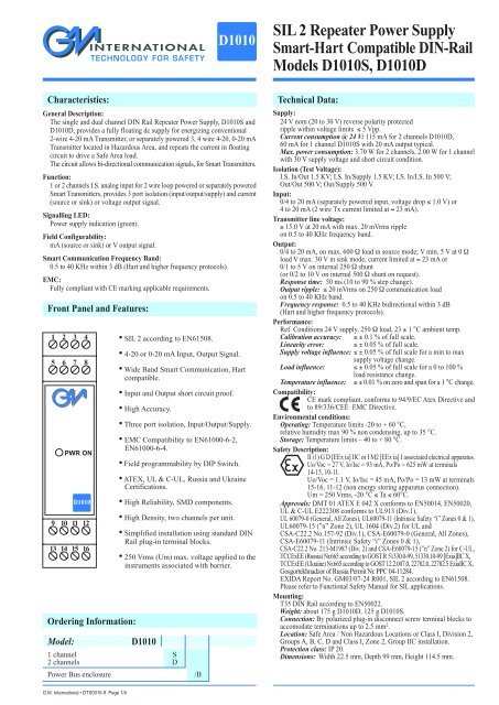
<strong>D1010</strong>SIL 2 Repeater Power SupplySmart-Hart Compatible DIN-RailModels <strong>D1010</strong>S, <strong>D1010</strong>DCharacteristics:General Description:The single and dual channel DIN Rail Repeater Power Supply, <strong>D1010</strong>S and<strong>D1010</strong>D, provides a fully floating dc supply for energizing conventional2-wire 4-20 mA Transmitter, or separately powered 3, 4 wire 4-20, 0-20 mATransmitter located in Hazardous Area, and repeats the current in floatingcircuit to drive a Safe Area load.The circuit allows bi-directional communication signals, for Smart Transmitters.Function:1 or 2 channels I.S. analog input for 2 wire loop powered or separately poweredSmart Transmitters, provides 3 port isolation (input/output/supply) and current(source or sink) or voltage output signal.Signalling LED:Power supply indication (green).Field Configurability:mA (source or sink) or V output signal.Smart Communication Frequency Band:0.5 to 40 KHz within 3 dB (Hart and higher frequency protocols).EMC:Fully compliant with CE marking applicable requirements.Front Panel and Features:1 2 3 45 6 7 8Ordering Information:Model:PWR ON<strong>D1010</strong>9 10 11 1213 14 15 16• SIL 2 according to EN61508.• 4-20 or 0-20 mA Input, Output Signal.• Wide Band Smart Communication, Hartcompatible.• Input and Output short circuit proof.• High Accuracy.• Three port isolation, Input/Output/Supply.• EMC Compatibility to EN61000-6-2,EN61000-6-4.• Field programmability by DIP Switch.• ATEX, UL & C-UL, Russia and UkraineCertifications.• High Reliability, SMD components.• High Density, two channels per unit.• Simplified installation using standard DINRail plug-in terminal blocks.• 250 Vrms (Um) max. voltage applied to theinstruments associated with barrier.<strong>D1010</strong>1 channel S2 channels DPower Bus enclosure /BTechnical Data:Supply:24 V nom (20 to 30 V) reverse polarity protectedripple within voltage limits ≤ 5 Vpp.Current consumption @ 24 V: 115 mA for 2 channels <strong>D1010</strong>D,60 mA for 1 channel <strong>D1010</strong>S with 20 mA output typical.Max. power consumption: 3.70 W for 2 channels, 2.00 W for 1 channelwith 30 V supply voltage and short circuit condition.Isolation (Test Voltage):I.S. In/Out 1.5 KV; I.S. In/Supply 1.5 KV; I.S. In/I.S. In 500 V;Out/Out 500 V; Out/Supply 500 V.Input:0/4 to 20 mA (separately powered input, voltage drop ≤ 1.0 V) or4 to 20 mA (2 wire Tx current limited at ≈ 23 mA).Transmitter line voltage:≥ 15.0 V at 20 mA with max. 20 mVrms rippleon 0.5 to 40 KHz frequency band.Output:0/4 to 20 mA, on max. 600 Ω load in source mode; V min. 5 V at 0 Ωload V max. 30 V in sink mode, current limited at ≈ 23 mA or0/1 to 5 V on internal 250 Ω shunt(or 0/2 to 10 V on internal 500 Ω shunt on request).Response time: 50 ms (10 to 90 % step change).Output ripple: ≤ 20 mVrms on 250 Ω communication loadon 0.5 to 40 KHz band.Frequency response: 0.5 to 40 KHz bidirectional within 3 dB(Hart and higher frequency protocols).Performance:Ref. Conditions 24 V supply, 250 Ω load, 23 ± 1 °C ambient temp.Calibration accuracy: ≤ ± 0.1 % of full scale.Linearity error: ≤ ± 0.05 % of full scale.Supply voltage influence: ≤ ± 0.05 % of full scale for a min to maxsupply voltage change.Load influence: ≤ ± 0.05 % of full scale for a 0 to 100 %load resistance change.Temperature influence: ≤ ± 0.01 % on zero and span for a 1 °C change.Compatibility:CE mark compliant, conforms to 94/9/EC Atex Directive andto 89/336/CEE EMC Directive.Environmental conditions:Operating: Temperature limits -20 to + 60 °C,relative humidity max 90 % non condensing, up to 35 °C.Storage: Temperature limits – 40 to + 80 °C.Safety Description:II (1) G D [EEx ia] IIC or I M2 [EEx ia] I associated electrical apparatus.Uo/Voc = 27 V, Io/Isc = 93 mA, Po/Po = 625 mW at terminals14-15, 10-11.Uo/Voc = 1.1 V, Io/Isc = 45 mA, Po/Po = 13 mW at terminals15-16, 11-12 (non energy storing apparatus connection).Um = 250 Vrms, -20 °C ≤ Ta ≤ 60°C.Approvals: DMT 01 ATEX E 042 X conforms to EN50014, EN50020,UL & C-UL E222308 conforms to UL913 (Div.1),UL 60079-0 (General, All Zones), UL60079-11 (Intrinsic Safety “i” Zones 0 & 1),UL60079-15 (”n” Zone 2), UL 1604 (Div.2) for UL andCSA-C22.2 No.157-92 (Div.1), CSA-E60079-0 (General, All Zones),CSA-E60079-11 (Intrinsic Safety “i” Zones 0 & 1),CSA-C22.2 No. 213-M1987 (Div. 2) and CSA-E60079-15 (”n” Zone 2) for C-UL,TCCExEE (Russia) Nr.665 according to GOST R 51330.0-99, 51330.10-99 [Exia]IIC X,TCCExEE (Ukraine) Nr.665 according to GOST 12.2.007.0, 22782.0, 22782.5 ExiaIIC X,Gosgortekhnadzor of Russia Permit Nr. PPC 04-11284.EXIDA Report No. GM03/07-24 R001, SIL 2 according to EN61508.Please refer to Functional Safety Manual for SIL applications.Mounting:T35 DIN Rail according to EN50022.Weight: about 175 g <strong>D1010</strong>D, 125 g <strong>D1010</strong>S.Connection: By polarized plug-in disconnect screw terminal blocks toaccomodate terminations up to 2.5 mm 2 .Location: Safe Area / Non Hazardous Locations or Class I, Division 2,Groups A, B, C, D and Class I, Zone 2, Group IIC installation.Protection class: IP 20.Dimensions: Width 22.5 mm, Depth 99 mm, Height 114.5 mm.G.M. International • DTS0016-9 Page 1/4- 24 -
Parameters Table:Safety DescriptionMaximum External ParametersGroup Co/Ca Lo/La L/R / La/RaCenelec (μF) (mH) (μH/Ω)Terminals14-15, 10-11Uo/Voc = 27 V II C 0.089 4.2 56.5Io/Isc = 93 mA II B 0.705 15.0 226.1Po/Po = 625 mW II A 2.320 33.0 452.3Terminals15-16, 11-12 Non energy storing apparatus connectionUo/Voc = 1.1 V II CIo/Isc = 45 mA II BPo/Po = 13 mW II ANOTE for USA and Canada:II C equal to Gas Groups A, B, C, D, E, F and G.II B equal to Gas Groups C, D, E, F and G.II A equal to Gas Groups D, E, F and G.Function Diagram:HAZARDOUS AREA / HAZARDOUS LOCATIONSCLASS I, DIVISION 1 and CLASS II, DIVISION 1 orCLASS I, Zone 0SAFE AREA / NON HAZARDOUS LOCATIONS orCLASS I, DIVISION 2, GROUPS A, B, C, D orCLASS I, ZONE 2, GROUP IICIn 1In 2+Externalpowered TX+Externalpowered TXHHT+?I2 Wire TXHHT+?I2 Wire TX141516101112MODEL <strong>D1010</strong>D34+–128567HHTHHTSupply 24 Vdc++RLmA+VSource I Source V++RLmA+VSource I Source VOut 1RL+mASink IOut 2RL+mASink IMODEL <strong>D1010</strong>SIn 1+Externalpowered TXHHT+?I2 Wire TX14151634+–128HHT Supply 24 Vdc++RLmA+VSource I Source VOut 1RL+mASink IG.M. International • DTS0016-9 Page 2/4- 25 -
Function Diagram:HAZARDOUS AREA / HAZARDOUS LOCATIONSCLASS I, DIVISION 1 and CLASS II, DIVISION 1 orCLASS I, Zone 0SAFE AREA / NON HAZARDOUS LOCATIONS orCLASS I, DIVISION 2, GROUPS A, B, C, D orCLASS I, ZONE 2, GROUP IICSafety DescriptionTerminals 14-15Uo/Voc = 28.1 VIo/Isc = 93 mAPo/Po = 654 mWIn 1 ?IHHT+2 Wire TX141516MODEL <strong>D1010</strong>D Duplicator34+–128HHTSupply 24 Vdc++RLmA+VSource I Source VOut 1-ARL+mASink I101112567++RLmA +VSource I Source VOut 1-BRL+mASink IConnections for Duplication of 2 wire Transmitter Input.Restriction on Specifications for 2 wire Transmitter Input.• Bi-directional communication for Smart Transmitter is provided only output channel 1.• The minimum supply voltage available for transmitters (VTx) is 14.0 V at 20 mA input.• The allowable safety parameters must be changed in: Uo/Voc = 28.1 V.Io/Isc = 93 mA.Po/Po = 654 mW.G.M. International • DTS0016-9 Page 3/4
Function Diagram:HAZARDOUS AREA / HAZARDOUS LOCATIONSCLASS I, DIVISION 1 and CLASS II, DIVISION 1 orCLASS I, Zone 0SAFE AREA / NON HAZARDOUS LOCATIONS orCLASS I, DIVISION 2, GROUPS A, B, C, D orCLASS I, ZONE 2, GROUP IICSafety DescriptionTerminals 15-16Uo/Voc = 2.2 VIo/Isc = 45 mAPo/Po = 25 mWIn 1Externalpowered TX+141516MODEL <strong>D1010</strong>D Duplicator34+–128Supply 24 Vdc++RLmA+VSource I Source VOut 1-ARL+mASink I101112567++RLmA +VSource I Source VOut 1-BRL+mASink IConnections for Duplication of Active Input Signals.Restriction on Specifications for external powered Transmitter.• The voltage drop must be changed in 2.0 V max.• The allowable safety parameters must be changed in: Uo/Voc = 2.2 V.Io/Isc = 45 mA.Po/Po = 25 mW.G.M. International • DTS0016-9 Page 4/4