Solutions for Physics 1301 Course Review (Problems 10 through 18)
Solutions for Physics 1301 Course Review (Problems 10 through 18)
Solutions for Physics 1301 Course Review (Problems 10 through 18)
- No tags were found...

You also want an ePaper? Increase the reach of your titles
YUMPU automatically turns print PDFs into web optimized ePapers that Google loves.
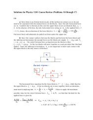
<strong>Solutions</strong> <strong>for</strong> <strong>Physics</strong> <strong>1301</strong> <strong>Course</strong> <strong>Review</strong> (<strong>Problems</strong> <strong>10</strong> <strong>through</strong> <strong>18</strong>)<strong>10</strong>)a) When the bicycle wheel comes into contact with the step, there are four <strong>for</strong>cesacting on it at that moment: its own weight, Mg ; the normal <strong>for</strong>ce upward from theground, N ; the applied <strong>for</strong>ce, F ; and the reaction <strong>for</strong>ce from the point of contact withthe step, R . If a large enough <strong>for</strong>ce is applied (and in the right place, as we shall see),the wheel will pivot about the edge of the step and lift up over it. For the minimalamount of <strong>for</strong>ce that would just make this happen, the wheel would be very nearly instatic equilibrium. It would just begin to lift off the ground, causing the normal <strong>for</strong>ce Nto drop to zero. The reaction <strong>for</strong>ce R acts at the contact point where the wheel ispivoting, so the moment arm along which it acts is zero, hence the torque it produceson the wheel is also zero.So only two of the a<strong>for</strong>ementioned <strong>for</strong>ces produce a torque on the wheel andonly one of these is unknown, so the torque equation alone will suffice to determine thevalue of F . The magnitude of a torquerτ is given byrτ = r × F r= r F sin θ ,which is equivalent to the magnitude of the <strong>for</strong>ce F times the perpendicular (or closest)distance, r sin θ , from the pivot point to the “line of action” of the <strong>for</strong>ce. Thus we find:€€
With the wheel just about to pivot around the step, the net torque is exactly zero, so theminimum applied <strong>for</strong>ce needed to lift the wheel over the step is given by⎛⎛+ Mg ⋅ 2rh − h 2 − F ⋅ (r − h ) = 0 ⇒ F = Mg ⎜⎜⎜⎜⎝⎝2rh − h 2r − h⎞⎞⎟⎟⎟⎟⎠⎠. The <strong>for</strong>m of this result appear reasonable. When there is no step ( h = 0 ) , thehorizontal <strong>for</strong>ce required to lift the wheel becomes F = 0 . Somewhat less trivially, we€ also find that it is impossible to lift the wheel, with a horizontally applied <strong>for</strong>ce, over astep with a height equal to or greater than the wheel’s radius ( F → ∞ as r → h ) .Notice that the moment of inertia, I , of the wheel does not enter into thecalculation <strong>for</strong> F . This indicates that the applied <strong>for</strong>ce required would be the same ifthe wheel were a uni<strong>for</strong>m solid disk of the same mass and radius.b) The <strong>for</strong>ce F is applied at a height h above the floor along a vertical midlineof one face of the cube (this is done so that the cube pivots up off the floor withoutturning to one side or the other).It is possible to push the cube hard enough in this way so that it will pivot <strong>for</strong>ward onits leading edge, rather than simply remaining at rest (under static friction) or slidingalong the floor (with kinetic friction). As the cube is about to pivot, the normal <strong>for</strong>cefrom the floor drops to zero. There will then be two torques acting on the cube, sincethe direction of the friction <strong>for</strong>ce is parallel to its moment arm, making the torque dueto friction zero:
torque due to weight of cube –τ W = + Mg ⋅ ( 1 2 L ) ⋅ sin 90o (the dashed arrowstorque due to applied <strong>for</strong>ce –represent the “lines ofactions” of each <strong>for</strong>ce)€τ F= − F ⋅ h ⋅ sin 90 oSo the cube is on the verge of tipping over when the net torque from these <strong>for</strong>ce is justequal to zero, or€€12⎛⎛ Mg ⎞⎞MgL − Fh = 0 ⇒ h = ⎜⎜ ⎟⎟ L .⎝⎝ 2F ⎠⎠If the <strong>for</strong>ce is applied at a point higher above the floor than this, the cube will pitch<strong>for</strong>ward and tip over, rather than slide along the floor (or possibly remain at rest if thecoefficient of static friction, µ s, is large enough).Note that as F grows very large, h becomes quite small: a very strong applied<strong>for</strong>ce delivered very low on the cube could still topple it. On the other hand, since the<strong>for</strong>ce cannot be applied any higher above the floor than h = L , we find thath =⎛⎛ Mg ⎞⎞⎜⎜ ⎟⎟ L ≤ L ⇒ Mg⎝⎝ 2F ⎠⎠2F ≤ 1 ⇒ F ≥ Mg2;this tells us that a <strong>for</strong>ce less than ½Mg applied anywhere cannot cause the cube to tipover.€c) We can examine this situation from either of two reference frames, one whichis stationary, from which to watch the truck accelerating, and the other on theaccelerating truck. Both analyses should give the same result.From the stationary viewpoint, it is the static friction between the bottom of thestack of cubes and the truck bed that causes the stack to accelerate along with thetruck. So long as the static friction can hold, f s= Ma , M being the total mass of thecubes. The stack does not accelerate in the vertical direction, so N – Mg = 0 ⇒N = Mg . We now look at the net torque about the center of mass of the stack. Theweight <strong>for</strong>ce effectively acts from this point, so the moment arm <strong>for</strong> this torque is zero,making the torque due to the weight equal to zero.
The other two torques aretorque due to friction –τ f = + 1 2 (4L ) ⋅ f s ⋅ sin 90 o = + 2 f s L = + 2MaLtorque due to normal <strong>for</strong>ce –€τ N = − x ⋅ N ⋅ sin 90 o = − N x = − Mg x€(note that <strong>for</strong> an accelerating object, the effective pointat which the normal <strong>for</strong>ce acts is not directly under thecenter of mass)The stack will not tip over as long as the net torque is zero, hence⎛⎛+ 2 MaL − Mg x = 0 ⇒ x = 2 a ⎞⎞⎜⎜ ⎟⎟ L .⎝⎝ g ⎠⎠But this will only be possible as long as the effective point from which the normal <strong>for</strong>ceacts is within the base of the stack. So the stack will not tip over provided thatx = € ⎛⎛2 a ⎞⎞⎜⎜ ⎟⎟ L ≤ 1 ⎝⎝ g ⎠⎠ 2 L ⇒ a ≤ 1 4 g . €
From the point of view of a rider in the truck bed, the stack of cubes isstationary, but it (as well as the passenger) experiences a <strong>for</strong>ce directed toward the rearof the truck, in addition to the <strong>for</strong>ce of gravity and the normal <strong>for</strong>ce. The role of staticfrictional <strong>for</strong>ce here is to oppose this rearward <strong>for</strong>ce and hold the stack of boxes inplace. Since the stack is not observed to accelerate, the equation <strong>for</strong> the horizontal<strong>for</strong>ces on the stack is f s− Ma = 0 and the vertical <strong>for</strong>ce equation is N − Mg = 0 .We can look at the torques acting about the rearward end of the base of the stack ofcubes. The static frictional <strong>for</strong>ce produces no torque because its direction of action isparallel to its moment arm. The other torques are:
The stack will not topple over as long as the net torque is zero, so1+ 2MaL + Mg x' − 1 2 MgL = 0 ⇒ x' = 2 g L − 2a Lg⎛⎛= 1 2 − 2a ⎞⎞⎜⎜ ⎟⎟ L⎝⎝ g ⎠⎠. The point of effective action <strong>for</strong> the normal <strong>for</strong>ce must remain <strong>for</strong>ward of the trailingedge of the base of the stack; thus,€⎛⎛x' =1 2 − 2a ⎞⎞⎜⎜ ⎟⎟ L ≥ 0 ⇒ 1⎝⎝ g ⎠⎠2 − 2ag ≥ 0 ⇒ a ≤ 1 4 g , since L > 0€€as we found <strong>for</strong> the stationary reference frame.f s maxbed ifWe know that the magnitude of the static friction <strong>for</strong>ce cannot exceed= µ s N = µ s Mg = 0.32 Mg , so the stack will only start to slide along the truckMa > f s max= 0.32 Mg ⇒ a > 0.32 g . Hence, the stack of cubes willtopple over be<strong>for</strong>e it would start to slide in the truck bed.€ 11) Since we will be comparing all of the <strong>for</strong>ces to the weight of the aluminum ball, wewill find it useful to find the relative masses of the copper and aluminum balls. If wecall the mass of the copper ball M and that of the aluminum ball m , we haveMm= ρ Cu V Cu= ρ Cu ⋅ 4π 3 r 3Cuρ Al V Al ρ Al ⋅ 4π 3 r = ρ 3 ⎛⎛⎛⎛ ⎞⎞ ⎛⎛Cu r ⎞⎞ 9000 kg. ⎞⎞⎜⎜ ⎟⎟ ⋅ ⎜⎜ Cu⎟⎟ =m. 33⎜⎜ ⎟⎟3ρAl ⎝⎝ Al ⎠⎠ ⎝⎝ r Al ⎠⎠ ⎜⎜ 2700 kg. ⎟⎟ ⋅ ⎛⎛ 3.0 cm. ⎞⎞⎜⎜ ⎟⎟⎝⎝ 2.5 cm. ⎠⎠⎝⎝ ⎠⎠€⎛⎛= <strong>10</strong> ⎞⎞ ⎛⎛ 6 ⎞⎞⎜⎜ ⎟⎟ ⋅ ⎜⎜ ⎟⎟⎝⎝ 3 ⎠⎠ ⎝⎝ 5⎠⎠3= 14425or 5.76 .m. 3notice that unit conversions are unnecessarywhen working with comparison ratios€
We can now analyze the <strong>for</strong>ces on each ball with the aid of the two diagramsabove: the one to the right provides geometrical in<strong>for</strong>mation which will allow us todescribe the angle θ above the horizontal made by the line connecting the centers ofthe spheres. The <strong>for</strong>ces on the copper ball arehorizontal: N ccos θ − N r= 0 ; vertical: N csin θ − Mg = 0 ,while the <strong>for</strong>ces on the aluminum ball arehorizontal: N l− N ccos θ = 0 ; vertical: N v− mg − N csin θ = 0 ,with mg being the weight of the aluminum ball. From these equations, we find thatN r= N ccos θ = N l, N csin θ = Mg , N v= mg + N csin θ .We are now able to calculate the magnitudes of all the <strong>for</strong>ces:N v = mg + N c sin θ = mg + Mg = mg + 14425mg =16925mg = 6.76 mg ;€N c = Mg144sin θ = 25 mg( 24 5.5)≈ 6.47 mg ; and€N r = N l = N c cos θ =⎛⎛ Mg ⎞⎞⎛⎛⎜⎜ ⎟⎟ cos θ = Mg cot θ = ⎜⎜144⎝⎝ sin θ ⎠⎠⎝⎝ 25 mg ⎞⎞ ⎛⎛⎟⎟ 2.5⎞⎞⎠⎠⎜⎜ ⎟⎟ ≈ 2.94 mg .⎝⎝ 24 ⎠⎠12)€ a) In this situation, due to the absence of friction, the two masses are in amarginally stable static equilibrium.We will call the downhill motion of m 1positive, which automatically makes the uphillmotion of m 2positive in turn. The net <strong>for</strong>ce on m 1acting parallel to the incline it is onis m 1g sin 40º − T = 0 , while the net <strong>for</strong>ce on m 2acting parallel to its incline isT − m 2g sin θ 2= 0 . When we solve each of these equations <strong>for</strong> the tension T in theconnecting cord and then equate the results, we find m 1g sin 40º = T = m 2g sin θ 2.Since both of the masses of the blocks are known, we can solve <strong>for</strong> the angle θ 2that isrequired in order <strong>for</strong> this static equilibrium to exist:
⎛⎛sin θ 2 = m ⎞⎞1⎜⎜ ⎟⎟ sin 40 o ≈⎝⎝ ⎠⎠m 2⎛⎛ 1.8 kg. ⎞⎞⎜⎜ ⎟⎟ ⋅ 0.643 ≈ 0.386 ⇒ θ⎝⎝ 3.0 kg.2 ≈ 22.7 o .⎠⎠€b) With the inclusion of friction, the static equilibrium of the two masses ontheir inclines becomes far more stable. In this portion of the Problem, the angle <strong>for</strong> theincline m 2rests upon is chosen to be θ 2= 32º . There are now two cases to consider<strong>for</strong> the limits of static equilibrium: one in which the mass m 1is just prevented fromsliding downhill, the other in which it is just prevented from being drawn uphill.The <strong>for</strong>ces on each mass in the case where m 1resists sliding downhill are<strong>for</strong>ces perpendicularto incline<strong>for</strong>ces parallel toinclinem 1m 2N 1 − m 1 g cos 40 o = m 1 a ⊥ = 0N 2 − m 2 g cos 32 o = m 2 a ⊥ = 0m 1 g sin 40 o − T − f s1max= m 1 a || = 0 T − m 2 g sin 32 o − f s 2max= m 2 a || = 0From the equations <strong>for</strong> the perpendicular (normal) <strong>for</strong>ces on the blocks, we obtain€€N 1= m 1g cos € 40º and N 2= m 2g cos 32º . Since € the limits of static friction on eachblock are f s1max= µ s N 1 and f s 2max= µ s N 2 , the equations <strong>for</strong> the <strong>for</strong>ces parallel toeach incline can be solved <strong>for</strong> the tension T in the cord, yieldingm 1g sin 40º − µ sm 1g cos 40º = T = m 2g sin 32º + µ sm 2g cos 32º .€If we now solve this last equation <strong>for</strong> m 2, we have⎛⎛m 2 = sin 40o − µ s cos 40 o ⎞⎞⎜⎜⎝⎝ sin 32 o + µ s cos 32 o ⎟⎟ ⋅ m 1 ≈⎠⎠⎛⎛ 0.643 − 0.38 ⋅ 0.766 ⎞⎞⎜⎜⎟⎟ ⋅1.8 kg. ≈ 0.74 kg. ,⎝⎝ 0.530 + 0.38 ⋅ 0.848 ⎠⎠€which is the smallest mass m 2may have in order to keep m 1from sliding downhill.
If the block m 2is massive enough, it will instead apply enough tension in thecord to pull block m 1uphill. The limit of static friction on m 1in this direction isfound by changing the equations <strong>for</strong> the <strong>for</strong>ces parallel to each incline tom 1 g sin 40 o − T ' + f s1max= m 1 a || = 0 and T ' − m 2 g sin 32 o + f s ↑ ↑ 2max= m 2 a || = 0 ;the equations <strong>for</strong> the normal <strong>for</strong>ces are not affected. Repeating the rest of thecalculations as we did be<strong>for</strong>e, we now have€⎛⎛€m 2 = sin 40o + µ s cos 40 o ⎞⎞⎜⎜⎝⎝ sin 32 o − µ s cos 32 o ⎟⎟ ⋅ m 1 ≈⎠⎠⎛⎛ 0.643 + 0.38 ⋅ 0.766 ⎞⎞⎜⎜⎟⎟ ⋅1.8 kg. ≈ 8.09 kg. ,⎝⎝ 0.530 − 0.38 ⋅ 0.848 ⎠⎠the greatest mass this block may have without overcoming static friction and pulling theother block along after it.€c) We continue to use the Atwood machine described in part (b), but now with amass m 2= 9.2 kg. We have seen that this will be more than sufficient mass toovercome static friction and set both blocks sliding along their inclines, with m 1moving uphill. The normal <strong>for</strong>ces acting on the blocks will still be as they were in part(b). However, with the blocks in motion, their accelerations will no longer be zero; withkinetic friction acting on the blocks, the equations <strong>for</strong> the <strong>for</strong>ces parallel to the inclinesbecomem 1 g sin 40 o − T '' + f k 1= m 1 a || andT '' − m 2 g sin 32 o + f k 2= m 2 a || ,with f k= µ kN . We now solve each equation <strong>for</strong> the new cord tension T’’ and equatethe results to find€€m 1 g sin 40 o + µ k m 1 g cos 40 o − m 1 a || = T '' = m 2 g sin 32 o − µ k m 2 g cos 32 o + m 2 a ||€€⇒ (m 1 + m 2 ) ⋅ a || = m 1 g sin 40 o + µ k m 1 g cos 40 o − m 2 g sin 32 o + µ k m 2 g cos 32 o€⎡⎡⇒ a || = m 1 (sin 40 o + µ k cos 40 o ) − m 2 (sin 32 o − µ k cos 32 o ) ⎤⎤⎢⎢⎥⎥ ⋅ g⎣⎣m 1 + m 2⎦⎦≈⎡⎡ 1.8 kg. ⋅ (0.643 + 0.26 ⋅ 0.766) − 9.2 kg. ⋅ (0.530 − 0.26 ⋅ 0.848) ⎤⎤⎢⎢⎥⎥ ⋅ (9.81 m.⎣⎣1.8 + 9.2 kg.⎦⎦ sec. 2 )≈ − 0.121 g or −1.19 m.sec. 2 .€The negative sign <strong>for</strong> this acceleration agrees with our expectation that m 1is beingpulled uphill and it is m€2that is sliding downhill.
d) With the pulley now experiencing friction with the cord connecting theblocks, the tensions in the cord on either side of the pulley are no longer equal.The equations <strong>for</strong> the <strong>for</strong>ces parallel to the inclines that we used in part (c) must bemodified to readm 1 g sin 40 o − T 1+ µ k m 1 g cos 40 o = m 1 a || ' andT 2 − m 2 g sin 32 o + µ k m 2 g cos 32 o = m 2 a || ' .€€€€Since block m 2is observed to be sliding downhill, the acceleration of bothblocks is a || ' = − 0.88 m.sec.2 . We can solve each of these <strong>for</strong>ce equations <strong>for</strong> the€tensions, since they are the only unknowns, to determine[ ]T€ 1 = m 1 ⋅ g(sin 40 o + µ k cos 40 o ) − a || '⎡⎡≈ (1.8 kg.) ⋅ (9.81 m.m.) ⋅ (0.643 + 0.26 ⋅ 0.766) − (− 0.88sec.2sec. ) ⎤⎤⎣⎣ ⎢⎢2 ⎦⎦ ⎥⎥ ≈ 16.45 N. andT 2 = m 2 ⋅ [ g(sin 32 o − µ k cos 32 o ) + a || ']⎡⎡≈ (9.2 kg.) ⋅ (9.81 m.m.) ⋅ (0.530 − 0.26 ⋅ 0.848) + (− 0.88sec.2sec. ) ⎤⎤⎣⎣ ⎢⎢2 ⎦⎦ ⎥⎥ ≈ 19.84 N.€
These unequal tensions apply a net torque to the pulley, so it will rotate. Thetorques about the center-of-mass of the pulley areτ T1= + r ⋅T 1 ⋅ sin 90 o = +T 1 r andτ T2= − r ⋅T 2 ⋅ sin 90 o = −T 2 r ,€so the net torque on the pulley is ( T 1– T 2) · r ≈ ( 16.45 – 19.84 N ) · 0.125 m.≈ −0.424 N−m. (the negative sign indicates that the rotation is clockwise, as we wouldexpect from the diagrams). €For a rigidly rotating object (all points rotate about the axis at the same angularspeed) like the pulley, the net torque is τ net= I CMα , where α is the angularacceleration. Since the edge of the pulley accelerates along with the cord, we have thesame relationship as we do <strong>for</strong> a rolling object, α = a'r . The moment of inertia of thepulley about its center of mass is thus given byI CM= τ netα= τ neta' r = r ⋅τ neta'≈0.125 m. ⋅ (−0.424 N−m.)€−0.88 m. ≈ 0.060 kg.− m. 2sec. 2€13)a) This situation can be viewed from either of two reference frames; the Problemis solved in much the same way in both cases. From the point of view of someonestanding near the conveyor belt, the graphite block falls straight down, lands with zerohorizontal velocity, and is accelerated up to the speed of the belt. Fron a viewpoint onthe belt, the block falls along a parabolic arc and lands with a horizontal speed of3 m./sec. , after which the block is brought to rest by kinetic friction. In either referenceframe, we may apply the work-kinetic energy theorem: the magnitude of the observedchange in the kinetic energy of the block is equal to the magnitude of the work done on itby kinetic friction. Since the conveyor belt is horizontal, the normal <strong>for</strong>ce on the block isN = Mg , so the kinetic frictional <strong>for</strong>ce on the block is f k= µ kN = µ kMg . The frictionacts in the opposite direction to the path along which the block slides, so the frictionalwork done on the block is = f rk • Δ x r = µ k Mg ⋅ L ⋅ cos <strong>18</strong>0 o = − µ k MgL , whereW fL is the distance the block slides along the belt. By the work-kinetic energy theorem then,we findW €f = ΔK ⇒ − µ k MgL = − 1 2 Mv 2€⇒ L =v 22µ k g ≈ (3.0 m.sec. )22 ⋅ 0.2 ⋅ 9.81 m. ≈ 2.29 m.sec. 2b) Here, there is no friction between any of the surfaces in contact, so we do notneed to be concerned with the normal <strong>for</strong>ces on the blocks. Since the only horizontal<strong>for</strong>ce € on m 1would be due to friction, in this case the upper block is not accelerated;thus, a 1= 0 . In the absence of friction, the only horizontal <strong>for</strong>ce acting on m 2is theapplied <strong>for</strong>ce F = 6 N. ; hence, the acceleration of the lower block is
a 2 =m F = 6 N. ≈ 4.62 m.2 1.3 kg. sec.2. The lower block will ultimately be pulled out fromunder the upper one.€c) Since the contact surfaces between the blocks and between the lower blockand the tabletop are horizontal, the normal <strong>for</strong>ces on the blocks are simply N 1= m 1gand N 2= ( m 1+ m 2) g . The static frictional <strong>for</strong>ce acting between the blocks is thenf s≤ µ sN 1= µ sm 1g . So the two blocks will move together as a unit provided that thislimit applies. (Since the tabletop is frictionless, N 2is not important to know andcontact with the upper block is the only source of friction.)The horizontal <strong>for</strong>ce equation <strong>for</strong> the lower block is F – f s= m 2a 2, while that<strong>for</strong> the upper block is f s= m 1a 1. If the two blocks are to stay together, theiraccelerations must match, implying thata 1 = f sm 1= a 2 = F − f sthe maximum possible value <strong>for</strong> the static frictional <strong>for</strong>cethe limit <strong>for</strong> the applied <strong>for</strong>ce is given byµ s m 1 gm 1€= F max − µ s m 1 g⇒ F max = µ s ⋅ (mm € 1 + m 2 )⋅ g2f smaxm 2. When we apply= µ s N 1 , we find that≈ 0.45 ⋅ (0.7 + 1.3 kg.)⋅ (9.81 m.sec. 2 ) ≈ 8.83 N. €Since F max> 6 N. , a horizontal applied <strong>for</strong>ce at this level still permits the blocksto stay together. Because they move as a unit, their mutual acceleration isF6 N. €a =m 1+ m=≈ 3.00 m.2 (0.7 + 1.3 kg.) sec.2 . Note that this means that the staticfrictional <strong>for</strong>ce here is f s= m 1a = ( 0.7 kg. ) ( 3.00 m./sec. 2 ) = 2.<strong>10</strong> N. , which is€
certainly less thancheck, we find thatf smax= µ s m 1 g = 0.45 ⋅ (0.7 kg.)⋅ (9.81 m.sec. ) ≈ 3.09 N. 2 As aa 2 = F − f s 6.00 − 2.<strong>10</strong> N.≈ ≈ 3.00 m.m 2 1.3 kg.sec. = a 2 .€For an applied horizontal <strong>for</strong>ce F = <strong>10</strong> N. > F max, the blocks will not movetogether and the kinetic frictional <strong>for</strong>ce f€k= µ km 1g must be used in our analysis.Upon replacing f swith f kin the horizontal <strong>for</strong>ce equations <strong>for</strong> each block, we nowhavea 1 ' =f k= µ k m 1 g = µ k g ≈ 0.32 ⋅ (9.81 m.m.) ≈ 3.14m 1sec.2sec. 2 andm 1€a 2 ' = F − f km 2≈<strong>10</strong>.0 N. − 0.32 ⋅ (0.7 kg.)⋅ (9.81 m.sec. 2 )1.3 kg.€≈<strong>10</strong>.0 − 2.20 N.1.3 kg.≈ 6.00 m.sec. 2 .The lower block will be pulled out from under the upper one, but here the upper blockwill move <strong>for</strong>ward a bit first, which was not the case in the situation we treated in part(a) above. €d) Nothing else about this system is changed if we apply the <strong>for</strong>ce to the lowerblock with a spring, instead of a cord. In order <strong>for</strong> the two blocks to continue movingtogether, the <strong>for</strong>ce applied must not exceed F max≈ 8.83 N. Hooke’s Law tells us that therestoring <strong>for</strong>ce of a spring is given by F sp= k · Δx , where Δx is the displacement of thespring from equilibrium. A maximum allowed <strong>for</strong>ce of 8.83 N. requires that the maximumpermitted displacement <strong>for</strong> this spring be (Δ x ) max = F max 8.83 N.≈ ≈ 0.123 m. Thisk 72 N./m.will set the limit on the amplitude <strong>for</strong> the pair of blocks oscillating at the end of this spring.e) There are two phases to the motion of any of the pieces of tableware: anobject is first carried along on the € rapidly accelerating tablecloth by kinetic friction,then, once the fabric has been extracted from underneath it, the same object deceleratesto rest due to the kinetic friction between the object and the tabletop.We will follow the motion of one such object, which is initially at rest on thetablecloth. If that tablecloth is now pulled with an acceleration greater than µ sg , it willovercome the static friction between the object and itself, making it possible to pull thetablecloth out from under the object. However, while the object remains in contact withthe tablecloth, it will be accelerated by kinetic friction at the rate µ kg . If we call thelength of time the object rides the tablecloth t c, then the object attains a peak speed ofv max= µ kgt cand is pulled along over the table <strong>for</strong> a distance x 1= ½ µ kg t c 2 be<strong>for</strong>e thetablecloth comes out from under it.With the object now sliding across the bare tabletop, kinetic friction will act tobring it to a stop. With a coefficient of kinetic friction µ k’ between the object and the
€tabletop, the acceleration of the object is now −µ k’g . The object will come to rest in aninterval Δt given byv f = 0 = v i + aΔt = v max + (− µ k ' g ) Δt = µ k gt c − µ k ' g Δt⎛⎛⇒ µ k gt c = µ k ' g Δt ⇒ Δt = µ ⎞⎞k⎜⎜⎝⎝ µ k'⎟⎟ t c .⎠⎠In that interval, the object will continue to slide, be<strong>for</strong>e finally stopping, by a distance€x 2 = v max ⋅ Δt + 1 2 (− µ k' g )⋅ (Δt ) 2€⎛⎛ µ= (µ k gt c ) ⋅ k⎞⎞⎜⎜⎝⎝ µ k'⎟⎟ t c⎠⎠− 1 2 µ ⎡⎡ ⎛⎛ µk' g k⎞⎞ ⎤⎤⎢⎢ ⎜⎜⎝⎝ µ k'⎟⎟ t c ⎥⎥⎣⎣ ⎠⎠ ⎦⎦2= µ k 2 g t c22 µ k '.We can also find this by applying the “velocity-squared” <strong>for</strong>mula:€v 2 f = v 2 i + 2 a (Δx ) ⇒ 0 = (µ k gt c ) 2 + 2⋅ (− µ k ' g ) ⋅ x 2 ⇒ x 2 = µ k 2 2g t c2 µ k '.We want to ensure that no object is caused to move more than 8 cm., so werequire that x€1+ x 2≤ 0.08 m.⇒1 2 µ k g t c2 + 1 2µ k2 µ k ' g t c2 = 1 2⎛⎛⎜⎜⎝⎝µ k' + µ kµ k'⎞⎞⎟⎟ ⋅ µ k g t 2 c ≤ 0.08 m.⎠⎠€⇒ t c 2 ≤2 ⋅ 0.08 m.µ k g⎛⎛ µ⋅ k' ⎞⎞⎜⎜⎝⎝ µ k' + µ⎟⎟ ≈k ⎠⎠2 ⋅ 0.08 m.0.15 ⋅ 9.81 m. ⋅sec. 2⎛⎛ 0.24 ⎞⎞⎜⎜ ⎟⎟ ≈ 0.067 sec. 2⎝⎝ 0.24 + 0.15⎠⎠⇒ t c ≤ 0.26 sec.€So the tablecloth must be pulled out quickly enough that no object rides on it <strong>for</strong> longerthan 0.26 second; this will plainly require the tablecloth to be accelerated well above€ the amount needed to overcome static friction with the objects resting on it.14) We can examine the plumb bob in the first part of this Problem using either thestationary reference frame of, say, a pedestrian on the sidewalk watching the car roundthe corner, or the accelerating reference frame of a passenger inside the car. Thisconsideration of the two differing points of view will be of use in the second part of theProblem.
In the stationary reference frame, the turning vehicle is seen undergoing acentripetal acceleration ofa C = v 2R(11 mi. ft.⋅ 5280 = hr. mi. ⋅ 1 hr.3600 sec. )227 ft.≈(16.1ft.sec. )227 ft.≈ 9.64ft.sec. 2€€or 9.64 ft.sec. 2 ⋅ 1 m.3.28 ft.≈ 2.94 m.sec. 2 .This acceleration is provided by the centripetal <strong>for</strong>ce, which is a resultant <strong>for</strong>ce in thisreference frame. In the vertical direction, the <strong>for</strong>ce equation isT cos θ − Mg = Ma V = 0 ⇒ T cos θ = Mg ⇒ T = Mgcos θIn the radial direction, we simply have T sin θ = F C, that is, the horizontal componentof the tension in the cord of the plumb line is the centripetal <strong>for</strong>ce that pulls the bob€ around the curve. From this, we find that⎛⎛T sin θ = F C ⇒ Mg ⎞⎞⎜⎜ ⎟⎟ ⋅ sin θ = Ma⎝⎝ cos θ ⎠⎠C.€⇒ tan θ = a Cg≈9.64 ft.sec. 232.2 ft.sec. 2⎛⎛⎜⎜or⎜⎜⎝⎝2.94 m.sec. 29.81 m.sec. 2⎞⎞⎟⎟⎟⎟ ≈ 0.300 ⎠⎠€⇒ θ ≈ 16.7 o from the vertical . €
From the viewpoint of a passenger in the turning car, there is no acceleration of thebob; rather it is in static equilibrium under three <strong>for</strong>ces: gravity (its own weight), thetension in the cord, and a centrifugal <strong>for</strong>ce F Cwhich pulls the bob to the outside of theturn. The radial <strong>for</strong>ce equation in this reference frame becomes T sin θ − F C= Ma r= 0 ,which then leads to the same result <strong>for</strong> θ . The Principle of Equivalence, discussed inProblem 5 , can be brought in to describe this physical situation more simply: sincethere is no acceleration of the bob observed, it is hanging “straight down” in agravitational field which happens to be tilted 16.7º with respect to a “vertical” directiondefined by the body of the car. Objects will fall toward the “outside of the turn” simplybecause this gravitational field pulls them that way. (We would also find that theacceleration due to “gravity” in this tilted field is g' = 9.81 2 + 2.94 2 ≈ <strong>10</strong>.24 m.sec. 2 . )We can now apply some of this reasoning to the second part of this Problem.From a stationary reference frame, the Earth is seen to rotate with a period of onesidereal day, which is 86,164 seconds (using € the mean solar day of 86,400 secondswill only change our results in the third decimal place), giving an angular speed <strong>for</strong> thesurface of the Earth of ω = 2π 2π rad.−5 rad.≈≈ 7.29 ⋅<strong>10</strong>T 86164 sec.sec. . So the plumb bob(and Minneapolis) are observed to travel on a circle about the Earth’s rotation axis ofradius r = R Ecos 45º (where R Eis the Earth’s equatorial radius) with a centripetalacceleration of€a C = ω 2 −5 rad.r = (7.29 ⋅<strong>10</strong>sec. )2 ⋅ (6378 km. ⋅<strong>10</strong>00 m.km. ) ⋅ 2≈ 0.0240 m.2sec. 2 .€
Now we consider the view of an observer in accelerating Minneapolis looking atthe plumb bob. The plumb line hangs “vertically” in a direction which is the vector sumof Earth’s radial gravitational field (magnitude g = 9.81 m./sec. 2 making an angle 45º tothe Equator; this takes the Earth to be a perfect sphere) and a “centrifugal” acceleration(magnitude a Cin a direction parallel to the Equator). We can apply the Law of Cosinesto the indicated vector triangle to findg' 2 = g 2 + a C 2 − 2 ⋅ g ⋅ a C ⋅ cos 45 o ≈ 9.81 2 + 0.0240 2 − 2 (9.81) (0.0240) (22 )€≈ 95.90 m.2sec. 4 ⇒ g' ≈ 9.793 m.sec. 2 .The Law of Sines then gives us€sin 45 og'= sin φa C⇒ sin φ = a Cg'⋅ sin 45 o≈0.0240 m.sec. 29.793 m.sec. 2 ⋅ (22 ) ≈ 0.00173⇒ φ ≈ 0.099 o ,€which is the deviation of the local “vertical” direction in Minneapolis from the radialdirection (the acceleration due to apparent gravity is also a little bit less than it would be<strong>for</strong> a € non-rotating Earth). To put it another way, “down” does not point exactly towardthe Earth’s center, but rather at a place about <strong>10</strong> km. closer to the South Pole along therotation axis. It is these slight deviations in the effective gravitational field of thespinning Earth that gives our planet a slightly flattened shape (called an oblatespheroid), with the polar radius being about 21 km. (0.34%) smaller than the equatorialradius.15)a) Without the action of air drag, the fall of a raindrop would simply obeyconservation of mechanical energy. If we assume that it leaves the cloud at an altitudeof 3000 meters starting nearly at rest, then the raindrop would reach the ground at aspeed given byK i+ U i= K f+ U f⇒ ½ m · 0 2 + mgh i= ½ m v f 2 + mg · 0⇒2v f= 2gh i≈ 2 ( 9.81 m./sec. 2 ) ( 3000 m. ) ≈ 59,000 m. 2 /sec. 2g is pretty nearly constantover that height (see Problem 3)⇒ v f≈ 240 m./sec. (or 540 mi./hr.) .When air resistance is taken into account, the raindrop will cease to acceleratewhen the upward drag <strong>for</strong>ce becomes equal to the downward weight <strong>for</strong>ce acting on thedrop. If we assume that the drag is proportional to cross-sectional area and to thesquare of the drop’s velocity, and that the droplet retains its spherical shape whilefalling (this last assumption is not actually realistic), then the drag <strong>for</strong>ce is modeled bythe equation F D= kAv 2 . The falling droplet will then reach a “terminal velocity” whenthe drag and weight <strong>for</strong>ces balance, given by
€€F D − mg = ma = 0 ⇒ k Av t 2 = mg ⇒ k ⋅ π r 2 ⋅ v t 2 = ρ ⋅ 4π 3 r 3 ⋅ gwe have used the area of a circle <strong>for</strong> the cross-section of the spherical drop,m = ρV <strong>for</strong> the mass of the drop, and the <strong>for</strong>mula <strong>for</strong> the volume of a sphere⇒ v t 2 = 4gρ r3k, where ρ is the density of water and k is the (assumed constant) drag coefficient.velocity thus:€We can solve this to express the radius of the droplet in terms of its terminalfaster one, we findr = 3kv t 24gρ. If we now compare the slower-falling raindrop with the⎛⎛ 3 k⎜⎜⎞⎞⎟⎟ v'2r'r = ⎝⎝ 4gρ ⎠⎠ t ⎛⎛= v t ' ⎞⎞⎜⎜⎛⎛ 3 k⎜⎜⎞⎞⎟⎟ v2 v⎟⎟⎝⎝ t ⎠⎠⎝⎝ 4gρ ⎠⎠ t2⎛⎛= 1 m. ⎞⎞⎜⎜ sec. ⎟⎟⎜⎜⎝⎝5 m. ⎟⎟⎠⎠sec.2= 1 25 .As <strong>for</strong> the <strong>for</strong>mation of the drop of water within the raincloud, if its surface areagrows at a constant rate, then the drop’s surface area will be proportional to the timespent in the € cloud; thus, S = 4πr 2 = Ct . Upon comparing the amounts of timerequired <strong>for</strong> each drop to <strong>for</strong>m, according to this model, we haveS'S=4π r'24π r 2= C t'C t⇒⎛⎛⎜⎜⎝⎝r'r⎞⎞⎟⎟ 2 =⎠⎠⎛⎛⎜⎜ 1 ⎞⎞⎟⎟ 2 =⎝⎝ 25⎠⎠1625 = t't.Thus, a raindrop which lands at 5 m./sec. is predicted to be 25 times larger in diameterthan one which lands at 1 m./sec. and requires 625 times longer to grow to that sizebe<strong>for</strong>e € falling out of its cloud. This suggests that conditions within rainclouds mustdiffer considerably to produce different sizes of raindrops.b) Hailstones will remain aloft as long as the air drag from the violent windswithin a storm cloud can overcome their weight. If we make the same assumptionsregarding them that we did <strong>for</strong> raindrops (spherical shapes, constant densities, andconstant drag coefficients regardless of size), we can use the result we obtained earlier,v 2t = 4gρ r , and apply this to the wind speed relative to an individual hailstone.3k€If we compare the wind speed required to support baseball-sized hail to thatneeded to pea-sized hail aloft, we can estimate thatv' t2v t2=⎛⎛ 4gρ ⎞⎞⎜⎜⎜⎜⎟⎟⎝⎝ 3k ⎠⎠⎛⎛ 4gρ ⎞⎞⎜⎜⎜⎜⎟⎟⎝⎝ 3k ⎠⎠⎟⎟ r'= r'⎟⎟ r r= 2r'2r=7.5 cm.0.75 cm. = <strong>10</strong> ⇒ v t 'v t= <strong>10</strong> ≈ 3.2 .€So the turbulent wind speeds in a storm cloud need to be about three times faster tosupport the largest sorts of hailstones than are required <strong>for</strong> the more typical sizes ofhail. (Winds within the most violent cumulonimbus clouds can exceed 120 mph.)
€16)a)rThe three horizontal <strong>for</strong>ces acting on the car are the applied <strong>for</strong>cerfrom theengine, F A , the kinetic frictional <strong>for</strong>ce between the tires and the road, f k , and thedrag <strong>for</strong>ce from the air,€rF D . Since the vehicle is on a level road here, the normal <strong>for</strong>ceon it from the road surface is N = Mg , so the kinetic frictional <strong>for</strong>ce is fk= µ kMg .€€€With the car traveling at constant speed, the net horizontal <strong>for</strong>ce on the car isrF netx = F rA + f rk + F rD = 0 ⇒ F netx = F A − f k − F D = 0 . The net power appliedto the car will then also be zero:P net = F rnetx ⋅ v r =rF A ⋅ r v + rf k ⋅ r v += F A v − f k v − F D v = 0 .rF D ⋅ r v =rF A v cos 0 o+ rf k v cos <strong>18</strong>0 o + rF D v cos <strong>18</strong>0 oWe are told that the power being provided by the engine is P A= F Av = 95,000 W .€ At a speed of v = 65 mi. ⋅ 1609 m. 1 hr.⋅ ≈ 29.05 m.hr. mi. 3600 sec. sec. , the portion of this powerthat is being used to overcome air drag is€P D = F D v = F A v − f k v = P A − µ k Mgv€= 95,000 W − 0.025 ⋅ (900 kg.) (9.81 m. m.) (29.05sec.2 sec. )≈ 95,000 − 64<strong>10</strong> W ≈ 88,600 W .€To maintain the car at this speed,used € to overcome air drag.88,600 W95,000 W ≈ 0.933 of the engine’s power is being€b) If the drag <strong>for</strong>ce is proportional to the square of the vehicle’s speed, then atF € D'80 mph, the drag is = v'22⎛⎛ 80 mph⎞⎞F D v 2 = ⎜⎜ ⎟⎟ ≈ 1.515 times stronger than it is at⎝⎝ 65 mph⎠⎠65 mph. The power necessary to overcome air drag at this higher speed, however, isP D '= F D 'v'P DF Dv = ⎛⎛ v'2 ⎞⎞⎜⎜€⎝⎝ v 2 ⎟⎟ ⋅ v'3⎠⎠ v = ⎛⎛ 80 mph⎞⎞⎜⎜ ⎟⎟ ≈ 1.864 times greater than at 65 mph. This⎝⎝ 65 mph⎠⎠gives us P D’ ≈ 1.864 P D≈ 1.864 · 88,600 W ≈ 165,200 W . The total power the enginemust now supply is P A’ = P D’ + P f≈ 165,200 + 64<strong>10</strong> W ≈ 171,600 W ( 230 hp ) .
c) With the car now moving up an incline, the normal <strong>for</strong>ce from the roadsurface becomes N’ = Mg cos θ , making the kinetic frictional <strong>for</strong>ce f k’ = µ kMg cos θ .In addition to the <strong>for</strong>ces already described, the weight <strong>for</strong>ce on the vehicle now also hasa component parallel to the incline, W ||= Mg sin θ .The net <strong>for</strong>ce on the car is nowrF net|| = F rA +F rD + f rk ' +rW ||= 0 , so the netpower becomes P net= F Av − F Dv − ( µ kMg cos θ ) v − ( Mg sin θ ) v = 0 . Since thecar is on a 12% grade, tan θ = 0.12 ⇒ sin θ ≈ 0.1191 , cos θ ≈ 0.9929 . We haveseen that the power exerted by air drag is P€D≈ 88,600 W at 29.05 m./sec. (65 mph)⎛⎛and that it is proportional to v 3 , so we can write P D = 88,600 ⎜⎜ v ⎞⎞⎟⎟ 3 W . The⎝⎝ 29.05⎠⎠power which must be delivered by the engine in order <strong>for</strong> the vehicle to maintain aspeed v on the 12% upward incline is thenP A= F A v = P D + (µ k Mg cos θ ) v + (Mg € sin θ ) v€⎛⎛≈ 88,600 ⎜⎜ v ⎞⎞⎟⎟ 3 + (0.025) (900 kg.) (9.81 m.m.) (0.9929) v + (900 kg.) (9.81⎝⎝ 29.05⎠⎠) (0.1191) vsec. 2 sec. 2≈ 3.614 v 3 + 219.2 v + <strong>10</strong>52 v ≈ 3.614 v 3 + 1271v .€We are going to keep the power from the engine at the same level it had inpart (b) above, so we need to solve <strong>for</strong> v the equation 3.614 v 3 + 1271 v = 171,600 .€ It is not very convenient to solve this last equation directly (we can, of course, usegraphing software, as will be discussed below), but we don’t need to resort to trial-anderrorcompletely either. We know that this amount of power on level ground allows thecar to travel at 80 mph ( ≈ 35.8 m./sec. ), so we might expect that on a 12% climb, thecar might move, say, <strong>10</strong>% or so slower. Let’s make a first guess that the solution isv = 32 m./sec. Since the cubic term in the equation, 3.614 v 3 , changes much morerapidly than the linear term, 1271v , we’ll simply set this term to 1271 · 32 <strong>for</strong> thepresent and solve the following <strong>for</strong> v :3.614 v 3 + 1271⋅ 32 = 3.614 v 3 + 40670 = 171,600 ⇒ 3.614 v 3 = 130,900 ⇒ v 3 ≈ 36,200 ⇒ v ≈ 33.1sec.m. ,€which is pretty close to our initial guess. If we adjust the linear term to accommodatethis new value, we find€
3.614 v 3 + 1271⋅ 33.1 = 3.614 v 3 + 42070 = 171,600 ⇒ v ≈ 33.0 m.sec.. €Our solution has stabilized to one decimal place, so we may stop here. A more precisesolution, using graphing software to find the x-intercepts <strong>for</strong> the function3.614 v 3 + 1271 v − 171,600 , gives us v ≈ 32.98 m./sec. , so our result is acceptable.As a check, we can calculate the individual power terms:power exerted against drag: P A≈ 3.614 · 33.0 3 ≈ 129,900 Wpower exerted against friction: P f≈ 219.2 · 33.0 ≈ 7230 Wpower exerted against gravity: P W≈ <strong>10</strong>52 · 33.0 ≈ 34,700 Wtotal power to be delivered by engine: 171,800 W ,agreeing with the intended total value to about 0.12% .d) Without the applied <strong>for</strong>ce from the engine, and assuming that there is nointernal friction in the drive train of the car (a bit unrealistic), the net <strong>for</strong>ce on thevehicle acting parallel to the downward incline isrF net|| ' =rW || +F rD + f rk ' = 0 ⇒ F net|| ' = W || − F D − f k ' = 0 ,€making the net power P net= ( Mg sin θ ) v − F Dv − ( µ kMg cos θ ) v = 0 .€Each of these terms has the same value as it did in part (c) above, giving us<strong>10</strong>52 v − 3.614 v 3 − 219.2 v ≈ 832.3v − 3.614 v 3 = 0 ,which is much easier to solve <strong>for</strong> v than the power equation we found in the previouspart. We can factor this as v ⋅ (832.3 − 3.614 v 2 ) = 0 , so either v = 0 (theuninteresting solution, since the power terms are of course all zero when the car isparked) or 832.3 − 3.614 v 2 = 0 ⇒ v 2 ≈ 230.3 ⇒ v ≈ 15.2 m./sec. (34 mph) .In a real vehicle, internal friction would make the downhill coasting speed somewhatlower than this. €€17) With the puck moving on a frictionless surface, it is possible to arrange a steadystatesituation (not a static, but rather a dynamic equilibrium) in which the puck travelson a circle at a constant tangential speed v . The centripetal <strong>for</strong>ce keeping the puckmoving on its circle is provided by the physical <strong>for</strong>ce of tension in the cord connecting itto the hanging weight. If we set things up so that the suspended mass remains at rest,then the vertical <strong>for</strong>ce equation <strong>for</strong> this mass is T – Mg = Ma V= 0 ⇒ T = Mg . Thecentripetal <strong>for</strong>ce on the puck is thusF C = mv 2R = T = Mg .€
The tangential speed which the puck should be given in order to maintain thisequilibrium is then given byv 2= M m⋅ gR ≈1.3 kg.0.3 kg.m.m.2(9.81 ) (0.45 m.) ≈ 19.1 ⇒ v ≈ 4.37 m.sec.2sec. 2 sec..€€If we now introduce a frictional <strong>for</strong>ce by considering the motion of the puck on areal air table, the kinetic friction produces a torque on the revolving puck, causing achange in its angular momentum. (Note: the friction will also dissipate the mechanicalenergy of the system, causing the hanging mass to descend and the puck to movetoward the center by spiraling inward; we are not in a position in this course, however,to analyze the changes in a system where the circulating object changes distance fromthe axis of rotation – this requires somewhat more advanced mechanics.) If the rate ofchange is not too rapid, the puck’s velocity, and hence the direction of the kineticfrictional <strong>for</strong>ce, will be very nearly perpendicular to the cord. The angular momentumat the moment described in the Problem is thenrL 0 = r 0 × p r0 ⇒ L 0 ≈ R 0 ⋅ mv 0 ⋅ sin 90 o ⎛⎛ M= R 0 ⋅ m ⋅m ⋅ gR ⎞⎞⎜⎜0⎟⎟ 1/ 2 =⎝⎝ ⎠⎠and the frictional torque isrτ f = r × f rk ⇒ τ f ≈ R ⋅ µ k N ⋅ sin 90 o = µ k mg R .( gmM ) 1/ 2 3 / 2⋅ R 0Since this torque acts in the opposite direction to the angular momentum, we can write€−µ k mg R ≈ τ f = dLdt≈d dtgmM ( ) 1/ 2 ⋅ R 3 / 2[ ] = 3 2 gmM ( ) 1/ 2 ⋅ R 1/ 2 dRdt€
⇒dRdt≈−µ k mg R32 gmM( ) 1/ 2 = − 2R 1/ 2 3 µ k g m ⎝⎝ M1/ 2⎛⎛ ⎞⎞⎜⎜ ⎟⎟ R 1/ 2 .14 24 ⎠⎠43AA is a constant whichwe shall refer to belowAt the moment described in the Problem, we find€⎛⎛⎜⎜⎝⎝dRdt⎞⎞⎟⎟⎠⎠0≈ − 2 3 µ k( g m M ) 1/ 2 1/R 2 0 ≈ − 2 3≈ − 0.00054 m.sec.or⎛⎛ m. 0.3 kg. ⎞⎞(0.0008) ⎜⎜ 9.81 ⋅⎝⎝ sec. 2⎟⎟1.3 kg. ⎠⎠− 0.54 mm.sec.1/ 2(0.45 m.) 1/ 2€Since the puck is getting closer to the hole in the table and is attached to the hangingmass by the same cord, that mass is descending at this rate as well. The spiraling-in ofthe puck € is quite slow, so we can reasonably apply the tangential speed relationship wefound earlier, v 2 = M m⋅ gR . We see from this that the tangential speed becomessmaller as the radius at which the puck travels shrinks. So the puck is slowing down asit spirals in toward the hole.€ We can examine this in somewhat more detail by using the differential equationdRwe have determined, = − AR 1/ 2 , with A > 0 . By rearranging this equation (indtwhat is called a “separation of variables”), we can then integrate both sides to solve <strong>for</strong>the radius of the (approximate) circle on which the puck is moving as a function of time:dRdt€= − AR 1/ 2 ⇒A being the constantshown abovedR∫ = − A ∫ dt ⇒ 11 2 R1/ 2 = − At + C ;R 1/ 2€since, at t = 0 , R(0) = R 0, we have 2R 01/2= −A · 0 + C ⇒ C = 2R 01/2, and henceR 1/ 2 = − 1 ⎡⎡22 3 µ ⎛⎛k g m ⎞⎞⎢⎢ ⎜⎜⎝⎝ M ⎟⎟⎣⎣ ⎢⎢ ⎠⎠1/ 2⎤⎤⎥⎥⎦⎦ ⎥⎥ ⋅ t + 1 ⎧⎧2 ⋅ 2R 1/ 0 2 ⎪⎪ ⎡⎡1/⇒ R(t ) = R 2 0 − 1 3 µ ⎛⎛k ⎜⎜ g m ⎞⎞⎨⎨ ⎢⎢ ⎟⎟⎩⎩ ⎪⎪ ⎣⎣ ⎢⎢ ⎝⎝ M ⎠⎠1/ 2⎤⎤ ⎫⎫⎥⎥⎦⎦ ⎥⎥ t ⎪⎪⎬⎬⎭⎭ ⎪⎪2and, using the tangential speed equation above, we obtain€v(t ) = g M m ⋅ R1/ 2 = g M ⎧⎧m ⋅ ⎪⎪ ⎡⎡− 1 3 µ ⎛⎛k ⎜⎜ g m ⎞⎞⎨⎨ ⎢⎢ ⎟⎟⎩⎩ ⎪⎪ ⎣⎣ ⎢⎢ ⎝⎝ M ⎠⎠1/ 2⎤⎤ ⎫⎫⎥⎥⎦⎦ ⎥⎥ ⋅ t + R 1/ 0 2 ⎪⎪⎬⎬⎭⎭ ⎪⎪€= g M ⎡⎡m R 1/02 − 1 3 µ ⎛⎛k g m ⎞⎞⎢⎢ ⎜⎜ ⎟⎟⎣⎣ ⎢⎢ ⎝⎝ M ⎠⎠3 / 2⎤⎤⎥⎥⎦⎦ ⎥⎥ t. €
We can now estimate the time T at which the radius of the circle the puck moves alongdrops to zero⎡⎡1/R 2 0 − 1 3 µ ⎛⎛k g m ⎞⎞⎢⎢ ⎜⎜ ⎟⎟⎣⎣ ⎢⎢ ⎝⎝ M ⎠⎠1/ 2⎤⎤⎥⎥⎦⎦ ⎥⎥ T = 0 ⇒ T = R1/ 2013 µ k g m M( ) 1/ 2 = 3⎛⎛ M R ⎞⎞⎜⎜ 0⎟⎟µ k ⎝⎝ mg ⎠⎠1/ 2€≈⎛⎛⎞⎞3 ⎜⎜ 1.3 kg. ⋅ 0.45 m. ⎟⎟0.0008 ⎜⎜ 0.3 kg. ⋅ 9.81 m. ⎟⎟⎝⎝sec. 2 ⎠⎠1/ 2≈ 1700 sec. ;we find that the tangential speed also becomes zero at this time ( v ( T ) = 0 ) . Relatedphysical quantities, such as the angular momentum of the puck, L ( t ) = ( gmM ) 1/2 R 3/2 ,the frictional torque acting € on it, τ ( t ) = −µ kmgR , and the rotational kinetic energy ofthe puck, K rot (t ) = 1 2 Iω 2 = 1 2 (mR 2 ⎛⎛) ⎜⎜ v ⎞⎞⎟⎟ 2 = 1 ⎝⎝ R⎠⎠2 m v 2 = 1 2 m ⋅ ⎛⎛ M ⎞⎞⎜⎜ ⎟⎟ gR = 1⎝⎝ m ⎠⎠ 2 MgR , all fallsmoothly to zero as the time approaches T . (It should be said that the time T is only anestimate since the approximation that the puck is traveling on diminishing circles breaksdown when the radius becomes less than several centimeters.)€<strong>18</strong>) For the object rolling on the surface of the globe, there are two <strong>for</strong>ces acting upon it(we can neglect rolling friction): the normal <strong>for</strong>ce, N , and the weight <strong>for</strong>ce, mg . Whatwill be of interest to us are the components of these <strong>for</strong>ces in the radial direction, astheir resultant provides the centripetal <strong>for</strong>ce holding the object on its circular motion asit travels down a meridian of the globe’s surface. If we call the radial direction towardthe center of the globe positive and θ is the “polar angle” measured downward fromthe top of the sphere, the <strong>for</strong>ce in the inward radial direction ismg cos θ − N = F C = mv 2, with R being the radius of the globe.R€
By itself, the <strong>for</strong>ce equation is not of enough help to us: we also need to knowsomething about the speed of the object as it rolls. It is not convenient to determinethis from analyzing the <strong>for</strong>ces, since the acceleration is not constant (or easilyintegrated). Since we are treating friction as negligible, mechanical energy is conserved;if we compare this total energy at the top of the sphere ( θ = 0 , which we take to be theNorth Pole of the globe) and at polar angle θ , we findK i+ U i= 0 + mgR = K f+ U f= ( K lin+ K rot) + mgh .The linear kinetic energy of the rolling object is K lin= ½ mv 2 , while its rotationalkinetic energy is K rot= ½ I ω 2 = ½ ( Cmr 2 ) · ( v/r ) 2 = ½ Cmv 2 , where C is theobject’s coefficient of rotational inertia, and rolling requires that ω = v/r , r being theradius of the object. With h = R cos θ , our conservation of energy equation becomesmgR = 1 2 mv 2 + 1 2 C mv 2 + mgR cos θ ⇒ v 2 =2 ⋅ gR (1 − cos θ )1 + C.€We now return to the <strong>for</strong>ce equation. The rolling object will remain on thesurface of the globe as long as N > 0 ; it breaks contact with the surface at the pointwhere the normal <strong>for</strong>ce drops to zero. At that position, we can say thatmg cos θ − 0 = mv 2R⇒ g cos θ =⎡⎡ 2 ⋅ gR (1 − cos θ ) ⎤⎤⎣⎣ ⎢⎢ 1 + C ⎦⎦ ⎥⎥R⇒ cos θ =2 (1 − cos θ )1 + C€⇒ (1 + C ) cos θ = 2 − 2 cos θ ⇒ cos θ =23 + C .For a marble of uni<strong>for</strong>m density, which is a solid sphere, C = 2/5 , so the marble leaves2 2the surface € of the globe at cos θ =3 + 2 =( 17 = <strong>10</strong>5 5 ) 17 ⇒ θ ≈ 54.0o ; since thelatitude on the globe is λ = 90º − θ , the marble flies off the globe at λ ≈ 36.0º .The finger ring behaves nearly like an idealized hoop with C ≈ 1 , so it leaves the globe’s2surface where cos € θ =3 + 1 = 2 4 = 1 2 ⇒ θ = 60.0o ⇒ λ = 30.0 o .€By contrast, a sliding block will have no rotational kinetic energy, so C = 0 ,2giving cos θ =€ 3 + 0 = 2 3 ⇒ θ = 48.2o ⇒ λ = 41.8 o . Since this mass does notrotate, it builds up speed on the globe’s surface faster and so overcomes earlier theability of gravity to hold it along the curved surface.-- G.Ruffaoriginal notes developed during 2007-09revised: August 20<strong>10</strong>