LSD FF Hydraulic Side Cover Instructions - Baker Drivetrain
LSD FF Hydraulic Side Cover Instructions - Baker Drivetrain
LSD FF Hydraulic Side Cover Instructions - Baker Drivetrain

Create successful ePaper yourself
Turn your PDF publications into a flip-book with our unique Google optimized e-Paper software.
left-side-drivehydraulic side coverinstallation manualrear feed and front feed modelsrear feedfront feedfor baker OD6, dd5, dd6, and stock H-D 5-speedsv3-021307 | DD5, DD6, and Stock H-D <strong>Instructions</strong> | of 9
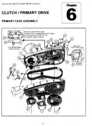
dd5, dd6, and stock H-D 5-speeds176r/6f3248985999LABEL QTY P/n description1 1 37089-84 Clutch Actuator Rod2 2 66855 O-Ring, <strong>Hydraulic</strong> Piston3 1 124-56L BAKER <strong>Hydraulic</strong> Piston, <strong>LSD</strong>4 1 130-56BS BAKER <strong>LSD</strong> Dipstick5 1 66825 O-Ring, Dipstick6r 1 452-DP-56 BAKER <strong>Hydraulic</strong> <strong>Side</strong> <strong>Cover</strong>, Rear Feed, <strong>LSD</strong>6f 1 451-DP-56 BAKER <strong>Hydraulic</strong> <strong>Side</strong> <strong>Cover</strong>, Front Feed, <strong>LSD</strong>7 1 94-5404 Bleeder Release Valve8 2 2AL2.250-12SL 1/4-20 x 2.25 12pt. ARP Bolt, Stainless9 4 2AL1.250-12SL 1/4-20 x 1.25 12pt. ARP Bolt, Stainlessv3-021307 | DD5, DD6, and Stock H-D <strong>Instructions</strong> | of 9
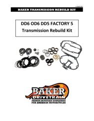
OD6 (Overdrive 6-speed)176r/6f3248985910LABEL10QTY P/n description1 1 37089-84L Clutch Actuator Rod2 2 66855 O-Ring, <strong>Hydraulic</strong> Piston3 1 124-56L BAKER <strong>Hydraulic</strong> Piston, <strong>LSD</strong>4 1 130-56BS BAKER <strong>LSD</strong> Dipstick5 1 66825 O-Ring, Dipstick6r 1 452-DP-56 BAKER <strong>Hydraulic</strong> <strong>Side</strong> <strong>Cover</strong>, Rear Feed, <strong>LSD</strong>6f 1 451-DP-56 BAKER <strong>Hydraulic</strong> <strong>Side</strong> <strong>Cover</strong>, Front Feed, <strong>LSD</strong>7 1 94-5404 Bleeder Release Valve8 2 2AL2.250-12SL 1/4-20 x 2.25 12pt. ARP Bolt, Stainless9 2 2AL1.000-3SL 1/4-20 x 1.00 12pt. ARP Bolt, Stainless10 2 2AL1.250-12SL 1/4-20 x 1.25 12pt. ARP Bolt, Stainlessv3-021307 | DD5, DD6, and Stock H-D <strong>Instructions</strong> | of 9
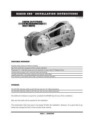
aker <strong>LSD</strong> HYDraulic side cover, <strong>Instructions</strong>Features:The new line of BAKER <strong>Hydraulic</strong> <strong>Side</strong> <strong>Cover</strong>s follows the very exciting launch of the Torquebox line of Transmissionsearly in 2006 down the BAKER <strong>Drivetrain</strong> Function Formed Design path. Utilizing our years of technical and highperformance functional design experience, matched with our keen eye for race inspired aesthetic design; we wrappedthe outer billet aircraft aluminum skin of the parts around the technical components within the package. In straightEnglish, there is no extra material or bullshit other than the absolutely necessary parts to make it function preciselyand look damn good doing it.Fitment:The BAKER <strong>Hydraulic</strong> <strong>Side</strong> <strong>Cover</strong>s will fit the following models right out of the box:91-99 EVO Softails, Dyna & FXR’s2000-2006 Twin Cam Softails1998-2006 BAKER OD6, DD6 & DD5 Models2000-2005 DynaThe BAKER <strong>Hydraulic</strong> <strong>Side</strong> <strong>Cover</strong>s will fit the following models with the additional purchase of a BAKER FL EngineOil Spout and Dipstick. RELEASE DATE OF FALL 06: (This is due to interference between the Bleeder Valve and<strong>Hydraulic</strong> Banjo with the existing stock oil spout and cover assembly)91-99 EVO FL & Touring Models2000-2006 Twin Cam FL & Touring ModelsDesigned for use with a 11/16” Bore <strong>Hydraulic</strong> Clutch Lever,AN-3 brake line, 10mm banjo fitting and a 3/8”-24Banjo Bolt.Necessary Knowledge, Parts and ResourcesIt is strongly recommended by BAKER <strong>Drivetrain</strong> when performing this task or any other task related to the<strong>Drivetrain</strong> components on your motorcycle, that you have a correct and current Factory Service manual onhand for your specific model of motorcycle.You normal set of hand tools are all that you need for installation, no specialty tools are required.Transmission Fluid, We recommend Redline Heavy Duty Shockproof Gear Oil (BAKER pn: LRL-56)<strong>Hydraulic</strong> Fluid: We recommend H-D DOT 5 Brake Fluid (H-D pn: 99902-77)v3-021307 | DD5, DD6, and Stock H-D <strong>Instructions</strong> | of 9
Disassembly:1) Remove and set aside any exhaust, saddlebags, brackets, passenger foot pegs or any other part in direct lineof removing the current side cover on your motorcycle.2) Drain the oil out of the transmission. If unsure about the location of the drain plug seek reference in the FactoryService manual.3) Loosen all 6 of the socket head cap screws holding the side cover onto the bearing door on the right sideof your motorcycle. Then actuate the clutch at the handlebar to break the seal of the side cover to thetransmission case and the case dowel pins.4) Unscrew the side cover from the clutch cable and pull out the actuator rod and washer assembly from themainshaft and set aside. Unbolt the clutch cable from the hand lever and set aside. Remove clutch lever fromhandlebars and set aside. Also pull the 2 split dowel pins out of the bearing door with a set of pliers.5) Before beginning to install your new BAKER <strong>LSD</strong> <strong>Hydraulic</strong> <strong>Side</strong> <strong>Cover</strong>, make sure to inspect the bearing doorgasket surface that it is free of any debris or old gasket material in order to help ensure a good seal with thenew gasket and to prevent leaks in the future.6) Remove the derby cover from your outer primary and loosen the clutch adjustment nut in the center and backthe nut off to the end of the rod.Assembly:1) Using a dead blow hammer, gently tap the provided split pins into the bearing door.2) Put the provided BAKER side cover gasket in place on the bearing door using the split pins to aid as locatersand to hold the gasket in place while placing the BAKER <strong>LSD</strong> <strong>Hydraulic</strong> <strong>Side</strong> <strong>Cover</strong> on the bearing door.3) Place the provided clutch actuator rod assembly into the hole in the end of the mainshaft in preparation for sidecover installation.4) Remove the hydraulic piston from the side cover. The best way is to use the light touch of an air blow gun inthe hydraulic feed port. It should be noted that you should have the side cover back side down on a couple oftowels on the work bench when doing this as the piston will shoot out. When you have the piston out, give it abath of H-D DOT 5 Brake Fluid making sure to fully coat the o-rings in the brake fluid.FAILURE TO TAKE PRECAUTIONS TO NOT DAMAGE THE PISTON WILL RESULT IN HYDRAULIC BOREDAMAGE AND SUBSEQUENT PART FAILURE.5) Double check that the inside of the hydraulic bore is free of debris and dirt. Also check the entire inside surfacev3-021307 | DD5, DD6, and Stock H-D <strong>Instructions</strong> | of 9
of the side cover to eliminate introducing dirt or packing material into your transmission. With the inside of thepart checked and determined to be clean, coat the inside walls of the hydraulic bore with the same H-D DOT 5Brake Fluid used to lubricate the o-rings.THESE EXTRA STEPS OF LUBRICATION MAKE A VERY DRAMATIC DI<strong>FF</strong>ERENCE IN THE WEAR LIFEOF THE SEALING O-RINGS IN YOUR BAKER <strong>LSD</strong> HYDRAULIC SIDE COVER AND ARE NECESSARYFOR CORRECT PART FUNCTION.6) Using a gentle touch, slide the piston back in the side cover until it bottoms out. Take care to not force thepiston into place, in such a way that o-ring damage could occur on the edge or opening of the <strong>Hydraulic</strong> Bore.7) With the piston, lubricated and placed into the side cover, put the side cover in place over the locating split pinson the bearing door. Using a rubber mallet, gently tap the BAKER <strong>LSD</strong> <strong>Hydraulic</strong> <strong>Cover</strong> into place flush againstthe gasket against the bearing door.8) Using the provided ARP 12 pt stainless steel fasteners, snug the side cover down to the bearing door. Referto the attached exploded view parts diagram for the locations of the various length bolts. Once all of the boltsare snugged up and the side cover is evenly pressed against the gasket torque the bolts to 110 in-lbs. See163 452v3-021307 | DD5, DD6, and Stock H-D <strong>Instructions</strong> | of 9
attached bolt torque sequence diagram.9) Now bolt the <strong>Hydraulic</strong> Clutch lever of your choice to the handlebars. The BAKER <strong>LSD</strong> <strong>Hydraulic</strong> <strong>Side</strong> <strong>Cover</strong>is designed to work with the stock clutch master cylinder bore size of 11/16”. Attach and route the AN-3 brakeline of your choice while using a 3/8”-24 threaded banjo bolt at the side cover. The Rear Feed model BAKER<strong>LSD</strong> <strong>Hydraulic</strong> <strong>Side</strong> <strong>Cover</strong> is designed for use with a 35˚ 10mm, AN-3 fitting, enabling the hydraulic line to berouted forward on the motorcycle under the side cover. The Front Feed model BAKER <strong>LSD</strong> <strong>Hydraulic</strong> <strong>Side</strong><strong>Cover</strong> is designed to allow use of any neck style 10mm banjo fitting, including straight, 35 o and 90 o .The fittingangle and Banjo bolt at the Clutch lever are dependent on the brand and model of clutch lever that you decidedto use. That information needs to come from the manufacturer of the clutch lever.TAKE THE NECESSARY TIME AND PROPER PRECAUTIONS TO ROUTE THE HYDRAULIC LINE AWAYFROM MOVING PARTS AND ANY EXHAUST PIPES THAT COULD DAMAGE THE LINE IN ANY WAY.FAILURE TO DO SO COULD RESULT IN PART FAILURE, PERSONAL INJURY OR DEATH.Bleeding The <strong>Hydraulic</strong> <strong>Side</strong> <strong>Cover</strong> AssemblyBAKER <strong>Drivetrain</strong> makes the strong recommendation that a power bleeder system beutilized, whether that it is a hand operated pump or pneumatic, to bleed the hydraulicclutch system on your motorcycle. It is the most effective and only surefire wayto ensure that all the air bubbles are purged from the system. If you do not owna power bleeder, the following set of instructions will enable you to bleed yourclutch system. Great care needs to be paid to the following steps to ensure aproperly bled and functioning system to ensure your safety as a rider.1) Before you can bleed the <strong>Hydraulic</strong> Clutch system you need to adjust the free play and rod length at the clutch.Using an allen wrench, run the adjuster bolt (center of the clutch) inboard until it can be felt to bottom the pistonout in the side cover. You will also know that you have hit the bottom point as the clutch will begin the move. Atthe point where it is fully bottomed out, back the bolt off ½ to 1 full turn. The closer to the 1 full turn point thatyou adjust it too, the more reserve you will have in the lever before the motorcycle begins to move, with thefull engagement of the clutch being proportionally closer to the end of the sweep of the lever. This amount canbe adjusted to rider comfort and riding style. Tighten the jam nut to 120 in-lbs while holding the adjuster screwv3-021307 | DD5, DD6, and Stock H-D <strong>Instructions</strong> | of 9
from rotating.2) Place a clear tube over the bleeder valve on the side cover and run it into a clean container.3) Stand the motorcycle upright so that the master cylinder on the clutch lever is level. Remover the lid andgasket.4) Add new DOT 5 Silicone <strong>Hydraulic</strong> Fluid to the master cylinder reservoir under to the fluid level is at or belowthe full line. DO NOT OVERFILL THE MASTER CYLINDER.5) Squeeze the lever 5-10 times. Open the bleeder valve on the side cover and clutch fluid should flow throughthe tubing. If not, keep pumping the lever as it may take a few minutes for the fluid to make it all of the waythrough the line and cover. Once fluid begins to flow through the clear tube, close the bleeder valve. It may benecessary to add more fluid during this time even before any fluid begins to flow out of the clear tubing.6) Squeeze the clutch lever and hold it against the handlebar to build up hydraulic pressure. Open the bleedervalve on the side cover about ½ turn. Clutch fluid will flow through the clear tubing. Close the bleeder whenthe clutch lever has traveled about 50-75% of its full travel. Wait for the clutch lever to return to its releasedposition. Repeat step 6 as necessary until all air bubbles have been forced out of the system and there is nobubbles in the fluid within the clear tubing.7) When the system has been fully bled and the clutch lever no longer feels mushy, fully tighten the bleeder valveon the side cover to 80 in-lbs. It may be necessary to fill the fluid in the reservoir to the full line at this time.DO NOT OVERFILL THE MASTER CYLINDER.8) Place the cover back on the master cylinder and tighten down according to the control manufacturer’sspecifications. Check to make sure that the clutch line is tight at the clutch lever and the side cover at this time.9) Replace the derby cover on the primary, referring to the factory service manual for the proper tighteningsequence.Filling the Transmission with Fluid1) Remove the BAKER <strong>LSD</strong> Dipstick from the side cover with a 5/16 hex key. Using a measuring cup and funnel,fill the transmission with 20-24oz’s of Redline Heavy Duty Shockproof Gear Oil.THE BAKER <strong>LSD</strong> DIPSTICK IS DI<strong>FF</strong>ERENT FROM THE BAKER RSD AND BAKER <strong>LSD</strong> MECHANICALSIDE COVER DIPSTICK, AS WELL AS THE STOCK DIPSTICK. IT READS ‘FULL’ WHEN IT IS SCREWEDINTO THE THREADS RATHER THAN ‘PLACED’ AGAINST THE THREADS. USING THE BAKER <strong>LSD</strong>DIPSTICK IN THE TRADITIONAL V-TWIN DIPSTICK MANNER WILL RESULT IN AN OVERLY FULLTRANSMISSION, AND OIL BLOW BY AT ALL OF THE TRANSMISSION SEALS.v3-021307 | DD5, DD6, and Stock H-D <strong>Instructions</strong> | of 9
2) Once the transmission has been filled to the proper level and verified with the dipstick using the BAKER <strong>LSD</strong><strong>Hydraulic</strong> <strong>Cover</strong> method. You are complete.WITH THIS PROJECT AND OTHER PROJECT DEALING WITH DRIVETRAIN COMPONENTS, YOURATTENTION TO DETAIL IN FOLLOWING THESE PROVIDED DIRECTIONS AND KEEPING AN EYE OPENFOR ANY OTHER SIGNS OF POSSIBLE PART FAILURE ISSUES NOT RELATED TO THE SIDE COVERCONVERSION PROJECT IS NECESSARY TO YOUR SAFETY AS A RIDER AND TO PROTECT YOURVERY EXPENSIVE 2 WHEEL INVESTMENT.3) Once the maiden voyage had been made around the block or down the road. Take the time to double check allfasteners and hydraulic fittings for tightness. Also with the bike as close to level as you can safely get it, andthe transmission fluid warmed up, double check the level of the fluid using the BAKER <strong>LSD</strong> <strong>Hydraulic</strong> <strong>Side</strong><strong>Cover</strong> Dipstick method. Drain off any excess fluid if the transmission is overly full.v3-021307 | DD5, DD6, and Stock H-D <strong>Instructions</strong> | of 9