LokProgrammer - modelbaan.
LokProgrammer - modelbaan.
LokProgrammer - modelbaan.

Create successful ePaper yourself
Turn your PDF publications into a flip-book with our unique Google optimized e-Paper software.
<strong>LokProgrammer</strong>Instruction manualFor software version 2.6.2. and following versionsArticle no.: 53450 / 53451March 20091
Index of contentsDeclaration of Conformity ...................................3WEEE-Declaration ...............................................31. Important notes – Please read this first ............42. Installation and start-up of the <strong>LokProgrammer</strong> .....42.1. System requirements .................................................. 42.2.Connecting the <strong>LokProgrammer</strong> ................................. 42.3. Installing the software ............................................... 42.4. Starting the program ................................................. 42.5. Software updates ...................................................... 52.6. Firmware updates ...................................................... 53. LokSound basics ............................................53.1. Sound characteristics of locomotives .......................... 53.1.1. Steam locomotive ................................................... 53.1.2. Diesel locomotive (diesel-electric) ............................. 53.1.3. Diesel locomotive (diesel-hydraulic) ......................... 63.1.4. Diesel locomotive with manual transmission ........... 63.1.5. Electric locomotive .................................................. 63.2. User defined sounds ................................................. 63.3. Automatic / Random sounds .................................... 73.4. Digital system / Protocols ........................................... 73.4.1. DCC (NMRA) ......................................................... 73.4.2. Motorola® ............................................................. 73.4.3. M4 ........................................................................ 73.4.4. Selectrix® ............................................................... 73.5. CVs ........................................................................... 73.5.1. Definition and application ...................................... 73.5.2. Advantages / Disadvantages .................................. 73.6. Further information about LokSound decoders ......... 73.6.1. General .................................................................. 73.6.2. Connecting the speaker ......................................... 73.6.3. Suitable sounds ..................................................... 83.6.4. Supported hardware .............................................. 84. Purpose of the <strong>LokProgrammer</strong> software .........84.1. Overview ................................................................... 84.2. Assistant ................................................................... 85. Main screen ...................................................95.1. Registers ................................................................... 95.2. Task bar ..................................................................... 95.3. Tool bar ..................................................................... 96. Virtual driver’s s cab ....................................... 107. Edit CVs ..................................................... 108. The „decoder“ register ................................. 108.1. View window „address“ ........................................ 118.1.1. Address (CV1, CV17, CV18) ............................... 118.1.2. Consist settings (CV 19) ..................................... 118.2. Driving characteristics ............................................... 118.2.1. Selecting the number of speed steps (CV 29, CV 49) 118.2.2. Reverse mode (CV 29) ......................................... 118.2.3. Acceleration and deceleration (CV 3, CV 4) ......... 118.2.4. Supported brake modes (CV 51) ......................... 118.2.5. Trimm (CV 66, CV 95) .......................................... 118.3. Motor ..................................................................... 118.3.1. DC motor PWM frequency (CV 49) ...................... 118.3.2. Load compensation (CV 49, CV 53 until CV 56) . 118.3.3. Speed curves (CV 2, 5, 6, 26, 67-97) ..................... 118.4. DCC / Analogue ..................................................... 118.4.1. Zimo® manual function ....................................... 118.4.2. Analogue mode (CV29) ..................................... 118.4.3. Supported analogue modes and settings ............ 118.4.4. Analogue mode F1-F8 / Analogue mode FL, F9-F12 .. 118.5. Sound settings ........................................................ 128.5.1. Type of sounds (CV57, CV58) ............................. 128.5.2. Minimum time between exhaust chuffs (CV 249) ..... 128.5.3. Random sounds (CV 61, CV 62) ......................... 128.5.4. Speed of driving sound (CV 59, 60) .................... 128.5.5. Brake sound threshold (CV 64) ........................... 128.5.6. Sound volume ....................................................... 128.5.7. Load dependent sound ....................................... 128.5.8. Sound steam shift (CV 250, CV 251, CV 252) .... 128.6. Function mapping ................................................... 138.6.1. Description of the matrix columns ........................ 138.6.2. Head lights, back-up lights .................................. 138.6.3. Aux 1-4 ............................................................... 138.6.4. Acceleration and coasting of diesel locomotives ......... 138.6.5. Acceleration / Deceleration ................................... 148.6.6. Shunting mode .................................................... 148.6.7. Sound on/off ....................................................... 148.6.8. Shift mode ........................................................... 148.6.9. Fan sound ........................................................... 148.6.10. Doppler effect .................................................... 148.6.11. Volume / Mute ................................................... 148.6.12. Dynamic brake ................................................... 148.6.13. Sound slots ....................................................... 148.6.14. Configuration of outputs (lights and AUX-outputs) 148.6.15. Blinking frequency of strobe effects (CV 112) .... 148.6.16. Activate LGB® mode (CV 49) ............................. 148.6.17. Behaviour of function buttons ................................(LokSound 2 mode) (CV 49) ............................. 148.6.18. Märklin® delta mode (CV 49) ............................ 148.7. Manual CV entry ..................................................... 148.8. Special options (CV 124) ........................................ 158.9. Identification (CV 7, CV 8) ...................................... 159. Sounds ........................................................ 159.1. Concept of LokSound ............................................. 159.2. Basic methodology for working in the „Sound“ register 159.2.1. Nomenclature ...................................................... 159.2.2. Importing / Deleting sounds in projects ............... 159.2.3. Allocate / Delete sounds to (from) sound slots ...... 169.2.4. Extended functions in the „Sound“ .................... 169.3.Schedule .................................................................. 169.3.1. Schedule for running (driving) sounds ................. 179.3.2. Schedule for fan sounds ...................................... 179.3.3. Thresholds in the schedule for running (driving) sounds189.4. Setting the schedule ................................................ 189.4.1. Soundslots in detail ............................................. 189.4.2. Sound settings ..................................................... 199.5. Random sounds ..................................................... 199.6. User sounds ............................................................ 209.6.1. General settings ................................................... 209.6.2. Special options for slots 14, 15 and 16 ............... 209.7. Alternative sounds .................................................. 2010. Special configurations for M4 ..................... 2110.1. „M4 Settings“ in the „Decoder“ .......................... 2110.2.Driving characteristics .............................................. 2110.3. Motor ................................................................... 2110.4. Motorola® settings ............................................... 2110.5. Analogue settings ................................................. 2110.6. Sound settings ...................................................... 2110.7. Function outputs .................................................. 2110.8. Special options ...................................................... 2110.9. Sound ................................................................... 2111. Special settings for Loksound micro and XL .... 2111.1. Special settings for Loksound micro ....................... 2111.2. Special settings for Loksound XL ........................... 212
12. Project examples ........................................ 2112.1. Available sounds ................................................... 2112.2. Project for a steam locomotive ............................... 2212.2.1. Create a new file ................................................ 2212.2.2. Settings .............................................................. 2212.2.3. Import and place sounds ................................... 2212.2.4. Function mapping ............................................. 2312.2.5. Set the wheel synchronicity of exhaust chuffs ...... 2412.2.6. Fine tuning ........................................................ 2412.3. Diesel-electric locomotive ....................................... 2412.3.1. Generate new file ............................................... 2412.3.2. Settings .............................................................. 2412.3.3. How to import and set sounds .......................... 2512.3.4. Function mapping ............................................. 2512.3.5. Fine tuning ........................................................ 2512.4. Diesel-hydraulic / Diesel-mechanical ....................... 2612.4.1. Generate new file ............................................... 2612.4.2. Settings .............................................................. 2612.4.3. How to import and set sounds .......................... 2612.4.4. Function mapping ............................................. 2612.4.5. Fine tuning ........................................................ 2612.5. Electric locomotive ................................................. 2612.5.1. Generate new file ............................................... 2612.5.2. Settings .............................................................. 2612.5.3. How to import and set sounds .......................... 2612.5.4. Function mapping ............................................. 2712.5.5. Fine tuning ........................................................ 2713. APPENDIX .................................................. 2813.1. Miscellaneous ....................................................... 2813.1.1. Activating the Doppler effect during operation ... 2813.1.2. Hardware of LokSound (cables, colours) ............ 2813.1.3. Problems when reading the decoder ................. 2813.1.4. Memonry types 8MBits and 16MBits ................. 2813.2. Customer service – Assistance and support ........... 2813.3. CV overview chart ................................................. 2914. Licence Agreement ..................................... 3415. Warrany Certificate .................................... 36Declaration of ConformityWe, ESU electronic solutions ulm GmbH & Co KG, Industriestraße5, D-89081 Ulm, declare herewith in sole responsibilitycompliance of the product "<strong>LokProgrammer</strong>“ to which thisdeclaration is related to, with the following standards:EN 71 1-3 : 1988 / 6 : 1994 – EN 50088 : 1996 – EN 55014, part1 + part 2 : 1993EN 61000-3-2 : 1995 – EN 60742 : 1995 – EN 61558-2-7 : 1998The „<strong>LokProgrammer</strong>“ bears the CE-mark according to theguidelines as per88 / 378 / EWG – 89 / 336 / EWG – 73 / 23 / EWGWEEE-DeclarationDisposal of old electrical and electronic devices (applicable inthe European Union and other European countries with separatecollection system). This mark on the product, the packagingor the relevant documentation indicates, that this product maynot be treated as ordinary household garbage. Instead thisproduct has to be delivered to a suitable disposal point forrecycling of electrical or electronic equipment.By disposing of this product in the appropriatemanner you help to avoid negative impact onthe environment and health that could be causedby inappropriate disposal. Recycling of materialscontributes to conserve our natural environment.For more information on recycling this productplease contact your local administration, the rubbish disposalservice or the shop where you have purchased this product.Batteries do not belong into household trash!Please do not dispose of discharged batteries in your householdtrash: take them to a collection point at your local town hall ordealer. Thus you assure an environmentally friendly way ofdisposal.Copyright 1998 - 2009 by ESU electronic solutions ulm GmbH & Co KG. Irrtum,Änderungen die dem technischen Fortschritt dienen, Liefermöglichkeiten und allesonstigen Rechte vorbehalten. Elektrische und mechanische Maßangaben sowie Abbildungenohne Gewähr. Jede Haftung für Schäden und Folgeschäden durch nichtbestimmungsgemäßen Gebrauch, Nichtbeachtung dieser Anleitung, eigenmächtigeUmbauten u. ä. ist ausgeschlossen. Nicht geeignet für Kinder unter 14 Jahren. Beiunsachgemäßem Gebrauch besteht Verletzungsgefahr.Märklin® ist ein eingetragenes Warenzeichen der Firma Gebr. Märklin® und Cie.GmbH, Göppingen. RailCom® ist ein eingetragenes Warenzeichen der Firma LenzElektronik GmbH, Giessen.Alle anderen Warenzeichen sind Eigentum ihrer jeweiligenRechteinhaber.ESU electronic solutions ulm GmbH & Co. KG entwickelt entsprechend seiner Politikdie Produkte ständig weiter. ESU behält sich deshalb das Recht vor, ohne vorherigeAnkündigung an jedem der in der Dokumentation beschriebenen Produkte Änderungenund Verbesserungen vorzunehmen.Vervielfältigungen und Reproduktionen dieser Dokumentation in jeglicher Form bedürfender vorherigen schriftlichen Genehmigung durch ESU.3
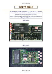
Installation and start of the <strong>LokProgrammer</strong>1. Important notes – Please read this firstThank you for purchasing the <strong>LokProgrammer</strong> set 53450/53451. With the <strong>LokProgrammer</strong> you can program ESU LokPilotandLokSound decoders.The <strong>LokProgrammer</strong> 53450 consists of two elements: Aninterface module that serves as the physical connectionbetween the PC and the locomotive, and the software thatcan be run on any PC using MS Windows. The set 53451 hasan additional USB adapter but is otherwise the same as 53450.Never was it easier to program a digital decoder than with<strong>LokProgrammer</strong>. Thanks to the graphic interface of MSWindows you can achieve the optimal adaptation of LokSounddecoders even if you have very little or no experience inprogramming digital decoders. This combination allows you toeasily manipulate and adjust the many features and propertiesof LokSound decoders with your PC.<strong>LokProgrammer</strong> also allows you to modify all sound fragmentsand sound effects stored on the decoder as often as you desire.ESU provides over 100 different sound files on the ESU website at www.esu.eu. You will certainly find the right sound foryour locomotive.Please also take note of the license agreement regardingdownloading and using the sound files contained in the appendix.This manual describes in detail how to modify sounds and whichmethods to use to achieve the desired results.We wish you lots of fun in the world of LokSound.ESU electronic solutions ulm GmbH & Co KG, March 20092. Installation and start-up of the <strong>LokProgrammer</strong>Please note the remarks regarding installation to assure thatyour <strong>LokProgrammer</strong> software keeps working to your fullsatisfaction!2.1. System requirementsIn order to use this software you need a commercially availablePC with the following requirements:• Operating system: Microsoft Windows 98, 2000 or XP, alsoVistaas from version 2.6.3; but not Windows NT• CD-ROM drive• One serial port or an USB interface on your PC• Audio card• 10MB minimum available memory on your hard discFor the utilization of the sound files with this software an AudioCard must be installed. All cards with a Windows driver aresuitable.2.2. Connecting the <strong>LokProgrammer</strong>The <strong>LokProgrammer</strong> has to be connected as shown in Figure 1:Use the serial cable respectively the USB-adapter cable providedto connect the <strong>LokProgrammer</strong> to any available COM port (orUSB-port) of your PC. Which port you select is immaterial.Please make sure that the programming track is completelyisolated from the rest of the layout to avoid possible damage ofyour <strong>LokProgrammer</strong> hardware!Also make sure that there are no electrical connectionsbetween the individual wires.Fig.1.: Wiring the <strong>LokProgrammer</strong>Fig.2.: Polarity of Power Supply ConnectorThere are two options for the power supply:• Use the power pack with mains plug provided with the<strong>LokProgrammer</strong>. Connect the output of the power pack tothe power supply terminals of the <strong>LokProgrammer</strong> as per Figure2.• Use the AC power output of a model train transformer andwire it to the screw terminals. We recommend this option forprogramming gauge 1 locomotivesNever connect both terminals at the same time. This coulddestroy the <strong>LokProgrammer</strong>!After connecting the power supply the green LED on the<strong>LokProgrammer</strong> should light up.The terminals „Track Out“ on the <strong>LokProgrammer</strong> are to bewired to the programming track. Polarity is irrelevant.Make sure that the programming track is fully isolated fromthe layout!The two LEDs on the <strong>LokProgrammer</strong> indicate the following:Green LED:• Is lit continuously when supply voltage is available.• Blinks when the <strong>LokProgrammer</strong> receives data from the PC.Yellow LED:• Blinks quickly when voltage is applied to the programmingtrack and data is transferred.• Blinks slowly if the <strong>LokProgrammer</strong> detects a high current andis disconnecting the programming track.2.3. Installing the softwareMake sure that the <strong>LokProgrammer</strong> is connected as describedabove and is ready for use.As soon as you insert the CD-ROM into the drive the installationprogram is starting automatically.Should this not be the case select the CD-ROM drive in „DeskTop“ or in the „Windows Explorer“ and click onto „Set up“.Alternatively you may click on the START button in the tool barand select „Run“. Then type „x:\setup.exe“ and „OK“. Ofcourse you must enter the name of the CD-ROM drive insteadof the „x“ (usually „D“):After a short while the program should start. Follow theinstructions on the monitor and wait until the program is installedon the hard disk.2.4. Starting the programThe installation program creates an entry in the start menu.Select „<strong>LokProgrammer</strong> vX“ in the Start menu under „Programs“;„X“ stands for the version number of the software.Select „<strong>LokProgrammer</strong>“. Then the program will start.4
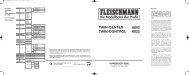
LokSound Basics2.5. Software updatesESU offers the latest version of the <strong>LokProgrammer</strong> softwareon the web page www.esu.eu. You will find it in the „Downloads“menu under „Software“. Click onto the Downloadsymbolat the end of the line. A window opens. Click „Run“.Now the program will guide you through the installationprocedure.Fig.3.: Start Window for Internet UpdateThere is also an option for an automatic update provided thesoftware is already installed on your computer:• Go into the Start Menu and select Program „<strong>LokProgrammer</strong>vX“, (the X stands for the version number of your software).• Click onto „Internet Update“. A window as per Fig. 3 opens.• Click onto „Next“. The note „Downloading required Files. Pleasebe patient“ appears. While this window is shown the filesrequired for the update will be installed. Subsequently you canstart the <strong>LokProgrammer</strong> software from the installationwindow.Please note that software version 2.6.6. only runs and opensappropriate data (meant for version 2.6.6. and all followingupdates). The software doesn´t run former or previous versions(before version 2.6.6).2.6. Firmware updatesThe firmware is the operating system of the LokPilot- orLokSound decoders.Please note: Certain new software options can only be activatedwith LokSound decoders with the latest firmware-update.You will find the latest firmware-updates on our website atwww.esu.eu under „Download“ and „Software“.Update procedure:• Connect the desired decoder to the <strong>LokProgrammer</strong> and startthe update.• Select „Run“ in the pop-up window.• Follow the instructions for installation.• First the firmware-update will be installed on your PC, then theupdate will be downloaded onto your decoder.Privacy Protection:ESU guarantees that no information will be downloaded fromyour PC to the ESU website. Data transmission is strictly limitedto sending data from the ESU home page to your PC. Yourpersonal data are protected at any time.3. LokSound basicsIn the following chapter it is explained how the LokSounddecoder reproduces prototypical sounds, what options areavailable with digital command control for model trains andwhich protocols of digital systems are currently available in themarket. Should you already have experience with digital systemsand also be familiar with locomotive sounds you may skip thischapter and continue reading on page 16.3.1. Sound characteristics of locomotivesWith <strong>LokProgrammer</strong> and LokSound decoders you canreproduce sounds of steam locomotives, diesel-hydraulic anddiesel-electric locomotives, electric locos or locos with manualtransmission (e.g.: rail car). Of course the sound sequences aresubject to the type of locomotive.3.1.1. Steam locomotiveThe dominant sounds of a steam locomotive are the hissing ofthe boiler and the exhaust chuffs when the locomotive isrunning. The chuffs are synchronized to the revolutions of thedrivers and therefore accelerate or slow down whenever thelocomotive runs faster or slower. We differentiate betweenlocomotives with 2 or 4 cylinders and others with 3 cylinders. Asteam locomotive with 3 cylinders generates either 3 or 6exhaust chuffs per revolution of the drivers while a 2- or 4-cylinder locomotive generates 4 exhaust chuffs per revolution.The exhaust chuffs appear to be louder and harder duringacceleration compared to normal running at constant speed.Whenever the valves are closed the only audible noise is theclank of the driving rods.When the locomotive starts moving, the cylinder valves areopen in order to push out any condensed steam and thus toavoid breakage of the driving rods.This behaviour can be simulated with LokSound decoders andwith the aid of the <strong>LokProgrammer</strong>. The individual stages aredivided into separate Driving notches. The different sounds ofthe respective stages consist of individual recordings of theexhaust chuffs (also refer to Fig. 4 and chapter 9.4.1 fordetailed explanations).Fig.4.: Performance of a Steam Locomotive3.1.2. Diesel locomotive (diesel-electric)Diesel-electric locomotives are in principle electric locomotiveswith electrical generators that are powered by diesel engines.The diesel locomotive is generally driven at constant Drivingnotches subject to the speed of the locomotive. Therefore thenoise generated changes (driving) step by (driving) step. Thequiet electric motor can hardly be heard over the noise of thediesel powered plant. Most diesel-electric locomotives have 4to 8 throttle notches. The <strong>LokProgrammer</strong> can handle up to 10throttle notches plus one each for acceleration and idlerespectively coasting (for more info please refer to chapter12.3).Examples of diesel-electric locomotives are the DB class 232(„Ludmilla“), most American diesel locomotives by GE or ALCOor the MZ-locomotives by the Danish State Railways.Fig.5.: Performance of a diesel-electric locomotive5
LokSound Basics3.3. Automatic / Random soundsRandom Sounds are triggered automatically and irregularlyand can be used for safety valves, fans, compressors, etc.With the <strong>LokProgrammer</strong> you can select the time betweenRandom Sounds (details in chapter 8.5.3).Other possibilities for triggering sounds automatically such assquealing brakes are contained in Function Mapping and thesound schedule (see chapter 9). Such sounds will be triggeredat specific times.3.4. Digital system / ProtocolsIn this chapter we list all digital protocols for running modeltrains and setting signals and turnouts that are supported bythe <strong>LokProgrammer</strong>.3.4.1. DCC (NMRA)DCC stands for „Digital Command Control“ and was formulatedas standard by the NMRA (National Model Railroad Association).In the early stages operation was limited to 14 speed steps and80 addresses; today up to 10,000 addresses and 128 speedsteps are available.DCC is downward compatible in terms of control and decoders,e.g. older decoders can be controlled with up-to-date commandstations / throttles and with certain limitations new decoderscan be operated and programmed with older control devices.3.4.2. Motorola®The Motorola®-protocol goes back to 1984 is one of the oldestdigital systems for model trains. Due to its age the operationaloptions are limited.The Motorola®-protocol can only handle 80 locomotiveaddresses with 14 speed steps and besides the headlight functiononly four additional function outputs can be controlled (functions5-8 can be selected with the second Motorola®-address).Since the Motorola®-protocol is still used in many digital systemsESU decoders are designed to work with this protocol as well.3.4.3. M4Since 2004 the MFX®-system is on the market. Theoreticallythis could run more than 16,000 model locomotives simultaneouslywith 128 speed steps.The <strong>LokProgrammer</strong> software deals with certain settingssomewhat differently to DCC.For instance, instead of locomotive addresses the name of thelocomotive has to be entered (e.g.: „class 01“ or „ICE“). Theallocatement of certain parameters to the CVs is also differentto DCC.Do not use the DCC-CVs mentioned from chapter 3.5 onwardsfor M4!What does M4 mean?At some points in this manual you will notice the term „M4“ for the firsttime and rightly wonder what this might mean.This question can be answered quite simply: from 2009 forward, M4 is thename of a data protocol that was chosen by ESU to be implemented intheir decoders. Decoders with the M4 protocol are one hundred percentcompatible with command stations using mfx®. At such stations (e.g.Märklin® Central Station®) they will be recognized automatically and allplaying functions are available just like when using mfx®. On the otherhand, our ESU command stations using M4 will recognize all (Märklin®and ESU) mfx® decoders without any restrictions and will still workwithout any problems. As the (mutual) inventor of mfx® we can assureyou of this.In short: the technique stays the same, only the name has been changed.3.4.4. Selectrix®Selectrix® is another digital system. In contradiction to DCCthe locomotive addresses are not transmitted individually but ingroups. Thus it is limited to the driving sounds and RandomSounds but it is not possible to trigger any user defined sounds(e.g.: a whistle or bell). Selectrix® is almost exclusively used forN scale and Z scale; therefore it is also supported by the ESULokSound micro decoder.It is important not to confuse these systems when programmingany sounds. For instance is it not possible to store any M4-project files on a DCC-decoder let alone to replay them.3.5. CVs3.5.1. Definition and applicationCV stands for „Configuration Variable“. CVs can have values inbits or bytes. The CVs with bytes can have a range from 0 to255 while the CVs programmed in bits function as on / offswitches.Examples:CV 63 (sound volume) is a CV that can be programmed bytewisewith a maximum value of 64. The value 0 means no soundwhile 64 stands for maximum sound volume.In CV 49, bit 0 is a „switch“ for activating load compensation(as per 8.3.2). Is this bit set to 0, load compensation is deactivated,is it set to 1, and then load compensation is active.The NMRA (National Model Railroad Association) has allocateedcertain CVs to certain functions. For instance CV 1 is alwaysused for the address, CV 5 for the maximum speed.3.5.2. Advantages / DisadvantagesDigital decoders can be programmed without the need ofcomprehensive programming knowledge or equipment. Manydigital command stations also offer internal programmingmenus.Furthermore the programming with bits and bytes requireslittle memory space. Programming solely with CVs is not easy toremember and depending on the type of command station itcan be quite cumbersome.Furthermore CVs have only limited effect on sounds in LokSounddecoders (e.g.: sound volume). The actual sounds cannot beadjusted with CVs but depend on the actual sound recording.In the <strong>LokProgrammer</strong> software CVs are shown in registers oras slide controls and can therefore easily be set to the desiredvalues.3.6. Further information about LokSound decoders3.6.1. GeneralAt the core of a LokSound decoder is a powerful processor. Itis supported by an audio amplifier and a sound memory thatcan store up to 130 seconds of sound.The four channel mixer with active filter can replay four differentsounds simultaneously: One channel is reserved for thedriving noises while the other three can be used for User Sounds(such as bells, whistles, etc.) and Random Sounds (e.g.:automatic safety valves or shovelling coal). All four channels willbe mixed to one output in the decoder and transmitted to thespeaker.The memory of the LokSound decoder can be deleted at anytime to make room for new sounds. Thus it is no problemwhatsoever to modify a steam sound decoder into diesel sound.You can easily do that yourself with the aid of the ESU<strong>LokProgrammer</strong> whenever you want to!Please note: this unimpeded change of sounds is limited todecoders sold for installation into locomotives by the user.LokSound decoders that are installed in locomotives by a modeltrain manufacturer may not always offer this option!A field at the lower edge of the screen shows the availablememory space during programming (in seconds and bytes) aswell as the total capacity of the particular decoder. Select the„Sound“ register and then one of the sound displays in orderto see this (also refer to chapter 9.).If you wish to save some files but do not have enough memoryspace on the decoder you may have to delete some sound filesfrom this project. Alternately you can shorten some of thesound fragments with your audio-program.3.6.2. Connecting the speakerThe speaker is the end piece of the sound equipment. Ofcourse we can only install small speakers into our modellocomotives.Therefore the speaker must meet a very demandingspecification. ESU offers a range of speakers of different sizeand for different decoder types.Please note that the audio output of the LokSound decoder isdesigned for 100 Ohm speakers. Speakers with other resistancevalues may cause overheating of the amplifier in the decoderor simply result in lower sound volume.If you wish to install two speakers in one model it is best to usetwo 50 Ohm speakers in series.7
Tasks of the <strong>LokProgrammer</strong> Software3.6.3. Suitable soundsESU offers many different sound files for all sorts of locomotiveson the website www.esu.eu. Please take note of the licensingconditions mentioned in the appendix regarding the downloadof sound files. Of course you can program your own soundprojects on your LokSound decoder.Generally you may use all files in Windows *.wav-format forLokSound decoders. WAV is the standard format for storingsounds of any kind on windows. If the recording is noise, musicor speech makes no difference.The files can originate from the CD-ROM supplied with the<strong>LokProgrammer</strong>, they could be downloaded from the internetor they could be created by you.Wave-files can be stored in different levels of sound quality onthe hard disc. The better the sound quality, the more memoryspace is required.In order to achieve optimal sound quality you should use wavefiles that match the respective LokSound decoder:Sampling frequency: 15625 Hz(corresponds roughly with doubleThe displayed hearing frequency)Resolution (corresponds with volume driving steps): 8 BitNumber of channels: 1 (Mono)The program automatically converts the files to the suitableformat matching the particular decoder. However, under certaincircumstances this could lead to lower sound quality.Hint:It would be best to prepare the wave file by adjusting them tothe above mentioned sampling frequency, resolution andnumber of channels matching the corresponding parametersof the decoder.Firstly, this helps to save memory space while assuring the bestpossible sound quality. Secondly, one can appraise the soundsbest during the preparation phase.There are a number of programs for generating wave files.The best known ones are Windows-Media Recorder forrecording sounds and to save them in digital format as *.wavfile on the hard disc. There are also more sophisticated audioeditors that offer professional features such as tone control,echo, editing, etc.It is recommended to record sounds with hard discs or otherhigh fidelity audio recorders in order to achieve a high level ofsound quality. Cassette recorders or even worse dictaphonesare not suitable.In this manual we cannot provide comprehensive instructionson how to convert sound to digital files and how to save themon a hard disc. Please observe the manuals that were suppliedwith your PC or with your audio card.3.6.4. Supported hardwareThe <strong>LokProgrammer</strong> software as from version 2.5.0 supportsonly the <strong>LokProgrammer</strong> 53450 „<strong>LokProgrammer</strong> V3.0“. Usingthis software with older versions of the <strong>LokProgrammer</strong> (e.g.:50450) is currently not possible.The number of supported decoders varies subject to the<strong>LokProgrammer</strong> version.The versions as from 2.6.1. support the following ESU-decoders:• LokSound V3.5 with 8 and 16 MBit memory for 0 scale and H0scale (DCC and Motorola®)• LokSound micro for TT and N scale (DCC, Motorola® andSelectrix®)• LokSoundXL V3.5 for G and I gauge (DCC and Motorola®)• LokSound M4 for 0 and H0 scale for the users of Märklin®systems.In addition the following (partly older product versions) aresupported:LokSound V3.0, LokSoundXL V3.0, LokSound2, LokSoundXLV2.0, LokPilot, LokPilotDCC, LokPilotXL, LokPilotXL DCC.The <strong>LokProgrammer</strong> software is subject to continousdevelopment. In order to assure that you always work with thelatest software version you should regularly call up the internetupdate facility. Whenever a new version with extendedfunctionality and bug fixing is available it will be placed in thedownload section on our website.The appearance on the screen may change subject to thefeatures of a specific decoder. Therefore in certain cases onlysome of the features described here will be active or evenmore options may be available. Please always refer to themanual supplied with the decoder.4. Purpose of the <strong>LokProgrammer</strong> softwareIn the following chapters the program functions of the<strong>LokProgrammer</strong> will be described. First the general functionsand then the more special possibilities of adjusting ESU decoders(LokPilot and LokSound).The appropriate CV in the DCC protocol for each option will benamed as well as which setting is supported by which ESUdecoder. LP stands for LokPilot, LS for LokSound.Please bear in mind that you can only fully utilize the potentialfeatures of a decoder with the latest firmware.4.1. Overview• Setting / changing of all parameters of ESU decoders: all optionscan be set comfortably on the PC. Of course it is still possible tomanually adjust any CV via digital command stations such asthe ESU ECoS-command station.• Modification of sound files, that are stored on an ESU LokSoundmodule: it is possible to change all sound files on the LokSoundmodule at any time, e.g. also at a later stage. Thus you cancompose your own sounds using anything as source that canbe saved on your PC: locomotive sounds, music, speech, etc.There are no limits to what you can do.It is for instance easily possible to change the sounds from asteam locomotive to a diesel or electric locomotive - or viceversa.• Test new ESU sounds: With the aid of the virtual cab (seechapter 6) you can test decoders on the programming track.4. 2. AssistantAs soon as the software is started the assistant window popsup on the monitor. This enables you to call up the most importantfunctions of the program. Subject to which function you selectthe appropriate window appears immediately. With the helpof the assistant you can deal with important tasks easily andquickly.The assistant helps you to carry out the following tasks:• To read out decoder data for comfortable evaluation andmodification.• To completely modify the sound files of a decoder in order toeasily change a steam sound decoder into one for a diesellocomotive.• To generate a completely new project• To open an already saved project.In order to do this, select the desired option and follow theinstructions in the small windowFig.9. Assistant8
Main Screen5. Main screen5.1. RegistersAccording to the different tasks of the program it is divided intodifferent registers and menus. Figure 10 shows the main screenof the <strong>LokProgrammer</strong> software and its main components:• Virtual Cab: Here you can test decoders in an easy manner• Modifying CV’s: individual adjustment of CVs provided thedecoder supports DCC (NMRA).• Decoder: for comfortable programming of ESU decoders witha graphic display• Sound: this serves for modifying sounds or to generate newsound compositions for LokSound decoders.You can also call up the internet update facility (refer to 2.5)and close the <strong>LokProgrammer</strong> software.During „Saving“ all data, settings and sound files will be writteninto the project file. Project files are saved with the ending„.esu“.• Programmer: here you can read and write decoder data andread sound files and allocatement of addresses. Extendeddecoder data such as type of decoder and version number ofthe firmware can also be read here.5.3. Tool bar„Add Sound File“. This button is only active when a sound filewas selected in the window „Folder“ or at the „Sound“ register.„Delete Sound File“. This button is only active when a soundfile was selected in the window „Project Sound“ or at the„Sound“ register.„Play Sound File“ for testing purposes. This button is activewhen a sound file was selected.„Play Sound File continuously“. This button is active when asound file was selected. This type of replay is useful for soundloops (driving noises).„Stop Playing Sound Loop“. This button is active when a soundfile was selected.Fig.12.: Menu „Programmer“It is possible to first listen to sounds on your PC prior to addingthem to a project. Mark the file you want to listen to in thewindow „Folder“ (in the window „Sound“ / „Schedule“ in thelower half of the left column). Then click ontoor .5.2. Task ask barFig.10.: Main screen• Editing: in this menu you can enter additional info such as thename of the locomotive or a photo and description of thelocomotive. It is also possible to convert LokSound 2 project filesinto the current format of the <strong>LokProgrammer</strong>. After thisprocedure you may have to check the CV values since not allCVs can be transferred.• Settings: here you can determine the project directory and theprogramming language (German or English). Please note thatthe new language only operates after restarting the program.• Help: here you can open this manual and obtain otherinformation on this softwareTo finish click onto .In this manner you can also listen tosounds that are already contained in the list „Project Sounds“.„Read Decoder Data“: Prior to changing any data on thedecoder it is advisable to read out all decoder data. Place thelocomotive on the programming track and make sure theprogramming track is correctly connected.Then click onto „Read CVs of the Decoder“ in the task bar atthe top of the screen. Alternately you can select the command„Read out Decoder Data …“ in the menu „Programmer“. Theprogram starts to read the data immediately. Please be patient,this process may take one or two minutes.The status is displayed in the progress bar.Should the program not be able to read the data please referto chapter 13.1.Fig.11.: Task bar•File: in this menu you can do the following with projects:Generate a new project,load resp. „open“ a new project, save a projectPlease note that all files of the <strong>LokProgrammer</strong> software version2.6.6. can only be opened and changed when software version2.6.6. is used!„Write Decoder Data“: The CVs contained in the project filewill be written onto the decoder connected to the<strong>LokProgrammer</strong>. Click „Continue“ in the window that opensfirst in order to write the CVs.All data on the decoder will be replaced by the new data.9
Virtual Driver’s Cab„Write Sound Files“: This button enables you to write the soundfiles contained in the project file onto the decoder connectedto the <strong>LokProgrammer</strong>. Click „Continue“ in the window thatopens first in order to write the sound files. Depending on thesize of the file and the size of the memory this may take up to10 minutes.Please bear in mind, that you have to write the CVs onceagain, if you have made any changes.„Write Address Allocations“. Any data contained in the projectfile regarding the allocation (e.g.: sound slots to function buttons)will be written onto the decoder.The following fields next to the tool bar are of purely informativecharacter:This field shows the decoder type connected to the<strong>LokProgrammer</strong>. In this example it is a LokSound decoder version3.5. Of course you can work with any LokSound decoders (asfrom LokSound 2 upwards), as well as LokPilot-types in DCC(NMRA), Motorola®, M4 and Selectrix ®.This field shows the size of the sound memory of the decoder.Depending on the type this could be 1Mbit, 2Mbit, 4 Mbit(LokSound 2), 8Mbit or 16Mbit (LokSound 3.5).6. Virtual driver’s cabWith the aid of the virtual cab you can test decoders. You canrun the locomotive and trigger all functions. Therefore you cantest run your locomotive on the programming track with the<strong>LokProgrammer</strong>.There are some limitations, though: the <strong>LokProgrammer</strong> limitsthe permitted current to about 400 mA. Should the motor ofthe locomotive draw a higher current then the over currentprotection will be triggered and the power to the programmingtrack will be shut off. This is indicated by the blinking yellowLED on the <strong>LokProgrammer</strong>. In this case deactivate the virtualcab and then turn it on again.All other functions in this register are self explanatory: You canenter the address and the number of speed steps. Please makesure that the speed steps matches the ones set on the<strong>LokProgrammer</strong>.The <strong>LokProgrammer</strong> can run locomotives in DCC format, asfrom version 2.5 also in the Motorola® format. Due to thehardware the <strong>LokProgrammer</strong> cannot handle M4. Test yourM4 projects in the Motorola® format.Please check that your programming track is fully isolated fromthe mainline of your layout prior to turning on the virtual cab.Should there be any electrical bridge it could damage the<strong>LokProgrammer</strong> (also refer to 2.2.)!Activate the locomotive for the test run by clicking the field„Activate Cab“.Control the speed of the locomotive with the slide throttle.Clicking into the appropriate fields turns functions on and off.Up to function F12 you may also press the numbers on yourcomputer keyboard.Please bear in mind that running a locomotive with the<strong>LokProgrammer</strong> cannot and should not substitute a commandstation: due to the limited power of the power pack you willnot be able to run more than one locomotive at any one time.The virtual cab simply gives you the opportunity to quickly testrun your locomotive.7. Edit CVsIn the register „Edit CVs“ you can read or write individual CVs.Select the register „Read / Write CVs“.Write a CV:• Enter the number of the CV you want to write in the field atthe top.• Write the new value of the CV in the lower data entry field.• Click onto the button „Write CVs“.• The CV will be overwritten with the new value.You can also read out the manufacturer’s code. Simply clickonto „Read Data“.Please bear in mind that any changes made here are notautomatically displayed under „Decoder“. You must first readout the decoder data (also refer to chapter 5.3).You will find a comprehensive list of CVs in 13.1.8. The „decoder“ registerAll settings regarding the motor control part of the decoderare handled in the „Decoder“ register. Please note that thisregister is initially empty when you start the program. Info willonly be displayed in this field after you have generated a newproject, opened an existing project or read out a decoder.Projects are an image of all data stored on a decoder.Fig.13.: Virtual Driver’s CabFig.14.: Subwindow „Edit CVs“Read a CV:• Enter the number of the CV you want to read in the upperdata entry field.• Press the button „Read CVs“.• The result will be shown in binary and decimal format.Fig.15.: The „Decoder“ registerThe buttons that let you go to the different options are on theleft of the screen. Besides movement and sound behaviour youcan adjust specific settings such as brake mode, address, etc.On the following pages we will explain the parameters andoptions.10
Subwindow „Decoder“8.1. View window „address“8.1.1. Address (CV 1, CV 17, CV 18)All modifications of the address are done in the window„Address“. Subject to the decoder type so called short (twodigits, CV1) or long addresses (four digits, CV17 and CV18) canbe used.Please note that any settings in these CVs are only effective foroperation with NMRA-DCC compliant command stations.When operating decoders with the Märklin® / Motorola®protocola separate address, namely the Märklin®-address isvalid.You may enter a second address for M4-decoders in Motorola®mode in order to activate F5 to F8. Normally this would be theaddress of the decoder plus 1.8.1.2. Consist settings (CV 19)The DCC consist address is useful for multiple traction. It is alsopossible to activate function outputs for consists as well asfunction buttons for consist mode.In some cases it is desirable to set certain functions in consistmode in such a way that the function is actually triggered bypressing one button in both (or all) locomotives (e.g.: lights).Click onto the appropriate button of the function that shouldbe activated in consist mode.8.2. Driving characteristics8.2.1. Selecting the number of speed steps (CV 29,CV 49)Here you can adjust more settings for running your locomotive.In DCC mode you have to first set the number of speed steps to14, 28 or 128 or alternately to automatic detection of speedsteps.8.2.2. Reverse mode (CV 29)A tick at „Reverse mode“ changes the direction of travel andthe directional characteristics of the headlights. This is useful incase the wiring has been done incorrectly (swapping of trackleads or motor leads).8.2.3. Acceleration and deceleration (CV 3, CV 4)This option allows you to set the acceleration time (CV3)respectively the braking time (CV4). The time is calculated bymultiplying the CV-value with 0.869 seconds.The acceleration time is the time the locomotive takes fromstop to maximum speed. Of course the acceleration time fromstop to mid speed is accordingly shorter.The same is valid for the braking time. This is the time frommaximum speed until the locomotive stops.8.2.4. Supported brake modes (CV 51)Here the brake modes can be selected. The <strong>LokProgrammer</strong>supports the Märklin®-, Zimo- and Lenz-brake modes.8.2.5. Trim (CV 66, CV 95)The trim function allows you to set the maximum speedseparately for forward and reverse movement. The factorthat is used to multiply the motor voltage, results from dividingthe CV-value by 128 (forward CV 66 and reverse CV 95).8.3. Motor8.3.1. DC motor PWM frequency (CV 49)Here you can select the desired tact frequency for motor control(pulse width modulation). The possible values are 15kHz and30kHz. LokSound decoders as from V3.5 are normally set to30kHz.8.3.2. Load compensation (CV 49, CV 53, CV 54,CV 55 and CV 56)Load compensation helps to adjust the motor power in case ofobstructions such as gradients.First of all you may decide if you want to use load compensationor not (CV 49). Then you can set the reference voltage (CV 53)and the two control parameters K and I (CV 54 and 55).Furthermore you can set the impact (effectiveness) of loadcompensation (CV 56). At 100%, load compensation is activeover the entire speed range; at 50% it is only active up to halfthe maximum speed.With this setting your locomotives benefit from loadcompensation at lower speeds while their speed changesprototypically on gradients.The numbers of values respectively the values themselves aresubject to the type of decoder. For useful values please consultchapter X.1 or the user manual of your decoder.8.3.3. Speed curves (CV 2, CV 5, CV 6, CV 26, ...and CV 67-97)The field „Speed Curves“ gives you a choice of a three-pointspeedcurve or a user-defined speed curve.The three-point-speed-curve is determined by the start voltage(CV 2), the medium speed (CV 6) and the maximum speed (CV5).The speed curve has a higher resolution with 28 speed steps.Subject to the selected speed steps you can move the individualspeed points up and down with the mouse and adjust themto the most prototypical setting.The three-point-speed-curve and the individual speed curvewith 28 entries are valid for all operating modes: DCC 14, 28 or128 speed steps, Motorola® format (14 speed steps) or M4;the selected speed curve will always be adapted (interpolated)to the actual speed mode.With the choice menu „Default“ you can enter a simple linearor exponential speed curve.8.4. DCC / Analogue8.4.1. Zimo® manual function (CV 49)Activates the Zimo® manual function.8.4.2. Analogue mode (CV 29)Activates the analogue mode.8.4.3. Supported analogue modes and settings(CV 50, CV 125, CV 126, CV 127 and CV 128)In analogue mode load compensation is not active. Thereforeby using the appropriate slide control you can adapt the startvoltage and the maximum speed separately for AC or DCanalogue mode to match the characteristics of your motor ortransformer.Furthermore you can select the functions that should be activein analogue mode (DC, AC or both; CV 50).8.4.4. Analogue mode F1-F8 / Analogue mode FL,F9-F12 (CV 13, CV 14)Since most analogue layouts do not have input devices to triggerfunctions, these parameters allow you to pre-select whichfunctions should be automatically active in analogue mode.It is recommended to turn on the sound (default value F1) andthe smoke generator of steam locomotives (often F4).Furthermore the headlights in both directions would be switchedon in analogue mode (marked as FL(f) and FL(r) in the register).Functions F9 and F10 can also be set as directional functions(F9(f), F9(r), F10(f), F10(r)).11
Subwindow „Decoder“8.5. Sound settingsThis window shows the behaviour of all sounds that are relatedto the movement of the locomotive, also characteristics ofRandom Sounds and main volume control. However, we arenot talking about the actual sound files (wav-files) but theparameters that control these sound files.Of course these settings must match the type of sound filesstored on the decoder. Otherwise some absurd results mayoccur when for instance steam sounds are stored on thedecoder but the settings here are for a diesel locomotive.On the other hand there is no limit to the creative use of the<strong>LokProgrammer</strong> for achieving exceptional sound effects. Forinstance it is quite easy to insert discussions between engineerand fireman, station announcements or even music into theproject and to replay them with your LokSound decoder.8.5.1. Type of sounds (CV 57, CV 58)Selection of locomotive type (also refer to chapter 3.1.):• Diesel locomotive - hydraulic• Diesel locomotive with manual transmission• Diesel-electric locomotive or electric locomotiveHere it is possible to use only one sound file for driving and toadd extra effects with „Interval between Throttle Notches“. Itis necessary to set the „Speed of Driving sound“ to theappropriate value (also see 8.5.4) in order to make differencesin pitch audible.„Interval between Throttle Notches“ divides the speed curveinto certain sectors in which the driving noise is played at adifferent pitch. If this parameter is set to „1“ the decoder willplay the driving noises without audible throttle notches.• Steam locomotives without external wheel sensor: the exhaustchuffs can be synchronized with the revolutions of the drivers.The time between the exhaust chuffs is determined bymultiplying the value of CV 57 („Interval between ExhaustChuffs at Speed Step 1“) by 0.064 seconds.The value of CV 58 („… and at Speed Step 2“) determines thedegree of reduction of the time between exhaust chuffs withincreasing speed starting at speed step 2.Since these settings depend on the circumference of the drivers,the selected maximum speed and the motor characteristicsthey have to be determined by trial and error. The<strong>LokProgrammer</strong> in conjunction with a test oval provides thebest testing conditions.More info on synchronizing without external sensor can befound in chapter 12.2.• Steam locomotive with external wheel sensor: Steamlocomotives with external wheel sensors are very common inthe large scales such as G and 1 gauge. The parameter „TriggerPulse“ (CV 58) determines after how many pulses from thesensor the exhaust chuff will be played. The decoderdifferentiates between „On“ and „Off“ pulses. If CV 58 is setto „1“ then the decoder will play an exhaust cuff for each„On“ and „Off“ pulse. Value „2“ triggers an exhaust chuff foreach „On“ pulse while value 4 triggers the chuff for everysecond „On“ pulse. The default value is „2“. In principle thevalue can be increased up to 250.8.5.2. Minimum time between exhaust chuffs (CV 249)Normally exhaust chuffs are speed dependant. However, incase of a somewhat unfortunate configuration of wheelcircumference and maximum speed this could lead to anundesirable sound at high speeds rather like a machine gunand not like a steam locomotive.To counter this effect you can adjust „Minimum Time betweenExhaust Chuffs“. The value represents the minimum timebetween two chuffs even when the maximum speed has notyet been reached.Of course the chuffs are not synchronized to the drivers anymore at that stage but this is hardly noticeable at high speeds.8.5.3. Random sounds (CV 61, CV 62)In this field you can activate the Random Sounds and the timeintervals between them.The LokSound decoder plays the Random Sounds arbitrarilywithin these minimum and maximum intervals. The valuescorrespond with seconds (also refer to 9.5).8.5.4. Speed of driving sound (CV 59, 60)These parameters allow you to simulate the revs of the motor.The sound files for the driving sound are the basis. The value isgiven in %. 100% means original speed of the sound file,200% twice the speed. The pitch is changed subject to thespeed. One could compare this effect with a cassette playerthat is running too slowly. If you set the value of „… at thehighest Speed Step“ to 100% then the driving sound will remainconstant (provided you have only one sound file for driving).8.5.5. Brake sound threshold (CV 64)Here you determine when exactly the decoder starts playingthe brake squeal. The higher the value, the sooner the squealwill start.8.5.6. Sound volume (CV 63, CV 121, CV 122 and CV 123)The sound volume can be adjusted to match the speaker withthe slide controls.Controls 1, 2 and 3 can be used as group controls. The overallvolume (CV 63) influences controls 1, 2 and 3. Control 1 (CV121) is intended for horns and whistles, control 2 (CV 122) forbells and control 3 (CV 123) for additional sounds. This is only asuggestion. Of course you may use the controls for other soundgroups as well. The advantage of the group control is that youcould link for instance the driving noise of a steam locomotiveto one group in order to be able to adjust the volume of allexhaust chuffs simultaneously should they be too loud or tooquiet compared to User Sounds or Random Sounds.8.5.7. Load dependent sound (CV124)If the decoder registers a load – i.e.: when load compensationbecomes active – the driving noises will be played louder. Thisworks only if the overall volume is set to a lower value thanmaximum. Only then are some „volume reserves“ available.8.5.8. Sound steam shift (CV250, CV251, CV252)One can hear that the chuffs of compound steam locomotivesare generated by two drive mechanisms. The <strong>LokProgrammer</strong>achieves this effect by adding an additional exhaust chuffbetween the regular ones. This extra chuff continuously changesits timing relative to the regular chuffs.After activating „Sound Steam Shift“ the following parameterscan be edited:• Duration of steam shift: here you determine how long theshifted chuff needs to go from the earliest possible relativestart position to the latest start position and back again. Thevalue entered here is a relative value and must be determinedby testing.• Earliest relative start position for steam shift: in order to avoidthat the additional chuff is played at the same time as theregular one and thus would lead to over-modulation of thesound it is recommended to slightly delay the steam shift.This delay is set in this parameter.• Latest relative start position for steam shift: in order to avoidthat the additional chuff is played at the same time as thefollowing regular chuff and thus would lead to over-modulationof the sound it is recommended to bring forward the end ofthe steam shift. This can be set with this parameter.12
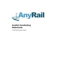
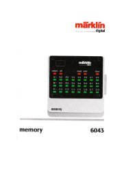
Subwindow „Decoder“Fig.16: Steam Shift Schematic8.6. Function mappingHere you can allocate functions to each function button.Depending on the decoder type there are the function buttonsFL and F1 to F15.Please note that Märklin®-Motorola® systems only supportthe buttons F1 to F4. F5 to F8, however, can be activated bymeans of a second address (see 10.4).Figure 14 provides an overview of possible settings.For allocating a certain function to a certain button tick theappropriate field at the intersection of the column „FunctionButton“ and the line „Function“.Please remember that function mapping is stored in the CVs.Therefore you should always read the decoder data first inorder to get to know the current status before making anychanges (also see chapter 5.3). The functions are allocateedwith the CVs 129 – 230 (also refer to 13.1.).You may allocate several functions to one button. You couldfor instance trigger a sound effect or other functions everytime you switch AUX1.However, it is not possible to play two or more soundssimultaneously by pressing one function button.Please note that functions can be allocateed separately forforward (f) and reverse (r) motion. Thus the behaviour of somefunctions can vary subject to direction of travel and / or differentsounds could be triggered (e.g.: directional horn signals). Ifyou wish to allocate a function for both directions simply enterthe function respectively the sound in both columns of thecorresponding function allocatement.8.6.1. Description of the matrix columns• FS(f), FS(r): Allocated functions and sounds will be activatedautomatically while the locomotive is standing and thus are notswitched with a function button.• FF(f), FF(r): Allocated functions and sounds will be activatedautomatically while the locomotive is moving and thus are notswitched with a function button.• FL(F), FL(r): Allocated functions and sounds will be activated viathe lighting button of the command station (respectively by F0in the „Virtual Cab“).• F1(f), F1(r) to F15(f), F(r): Allocated functions and sounds will beactivated via the function buttons 1-15 of the command station.In the following paragraphs the individual options (lines) in thefunction mapping register and their effects will be explained.8.6.2. Head lights, back-up lightsNormally the headlights and back-up lights are wired in such away that they are switched subject to direction of movement.Set a cross into „Headlights“ at FL(f) and another one for„Back-up Lights“ at FL(r).Now you can switch the lights with the lighting button of yourcommand station or throttle respectively with „F0“ of thevirtual cab. In Fig. 14 you see the default entry for the lights inthe columns FL (f) and FL (r) for locomotives with standardwiring.8.6.3. Aux 1-4With the aid of AUX outputs you can activate (electro-)mechanical functions of your locomotive (e.g.: smoke generator,pantograph, etc.) in accordance with the wiring.Please note that decoders with the 8-pole plug support onlyAUX 1 and 2. Decoders with the 21-pole plug „mtc“ alsosupport AUX 4. XL-decoders have 6 AUX outputs (AUX 1-6).8.6.4. Acceleration and coasting of diesel locomotivesHere you can play the idle and driving sounds while standing stilland moving. Activate the function „Accelerate Diesel“ thenthe decoder shifts from the sound of the current speed step tothe sounds of the following higher speed steps until youdeactivate this function no matter at what speed or if thelocomotive is standing still. The actual speed (or no movementif the locomotive was stationary prior to your first command)remains intact.When you trigger „Coasting“ then the above sequence will beplayed in reverse without changing the actual status ofmovement or standing still.This function serves to rev the diesel motor wile standing or tosimulate the sound of a locomotive with a heavy load (forinstance on a gradient). This function is only appropriate fordiesel-electric locomotives.It is best to allocate this function to both directions.Fig.17.: Function Outputs Matrix13
14Subwindow „Decoder“Fig.18.: Notch behaviour8.6.5. Acceleration / DecelerationThis function turns off the delay in accelerating or slowingdown as set in the window „Driving Characteristics“ (also referto 8.2.3.).This is useful when the locomotive is set to shunting mode andtherefore should respond quicker to your commands.It is best to allocate this function to both directions.8.6.6. Shunting modeThis function reduces the speed to half of the current speed. Itis recommended to allocate the shunting mode to the samefunction as the acceleration / deceleration. It is best to allocatethis function to both directions.8.6.7. Sound on / offWith this you activate all driving noises and all other sounds thatdepend on the driving noises. It is best to allocate this functionto both directions.8.6.8. Shift modeAll alternative sound slots that are parallel to the regular soundsare activated with shift mode. When shift mode is active allregular sound slots are deactivated (also refer to chapter 9.7.).Pure (electromechanical) functions are affected by this.8.6.9. Fan soundThis function activates the sound channel for the fan that runsparallel to the actual driving noise. This function is particularlyuseful for electric locomotives where you can hear the fancontinuously in the background.It is best to allocate this function to both directions.8.6.10. Doppler effectThis function simulates the so called Doppler Effect as it isheard when a train is moving away very quickly. This function ismost useful in combination with the sound of a horn or awhistle activated with the same function button (how to activatethe Doppler Effect during operation is described in chapter13.1.1.).It is best to allocate this function to both directions.8.6.11. Volume / MuteWith this function you can mute the sound and – by doubleclicking – you can set 4 different levels of the overall volume. Itis best to allocate this function to both directions.8.6.12. Dynamic brakeIn order to simulate this function, that is often present in dieseland electric locomotives, as close to the original as possible theacceleration and deceleration is reduced to half the time. It isbest to allocate this function to both directions.8.6.13. Sound slotsHere you enter the numbers of the desired user sound slots. Ifyou have already imported some user sound slots then you canclick onto the corresponding square with the right mouse button.A choice list appears showing all occupied sound slot numbersand the corresponding sound files.Fig.19.: Popup Menu for selecting the Sound Slots8.6.14. Configuration of outputs .........................(lights and AUX-outputs) (CV 113- CV 120)This parameter allows you to adjust the type and intensity ofphysical outputs.The available choices are:• Dimmer: uniform voltage is available at the output for operatingconstant functions.• Blinking light (Phase 1) / Blinking light (Phase 2)• Strobe: Stroboscopic effect• Double Strobe: Stroboscopic effect with double blinking• Fire box: generates flickering light for the imitation of the openfire box. This function makes sense in conjunction with thesound of shovelling coal.• Smoke generator: while the locomotive is stopped a smokegenerator only heats to a limited degree when operating inconjunction with driving noises. However, it operates to itsmaximum in synchronization with the exhaust chuffs duringmovement. If you wish to simulate a uniform amount of smokecoming out of the chimney it is recommended to set the outputfunction for the smoke generator to „Dimmer“.• Fade lights up and down: contrary to the setting „Dimmer“ thelights do not appear at full brightness immediately but areslowly fading up respectively down.• Mars light: Simulation of a blinking warning light mainly usedon American locomotives.• Gyro light: Simulation of a rotating beacon.• Rule 17 forward / rule 17 back-up: simulates a dimming methodof American headlights.• Pulse (limited time): lights up when activated and switches offafter a certain time automatically. The „Switch-on Period“ isset with the „Brightness“ controller.• Ditch light (Phase 1) / ditch light (Phase 2): Setting for additionalheadlights for American locomotives8.6.15. Blinking frequency of strobe effects (CV 112)The time can be set between 0.262 seconds (value 4) up to4.194 seconds (value 64) and affects all blinking effects.8.6.16. Activate LGB® mode (CV 49)All ESU decoders except M4 can be operated with the LGBmultiple train control system (MZS). This mode must be activatedhere prior to use.8.6.17. Behaviour of function buttons .................(LokSound 2 mode) (CV 49)In LokSound 2 mode all sounds and functions will be activatedwhenever the function button is pressed (on or off).8.6.18. Märklin® delta mode (CV 49)Here you can set the decoder for operation with Märklin®Delta-devices.8.7. Manual CV entryThe <strong>LokProgrammer</strong> software offers all CVs at a glance. In thisdisplay you can adjust all CVs in decimal values and save the CVlist as a text document.Change CVs manually:• Click onto the field with the decimal values of the CV you wantto change• Enter the new value• Click onto the button „Check Values and Accept“.Export CV-List as text file:• Click onto the button „Export…“• Save the file as .txt-file in the desired folder• Now you can read and print this file with any text processingprogram. Changes in this document do not affect the projectfile in the <strong>LokProgrammer</strong>.
Sound8.8. Special options (CV 124)Here you can pre-select certain options so they are availableafter an interruption of power on your layout.• „Save Direction of Travel“ activates the so called „DirectionalBit“, a Märklin®-specific term that refers to the layout-specificdirection of travel.• „Save Status of Function Buttons“ assures that all functionsrecommence their status after an interruption of power.• „Save Current Target Speed“ preserves the „old“ speed in thedecoder.• When „Accelerate after a Reset with the Programmed Delay“is set, the locomotive will accelerate as per the programmedparameters; otherwise it will „jump-start“.If a decoder supports these options is subject to the version ofthe decoder firmware.8.9. Identification (CV 7, CV 8)This read-only option provides the manufacturer’s ID (CV 8)and the internal version number of the decoder firmware (CV7). The manufacturer’s code of ESU is „151“. If you write thevalue „8“ into CV 8 then you trigger a factory-reset (defaultvalues) but do not delete the manufacturer’s ID. The value ofCV 8 will always remain at „151“. Entering value „8“ simplytriggers the reset.All LokSound types offer two user fields for any personal codes,etc. in („User-ID 1“ and „User-ID 2“).9. SoundsIn 1999 the very first LokSound „classic“ decoder alreadyoffered the feature to store real sounds and to change themat will or replace them with completely different ones. Sincethen each LokSound decoder is a platform for all sorts of soundsequences that may occur when operating railways. This universaland very flexible concept even allows to store and replaymusic or voices besides the typical railway sounds. There is nolimit to your imagination.In order to make sure that you can utilize the multiple featuresof the LokSound decoders to the optimum we will explainbelow first the general concept of the sound module ofLokSound decoders and then the specific methods of thesoftware. You should make a point of reading this introductionbefore you start any specific sound project. Withoutunderstanding the concept you may not fully realize the potentialof the software.We explain the concept based on the LokSound decoder version3.5. This is also valid for LokSound micro and LokSound XL. M4offers at least partially different features that are described inchapter 10.Older LokSound 2-decoders have perhaps less functions tooffer, but the principle remains the same. Since the LokSound2 decoder is no longer manufactured it will not be dealt with inthis manual.9.1. Concept of LokSoundThe decoder has an internal memory chip with 8 MBit (LokSoundhardware 3.3) or 16 MBit (LokSound hardware 3.5) capacity.This is enough for 69 respectively 138 seconds of digital sound.In order to achieve a continuous sound that does not stop after69 seconds we have to use a few tricks: the memory containsonly a short fragment of the motor sound (about half a second).This fragment is played as a loop in the LokSound decoder thusgenerating continuous sound.Such tricks enable us to utilize the memory space to theoptimum. The number of sounds is not pre-determined and isonly limited by the size of the memory.Generally this is sufficient to store all necessary sounds for alocomotive. A simple steam locomotive can be equipped withsound with only 20 seconds of sound fragments. That includesthe bell, whistle, air pump, etc.There are three categories of sounds: Driving sounds, RandomSounds and User Sounds (sounds that are triggered by theuser).The LokSound decoder works with a „schedule“. It contains allinformation such as when to play which sound.The different stages are connected with arrows and thusrepresent the possible changes from one stage to the next.The driving noises are stored in so called sound slots and arecalled up according to the pre-determined speed of thelocomotive.Sound Fragments of varying number are entered into the SoundSlots. There must be at least three sound fragments in eachsound slot. These three standard sound fragments are generallyused as start, middle and end part of the respective sound (alsorefer to 9.2.1.). The sound fragments do not have to fill theavailable memory space completely. At certain points (forinstance within a throttle notch) it only makes sense to enterthe sound loop of the motor.Whenever the LokSound module undergoes a change of statusthe sound fragments in the corresponding sound slots will beplayed.If there should be no sound at a certain stage or change ofstatus then the corresponding field of the sound slot mustremain empty.Empty sound slots are displayed in white while sounds slots thatcontain sound fragments are displayed in blue.Random Sounds are stored in „Extra Sound Slots“ and will beplayed according to the settings in the register „Decoder“ (alsorefer to chapter 8.5.3).User Sounds are also stored in their own sound slots. Thesesound slots are allocated to the desired function buttons infunction mapping (also refer to 8.6.).9.2. Basic methodology for working in the ..........„Sound“ register9.2.1. NomenclatureFor your better understanding we have defined the terminologyfor the three fields within a sound slot in the following chaptersas outlined below:• The starting part is called „Init“(„initial“)• The middle part is called „Loop“• The final part is called „Exit“These terms relate to the standard application of these fieldsfor ESU products (also refer to chapter 12). Regardless of theterminology you could for instance enter a loop sound into theInit field (also refer to 9.6.).For each of the three parts of a sound slot you can use differentsound files that are then played by the decoder in sequence.We call the groups-of-three in the data entry fields soundSlots. They are located within the squares in the project scheduleand in the windows „Random Sounds“ and „User Sounds“.9.2.2. Importing / Deleting sounds in projectsFigure 17 shows the lower part of the view „Sound“. In theright column („Project Sounds“) are all the sounds listed thathave already been imported into the project, in other wordsthat are to be stored in the memory.At the bottom of the left column („Folder“) you see a data treeof all folders on the hard disc of your PC. Besides the folder thisalso shows the audio files and esu.-files. If you click onto an ESUfile the data tree is expanded and shows the sound fragmentsthat are already contained in the sound files (.wav).In order to import a sound file or sound fragment from thefolders on the hard disc of your PC (or from the CD-ROMsupplied with the <strong>LokProgrammer</strong>) you proceed as follows:• Mark the file with a mouse click, keep holding the mousebutton.• Drag the file with the mouse from the folder into the window„Project Sounds“. Now the desired file appears in the list ofproject sounds.15
SoundIn order to remove a sound file from the list, proceed as follows:• Mark the file with a mouse click in the column „Project Sounds“.• Delete the file with the „Del“ button on your keyboard.In order to delete an allocation, proceed as follows.• Open the desired sound slot by a mouse click• Mark the file name of the sound to be deleted within thesound slot• Delete the allocation by pressing „Del“ on the keyboard. Theallocation will be deleted but not the file in the list „ProjectSounds“. Thus this sound may still be used within the project.Fig.22.: Menu „Extended Settings“ for Steam LocomotivesFig.20.: Lower Part of „Sound“ Window9.2.3. Allocate / Delete sounds to (from) sound slotsAll sound fragments that you want to allocate to differentsound slots must first be imported into the list „Project sounds“.Only sounds from that list will ultimately be transferred to theLokSound module.A sound is allocated to a sound slot by doing the following:• Open a square (throttle notch, random sound or user sound) towhich you want to allocate a sound with a mouse click.• A pop-up window opens as shown in Fig. 21.• Mark the desired file in „Project Sounds“ and keep holding themouse button.• Drag the sound into the desired field in the pop-up window.A simple option of allocation:• Mark the desired .wav file in „Project Sounds“• Drag the file onto the desired (but yet unopened) square. Thesound will be automatically imported into the „Loop“. Thesquare changes its colour from white to blue.• This option is only suitable for sounds that have to be importedinto the loop section of the sound slot anyway (e.g.: drivingnoises in loop mode or individual user sounds without Init- orExit-part).Fig.21.: : Sound Slot „D1“ (opened)9.2.4. Extended functions in the „Sound“At the top left corner of this window there is another tool barwith the following functions:Set project as steam locomotive. This button is linked to theparameter „Type of Sound“. (also refer to 8.5.1.).Set project as diesel locomotive. This button is linked to theparameter „Type of Sound“.Set project as electric locomotive. This button is linked to theparameter „Type of Sound“.Edit motor. You can see and edit the schedule of the drivingnoises. This button is active for all locomotive types.Edit fan motor. The schedule of the fan sound channel will beopened (also refer to chapter 9.3.2.).Further settings: Here you can edit auxiliary functions thatrelate to the schedule of steam locomotives and user sounds.Thus you can set user sound slot 16 for the braking sound. Usersound slot 15 can be used for an automatically triggered soundafter the locomotive has stopped, such as an air pump ofsteam locomotives. User sound slot 14 can be used for shiftsounds (for instance for diesel locomotives with mechanicaltransmission). This does not only play the sound of shiftinggears but also the prototypical change of the revs of thelocomotive (also refer to 9.6.).For diesel and electric locomotives only the field „Trigger SoundsAutomatically“ is available.Add throttle notches. Depending on the number of differentavailable throttle notch sounds you can import up to 5 forsteam locomotives or up to 10 for diesel and electric locomotives.These throttle notches do not correspond with the 12 resp. 28or 128 speed steps of the digital protocols. The throttle notchesof your sound schedule will be equally divided across the entirespeed range of your command station.Import at least one sound file into all throttle notches you wantto use otherwise one could hear a silent gap between throttlenotches when the locomotive is running.Fig.23.: Pop-up Menu for selecting Throttle Notches9.3. ScheduleThis and the following chapters outline the rules and possibilitiesregarding the composition of sounds.After having imported various sounds into the sound slots it isnecessary to determine when each sound should be played. Allnecessary information is contained in the schedule. 9.3. Ablaufplan.16
SoundFig.24.: Excerpt of Schedule9.3.1. Schedule for running (driving) soundsThis displays a graphic representation of all possible states of alocomotive:• „M“ (=“Mute“ or silent) stands for a stationary locomotivewith the sound turned off. No sounds have to be importedhere.• „MS“ (=“Mute to stop“) stands for a stationary locomotivewith the sound turned on. This sound slot has two fields thatwill be played in sequence (if they are both filled). This enablesyou to play a two-part sound with one start, middle and endpart each simulating the starting of the motor. Here you wouldimport the sound of the starting diesel engine or the raising ofthe pantograph of an electric locomotive.• The sound slot „SM“ (=“Stop to mute“) contains „parking“sounds such as turning off the diesel motor or lowering thepantograph. You could also add a valve releasing compressedair. There is no limit to what sounds you might want to play.• „S“ (=“Stand“) stands for a stationary locomotive with thesounds in idle (e.g.: the hiss of steam or the sound of an idlingdiesel motor). There are two sound parts. It is important toknow that all sounds in step 2 are automatically played in loopmode. However, you can change this if needed.• In the stages „Dx“ (=“Drive“), the locomotive is moving andplays the appropriate sounds. „x“ indicates the number of thethrottle notch.Depending on the type of locomotive there may be up to 10„D“ notches. Thus it is possible to allocate the sound recordingsof different notches to the corresponding speeds of thelocomotive.• Status „A“ (=“Acceleration“) is reached when the locomotiveaccelerates. For the decoder acceleration means the targetspeed is higher than the actual speed.An example: Acceleration of the locomotive has been set to10 seconds. The locomotive is moving slowly and you turn upthe throttle to maximum. Then the locomotive will accelerateaccording to the corresponding settings for acceleration. Duringthis phase only the sounds imported into sound slot „A“ will beplayed.Thus it is possible to use particularly powerful exhaust chuffs ora hard working diesel motor during acceleration. In sound slot„A“ the appropriate sounds for each speed (notch) will beplayed. Depending on the type of locomotive up to 10 „A“notches are available. As soon as the target speed is reachedthe decoder shifts into stage „D“.• „CX“ (=“Coast“) is reached when the throttle is turned backand the locomotive is coasting. Similar to the acceleration delaysthat affect sound slot „A“ the braking delays affect sound slot„CX“.There are also transition notches since the transition from onesound loop to the next would otherwise be to abrupt.•„DA“(=“Drive to acceleration“) is the transition betweendriving at constant speed and acceleration. Here one couldplace a howl of a motor when it starts revving up.• „AD“ (=“Acceleration to drive“) is the transition fromacceleration back to driving at constant speed. This drivingstep is not available for steam locomotives since we use thesame chuffs for DA and AD.• „DC“ (=“Drive to coast“) is the transition from driving tocoasting.• „CD“ (=“Coast to drive“) is the transition from coasting todriving. This step is not available for steam locomotives sincewe use the same chuffs for DC and CD.Please note that you have to import one transition for eachdriving notch to avoid any hard transitions or „crackling“ noises.• „SD“ (=“Stop to drive“) is the sound at start of movement.The two sound fragments are played in sequence in differentstates of motion: the first sound is played shortly before thestart, when the locomotive is still stationary; the second part isplayed just after the locomotive started moving. The divisioninto two parts is particularly meaningful for howling diesel motorsor humming electric motors; it generates a very prototypicalimpression of movement and its associated sound.• „DS“ (=“Drive to stop“) is the transitional sound of the motorduring stopping.• „CS“ (=“Coast to stop“) is the transition from the coastingsound to the stop sound (locomotive has stopped, motor is stillrunning). Often there is no audible change between CX and S.Import the sound for idle into CS in order to avoid an audiblegap in the schedule.Fig. 25: SD-Performance• In diesel and electric locomotives there are two more transitions,namely „Dxy“ and „Dyx“; „x“ stands for the number of theprevious drive notch and „y“ for the number of the followingone.Should you not wish to utilize the option of having differentsounds for acceleration and slowing down (perhaps becauseyou do not have any suitable sound fragments) then you canlock the sound slots „A“ and „CX“ (also refer to 9.3.3.) or youcan use the same settings as in sound slot „D1“. Sound slot„D1“ must have an entry otherwise no driving noises will beplayed at all.9.3.2. Schedule for fan soundsIn most electric locomotives there is a fan which runs parallel tothe traction motors. Therefore we have introduced a separateschedule for the fan sounds that can be opened with thebutton in the small tool bar in the „Sound“ register. Thisschedule contains one step for the stationary locomotive aswell as four driving notches for the moving locomotive. These 4driving notches are independent of the notches of the drivingnoises and are equally divided over the entire speed range.• The driving notches „M“, „MS“, „SM“ and „S“ describe thesame stages as in the schedule for running.• „Rx“ stands for the fan notches with „x“ being the number ofthe individual notches. There are 4 driving notches for the fanequally divided over the entire speed range. If you want to runup the fan to maximum speed then you must enter soundfragments into all „R“ driving steps. If you want the fan toremain at a constant level from a certain speed onwards youmust import the same sound fragments into the remaining„R“-running steps to avoid an audible gap.• „SR“ respectively „RS“ are the transitional running notchesbetween start and stop (analogue to „SD“ and „DS“ in theschedule of the driving noises).• „Rxy“ respectively „Ryx“ are (analogue to „Dxy“ and „Dyx“)the transitional running notches between the individual fanrunning notches with „x“ being the number of the previousrunning notch and „y“ for the following one. Of course you canimport other parallel driving noises into the fan schedule if youwish to do so.17
Thresholds on the sound schedule9.3.3. Thresholds in the schedule for running ......(driving) soundsIn order to be able to play the driving noises correctly for eachsituation the LokSound decoder uses thresholds. Thesethresholds define the limits where the sound should change.The LokSound decoder differentiates between two types ofthresholds:• Thresholds that divide the speed values between stop and themaximum speed. These values range from 0 to 255 and areshown in a horizontal arrangement in the driving sound schedule.• Thresholds that work according to the difference betweentarget speed and actual speed. Here the decoder comparesthe current speed of the motor with the target speed as givenby the command station resp. the throttle. These thresholdsbecome effective whenever the locomotive accelerates orslows down and have a range between -128 to 127 (including 0).• Time parameters that determine the time between idle andre-entry of the driving sound. The following illustration providesan overview on how to deal with thresholds:Example: Your project has 4 driving notches that are equallydivided over the entire speed range between 0 and 255 („63“between D1 and D2, „127“ between D2 and D3, „191“between D3 and D4). You slowly increase speed in DCC mode(DCC 28). The driving sounds will change between driving notch7 and 8, 14 and 15 and 21 and 22 provided the speed curve islinear.The value 15 has been entered between step D1 and DA1 (alsorefer to Fig. : 26). You drive your locomotive in speed step 1(DCC 28 mode) and then accelerate to speed step 10 (thisroughly corresponds with the internal value 91). The differenceof the internal values between target speed and actual speedis about 82 (for a range from 0 – 255 instead of 0 – 28) andtherefore greater than 15. Thus the decoder changes from D1to DA1 and subsequently to A1 because the difference is alsogreater than 16.The decoder accelerates and passes the threshold betweenD1 and D2. Furthermore it continuously reduces the difference.Once the difference is less than 2 the decoder changes againto the corresponding DA step (in our case DA2) and reaches D“once the difference is less than 1.The decoder changes the sound speed step from 1 to 2 when reaching appr. half the speed (127 of 255)Target speed – actual speed > 16=> Decoder changes to A1 Target speed – actual speed. < 2=> Decoder changes to DA2Number of repetitionsFig. 27: Path of Sound during Acceleration9.4. Setting the schedule9.4.1. Soundslots in detailAs soon as you click onto any square of a sound slot with themouse a pop-up window opens as shown in figures 28 and 29.In order to make editing very easy this window shows theindividual sound slots in detail.Target speed – actual speed - > 15 Target speed – actual speed. < 1=> Decoder changes to DA1 => Decoder changes to D2Target speed – actual speed > -1 Target speed – actual speed. < -15=> Decoder changes to D1 => Decoder changes to D2Target speed – actual speed. > 0 Target speed – actual speed. < -16=> Decoder changes to DC1 => Decoder changes to DC2Duration of idle:app. 3.75 seconds (at value 30)Fig.26.: ThresholdsFig. 28: Sound Slots of Steam Locomotives18
Sound configurationFig. .29.: Sound Slots of Diesel and Electric LocomotivesThe pop-up window can be moved across the screen as desiredand always shows the content of the selected square. Thecurrently open square is also marked with a red frame in theschedule.The sound slots of the driving sounds vary with the type oflocomotive. A driving notch of a diesel locomotive or an electriclocomotive contains only one sound slot since only one soundloop is required. The driving notches of a steam locomotivecontain 4 sound slots to allow for up to for exhaust chuffs perwheel turn (this is subject to the number of cylinders of theprototype) and the following hiss of the steam.You must set the number of cylinders of the prototype in themenu „Extended Settings“ prior to the adjustments here.Otherwise there may be an audible gap.9.4.2. Sound settingsBesides the mere allocation you can make additionaladjustments for each sound slot:For this there is a button called „Sound Settings“ which islocated next to the actual sound slot allocation. Fig. 30. Shows„Sound Settings“ and „Extended Sound Settings“.• In this menu you can select if you want to play this sound as aloop, only once or in a certain number of repetitions.You can define a minimum and maximum number ofrepetitions. If the sound should be repeated by a definite numbersimply enter the same number in both fields. Thus you canenter the definite value „1“ for transitions and choose „LoopMode“ for driving sounds and the stationary sounds (also referto 12.3.).• Volume:Use the slide control to adjust the volume of eachsound individually or by clicking onto control 1, 2 or 3 in order toallocate it to a group (with equal volume) (also refer to 8.5.6.).• With „Adapt Sound to Driving State“ you determine if the„revs“ of the sound should be modulated in accordance withthe increasing revolutions. The maximum revs arepredetermined in the „Decoder“ register under „Sound Settings“(also refer to 8.5.4.).If you perhaps wish to modulate the revs in the driving soundtogether with a constant fan sound in the background simplyselect „Adapt Sound to Driving Noise“ in the slots of the drivingsound but not in the slots of the fan sound (also refer to 9.3.).• The button „Volume“ (all slots) controls the volume of all slotsand allocations of the selected notch in one step and enablesyou to select modulation options.• For more information regarding the field „Display AlternativeSounds“ continue reading in chapter 9.7.9.5. Random soundsBehind the symbol „Random Sounds“ are a total of 16 squares/ sound slots (compare with Fig. 31). Here you can import up to8 sounds each for a standing or moving locomotive that will beplayed arbitrarily at different time intervals while the locomotiveis stationary or moving. The time frame is adjusted in the „Decoder“register under „Sound Settings“ (also refer to 8.5.3.).Which sound is played and in what sequence cannot be predetermined.Therefore the sequence will change all the time.Here you might import sound fragments such as shovellingcoal, releasing steam, air or water pumps, etc..For sounds that should be repeated (e.g.: shovelling coal severaltimes in a row) enter a minimum and maximum number ofrepetitions in „Sound settings“. Never choose „Play Sound in aLoop“ since the sound would continue until you turn off thepower.Fig. 30: Menu „Sound Settings“ and „Extended Settings“Fig. 31.: Window „Random sounds“19
User SoundsIt is possible to allocate function outputs to Random Sounds.This can be done by pressing the button „Display ExtendedSettings“ in an extension of the window „Sound Settings“.This button is located at the right bottom corner of the window„Sound Settings“.These outputs will be activated as long as the sounds are played.This enables you for instance to let the firebox light up as longas you hear fireman Fred shovelling coal.Furthermore you can set a time delay between individual sounds.This time can be adjusted in steps of one second each afterwhich the imported sound is played. This time delay can beincreased or reduced for each repetition (in case of severalrepetitions). Enter a value in the field „Then Change the Valueby“. If this value is 0 then the time delay remains constant.With this time delay you can simulate for instance air pumpsthat start off very fast and become slower with increasing airpressure.It also helps to save memory space that would otherwise befilled with „silent“ sound fragments to facilitate the delays.In the window „Extended Sound Settings“ you can choose thepriority of each sound. This determines which random sound oruser sound gets priority in case all 4 sound channels are engaged.If the decoder selects a random sound with a higher prioritythan sounds that are already playing and if all sound channelsare already engaged then the sound with lower priority will beinterrupted and the one with higher priority will be played.Driving sounds always have highest priority. User Sounds arenormally played with second highest priority while RandomSounds have the lowest priority. The priority is expressed byvalues ranging from 1 (lowest priority) to 15 (highest priority).Random Sounds have normally priority 1 or 2.9.6. User sounds9.6.1. General settingsBesides the sounds that depend on the status of the locomotive(stationary or moving) the LokSound decoder offers the optionof sounds that can be triggered by pressing a button on yourcommand station or throttle. There are a total of 16 soundslots for user sounds as shown in the following illustration.You can enter one sound sequence into each of these soundslots that can be triggered (almost) by any function button (alsorefer to 8.6.).Furthermore you can select in the window „Sound Settings“ ifthe sound should be played every time you press thecorresponding function button once or if it should be played aslong as you press the button.Thus you can for instance generate a user controlled horn orwhistle as follows:Import the swelling start of the whistle into the first part of thesound slot, a middle part of the whistle in loop mode into thesecond part and the fading whistle into the last part.Fig.32.: „User Sounds“Select „1“ for the number of repetitions for start and end andloop mode for the middle part.As is the case with random sounds you may select extendedsound settings (also refer to 9.5.).The normal priority of user sounds is 3 or 4.User Sounds can also be combined with function outputs. Let’sassume you link a digital coupler wired to AUX 1 with the soundof the coupler clank. Then the coupler will be activated whilethe sound is played and afterwards the coupler is deactivated.9.6.2. Special options for slots 14, 15 and 16The sound slots 14, 15 and 16 may have special importanceunder certain circumstances. As described in 9.2.4. slot 14 canbe used for automatic shift sounds, slot 15 for automaticallytriggered sounds immediately after the locomotive has stopped(e.g.: air pump for steam locomotives) and slot 16 for theautomatic play of the brake squeal during braking.To facilitate this, import the suitable shift sound into slot 14 andset slot 14 as automatic sound in the menu of the … button.Provided you have set rev-modulation (CV 59 and 60, alsorefer to 8.5.4.) and a certain „Time between Throttle Notches“in „Sound Settings“ within the „Decoder“ register (CV 57 and58, also refer to 8.5.1.), then you hear not only the sound ofthe gear shift but also the changing revs during the transitionfrom one throttle notch to the next. It is recommended to setthe priority for the gear shift rather high (14 or 15) to assurethat it is definitely played. There is an example in chapter 12.4..Slot 15: Import the suitable sound that should be playedimmediately after the locomotive has stopped (e.g.: air pumpor parking brake). If you use a sound that should be repeated,only enter a limited number of repetitions. Otherwise the soundwould only stop once you disconnect power from this locomotive.Set this sound as „Stop Sound“ with the button … in the menuof Slot 15.It is recommended to set the priority for the gear shift ratherhigh (14 or 15) to assure that it is definitely played. There areexamples in chapters 12.2. and 12.5..Slot 16: Import the swelling start of the break squeal into thefirst part, a sound loop in to the middle square and the fadingsound of the brakes in to the third part. Select „Play Sound ina Loop“ for the middle part. Set the priority to high (14 or 15)to assure that it is definitely played.The brake sound will be played until the locomotive has stopped.You will find an example in 12.2. to 12.5..9.7. Alternative soundsIn the windows „Sound Settings“ of the sound slots there is anoption called „Display Alternative Sounds“. Here you can addadditional random or user sounds that run „parallel“ to thenormal sounds. The alternative sounds will be played after youpressed the „Shift“ function (also refer to 8.6.8.).As a standard the „normal“ sounds will be displayed in a soundslot. If you have also imported alternative sounds into a soundslot then the latter will be displayed in yellow.It is possible to import driving sounds into the sound slots thatare played in certain situations only. Thus the LokSound decodercan simulate driving with open cylinder cocks (also refer to3.1.1.). If you stop a locomotive and immediately afterwardsyou start it again or if the locomotive is running for a whilealready, then you will not hear the cylinder cocks anymore, justlike with the prototype. Only once the locomotive has beenstopped for a while and then starts moving again, will you hearthe open cylinder cocks.How to adjust this is explained in chapter 12.2..20
Special Configurations for M410. Special configurations for M4M4 offers several possible settings that are different to DCC asdescribed above. Since the methodology is only slightly differentto DCC we only provide an overview.Please note: Value ranges in M4 are generally different tothose in DCC. Therefore the CV numbers for DCC as stated inthe previous chapters are not valid for M4.Please find the correct numbers and values of our sounds forlater conversion of non-sound locomotives at www.esu.eu.10.1. „M4 Settings“ in the „Decoder“Locomotive symbol: Select a symbol matching your type oflocomotive. During operations it will be displayed on your mfx®central unit.Decoder name: Enter the name of the locomotive (e.g.: „class50“ or „ICE“). Entries with a maximum of 16 characters arepermitted. This name will also be displayed on your mfx® centralunit.Fig.33.: Loco symbols and decoder namesFunction symbols FL up to F15: Allocate symbols on your mfx®central unit to the appropriate functions (e.g.: bell, whistle,pantograph, etc.) for better orientation and identification.Under „Momentary Action“ you can select the operating modeof the function button. If this option has not been selected, thesound will be played when you press the button and will remainon until you press the button again.If you have selected this option, then the sound will be playedas long as you press the button.Fig.34.: Function symbols10.2. Driving characteristicsIn M4 mode you do not have to set the number of speed stepssince they are almost always 128. Therefore this window doesnot display a choice list for speed steps.In M4 mode you can only activate the Märklin® brake mode.10.3. MotorM4 uses only one speed curve but not the three-pointcharacteristic.Minimum and maximum speed is displayed in this window.10.4. Motorola® settingsYou can set the two Motorola® addresses and also thefunctions that should be activated automatically in Motorola®mode. To activate this, click into the square of the appropriatefunction.10.5. Analogue settingsHere you can set the analogue parameters that are supportedby the M4 decoder. They are the same as for DCC decoders.10.6. Sound settingsAs with DCC the following parameters can be adjusted: „Typeof Sound“, „Speed of Driving sound“, „Random Sounds“,„Braking Sound Threshold“ and „Overall Volume“. You willfind explanations for each of the above in 8.5.10.7. Function outputsThe function allocation enables you to set sounds, head lightsfront and back, AUX1 to AUX4, acceleration / deceleration on/ off, shunting speed, alternative sounds and sound on / off.The output configuration as well as the blinking frequency ofthe stroboscopic effect can be adjusted here (also refer to8.6.).10.8. Special optionsRefer to 10.8.10.9. SoundEditing of sounds and of the schedule is exactly the same forM4 as with other decoder types. Only the volume has to be setindividually for each sound slot. There are also group volumecontrollers as with DCC.11. Special settings for Loksound micro and XLThe LokSound micro and the LokSound XL are only slightlydifferent to the LokSound decoders for H0 scale. Almost alloptions and parameters are identical; editing sound worksexactly the same way.This section provides a short overview.11.1. Special settings for Loksound micro• In the view Driving Characteristics it is really possible to selectthe „Trix braking mode“.• In analogue mode LokSound micro can only be operated withDC; AC operation is not permitted.• There are two more possible settings in special options:„Switch off Load Compensation in Analogue Mode“; however,load compensation remains active in digital mode provided it isnot disabled in CV49, Bit 0.• „Disable PWM in Analogue Mode“: switches off pulse widthmodulation in analogue mode.11.2. Special Settings for LokSound XL• LokSound XL offers the option „Diesel Notch Up“ and „DieselNotch Down“ and six AUX outputs for extended control ofelectric or electromechanical devices of your locomotive.• Aux 5 and 6 can be used as outputs and inputs.• Functions can also be triggered via sensors. The columns forthe sensors are contained in the function mapping table nextto the allocation columns for F15.• The function „Smoke Generator“ cannot be connected to theAUX outputs.12. Project examples12.1. Available soundsThe composition of sound building blocks for LokSound decodersis quite complex. Therefore ESU electronic solutions ulm GmbH& Co KG provides several hundred pre-configured sound files(project files) for you. By now there is an ESU sound for almostevery class and specific type of locomotive.Thanks to the LokSound technology you can write differentsound files onto your decoder and test them as long as you likerespectively until you find the sound of your personal preference.Of course you have the opportunity to create your own soundwith the <strong>LokProgrammer</strong> by mixing individual sounds.The following chapters show the step-by-step creation of soundprojects in DCC.21
Project for a Steam Locomotive12.2. Project for a steam locomotive12.2.1. Create a new file• Select the option „New…“ in the „File“ menu“• The window „New Project“ pops up• Select „LokSound V3.5“• Determine the size of the flash memory (8 Mbit or 16 Mbit) inthe scroll down menu at the lower edge of the window. Pleasenote that the size of the flash memory must match the real sizeof the decoder memory. For our example please choose 8MBit.• Click onto „OK“12.2.2. SettingsGo through the settings as described in chapter 8. The followingvalues are examples for this project:Go to address:• Set the address to „1“ in order to run this locomotive with thisnumber on your layout at a later stage.Go to speed step selection:• Choose „28 or 128 speed steps“• Reverse mode: leave the reverse mode switched off. Otherwiseyour locomotive would move backwards even though yourcommand station or throttle indicates forward.• Acceleration: Set the value to „10“. This corresponds with8.69 seconds that means the locomotive takes 8.69 seconds toreach the maximum speed starting at 0.The acceleration from on intermediate step to the next isreduced accordingly.• Deceleration: set the braking time to value „8“. This correspondswith 6.952 seconds that means the locomotive takes 6.952seconds to stop from maximum speed. The time from oneintermediate step to the previous one is accordingly lower.• Supported brake modes: select all supported brake modes tomake sure your locomotive behaves as desired regardless ofthe command station used.• Trim: Activate the forward-trim and set the value to „128“.Thus the locomotive travels forward according to the selectedmaximum speed.• Activate reverse-trim and set the value to „64“. Thus thelocomotive travels backwards at maximum 50% of the selectedmaximum speed. Some steam locomotives travelled slower inreverse than forward.If the trim options are not activated then the trim value is100%.Change to the window „Motor“:• Set the DC motor PWM frequency to 30kHz as suitable valuefor LokSound V3.5• Load compensation: keep the default values as displayed.• Speed register: go with the cursor to the point in the middleand drag it down a bit within the diagram. Therefore thespeed in the lower speed ranges will be somewhat reducedwhile it increases in the upper range. Particularly dieselshunters and some steam locomotives showed this kind ofcharacteristics.Change to the window „DCC / Analogue“:• Leave the Zimo manual function switched off• Leave all analogue modes active that are already activated• Set the start voltage for DC to the value „20“; thatcorresponds to about 4 Volts• Set the maximum speed for DC to the value „60“; thatcorresponds to about 12 Volts• Set the start voltage for AC to the value „30“; thatcorresponds to 6 Volts• Set the maximum speed for AC to the value „80“; thatcorresponds to 16 Volts. The values given here serve as aguide for H0 and XL decoders only. They can be used asstarting points for fine tuning your locomotive.• Activate the outputs FL(f), FL(r) and F1 for the analoguemode. F1 shall be allocated to sound on / off later on.Change to the window „Sound Settings“:• Select „Steam Locomotive without External Wheel Sensor“.The synchronization (CV 57 and 58) will be set later (alsorefer to 12.2.5.)• Random Sounds: set the values „15“ for minimum timebetween them and „35“ for maximum time between them.Random sounds will now be played with a time interval of atleast 15 and maximum 35 seconds.• Speed of driving sound: set the minimum value to „32“; thatcorresponds to 100%. Set the maximum value to „40“; thatcorresponds to 125%. At maximum speed of the locomotivethe speed of the driving sound will be increased by a quarterof the frequency. The transition between the normal andthe transposed sounds is subject to the speed and will takeplace as a soft transition in this case.• Sound volume: at first leave all controllers on the defaultvalue „64“ (maximum).• Leave also all other parameters in this window on the defaultvalues. The fine tuning comes later (also refer to 12.2.6).• Skip the window „Functions“. It is recommended to do thefunction mapping only after completing the sound project.Change to the window „Special Options“:• Select all options. In case of a power interruption all activatedbuttons and set speed values including direction of travel willremain the same.12.2.3. Import and place soundsPlease use the project file for the class 64 (52403) which youcan download from the ESU website at www.loksound.de.• Change to the „Sound“ register and select „Schedule“• Open the file „Class 64“ in the window „Folder“ where youhave saved it.• Drag the sound files with the mouse from the window „Folder“into the window „Project Sounds“. You can observe any changesin the memory at the lower edge of the window.• Please use the following driving sounds for our example: a11sto a24a, d11s to d24a, da11s to da24a, siedens, siedena, dsa,sda and sd1, as well as cx1 to cx4.• Import the following sound in the same manner for randomsounds and user sounds: all „whistle“-wav-files (init, loop, exit),all bell-wav-files, all injector, air pump and coal shovelling-wavfiles.• Also import the files „brakes_init.wav“, „brakes_loop.wav“and „brakes_exit.wav“ in the same manner.Fig.35.: Import audiofiles• Click now onto the square marked „S“ and insert„siedens.wav“ in each middle square of the two sound slots• Click onto „D1“ and import „d11s.wav“ in the head end of thefirst sound slot.• Import „siedens.wav“. in the middle part of the first sound slot.Repeat this procedure with „d12s.wav“ and „siedens.wav“ inthe second slot and so forth until finally „D1“ looks the same asshown in Fig. 35.• Then click onto „Display Alternative Sounds“ and import„d11a.wav“ to „d14a.wav“ as well as „siedena.wav“ in thesame manner as before.• Open „Sound Settings“ of the individual audio files (also referto chapter 9.4.).• Enter the value „1“ for all „d-sounds“ in „Repeat Sound“ inorder to play each exhaust chuff once per turn of the driver.22
Import and insert sounds• Select „Loop Mode“ for all boiler sounds; thus the sound isplayed until the next exhaust chuff no matter how long ittakes. There is one exception, namely „sieden.wav“, whichyou have to import in the upper part of „S“.• Allocate all sounds to group controller 3 (AUX); thus the drivingsounds are all controlled by group controller 3 and can beadjusted as one (also refer to 8.5.6.).• Click onto „Adapt Sound to Driving Noise“. This causes thedriving sounds to increase in pitch with increasing speed.Fig.36.: Extended Sound Settings(D11s.wav & siedens.wav) for a Steamer Project)Change to the window „Random Sounds“:• Open the square „Stand1“ by double clicking it• Import „kohle_init.wav“ in the upper square of the open soundslot• Import „kohle_loop.wav“ in the middle square of the opensound slot• Click onto the button „Sound Settings“ next to the middlesquare and enter the value „2“ at „Min.“ in „Repeat Sound“and „4“ at „Max.“. This causes the loop part of coal shovellingto be repeated several times; thus the duration of shovellingcoal varies arbitrarily.• Import „kohle_exit.wav“ in the lower square of the open soundslot• Repeat this procedure with the square marked „Fahrt1“Change to the window „User Sounds“:• Open the square „Slot1“ by double clicking it• Import „pfiff_init.wav“ in the upper square of the open soundslot• Import „pfiff_loop.wav“ in the middle square of the open soundslot• Click on the button „Sound Settings“ next to the middle squareand select the option „Loop Mode“. This causes the loop partof the whistle to play until the user releases the function.• Import „pfiff_exit.wav“ in the lower square of the open soundslot• Repeat this procedure with the bell in the square „Slot2“, theinjector in „Slot3“ and the air pump in „Slot 4“.• Allocate the whistle to the volume controller 1 (=CV121) in thewindow „Sound Settings“ and the bell to volume controller 2(=CV122). Thus the volume of these important sounds canlater be adjusted from your command station (also refer to8.5.6.).• Deal with slot 16 in the same manner by importing the brakesound-wav-files• Select the option „Sound Requires Driving sounds“ for all brakesound files in the window „Sound Settings“.• Click onto the button „Display Extended Settings“ and enterthe highest value 15 at „Priority“. This assures that in case ofexceeding a certain speed and rapid braking the brake soundswill definitely be played and not suppressed by some othersound.• Deal with slot 15 with the air pump-wav-files in the samemanner. Click onto the button „Sound Settings“ next to themiddle square and enter the values 4 at „min.“ and 6 at „Max.“.This causes the decoder to play the loop part of the air pump inslot 15 between four and six times. Ultimately the duration ofair pump action varies after the locomotive has come to acomplete stop.• Select the option „Sound Requires Driving Noise“ in the window„Sound Settings“ for all sound files in slot 15.• Click onto the button „Display Extended Settings“ and enterthe highest value 15 at „Priority“. Confirm with OK.• Go to the button „more settings“ at the top left corner of thescreen.• Select the options „Stop sound“ (user sound slot 15) and „BrakeSound“ (user sound slot 16). Thus the user sound slots 15 and16 are defined as automatic sounds. The brake sound isautomatically played during braking action and the air pumpafter braking has finished.12.2.4. Function mappingAllocate your functions to any buttons as desired (also refer to8.6.) by clicking the appropriate squares in the correspondinglines respectively columns. The default allocations are as follows:• Headlights on FL(f), back-up lights on FL(r). Please make surethat the output configuration of the lights is set to „Dimmer“and the dimmer setting is „15“.• Driving sounds („Sound on / off“) on F1(f) and F1 (r)• Horn / whistle on F2 (f) and F2 (r) (e.g.: on user sound slot 1). Setthe Doppler effect for a whistle in loop mode; then you canactivate it as described in 13.1..• Shunting speed on F6 (f) and F6 (r). It is recommended to switchoff acceleration and deceleration with the same functionbutton in order to assure a faster response in shunting mode.• Allocate sounds as desired to the other function buttons; youhave to import these sounds in user sound slots (also refer to12.2.3.), e.g.: bell on F3, injector on F4, air pump on F5.According to the default values the allocations would be asfollows:Illustration on the following page.23
Set the Wheel Synchronicity of Exhaust ChuffsFig.37.: Default Allocation of Function Buttons12.2.6. Fine tuningSave the project and write it onto your decoder with the aid ofyour <strong>LokProgrammer</strong>. Use the buttons , and . Listento the sounds during normal operation and fine tune themfurther if necessary.Sound volumes: You can adjust the volume of the individualsound settings in the sound slots separately or with the groupvolume controllers 1 to 312.2.6. Feinabstimmung.In our example you can adjust all driving sounds with controller3 (=CV123), the whistle with controller 1 (=CV121) and the bellwith controller 2 (=CV122); all other sounds are adjustedindividually.You can adjust the overall volume in the menu „Sound Settings“or with CV 63.Minimal time between chuffs: should the exhaust chuffs soundtoo hard a high speeds you can set a time limit with the option„Minimal time between exhaust chuffs“. Then the chuffs willnot be played any closer together than that time limit. Oncethe locomotive reaches the speed at which the current timebetween chuffs corresponds with the minimal time betweenchuffs the time remains constant – even at higher speeds. Thismethod is recommended for high speeds of the locomotivesince the synchronicity cannot be observed anyway.Brake sound threshold: If the brake sound starts too late or(due to the large file size) it is not played at all simply increasethe value for the brake sound threshold. The higher the value,the sooner the brake sound starts playing and therefore hasmore time to be played completely (also refer to 8.5.5.).In the following chapters many processes that you alreadyknow are repeated from the creation of the steam soundproject. Therefore we only describe the settings that are differentin the following chapter.12.2.5. Set the wheel synchronicity of exhaust chuffsAfter you have imported all sounds into the correct sound slotsand have entered the first driving parameters it is time to lookat a special feature for steam locomotives without externalwheel sensor, namely setting the exhaust chuffs according tothe revs of the drivers. You can set the necessary parameterswith the option „Type of Sound“ 12.2.5. Radsynchronität derDampfstöße einstellen(CV57 and 58). First make sure that thecorrect number of cylinders has been entered in the menu„Extended Settings“ and that you have imported theappropriate chuff sounds (also refer to 9.2.4.). Furthermorethe mid speed and the maximum speed (CV5 and 6) must havebeen set since this would influence the synchronicity if it waschanged later on.• Place the locomotive onto the programming track or a testbed.• Run the locomotive on speed step 1 with the virtual cab or yourdigital system.• Observe one wheel and its movement and count the numberof exhaust chuffs that are played during one turn of the wheel.• If there are too many chuffs during one turn the time span istoo small. Increase the value in CV 57 until the desiredsynchronicity is achieved.• If there are not enough chuffs during one turn the time span istoo big. Reduce the value in CV 57 until the desired synchronicityis achieved.• Now switch to speed step 2.• Observe one wheel and its movement and count the numberexhaust chuffs that are played during one turn of the wheel.• If there are too many chuffs during one turn the time span istoo small. Increase the value in CV 58 until the desiredsynchronicity is achieved.• If there are not enough chuffs during one turn the time span istoo big. Reduce the value in CV 57 until the desired synchronicityis achieved.Since CV 57 and 58 influence each other you must check thesynchronicity of speed steps 1 and 2 repeatedly. Thus you getcloser and closer to the desired synchronicity in several steps.12.3. Diesel-electric locomotive12.3.1. Generate new fileProceed as in 12.2.1..12.3.2. SettingsProceed as in 12.3.2.., but select „Diesel-electric“ as type oflocomotive. Enter the value „1“ for „Time between ThrottleNotches“. Then the decoder does not divide the soundautomatically in to throttle notches; this is done later with thedifferent sound files for different throttle notches.Also set the following under „Address“: Click onto the squares„FL (f)“ and „FL(r)“ in „Function outputs in consists“. Iflocomotives are run in consist, then the lights can be controlledin both locomotives simultaneously.Should there be only one driving sound file (d1.wav) it isrecommended to set a higher value for „Time between throttlenotches“. This results in the modulation of sound with differentpitch levels.24
Diesel-electric12.3.3. Import and set soundsPlease use the project file for the ALCO 244 (72400) for thisexample, which you can download from the ESU website atwww.esu.eu.• Change to the „Sound“ register and select „Schedule“.• Open the file of the ALCO 244 in the window „Folders“.• Drag the audio files with the mouse from „Folders“ to „Projectsounds“. You can observe changes in memory space duringthis process.• Please use the following driving sounds for this example: all msandsm-sounds, d1.wav to d4.wav, cd1/dc1- to dc/cd4-, d12-to d34- and d43- to d21-, ds-, sd- and s.wav• Import the following sounds in the same manner for RandomSounds and User Sounds: all „Wabco-A2“-wav-files (init, loop,exit, short), all „bell“-wav-files, all fan-files, „coupler_exit.wav“and the detector file.• Also import the files „brake_init.wav“, „brake_loop.wav“ and„brake_exit.wav“ in the same manner.• Click onto the square called „MS“ and import the files for ms1into the first square of the upper sound slot, ms2 into thesecond square.• Click now onto the square „S“ and import „s.wav“ in themiddle squares of the two sound slots.• Click on to „D1“ and import „d1.wav“ into the middle squareof the sound slot (also refer to Fig. 38.).• Repeat this procedure with all throttle notches up to D4.• Import d12.wav, d21.wav, d23.wav, cd1.wav, cd2.wav etc.into the respective transition steps.• Open „Sound Settings“ for the individual audio files (also referto chapter 9.4.).• Enter „Loop mode“ for all sounds from D1, D2, D3 and D4, CX.In the square „S“ choose this option only for the second soundslot.• Enter the value 1 in „Repeat sounds“ for all transition soundsso as to play each transition sound only once until the followingthrottle notch is reached.• Allocate all sounds to volume controller 3 („AUX“). Thus thedriving sounds will be controlled simultaneously by controller 3.• Click onto „Adapt sound to Driving Sound“ for each sound.This causes the driving sound to increase in pitch with increasingspeed.Since there are no acceleration files in this example (A1, A2,Da1 etc,) you must enter in the thresholds for each pathbetween the D- and DA-squares the highest possible value of127. That means that the „barrier“ upwards is so big that thesound sequence always goes via the D-notches and not via theA-notches. To facilitate this, click into the appropriate squaresand enter the value 127.Change to the window „Random Sounds“:• Open the square „Stand1“ by double clicking it.• Import „coupler_exit.wav“ in the middle square of the opensound slot; this sound shall simulate the automatic air releaselater on.• Repeat this process with the squares called „Fahrt1“Change to the window „User Sounds“:• Open the „Slot1“ by double clicking the square• Import „wabcoa2_init.wav“ in the upper square of the opensound slot• Import „wabcoa2_loop.wav“ in the middle square of the opensound slot• Click onto the button „Sound settings“ next to the middlesquare and select the option „Loop mode“. This cause thewhistle to sound until the user deactivates this function.• Import „wabcoa2_exit.wav“ in the lower square of the opensound slot• Repeat this procedure with the bell in the square „Slot2“, thedetector in „Slot3“ and the fan in „Slot 4“.• Allocate the whistle to the volume controller 1 (=CV121) andthe bell to volume controller 2 (=CV122) in the window „Soundsettings“. Thus you can later adjust the volume of theseimportant sounds with your digital system later on.• Proceed in the same manner with Slot16 and the brakingsound-wav-files.• Select for all brake sound files the option „Sound requiresDriving Sound“ in the window „Sound Settings“.• Click onto the button „Display Extended Settings“ and enterthe highest value 15 in „Priority“ in order to assure that thebrake sound is not suppressed by any other sound. Confirmwith OK.• Go to the button „Extended Settings“ at the top left corner ofthe screen.Select the option „Brake Sounds“ (user sound slot 16). Thus theuser sound slot 16 is marked as an automatic sound. The brakesound will be played automatically during operation.12.3.4. Function mappingAllocate your functions to any buttons as desired (also refer to8.6.) by clicking the appropriate squares in the correspondinglines respectively columns.Here we also use the same default allocations:• Headlights on FL(f), back-up lights on FL(r). Please make surethat the output configuration of the lights is set to „Dimmer“and the dimmer setting is „15“.• Driving sounds („Sound on / off“) on F1(f) and F1 (r)• Horn / whistle on F2 (f) and F2 (r) (e.g.: on user sound slot 1). Setthe Doppler Effect for a whistle in loop mode; then you canactivate it as described in 13.1..• Shunting mode on F6 (f) and F6 (r). It is recommended to switchoff acceleration and deceleration with the same functionbutton in order to assure a faster response in shunting mode.• Allocate sounds as desired to the other function buttons; youhave to import these sounds in user sound slots (also refer to12.2.3.), e.g.: bell on F3, injector on F4, air pump on F5.12.3.5. Fine tuningSave the project and write it onto your decoder with the aid ofyour <strong>LokProgrammer</strong>.Use the buttons , and . Listen to the soundsduring normal operation and fine tune them further if necessary.Adjust the sound volumes as described in 12.2.6.If you wish to play a certain driving sound (e.g.: D2) with acertain delay, enter a higher value into the square „barrier“between the throttle notches and the transition steps (alsorefer to 9.3.3.). If you wish that a certain throttle notch startssooner reduce the barrier value on the left by clicking onto thesquare and entering the new value.This tuning requires some experience and should definitely betried out.Should the coasting sound start too quickly in case of a rapidreduction of speed you can enter a negative value into thethresholds between the D- and DC-notches (e.g.: -10 insteadof -5). You can also suppress the transition to coasting completelyby entering the lowest possible value, namely -128. .Should the coasting sound be played for too long reduce thevalue in the square „Coasting“ at the top edge of the notchCX (9.3.3.).25
Diesel-hydraulic/Diesel-mechanical12.4. Diesel-hydraulic / Diesel-mechanical12.4.1. Generate new fileProceed as in 12.2.1..12.4.2. SettingsProceed as in 12.4.2. Einstellungen12.2.2., but select thelocomotive type „Diesel locomotive hydraulic“ respectively „Diesellocomotive with manual transmission“.12.4.3. How to import and set soundsPlease use the project file for the class VT 98 (52454), whichyou can download from the ESU website at www.esu.eu.Change to the „Sound“ register and select „Schedule“:• Open the file of the V 98 in the window „Folders“.• Drag the audio files with the mouse from „Folders“ to „Projectsounds“. You can observe changes in memory space duringthis process.• Please use the following driving sounds for this example: allms.wav und sm.wav, d1.wav, ds-, sd- und s.wav• Import the following sounds in the same manner for RandomSounds and User Sounds: all „Horn“-wav-files (init, loop, exit,short), all „Conductor“-wav-files and „Compressed air.wav“.• Also import the files „brake_init.wav“, „brake_loop.wav“ and„brake_exit.wav“ in the same manner.• Import the sounds to the appropriate throttle notches.• Now open „Sound Settings“ for the individual audio files (alsorefer to chapter 9.4.).• Enter „Loop mode“ for all sounds from D1 and the second partof notch S.• Enter the value 1 in „Repeat sounds“ for all transition soundsand for s.wav in the first part of notch S so as to play eachtransition sound only once until the following throttle notch isreached.• Allocate all sounds to volume controller 3 („AUX“). Thus thedriving sounds will be controlled simultaneously by controller 3.• Click onto „Adapt Sound to Driving Sound“ for each sound.This causes the driving sound to increase in pitch with increasingspeed.Since there are no acceleration files in this example (A1, A2,Da1, DC1, etc,) you must enter in the thresholds for each pathbetween the D- and DA-squares the highest possible value of127 and towards CX to -127.Change to the window „User Sounds“:• Open the „Slot1“ by double clicking the square• Import „horn_init.wav“ in the upper square of the open soundslot• Import „horn_loop.wav“ in the middle square of the opensound slot• Click onto the button „Sound settings“ next to the middlesquare and select the option „Loop mode“. This causes thehorn to sound until the user deactivates this function.• Import „horn_exit.wav“ in the lower square of the open soundslot• Repeat this procedure with the conductor’s whistle in the square.• Allocate the horn to the volume controller 1 (=CV121) and theconductor’s whistle to volume controller 2 (=CV122) in thewindow „Sound settings“. Thus you can later adjust the volumeof these important sounds with your digital system later on.• Proceed in the same manner with Slot 16 and the brakingsound-wav-files.• Select for all brake sound files the option „Sound requiresDriving Sound“ in the window „Sound settings“.• Click onto the button „display extended settings“ and enterthe highest value 15 in „Priority“ in order to assure that thebrake sound is not suppressed by any other sound. Confirmwith OK.• Go to the button „more settings“ at the top left corner of thescreen.Select the option „brake sounds“ (user sound slot 16). Thus theuser sound slot 16 is marked as an automatic sound. The brakesound will be played automatically during operation.• Import pressluft.wav in sound slot 14 and set the priority tovalue 15. Go to the button „more settings“ at the top leftcorner of the screen. Select the option „Shift sound“ (usersound slot 14). Thus the user sound slot 14 is defined as anautomatic sound. The shift sound will be played automaticallyduring operation.12.4.4. Function mappingAllocate your functions to any buttons as desired (also refer to8.6.) by clicking the appropriate squares in the correspondinglines respectively columns.Here we also use the same default allocations:• Headlights on FL(f), back-up lights on FL(r). Please make surethat the output configuration of the lights is set to „Dimmer“and the dimmer setting is „15“.• Driving sounds („Sound on / off“) on F1(f) and F1 (r)• Horn on F2 (f) and F2 (r) (e.g.: on user sound slot 1). Set theDoppler effect for a whistle in loop mode; then you can activateit as described in 13.1..• Shunting speed on F6 (f) and F6 (r). It is recommended to switchoff acceleration and deceleration with the same functionbutton in order to assure a faster response in shunting mode.• Allocate sounds as desired to the other function buttons; youhave to import these sounds in user sound slots (also refer to12.2.3.), e.g.: bell on F3, detector on F4, fan on F5.12.4.5. Fine tuningSave the project and write it onto your decoder with the aid ofyour <strong>LokProgrammer</strong>.Use the buttons , and .Listen to the sounds during normal operation and fine tunethem further if necessary.Adjust the sound volumes as described in 12.2.6.12.5. Electric locomotive12.5.1. Generate new file12.5.2. SettingsProceed as in 12.3.2..12.5.3. How to import and set soundsPlease use the project file for the Euro Sprinter (524876), whichyou can download from the ESU website at www.esu.eu.Change to the „Sound“ register and select „Schedule“:• Open the file of the Euro Sprinter in the window „Folders“.• Drag the audio files with the mouse from „Folders“ to „Projectsounds“. You can observe changes in memory space duringthis process.• Please use the following driving sounds for this example:• Pantograph up und Pantograph down• Hs_on.wav• Mute.wav• Sd1-, sd2-, ds- und d1• Import the following sounds in the same manner for RandomSounds and User Sounds: all „airhorn_1“-wav-files (init, loop,exit, short) and all „fan“-wav-files.• Also import the files „brake_init.wav“, „brake_loop.wav“ and„brake_exit.wav“ in the same manner.• Click onto the square „MS“ and import the file„pantograph_up.wav“ into the upper sound slot and hs_on.wavinto the second square.• Now click onto the square „S“ and import the two files„mute.wav“ in the middle squares of the two sound slots.• Now click onto „D1“ and import the file „d1.wav“ in the middlesquare of the sound slot (also refer to Fig. 36).• Now click onto the square „sd“ and import the file „sd1.wav“in the upper sound slot and „sd2.wav“ in the second square.• Now click onto the square „ds“ and import the file „ds.wav“.• Now open the „Sound settings“ of the individual audio files(also refer to chapter 9.4.).• Enter „Loop mode“ for D1 and the second part of notch „S“.26
Dieselhydraulic/Dieselmechanical• Enter the value 1 in „Repeat sounds“ for all transition soundsand for s.wav in the first part of notch S so as to play eachtransition sound only once until the following throttle notch isreached.• Allocate all sounds to volume controller 3 („AUX“). Thus thedriving sounds will be controlled simultaneously by controller 3.• Click onto „Adapt sound to Driving Sound“ for each sound.This causes the driving sound to increase in pitch with increasingspeed.Since there are no acceleration files in this example (A1 to Da1)and no coasting files (in CD1, DC1 and CX) you must enter inthe thresholds for each path between the D1- and DA1-squaresthe highest possible value of 127. Furthermore you must setthe threshold between D1 and DC1 to -128.Change to the window „User Sounds“:• Open the „Slot1“ by double clicking the square• Import „airhorn1_init.wav“ in the upper square of the opensound slot• Import „airhorn1_loop.wav“ in the middle square of the opensound slot• Click onto the button „Sound settings“ next to the middlesquare and select the option „Loop mode“. This causes thehorn to sound until the user deactivates this function.• Import „airhorn_exit.wav“ in the lower square of the opensound slot• Allocate the horn to the volume controller 1 (=CV121) in thewindow „Sound settings“. Thus you can adjust the volume ofthis important sound with your digital system later on.• Proceed in the same manner with Slot 16 and the brake soundwav-filesand with Slot 15 with the „fan“ files.• Select for all brake sound files the option „Sound requiresDriving Sound“ in the window „Sound settings“.• Click onto the button „display extended settings“ and enterthe highest value 15 in „Priority“ in order to assure that thebrake sound is not suppressed by any other sound. Do thesame with slot 15 to assure that the fan sound is not suppressedby any other sound.• Confirm with OK and go to the button „more settings“ at thetop left corner of the screen.Select the option „brake sounds“ (user sound slot 16). Thus theuser sound slot 16 is marked as an automatic sound. The brakesound will be played automatically during operation.• Also select „Stop Sound“ (user sound slot 15); thus the fan willbe heard every time after braking.• Driving sounds („Sound on / off“) on F1(f) and F1 (r)• Horn on F2 (f) and F2 (r) (e.g.: on user sound slot 1). Set theDoppler effect for a whistle in loop mode; then you can activateit as described in 13.1..• Shunting speed on F6 (f) and F6 (r). It is recommended to switchoff acceleration and deceleration with the same functionbutton in order to assure a faster response in shunting mode.12.5.5. Fine tuningSave the project and write it onto your decoder with the aid ofyour <strong>LokProgrammer</strong>.Use the buttons , and .Listen to the sounds during normal operation and fine tunethem further if necessary.Adjust the sound volumes as described in 12.2.6.12.5.4. Function mappingAllocate your functions to any buttons as desired (also refer to8.6.) by clicking the appropriate squares in the correspondinglines respectively columns.Here we also use the same default allocations:• Headlights on FL(f), back-up lights on FL(r). Please make surethat the output configuration of the lights is set to „Dimmer“and the dimmer setting is „15“.27
APPENDIX13. Appendix13.1. Miscellaneous13.1.1. Activating the Doppler effect during ........operation:• Press the appropriate function button (e.g.: F2 horn) at a speedof more than 50% of the maximum speed.• Wait for about 3 seconds. Then double click the function button.The pitch will be lowered.• Deactivate the horn button. A few seconds later the sound willgo back to normal.13.1.2. Hardware of LokSound (cables, colours)PinDescriptionColor Code1 motor terminal right orange2 rear light yellow3 function F1 green4 track connection left black5 motor terminal left gray6 headlight white7 common (+pole) blue8 track connection right redFigure1: NEM652 interfacePinDescriptionColor Code1 motor terminal right orange2 motor terminal left gray3 track connection right red4 track connection left black5 head light white6 rear light yellow113.1.3. Problems when reading the decoderShould the program not be able to read out decoder datathen an error message will be displayed.The display of that message could have several reasons:• The locomotive is not set properly on the programming trackor the track is not properly connected to the <strong>LokProgrammer</strong>.• The decoder is not wired correctly – particularly the motorleads - in the locomotive.• The decoder may be faulty.• The track is dirty.13.1.4. Memonry types 8MBits and 16MBitsGeneration 3 LokSound-decoders provide different memorysizes: 8MBits (for about 69 seconds of sound data) and 16MBits(for about 138 seconds of sound data). The ESU-retailmarketsounds on our Website are mostly made for 8MBits memory,so that owners of older Loksound 3 sound decoders can usethem. But OEM-LokSound-Projects could be bigger than8MBits.It is always possible to transfer 8MBit-files onto a 16MBitsdecoderzu übertragen. You can’t transfer a 16MBits-file ontoan 8MBits decoder because of the memory discrepancies.Please do the following procedure to change an 8MBits Soundfileto a 16MBits file:• load the requested ESU-file• upload the 8MBits ESU-file onto a 16MBits-decoder (see also5.3.)• Read out the decoder date by using the intended button ,while the file is still loaded (see also 5.3.)• Confirm that the decoder data should be adopted to the openproject file.16MBits memory size is now shown on the information displayin the upper center of the screen.The memory capacity in the menu „Sound“ is now 16MBits(which equals about 138 seconds). This memory is now availablefor your projects.• Save the file. The 16MBits characteristics will be saved now.13.2. Customer service – Assistance and supportShould you require assistance your first call should be to yourdealer where you purchased your LokSound decoder. He isyour competent partner for all questions around model trains.We recommend highly checking the FAQs on our website atwww.esu.eu.You can reach us by several means. However, we kindly requestyou to contact us by fax or email first. We will reply within ashort period of time. Please always state your own fax numberor email address.Our telephone hotline can be pretty busy. Therefore you shouldonly call if the other options do not seem practical. Also checkour website, you will find many useful hints and answers toquestions already raised by others under Tips & Tricks.Hotline: +49 (0) 700 - 56576863 *)( 0 )700 - LOKSOUNDTuesday and Wednesday10:00 am - 12:00 pmFax: +49 (0) 700- 37872538 *)Online: www.esu.eu/en/supportPost:ESU electronic solutions ulm GmbH & Co. KG-Technical Support-Industriestrasse 5D - 89081 Ulmwww.esu.eu*) 0.12Euro per minute6Figure1: NEM651 interfaceFig.39.: Wiring of H0-decoder and micro-decoder28
CV Overview Chart13.3. CV overview chartCV NameDescription RangeDef.1 Engine address Address of engine 1 – 127 32 Start voltage Sets the minimum speed of the engine 1 – 75 33 Acceleration This value multiplied by 0.869 is the time from stop to maximum speed 0 – 64 84 Deceleration This value multiplied by 0.869 is the time from maximum speed to stop 0 – 64 65 Maximum speed Maximum speed of engine 0 – 64 646 Medium speed Medium speed of engine 0 – 64 227 Version number Internal software version of LokSound decoder8 Manufacturer’s ID Manufacturer’s ID & reset to factory defaultsby writing value 8 in this CV 15113 Analogue mode F1-F8 Status of functions F1 to F8in analogue mode 0-255 1Bit Description Value0 F1 11 F2 22 F3 43 F4 84 F5 165 F6 326 F7 647 F8 12814 Analogue mode FL, Status of functionsF9-F12 FL, F9 to F12 in analogue mode 0-255 3DescriptionValue0 FL (f) 11 FL (r) 22 F9 (f) 43 F10 (f) 84 F11 165 F12 326 F9 (r) 647 F10 (r) 12817 Extended engine address Long address of engine; CV17 contains byte with higher value (bit 6 0-128and 9999, bit 6 and bit 7 must always be active), CV18 contains bytewith lower value (only active when function is switched on in CV 29).19 Consist address Value 0 or 128 means: consist address deactivated(additional in case of 1 - 127 consist address, normal directiondouble traction) 129-255 consist address, reverse direction 0 – 255CV NameDescription Range Def.29 Configuration register Bit Function value 0 - 55 40 Reverse travel direction (forward becomes reverse)normal direction 0reversed direction 11 speed steps (only for DCC mode)14 speed steps 028 or 128 speed steps 22 analogue operationanalogue operation off 0analogue operation on 44 selection of speed curvespeed curve through CV 2,5, 6 0speed curve through CV 67 – 96 165 selection of engine address (only for DCC)short addresses (CV 1) in DCC mode 0long addresses (CV 17 + 18) in DCC mode 3249 Extended configuration Activate support for brake sectionsor switch off Back EMF control 0-128 19Bit description value0 load control off 0load control activated in 11 DC motor PWM frequency15 kHz pulse frequency 030 kHz pulse frequency 22 Märklin® delta modeDelta mode off 0Delta mode on 43 Märklin® second addresssecond address off 0second address on 84 Automatic speed step detectionDCC speed step detection off 0DCC speed step detection on 165 LGB function button modeLGB mode off 0LGB mode on 326 Zimo manual functionZimo manual function off 0Zimo manual function on 647 Loksound 2 behaviour on 0LokSound 2 behaviour off 12850 Analogue mode Selection of desired analogue mode 0-3 3Bit description value0 AC analogue modeAC analogue mode offAC analogue mode on 11 DC analogue modeDC analogue mode offDC analogue mode on 229
CV Overview ChartCV NameDescriptionRangeDef.51 Brake mode Selection of desired brake mode 0-16 3Bit description value0 Märklin® brake modeMärklin® brake mode off 0Märklin® brake mode on 11 Zimo brake modeZimo brake mode off 0´Zimo brake mode on 23 Lenz DC brake modeLenz brake mode off 0Lenz brake mode on 84 Trix brake modeTrix brake mode off 0Trix brake mode on 1653 Control reference Defines the Back EMF voltage, which the motor should 0-80 56generate at maximum speed. The higher the efficiencyof the motor, the higher this value may be set. If the enginedoes not reach maximum speed, reduce this parameter.54 Load control parameter K K-component of internal PI-controller Defines the effect of 0-80 32load control. The higher the value, the stronger the effectof Back EMF control55 Load control parameter I „I“-component of internal PI-controller, defines momentum 0-80 24inertia) of motor. The higher the momentum of the motor(large flywheel or bigger diameter motor) the lower thisvalue has to be set (see Chapter X.X.)56 Operating range of 0 – 100 % 1-64 64load control Defines up to which speed in % load controlwill be active. A value of 32 indicates that load control willbe effective up to half speed.57 Sound mode 1 Multiplied by 0,64 is the time in seconds between two chuff 0-127sounds at speed step 1. Value 0 indicates that periodSteam:15;between exhaust chuffs is controlled by a wheel sensor Diesel: 058 Sound mode 2 Value defines the gradual decrease of intervals of exhaust 0-127chuffs with increasingspeed.A higher value indicates a more Steam: 15;rapid decrease, a lower value a slower decrease. If exhaustDiesel/chuffs are triggered by a wheel sensor (if CV 57 = 0), this Electric: 0value specifies the number of trigger pulses required for oneexhaust chuff.59 Lowest Speed Step Divided by 32 this will yield the factor for eproducing the 0-64 32sound at the slowest speed step. Values < 32 are slower,values > 32 are faster than original speed.60 Highest Speed Step Divided by 32 this will yield the factor for reproducing the 0-64 48sound at the fastest speed step values < 32 are slower,values > 32are faster than original speed.61 Random sound min Multiplied by 1 is the time in secs. for the shortest random 0-64 5sound interval. These values represent the interval betweenIrandom sounds.62 Random sound max Multiplied by 1is the time in seconds for the longest interval 0-64 10between random sounds.These values represent the intervalbetween random sounds. Playing of random sounds isdeactivated when CV 61 and CV 62 = 063 Sound volume volume of running and additional sounds 0-64 6464 Brake sound threshold Specifies when the decoder starts the braking noises. The 0-64 8higher the value, the sooner it will start. If CV 64= 0, thebraking sound is only played once the engine has stopped.66 Forward trim Value divided by 128 is the factor used to multiply the motor 0-255 0voltage when driving forward. Value 0 deactivates the trim.CV NameDescriptionRangeDef.67 Speed table Defines motor voltage for speed steps. 0-255 ---94 Intermediate values will be interpolated.95 Reverse trim Divided by 128 is the factor used to multiply the motor voltage 0-255 0when driving backwards. Value 0 deactivates the trim.112 Blinking light Blinking frequency of Strobe effects. Always a multiple of 4-64 3365.536 milliseconds.113 Headlight configuration configuration of headlights 0-255 15DescriptionValuecontinuous (dimmer)Vol +0 (Vol)blinking (phase 1) Vol + 16blinking (phase 2) Vol + 32Strobe light Vol + 48Double Strobe light Vol + 64Fire box Vol + 80Smoke generator Vol + 96Headlight bright/dim Vol + 112Mars light Vol + 128Gyra light Vol + 144Rule 17 for head light Vol + 160Rule 17 for rear light Vol + 176Pulse Vol + 192Ditch Phase 1 Vol + 208Ditch Phase 2 Vol + 224Vol = brightness. Range 0 (dark) – 15 (maximum)114 Back light configuration configuration of back lights, see also CV113 0-255 15115 Aux 1 configuration configuration of Aux 1, see also CV113 0-255 15116 Aux 2 configuration configuration of Aux 2, see also CV113 0-255 15117 Aux 3 configuration configuration of Aux 3, see also CV113 0-255 15118 Aux 4 configuration configuration of Aux 4, see also CV113 0-255 15119 Aux 5 configuration configuration of Aux 5, see also CV113 (Loksound XL only) 0-255 15120 Aux 6 configuration configuration of Aux 6, see also CV113 (Loksound XL only) 0-255 15121 Volume Control 1 Subgroup volume for all sounds routed to Volume Control 1(horn / whistle) 0-64 64122 Volume Control 2 Subgroup volume for all sounds routed to Volume Control 2 (bell) 0-64 64123 Volume Control 3 Subgroup volume for all sounds routed to Volume Control 1 (auxilary) 0-64 64124 Special Options Activates special options 0-128 0Bit Description Value0 Store direction 11 Store function state 22 Store current speed setting 43 Start again with acceleration ramp 84 Deactivate load dependend sound 165 Disable motor EMK meassure 32125 Start Voltage DC The value multiplied by 0.2 equals the voltage value 0-127 20126 Maximum speed DC The value multiplied by 0,2 equals the voltage value 0-127 60127 Start voltage AC The value multiplied by 0.2 equals the voltage value 0-127 30128 Maximum speed AC The value multiplied by 0.2 equals the voltage value 0-127 8030
CV Overview ChartCV NameDescriptionRangeDef.129 Assignment of function Assignment of function outputs activated in status „stop – forward“ 0-255 0„stop“ forward A Bit Description value0 headlights 11 back lights 22 function output AUX 1 43 function output AUX 2 84 function output AUX 3 165 function output AUX 4 326 function output AUX 5 (Loksound XL),Diesel Notching Up (LSV3.5 und micro) 647 function output AUX 6 (Loksound XL),Diesel Notching down (LSV3.5 und micro) 128130 Assignment of function Assignment of function outputs activated in status „stop – forward“ 0-255 0„stop“ forward B Bit Description value0 acceleration on / off 11 shunting mode on / off 22 sound on / off 43 shift mode 84 Fan sound 165 Doppler on/off 326 Mute / Volume Control 647 Dynamic Brake 128131 Assignment of function Assignment of function outputs activated in status „stop – forward“ 0-16 0„stop“forward C Bit Description Value0-3 Soundslot 1 - 16 0132 Assignment of function Assignment of function outputs activated in status „stop – backward“ 0-255 0„stop“ backward A refer to CV 129133 Assignment of function Assignment of function outputs activated in status „stop – backward“ 0-255 0„stop“ backward B refer to CV 130134 Assignment of function Assignment of function outputs activated in status „stop – forward“ 0-16 0„stop“ backward C Bit Description Value0-3 Soundslot 1 - 16 0135 Assignment of function Assignment of function outputs, activated in when driving forward;Driving Forward A see CV129 0-255 0136 Assignment of function Assignment of function outputs, activated in when driving forward;Driving Forward B see CV130 0-255 0137 Assignment of function Assignment of function outputs, activated in when driving forward;Driving Forward C Soundslot 1 - 16 0-16 0138 Assignment of function Assignment of function outputs, activated in when driving backward;Driving Backward A see CV132 0-255 0139 Assignment of function Assignment of function outputs, activated in when driving backward;Driving Backward B see CV133 0-255 0140 Assignment of function Assignment of function outputs, activated in when driving backward;Driving Backward C Soundslot 1- 16 0-16 0141 Assignment of function Assignment of function outputs, activated in light forward;Light Forward A see CV129 0-255 0142 Assignment of function Assignment of function outputs, activated in light forward;Light Forward B see CV130 0-255 0143 Assignment of function Assignment of function outputs, activated in light forward;Light Forward C Soundslot 1 - 16 0-16 0CV NameDescriptionRangeDef.144 Assignment of function Assignment of function outputs, activated in light backward;Light Backward A see CV132 0-255 0145 Assignment of function Assignment of function outputs, activated in light backward;Light Backward B see CV133 0-255 0146 Assignment of function Assignment of function outputs, activated in light backward;Light Backward C Soundslot 1- 16 0-16 0147 Assignment of function Assignment of function outputs, activated in F1 forward;F1 Forward A see CV129 0-255 0148 Assignment of function Assignment of function outputs, activated in F1 forward;F1 Forward B see CV130 0-255 0149 Assignment of function Assignment of function outputs, activated in F1 forward;F1 Forward C Soundslot 1 - 16 0-16 0150 Assignment of function Assignment of function outputs, activated in F1 backward;F1 Backward A see CV132 0-255 0151 Assignment of function Assignment of function outputs, activated in F1 backward;F1 Backward B see CV133 0-255 0152 Assignment of function Assignment of function outputs, activated in F1 backward;F1 Backward C Soundslot 1- 16 0-16 0153 Assignment of function Assignment of function outputs, activated in F2 forward;F2 Forward A see CV129 0-255 0154 Assignment of function Assignment of function outputs, activated in F2 forward;F2 Forward B see CV130 0-255 0155 Assignment of function Assignment of function outputs, activated in F2 forward;F2 Forward C Soundslot 1 - 16 0-16 0156 Assignment of function Assignment of function outputs, activated in F2 backward;F2 Backward A see CV132 0-255 0157 Assignment of function Assignment of function outputs, activated in F2 backward;F2 Backward B see CV133 0-255 0158 Assignment of function Assignment of function outputs, activated in F2 backward;F2 Backward C Soundslot 1- 16 0-16 0159 Assignment of function Assignment of function outputs, activated in F3 forward;F3 Forward A see CV129 0-255 0160 Assignment of function Assignment of function outputs, activated in F3 forward;F3 Forward B see CV130 0-255 0161 Assignment of function Assignment of function outputs, activated in F3 forward;F3 Forward C Soundslot 1 - 16 0-16 0162 Assignment of function Assignment of function outputs, activated in F3 backward;F3 Backward A see CV132 0-255 0163 Assignment of function Assignment of function outputs, activated in F3 backward;F3 Backward B see CV133 0-255 0164 Assignment of function Assignment of function outputs, activated in F3 backward;F3 Backward C Soundslot 1- 16 0-16 0165 Assignment of function Assignment of function outputs, activated in F4 forward;F4 Forward A see CV129 0-255 0166 Assignment of function Assignment of function outputs, activated in F4 forward;F4 Forward B see CV130 0-255 0167 Assignment of function Assignment of function outputs, activated in F4 forward;F4 Forward C Soundslot 1 - 16 0-16 0168 Assignment of function Assignment of function outputs, activated in F4 backward;F4 Backward A see CV132 0-255 0169 Assignment of function Assignment of function outputs, activated in F4 backward;F4 Backward B see CV133 0-255 0170 Assignment of function Assignment of function outputs, activated in F4 backward;F4 Backward C Soundslot 1- 16 0-16 031
CV Overview ChartCV NameDescriptionRangeDef171 Assignment of function Assignment of function outputs, activated in F5 forward;F5 Forward A see CV129 0-255 0172 Assignment of function Assignment of function outputs, activated in F5 forward;F5 Forward B see CV130 0-255 0173 Assignment of function Assignment of function outputs, activated in F5 forward;F5 Forward C Soundslot 1 - 16 0-16 0174 Assignment of function Assignment of function outputs, activated in F5 backward;F5 Backward A see CV132 0-255 0175 Assignment of function Assignment of function outputs, activated in F5 backward;F5 Backward B see CV133 0-255 0176 Assignment of function Assignment of function outputs, activated in F5 backward;F5 Backward C Soundslot 1- 16 0-16 0177 Assignment of function Assignment of function outputs, activated in F6 forward;F6 Forward A see CV129 0-255 0178 Assignment of function Assignment of function outputs, activated in F6 forward;F6 Forward B see CV130 0-255 0179 Assignment of function Assignment of function outputs, activated in F6 forward;F6 Forward C Soundslot 1 - 16 0-16 0180 Assignment of function Assignment of function outputs, activated in F6 backward;F6 Backward A see CV132 0-255 0181 Assignment of function Assignment of function outputs, activated in F6 backward;F6 Backward B see CV133 0-255 0182 Assignment of function Assignment of function outputs, activated in F6 backward;F6 Backward C Soundslot 1- 16 0-16 0183 Assignment of function Assignment of function outputs, activated in F7 forward;F7 Forward A see CV129 0-255 0184 Assignment of function Assignment of function outputs, activated in F7 forward;F7 Forward B see CV130 0-255 0185 Assignment of function Assignment of function outputs, activated in F7 forward;F7 Forward C Soundslot 1 - 16 0-16 0186 Assignment of function Assignment of function outputs, activated in F7 backward;F7 Backward A see CV132 0-255 0187 Assignment of function Assignment of function outputs, activated in F7 backward;F7 Backward B see CV133 0-255 0188 Assignment of function Assignment of function outputs, activated in F7 backward;F7 Backward C Soundslot 1- 16 0-16 0189 Assignment of function Assignment of function outputs, activated in F8 forward;F8 Forward A see CV129 0-255 0190 Assignment of function Assignment of function outputs, activated in F8 forward;F8 Forward B see CV130 0-255 0191 Assignment of function Assignment of function outputs, activated in F8 forward;F8 Forward C Soundslot 1 - 16 0-16 0192 Assignment of function Assignment of function outputs, activated in F8 backward;F8 Backward A see CV132 0-255 0193 Assignment of function Assignment of function outputs, activated in F8 backward;F8 Backward B see CV133 0-255 0194 Assignment of function Assignment of function outputs, activated in F8 backward;F8 Backward C Soundslot 1- 16 0-16 0195 Assignment of function Assignment of function outputs, activated in F9 forward;F9 Forward A see CV129 0-255 0196 Assignment of function Assignment of function outputs, activated in F9 forward;F9 Forward B see CV130 0-255 0197 Assignment of function Assignment of function outputs, activated in F9 forward;F9 Forward C Soundslot 1 - 16 0-16 0198 Assignment of function Assignment of function outputs, activated in F9 backward;F9 Backward A see CV132 0-255 0CV NameDescription RangeDef199 Assignment of function Assignment of function outputs, activated in F9 backward;F9 Backward B see CV133 0-255 0200 Assignment of function Assignment of function outputs, activated in F9 backward;F9 Backward C Soundslot 1- 16 0-16 0201 Assignment of function Assignment of function outputs, activated in F10 forward;F10 Forward A see CV129 0-255 0202 Assignment of function Assignment of function outputs, activated in F10 forward;F10 Forward B see CV130 0-255 0203 Assignment of function Assignment of function outputs, activated in F10 forward;F10 Forward C Soundslot 1 - 16 0-16 0204 Assignment of function Assignment of function outputs, activated in F10 backward;F10 Backward A see CV132 0-255 0205 Assignment of function Assignment of function outputs, activated in F10 backward;F10 Backward B see CV133 0-255 0206 Assignment of function Assignment of function outputs, activated in F10 backward;F10 Backward C Soundslot 1- 16 0-16 0207 Assignment of function Assignment of function outputs, activated in F11 forward;F11 Forward A see CV129 0-255 0208 Assignment of function Assignment of function outputs, activated in F11 forward;F11 Forward B see CV130 0-255 0209 Assignment of function Assignment of function outputs, activated in F11 forward;F11 Forward C Soundslot 1 - 16 0-16 0210 Assignment of function Assignment of function outputs, activated in F11 backward;F11 Backward A see CV132 0-255 0211 Assignment of function Assignment of function outputs, activated in F11 backward;F11 Backward B see CV133 0-255 0212 Assignment of function Assignment of function outputs, activated in F11 backward;F11 Backward C Soundslot 1- 16 0-16 0213 Assignment of function Assignment of function outputs, activated in F12 forward;F12 Forward A see CV129 0-255 0214 Assignment of function Assignment of function outputs, activated in F12 forward;F12 Forward B see CV130 0-255 0215 Assignment of function Assignment of function outputs, activated in F12 forward;F12 Forward C Soundslot 1 - 16 0-16 0216 Assignment of function Assignment of function outputs, activated in F12 backward;F12 Backward A see CV132 0-255 0217 Assignment of function Assignment of function outputs, activated in F12 backward;F12 Backward B see CV133 0-255 0218 Assignment of function Assignment of function outputs, activated in F12 backward;F12 Backward C Soundslot 1- 16 0-16 0219 Assignment of function Assignment of function outputs, activated in F13 forward;F13 Forward A see CV129 0-255 0220 Assignment of function Assignment of function outputs, activated in F15 forward;F13 Forward B see CV130 0-255 0221 Assignment of function Assignment of function outputs, activated in F13 forward;F13 Forward C Soundslot 1 - 16 0-16 0222 Assignment of function Assignment of function outputs, activated in F13 backward;F13 Backward A see CV132 0-255 0223 Assignment of function Assignment of function outputs, activated in F13 backward;F13 Backward B see CV133 0-255 0224 Assignment of function Assignment of function outputs, activated in F13 backward;F13 Backward C Soundslot 1- 16 0-16 0225 Assignment of function Assignment of function outputs, activated in F14 forward;F14 Forward A see CV129 0-255 0226 Assignment of function Assignment of function outputs, activated in F14 forward;F14 Forward B see CV130 0-255 032
CV Overview ChartCV NameDescriptionRangeDef227 Assignment of function Assignment of function outputs, activated in F14 forward;F14 Forward C Soundslot 1 - 16 0-16 0228 Assignment of function Assignment of function outputs, activated in F14 backward;F14 Backward A see CV132 0-255 0229 Assignment of function Assignment of function outputs, activated in F14 backward;F14 Backward B see CV133 0-255 0230 Assignment of function Assignment of function outputs, activated in F14 backward;F14 Backward C Soundslot 1- 16 0-16 0231 Assignment of function Assignment of function outputs, activated in F15 forward;F15 Forward A see CV129 0-255 0232 Assignment of function Assignment of function outputs, activated in F15 forward;F15 Forward B see CV130 0-255 0233 Assignment of function Assignment of function outputs, activated in F15 forward;F15 Forward C Soundslot 1 - 16 0-16 0234 Assignment of function Assignment of function outputs, activated in F15 backward;F15 Backward A see CV132 0-255 0235 Assignment of function Assignment of function outputs, activated in F15 backward;F15 Backward B see CV133 0-255 0236 Assignment of function Assignment of function outputs, activated in F15 backward;F15 Backward C Soundslot 1- 16 0-16 0237 Assignment of function Assignment of function outputs, activated in Sensor 1 forward;Sensor 1 Forward A see CV129 0-255 0238 Assignment of function Assignment of function outputs, activated in Sensor 1 forward;Sensor 1 Forward B see CV130 0-255 0239 Assignment of function Assignment of function outputs, activated in Sensor 1 forward;Sensor 1 Forward C Soundslot 1 - 16 0-16 0240 Assignment of function Assignment of function outputs, activated in Sensor 1 backward;Sensor 1 Backward A see CV132 0-255 0241 Assignment of function Assignment of function outputs, activated in Sensor 1 backward;Sensor 1 Backward B see CV133 0-255 0242 Assignment of function Assignment of function outputs, activated in Sensor 1 backward;Sensor 1 Backward C Soundslot 1- 16 0-16 0243 Assignment of function Assignment of function outputs, activated in Sensor 2 forward;Sensor 2 Forward A see CV129 0-255 0244 Assignment of function Assignment of function outputs, activated in Sensor 2 forward;Sensor 2 Forward B see CV130 0-255 0245 Assignment of function Assignment of function outputs, activated in Sensor 2 forward;Sensor 2 Forward C Soundslot 1 - 16 0-16 0246 Assignment of function Assignment of function outputs, activated in Sensor 2 backward;Sensor 2 Backward A see CV132 0-255 0247 Assignment of function Assignment of function outputs, activated in Sensor 2 backward;Sensor 2 Backward B see CV133 0-255 0248 Assignment of function Assignment of function outputs, activated in Sensor 2 backward;Sensor 2 Backward C Soundslot 1- 16 0-16 0249 Minimum distance of The time interval in milliseconds that the steam chuffs can have to each other 0-255 0the steam chuffs250 Time for the steam Relative throughput time of one steam shifts 0-255 0shifts flow251 Earliest relative starting Relative distance of the steam Shifts to the previous chuff 0-255 0position for Steam Shift252 Latest relative starting Relative distance of the steam shifts to the subsequent chuff 0-255 0position for Steam Shift33
Licence AgreementThis license agreement („the Agreement“) is a legal agreementbetween you and ESU, LLC („ESU“) for the sound samples(„Sound Samples“) and software licensed from this internetsite („Content“) as well as other content owned by ESU and itsthird party licensors that also includes images, mixes anddocumentation. By installing or using the Content, you areagreeing to be bound by the terms of this Agreement. IF YOUDO NOT AGREE TO THE TERMS OF THIS AGREEMENT, YOUARE GRANTED NO RIGHTS IN RESPECT OF THE CONTENT ANDMUST PROMPTLY DELETE THE CONTENT YOU HAVEINSTALLED.1. GRANT OF LICENSE1.1 ESU grants you a non-transferable, limited, non-exclusiveright to use the Content solely for your own personal purposes.You may load the Content into RAM, as well as installation ona hard disk or other storage device on a single computer,hardware product or mobile device owned by you or underyour control. The installation process may result in a copy of theContent residing on your computer, in which case, you mayretain one (1) copy of the Content on your computer, providedthat you retain all copyright and other proprietary notices onthe copy and the copy is kept in your possession with theoriginal.1.2 By using the Content, you shall not obtain any ownership,copyright, proprietary or other interest in or to the Content.The Content is licensed, not sold.1.3 You are licensed to use, modify and combine the SoundSamples with sound samples provided by third parties, to createyour own sound compositions which, subject to you complyingwith the terms of this Agreement, you are free to distribute asyou wish provided that: (i) the Sound Samples have been mixedtogether to create an original work; (ii) individual Sound Samplesare not used in isolation and (iii) the Sound Samples or derivativesare not used to create sound libraries for distribution tothird parties.2. PROHIBITED USESNeither you, nor anyone at your direction, shall:2.1 use the Content, or any part of it, for any publicperformance, live broadcast or time delayed live broadcastwhere the Content is used unattended for commercial purposeswithout ESU’s prior written consent;2.2 use the Content, or any part of it, in any competitiveproduct;2.3 sub-license, copy, reproduce, transmit, assign, rent, sell,lease, offer on a pay-per-play basis, distribute for money or anyother consideration, or commercially exploit in any other manneror through any medium whatsoever or otherwise transfer inany way the Content or any part thereof;2.4 manufacture and/or distribute for money or otherwisecommercially exploit any product that incorporates any part ofthe Content. If you wish to use any part of the Content formanufacture, resale, sub-license or further distribution, youmust contact ESU (and where relevant, its licensors) to enterinto an appropriate agreement with ESU (and, where relevant,its licensors);2.5 publish the results of any analysis or comparative evaluationof the Content or any part thereof without ESU’s prior writtenconsent;2.6 reverse engineer, recompile or disassemble any part of theContent except to the extent and in the circumstances expresslypermitted by ESU and its licensors in writing or by law;3. INTELLECTUAL PROPERTY RIGHTSYou acknowledge that all intellectual property rights in theContent are and shall remain vested in ESU and its licensors.You undertake not to interfere with or diminish, whether byact or omission, the rights, title and interest in the Content ofESU and its licensors. You may be held responsible by ESU and/or any of its licensors for any infringement of any intellectualproperty rights in the Content. For the avoidance of doubt,provided that you comply with the terms of this Agreement,ESU shall not claim ownership of the intellectual property rightsin any compositions created by your use of the Content.4. TERM AND TERMINATIONTIONThis Agreement is effective from the first date you install theContent. The rights granted to you under this Agreement shallterminate if you fail to abide by its terms. Upon such terminationyou agree to destroy the Content including any Content storedon the hard disk of any computer under your control. You mayterminate this Agreement at any time by destroying or erasingall your copies of the Content. Any termination of this Agreement(howsoever occasioned) shall not affect any accruedrights or liabilities of you or ESU nor shall it affect the cominginto force or the continuance in force of the provisions ofClauses 2, 3, 5 and 6 and any provision hereof which is byimplication intended to come into or continue in force on orafter such termination.5. NO WARRANTIESTO THE MAXIMUM EXTENT PERMITTED BY APPLICABLE LAW,ESU AND ITS LICENSORS PROVIDE THE CONTENT „AS IS“ ANDESU EXCLUDES ON BEHALF OF ITSELF AND ITS LICENSORS,ALL CONDITIONS, TERMS, REPRESENTATIONS (OTHER THANFRAUDULENT REPRESENTATIONS) AND WARRANTIES RELATINGTO THE CONTENT, WHETHER IMPOSED BY STATUTE OR BYOPERATION OF LAW OR OTHERWISE, INCLUDING BUT NOTLIMITED TO, IMPLIED WARRANTIES OF SATISFACTORY QUALITYAND FITNESS FOR A PARTICULAR PURPOSE. NEITHER ESU NORITS LICENSORS WARRANT THAT THE OPERATION OF THECONTENT WILL BE UNINTERRUPTED, ERROR FREE, VIRUS FREEOR MEET YOUR SPECIFIC REQUIREMENTS. YOU MAY HAVEOTHER RIGHTS THAT VARY FROM JURISDICTION TOJURISDICTION.6. ESU’s s LIABILITYNeither ESU nor its licensors shall have any liability to you forany loss or damage caused directly or indirectly in connectionwith the Content, any part thereof or this Agreement, exceptto the extent that such liability cannot be lawfully excluded. Inany case, neither ESU nor its licensors shall be liable for any lossof business, data, profits, savings, or any other special, incidental,consequential, indirect or economic loss whatsoever even ifsuch losses were contemplated at the date of this Agreement7. GENERAL7.1 You acknowledge that damages alone might be insufficientremedy for any breach of the terms of this Agreement andthat the remedies of injunction, specific performance or otherequitable relief would be suitable remedies in the event of anybreach or threatened breach of this Agreement.7.2 You may not assign or otherwise transfer all or any part ofthis Agreement or the rights granted to you hereunder.7.3 ESU is not obliged to provide any maintenance, technicalsupport or upgrades to you.7.4 You agree to comply with all applicable import and exportregulations and acknowledge that you have the responsibilityfor obtaining all necessary licenses to export, re-export, transferor import the Content.7.5 This Agreement constitutes the entire agreement betweenyou and ESU with respect to the subject matter hereof andsupersedes all prior agreements, arrangements andunderstandings between the parties and constitutes the entireagreement between the parties relating to such subject matterhereof. No addition to or modification of any provision ofthis Agreement shall be binding upon ESU and you unless madeby a written instrument signed by a duly authorizedrepresentative of ESU and you.7.6 No forbearance, delay or indulgence by either party inenforcing the provisions of this Agreement shall prejudice orrestrict the rights of that party nor shall any waiver of its rightsoperate as a waiver of any subsequent breach and no right,power or remedy herein conferred upon or reserved for eitherparty is exclusive of any other right, power or remedy availableto that party and each such right, power or remedy shall becumulative.7.7 Notwithstanding that the whole or any part of any provisionof this Agreement may prove to be illegal or unenforceable theother provisions of this Agreement and the remainder of theprovision in question shall remain in full force and effect.34
Warranty cardGoods return note1. Customer data (Please write in block letters)Name: ..........Street: ..........Postal Code / Town:Country: .........E-Mail: ..........Telephone ........Date:.............Signature: ....2. Type of faultNetwork connectionData connectorInput (PC)Output (track)LED displayBody3. Description of software bug (use extra page, if necessary)Warranty certificate24 months warranty from date of purchaseDear customer,congratulations to your purchase of this ESU product. This high tech product has been manufacturedaccording to the latest production processes and has passed stringent quality checks and tests.Therefore ESU electronic solutions ulm GmbH & Co KG offers you in addition to the national warrantyrights as governed by law a specialmanufacturers warranty of 24 months from date of purchaseWarranty conditions:• This warranty is valid for all ESU products, purchased at an ESU dealer.• Any repair or replacement under this warranty is subject to proof of purchase. The warranty certificatecompleted by your ESU dealer together with the receipt serves as the proof of purchase. We recommendto keep the receipt together with the certificate.• Please fill in the goods return note on the left accurately and send it in as well.Content of warranty / exemptions:The warranty of ESU electronic solutions ulm GmbH & Co KG comprises the free of charge disposal orreplacement of any faulty part due to faulty design, manufacturing or material or transport damage.Any further claims are excluded.This warranty expires:1. in case of failure due to wear and tear2. if ESU products have been modified with parts not approved by ESU3. if parts have been altered, especially missing shrink sleeves, or wires soldered directly to the decoder4. if the product is used for a different purpose than the one intended by the manufacturer5. if recommendations issued by ESU electronic solutions ulm GmbH & Co KG are not adhered to.For reasons of liability no examination or repairs can be carried out on parts built into locos or coaches.4. Receipt of purchasePlease enclose the receipt to the shipment!5. Details of retailerThe warranty period will not be extended due to repairs or replacement.You may submit your claim by either returning the faulty product to your dealer or by shipping it directlyto ESU electronic solutions ulm GmbH & Co KG together with the warranty certificate, the receipt anda detailed description of the fault.36Retailer´s stamp or addressESU electronic solutions ulm GmbH & Co. KG- Warranty department-Industriestrasse 5D-89081 Ulm