
Create successful ePaper yourself
Turn your PDF publications into a flip-book with our unique Google optimized e-Paper software.
<strong>The</strong> <strong>SISTEMA</strong> <strong>Cookbook</strong> 1From the schematic circuit diagram to thePerformance Level – quantification of safetyfunctions with <strong>SISTEMA</strong>Version 1.0 (EN)
Verfasser:Ralf Apfeld, Michael Hauke, Michael Schaefer, Paul Rempel, BjörnOstermannInstitute for Occupational Safety and Health of <strong>DGUV</strong> (IFA),Sankt AugustinHerausgeber:Institut für Arbeitsschutz der Deutschen GesetzlichenUnfallversicherung (IFA)Alte Heerstr. 111, 53757 Sankt Augustin, GermanyPhone: +49 2241 231-02Fax: +49 2241 231-2234Internet: www.dguv.de/ifa– October 2010 –
Contents1 Introduction..............................................................................................................42 Schematic circuit diagram showing functional and test channels.....................62.1 Creating the schematic circuit diagram .....................................................................62.2 Entering the function and test channels ....................................................................73 From the schematic circuit diagram to the safety-related block diagram .........93.1 Categories to EN ISO 13849-1..................................................................................93.2 Structural analysis and explanations .......................................................................104 Transfer to <strong>SISTEMA</strong>.............................................................................................154.1 Creating a project ....................................................................................................164.2 Creating safety functions .........................................................................................174.3 Setting the PLr.........................................................................................................174.4 Adding subsystems .................................................................................................174.5 Encapsulated subsystems.......................................................................................184.6 Subsystems as groups of blocks within a rigid structure (Category) .......................184.6.1 Entering blocks ........................................................................................................204.6.2 Entering elements....................................................................................................204.6.3 Entering safety-related data ....................................................................................214.6.3.1 MTTF d /B 10d ...............................................................................................................214.6.3.2 DC ...........................................................................................................................224.7 Objective attained?..................................................................................................23Annex A:Concepts and abbreviations........................................................................24Annex B: Abbreviations from EN ISO 13849-1 ..........................................................25Annex C: Model form for user's applications .............................................................26Annex D: Schematic table ............................................................................................27Annex E:Flow chart for structure analysis (without example).................................29
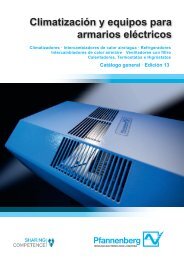
1 Introduction1 IntroductionControl systems which perform safety functions are employed in order for machines tobe designed safely and thereby to satisfy the requirements of the Machinery Directive,2006/42/EC. For this purpose, the safety functions required for risk reduction are defined aspart of the risk assessment conducted during design of the machine and then implementedby means of a suitable control system. <strong>The</strong> safety-related parts of machine controls can beimplemented in accordance with EN ISO 13849-1. Included in the requirements of this standardis the necessity for the machine design engineer to calculate the probability of a dangerousfailure per hour (PFH) in order to determine the Performance Level (PL). <strong>The</strong> PerformanceLevel is dependent upon the control system's structure (Category), as well as thesystematic requirements.For this purpose, the IFA provides the <strong>SISTEMA</strong> software tool (the German acronymstands for "safety of controls on machines”), which can be downloaded free of charge fromwww.dguv.de/ifa, Webcode e34183.Before beginning the calculations, the machine design engineer must produce a safetyrelatedblock diagram for each safety function from the circuit diagram. <strong>The</strong> safety-relatedblock diagram must show the implementation of the safety function in functional channels(including redundant channels, where present) and testing components, also where present.<strong>The</strong> <strong>SISTEMA</strong> <strong>Cookbook</strong> 1 addresses this unfamiliar and difficult abstraction step (Figure 1)and the subsequent step, that of transferring the blocks to <strong>SISTEMA</strong> and entering their parameters.<strong>SISTEMA</strong> <strong>Cookbook</strong> (Version 1.0) - 4 -
1 IntroductionFigure 1:Flow chart, from the safety function to the Performance Level; the four steps with grey background aredescribed in detail in these instructions.<strong>SISTEMA</strong> <strong>Cookbook</strong> (Version 1.0) - 5 -
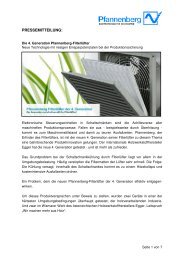
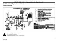
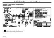
2 Schematic circuit diagram showing functional and test channels2 Schematic circuit diagram showing functional and test channels2.1 Creating the schematic circuit diagramIn order for the probability of failure of a safety function to be calculated at a later stage, itmust be known which components are employed in the safety function and which are not.A precise definition of the safety function (see BGIA Report 2/2008, Chapter 5) is thereforeindispensable for the subsequent steps. <strong>The</strong> schematic circuit diagram showing the relevantcomponents is produced for each safety function. <strong>The</strong> relevant components include allthose of which the failure may impair execution of the safety function in a functional channel(redundant structures possess two functional channels). <strong>The</strong>y also include all test facilitiesresponsible for detecting such dangerous failures and bringing about a safe state. A schematiccircuit diagram shows for example the electrical circuitry of position switches, programmablelogic controllers (PLCs) and contactors, and the flow of current from the sensor,via signal processing, to the actuator.Example 1 (Figure 2) shows an implementation of the safety function for "opening of themovable guard initiates the safe torque off (STO) safety function". All other componentswhich are purely functional and have no influence upon the safety function have alreadybeen omitted.Figure 2:Schematic circuit diagram showing relevant components (Example 1); see BGIA Report 2/2008e,Chapter 8.2.18<strong>SISTEMA</strong> <strong>Cookbook</strong> (Version 1.0) - 6 -
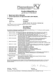
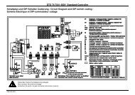
2 Schematic circuit diagram showing functional and test channels2.2 Entering the function and test channels<strong>The</strong> functional channels are first marked on the schematic circuit diagram. It has beenfound effective in practice to "work backwards", i.e. to begin at the actuator end and followthe channel back to the sensor. This yields the signal paths from the triggering event to theresponse of the safety function (Figure 3).Figure 3:Schematic circuit diagram with two redundant functional channels, B1-Q2 and B2-K1-Q1 (Example 1)Where circuits employ a test channel with a dedicated disconnecting device (Category 2),this test channel is also marked on the schematic circuit diagram. Figure 4 shows the exampleof a protective device fitted at the intake of a roller; when the device is tripped, the motoris stopped within 1/3 of a rotation. In this example, the angle of rotation required for the motorto come to a stop is tested regularly by manual actuation of the protective device.<strong>SISTEMA</strong> <strong>Cookbook</strong> (Version 1.0) - 7 -
2 Schematic circuit diagram showing functional and test channelsFigure 4:Example 2 with marked functional channel B0 – T1 – G1 and test channel with dedicated disconnectingdevice G2 – K1 – Q1Chapter 3 explains how the schematic circuit diagram is transformed into a safety-relatedblock diagram.<strong>SISTEMA</strong> <strong>Cookbook</strong> (Version 1.0) - 8 -
3 From the schematic circuit diagram to the safety-related block diagram3 From the schematic circuit diagram to the safety-related blockdiagramIn the next step, the schematic circuit diagram is transformed for each safety function into thelogical representation of the safety-related block diagram. In the course of the transformation,the components of the schematic circuit diagram are assigned to "subsystems" with whichthe safety function is modelled in <strong>SISTEMA</strong>.In the presentation as a safety-related block diagram the logical interrelationships are relevantrather than the physical connections between the components. Each component withina safety function is a constituent part of a certain structure. This structure is termed a "Category"in EN ISO 13849-1, and grouped within <strong>SISTEMA</strong> as a subsystem. <strong>The</strong> sequences ofsubsystems with their corresponding Categories are represented by a safety function in theform of a safety-related block diagram. <strong>The</strong> sequence of the subsystems has no bearingupon subsequent calculation of the probability of failure.3.1 Categories to EN ISO 13849-1<strong>The</strong> Categories to EN ISO 13849-1, their characterizing features and their typical representationare shown in Table 1.Table 1: Features and representation of the CategoriesStructureSingle-channelCategory to EN ISO 13849-1 andparticular featuresCategory B (basic category)Typical representation in thesafety-related block diagramSingle-channelCategory 1 (use of well-tried components)Single-channel,testedTwo-channel,with fault detectionCategory 2 (component faults in thefunctional channel (X3) are detectedby fault detection via the test channel(X4, X5); the safe state isbrought about)Note: the functional and test channelmay comprise one or morecomponent(s).Category 3 (single-fault tolerance byredundancy, testing)Note: Each channel may compriseone or more component(s).<strong>SISTEMA</strong> <strong>Cookbook</strong> (Version 1.0) - 9 -
3 From the schematic circuit diagram to the safety-related block diagramStructure Category to EN ISO 13849-1 and Typical representation in theparticular featuressafety-related block diagramTwo-channel,with fault detectionCategory 4 (as for Category 3, butalso robust against the accumulationof two undetected faults)Note: Each channel may comprise one ormore component(s).Encapsulated subsystems constitute a particular case. Encapsulated subsystems are componentsfor which the manufacturer himself states the PL, PFH and Category (e.g. safetyPLC, safety modules); see Table 2.Table 2: Encapsulated subsystemsStructureDifferent internalstructures possibleCategory to EN ISO 13849-1 andparticular featuresPL, PFH and Category are stated bythe manufacturerTypical representation in thesafety-related block diagramNote: Component arrangements other than these do not comply with the designated architecturesof EN ISO 13849-1 and cannot be analysed by <strong>SISTEMA</strong>.3.2 Structural analysis and explanationsIn the structural analysis, the components in the schematic circuit diagram are transferred toa safety-related block diagram, and the Category is determined by means of the characteristicsof redundancy, testing, and the use of well-tried components.Note: This section is only concerned with determining the structure. Additional requirementsbeyond this apply to all Categories: for example, components must be designed,fabricated, selected, assembled and combined in compliance with the relevant standardsin such a way that they are able to withstand the anticipated ambient conditions.Essential safety principles must be applied. In Categories 1, 2, 3 and 4, safetyprinciples which are well-tried must also be applied. Information on these aspects canbe found in EN ISO 13849-2. Quantitative requirements the observance of which ischecked by <strong>SISTEMA</strong> also apply to the Categories.<strong>The</strong> procedure described here is geared to the application of EN ISO 13849-1 and its "designatedarchitectures" for the Categories. If modelling to one of the categories is not possible,even when additional components or channels are omitted, the simplified method describedin the standard cannot be applied. In this case, the probability of failure must be verifiedwith recourse to other methods, such as Markov modelling, as described in EN 61508-6,Annex B.<strong>SISTEMA</strong> <strong>Cookbook</strong> (Version 1.0)- 10 -
3 From the schematic circuit diagram to the safety-related block diagramProcedure for structural analysis:<strong>The</strong> starting-point for the structural analysis is the schematic circuit diagram on which thefunction and test channels are marked. <strong>The</strong> procedure is shown schematically in Annex E.Figure 5 contains the same procedure, together with its application to Examples 1 and 2shown in Chapter 2.Step 1: Formation of a sequence of the components in a functional channelAll components along the first functional channel (that with the fewest components) are writtenas blocks from left to right (from the sensor to the actuator).Step 2: Considering the first blockEach individual block of the first functional channel is now assigned in turn to subsystems ofthe relevant Category, according to the characteristic features of the Categories.Step 3: Does the component manufacturer state the PL and PFH (and Category)?An encapsulated subsystem can be recognized as such by the fact that it is already characterizedby the manufacturer by a PL (or SIL in accordance with IEC standards), PFH andCategory (internal structure). <strong>The</strong> internal structure of the encapsulated subsystem need notbe deconstructed further.Note: If a Category 3 or 4 encapsulated subsystem occupies in both redundant functionalchannels, both functional channels pass through it.Step 4: Can all component faults be excluded?All assumed faults for the component in the block under analysis are considered in turn. Forthis purpose, the annex of EN ISO 13849-2 contains the fault models of a number of componentsused in machine controls. Owing to justified fault exclusions, certain component faultscan be discounted. For each fault case, it must be considered whether the intended safetyrelatedfunctionality of the component is retained (harmless fault) or fails (dangerous fault).A dangerous fault exists for example for contactor Q2 in Example 1 (Figure 3) when thesafety door is opened but Q2 fails to drop out because its contacts have welded.Should no dangerous faults whatsoever need to be assumed for the component, no valueexists for calculation of the PFH of the safety function. It need not be considered in thesafety-related block diagram. Further presentation of the safety function can however beconstructive, since it may be conducive to an understanding of it. In this case, the block istreated as an encapsulated subsystem ("fault exclusion" is then subsequently ticked in<strong>SISTEMA</strong>, and further entries are not required).Step 5: Is the safety function retained in the event of component faults?<strong>The</strong> dangerous faults to be assumed for the component in the block under analysis aredetermined in Step 4. <strong>The</strong>ir effects upon the safety function are now considered.<strong>SISTEMA</strong> <strong>Cookbook</strong> (Version 1.0) - 11 -
3 From the schematic circuit diagram to the safety-related block diagramFigure 5: Flow chart of structural analysis with reference to the examples from Chapter 2: SF = safety function<strong>SISTEMA</strong> <strong>Cookbook</strong> (Version 1.0) - 12 -
3 From the schematic circuit diagram to the safety-related block diagramStep 5a: Adding the redundant functional channel of the block(s)If the safety function is maintained by one or more redundant components in the event of afault in the block under analysis (i.e. a second functional channel is present), these componentsare presented as blocks in a second functional channel (refer to the example in Table1: Categories 3 and 4).In Example 1 (Figure 3), this applies to both B1 and Q2. <strong>The</strong> redundant functional channelB2-K1-Q1 is therefore added to both blocks.Note: <strong>The</strong> components of the redundant functional channel are thus used several times.This is a result of the phased procedure and should not be a hindrance at this stage.Blocks of which multiple instances exist are grouped together again in Step 8.If redundant components have been entered, a major basic criterion for Categories 3 and 4has been met. A single fault in a component of the first or second functional channel mustnot result in loss of the safety function (single-fault tolerance).Note: In addition, Category 3 requires that, wherever reasonably possible, individual faultsin components within the two functional channels should be detected.Step 5b: Is the safety function retained in the event of an accumulation of undetectedfaults?For the block under analysis here and its redundant functional channel, single-fault tolerancehas been identified up to this point and Category 3 is satisfied. Are the criteria for Category 4also met? For this purpose, the behaviour in the event of undetected faults occurring must bestudied. If the safety function is retained in the event of an accumulation of two undetectedfaults, the subsystem satisfies Category 4. If the safety function is not retained at the secondundetected fault, the subsystem satisfies Category 3.In Example 1 (Figure 3), PLC K1 could actuate outputs O1.0 and O1.1 continuously in theevent of a fault. Q1 would be continually energized in this case. Even if the PLC were ableto detect this fault by reading back of the monitoring contacts, it would not be able to bringabout the safe state. Should a second fault then cause the contacts of Q2 to weld, the motorwould continue to run even with the protective equipment open; the safety function hasfailed, and Category 4 is not met.Note: In Category 4, single-fault tolerance must be satisfied and the discrete fault in a componentin the first or second functional channel must be detected at or before the nextdemand upon the safety function. If detection in this way is not possible, an accumulationof two undetected faults must not lead to loss of the safety function.Step 6: Are component faults detected?At this point, it is clear that there is no redundancy and that consequently neither Category 3nor Category 4 is met. If failure of a block in a test channel is detected by a test channel andthe safe state is brought about, the subsystem satisfies Category 2.In Example 2 (Figure 4), tripping of B0 causes controlled stopping of the motor by T1/G1within 1/3 of a rotation. Testing is in response to a demand by K1 prompted by manual actuationof B0 and measurement of the stopping angle by K1/G2. In the event of a fault, the safestate is brought about via Q1. <strong>The</strong> test detects faults in B0 and T1/G1. <strong>The</strong> test channel G2-K1-Q1 thus detects faults in B0 and T1/G1 and brings about the safe state; Category 2 isthus met.Note: Reasonable fault detection is also a requirement for Categories 3 and 4. Conversely,Category 2 subsystems lack a redundant functional channel.<strong>SISTEMA</strong> <strong>Cookbook</strong> (Version 1.0) - 13 -
3 From the schematic circuit diagram to the safety-related block diagramStep 6a: Adding the test channel of the block<strong>The</strong> components of the test channel which detect failure of the block and bring about the safestate are presented in the safety-related block diagram as test blocks as shown in Table 1(Category 2)If components are entered in the test channel, a major basic criterion for Category 2 is met:the safety function must be tested at suitable intervals. This causes the loss of the safetyfunction to be detected and a safe state to be brought about by an independent disconnectingdevice. A further important requirement for Category 2 is the test frequency (see BGIAReport 2/2008e, Section 6.25). However this is not relevant to the structural analysis.Step 7: Is the component "well-tried"?Redundancy or testing was not found in the example. Only Category 1 or Category B aretherefore possible. Should the component in the block under analysis be a "well-tried" componentto EN ISO 13849, the block is presented as part of a Category 1 subsystem. A list ofwell-tried components can be found in EN ISO 13849-2. If not, the block is part of a CategoryB subsystem.Step 8: Have all blocks been analysed?If further blocks still await analysis following assignment of the block to a subsystem, the procedureon the diagram is repeated with the next block, beginning at Step 2a. <strong>The</strong> procedureotherwise continues at Step 9.Step 9: Grouping blocks of the same categorySubsystems of the same category can be merged by the grouping of components of identicalchannels (see BGIA Report 2/2008, Figure 6.14). Each component occurs only once within achannel; duplicates can be removed. <strong>The</strong> same component clearly cannot be used simultaneouslyin two redundant functional channels. In Category 2, only components which sharethe same test channel can be grouped in a functional channel.Since <strong>SISTEMA</strong> limits MTTF d values of each channel within the subsystems (capping),grouping may result in a lower probability of a dangerous failure per hour being calculated.<strong>The</strong> lower probability of failure (PFH) is an advantage. A disadvantage however is that thegrouped representation often makes it more difficult to follow the logical sequence of signalprocessing.<strong>The</strong> examples in Chapter 2 yield the safety-related block diagrams in Figure 5a:Figure 5a: Result of the structural analysis for the examples from Chapter 2<strong>The</strong> safety function is now presented logically on the safety-related block diagram. In thenext chapter, the probability of failure (PFH) is calculated with the aid of <strong>SISTEMA</strong>.<strong>SISTEMA</strong> <strong>Cookbook</strong> (Version 1.0) - 14 -
4 Transfer to <strong>SISTEMA</strong>4 Transfer to <strong>SISTEMA</strong><strong>The</strong> <strong>SISTEMA</strong> software tool employs multiple hierarchical levels (Figure 6). <strong>The</strong> individuallevels are explained in Table 3.Figure 6: Hierarchical levels in <strong>SISTEMA</strong>Table 3: Description of the hierarchical levels in <strong>SISTEMA</strong>Name Description ExamplesProjectSafety functionSubsystemSummary of safety functions, forexample on a machine or part ofa machine, or at a hazard pointSafety-oriented response to atriggering eventa) Group of blocks within a rigidstructure (Category)Door to the working area on lathe XYSafe operating stop when a safetydoor is openeda) Category 3 subsystemb) Safety component withstatement by the manufacturerof the PL, PFH and Category(encapsulated subsystem)b) Safety PLC<strong>SISTEMA</strong> <strong>Cookbook</strong> (Version 1.0) - 15 -
4 Transfer to <strong>SISTEMA</strong>Name Description ExamplesChannelConnection of blocks in series;<strong>SISTEMA</strong> creates either one ortwo functional channels, dependingupon the selectedCategory.Functional channel 1Test channelConnection of blocks in seriesfor the test function; <strong>SISTEMA</strong>only creates a test channel forCategory 2.Functional channel 2Functional channel 1BlockElementComponent in the function ortest channelA block contains one or moreelements. A B 10d value (see AnnexB) can only be entered forelements.Test channelSafety PLCContactors, position switches, electromechanicalcomponents, all componentswith a manufacturer'sB 10d -valueAll steps required for creation of a <strong>SISTEMA</strong> project and for analysis are explained below.<strong>The</strong> entries relating to documentation have no influence upon the analysis. This aspect willnot be considered further.Note: It is advisable to select the order of entries such that the tabs in the working area areworked through from left to right, and the hierarchy levels (tree view in the navigationwindow) from top to bottom.4.1 Creating a projectAll safety functions of a machine or sub-machine can be grouped within a project (Figure 7).After creating a new project with "New" (1.), enter a name in the "Project name" dialog (3.).<strong>The</strong> name then also appears in the navigation window after the abbreviation PR (2.).1.2.3.<strong>SISTEMA</strong> <strong>Cookbook</strong> (Version 1.0) - 16 -Figure 7
4 Transfer to <strong>SISTEMA</strong>4.2 Creating safety functionsCreate the required safety functions with "New" (3.) on the "Safety function" tab (2.)(Figure 8). <strong>The</strong> "Name of safety function" also appears in the navigation window, after theabbreviation SF (see Figure 9; 1.).1. 2.3.Figure 84.3 Setting the PLr<strong>The</strong> required Performance Level PL r is determined individually for each safety function (1.)(Figure 9). For this purpose, use the risk graph (3.) under "Safety function – PLr" (2.), orenter the PL r is directly, for instance when it is specified by a machine-specific standard.1. 2.3.Figure 94.4 Adding subsystems<strong>The</strong> subsystems determined in the safety-related block diagram are created. Add a subsystemwith "New" (3.) under the safety function (1.) on the "Subsystems" tab (2.) (Figure 10).<strong>SISTEMA</strong> <strong>Cookbook</strong> (Version 1.0) - 17 -
4 Transfer to <strong>SISTEMA</strong>1. 2.3.Figure 104.5 Encapsulated subsystemsManufacturers' data on the PL, PFH and Category are available for encapsulated systems.Enter them (4.) directly below the subsystem (1.) in the "PL" tab (2.) after selecting "EnterPL / PFH directly" (3.) (Figure 11). <strong>The</strong> Category can be entered in the next tab, "Category".Since the PL and PFH are available for this subsystem, it is not necessary to enter the Categoryfor calculation of the PFH of the safety function as a whole.Note: If the box (4.) is checked, the PL and PFH are calculated from each other by meansof mean values.Fault exclusion:In encapsulated systems in which all hazardous component faults are excluded, check the"Failure exclusion" box ( PFH=0).2.1.3. 4.Figure 114.6 Subsystems as groups of blocks within a rigid structure (Category)In the subsystem (1.), select "Determine PL / PFH from Category, MTTF d and DC avg " under"PL" (2.) (Figure 12).1.3.2.<strong>The</strong>n:Figure 12a) In the subsystem (1.) under "Category" (2.) (Figure 13), select the relevant Category andevaluate the "Requirements of the Category".<strong>SISTEMA</strong> <strong>Cookbook</strong> (Version 1.0) - 18 -
4 Transfer to <strong>SISTEMA</strong>2.1.b) Enter the MTTF d value directly in the subsystem (1.) under "MTTF d " (2.), or select"Determine MTTF d -value from blocks" (3.) (Figure 14).Figure 131.3.2.Figure 14c) Enter the DC avg value directly in the subsystem (1.) under "DC avg " (2.), or select "DetermineDC avg -value from blocks" (3.) (Figure 15).2.1.3.Figure 15d) For each two-channel subsystem, faults must be considered which would cause bothchannels to fail for the same reason (CCF). Of these, Category 2 (functional channel andtest channel) and Categories 3 and 4 (two functional channels in each case) are affected.Entry is made in the subsystem (1.) under "CCF" (2.) by selection of the measures to betaken (Figure 16). At least 65 points must be reached. <strong>The</strong> number of points reached canbe entered directly or compiled by a library of measures (3. and 4.).1.2.3.4.<strong>SISTEMA</strong> <strong>Cookbook</strong> (Version 1.0) - 19 -Figure 16
4 Transfer to <strong>SISTEMA</strong>4.6.1 Entering blocksOnce the subsystems have been formed, further specification is necessary (exception: 4.5Encapsulated subsystems). When the Category of a subsystem is selected, <strong>SISTEMA</strong>creates the relevant channels (CH). Under "Channel", the blocks (BL ) are added correspondingto the individual components of a channel. If no further subdivision of the blocks isrequired, the procedure can continue with 4.6.3. If a block is to be further subdivided intoelements (always necessary with components for which the B 10d is stated), the following settingsare required:a) In block (1.) under "MTTF d " (2.), select "Determine MTTF d -value from elements" (3.)(Figure 17).1.3.2.Figure 17b) In block (1.) under "DC" (2.), select "Determine DC-value from elements" (3.) (Figure 18).2.1.3.Figure 184.6.2 Entering elementsIf a block is to be divided into elements (EL), create elements in the block (1.) under"Elements" (2.) with "New" (3.) (Figure 19).<strong>SISTEMA</strong> <strong>Cookbook</strong> (Version 1.0) - 20 -
4 Transfer to <strong>SISTEMA</strong>1.2.3.Figure 19At element level (1.), calculation is necessary with consideration for the B10 d value and thenumber of operations n op , for example in order to determine the MTTF d (2.) of electromechanicaland pneumatic components (Figure 20). Select "Determine MTTF d -value fromB 10d -Value" (3.) and "Calculate nop " (4.) in order to enter the required values (5.).2.1.3.4.5.Figure 204.6.3 Entering safety-related data<strong>The</strong> safety-related data required for calculation of the PFH include the applicable componentquality (MTTF d , B 10d ), the number of operations of electromechanical and pneumatic components(n op ) and the diagnostic coverage (DC).4.6.3.1 MTTF d /B 10dEnter at block or element level (1.) on the "MTTF d " tab (2.) (Figure 21).<strong>SISTEMA</strong> <strong>Cookbook</strong> (Version 1.0) - 21 -
4 Transfer to <strong>SISTEMA</strong>Figure 21<strong>The</strong> safety-related parameters of the components can be determined from any of thefollowing:a) Manufacturers' datab) Established collections of data (for sources, see EN ISO 13849-1, Annex D)c) EN ISO 13849-1, Annex C; stored in <strong>SISTEMA</strong> under "Typical component values" (3.).If all dangerous component faults can be excluded, a fault exclusion can also be selectedwhen "Enter MTTF d -value directly" is selected.4.6.3.2 DCFor Category 2 and higher, fault-detection measures for the components are required. Inthe block or element (1.), a percentage is entered on the "DC" tab (2.) for each component todescribe the diagnostic coverage of fault detection. Selection of "DC-rating by choosingmeasures" enables the DC tables in EN ISO 13849-1, Annex E to be accessed via "Library"(3.). <strong>The</strong> values can be accepted as-is or used for guidance.Where the standard proposes aband of possible DC values, a concrete value within this band can be selected (Figure 22).2.1.3.Figure 22<strong>SISTEMA</strong> <strong>Cookbook</strong> (Version 1.0) - 22 -
4 Transfer to <strong>SISTEMA</strong>4.7 Objective attained?Check for error messages (red cross) in the message window (centre, below). If none arepresent, the PFH can be calculated (Figure 23).Figure 23<strong>The</strong> result of the calculation is indicated at the bottom left for the selected safety functionand the corresponding subsystems, blocks and elements (Figure 24). <strong>The</strong> (attained) PL ofthe safety function must at least equal the (required) PL r . If the attained PL is insufficient,components with a higher MTTF d or a higher B 10d value must be employed, the fault detection(DC) must be improved, or subsystems of other Categories must be implemented.Figure 24<strong>SISTEMA</strong> <strong>Cookbook</strong> (Version 1.0) - 23 -
Annex AConcepts and abbreviationsAnnex A: Concepts and abbreviationsDefinition of key concepts referred to in a similar way in Annex B of EN ISO 13849-1:ConceptsSafety function (SF)Schematic circuit diagramSafety-related blockdiagramComponentsSubsystem (SB)Encapsulated subsystemFunctional channelFunction signalRedundant functionblockNon-redundant functionblockTest channelTesting disconnectionsignalTest blockClosed-circuit currentprincipleDefinitionSafety-oriented response to a triggering event (demand upon thesafety function). In redundant systems, the safety function is executedin multiple and independent ways. <strong>The</strong> PL describes thereliability of its execution.Excerpt from the wiring diagram or function circuit diagram whichindicates the technical (hardware) interconnections between thesafety-related parts of the control system.Presentation of the logical connections between the componentsfrom which the functional and test channels can be seen.Safety-related hardware units, parts of the control systemLargest unit of components which executes the safety functionfully or in sections. A subsystem possesses a continuous structureand is described by a Category.Safety component for which the manufacturer already states thePL, PFH and Category. <strong>The</strong> internal structure need not thereforebe considered more closely.Hardware units connected in series; chains of components whichexecute the entire safety function from the sensor to the actuator.Redundant subsystems possess (at least) two independent functionalchannels.Signal that passes the demand for the safety function on along afunctional channel from the sensor to the actuator, where forexample it leads to disconnection.Hardware unit connected in parallel; component in a section of aredundant functional channel; part of a functional channel inCategory 3 or 4 subsystems.Component in a section of a non-redundant functional channel;part of a functional channel in Category B, 1 or 2 subsystems.Chain of components which transmits a "Testing" disconnectionsignal (not to be confused with the signal path over which testsignals are exchanged between the testing and tested blocks forthe detection of a dangerous failure).Transmits the result of a test which has detected a dangerousfailure of a function block, from a test block to a function blockfurther on or to an additional disconnecting block, with the resultthat the safety function is successfully completed or a safe stateis brought about.Hardware unit for diagnostics:Component that tests one or more function blocks and generatesa "Testing" disconnection signal when it detects a dangerousfailure in them; ora transmitting or disabling block in the test channelInterruption of a circuit leads to the safe state.<strong>SISTEMA</strong> <strong>Cookbook</strong> (Version 1.0) - 24 -
Annex B Abbreviations from EN ISO 13849 1Annex B: Abbreviations from EN ISO 13849-1AbbreviationUnit Name CommentSRP/CS - Safety-Related Part of a ControlSystemMTTF d Year, a Mean Time To dangerous Failure Component qualityDC % Diagnostic Coverage Test quality (block, element)DC avg % Average Diagnostic Coverage Test quality (subsystem)CCF - Common Cause Failure Simultaneous failure ofredundant channelsPFH 1/h Probability of a dangerous Failureper HourProbability of failurePL - Performance Level Actual value of the functionalsafetyPL r - Required Performance Level Specified value of the functionalsafetyCat. - CategoryT M Year, a Mission Time Service lifeB 10d Cycles Number of cycles until 10% of thecomponents fail dangerouslyT 10d Year, a Mean Time until 10% of the componentsfail dangerouslyn op Cycles/a number of operations(average, per year)Component quality (wearingcomponent)Permissible operating time(wearing component)Operating frequency<strong>SISTEMA</strong> <strong>Cookbook</strong> (Version 1.0) - 25 -
Annex CModel form for user's applicationsAnnex C: Model form for user's applicationsDefinition of the safety function:Triggering event:______________________________________________________________________________________________________________________________________Response:______________________________________________________________________________________________________________________________________Safe state:______________________________________________________________________________________________________________________________________Schematic circuit diagram with entries for functional and test channels:In the annexSafety-related block diagram of the first functional channel, where applicable with theaddition of components in the second functional channel or in the test channel:Final safety-related block diagram, where applicable following the grouping of subsystems ofthe same Category:<strong>SISTEMA</strong> <strong>Cookbook</strong> (Version 1.0) - 26 -
Annex DSchematic tableAnnex D: Schematic table<strong>The</strong> schematic table is an alternative method of structure analysis in accordance withFigure 5. All components shown on the schematic circuit diagram are entered in a table inaccordance with the method described in Section 3. Table 4 shows the possible combinationsand the resulting structure (possible Category) and presentation in the safety-relatedblock diagram; Table 5 has been completed for the example in Section 3, and Table 6 providesan empty form for the user's examples.Table 4: Formalized schematic table for structure analysis in accordance with Section 3 (the stepsstated in Section 3 are entered in red)Components in thefirst functional channelIs the Categorystated by the componentmanufacturer(3)?Redundant component(s)(4)Component(s) in thetest channel (faultdetection and disconnection)(5)(1) X1 (2) X2(2a) X3 (2a) X4 (2a)YesX5 (, X6) (4a)X7 (, X8) (5a)Possible CategoryB to 4EncapsulatedsubsystemB or 1 (6) 3 or 4 (4b) 2Block presentationIt can be helpful during the structure analysis to imagine Steps 3, 4 and 5 as follows: whathappens when the component is hit with a "test hammer", i.e. a component fault is induced?(3) Does the internal structure maintain the (safety) function?(4) Is the SF retained owing to redundant design of the SF involving other components?(5) Is the component fault detected in time and a safe state brought about?<strong>SISTEMA</strong> <strong>Cookbook</strong> (Version 1.0)- 27 -
Annex DSchematic tableTable 5: Table completed for the example in Section 3Components in the firstfunctional channelIs the Category statedby the componentmanufacturer?Redundant component(s)B1B2Q2K1, Q1Component(s) in thetest channel (fault detectionand disconnection)Block diagram(summary): (8)Possible Category 3 or 4 3 or 4Block presentationB1Q2B2 K1 Q1Table 6: Form for user's examplesComponents in thefirst functional channelIs the Categorystated by the componentmanufacturer(3)?Redundant component(s)(4)Component(s) in thetest channel (faultdetection and disconnection)(5)Possible CategoryBlock presentation<strong>SISTEMA</strong> <strong>Cookbook</strong> (Version 1.0) - 28 -
Annex EFlow chart for structure analysis (without example)Annex E: Flow chart for structure analysis (without example)<strong>SISTEMA</strong> <strong>Cookbook</strong> (Version 1.0) - 29 -