GAS BURNERS OVEN ZEPHYR - System Control Engineering
GAS BURNERS OVEN ZEPHYR - System Control Engineering
GAS BURNERS OVEN ZEPHYR - System Control Engineering

Create successful ePaper yourself
Turn your PDF publications into a flip-book with our unique Google optimized e-Paper software.
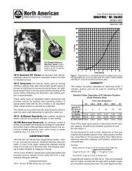
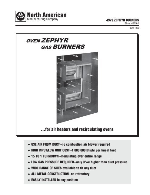
Flow <strong>Control</strong> Business Group4979 <strong>ZEPHYR</strong> <strong>BURNERS</strong>Sheet 4979-1June 1999<strong>OVEN</strong> <strong>ZEPHYR</strong><strong>GAS</strong> <strong>BURNERS</strong>...for air heaters and recirculating ovensl USE AIR FROM DUCT--no combustion air blower requiredl HIGH INPUT/LOW UNIT COST--1 000 000 Btu/hr per lineal footl 15 TO 1 TURNDOWN--modulating over entire rangel LOW <strong>GAS</strong> PRESSURE REQUIRED--only 3"wc higher than duct pressurel WIDE RANGE OF SIZES available to fit any ductl ALL METAL CONSTRUCTION--no refractoryl EASILY INSTALLED in any position
NORTH AMERICAN Mfg. Co. Sheet 4979-1, 6-99Cleveland, OH 44105-5600 USA Page 4INSTRUCTIONS(Burner with Gas Pilot)1. Adjust the profile plates until a differential pressure of 1.0"wccan be read across the duct air pressure taps on the feed endplate(FEP). The burner will operate with any duct differentialpressure between 0.30 and 1.50"wc. Air flow at the profile platemust be of uniform velocity and not spinning.2. Ignite the gas pilot and adjust the gas flow (usually by screwdriveradjustment in the gas cock) until flame is about 6" longand a good flame detector signal is obtained.3. Adjust the main gas control valve linkage for desired valve travel.4. Open the 1518 or 1519 Valve. With the control valve wide open,use a metering orifice and manometer to adjust the gas pressureregulator to obtain 1 000 000 Btu/hr for each lineal foot ofburner. The flame should then be mostly blue with some yellowtinges and about 24" long with 1"wc duct differential pressure;30" long with 0.5"wc.5. Adjust and test all burner safety devices--manual reset fuelshutoff valve, purge timer, low fire start, air flow switch, flamesafety relay, high and low gas pressure switches, over-temperaturecontrol, block and vent valves, etc.DIMENSIONSinches612" for -12 or -12-B6" for -6 or -6-B-12 (wt. 21 lb)or -6 (wt. 11 lb)10 9 /1612 9 /16-12-B (wt. 22 lb)or -6-B (wt. 12 lb)2 1 /2 fpt gas conn.6 (-12, -12-B)3 (-6, -6-B)hole must be positionedso it faces upstreamLI or LO(wt. 20 lb)94-5257-1 Pilot Assembly3/8 tubing or 1 /8 pipeFEPFeed Endplate(left)(wt. 3 lb)10 9 /166 1 /4FEP1/8 fptduct pressuretaps7/8 boreUV orflame rodlocationIgniter10 9 /166 1 /4SEP7/8 boreUV orflame rodlocationhole forpilot or igniterSEPSupport Endplate(right)(wt. 3 lb)1 7 /162" fptgas conn.1 3 /43/4 fptpipesupport2 1 /82 1 /8DIMENSIONS SHOWN ARE SUBJECT TO CHANGE. PLEASE OBTAIN CERTIFIED PRINTS FROM NORTH AMERICAN MFG. CO.IF SPACE LIMITATIONS OR OTHER CONSIDERATIONS MAKE EXACT DIMENSION(S) CRITICAL.WARNING: Situations dangerous to personnel and property can develop from incorrect operation of combustion equipment.North American urges compliance with National Safety Standards and Insurance Underwriters recommendations, and care in operation.Printed in USANA699-4979-1