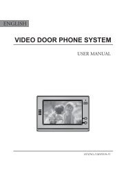
video door phone system - Schick Handel
video door phone system - Schick Handel
video door phone system - Schick Handel
- No tags were found...

Create successful ePaper yourself
Turn your PDF publications into a flip-book with our unique Google optimized e-Paper software.
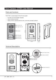
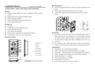
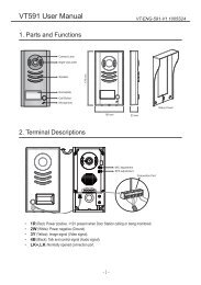
1. Parts and Functions1 23945678Dimensions: 160(H)×223(W)×25(D)1. LCD Touch Screen2. Loud Speaker3. TALK Button4. ( ) MENU Button5. ( ) MONITOR Button6. ( ) UNLOCK Button7. ( ) CALL Button8. Micro<strong>phone</strong>9. MESG Indicator2. Mounting and Installation1. Use the screws to fix the MountingBracket on the wall.(fitting accesoriesincludes a Bracket (Two 4X25 screwsare needed for fastening the MountingBracket), Special 4 core cables toconnect with Monitor)2. Wire the <strong>system</strong> correctly(see the laterconnection chapter) then hang theMonitor on the Mounting Bracket firmly.3. Test the <strong>system</strong> untill it works properly.-1-
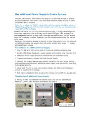
3. Standard System WiringTerminal Discriptions:●●●●●●●●1R Power positive. +12V present when Door Station calling or being monitored2W Power negative (GND)3Y Image signal (Video signal)4B Talk and control signal (Audio signal)It’s recommended to use RVVP 4x0.3mm2 Shielded Cable. And when distance is over30m, we suggest to use additional co-axle cable SYV- 75-3 (RG-59) connect 3Y and 2Wpin.4AC ~1R2W3Y4B* Note 2* Note 3JP-VDJP-LKBack ViewCN101DC-DC+* Note 1JS-VP1R2W3Y4BJS/VPJS-OS21R2W3Y4B1R2W3Y4BJS/APJS-OS14B2W+12RedWhiteYellowBlackRedWhiteYellowBlack321* Note 4LB1R2W3Y4B1R2W3Y4B●●●●●●●●Note 1: Plug the AC Adaptor to the AC power socket properly.Note 2: JP-VD is used for setting the <strong>video</strong> impedance. When there is only one Monitor,keep the jumper (which is already on JP-VD ). But when multi Monitors are installed, besure of taking away all JP-VD of Monitors except only the last Monitor.Note 3: P-LK is used for Lock selection, remove the jumper if use the Monitor power tosupply the Lock. Refer to the Out<strong>door</strong> station manual.Note 4: LB includes 3 wiring Terminals: ‘1’-Normally Opened Terminal, ‘2’- CommonTerminal, ‘3’- Normally Closed Terminal. If the Lock is activated when powering, connect itbetween ‘1’ and ‘2’ terminal; if the Lock is activated when power-off, connect it between ‘2’and ‘3’ terminal.-2-
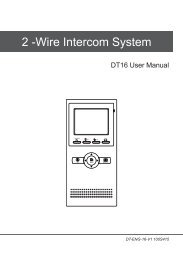
4. Extending Monitors or Auido PhonesAC ~AC ~Back ViewJP-VD Reserved!AC ~Back ViewJP-VD Removed!Back ViewJP-VD Removed!DCDC+CN101JP-VDDCDC+CN101JP-VDCN101JP-VDJP-LKJP-LKJP-LK1R2W3Y4BJS/VPJS-OS21R2W3Y4B1R2W3Y4BJS/VPJS-OS21R2W3Y4B1R2W3Y4BJS/VPJS-OS21R2W3Y4B3211R2W3Y4B4B2W+12JS/APJS-OS11R2W3Y4B4B2W+12JS/APJS-OS11R2W3Y4B4B2W+12JS/APJS-OS11R2W3Y4BLBJS-VPOTHER EXTENDEDMONITORSBlackYellowWhiteRedDC-DC+-3-Extending Audio Phone:Camera 1# Monitor 2# Monitor N# MonitorJP-LK4B2W+12Back View4JS-AP4 4DC-DC+CN101JP-VDJP-LKGX-3P1R2W3Y4BPS PSPSJS/VPJS-OS21R2W3Y4BINSIDE(90 Degree ROTATE)WhiteWhiteBlackBlack4B2W+12JS/APJS-OS11R2W3Y4BJP-VD Removed! JP-VD ReservedJP-VD Removed!RedRed
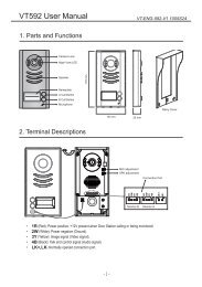
5. Extending 2 Out<strong>door</strong> StationsAC ~AC ~Back ViewJP-VD Removed!BlackJS-VPJP-VD Reserved!LBBack ViewJP-VD Removed!RedWhiteYellow1R2W3Y4B123321LBRedWhiteYellow1R2W3Y4BBlackJS-VPAC ~DCDC+1R2W3Y4B4B2W+12CN101 JS/VP JS/APJS-OS2 JS-OS1DCJP-VDDC+JP-LK1R1R2W2W3Y3Y4B4B1R4B2W2W3Y+124BCN101 JS/VP JS/APJS-OS2 JS-OS1OTHER EXTENDEDMONITORSBack ViewJS/VPJS-OS2JS/APJS-OS11R2W3Y4B1R2W3Y4BCN101JP-VD Removed!JP-VDDC-JP-VDDC+JP-LK1R1R2W2W3Y3Y4B4B1R4B2W2W3Y+124BJP-LK2# Monitor N# Monitor2# Camera 1# Monitor4 444PS PSPSJP-VD Removed! JP-VD Reserved1# CameraNOTE: When connect two Out<strong>door</strong> Stations, 1WAY/2WAY Mode shouldbe set to 2 on the FRIST Monitor. (Menu-setup-installation-1way/2way)-4-
6. Operation Instructions6.1 Basic Functions1. When visitor presses the Call Button on theOut<strong>door</strong> Station, the monitor rings, at thesame time, the screen displays the visitorimage, and MESG LED turns to red.2. Press TALK Button(or touch TALK iconon the screen), you can talk with the visitorfor 90 seconds. During talking state, pressIMG 162009/02/14TALK Button (or touch TALK )again to endthe conversation. If nobody answers the <strong>phone</strong>, the screen will be turned off automaticallyafter 30 seconds. If the <strong>system</strong> connects two or more Monitors, when any Monitor starts totalk, the other Monitors will be automatically shut off.3. When Monitor is standby, press MONITOR Button(or touch anywhere on the screen, thentouch monitor ), the screen will display the view of the Out<strong>door</strong> Station. During monitoring state,press TALK Button(or touch TALK ), you can talk with outside through the Out<strong>door</strong> Station,or press again to exit. However, monitoring state is limited to 30 seconds and will be shut offautomatically.4. Press UNLOCK Button(or touch ) to release the Electronic Latch during monitoring.5. During the monitoring, press the CALL Button(or touch rec ) to record the picture.6. During the monitoring, press MENU Button (or touch ) will show the creen settings.7. Touch the icon will hide all the icons on the screen, touch anywhere on the screen again,the icons will showed up.8. Touch the EXIT icon will close the screen and exit out.H o m e I n t e l l eg e n t S y s t e m6.2 Operation for Multi Out<strong>door</strong> Stations(if installed)1. All Monitors can monitor on each Out<strong>door</strong> Station in turn. Press MONITOR Button(or touchmonitor ) in standby, the image of the FIRST Door Station is displayed firstly. Press TALKButton(or touch TALK ) to talk, press MONITOR Button(or touch monitor )to switch to the nextOut<strong>door</strong> Station etc.2. Note that the 1WAY/2WAY Mode should be set to 2 in the SETUP --> INSTALLATIONsubmenu.-5-10:3003TALKEXITrec
6.3 Intercom function(available when Multi Monitors installed)1. Intercom can be initiated by any Monitor.Press CALL Button on one Monitor, theother Monitors will ring, and press CALLButton again to redial. If TALK Button ispressed on any other Monitor, intercomtalking is started.2. During intercom, press TALK Button tocancel(or touch EXIT ), or it will exitautomatically after 30 seconds.RedialEXITH o m e I n t e l l eg e n t S y s t e m3. Intercom function is prior to monitor function, but calling function is always the first.6.4 Image and Volume adjustments1. During monitoring or talking, press icon,ADJUST MENU will be displayed.2. Touch the item to be adjusted(or use the/ Buttons to switch up and down toselect), the selected item will be displayed inred color.3. To change the value of the current item,touch the / icons(or pressButton) to increase or decrease.4. Note: Total 4 SCREEN modes can beselected in sequence: NORMAL, USER,SOFT and BRIGHT. Whenever you modifyBRIGHTNESS or COLOUR, SCENE itemwill be set to USER mode automatically.5. RATIO can be shifted from 16:9 to 4:3.IMG 162009/02/1410:30H o m e I n t e l l eg e n t S y s t e mSCREEN -- SOTFRATIO -- 16:9BRIGHTNESS -- 4COLOR -- 4TALK VOL -- 6EXITH o m e I n t e l l eg e n t S y s t e m03TALKEXITrec6. The BRIGHTNESS and COLOR item is for the image quality setting, adjust the value to getthe best image you like.7. The TALK VOL item is for talking volume adjust.8. Press MONITOR or touch EXIT item to exit out the setting, Note that all the modifications willbe done immediately after the operation.-6-
6.5 Basic Setup Instructions1. During standby state, press the MENUButton(or touch the screen) to display MAINMENU.2. Press the / Buttons to select theSETUP item, then press the MENU Buttonagain to enter. (or touch the setup icon toenter SETUP MENU)3. The OUTDOOR CALL and INTERCOMCALL item are for chord ring selection, theRING VOLUME item is for ring volumeadjustment. Press / Button(or touch/ ) to increase/decrease.4. If the AWAY SET item is turned on, theMonitor will record the image automaticallyin 2 seconds after the visitor pressed theCALL Button on the Out<strong>door</strong> station.5. The INSTALLATION...item is for advancesettings. a password will be asked beforeenter the setting. The defoult password is2008.6. Input the password by touching the digitalkeypad on the screen to enter.(or you canpress / Buttons to change thecurrent digit, and press Button to shift tothe next one)7. The 1WAY/2WAY should be set to 2 if 2Out<strong>door</strong> stations were to be installed.8. UNLOCK TIME will be adjusted according todifferent locks.9. INFORMATION will show the hardware/software version and voltage info. theADVANCED SET is reserved.-7-playmonitorintercomsetupexitH o m e I n t e l l eg e n t S y s t e mDOOR CALL -- 01INTERCOM CALL -- 05RING VOLUME -- 06INSTALLATION...AWAY SET -- OFFEXITH o m e I n t e l l eg e n t S y s t e mPassword:0* * *H o m e I n t e l l eg e n t S y s t e m1WAY/2WAY -- 1UNLOCK TIME -- 3DATE/TIME SET...ADVANCED SET...INFORMATIONEXITH o m e I n t e l l eg e n t S y s t e m12345*67890#
6.6 Operation for Picture Memory1. The picture can be recorded both manuallyand automatically. The image capacity isabove 120 pcs, and the oldest one will bereplaced if the memory is full.playmonitor2. Manually record: when the screen is turnedon, in monitoring or talking state, touch therec icon (or press the CALL Button) to savecurrent image.IMG 162009/02/14intercomsetupexitH o m e I n t e l l eg e n t S y s t e m3. Automatic record: enter the SETUP page and turn on the AWAY SET item. Then the MESGindicator LED will be flashing in Green color.4. Playback the pictures: During the standby,press MENU Button(or touch the screen)to enter the main menu, then touch playicon(or use the Buttons to select) to enterthe playback page. The latest picture will beshow. touch NEXT / LAST icon(or pressthe / ) to view forward / backward.Touch the DELE? icon, a 'DELETE?' hint willshow on the uper right of the screen, TouchDELETE?10:30H o m e I n t e l l eg e n t S y s t e mthe DELE? icon again to delete the current picture. Please note that the delete operation isirrepeatable.5. Date and Time setting: Enter the SETUP --> INSTALLATION --> DATE/TIME SET item, thesetting page will show as bellow. Touch thekeypad on the screen to input the numbers.Or you can input the number by the Buttons:Press the / Buttons to change thecurrent number(which indicated by a uparrow), press the Button to switch to thenext number. (if input by Buttons, it will saveand exit automatically after input all thenumbers. If input by the screen, touch the #icon to save and exit)TIME*1 1 : 3 5DATE 2 0 0 9 0 2 1 4: CANCEL #: OKH o m e I n t e l l eg e n t S y s t e m12345*NEXTLASTDELE?EXIT67890#-8-
7. Precautions●●●●●●●●●●All parts should be protected from violence vibration. And not allow beimpacting, knocking and dropping.For clean the Lens& Screen, using hands or wet cloth is forbidden.Please do the cleanness with soft cotton cloth, please do not use the organic orchemical clean impregnate. If necessary, please use a little pure water or dilutesoap water to clean the dust.Image distortion may occur if the <strong>video</strong> <strong>door</strong> <strong>phone</strong> is mounted too close tomagnetic field e. g. Microwaves, TV, computer etc.Please keep away the <strong>video</strong> <strong>door</strong> monitor from wet, high temperature, dust,and caustic and oxidation gas in order to avoid any unpredictable damage.8. Specifications●●Power supply for in<strong>door</strong> monitor: DC 15~18V (supplied by Adaptor)●●Power supply for Door Station: DC 10~12V (Supplied by In<strong>door</strong> Monitor)●●Audio Phone : DC 10~12V (Supplied by In<strong>door</strong> Monitor)●●Power consumption: Standby 0.5W; Working status 15W (for kits)●●Monitor screen: 7 Inch color TFT-LCD●●Display Resolutions: 1,440(R, G, B) x 234 pixels●●Video signal: 1Vp-p, 75Ω, CCIR standard●●Pictures saved: 127 PCS●●Connection mode: 4 wiring, polar●●Monitor time: 30 seconds●●Talking time: 90 seconds●●Dimensions: 160(H)×223(W)×25(D)-9-