Emergency stop module BD 5934 - Kolektor
Emergency stop module BD 5934 - Kolektor Emergency stop module BD 5934 - Kolektor
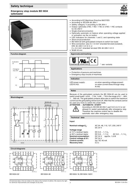
Safety techniqueEmergency stop module BD 5934safemaster0221547• According to EC Machines Directive 98/37/EG• According to IEC/EN 60 204-1• Safety category 4 according to EN 954-1• Output: optionally 2 NO, 1 NO / 1 NC or 3 NO / 1 NC contactsfor AC 250 V• Single-channel connection• Optionally automatic on feature when operating voltage appliedor activation via the on button• LED indicators for channels 1 and 2, and operating state• Short circuit protection• BD 5934.02 with gold-plated contacts to switch low loads• Wire connection: also 2 x 1,5 mm 2 stranded ferruled (isolated),DIN 46 228-1/-2/-3/-4 or2 x 2,5 mm 2 stranded ferruled DIN 46 228-1/-2/-3• Width 45 mmFunction diagramPushbuttonOnApprovals and marking*Deutschland Canada / USA* see variantsEmergencystop (Off)K1Applications• Protection of persons and machines• Emergency stop circuits of machinesIndicationK2M7218LED power supply:LED K1/K2:Noteson when operating voltage presenton when current flows through relayK1/K2Block diagramBD5934.48BD5934.02A1(+) T33 T34 X2 X1 13 23 33 41PTC24VNetzK1K2K1/K2K1K1K2K2K1K2Because of the gold-plated contacts the BD 5934.02 can be used toswitch small loads 1 mVA ... 7 VA, 1 mW ... 7 W in the range of 0,1 ... 60V,1 ... 300 mA. The gold-plated contacts allow also to switch the maximumcurrent but the gold plating will be burnt off. After that the contacts cannotbe used any more to switch the small loads.ATTENTION - AUTOMATIC START!According to IEC/EN 60 204-1 part 9.2.5.4.2 it is notallowed to restart automatically after emergency stop.Therefore the machine control has to disable theautomatic start after emergency stop.Technical dataInputNominal voltage U N:Voltage rangeat 10 % residual ripple:AC 24, 48, 110, 127, 230, 240 VDC 24 VDC 0,9 ... 1,1 U NA2(-)M640614 24 34 42at 48 % residual ripple: DC 0,8 ... 1,1 U NAC 0,8 ... 1,1 U NNominal consumption: DC 24 V approx. 1,6 WControl voltage at X1: DC 24 VControl current:typ. DC 45 mARecovery time:0,5 sCircuit diagramsA1(+)X1 X2A1 X1T33K1T34K2A2 X213 2313 2314 24T33 T34 14 24 A2(-)A1(+)X1 X2 13A1 X1T33K1T34K2A2 X223 33 4113 23 33 4114 24 34 42T33 T34 14 24 34 42M7371_aA1(+)X1 X2A1 X1T33K1T34K2A2 X213 2113 21T33 T34 14 22M7370_aM7018BD 5934.02 BD 5934.48 BD 5934.16, BD 5934.16/61A2(-)14 22A2(-)All technical data in this list relate to the state at the moment of edition. We reserve the rightfor technical improvements and changes at any time.1BD 5934 / 13.04.05 e
Safety technique<strong>Emergency</strong> <strong>stop</strong> <strong>module</strong> <strong>BD</strong> <strong>5934</strong>safemaster0221547• According to EC Machines Directive 98/37/EG• According to IEC/EN 60 204-1• Safety category 4 according to EN 954-1• Output: optionally 2 NO, 1 NO / 1 NC or 3 NO / 1 NC contactsfor AC 250 V• Single-channel connection• Optionally automatic on feature when operating voltage appliedor activation via the on button• LED indicators for channels 1 and 2, and operating state• Short circuit protection• <strong>BD</strong> <strong>5934</strong>.02 with gold-plated contacts to switch low loads• Wire connection: also 2 x 1,5 mm 2 stranded ferruled (isolated),DIN 46 228-1/-2/-3/-4 or2 x 2,5 mm 2 stranded ferruled DIN 46 228-1/-2/-3• Width 45 mmFunction diagramPushbuttonOnApprovals and marking*Deutschland Canada / USA* see variants<strong>Emergency</strong><strong>stop</strong> (Off)K1Applications• Protection of persons and machines• <strong>Emergency</strong> <strong>stop</strong> circuits of machinesIndicationK2M7218LED power supply:LED K1/K2:Noteson when operating voltage presenton when current flows through relayK1/K2Block diagram<strong>BD</strong><strong>5934</strong>.48<strong>BD</strong><strong>5934</strong>.02A1(+) T33 T34 X2 X1 13 23 33 41PTC24VNetzK1K2K1/K2K1K1K2K2K1K2Because of the gold-plated contacts the <strong>BD</strong> <strong>5934</strong>.02 can be used toswitch small loads 1 mVA ... 7 VA, 1 mW ... 7 W in the range of 0,1 ... 60V,1 ... 300 mA. The gold-plated contacts allow also to switch the maximumcurrent but the gold plating will be burnt off. After that the contacts cannotbe used any more to switch the small loads.ATTENTION - AUTOMATIC START!According to IEC/EN 60 204-1 part 9.2.5.4.2 it is notallowed to restart automatically after emergency <strong>stop</strong>.Therefore the machine control has to disable theautomatic start after emergency <strong>stop</strong>.Technical dataInputNominal voltage U N:Voltage rangeat 10 % residual ripple:AC 24, 48, 110, 127, 230, 240 VDC 24 VDC 0,9 ... 1,1 U NA2(-)M640614 24 34 42at 48 % residual ripple: DC 0,8 ... 1,1 U NAC 0,8 ... 1,1 U NNominal consumption: DC 24 V approx. 1,6 WControl voltage at X1: DC 24 VControl current:typ. DC 45 mARecovery time:0,5 sCircuit diagramsA1(+)X1 X2A1 X1T33K1T34K2A2 X213 2313 2314 24T33 T34 14 24 A2(-)A1(+)X1 X2 13A1 X1T33K1T34K2A2 X223 33 4113 23 33 4114 24 34 42T33 T34 14 24 34 42M7371_aA1(+)X1 X2A1 X1T33K1T34K2A2 X213 2113 21T33 T34 14 22M7370_aM7018<strong>BD</strong> <strong>5934</strong>.02 <strong>BD</strong> <strong>5934</strong>.48 <strong>BD</strong> <strong>5934</strong>.16, <strong>BD</strong> <strong>5934</strong>.16/61A2(-)14 22A2(-)All technical data in this list relate to the state at the moment of edition. We reserve the rightfor technical improvements and changes at any time.1<strong>BD</strong> <strong>5934</strong> / 13.04.05 e
Technical dataOutputVariant<strong>BD</strong> <strong>5934</strong>._ _ /61:with UL-approvalContacts<strong>BD</strong> <strong>5934</strong>.02:<strong>BD</strong> <strong>5934</strong>.16:<strong>BD</strong> <strong>5934</strong>.48:2 NO contacts1 NO / 1 NC contacts3 NO / 1 NC contactsThe NO contacts are safety contacts.ATTENTION! The NC contacts 21-22or 41-42 can only be used formonitoring.Response timeStart with On-button: max. 100 msAutomatic start:max. 100 msRelease time:max. 35 msContact type:relay, positively drivenThermal current I th: 6 AOutput voltage:AC: 250 VSwitching capacityto AC 15: AC 5 A / 230 V IEC/EN 60 947-5-1for the NO contactAC 2 A / 230 V IEC/EN 60 947-5-1for the NC contactElectrical lifeto AC 15 at 2 A, AC 230 V: 10 5 switching cycles IEC/EN 60 947-5-1Permissible switchingfrequency:600 switching cycles / hShort-circuit strengthmax. fuse rating: 6 A gL IEC/EN 60 947-5-1Mechanical life:10 x 10 6 switching cyclesGeneral dataOperating mode:Continuous operationTemperature range: - 15 ... + 55 °CClearance and creepagedistancesovervoltage category /contamination level: 4 kV / 2 IEC 60 664-1EMCElectrostatic discharge: 6 kV (air) IEC/EN 61 000-4-2HF irradiation: 10 V / m IEC/EN 61 000-4-3Fast transients: 4 kV IEC/EN 61 000-4-4Surge voltagesbetweenwires for power supply: 2 kV IEC/EN 61 000-4-5between wire and ground: 4 kV IEC/EN 61 000-4-5Interference suppression: Limit value class B EN 55 011Degree of protection: Housing: IP 40 IEC/EN 60 529Terminals: IP 20 IEC/EN 60 529Housing:Thermoplastic with V0 behaviouraccording to UL subject 94Vibration resistance: Amplitude 0,35 mm IEC/EN 60 068-2-6frequency 10 ... 55 Hz,Climate resistance: 15 / 055 / 04 IEC/EN 60 068-1Terminal designation: EN 50 005Wire connection:Wire fixing:1 x 4 mm 2 solid or1 x 2,5 mm 2 stranded ferruled (isolated)or2 x 1,5 mm 2 stranded ferruled (isolated)DIN 46 228-1/-2/-3/-4 or2 x 2,5 mm 2 stranded ferruledDIN 46 228-1/-2/-3Plus-minus terminal screwsM 3.5 box terminal with wire protectionMounting: DIN rail IEC/EN 60 715Weight:450 gDimensionsWidth x height x depth:Standard type45 x 74 x 121 mm<strong>BD</strong> <strong>5934</strong>.48 DC 24 VArticle number: 0045577 stock item• Output:3 NO / 1 NC contacts• Nominal voltage U N: DC 24 V• Width:45 mmE. DOLD & SÖHNE KG • D-78114 Furtwangene-mail dold-relays@dold.com • internet http://www.dold.comOrdering example for Variant<strong>BD</strong> <strong>5934</strong> .02 /_ _ DC 24 V2CharacteristicsTotal current limit curveApplicationsNominal voltageVariant, if requiredContactsTypeSingle-channel emergency <strong>stop</strong> circuit without feedback circuit (X1-X2jumpered), optionally with or without automatic on feature.For the automatic on function, the T33-T34 jumper should be closed.No on switch.Contact reinforcement by means of external contactors.With switching currents greater than 5 A, the output contacts can bereinforced with external contactors with positively driven contacts.The functioning of the external contactors is monitored by looping the NCcontacts into the feedback circuit (terminals X1-X2).• Postf. 1251 • Tel. +49 7723 654 0 • Telefax +49 7723 654 356


