Valtek MaxFlo 3 Control Valve Technical Brochure - Flowserve ...
Valtek MaxFlo 3 Control Valve Technical Brochure - Flowserve ...
Valtek MaxFlo 3 Control Valve Technical Brochure - Flowserve ...

You also want an ePaper? Increase the reach of your titles
YUMPU automatically turns print PDFs into web optimized ePapers that Google loves.
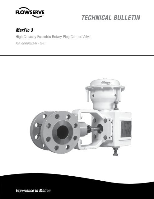
<strong>MaxFlo</strong> 3 FCD VLENTB0052-01 – 01/11Cv (Flow Capacity) TablesTable 4: <strong>MaxFlo</strong> 3 Cv at Full Travel (Inherent characteristic is linear)Flow-to-Close(shaft up)<strong>Valve</strong> Size1 (25)1.5 (40)2 (50)3 (80)4 (100)6 (150)8 (200)10 (250)12 (300)SeatNR (Diaphragm) Actuator60 degree travelNR (Diaphragm) Actuator80 degree travelVR or Supernova Actuator90 degree travelPercent of Full Area 100% % F/A 100% % F/A 100%15% 20% 40% 70% (Full Area) 40% 70% (Full Area) 40% 70% (Full Area)Metal 2* 3* 6.64 11.6 16.6 - - 20.4 8.41 14.7 21Soft Seat - - 4.74 6.65 9.65 - - 11.9 6 8.41 12.2Metal - - 15.7 27.5 39.3 - - 48.4 19.9 35 50Soft Seat - - 15.7 27.7 33.2 - - 40.9 19.9 35 42Metal - - 19.1 33.7 61.6 - - 75.9 24 43 78Soft Seat - - 19 34 54.6 - - 67.2 24 43 69Metal - - 75.2 132 169 - - 208 95 167 214Soft Seat - - 75.1 132 169 - - 208 95 167 214Metal - - 119 174 239 - - 294 150 220 302Soft Seat - - 119 174 239 - - 294 150 220 302Metal - - 256 448 577 - - 711 324 567 730Soft Seat - - 256 448 577 - - 711 324 567 730Metal - - - 670 893 - - 1100 - 847 1130Soft Seat - - - 670 894 - - 1100 - 847 1130Metal - - - 1060 1410 - - 1740 - 1340 1780Soft Seat - - - 1060 1410 - - 1740 - 1340 1780Metal - - - 1520 2020 - - 2490 - 1920 2560Soft Seat - - - 1520 2020 - - 2490 - 1920 2560*Cv 2 and CV 3 have Quick-Open characteristic. Linearize with any <strong>Flowserve</strong> positioner characterized =%Flow-to-Open(shaft down)<strong>Valve</strong> Size1 (25)1.5 (40)2 (50)3 (80)4 (100)6 (150)8 (200)10 (250)12 (300)SeatNR (Diaphragm) Actuator60 degree travelNR (Diaphragm) Actuator80 degree travelVR or Supernova Actuator90 degree travelPercent of Full Area 100% % F/A 100% % F/A 100%15% 20% 40% 70% (Full Area) 40% 70% (Full Area) 40% 70% (Full Area)Metal 2* 3* 6 9.85 14.1 - - 17.3 7.1 12.5 18Soft Seat - - 4.74 5.61 8.15 - - 10 6 7.1 10.3Metal - - 14.7 25.8 36.8 - - 45.4 19 33 47Soft Seat - - 15 26.1 30.8 - - 38 19 33 39Metal - - 25.1 40.8 62.8 - - 77.4 32 52 80Soft Seat - - 25.3 41.1 56.1 - - 69.1 32 52 71Metal - - 82.2 144 190 - - 235 104 182 241Soft Seat - - 82.2 144 191 - - 235 104 182 241Metal - - 134 211 320 - - 394 170 267 405Soft Seat - - 134 211 320 - - 394 170 267 405Metal - - 302 528 754 - - 930 382 669 955Soft Seat - - - 529 755 - - 930 382 669 955Metal - - - 1010 1340 - - 1650 - 1280 1700Soft Seat - - - 1010 1340 - - 1650 - 1280 1700Metal - - - 1480 1980 - - 2440 - 1880 2500Soft Seat - - - 1490 1980 - - 2440 - 1880 2500Metal - - - 2130 2840 - - 4500 - 2700 3600Soft Seat - - - 2140 2850 - - 3510 - 2700 3600For detailed Cv vs. Position tables visit http://extranet.flowserve.com: <strong>Valve</strong>s > Sizing & Selection > Cv TablesAlso <strong>Flowserve</strong> Perfornace! sizing software (www.flowserveperfornance.com) provides a Cv table utility.flowserve.com5
<strong>MaxFlo</strong> 3 FCD VLENTB0052-01 – 01/11Pressure Drop TablesTable 8: Maximum Allowable Shutoff Pressure Drops (bar/psi)Group12345Components & MaterialPlug: 1.4418 through 8”1.4405 in 10” or 12”Seat: 316L or 316L + Alloy 6Bearing: MetalShaft & Post: 1.4418 Gr660 or17-4 PHPlug: F316/CF3M + Alloy 6Seal: 316L + Alloy 6Bearing: MetalShaft & Post: 1.4418 Gr660 or17-4 PHPlug: F316/CF3M + Alloy 6Seal: 316L + Alloy 6Bearing: PTFE LinedShaft and Post: 1.4418 Gr660 or17-4 PHPlug: 1.4418 through 8”1.4405 in 10” or 12”Seal: 316L + PTFEBearing: Metal/PTFE LinedShaft & Post: 1.4418 Gr660 or17-4 PHPlug: F316/CF3M = Alloy 6Seat: 316L + PTFEBearing: PTFE LinedShaft & Post: 1.4418 Gr660 or17-4 PHTemperature<strong>Valve</strong> Size (in/mm)1 / 25 1.50 / 40 2 / 50 3 / 80 4 / 100FTC/FTObar/psiFTC/FTObar/psiFTC/FTObar/psiFTC/FTObar/psiFTC/FTObar/psi( 0 F) ( 0 C)-20 to 100 -29 to 38 102/1480 102/1480 102/1480 102/1480 90/1305200 93 85/1235 85/1235 85/1235 85/1235 85/1235300 149 76/1102 76/1102 76/1102 76/1102 76/1102400 204 70/1015 70/1015 70/1015 70/1015 70/1015500 260 66/951 66/951 66/951 66/951 66/951600 316 62/905 62/905 62/905 62/905 62/905700 371 60/870 60/870 60/870 60/870 60/870750 400 59/853 59/853 59/853 59/853 59/853-20 to100 -29 to 38 102/1480 102/1480 52/754 52/754 52/754200 93 85/1235 85/1235 50/725 44/642 46/667300 149 76/1102 76/1102 47/682 40/573 43/624400 204 70/1015 70/1015 43/624 36/528 40/580500 260 66/951 66/951 39/566 34/495 37/537600 316 62/905 62/905 35/508 32/470 33 / 479700 371 60/870 60/870 31 / 452 31 / 452 31 / 452750 400 59/853 59/853 30/441 31 / 443 31 / 443-20 to 100 -29 to 38 102/1480 102/1480 52/754 52/754 52/754200 93 82/1189 82/1189 50/725 44/642 41/595300 149 65/943 65/943 47/682 40/573 32/464400 204 52/754 52/754 41/595 36/528 26/377-20 to 100 -29 to 38 52/754 52/754 52/754 52/754 52/754200 93 38/551 38/551 38/551 38/551 38/551300 149 23/334 23/334 23/334 23/334 23/334400 204 10/145 10/145 10/145 10/145 10/145-20 to 100 -29 to 38 52/754 52/754 52/754 52/754 52/754200 93 31 / 450 31 / 450 31 / 450 31 / 450 31 / 450300 149 17/247 17/247 17/247 17/247 17/247400 204 10/145 10/145 10/145 10/145 10/1456
<strong>MaxFlo</strong> 3 FCD VLENTB0052-01 – 01/11Pressure Drop Tables (continued)Table 9: Maximum Allowable Shutoff Pressure Drops (bar/psi)Group12345Components & MaterialPlug: 1.4418 through 8”1.4405 in 10” or 12”Seat: 316L or 316L + Alloy 6Bearing: MetalShaft & Post: 1.4418 Gr660 or17-4 PHPlug: F316/CF3M + Alloy 6Seat: 316L + Alloy 6Bearing: MetalShaft & Post: 1.4418 Gr660 or17-4 PHPlug: F316/CF3M + Alloy 6Seat: 316L + Alloy 6Bearing: PTFE LinedShaft & Post: 1.4418 Gr660 or17-4 PHPlug: 1.4418 through 8”1.4405 in 10” or 12”Seat: 316L + PTFEBearing: Metal/PTFE LinedShaft & Post: 1.4418 Gr660 or17-4 PHPlug: F316/CF3M + Alloy 6Seat: 316L + PTFEBearing: PTFE LinedShaft & Post: 1.4418 Gr660 or17-4 PHTemperatureFTCbar/psi<strong>Valve</strong> Size (in/mm)6 / 150 8 / 200 10 / 250 12 / 300FTObar/psiFTCbar/psiFTObar/psiFTCbar/psiFTObar/psiFTCbar/psiFTObar/psi( 0 F) ( 0 C)-20 to 100 -29 to 39 78/1131 46/667 38/544 31 / 450 23/337 31 / 450 20/289200 93 78/1131 75/1088 46/667 38/544 31 / 450 23/337 31 / 450 20/289300 149 71/1036 45/647 36/528 30/436 23/327 30/436 19/280400 204 66/954 43/627 35/511 29/422 22/317 29/422 19/271500 260 62/894 42/606 34/495 28/409 21/306 28/409 18/263600 316 59/851 40/586 33 / 478 27/395 20/296 27/395 18/254700 371 56/818 39/566 32/462 26/381 20/286 26/381 17/245750 400 55/801 38/546 31 / 445 25/368 19/276 25/368 16/236-20 to 100 -29 to 38 42/609 24/348 24/348 23/337 19/276200 93 36/519 20/296 20/296 16/235300 149 32/463 18/264 18/264 14/209400 204 29/426 17/244 17/244 13/193500 260 28/400 16/228 16/228 12/181600 316 26/380 15/217 15/217 12/172700 371 25/365 14/209 14/209 11/165750 400 25/358 14/205 14/205 11/162-20 to 100 -29 to 38 42/609 24/348 24/348 23/333 19/276 16/233200 93 36/519 20/296 20/296 16/235 16/228300 149 32/463 18/264 18/264 14/209400 2074 26/377 16/232 16/232 13/193-20 to 100 -29 to 38 52/754 46/667 31/450 23/337 31/450 20/289200 93 38/551 36/522 25/363 23/337 25/363 20/289300 149 23/334 23/334 17/247 17/247400 204 10/145 8/116 10/145 10/145-20 to 100 -29 to 38 42/609 24/348 24/348 23/333 19/276 16/233200 93 31 / 450 20/296 20/296 16/235 16/228300 149 17/247 17/247 17/247 14/209400 204 10/145 10/145 10/145 10/1451. If higher pressure drops are required, contact your <strong>Flowserve</strong> sales office.2. Additional material combinations are available. Contact your <strong>Flowserve</strong> sales office for respective pressure drops.Note: Values are for combinations shown only. Consult <strong>Flowserve</strong> for other alloys such as Hastelloy-C, Nickel 500, Duplex, etc. DO NOT EXCEED Pressure/Temperature limits per ASME B16.34 for body materials.Note: Allowable pressure drops for other alloys will be evaluated on application.7flowserve.com
<strong>MaxFlo</strong> 3 FCD VLENTB0052-01 – 01/11Dimensions and WeightsTable 10: <strong>MaxFlo</strong> 3 Face-to-face Dimensions<strong>Valve</strong>Size(in./mm)(ANSI/ISA-75.08.02,EN 558-1/2 Series 36,IEC 60534-3-2)(ANSI/ISA-75.08.01,Class 150, EN 558-1/2Series 37-38, IEC60534-3-1)(ANSI/ISA-75.08.01Class 300, EN 558-1/2Series 37-38, IEC 60534-3-1)(DIN 3202 F1,EN 558-1/2 Series 1)A B A B A B A Bin. mm in. mm in. mm in. mm in. mm in. mm in. mm in. mm1/25 4.02 102 2.01 51 7.25 184 4.76 121 7.75 197 5.16 131 6.30 160 3.74 951.5/40 4.49 114 2.24 57 8.75 222 5.83 148 9.25 235 6.22 158 7.87 200 4.96 1262/50 4.88 124 2.44 62 10.00 254 6.89 175 10.50 267 7.28 185 9.06 230 5.98 1523/80 6.50 165 3.25 83 11.75 298 7.48 190 12.50 318 8.11 206 12.21 310 8.03 2044/100 7.64 194 3.82 97 13.88 353 9.17 233 14.50 368 9.49 241 13.78 350 9.17 233SS6/150 9.02 229 4.65 118 17.75 451 11.57 294 18.62 473 12.01 305 18.90 480 12.64 3218/200 9.57 243 5.35 136 21.38 543 15.28 388 22.38 568 15.75 400 23.62 600 16.61 42210/250 11.69 297 6.22 158 26.50 673 19.88 505 27.88 708 20.55 522 28.74 730 20.98 53312/300 13.31 338 6.77 172 29.00 737 21.57 548 30.50 775 22.32 567 33.47 850 25.12 638Table 11: Shipping Weights for Body Sub-Assembly (Weights for all class ratings)ISA 75.08.01 FFABSAFigure 3: <strong>MaxFlo</strong> 3 Face-to-face OptionsBISA 75.08.02 FFFlanged Flanged FlangelessABSSAABBSAS. No SizeCL 150 CL 300CL 150/PN 10Thru PN 40CL 300 CL 600/PN 63CL 150/PN 10Thru PN 40Cl 300/PN 40 CL 600/PN 63Kg Lbs Kg Lbs Kg Lbs Kg Lbs Kg Lbs Kg Lbs Kg Lbs Kg Lbs1 1” 6 14 8 17 5 12 6 14 7 16 5 10 5 10 5 102 1.50” 9 19 11 24 7 16 10 21 11 24 6 13 6 14 6 133 2” 11 24 12 27 9 19 11 23 12 27 7 15 8 17 9 214 3” 20 45 24 53 17 38 21 45 23 51 12 27 15 33 19 415 4” 24 53 32 71 19 42 26 58 37 82 14 31 17 37 24 546 6” 48 106 65 142 36 79 50 110 74 163 28 62 39 86 50 1107 8” 70 155 92 204 52 115 71 157 109 240 37 82 52 115 68 1518 10” 136 300 172 380 105 231 134 295 206 454 86 191 107 235 139 3069 12” 195 429 243 537 151 333 187 411 252 555 119 262 142 314 177 3898
<strong>MaxFlo</strong> 3 FCD VLENTB0052-01 – 01/11Dimensions and Weights (continued)Table 12: Diaphragm Actuator SpecificationsTypeSizesActionSupply PressureAuxiliarySingle-acting, high-performanceNR1, NR2, NR3Air-to-open, Air-to-close, Fail-in-place60 psig/4 barg* (maximum)Push-type handwheelStroke 60° and 80°Spring Ranges0.2 to 1, 0.7 to 1.9, 1.4 to 2.8 bar, and 1.9 to 3.8 bar* Some restrictions may apply to certain applicationsTable 13: <strong>Valve</strong> Size / NR Diaphragm Actuator CompatibilityActuatorSize<strong>Valve</strong> Size (in./mm)Weight1/25 1.5/40 2/50 3/80 4/100 6/150 8/200 10/250 12/300 Kg LbsNR 1 X X X 16 35NR 2 X X 38 85NR 3 X X X X 88 195Table 14: <strong>MaxFlo</strong> 3 Dimensions with Diaphragm Actuator<strong>Valve</strong>Size(in./mm)D E E(Max) F L Min. mm in. mm in. mm in. mm in. mm in. mm1/25 12.80 325 3.46 88 8.66 220 2.13 54 9.72 247 5.43 1381.5/40 13.78 350 3.46 88 8.66 220 2.13 54 9.80 249 5.43 1382/50 13.86 352 3.46 88 8.66 220 2.13 54 9.80 249 5.43 1383/80 20.31 516 4.92 125 12.20 310 3.54 90 14.09 358 8.58 2184/100 20.51 521 4.92 125 12.20 310 3.54 90 14.09 358 8.58 2186/150 25.71 653 6.42 163 17.72 450 4.25 108 19.53 496 12.28 3128/200 26.14 664 6.42 163 17.72 450 4.25 108 19.53 496 12.28 31210/250 28.86 733 6.42 163 17.72 450 4.25 108 19.72 501 12.28 31212/300 29.84 758 6.42 163 17.72 450 4.25 108 19.72 501 12.28 312For face-to-face dimensions, see Table 14.All dimensions are to be used for estimation only. Certified drawings will be supplied upon request.Table 12: NR Diaphragm Actuator Shipping WeightsModel Kg LbsNR1 16 35NR2 38 85NR3 88 195FFigure 4: <strong>MaxFlo</strong> 3Diaphragm ActuatorLME Max.ED9flowserve.com
<strong>MaxFlo</strong> 3 FCD VLENTB0052-01 – 01/11Dimensions and Weights (continued)Table 15: Cylinder Actuator SpecificationsTypeSizes 25, 50, 100, 200ActionSupply PressureAuxiliaryStroke 90°Double-acting, cylinder with fail-safe spring actionAir-to-open, Air-to-close, Fail-in-place150 psig/10.3 barg* (maximum)Declutchable side-mounted; manual gear operated; handleverSprings Standard, extended (sizes 25 & 50), dual sizes (100 & 200)* Some restrictions may apply to certain applicationsTable 16: VR Cylinder Actuator Shipping WeightsModel Kg Lbs25 16 3550 33 73100 73 161200 120 26510Table 17: <strong>Valve</strong> Size / VR Cylinder Actuator CompatibilityActuatorSize(in 2 )SpringType<strong>Valve</strong> Size (in./mm)Weights1/25 1.5/40 2/50 3/80 4/100 6/150 8/200 10/250 12/300 Kg Lbs25 STD X X X X X25 EXTD X X X X X16 3550 STD X X X X X50 EXTD X X X X X33 73100 STD X X X100 DUAL X X X X73 161200 STD X X X X200 DUAL X X X X120 265Table 18: <strong>MaxFlo</strong> 3 Dimensions (Spring Cylinder Actuator)<strong>Valve</strong>Size(in./mm)ActuatorSizeCLEDisassemblyClearanceFigure 5: <strong>MaxFlo</strong> 3Spring Cylinder ActuatorShaft Size C D E F L Min. mm in. mm in. mm in. mm in. mm in. mm in. mm1/25 25 0.4 11 6.0 152 20.0 510 5.6 142 2.2 56 13.1 332 4.3 1091.5/40 25 0.6 16 6.0 152 21.0 535 5.6 142 2.2 56 13.1 332 4.3 1092/50 25 0.6 16 6.0 152 21.0 535 5.6 142 2.2 56 13.1 332 4.3 1092/50 50 0.6 16 8.0 203 21.0 535 6.7 170 2.5 64 18.0 457 6.6 1683/80 25 0.9 23 6.0 152 25.0 635 5.6 142 2.2 56 13.1 332 4.3 1093/80 50 0.9 23 8.0 203 25.0 635 6.7 170 2.5 64 18.0 457 6.6 1684/100 25 0.9 23 6.0 152 26.0 661 5.6 142 3.9 99 13.1 332 8.7 2214/100 50 0.9 23 8.0 203 26.0 661 6.7 170 2.5 64 18.0 457 6.6 1686/150 50 1.0 26 8.0 203 27.0 680 6.7 170 2.5 64 18.0 457 6.6 1686/150 100 1.5 38 11.0 279 29.0 722 9.1 231 3.9 99 22.6 574 8.7 2218/200 50 1.0 26 8.0 203 27.0 685 6.7 170 2.5 64 18.0 457 6.6 1688/200 100 1.5 38 11.0 279 29.0 733 9.1 231 3.9 99 22.6 574 8.7 22110/250 50 1.0 26 8.0 203 30.0 751 6.7 170 2.5 64 18.0 457 6.6 16810/250 100 1.5 38 11.0 279 32.0 802 9.1 231 3.9 99 22.6 576 8.7 22112/300 100 1.5 38 11.0 279 33.0 827 9.1 231 3.9 99 22.6 576 8.7 221For face-to-face dimensions, see Table 14.All dimensions are to be used for estimation only. Certified drawings will be supplied up request.FMDisassemblyClearanceD
<strong>MaxFlo</strong> 3 FCD VLENTB0052-01 – 01/11Dimensions and Weights (continued)Table 19: SuperNova Actuator SpecificationsTypeSingle-acting spring-return, double-actingSizes B063, B085, B100, B115, B125, B150, B175, B200, SNA 250, SNA 300Action Air-to-open, air-to-close, fail-in-placeSupplyPressure100 psig/6.9 barg* (maximum) single-acting150 psig/10.34 barg (maximum) double-actingAuxiliary Declutchable handwheelStroke 90°Springs 5 to 12 springs available* Some restrictions may apply to certain applicationsTable 20: <strong>Valve</strong> Size / SuperNova Actuator CompatibilityActuator<strong>Valve</strong> Size (in./mm)WeightSize 1/25 1.5/40 2/50 3/80 4/100 6/150 8/200 10/250 12/300 Kg/LbB063 X X X X 2/4.4B085 X X X X 4.2/9.3B100 X X X X X X 6.6/14.6B115 X X X X X X 10.2/22.5B125 X X X X X X X X X 13.7/30.2B150 X X X X X X X X X 23.2/51.2B175 X X X X X X 35/77.2B200 X X X X X 53/118Table 21: SuperNova Actuator Shipping WeightsModel1” 1.50” 2” 3” 4” 6” 8” 10” 12”Kg Lbs Kg Lbs Kg Lbs Kg Lbs Kg Lbs Kg Lbs Kg Lbs Kg Lbs Kg LbsB063 5 10 5 10 5 10B085 8 17 8 17 8 17 8 19 8 19B100 10 22 10 22 10 22 11 24 11 24B115 17 37 17 37 17 37 17 38 17 38 19 41 19 41B125 21 45 21 45 21 45 21 45 21 45 22 49 22 49 26 57 26 57B150 30 67 30 67 30 67 30 67 30 67 29 64 30 66 32 71 32 71B175 43 94 43 94 48 106 48 106 50 110 50 110B200 61 135 61 135 67 147 67 147 69 152 69 15211flowserve.com
<strong>MaxFlo</strong> 3 FCD VLENTB0052-01 – 01/11Dimensions and Weights (continued)12Table 22: <strong>MaxFlo</strong> 3 Dimensions (Supernova Actuator)ModelB063B085B100B115B125B150B175B200SizeD E F L Min. mm in. mm in. mm. in. mm. in. mm1” 12.0 304 3.5 89 4.0 101 3.5 89 4.0 1011.5” 12.6 320 3.5 89 4.0 101 3.5 89 4.0 1012” 12.7 322 3.5 89 4.0 101 3.5 89 4.0 1011” 12.9 328 3.5 89 4.9 125 3.5 89 4.9 1251.5” 13.6 344 3.5 89 4.9 125 3.5 89 4.9 1252” 13.6 346 3.5 89 4.9 125 3.5 89 4.9 1253” 16.6 423 4 102 4.9 125 4 102 4.9 1254” 16.8 428 4 102 4.9 125 4 102 4.9 1251” 13.6 345 3.5 89 11.7 296 3.5 89 11.7 2961.5” 14.5 361 3.5 89 11.7 296 3.5 89 11.7 2962” 14.3 363 3.5 89 11.7 296 3.5 89 11.7 2963” 17.3 439 4 102 11.7 296 4 102 11.7 2964” 17.5 444 4 102 11.7 296 4 102 11.7 2966” 23.5 597 5 127 11.7 296 5 127 11.7 2961” 14.5 368 3.5 89 6.7 171 3.5 89 6.7 1711.5” 15.1 384 3.5 89 6.7 171 3.5 89 6.7 1712” 15.2 386 3.5 89 6.7 171 3.5 89 6.7 1713” 20.2 513 4 102 6.7 171 4 102 6.7 1714” 20.4 518 4 102 6.7 171 4 102 6.7 1716” 24.4 620 5 127 6.7 171 5 127 6.7 1711” 15.0 380 3.5 89 7.9 201 3.5 89 7.9 2011.5” 15.6 396 3.5 89 7.9 201 3.5 89 7.9 2012” 15.7 398 3.5 89 7.9 201 3.5 89 7.9 2013” 20.7 525 4 102 7.9 201 4 102 7.9 2014” 20.9 530 4 102 7.9 201 4 102 7.9 2016” 24.9 632 5 127 7.9 201 5 127 7.9 2018” 25.3 643 5 127 7.9 201 5 127 7.9 20110” 27.2 690 5 127 7.9 201 5 127 7.9 20112” 28.2 715 5 127 7.9 201 5 127 7.9 2011” 16.0 407 3.5 89 9.6 243 3.5 89 9.6 2431.5” 16.7 423 3.5 89 9.6 243 3.5 89 9.6 2432” 16.7 425 3.5 89 9.6 243 3.5 89 9.6 2433” 21.7 552 4 102 9.6 243 4 102 9.6 2434” 21.9 557 4 102 9.6 243 4 102 9.6 2436” 24.6 626 4.3 110 9.6 243 4.3 110 9.6 2438” 26.4 670 5 127 9.6 243 5 127 9.6 24310” 28.2 717 5 127 9.6 243 5 127 9.6 24312” 29.2 742 5 127 9.6 243 5 127 9.6 2433” 23.1 587 4.2 106 10.7 271 4 102 10.7 2714” 23.3 592 4.2 106 10.7 271 4 102 10.7 2716” 27.3 694 5 127 10.7 271 5 127 10.7 2718” 27.7 705 5 127 10.7 271 5 127 10.7 27110” 29.6 752 5 127 10.7 271 5 127 10.7 27112” 30.6 777 5 127 10.7 271 5 127 10.7 2714” 24.5 622 4.7 120 12.2 310 4.3 108 12.2 3106” 28.5 723 5 127 12.2 310 5 127 12.2 3108” 28.9 734 5 127 12.2 310 5 127 12.2 31010” 30.8 781 5 127 12.2 310 5 127 12.2 31012” 31.8 806 5 127 12.2 310 5 127 12.2 310
<strong>MaxFlo</strong> 3 FCD VLENTB0052-01 – 01/11Dimensions and SpecificationsLogix 500 Series High Performance Digital PositionerEXTERIORGROUNDINGSCREWLED WINDOWInput SignalInput SignalCompliance VoltageVoltage SupplyMinimum RequiredOperating Current4-20 mA HART10 VDC30 VDC3.6 mAM20X1,5 OR1/2" NPTFRONT VIEWG1/4" OR1/4" NPTStroke OutputFeedback ShaftRotationmin. 15 0 , max 90 0 ,40 0 recommended forlinear applications22.95.9010.00.39"D" SHAFT OPTION(STANDARD)M857.202.25Air Supply2.31.0928.601.1335.401.39Air Supply Quality17.70.70Input Pressure RangeAir Consumption(steady state)17.70.7064.102.5235.401.3957.202.25174.106.8528.601.13free from moisture, oiland dust per IEC 770 andISA-7.0.011.6 to 6.0 bar (22 to 87 psi)0.08 Nm 3 /h @ 1.5 bar(0.047 SCFM @ 22 psi)0.12 Nm 3 /h @ 6.0 bar(0.071 SCFM @ 87 psi)Environmental Conditions-40Operating Temperature0 C to +80 0 C(-40 0 F to +178 0 F)Transport and Storage -40 0 C to +80 0 CTemperature(-40 0F to +178 0 F)Operating Humidity 0 to 100% non-condensatingM6BACK VIEW98.143.953.002.094.80.210.00.4M8X1,25 OR 5/16"-18UNC100.003.944.00.2"N" SHAFT OPTION(VDI/VDE 3845, NAMUR)MMINCH32.001.34.00.2Output SignalOutput PressureRangeOutput FlowCapacityShipping WeightsBase Positioner withoutAccessories0 to 100% of airsupply pressure2.4 Nm 3 /h @ 1.5 bar(1.41 SCFM @ 22 psi)7.0 Nm 3 /h @ 6.0 bar(4.12 SCFM @ 87 psi)1.2 kg (2.65 lbs)Performance Characteristics (typical)Linearity < +/- 1.0%Resolution < 0.1%Repeatability < 0.2%Deadband < 0.2%Limit Switches (optional)TypeP&F SJ2-S1NLoad current< 1 mA < 3 mAVoltage range5 - 25 VDCHysteresis 0.2%Temperature -25 0 C to 100 0 C (-13 0 F to 212 0TypeP&F SJ2-SNLoad Current< 1 mA < 3 mAVoltage Range5 - 25 VDCHysteresis 0.2%Temperature -40 0 C to 100 0 C (-40 0 F to 212 0 F)TypeP&F SJ2-NLoad Current< 1 mA < 3 mAVoltage Range5 - 25 VDCHysteresis 0.2%Temperature -25 0 C to 100 0 C (-13 0 F to 212 0 F)flowserve.com13
0.97(24.69)<strong>MaxFlo</strong> 3 FCD VLENTB0052-01 – 01/114.00(101.60)Customer conduit ports½-14 NPT thread(M20 optional)Dimensions and SpecificationsLogix 3000MD Series High Performance Digital PositionerNOTE: Dimensions in inches (mm)Supply, Output 1 andOutput 2 ports¼-18 NPT thread5.92(150.24)10.63(269.92)Follower arm limitis ±45° from 4.05 positionshown, (102.74) maximum0.25(6.35)2.00(50.80)Supply, Output 1 andOutput 2 ports¼-18 NPT thread7.18(182.45)5.92(150.24)3.38(85.83)10.63(269.92)4.05(102.74)2.70(68.68)0.15(3.81)1.24(31.59)0.86(21.76)1.13(28.58)2.25(57.15)Square5.24(133.15)Drive3.38(85.83)1.24(31.59)0.86(21.76)0.97(24.69)0.75(19.05)7.18(182.45)4.00(101.60)Customer conduit ports½-14 NPT thread(M20 optional)1.00(25.40)0.97(24.69)Spool <strong>Valve</strong> Cover and VentLED IndicatorsMain CoverFollower arm limitis ±45° from positionshown, maximum4.00(101.60)0.25(6.35)2.00(50.80)Customer conduit ports½-14 NPT thread(M20 optional)Spool <strong>Valve</strong> Cover and VentLED IndicatorsCustomerInterfaceCoverDriver CoverMain CoverElectrical Specifications Logix 3200MDPower SupplyCompliance VoltageEffective ResistanceTwo-wire, 4-20 mA10.0 to 30.0 VDCFollower arm limitis ±45° from positionshown, maximum10.0 VDC @ 20 mA2.70(68.68)0.15(3.81)2.70(68.68)0.15(3.81)0.25(6.35)495 Ω @ 20 mA TypicalAdd 20 Ω when HART communication activeCommunications HART Protocol ITK 5,6Minimum OperatingCurrentMaximum Voltage3.6 mA without AO board3.7 mA with AO board30.0 VDCEnvironmental Conditions Logix 3200MDOperating Temperature RangeStandardLow1.00(25.40)2.00(50.80)0.75(19.05)-4° to 176°F(-20° to 80°C)-40° to 176°F(-40° to 80°C)1.00(25.40)1.13(28.58)0.75(19.05)Electrical Specifications Logix 3400MD2.25(57.15)Square1.13(28.58)Power SupplyIS5.24(133.15)2.25(57.15)Square5.24(133.15)Two-wire, 9-32 VDCFF compatibleFisco compliantDriver CoverCommunications FF Protocol ITK 4.6x, 5.0Operating CurrentMaximum Voltage23 mA36.0 VDCEnvironmental Conditions Logix 3400MDOperating TemperatureRangeTransport and StorageTemperature RangeOperating HumidityStandardCustomerInterfaceCover-40° to 176°F(-40° to 80°C)-40° to 176°F (-40° to 80°C)0 - 100% non-condensingNote: The air supply must conform to ISA Standard ISA 7.0.01 (a dew point at least 18degrees Fahrenheit below ambient temperature, particle size below five microns—one micronrecommended—and oil content not to exceed one part per million).14Transport and StorageTemperature RangeOperating Humidity-40° to 176°F (-40° to 80°C)0 - 100% non-condensingNote: The air supply must conform to ISA Standard ISA 7.0.01 (a dew point at least 18degrees Fahrenheit below ambient temperature, particle size below five microns—one micronrecommended—and oil content not to exceed one part per million).
<strong>MaxFlo</strong> 3 FCD VLENTB0052-01 – 01/11Table 23: <strong>MaxFlo</strong> 3 Pipe Mounting Orientation Codes3 - Air Action 4 - Pipe Configuration 5 - Actuator Orientation 6 - Shaft DirectionO Air-to-open - ATO L Left Hand Mounting T Top (Default) D Shaft Downstream (Default)C Air-to-close - ATC R Right Hand Mounting R Right U Shaft UpstreamD Flow Down L LeftU Flow Up B Bottom*P Supernova: ParallelX Supernova: Cross-PipeAT3 4 5 6* Not available on diaphragm actuatorsTable 24: <strong>MaxFlo</strong> 3 Mounting Orientations – Diaphragm ActuatorFlow-to-Open (Shaft Downstream)AIR-TO-CLOSE, FAIL OPEN CONFIGURATIONFlow-to-Close (Shaft Upstream)TOPTOPHORIZONTAL FLOWLEFTRIGHTAIR TO CLOSERIGHTTOPLEFTFLOWAIR TO CLOSEFLOWLEFTRIGHTAIR TO CLOSETOPFLOWRIGHTLEFTAIR TO CLOSEFLOWFLOWLEFT HAND PIPEMOUNTINGRIGHT HAND PIPEMOUNTINGFLOWTOPTOPAIR TO CLOSERIGHTAIR TO CLOSERIGHTFLOW DOWNVERTICAL FLOWLEFTFLOWTOPRIGHTAIR TO CLOSELEFTFLOWTOPRIGHTAIR TO CLOSEFLOW UP15LEFTLEFTflowserve.com
<strong>MaxFlo</strong> 3 FCD VLENTB0052-01 – 01/11Table 25: <strong>MaxFlo</strong> 3 Mounting Orientations - Diaphragm ActuatorAIR-TO-OPEN, FAIL CLOSE CONFIGURATIONFlow-to-Open (Shaft Downstream)Flow-to-Close (Shaft Upstream)HORIZONTAL FLOWLEFTRIGHTAIR TO OPENFLOWTOPTOPRIGHTLEFTAIR TO OPENFLOWLEFTRIGHTAIR TO OPENFLOWTOPTOPAIR TO OPENRIGHTLEFTFLOWLEFT HAND PIPE MOUNTINGRIGHT HAND PIPE MOUNTINGFLOWTOPFLOWTOPAIR TO OPENAIR TO OPENRIGHTRIGHTFLOW DOWNVERTICAL FLOWLEFTFLOWTOPLEFTFLOWTOPRIGHTRIGHTAIR TO OPENAIR TO OPENFLOW UP16LEFTLEFT
<strong>MaxFlo</strong> 3 FCD VLENTB0052-01 – 01/11Table 26: <strong>MaxFlo</strong> 3 Mounting Orientations - Cylinder ActuatorAIR-TO-CLOSE, FAIL OPEN CONFIGURATIONFlow-to-Open (Shaft Downstream)Flow-to-Close (Shaft Upstream)HORIZONTAL FLOWLEFTBOTTOMRIGHTAIR TO CLOSETOPFLOWTOPRIGHTLEFTBOTTOMAIR TO CLOSEFLOWLEFTAIR TO CLOSERIGHTTOPAIR TO CLOSERIGHTBOTTOMTOPLEFTFLOWBOTTOMFLOWLEFT HAND PIPE MOUNTINGRIGHT HAND PIPE MOUNTINGFLOWTOPFLOWTOPAIR TO CLOSERIGHTAIR TO CLOSERIGHTFLOW DOWNVERTICAL FLOWAIR TO CLOSELEFTBOTTOMTOPAIR TO CLOSELEFTTOPBOTTOMRIGHTRIGHTFLOWFLOWFLOW UPLEFTLEFT17BOTTOMBOTTOMflowserve.com
<strong>MaxFlo</strong> 3 FCD VLENTB0052-01 – 01/11Table 27: <strong>MaxFlo</strong> 3 Mounting Orientations - Cylinder ActuatorAIR-TO-OPEN, FAIL CLOSE CONFIGURATIONFlow-to-Open (Shaft Downstream)Flow-to-Close (Shaft Upstream)TOPTOPHORIZONTAL FLOWLEFTRIGHTAIR TO OPENFLOWRIGHTBOTTOMTOPLEFTBOTTOMAIR TO OPENFLOWLEFTAIR TO OPENRIGHTFLOWRIGHTBOTTOMTOPLEFTBOTTOMAIR TO OPENFLOWLEFT HAND PIPE MOUNTINGFLOWFLOWRIGHT HAND PIPE MOUNTINGTOPTOPAIR TO OPENRIGHTAIR TO OPENRIGHTFLOW DOWNVERTICAL FLOWLEFTTOPBOTTOMRIGHTLEFTTOPBOTTOMRIGHTAIR TO OPENAIR TO OPENFLOWFLOWFLOWFLOW UP18LEFTLEFTBOTTOMBOTTOM
<strong>MaxFlo</strong> 3 FCD VLENTB0052-01 – 01/1119flowserve.com
<strong>Flowserve</strong> CorporationFlow <strong>Control</strong>1350 N. Mt. Springs ParkwaySpringville, UT 84663USAPhone: 801 489 8611Fax: 801 489 3719<strong>Flowserve</strong> S.A.S.7 Avenue de la Libération deThiersB.P. 6063307 Thiers CedexFrancePhone: 33 (0) 4 73 80 42 66Fax: 33 (0) 4 73 80 14 24FCD VLENTB0052-01 – 01/11Printed in USA.To find your local <strong>Flowserve</strong> representative:For more information about <strong>Flowserve</strong> Corporation, visitwww.flowserve.com or call USA 1 800 225 6989<strong>Flowserve</strong> Pte Ltd.12 Tuas Avenue 20Singapore 638824SingaporePhone: 65 6868 4600Fax: 65 6862 4940<strong>Flowserve</strong> Australia Pty Ltd.14 Dalmore DriveScoresby, Victoria 3179AustraliaPhone: 61 7 32686866Fax: 61 7 32685466<strong>Flowserve</strong> Ltda.Rua Tocantins, 128São Caetano do Sul, SP 09580-130BrazilPhone: 55 11 2169 6300Fax: 55 11 2169 6313<strong>Flowserve</strong> Corporation has established industry leadership in the design and manufacture of its products. When properly selected, this <strong>Flowserve</strong> product is designed toperform its intended function safely during its useful life. However, the purchaser or user of <strong>Flowserve</strong> products should be aware that <strong>Flowserve</strong> products might be used innumerous applications under a wide variety of industrial service conditions. Although <strong>Flowserve</strong> can (and often does) provide general guidelines, it cannot provide specific dataand warnings for all possible applications. The purchaser/user must therefore assume the ultimate responsibility for the proper sizing and selection, installation, operation, andmaintenance of <strong>Flowserve</strong> products. The purchaser/user should read and understand the Installation Operation Maintenance (IOM) instructions included with the product, andtrain its employees and contractors in the safe use of <strong>Flowserve</strong> products in connection with the specific application.While the information and specifications contained in this literature are believed to be accurate, they are supplied for informative purposes only and should not be consideredcertified or as a guarantee of satisfactory results by reliance thereon. Nothing contained herein is to be construed as a warranty or guarantee, express or implied, regarding anymatter with respect to this product. Because <strong>Flowserve</strong> is continually improving and upgrading its product design, the specifications, dimensions and information containedherein are subject to change without notice. Should any question arise concerning these provisions, the purchaser/user should contact <strong>Flowserve</strong> Corporation at any one of itsworldwide operations or offices.© 2010 <strong>Flowserve</strong> Corporation, Irving, Texas, USA. <strong>Flowserve</strong> is a registered trademark of <strong>Flowserve</strong> Corporation.flowserve.com