Mesoscale Simulation of Blood Flow in Small Vessels
Mesoscale Simulation of Blood Flow in Small Vessels
Mesoscale Simulation of Blood Flow in Small Vessels

You also want an ePaper? Increase the reach of your titles
YUMPU automatically turns print PDFs into web optimized ePapers that Google loves.
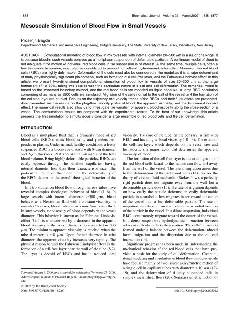
<strong>Mesoscale</strong> <strong>Simulation</strong> <strong>of</strong> <strong>Blood</strong> <strong>Flow</strong> 1859RBCs <strong>in</strong> cyl<strong>in</strong>drical capillaries has also been addressed (21).Development <strong>of</strong> more realistic simulation <strong>of</strong> multiple redblood cells flow<strong>in</strong>g through vessels <strong>of</strong> diameter 10–500 mmhas rema<strong>in</strong>ed a major challenge. It is because blood <strong>in</strong> suchvessels behaves as a multiphase suspension <strong>of</strong> deformableparticles. While a cont<strong>in</strong>uum description <strong>of</strong> blood issufficient for average flow pr<strong>of</strong>ile, it is not so if the motion<strong>of</strong> <strong>in</strong>dividual cells and their <strong>in</strong>teraction are concerned. Thesize <strong>of</strong> the RBCs is comparable to the size <strong>of</strong> the vessels, andhence each cell must be taken <strong>in</strong>to consideration <strong>in</strong> themodel<strong>in</strong>g. At the same time, multiple cells, <strong>of</strong>ten <strong>of</strong> the order<strong>of</strong> a few thousands <strong>in</strong> number, must be considered to realisticallysimulate a microvessel. Any computational modelaimed at understand<strong>in</strong>g blood flow <strong>in</strong> microvessels must take<strong>in</strong>to consideration the deformability <strong>of</strong> the <strong>in</strong>dividual redblood cell, and an ensemble <strong>of</strong> a large population <strong>of</strong> cells.A significant step <strong>in</strong> the simulations <strong>of</strong> flow<strong>in</strong>g multipleRBCs has been achieved by Sun and Munn (22), who useda Lattice-Boltzmann simulation to address blood flow <strong>in</strong>20–40 mm two-dimensional channels and at hematocrit <strong>of</strong>10–30%. The simulations were two-dimensional, but theresults showed that apparent viscosity <strong>of</strong> the suspension<strong>in</strong>creases with <strong>in</strong>creas<strong>in</strong>g volume fraction <strong>of</strong> the particles,which is <strong>in</strong> agreement with the earlier observations withsuspensions <strong>of</strong> RBC, and other rigid particles. However, theRBCs <strong>in</strong> their simulation were modeled as rigid disks, ratherthan deformable particles. Further, the range <strong>of</strong> channel sizeis not large enough to show the nonl<strong>in</strong>ear behavior <strong>of</strong> theapparent viscosity with vary<strong>in</strong>g channel size. It should alsobe noted that at very high volume fractions, which were notconsidered by Sun and Munn, rigid particles can stop theflow. This is not the case with RBCs due to their flexibility.In this article, we present computational simulation <strong>of</strong> themotion <strong>of</strong> red blood cells flow<strong>in</strong>g through two-dimensionalchannels <strong>of</strong> size 20–300 mm. Similar to the work <strong>of</strong> Sunand Munn (22), we consider two-dimensional simulations.However, the deformability <strong>of</strong> the cells is <strong>in</strong>cluded <strong>in</strong> ourmodel. Moreover, a large cell population compris<strong>in</strong>g <strong>of</strong> ashigh as 2500 red blood cells are simulated. To the best <strong>of</strong>our knowledge, this article presents the first simulation toconsider such a large ensemble <strong>of</strong> deformable cells, though<strong>in</strong> two dimensions. As we will see later, many characteristics<strong>of</strong> the RBC motion, formation <strong>of</strong> the cell-free layer, and theFahraeus-L<strong>in</strong>dqvist effect are quite accurately predicted byour two-dimensional simulations.The structure <strong>of</strong> the article is as follows. In the nextsection, we describe the simulation technique, followed bypresentation <strong>of</strong> the results. First, we describe the motion <strong>of</strong>an isolated red blood cell flow<strong>in</strong>g through a vessel, andaddress its dynamic behavior, such as lateral migration, tanktread<strong>in</strong>g,and flipp<strong>in</strong>g motion. We then consider simulations<strong>of</strong> multiple cells <strong>in</strong> the range <strong>of</strong> vessel size 20–300 mm anddischarge hematocrit 10–60%. Number <strong>of</strong> RBCs considered<strong>in</strong> a typical simulation ranges from 5 to 2500. Results on thetrajectory and velocity <strong>of</strong> <strong>in</strong>dividual cells and their fluctuationstatistics are presented. The <strong>in</strong>clusion <strong>of</strong> deformabilityallows us to study the formation <strong>of</strong> the cell-free layer. Comparisonsare made with the experimental results (1–4). Wethen present the apparent viscosity <strong>of</strong> blood for vary<strong>in</strong>ghematocrit and vessel diameter, and discuss the Fahraeus-L<strong>in</strong>dqvist effect. The numerical results also allow us to <strong>in</strong>vestigatevariation <strong>of</strong> ‘‘local’’ apparent viscosity across thecross-section <strong>of</strong> the vessel.SIMULATION TECHNIQUE<strong>Flow</strong> configurationThe flow configuration is described <strong>in</strong> Fig. 1. The motion <strong>of</strong>an ensemble <strong>of</strong> red blood cells through a two-dimensionalrectangular channel is considered. The undeformed rest<strong>in</strong>gshape <strong>of</strong> a red blood cell is taken to be a biconcave disk. Inthe figure, the flow is along the x direction and from left toright. The flow is driven by a constant pressure gradient.No-slip conditions are imposed at the walls <strong>of</strong> the channel. Inabsence <strong>of</strong> the cells, the velocity pr<strong>of</strong>ile <strong>of</strong> the pure plasma isparabolic and is given by the Poiseuille law. The height <strong>of</strong>the channel is denoted by H, which is equivalent to the tubediameter <strong>in</strong> case <strong>of</strong> a three-dimensional flow. The computationdoma<strong>in</strong> is a square segment <strong>of</strong> sides <strong>of</strong> length H.Periodic conditions are imposed at the <strong>in</strong>flow (left) andoutflow (right) <strong>of</strong> the doma<strong>in</strong>. The cells that leave the doma<strong>in</strong>through the outflow boundary are brought back <strong>in</strong>to thedoma<strong>in</strong> through the <strong>in</strong>flow boundary.Immersed boundary methodThe simulation technique considered here is the immersedboundary method developed by Pesk<strong>in</strong> (23), and later extendedby Tryggvason and co-workers (24,25) as the fronttrack<strong>in</strong>gmethod for deformable <strong>in</strong>terface. The method hasbeen applied to the simulations <strong>of</strong> suspension <strong>of</strong> liquid dropsand bubbles, and deformation <strong>of</strong> a red blood cell ghost <strong>in</strong>a shear flow (20). The method is particularly suitable forthis study, as the red blood cells are modeled as liquid‘‘capsules.’’ The structure <strong>of</strong> a red blood cell consists <strong>of</strong>hemoglob<strong>in</strong> solution surrounded by a lipid bilayer membrane.The liquidlike nature <strong>of</strong> hemoglob<strong>in</strong>, and the elasticnature <strong>of</strong> the membrane give rise to the deformability <strong>of</strong> thecell. On a mesoscopic scale, the detailed molecular structure<strong>of</strong> the lipid bilayer and the underly<strong>in</strong>g two-dimensionalcytoskeleton network can be neglected. Then, the <strong>in</strong>dividualRBC can be modeled as a liquid capsule, that is, a viscousliquid drop surrounded by a th<strong>in</strong> elastic membrane. Theviscosity <strong>of</strong> the liquid <strong>in</strong>terior (i.e., hemoglob<strong>in</strong>) <strong>of</strong> thecapsule is five times higher than that <strong>of</strong> the exterior liquid(i.e., plasma).In the present model, blood plasma and RBC hemoglob<strong>in</strong>are assumed to behave as Newtonian fluids. TheNewtonian nature <strong>of</strong> these fluids is well established (26). TheBiophysical Journal 92(6) 1858–1877
1860 BagchiFIGURE 1 Schematic <strong>of</strong> the computational doma<strong>in</strong>, andthe Eulerian and Lagrangian grids.non-Newtonian behavior <strong>of</strong> the whole blood primarily arisesdue to deformability <strong>of</strong> <strong>in</strong>dividual RBC. The motion <strong>of</strong> theliquids, plasma, and hemoglob<strong>in</strong>, is governed by the cont<strong>in</strong>uityand Navier-Stokes equations as= u ¼ 0; (1)r @u @t 1 u =u ¼ =p 1 = t 1 F; (2)where u(x, t) is the fluid velocity, r is the density, p pressure,and F is a sourcelike term that arises due to the elastic forcegenerated <strong>in</strong> the cell membrane. The viscous stress tensor t isgiven byt ¼ mð=u 1 ð=uÞ T Þ; (3)where m(x) is the viscosity <strong>of</strong> either the plasma or thehemoglob<strong>in</strong> solution. For any po<strong>in</strong>t with<strong>in</strong> the RBC, m ¼ m r ,and for any po<strong>in</strong>t outside the RBC, m ¼ m p , where m r is theviscosity <strong>of</strong> the RBC hemoglob<strong>in</strong>, and m p is the viscosity <strong>of</strong>the plasma.The ma<strong>in</strong> idea <strong>of</strong> the front-track<strong>in</strong>g method is to use as<strong>in</strong>gle set <strong>of</strong> equations for both fluids, plasma and hemoglob<strong>in</strong>,as <strong>in</strong> Eq. 2. The Navier-Stokes equations for the fluidflow are solved on a fixed Eulerian grid, and the cell-plasma<strong>in</strong>terface is tracked <strong>in</strong> a Lagrangian manner by a set <strong>of</strong>mov<strong>in</strong>g grid, used to discretize the cell membrane as shown<strong>in</strong> Fig. 1. As the cells deform dur<strong>in</strong>g their motion, the cellmembranes are stretched, and elastic forces are generated onthe membrane. The deformation <strong>of</strong> <strong>in</strong>dividual cell alters thesurround<strong>in</strong>g flow. The elastic forces at the cell membranesare coupled to the bulk fluid motion via the source term F <strong>in</strong>Eq. 2 asZFðx; tÞ ¼ fðx9; tÞdðx x9Þdx9; (4)@Swhere f(x9, t) is the elastic force generated <strong>in</strong> the membrane.Here x is the location <strong>of</strong> an arbitrary po<strong>in</strong>t <strong>in</strong> the flowdoma<strong>in</strong>, x9 is any po<strong>in</strong>t on the membrane, and d is theDelta function, which vanishes everywhere except at themembrane. Models for computation <strong>of</strong> f(x9, t) are describedlater.The Navier-Stokes equations are first solved to obta<strong>in</strong> thefluid velocity and pressure. Then the cells are advected <strong>in</strong> aLagrangian manner. The velocity <strong>of</strong> the cell membrane isobta<strong>in</strong>ed by <strong>in</strong>terpolat<strong>in</strong>g the velocity <strong>of</strong> the fluid asZuðx9Þ ¼ uðxÞdðx x9Þdx; (5)Swhere S denotes the entire flow doma<strong>in</strong>. The membrane isthen advected bydx9dt¼ uðx9Þ: (6)The d-functions used <strong>in</strong> Eqs. 4 and 5 are constructedby multiply<strong>in</strong>g one-dimensional delta functions, such asd(x – x9) ¼ d(x – x9)d(y – y9), <strong>in</strong> two dimensions. For numericalimplementation, a smooth representation <strong>of</strong> the d-functionis <strong>in</strong>troduced as (24)Dðx x9Þ ¼ 116 D 2 Y 2i¼11 1 cos p 2D ðx i x9 i Þforjx i x9 i j # 2D; i ¼ 1; 2Dðx x9Þ ¼0 otherwise; (7)where D is the Eulerian grid size. The above representationapproaches the actual delta function as the grid sizeapproaches zero. The discrete d-function is so constructedthat properties, such as viscosity, vary smoothly over fourEulerian grid po<strong>in</strong>ts surround<strong>in</strong>g the RBC membrane. In discreteform, the <strong>in</strong>tegrals <strong>in</strong> Eqs. 4 and 5 can be written asFðx j Þ¼S i Dðx j x9 i Þfðx9 i Þ; (8)uðx9 i Þ¼S j Dðx j x9 i Þuðx j Þ; (9)where i and j represent the Lagrangian and Eulerian gridpo<strong>in</strong>ts, respectively. The above representation needs to bemodified if the <strong>in</strong>terface is located close to a solid boundary.In our simulation, we ensure that the m<strong>in</strong>imum distancebetween the solid boundary and the <strong>in</strong>terface is at least fourEulerian grid size.Biophysical Journal 92(6) 1858–1877
<strong>Mesoscale</strong> <strong>Simulation</strong> <strong>of</strong> <strong>Blood</strong> <strong>Flow</strong> 1861As the cells move to new positions, the viscosity m(x, t)needs to be updated. Follow<strong>in</strong>g Tryggvason and Unverdi andTryggvason (24,25), this is done by first def<strong>in</strong><strong>in</strong>g an <strong>in</strong>dicatorfunction I(x) such thatmðx; tÞ ¼m p 1 ðm r m p ÞIðx; tÞ: (10)To f<strong>in</strong>d the <strong>in</strong>dicator function, we use a Poisson solver aswhere= 2 I ¼ = G; (11)G ¼ S i Dðx j x9 i ÞnDs; (12)and where D is the discrete d-function as given <strong>in</strong> Eq. 7, n isthe unit normal to the cell surface, and Ds is a discrete l<strong>in</strong>esegment on the cell surface. In this way, the direct solution <strong>of</strong>the advection equation for viscosity, and hence the smear<strong>in</strong>g<strong>of</strong> viscosity pr<strong>of</strong>ile across the <strong>in</strong>terface are avoided. Here weavoid the details <strong>of</strong> the method, and refer to articles byTryggvason and co-workers (24,25).RBC modelAs mentioned before, red blood cells <strong>in</strong> this study are modeledas liquid ‘‘capsules,’’ that is, viscous liquid drops surroundedby elastic membranes. The viscosity <strong>of</strong> the liquid<strong>in</strong>terior (i.e., hemoglob<strong>in</strong>) <strong>of</strong> the capsule is five times higherthan that <strong>of</strong> the exterior liquid (i.e., plasma). This differenceis taken <strong>in</strong>to account <strong>in</strong> the immersed boundary methoddescribed above. The deformation <strong>of</strong> the cells under a dynamicfluid motion generates an elastic force f(x9, t) <strong>in</strong> thecell membrane. Computation <strong>of</strong> this force requires a constitutivelaw for the material <strong>of</strong> the membrane. Here weassume that the membrane follows the neo-Hookean law.Note that the neo-Hookean law does not strictly representthe behavior <strong>of</strong> a red blood cell membrane. An RBC membraneis strongly resistant to area dilatation. On the contrary,the neo-Hookean model employed here does allow areadilatation. Membrane models that restrict area dilatation andhence are more accurate for the RBC have been developed(27,28). The present methodology does allow <strong>in</strong>corporation<strong>of</strong> these models. The neo-Hookean model is chosen because<strong>of</strong> its simplicity. An accurate model<strong>in</strong>g <strong>of</strong> cell deformationis not the goal <strong>of</strong> this article. For the present purpose, a cellmodel that takes <strong>in</strong>to account deformability is sufficient.Indeed, it is shown later that the neo-Hookean model caneffectively capture some general characteristics <strong>of</strong> the RBCmotion <strong>in</strong> a shear flow, such as the tank-tread<strong>in</strong>g motion andthe lateral migration.For a two-dimensional neo-Hookean membrane <strong>of</strong> a threedimensionalcell, the stra<strong>in</strong> energy function is given by (20)W ¼ E s hðe 2 1 1 e2 2 1 e 2e 21 2Þ; (13)where E s is the shear modulus <strong>of</strong> elasticity <strong>of</strong> the membrane,h is the thickness, and e 1 and e 2 are the pr<strong>in</strong>cipal stretchratios. The tensions T 1 and T 2 <strong>in</strong> the pr<strong>in</strong>cipal directions arethen given by (29)T 1 ¼ E she 2 11and Te 1 e 2 ðe 1 e 2 Þ 22 ¼ E she 2 12:e 1 e 2 ðe 1 e 2 Þ 2(14)For the two-dimensional simulations considered here, themembrane is a closed curve. A two-dimensional cell is thenequivalent to an actual three-dimensional cell subject to astretch<strong>in</strong>g <strong>in</strong> one direction only. That is, T 1 6¼ 0, T 2 ¼ 0,where 1 <strong>in</strong>dicates the <strong>in</strong>-plane direction along the membrane,and 2 <strong>in</strong>dicates the out-<strong>of</strong>-plane direction normal to Fig. 1.The deformation e 2 <strong>in</strong> the out-<strong>of</strong>-plane direction is not zero.But s<strong>in</strong>ce T 2 ¼ 0, we can express e 2 <strong>in</strong> terms <strong>of</strong> e 1 . Then, fora two-dimensional cell, we haveT ¼ E sh1Þ; (15)e 3=2ðe3where T ¼ T 1 and e ¼ e 1 . For a discretized cell, T is thetension act<strong>in</strong>g along a l<strong>in</strong>e segment connect<strong>in</strong>g two adjacentLagrangian grid po<strong>in</strong>ts on the membrane, and e is the stretchratio (undeformed length by deformed length) <strong>of</strong> the l<strong>in</strong>e segment.At any Lagrangian grid po<strong>in</strong>t on the membrane, twol<strong>in</strong>e segments meet. The membrane elastic force f is then theresultant vector <strong>of</strong> the tensions <strong>in</strong> the two adjacent segments,f ¼ T i e i T j e j ; (16)where i and j denotes two adjacent l<strong>in</strong>e segments, and e i ande j are the unit tangent vectors along them.The RBC membrane also has a bend<strong>in</strong>g resistance. To<strong>in</strong>clude the bend<strong>in</strong>g resistance <strong>in</strong> our simulation, we followthe approach by Pozrikidis (30). Equation 16 is then modifiedasf ¼ T i e i T j e j 1 qn; (17)where q ¼ dm/dl is the transverse shear tension, m ¼ E B (k –k r ) is the bend<strong>in</strong>g moment, E B is the bend<strong>in</strong>g modulus, k isthe local curvature, k r is the reference curvature <strong>in</strong> rest<strong>in</strong>gconfiguration, l is the arc length along the membrane, and nis the unit normal vector at a Lagrangian marker po<strong>in</strong>t on thecell surface.Dimensionless parameters, f<strong>in</strong>ite differencescheme, and resolutionIn absence <strong>of</strong> the cells, the maximum velocity <strong>of</strong> the parabolicflow at the channel center is denoted by U cl . The govern<strong>in</strong>gequations are made dimensionless us<strong>in</strong>g the channelheight H as the characteristic length scale, U cl as the velocityscale, and H/U cl as the timescale. In dimensionless form, theshear modulus <strong>of</strong> elasticity <strong>of</strong> the RBC membrane is givenby E* ¼ m p U cl /E s h, which is the ratio <strong>of</strong> the viscous forceto the elastic force <strong>of</strong> the capsule membrane. The dimensionlessbend<strong>in</strong>g stiffness is expressed as E B * ¼ E B /(a 2 E s ),Biophysical Journal 92(6) 1858–1877
1862 Bagchiwhere a is a characteristic dimension <strong>of</strong> the cell. TheReynolds number <strong>of</strong> <strong>in</strong>dividual RBC, def<strong>in</strong>ed as Re ¼ rU cl a/m p , is much less than unity.In the present model, the dimensionless parameters E*and E B * determ<strong>in</strong>e the deformability <strong>of</strong> the liquid capsule, andhence <strong>of</strong> the red blood cell. For a normal, healthy red bloodcell, E s ¼ 0.006 dyn/cm, and E B 1.8 3 10 12 dyn-cm (6).Under diseased conditions, e.g., <strong>in</strong> sickle cell anemia, thecells lose their deformability. The loss <strong>of</strong> deformability canbe expressed <strong>in</strong> our model <strong>in</strong> terms <strong>of</strong> higher-than-normalvalues <strong>of</strong> E s and E B . Accord<strong>in</strong>gly, the values <strong>of</strong> E* and E B *change as the cell loses its deformability. The value <strong>of</strong> E*also depends on the flow velocity U cl . Note that <strong>in</strong> presence<strong>of</strong> the RBCs, the maximum centerl<strong>in</strong>e velocity is significantlyreduced below U cl if the pressure gradient is keptconstant (shown later <strong>in</strong> Plug-<strong>Flow</strong> Pr<strong>of</strong>ile). The averageflow velocity <strong>in</strong> presence <strong>of</strong> the RBCs is denoted by U m .Inour simulations, U m ranges from ;3 mm/s to 15 mm/s(Table 2). Accord<strong>in</strong>gly, the values <strong>of</strong> E* and E B * used <strong>in</strong> oursimulations ranges from ;0.02–1.0, and 0.0005–0.002,respectively. The higher values <strong>of</strong> E* and lower values <strong>of</strong> E B *typically represent a normal, deformable RBC, whereaslower values <strong>of</strong> E* and higher values <strong>of</strong> E B * represent a lessdeformable RBC. The higher values <strong>of</strong> E* also representhigher flow velocities, and vice versa. The range <strong>of</strong> U mconsidered here matches with that <strong>in</strong> the <strong>in</strong> vivo experiments(1,2). A pseudo-shear rate can also be def<strong>in</strong>ed as U m /H,which varies between ;30 and 400 s 1 , similar to the range<strong>in</strong> Bishop et al. (1,2). In terms <strong>of</strong> physical time, thesimulations represent 0.1 s <strong>of</strong> flow, on the average.The govern<strong>in</strong>g equations are discretized spatially us<strong>in</strong>g af<strong>in</strong>ite difference scheme, and temporally us<strong>in</strong>g a two-steptime-split scheme. In this method, the momentum equation issplit <strong>in</strong>to an advection-diffusion equation and a Poissonequation for the pressure. The body-force term is reta<strong>in</strong>ed <strong>in</strong>the advection-diffusion equation. The nonl<strong>in</strong>ear term <strong>in</strong> thisequation is treated explicitly us<strong>in</strong>g a second-order Adams-Bashforth scheme. To avoid a stability problem, we treat theviscous terms implicitly us<strong>in</strong>g an alternat<strong>in</strong>g-direction implicitscheme. In the method, three one-dimensional implicitequations are obta<strong>in</strong>ed, which are solved directly by atridiagonal matrix solver. The velocity is not divergence-freeat the end <strong>of</strong> the advection-diffusion step. The Poissonequation is then solved to obta<strong>in</strong> pressure at the next timelevel. Us<strong>in</strong>g the new pressure, the velocity field is correctedto make it divergence-free. To reduce expensive computation,the Poisson equation is Fourier-transformed <strong>in</strong> theperiodic direction yield<strong>in</strong>g a set <strong>of</strong> one-dimensional decoupledPDEs, which is directly <strong>in</strong>verted to obta<strong>in</strong> pressure.Details <strong>of</strong> the time-step scheme are given <strong>in</strong> Bagchi andBalachandar (31).The accuracy <strong>of</strong> the simulations depends on the resolution<strong>of</strong> the Eulerian and Lagrangian grids. A detail study <strong>of</strong>the resolution and validation <strong>of</strong> the computational model aregiven elsewhere and not repeated here (32). In decid<strong>in</strong>g theresolution, we make sure that there is a sufficient number <strong>of</strong>Eulerian po<strong>in</strong>ts with<strong>in</strong> each cell area, and <strong>in</strong> the regionbetween two adjacent cells. Typically, for a circular cell,;25 Eulerian po<strong>in</strong>ts per diameter are found to be sufficient(33).The resolution used <strong>in</strong> the present simulations is given <strong>in</strong>Table 1. It varies from 129 3 128 Eulerian grids for a 20-mmchannel to 2049 3 2048 grids for a 300-mm channel. TheLagrangian resolution varies from 128 to 512 marker po<strong>in</strong>tsper cell. The Lagrangian resolution is <strong>in</strong>creased as the celldeformability <strong>in</strong>creases to ensure that strong curvatures <strong>in</strong>the cell shape are well resolved. The requirement for a highEulerian resolution renders some <strong>of</strong> our computations veryexpensive, even <strong>in</strong> two dimensions. Efficient algorithmbased on fast Fourier transform, and OpenMP parallelization,have been implemented to speed up the computation.The simulation for a 80-mm channel with 501 3 500Eulerian resolution takes ;50 CPU hours on 1.6 GHz IBMp690 processors for 50,000 timesteps.A typical dimensionless time-step size used is ;0.001. Inthe present method, the immersed boundaries are advectedexplicitly. In many cases, however, the explicit treatment <strong>of</strong>the immersed boundary results <strong>in</strong> more restrictive stabilityconditions than the viscous terms <strong>of</strong> the Navier-Stokes equations.For the present simulations, this is not the case due tothe specific constitutive law used.RESULTSMotion <strong>of</strong> an isolated RBCFirst we describe the motion <strong>of</strong> a s<strong>in</strong>gle, isolated RBC <strong>in</strong> aparabolic flow <strong>in</strong> a rectangular channel <strong>of</strong> H ¼ 40 mm. Theresults are shown <strong>in</strong> Figs. 2 and 3. The <strong>in</strong>itial rest<strong>in</strong>g shape <strong>of</strong>the cell is biconcave. At time t ¼ 0, the cell is located close tothe wall <strong>of</strong> the channel. As the flow starts, the cell deformsTABLE 1 Channel size, discharge, and tube hematocrits, andEulerian grid resolutions used <strong>in</strong> the present simulationChannel size(H, mm) H d % H t %Number<strong>of</strong> RBCEulerianresolution20 20 12 3 129 3 12820 30 20 5 129 3 12820 45 33 7 129 3 12820 60 48 10 129 3 12840 10 6.4 5 249 3 24840 20 13.5 11 249 3 24840 45 35 28 249 3 24840 60 50 40 249 3 24880 10 7.6 32 501 3 50080 20 15.7 66 501 3 50080 45 38 160 501 3 50080 60 54 227 501 3 500150 20 18 251 1025 3 1024150 45 43 600 1025 3 1024150 60 57 800 1025 3 1024300 45 44 2500 2049 3 2048Biophysical Journal 92(6) 1858–1877
<strong>Mesoscale</strong> <strong>Simulation</strong> <strong>of</strong> <strong>Blood</strong> <strong>Flow</strong> 1863FIGURE 2 Motion <strong>of</strong> an isolated RBC <strong>in</strong> parabolic flowthrough a 40-mm channel. The flow is from left to right andthe center <strong>of</strong> the channel is shown by (- - - -). (a)Normal, deformable RBC; (b) less deformable RBC; and(c) RBC with reduced membrane resistance. A po<strong>in</strong>t on thecell surface is shown to illustrate the tank-tread<strong>in</strong>g motion.and moves longitud<strong>in</strong>ally along the flow direction as well aslaterally normal to the flow. Three cases are simulated tostudy the role <strong>of</strong> cell deformability: case a, a normal RBC atE* ¼ 0.2 and E B * ¼ 0.0005; case b, a less deformable RBCwith E* ¼ 0.02 and E B * ¼ 0.002; and case c, a RBC withreduced membrane resistance (E* ¼ 1.0, E B * ¼ 0.0005).As shown <strong>in</strong> Fig. 2, the RBC <strong>in</strong> cases a and b undergoessignificant deformation dur<strong>in</strong>g its motion <strong>in</strong> the parabolicflow through the channel. A normal cell, as <strong>in</strong> case a,repeatedly atta<strong>in</strong>s biconcave shape and elliptic shape. Thebiconcave shape is atta<strong>in</strong>ed when the major axis <strong>of</strong> the cell isaligned nearly normal to the flow direction. The ellipticshape is atta<strong>in</strong>ed when the major axis is between 0° and 45°with the flow direction. At reduced membrane resistance, as<strong>in</strong> case c, the biconcave shape is completely lost, and the cellatta<strong>in</strong>s a nearly elliptic shape. For the less deformable cell, as<strong>in</strong> case b, no significant deformation is observed, and the cellma<strong>in</strong>ta<strong>in</strong>s the biconcave shape throughout its motion.For an RBC placed <strong>in</strong> a shear flow, two modes <strong>of</strong> motionhave been observed by previous researchers, both experimentallyand computationally: tank-tread<strong>in</strong>g motion andtumbl<strong>in</strong>g motion (14,18,34,35). In the tank-tread<strong>in</strong>g mode,the cell membrane and the <strong>in</strong>terior liquid undergo steadyrotary motion while the cell ma<strong>in</strong>ta<strong>in</strong>s a fixed orientationwith the flow. In the tumbl<strong>in</strong>g motion, the cell flips like arigid body. The transition from tank-tread<strong>in</strong>g to tumbl<strong>in</strong>gmotion occurs as the deformability <strong>of</strong> cell decreases. Ourresults <strong>in</strong> Fig. 2 reproduce these earlier observations. For theRBC with reduced membrane resistance, as <strong>in</strong> case c, onlytank-tread<strong>in</strong>g motion is observed. In the figure, an arbitrarypo<strong>in</strong>t on the cell surface is marked to show the tank-tread<strong>in</strong>gmotion. For the less deformable RBC, as <strong>in</strong> case b, onlytumbl<strong>in</strong>g motion is observed. On the contrary, for the normalRBC, as shown <strong>in</strong> case a, simultaneous tumbl<strong>in</strong>g and tanktread<strong>in</strong>gmotions are observed. The frequency <strong>of</strong> tumbl<strong>in</strong>gmotion <strong>in</strong>creases as the deformability decreases.For all cases considered, the RBC is observed to migratelaterally away from the wall toward the center <strong>of</strong> the channelunder the action <strong>of</strong> the parabolic flow. The lateral position <strong>of</strong>the center <strong>of</strong> the RBC is shown <strong>in</strong> Fig. 3 a. In general, themigration is a very slow process; for the normal RBC, thecell travels only 10 mm <strong>in</strong> the lateral direction while mov<strong>in</strong>gnearly 2500 mm <strong>in</strong> the longitud<strong>in</strong>al direction. The rate <strong>of</strong>migration depends on the deformability <strong>of</strong> the cell. Rate <strong>of</strong>FIGURE 3 (a) The x-y trajectory, (b) longitud<strong>in</strong>al velocity, and (c) lateral velocity <strong>of</strong> the cells shown <strong>in</strong> Fig. 2. ( ) Normal cell (case a <strong>in</strong> Fig. 2); (——)less deformable cell (case b); (- - - -) cells with reduced membrane resistance (case c).Biophysical Journal 92(6) 1858–1877
1864 Bagchimigration is lower for the less deformable RBC as <strong>in</strong> case bthan <strong>in</strong> cases a and c <strong>in</strong> Fig. 2. Interest<strong>in</strong>gly, we also observethat the migration rate is higher for the normal cell, as <strong>in</strong> casea, than that for a cell with reduced membrane resistance, as <strong>in</strong>case c. Note that the normal RBC <strong>in</strong> case a performs bothdeformation and tumbl<strong>in</strong>g motion. On the contrary, no tumbl<strong>in</strong>gmotion is seen <strong>in</strong> case c. The results suggest a possiblecoupl<strong>in</strong>g between deformation and the tumbl<strong>in</strong>g motion,which results <strong>in</strong> a higher migration rate <strong>in</strong> case a.The longitud<strong>in</strong>al and the lateral velocity components <strong>of</strong>the RBC are shown <strong>in</strong> Fig. 3, b and c. Clearly, the lateralcomponent is an order-<strong>of</strong>-magnitude less than the longitud<strong>in</strong>alcomponent. The velocity components, as well as thelateral position, show fluctuations for the normal cell andthe less deformable cell. These fluctuations arise due to thetumbl<strong>in</strong>g motion. The lateral velocity may become periodicallynegative due to the tumbl<strong>in</strong>g motion as <strong>in</strong> the case <strong>of</strong>the less deformable cell. With<strong>in</strong> one cycle <strong>of</strong> oscillation, themigration velocity becomes maximum when the cell isaligned nearly at 45° with the flow, and m<strong>in</strong>imum at 135°.Oscillation <strong>in</strong>creases with decreas<strong>in</strong>g deformability.The above results represent the dynamics <strong>of</strong> a red blood cell<strong>in</strong> a dilute suspension flow<strong>in</strong>g through a conduit. The resultspresented here on the lateral migration <strong>of</strong> the RBC agree withthe glass tube experiments (14). Clearly, the present computationalmodel is able to capture the general dynamic behavior<strong>of</strong> a red blood cell <strong>in</strong> a parabolic flow, particularly the tanktread<strong>in</strong>gand tumbl<strong>in</strong>g motion, and the lateral migration. Asmentioned before, the lateral migration leads to the formation<strong>of</strong> the cell-free layer, which serves as the primary mechanismfor the Fahraeus-L<strong>in</strong>dqvist effect. In a nondilute suspension,the presence <strong>of</strong> many RBCs affects the motion <strong>of</strong> <strong>in</strong>dividualcell, and the formation <strong>of</strong> the cell-free layer. It is <strong>of</strong> <strong>in</strong>terest <strong>in</strong>the next section to study how the motion <strong>of</strong> <strong>in</strong>dividual cell isaffected <strong>in</strong> presence <strong>of</strong> neighbor<strong>in</strong>g cells.It should be noted that accord<strong>in</strong>g to Keller and Skalak(35), an ellipsoid with an <strong>in</strong>ternal-to-external viscosity ratio<strong>of</strong> 5 would tumble rather than rotate even at high shear rate.The results <strong>in</strong> Fig. 2 c may appear to be <strong>in</strong> contrast to theirresult. In Keller and Skalak (35), the particles are nondeformable.For a deformable cell, the transition from flipp<strong>in</strong>gto tank-tread<strong>in</strong>g motion also depends on the aspectratio <strong>of</strong> the cell, and hence the extensional resistance <strong>of</strong>the membrane. Note that the neo-Hookean model used herefor the cell membrane does allow cont<strong>in</strong>uous extension <strong>of</strong>the membrane with <strong>in</strong>creas<strong>in</strong>g shear rate. Ramanujan andPozrikidis (36) considered the large-deformation <strong>of</strong> ellipsoidaland biconcave capsule <strong>in</strong> shear flow us<strong>in</strong>g neo-Hookeanmodel, and showed that at viscosity ratio <strong>of</strong> 5, an ellipsoidalcell performs only oscillatory motion rather than a flipp<strong>in</strong>gmotion. Their result <strong>in</strong>dicates that the ellipsoid is eventuallylikely to achieve a steady orientation. The biconcave discoidhowever showed a flipp<strong>in</strong>g motion. If the <strong>in</strong>itial shape isspherical, the deformed ellipsoidal cell does not show evenan oscillatory motion at viscosity ratio 5.As far as the deformation <strong>of</strong> a cell is concerned, theviscosity ratio and the elastic resistance <strong>of</strong> the cell membranecontribute <strong>in</strong> the same way. That is, an <strong>in</strong>crease <strong>in</strong> any <strong>of</strong>these two parameters would cause less deformation. S<strong>in</strong>cehigh viscosity ratio causes transition from tank-tread<strong>in</strong>g t<strong>of</strong>lipp<strong>in</strong>g motion, so likely does the higher membrane resistance.Thus allow<strong>in</strong>g the membrane deformability, which isneglected <strong>in</strong> Keller and Skalak (35), may delay the transitionfrom tank-tread<strong>in</strong>g to flipp<strong>in</strong>g motion only to a viscosityratio .5. In fact, if membrane deformability is allowed, asdone <strong>in</strong> our article, the cell would elongate more at a givenviscosity ratio. Keller and Skalak (35) mentioned that<strong>in</strong>creas<strong>in</strong>g the elongation promotes a stationary orientation<strong>of</strong> the cell. Thus, the result <strong>in</strong> Fig. 2 c is not completely <strong>in</strong>opposite to that <strong>of</strong> Keller and Skalak (35).Motion <strong>of</strong> RBC suspensionWe now present the results on the simulation <strong>of</strong> suspension<strong>of</strong> multiple red blood cells. As mentioned before, the size <strong>of</strong>the vessel ranges from H ¼ 20–300 mm, and the dischargehematocrit H d ¼ 10–60%. The number <strong>of</strong> red blood cellsconsidered <strong>in</strong> our simulations varies from 5 to 2500. Notethat <strong>in</strong> the simulations, discharge hematocrit is not directlyspecified. Instead, we specify the tube hematocrit H t thatvaries from 6 to 57%. In Table 1, we have listed thedischarge hematocrit, correspond<strong>in</strong>g tube hematocrit, andthe number <strong>of</strong> RBCs <strong>in</strong> various numerical experimentsconsidered here. In the subsequent results, both tube anddischarge hematocrits are mentioned. For a given dischargehematocrit, the tube hematocrit is first obta<strong>in</strong>ed as (3)H t¼ H d 1 ð1 H d Þ½1 1 1:7 e 0:35D 0:6 e 0:01D Š; (18)H dwhere D [ H is the tube diameter. Once the tube hematocritis obta<strong>in</strong>ed, the number <strong>of</strong> red blood cells with<strong>in</strong> the computationdoma<strong>in</strong> is found by know<strong>in</strong>g the cell volume (or,area, <strong>in</strong> two dimensions). The computation doma<strong>in</strong> is asquare segment <strong>of</strong> the channel. The <strong>in</strong>itial shape <strong>of</strong> the cellsis biconcave, and the cells are <strong>in</strong>itially distributed <strong>in</strong> arandom manner throughout the doma<strong>in</strong>. The flow starts attime t ¼ 0 under a constant pressure gradient. In thesimulations, the velocity and pressure fields <strong>of</strong> the fluid, andthe coord<strong>in</strong>ates, shapes, and velocity <strong>of</strong> the cells are stored atfrequent time <strong>in</strong>tervals. Instantaneous distributions <strong>of</strong> the redblood cells <strong>in</strong> the vessels are shown <strong>in</strong> Figs. 4–7 for a fewrepresentative cases. <strong>Simulation</strong>s are performed over sufficienttime so that quasi-steady state is reached.Shown <strong>in</strong> Fig. 4 are the results for a 20-mm channel. Threedifferent cases are considered here: suspension <strong>of</strong> 1), normalRBCs at H t ¼ 20% (H d ¼ 30%); 2), normal RBCs at H t ¼48% (H d ¼ 60%); and 3, less deformable RBCs at H t ¼20% (H d ¼ 30%). Time evolution <strong>of</strong> the cell distribution isshown <strong>in</strong> the figure, and a few cells are marked by numbers.Biophysical Journal 92(6) 1858–1877
<strong>Mesoscale</strong> <strong>Simulation</strong> <strong>of</strong> <strong>Blood</strong> <strong>Flow</strong> 1865FIGURE 4 RBC suspension <strong>in</strong> a 20-mm channel. (a) Normal RBC at H t ¼ 20% (H d ¼ 30%); (b) normal RBC at H t ¼ 48% (H d ¼ 60%); and (c) lessdeformable RBCs at H t ¼ 20% (H d ¼ 30%). For each case, three time <strong>in</strong>stances are shown. The mean velocities are (a)7.5mm/s;(b) 3.5 mm/s; and (c)4.7mm/s.The third plots for panels a–c represent ;500 ms after the onset <strong>of</strong> flow.First consider case a, for normal RBCs at H t ¼ 20%. As theflow develops, the cells migrate toward the center <strong>of</strong> thechannel, and the regions near the walls become devoid <strong>of</strong>RBCs. However, cont<strong>in</strong>uous lateral migration is preventeddue to the presence <strong>of</strong> the neighbor<strong>in</strong>g cells. A balancebetween the hydrodynamic <strong>in</strong>teractions among the cells andlateral migration <strong>of</strong> <strong>in</strong>dividual cell is atta<strong>in</strong>ed, and a cell-freelayer near the wall develops. Significant deformation <strong>of</strong> theRBCs is observed. Nearly all cells lose their biconcaveshape. Unlike the case <strong>of</strong> a s<strong>in</strong>gle, isolated RBC as considered<strong>in</strong> the previous section, none <strong>of</strong> the cells <strong>in</strong> suspensionperforms tumbl<strong>in</strong>g motion. The repeated emergence<strong>of</strong> the biconcave and elliptic shapes as observed before arealso not seen here. However, the shapes are chang<strong>in</strong>g cont<strong>in</strong>uouslydue to the <strong>in</strong>teraction with the neighbor<strong>in</strong>g cells.The RBCs near the center assume slipper shapes, whereasthose further away from the center assume nearly ellipticshapes. The slipper shapes <strong>of</strong> the RBCs <strong>in</strong> vessels <strong>of</strong> thisrange <strong>of</strong> size have been observed <strong>in</strong> experiments and previousnumerical simulations (6,37).When the tube hematocrit is <strong>in</strong>creased to H t ¼ 48% (H d ¼60%), the cells are more evenly distributed across thechannel. The cell-free layer is not well developed. The cont<strong>in</strong>uouslychang<strong>in</strong>g shapes <strong>of</strong> the cells are still observed,although the slipper shape near the center is less commonnow. For less deformable RBCs at H t ¼ 20%, as <strong>in</strong> case c,Biophysical Journal 92(6) 1858–1877
1866 Bagchithe <strong>in</strong>itial biconcave shape <strong>of</strong> <strong>in</strong>dividual cell is reta<strong>in</strong>edthrough the simulation. The tumbl<strong>in</strong>g motion <strong>of</strong> the cells isevident here. Tumbl<strong>in</strong>g motion results <strong>in</strong> a higher dispersion<strong>of</strong> the cells. As a result, the cell-free layer near the wall isreduced compared to that for the normal RBCs at the sameH d . The <strong>in</strong>terface between the cell-free and cell-rich regionsis also not well def<strong>in</strong>ed due to the cell-cell <strong>in</strong>teraction.The results for normal RBCs <strong>in</strong> 80- and 150-mm channelsare shown <strong>in</strong> Fig. 5, while those <strong>in</strong> 300-mm channel areshown <strong>in</strong> Fig. 6. In these figures, discharge hematocrit iskept constant at H d ¼ 45%. The tube hematocrits are 38%,43%, and 44%, respectively. As the vessel size <strong>in</strong>creases,the slipper shape <strong>of</strong> <strong>in</strong>dividual RBC is no longer observed.However, deformation <strong>of</strong> red blood cells is evident <strong>in</strong> allcases. The figures show that the cells near the wall deformFIGURE 6 Suspension <strong>of</strong> normal RBCs <strong>in</strong> 300-mm channel at H d ¼ 45%(H t ¼ 44%). A total <strong>of</strong> 2500 cells are simulated <strong>in</strong> the computation doma<strong>in</strong>as shown above. Mean velocity is 12 mm/s. The figure represents ;150 msafter the onset <strong>of</strong> flow.FIGURE 5 Suspension <strong>of</strong> normal RBCs at H d ¼ 45% <strong>in</strong> (a) 80-mmchannel, and <strong>in</strong> (b) 150-mm channel. The tube hematocrits are 38% and 43%,respectively. The computation doma<strong>in</strong> conta<strong>in</strong>s 160 cells <strong>in</strong> panel a and 600cells <strong>in</strong> panel b. Mean velocities are (a) 5 mm/s, (b) 6.5 mm/s. The figuresrepresent ;300 ms after the onset <strong>of</strong> flow.more and lose their biconcave shape, whereas the cellsnear the center deform less and reta<strong>in</strong> the biconcave shape.This behavior is expected, s<strong>in</strong>ce the fluid shear rate decreasesfrom the wall toward the center. Tumbl<strong>in</strong>g motion<strong>of</strong> the cells appears to be suppressed. Most cells near thewall are aligned at an angle with the flow direction, whereasthe cells near the center are nearly vertical or parallel tothe flow.The results for less deformable cells are shown <strong>in</strong> Fig. 7for 80- and 150-mm channels. As expected, less deformablecells reta<strong>in</strong> their biconcave shape, and perform the tumbl<strong>in</strong>gmotion. The tumbl<strong>in</strong>g motion is stronger for the cells locatednear the wall than those located near the center. This observationis consistent with the hydrodynamic theory <strong>of</strong> particlemotion <strong>in</strong> shear flow. The rate <strong>of</strong> tumbl<strong>in</strong>g is proportional tothe shear rate <strong>of</strong> the fluid, which decreases from the walltoward the center <strong>of</strong> the vessel. However, due to higherhematocrit, tumbl<strong>in</strong>g motion is not as strong as that <strong>of</strong> anisolated RBC as was observed <strong>in</strong> Fig. 2 b. In general, thedirection <strong>of</strong> the tumbl<strong>in</strong>g motion <strong>of</strong> <strong>in</strong>dividual cells <strong>in</strong>suspension matches with that <strong>of</strong> an isolated cell. In the lowerhalf <strong>of</strong> the vessel, the cells tumble <strong>in</strong> the clockwise direction,whereas <strong>in</strong> the upper half they tumble counterclockwise,<strong>in</strong> accordance with the direction <strong>of</strong> vorticity <strong>of</strong> the flow.However, <strong>in</strong> some cases, strong cell-cell <strong>in</strong>teraction isobserved to reverse the direction <strong>of</strong> rotation. The tumbl<strong>in</strong>gmotion comb<strong>in</strong>ed with the cell-cell <strong>in</strong>teraction results <strong>in</strong>random orientation <strong>of</strong> the cells across the channel.Biophysical Journal 92(6) 1858–1877
<strong>Mesoscale</strong> <strong>Simulation</strong> <strong>of</strong> <strong>Blood</strong> <strong>Flow</strong> 1867two-dimensionality <strong>of</strong> the problem can also affect the cellshape as a real three-dimensional cell would deform moreeasily and may lose the biconcave shape on a shorter timescalethan a two-dimensional cell.FIGURE 7 Suspension <strong>of</strong> less deformable RBCs at H d ¼ 45% <strong>in</strong> (a)80-mm channel and (b) 150-mm channel. The tube hematocrits are 38% and43%, respectively. The computation doma<strong>in</strong> conta<strong>in</strong>s 160 cells <strong>in</strong> panel aand 600 cells <strong>in</strong> panel b. Mean velocities are (a) 3.6 mm/s and (b) 4.9 mm/s.The figures represent 300 ms after the onset <strong>of</strong> flow.It should be noted that <strong>in</strong> experiments with flow<strong>in</strong>g RBCsuspension, the biconcave shape is usually not observed. Inthe present simulations, we have considered both normaland hardened cells. The hardened cells, as considered <strong>in</strong>Fig. 7, are expected to reta<strong>in</strong> the biconcave shape due tothe high bend<strong>in</strong>g-resistance values used to model them. Thenormal cell, after sufficient simulation time, would lose itsbiconcave shape. This is evident <strong>in</strong> Fig. 4, a and b. In Fig. 5,most cells near the channel wall lose the biconcave shapedue to local high shear rate. However, these cells are tumbl<strong>in</strong>galso. So their shape repeats between biconcave andelliptic shapes, as it was observed for an isolated cell <strong>in</strong>Fig. 2 a. As for Fig. 6, the simulation is performed for a shorttime, s<strong>in</strong>ce this case is computationally expensive. TheRBC trajectory and velocity tracesIn our simulations, the position and velocity <strong>of</strong> all red bloodcells are tracked <strong>in</strong> time. These data allow us to study thetrajectory and <strong>in</strong>stantaneous velocity <strong>of</strong> <strong>in</strong>dividual red bloodcell <strong>in</strong> the suspension. The trajectory <strong>of</strong> a few cells areshown <strong>in</strong> Figs. 8 and 9, and the velocity traces are shown<strong>in</strong> Fig. 10. The cells were tracked over a longitud<strong>in</strong>al distancethat ranges from 500 to 2000 mm, depend<strong>in</strong>g on thespecific simulation. As evident <strong>in</strong> the figures, <strong>in</strong>dividualred blood cells exhibit fluctuations <strong>in</strong> lateral position andvelocity. Fluctuations arise due to the tumbl<strong>in</strong>g motion <strong>of</strong><strong>in</strong>dividual cells as well as from <strong>in</strong>teraction with neighbor<strong>in</strong>gcells.First consider a 40-mm channel with normal RBCs, forwhich three different hematocrits are considered <strong>in</strong> Fig. 8:case a, H d ¼ 10%; case b, H d ¼ 20%; and case c, H d ¼ 60%.The correspond<strong>in</strong>g tube hematocrits are 6.4, 13.5, and 50%.In case a, lateral migration <strong>of</strong> the red blood cells <strong>in</strong>itiallylocated close to the wall is observed. However, the rate <strong>of</strong>migration <strong>of</strong> a cell <strong>in</strong> the suspension is much lower than that<strong>of</strong> an isolated RBC possibly due to cell-cell <strong>in</strong>teraction.Moreover, unlike an isolated cell, the cells <strong>in</strong> suspension donot migrate cont<strong>in</strong>uously. Rather, the trajectories showrandom fluctuations due to the cell-cell <strong>in</strong>teraction. Acomparison <strong>of</strong> the three cases shows that the fluctuations<strong>in</strong> the RBC trajectory depend on the hematocrit. For case a atH d ¼ 10%, oscillations <strong>in</strong> the trajectory are similar to thoseobserved previously <strong>in</strong> Motion <strong>of</strong> an Isolated RBC for anisolated red blood cell. Such small-amplitude, low-frequencyfluctuations are due to the tumbl<strong>in</strong>g motion <strong>of</strong> <strong>in</strong>dividualcells. The cell-cell <strong>in</strong>teraction is less <strong>in</strong> this case <strong>of</strong> low H d .As H d <strong>in</strong>creases to 20%, as <strong>in</strong> case b, the trajectory becomesmore erratic. Large amplitude but less frequent fluctuationsare observed which are due to the <strong>in</strong>creased <strong>in</strong>teractionbetween the cells. Upon further <strong>in</strong>crease <strong>of</strong> H d to 60%, smallamplitude frequent fluctuations are nearly suppressed. Atthis higher hematocrit, the cells move <strong>in</strong> a nearly stacklikemanner. The tumbl<strong>in</strong>g motion <strong>of</strong> <strong>in</strong>dividual cells is nearly<strong>in</strong>hibited, and the fluctuations result mostly from the cell-cell<strong>in</strong>teraction.The effect <strong>of</strong> <strong>in</strong>creas<strong>in</strong>g channel size is shown <strong>in</strong> Fig. 9 dwhere the 150-mm channel at H d ¼ 20% (H t ¼ 18%) isconsidered. Note that for this vessel, only half <strong>of</strong> the crosssection is shown. A slow migration <strong>of</strong> the cells away fromthe wall is observed. Fluctuations <strong>in</strong> the lateral position <strong>of</strong> thecells <strong>in</strong>dicative <strong>of</strong> the tumbl<strong>in</strong>g motion <strong>of</strong> <strong>in</strong>dividual RBCand cell-cell <strong>in</strong>teractions are observed. In Fig. 9 a we showthe effect <strong>of</strong> <strong>in</strong>creas<strong>in</strong>g hematocrit while channel size is keptconstant at 150 mm. The fluctuations <strong>in</strong> the lateral positionBiophysical Journal 92(6) 1858–1877
1868 BagchiFIGURE 8 Trajectory <strong>of</strong> normal red blood cells <strong>in</strong> suspension flow<strong>in</strong>gthrough a vessel. Panels a–c represent a 40-mm channel at H d ¼ 10, 20, and60%, respectively. Correspond<strong>in</strong>g tube hematocrits are 6.4, 13.5, and 50%.(d) 150-mm channel at H d ¼ 20% (H t ¼ 18%). For panel d, only half <strong>of</strong> thechannel is shown.appear to dim<strong>in</strong>ish at H d ¼ 45% (H t ¼ 43%). F<strong>in</strong>ally, for the300-mm channels as shown <strong>in</strong> Fig. 9 b for H d ¼ 45% (H t ¼44%), fluctuations <strong>in</strong> the trajectory are significantly reduced,and the cells appear to move <strong>in</strong> a stacklike manner.FIGURE 9 Trajectory <strong>of</strong> red blood cells <strong>in</strong> suspension flow<strong>in</strong>g through avessel. (a) Normal cells <strong>in</strong> a 150-mm channel at H d ¼ 45% (H t ¼ 43%); (b)normal cells <strong>in</strong> a 300-mm channel H d ¼ 45% (H t ¼ 44%); (c) lessdeformable cells <strong>in</strong> a 40-mm channel at H d ¼ 20% (H t ¼ 13.5%); and (d)fewer deformable cells <strong>in</strong> a 40-mm channel at H d ¼ 60% (H t ¼ 50%). Inpanels a and b, only half <strong>of</strong> the channel is shown.The results for less deformable RBCs <strong>in</strong> a 40-mm channelare shown <strong>in</strong> Fig. 9, c and d, for H d ¼ 20 and 60%, respectively.The tube hematocrits are 13.5 and 50%, respectively.The trajectory at 20% hematocrit now shows moreBiophysical Journal 92(6) 1858–1877
<strong>Mesoscale</strong> <strong>Simulation</strong> <strong>of</strong> <strong>Blood</strong> <strong>Flow</strong> 1869(H t ¼ 50%); and case c, less deformable RBCs at H d ¼ 20%(H t ¼ 13.5%). In the figure, cells with higher velocity areflow<strong>in</strong>g closer to the center. Oscillations <strong>in</strong> the velocitytraces are larger than those observed earlier for isolated redblood cell. The <strong>in</strong>creased oscillation is due to the cell-cell<strong>in</strong>teraction <strong>in</strong> the suspension. The oscillations significantly<strong>in</strong>crease as the cells lose deformability, imply<strong>in</strong>g <strong>in</strong>creaseddispersion due to cell-cell <strong>in</strong>teraction.FIGURE 10 Velocity traces <strong>of</strong> red blood cells <strong>in</strong> suspension flow<strong>in</strong>g througha40-mm channel. (a) Normal cells at H d ¼ 20% (H t ¼ 13.5%); (b) normal cellsat H d ¼ 60% (H t ¼ 50%); and (c) less deformable cells at H d ¼ 20% (H t ¼13.5%). Mean velocity <strong>of</strong> whole blood for various cases can be found fromTable 2. The velocity <strong>of</strong> RBCs is scaled with the centerl<strong>in</strong>e velocity.erratic behavior compared to those for the normal RBCs.This behavior can be expla<strong>in</strong>ed based on the results presented<strong>in</strong> the previous sections. A less deformable cellperforms a strong tumbl<strong>in</strong>g motion, which can significantlyaffect the motion <strong>of</strong> the neighbor<strong>in</strong>g cells, result<strong>in</strong>g <strong>in</strong>more chaotic trajectory. Interest<strong>in</strong>gly, some cells are seen tomove toward the wall <strong>of</strong> the vessel, rather than the center.This anomalous behavior is due to the dispersion <strong>of</strong> theRBCs result<strong>in</strong>g from a strong cell-cell <strong>in</strong>teraction. At higherhematocrit, as shown <strong>in</strong> Fig. 9 d, the tumbl<strong>in</strong>g motion isaga<strong>in</strong> <strong>in</strong>hibited, and the cells appear to move <strong>in</strong> nearlystraight l<strong>in</strong>es as <strong>in</strong> the case <strong>of</strong> normal RBCs.The velocity traces <strong>of</strong> the RBCs <strong>in</strong> a 40-mm channel areshown <strong>in</strong> Fig. 10 for three cases: case a, normal RBCs atH d ¼ 20% (H t ¼ 13.5%); case b, normal RBCs at H d ¼ 60%Statistics on RBC motionRoot mean-square (RMS) <strong>of</strong> the fluctuations <strong>in</strong> the lateralposition, and the coefficient <strong>of</strong> variation (CV) <strong>of</strong> velocity canbe obta<strong>in</strong>ed for each red blood cell <strong>in</strong> the simulations. Thesequantities are def<strong>in</strong>ed asZ t 1=2RMS ¼ ðyðtÞ yÞ 2 dt=T ; (19)0andR t0CV ¼ðvðtÞ 1=2vÞ2 dt=T3 100 %; (20)vwhere y(t) and v(t) are the lateral location and velocity <strong>of</strong>the center <strong>of</strong> a red blood cell at any time <strong>in</strong>stant, y and v aretheir mean, and T is the time w<strong>in</strong>dow over which data iscollected. Typically, the RMS and CV are computed over atime <strong>in</strong> which the cells travel a longitud<strong>in</strong>al distance <strong>of</strong> 500–2000 mm. Averages on cell statistics are <strong>of</strong>ten done us<strong>in</strong>g.300 <strong>in</strong>stantaneous measurements.RMS fluctuations <strong>in</strong> lateral positions <strong>of</strong> the red blood cellsare shown <strong>in</strong> Fig. 11 for 40- and 80-mm channels, and forH d ¼ 10–45%. The correspond<strong>in</strong>g tube hematocrits are alsomentioned <strong>in</strong> the figure. The numerical results are comparedwith the <strong>in</strong> vivo results (2). In Bishop et al. (2), the velocityand positions <strong>of</strong> red blood cells were measured <strong>in</strong> venules(45–75 mm diameter) <strong>of</strong> the rat sp<strong>in</strong>otrapezius muscle. Thenumerical results <strong>in</strong> the figure are shown us<strong>in</strong>g varioussymbols correspond<strong>in</strong>g to different vessel size and hematocrit.For the results <strong>of</strong> Bishop et al. (2), only the range <strong>of</strong>their data is <strong>in</strong>dicated. The range <strong>of</strong> RMS lateral positionsreported <strong>in</strong> Bishop et al. (2) is ;1.5–2.5 mm. In comparison,our numerical results yield a range <strong>of</strong> 0.5–3 mm. We alsoobserve that the RMS values show a weak dependence on thevessel size. The RMS <strong>of</strong> fluctuations <strong>in</strong> the 80-mm channel ishigher than that <strong>in</strong> the 40-mm vessel. While no universalpattern <strong>in</strong> the RMS fluctuation is observed, the results forH ¼ 40 mm and H d ¼ 10 and 20% show that the RMS ishigher near the center <strong>of</strong> the channel, and lower near the wall.At 45% hematocrit, on the contrary, the RMS near the centeris lower than that near the wall.The CV <strong>of</strong> velocity is plotted <strong>in</strong> Fig. 12. Here also wecompare the simulation results with the <strong>in</strong> vivo data (2). Thesimulation results show the similar pattern as observed <strong>in</strong> the<strong>in</strong> vivo data: the value <strong>of</strong> the CV is higher near the wall <strong>of</strong>Biophysical Journal 92(6) 1858–1877
1870 Bagchihigher range <strong>of</strong> 18–24%. This result is expected based onour earlier observation on the velocity traces for the lessdeformable RBCs.FIGURE 11 RMS fluctuations <strong>in</strong> lateral position <strong>of</strong> red blood cells <strong>in</strong> suspension.Symbols are present numerical simulations. Range <strong>of</strong> data obta<strong>in</strong>edfrom the experiments (2) is also shown.the vessel, and lower near the center. The <strong>in</strong> vivo data forH d ¼ 45% is <strong>in</strong> the range 12–22%, while the simulation datais <strong>in</strong> the range 8–16%, and 4–8% for H d ¼ 20% and 60%,respectively. The CV decreases with <strong>in</strong>creas<strong>in</strong>g hematocritdue to the reduced tumbl<strong>in</strong>g motion and cell-cell <strong>in</strong>teraction<strong>in</strong> an <strong>in</strong>creas<strong>in</strong>gly close-packed arrangement. In Fig. 12, wealso show the CV for the less deformable cells, which yield aFIGURE 12 Coefficient <strong>of</strong> variation <strong>of</strong> red blood cell velocity <strong>in</strong> a 40-mmchannel. Symbols are the present numerical simulations. Thick l<strong>in</strong>es are thebest fit through the numerical data. Th<strong>in</strong> l<strong>in</strong>e is the best fit from experimentalresults (2).Plug-flow pr<strong>of</strong>ileDue to the random motion <strong>of</strong> the red blood cells, the velocity<strong>of</strong> the bulk fluid is constantly chang<strong>in</strong>g <strong>in</strong> time. Thevelocity data over the entire computational doma<strong>in</strong> is storedat frequent <strong>in</strong>tervals dur<strong>in</strong>g the simulation. They are postprocessedto obta<strong>in</strong> the average velocity pr<strong>of</strong>ile <strong>of</strong> blood. Themean velocity pr<strong>of</strong>ile is obta<strong>in</strong>ed by averag<strong>in</strong>g nearly 300<strong>in</strong>stantaneous measurements, and over all grid po<strong>in</strong>ts alongthe x direction.The time-averaged velocity pr<strong>of</strong>iles are shown <strong>in</strong> Fig. 13for 20–300-mm channels. The mean velocity (averaged overthe cross-section) <strong>in</strong> dimensional form for various cases isgiven <strong>in</strong> Table 2. Also shown is the parabolic pr<strong>of</strong>ile <strong>of</strong> thePoiseuille flow, which occurs <strong>in</strong> pure plasma <strong>in</strong> absence <strong>of</strong>the cells for the same pressure gradient. The effect <strong>of</strong> vesselsize, hematocrit, and RBC deformability on the velocitypr<strong>of</strong>ile is studied here. Consider first the 20-mm channel <strong>in</strong>Fig. 13 a, for which three different discharge hematocrits(20, 45, and 60%) are shown. The values <strong>of</strong> the tubehematocrits can be found from Table 1. In presence <strong>of</strong> theRBCs, the plug-flow pr<strong>of</strong>ile can be seen which is characterizedby a nearly constant velocity near the center <strong>of</strong> thechannel. As discharge hematocrit <strong>in</strong>creases, the plug-flowpr<strong>of</strong>ile becomes more prom<strong>in</strong>ent, and extends toward thewall. The maximum centerl<strong>in</strong>e velocity rapidly decreaseswith <strong>in</strong>creas<strong>in</strong>g hematocrit. Also shown is the velocitypr<strong>of</strong>ile <strong>of</strong> the blood with less deformable RBCs. Significantreduction is observed <strong>in</strong> the centerl<strong>in</strong>e velocity compared tothat with the normal RBCs at the same H d .The results for 40- and 80-mm channels are shown <strong>in</strong> Fig.13, b and c, respectively. Aga<strong>in</strong>, the effect <strong>of</strong> hematocrit andcell deformability is shown. Overall similar behavior <strong>of</strong> themean velocity is seen here as <strong>in</strong> the 20-mm channel. Thecenterl<strong>in</strong>e velocity decreases with <strong>in</strong>creas<strong>in</strong>g H d and decreas<strong>in</strong>gcell deformability. In the 40-mm channel, thecenterl<strong>in</strong>e velocity <strong>in</strong> presence <strong>of</strong> less deformable cells atH d ¼ 60% is only 20% <strong>of</strong> U cl . However, unlike the 20-mmchannel, the plug-flow pr<strong>of</strong>ile is not very prom<strong>in</strong>ent for thelarger channels. For the 40-mm channel, the pr<strong>of</strong>iles are bluntwith reduced centerl<strong>in</strong>e velocity for H d ¼ 20%. A plug-flowlikepr<strong>of</strong>ile is observed only at higher H d . Same is the casefor 80-mm channel; at low H d , the velocity pr<strong>of</strong>ile is nearlyparabolic, and at higher H d , it is plug-flow type.The results for 150- and 300-mm channels are shown <strong>in</strong>Fig. 13 d. The plug-flow pr<strong>of</strong>ile is clearly absent <strong>in</strong> theselarger vessels. The velocity pr<strong>of</strong>iles appear to be nearlyparabolic, but with significantly reduced centerl<strong>in</strong>e velocity.The numerical observation here is <strong>in</strong> agreement with the <strong>in</strong>vivo observation (1,2) and analytical prediction (13). InBishop et al. (1,2), a fully plug-flow pr<strong>of</strong>ile was not seen forBiophysical Journal 92(6) 1858–1877
<strong>Mesoscale</strong> <strong>Simulation</strong> <strong>of</strong> <strong>Blood</strong> <strong>Flow</strong> 1871FIGURE 13 Average velocity pr<strong>of</strong>ile<strong>of</strong> blood. Dotted l<strong>in</strong>e is the parabolicflow. Thick l<strong>in</strong>es represent suspension<strong>of</strong> normal, deformable RBCs, and th<strong>in</strong>l<strong>in</strong>es represent suspension <strong>of</strong> less deformableRBCs. (– – – –) H d ¼ 20%;(– – –) H d ¼ 45%; and (– – –)H d ¼ 60%. In plot d, the solid l<strong>in</strong>erepresents the 300-mm channel at H d ¼45%. The correspond<strong>in</strong>g tube hematocritcan be found from Table 1. Meanvelocities are listed <strong>in</strong> Table 2.normal blood <strong>in</strong> 45–75 mm venules at H d ¼ 40–50%.However, the pr<strong>of</strong>iles were blunt with reduced centerl<strong>in</strong>evelocity as observed here. The <strong>in</strong> vivo data (1,2) were fit withthe equation u/U max ¼ 1–(r/R) K . Here the exponent K ¼ 2gives a parabola. When K . 3, a clear plug-flow pr<strong>of</strong>ile isobta<strong>in</strong>ed. In the experiments (1,2) for normal blood, K liesbetween 2.1 and 2.2 <strong>in</strong>dicat<strong>in</strong>g a blunt pr<strong>of</strong>ile with reducedcenterl<strong>in</strong>e velocity. The present numerical data were fit withu/U max ¼ 1–(r/R) K . It is observed that the numerical dataalso produce the value <strong>of</strong> K <strong>in</strong> the same range as <strong>in</strong> Bishopet al. (1,2). Sharan and Popel (13) showed that the bluntness<strong>of</strong> the velocity pr<strong>of</strong>ile decreases with <strong>in</strong>creas<strong>in</strong>g vessel sizeand decreas<strong>in</strong>g H d , <strong>in</strong> agreement with our numerical results.Cell-free layerAs discussed earlier, the major factor that contributes to theFahraeus-L<strong>in</strong>dqvist effect is the formation <strong>of</strong> a cell-free layernear the wall <strong>of</strong> a vessel. S<strong>in</strong>ce deformability <strong>of</strong> the cells istaken <strong>in</strong>to consideration <strong>in</strong> our computational model, theformation <strong>of</strong> the cell-free layer can be directly studied.Knowledge about the thickness <strong>of</strong> the cell-free layer isimportant, s<strong>in</strong>ce <strong>in</strong> many two-phase models <strong>of</strong> blood flow itis taken as an empirical constant. Note that <strong>in</strong> our simulations,the red blood cells are <strong>in</strong>itially distributed <strong>in</strong> a randommanner throughout the vessel. As the flow starts, <strong>in</strong>dividualcells migrate away from the wall <strong>of</strong> the channel due to theeffect <strong>of</strong> hydrodynamic shear. However, <strong>in</strong>teraction from theneighbor<strong>in</strong>g cells also affects their motion. The cells arerepeatedly dispersed toward the wall by such <strong>in</strong>teraction.Eventually a quasi-steady state is reached, and the cell-freelayer is formed under a balance <strong>of</strong> the shear-<strong>in</strong>duced migrationand cell-cell <strong>in</strong>teraction.To obta<strong>in</strong> the cell-free layer, we first calculate the cellnumber density distribution across the channel. Follow<strong>in</strong>gDurl<strong>of</strong>sky and Brady (38) and Zhou and Pozrikidis (39), wedivide the channel <strong>in</strong>to several horizontal zones, count thenumber <strong>of</strong> cells <strong>in</strong> each zone, and normalize by the totalnumber <strong>of</strong> cells. The <strong>in</strong>stantaneous results are then averagedover time. The <strong>in</strong>terface between the cell-free and cell-richlayers is identified as when the number density reaches zeroclosest to the wall. The thickness <strong>of</strong> the cell-free layer asobta<strong>in</strong>ed from our simulations is presented <strong>in</strong> Fig. 14. Here thedimensionless thickness d/(H/2), where d is the dimensionalBiophysical Journal 92(6) 1858–1877
1872 BagchiTABLE 2 Mean blood velocity and shear rate <strong>in</strong> somerepresentative cases considered <strong>in</strong> the simulationsChannel size(H, mm) H d %RBCtypeMean velocity(mm/s)Shearrate (s 1 )20 30 Normal 7.5 37520 45 Normal 5.7 28520 60 Normal 3.5 17520 30 Rigid 4.7 23540 20 Normal 13 32540 45 Normal 9.5 23740 60 Normal 7.2 18040 20 Rigid 7.9 19740 45 Rigid 6.5 16340 60 Rigid 6.0 15080 20 Normal 7.5 9480 45 Normal 5.0 6380 60 Normal 3.2 4080 45 Rigid 3.6 45150 20 Normal 10.2 68150 45 Normal 6.5 43150 45 Rigid 4.9 33300 45 Normal 12 40thickness, is plotted. The effect <strong>of</strong> vessel size, hematocrit,and cell deformability on the cell-free layer thickness ispresented. The <strong>in</strong> vitro data from Bugliarello and Sevilla (4)and the analytical prediction by Sharan and Popel (13) arealso presented, and they show good agreement with thenumerical data. The dimensionless thickness <strong>of</strong> the cell-freelayer decreases with <strong>in</strong>creas<strong>in</strong>g vessel size, and <strong>in</strong>creas<strong>in</strong>ghematocrit. For a 20-mm channel with H d ¼ 20%, the cellfreelayer covers almost half <strong>of</strong> the channel. For a 150-mmchannel at H d ¼ 10%, the layer covers only 10% <strong>of</strong> the crosssection. A significant decrease <strong>in</strong> the cell-free layer is observedfor blood with less deformable RBCs. At 20% hematocrit,the layer occupies only ;10% <strong>of</strong> the cross section<strong>in</strong> a 40-mm vessel.Apparent viscosity <strong>of</strong> bloodS<strong>in</strong>ce <strong>in</strong> a microvessel, blood does not behave as a Newtonianfluid, the viscosity <strong>of</strong> the whole blood is expressed <strong>in</strong>terms <strong>of</strong> an apparent viscosity, which is def<strong>in</strong>ed asm app ¼ p DPD 4128 QL ; (21)where D is the tube diameter, Q is the volumetric flow rate,and DP/L is the pressure gradient. The apparent viscositydepends on the hematocrit, and vessel size. The Fahraeus-L<strong>in</strong>dqvist effect refers to the decrease <strong>in</strong> m app as the vesselsize decreases from 500 to 10 mm. In dimensionless form, arelative apparent viscosity is expressed asm rel ¼ m appm p¼ Q pQ ; (22)where Q p is the flow rate <strong>of</strong> the parabolic (Poiseuille) flow <strong>in</strong>absence <strong>of</strong> the cells.The relative apparent viscosity computed from the presentsimulations is shown <strong>in</strong> Fig. 15 for the diameter range20–300 mm, and hematocrit range H d ¼ 20–60%. The resultsfrom our simulations are compared with the experimentalresults given <strong>in</strong> Pries et al. (3). Based on a comprehensivedatabase for viscosity <strong>of</strong> blood <strong>in</strong> narrow glass tubes, Prieset al. (3) gave an empirical expression that takes <strong>in</strong>to accountboth the effect <strong>of</strong> vessel diameter and hematocrit. Relativeviscosity obta<strong>in</strong>ed us<strong>in</strong>g their expression is shown <strong>in</strong> thefigure as three solid l<strong>in</strong>es represent<strong>in</strong>g H d ¼ 20, 45, and 60%.The numerical results are shown us<strong>in</strong>g symbols, which agreevery well with the experimental fit <strong>of</strong> Pries et al. (3). Thenonl<strong>in</strong>ear decrease <strong>in</strong> m rel as the vessel size drops from 300to 20 mm is correctly reproduced by our simulations. The<strong>in</strong>crease <strong>in</strong> m rel with <strong>in</strong>creas<strong>in</strong>g H d is also correctly predictedby our simulations. It should be mentioned that m rel <strong>in</strong> oursimulations appears to be sensitive, though weakly, to themean flow velocity U m . In the simulation U m is not specifieda priori, rather it is obta<strong>in</strong>ed posteriori. Due to the sensitivity<strong>of</strong> m rel to U m , the actual number <strong>of</strong> simulations performed ismuch more than the number <strong>of</strong> data shown <strong>in</strong> the figure toobta<strong>in</strong> a closest match with the empirical fit <strong>of</strong> Pries et al. (3).FIGURE 14 Dimensionless cell-free layer d/(H/2). L<strong>in</strong>es are analyticalmodel<strong>in</strong>g (13), and open symbols are <strong>in</strong> vitro data (4). Solid symbols are theresults from the present numerical simulation.Local variation <strong>of</strong> m rel<strong>Flow</strong> <strong>of</strong> blood <strong>in</strong> microvessels is <strong>of</strong>ten described by a twophasemodel (13,40,41). In such models, the tube is divided<strong>in</strong>to two regions: a cyl<strong>in</strong>drical core region, and an annularcell-free region. The viscosity <strong>of</strong> the cell-free layer is usuallytaken to be equal to that <strong>of</strong> the plasma. It is noted <strong>in</strong> Sharanand Popel (13) that the <strong>in</strong>terface between the cell-rich coreregion and the cell-free layer is not smooth. It is rather roughBiophysical Journal 92(6) 1858–1877
<strong>Mesoscale</strong> <strong>Simulation</strong> <strong>of</strong> <strong>Blood</strong> <strong>Flow</strong> 1873t xy ¼ _gðyÞmðyÞ; (25)where _gðyÞ and m(y) are the shear rate and blood viscositythat vary along the cross-section <strong>of</strong> the channel. The abovetwo relations givemðyÞ ¼ y dP_g dx ; (26)FIGURE 15 The Fahraeus-L<strong>in</strong>dqvist effect: the relative viscosity <strong>of</strong> bloodas a function <strong>of</strong> vessel size and discharge hematocrit. The three solid l<strong>in</strong>esrepresent the empirical expression given <strong>in</strong> Pries et al. (3) based on <strong>in</strong> vitrodata. The symbols are the data from the present numerical simulation. Thetube hematocrit values for a channel size are given <strong>in</strong> Table 1.due to the presence <strong>of</strong> the red blood cells. Sharan and Popel(13) showed that the apparent viscosity <strong>in</strong> the cell-free layeris higher than the plasma viscosity. They hypothesized thatthis was due to the rough <strong>in</strong>terface.In reality, the <strong>in</strong>terface between the core region and thecell-free layer may not be well def<strong>in</strong>ed. The RBCs arecont<strong>in</strong>uously dispersed toward the wall due to the hydrodynamic<strong>in</strong>teraction with neighbor<strong>in</strong>g cells, as it was observed<strong>in</strong> the present simulations. The <strong>in</strong>teraction also results <strong>in</strong>heterogeneous cell distribution. Thus the ‘‘effective’’ viscosity<strong>of</strong> blood, def<strong>in</strong>ed as m(y)/m p , is expected to vary across thecross-section <strong>of</strong> the vessel. Damiano (10) used a semiempiricalmodel <strong>in</strong> which the effective viscosity is assumed todecrease from a maximum value <strong>in</strong> the core to a m<strong>in</strong>imumvalue near the wall. The effective viscosity near the wallcorresponds to the plasma viscosity. Subsequently, mPIVmeasurements (11,12) provided experimental verification onsuch a ‘‘local’’ variation <strong>of</strong> viscosity across the blood vessel.The cross-sectional variation <strong>of</strong> viscosity can be extractedfrom the present simulations follow<strong>in</strong>g the approach described<strong>in</strong> Long et al. (12) and Damiano et al. (11). For a two-dimensionalflow <strong>of</strong> viscous fluid <strong>in</strong> a channel, with or without cells, theaxial momentum equation can be simplified as@t xy@y ¼ dPdx ; (23)where t xy is the shear stress. S<strong>in</strong>ce the pressure gradient isconstant, the above equation can be <strong>in</strong>tegrated to givet xy ¼ y dPdx : (24)The constitutive relationship between the local shear stressand rate <strong>of</strong> stra<strong>in</strong> can then be <strong>in</strong>voked aswhich is used to obta<strong>in</strong> m(y) <strong>in</strong> our simulations.<strong>Simulation</strong> results on m(y)/m p are shown <strong>in</strong> Fig. 16. Firstwe note that m(y) is equal to the plasma viscosity very closeto the wall, and it is higher than the plasma viscosity near thecenter <strong>of</strong> the vessel. This behavior is <strong>in</strong> agreement with theassumptions made <strong>in</strong> the macroscopic two-phase models <strong>of</strong>blood as mentioned above. However, over the cross section<strong>of</strong> the vessel, m(y) shows a strongly nonmonotonic behavior,unlike the monotonic variation assumed <strong>in</strong> Damiano (10).Most strik<strong>in</strong>gly, m(y) shows a strong peak near the wall. Theexact location and magnitude <strong>of</strong> the peak depends on thevessel size and hematocrit. For a 40-mm vessel at H d ¼ 10%,the peak occurs at y/H ¼ 0.65 with a magnitude <strong>of</strong> m(y)/m p ¼2.5. The peak moves further toward the wall and themagnitude <strong>in</strong>creases to m(y)/m p ¼ 19 as the hematocrit<strong>in</strong>creases to 60%.Earlier <strong>in</strong> Fig. 14 we presented the thickness <strong>of</strong> the cellfreelayer obta<strong>in</strong>ed from our simulations. These results canbe used to obta<strong>in</strong> the location <strong>of</strong> the <strong>in</strong>terface between thecell-free layer and the cell-rich core region. The location <strong>of</strong>the peak <strong>in</strong> m(y) as observed <strong>in</strong> Fig. 16 matches with thelocation <strong>of</strong> the <strong>in</strong>terface between the cell-free layer and thecell-rich core region. Thus our results suggest that the localviscosity <strong>of</strong> blood is the maximum at the <strong>in</strong>terface. ThisFIGURE 16 The variation <strong>of</strong> local effective viscosity along the wallnormaldirection across the channel. Here y/(H/2) ¼ 0 is the center <strong>of</strong> thechannel, and y/(H/2) ¼ 1 is the wall. The asterisk denotes less deformablecells. All other cases are for normal cells.Biophysical Journal 92(6) 1858–1877
1874 Bagchiresult is consistent with the proposition made <strong>in</strong> Sharan andPopel (13), that the roughness <strong>of</strong> the <strong>in</strong>terface results <strong>in</strong> ahigher local viscosity.Fig. 16 also shows that as the hematocrit <strong>in</strong>creases, thelocation <strong>of</strong> the peak moves toward the wall. It is becausethe cell-free layer shr<strong>in</strong>ks, and the <strong>in</strong>terface moves towardthe wall as H d <strong>in</strong>creases. The <strong>in</strong>crease <strong>in</strong> H d also results <strong>in</strong> an<strong>in</strong>crease <strong>in</strong> the peak magnitude <strong>of</strong> m(y). It is because thenumber <strong>of</strong> RBCs at the <strong>in</strong>terface <strong>in</strong>creases with <strong>in</strong>creas<strong>in</strong>g H dresult<strong>in</strong>g <strong>in</strong> <strong>in</strong>creased roughness <strong>of</strong> the <strong>in</strong>terface, and hencehigher local dissipation.From the present results, one can also estimate the effectiveviscosity <strong>of</strong> the cell-free layer m rel, cfl and that <strong>of</strong> the coreregion m rel, core . We note that for a given pressure drop, us<strong>in</strong>gEq. 26 one can writem rel ðyÞ ¼ mðyÞm p¼ _g pðyÞ_gðiÞ ; (27)where m rel (y) is the local variation <strong>of</strong> relative viscosity acrossthe channel, and _g p ðyÞ is the shear rate variation across thechannel <strong>in</strong> a Poiseuille flow. The above equation for localviscosity can be <strong>in</strong>tegrated across the channel and then scaledby the channel size to give the relative apparent viscosity <strong>of</strong>whole blood. This method can be viewed as an alternativeway to f<strong>in</strong>d the apparent viscosity when the local variation <strong>of</strong>viscosity is known. The result is <strong>of</strong> course the same as theone obta<strong>in</strong>ed directly from Eqs. 21 and 22. Follow<strong>in</strong>g thisargument, one can say that if the <strong>in</strong>tegration <strong>of</strong> Eq. 26 isperformed over a section <strong>of</strong> the channel, then the resultwould represent the contribution <strong>of</strong> that section to theeffective viscosity. Thus we compute the relative viscosities<strong>of</strong> the core and cell-free layers asm rel;core ¼m rel;cfl ¼Z l0Z 1lm rel ðy Þdy ; (28)m rel ðy Þdy ; (29)where l ¼ 1 d/(H/2) and y* ¼ y/H. The method isappropriate <strong>in</strong> our case s<strong>in</strong>ce the local variation <strong>of</strong> viscosityacross the channel is known from the simulation data (Fig.16). These results are shown <strong>in</strong> Table 3 for a 40-mm channelat various H d . Also shown are the estimates given <strong>in</strong> Sharanand Popel (13). First we note that m rel, cfl is .1, imply<strong>in</strong>g thatthe effective viscosity <strong>in</strong> the cell-free layer is higher than theTABLE 3 Core versus cell-free layer viscosity for40-mm channelH D % m rel (Present)m rel, corem rel, cfl(Present)m rel, cfl (Sharanand Popel (13))10 1.15 1.18 1.02 —20 1.4 1.42 1.35 1.2560 2.66 2.7 2.03 1.35plasma viscosity, as mentioned <strong>in</strong> Sharan and Popel (13). Ingeneral, our results show that m rel, cfl is ,m rel, core . However,the numerical results give higher values <strong>of</strong> m rel, cfl than thosepredicted by Sharan and Popel (13).DISCUSSION AND CONCLUSIONThis article presents two-dimensional numerical simulation<strong>of</strong> blood flow <strong>in</strong> 20–300-mm channels tak<strong>in</strong>g <strong>in</strong>to considerationthe particulate nature <strong>of</strong> blood. The objective is tostudy the characteristics <strong>of</strong> the motion <strong>of</strong> <strong>in</strong>dividual redblood cell <strong>in</strong> suspension, and how the collective motion <strong>of</strong>many cells leads to the development <strong>of</strong> the cell free layer,plug-flow pr<strong>of</strong>ile, the apparent blood viscosity, and theFahraeus-L<strong>in</strong>dqvist effect. The numerical model is based onthe immersed boundary method, and the red blood cells aremodeled as liquid capsules <strong>of</strong> biconcave shapes. The cells <strong>in</strong>our model are free to deform <strong>in</strong> an external shear flow. Asmany as 2500 cells are considered <strong>in</strong> the simulation.Computational simulation <strong>of</strong> suspension <strong>of</strong> multiple deformableparticles is a major challenge. To the best <strong>of</strong> ourknowledge, this article presents the first computational studythat takes <strong>in</strong>to consideration such a large number <strong>of</strong> cells andthe cell deformation. Though two-dimensional <strong>in</strong> nature, thepresent simulation can successfully predict many aspects <strong>of</strong>the RBC motion and blood flow <strong>in</strong> microvessels <strong>in</strong> vitro. Themodel also allows us to study the effect <strong>of</strong> the loss <strong>of</strong> celldeformability, as it is the case <strong>in</strong> many blood disorders, suchas sickle cell anemia.First, we present results on the dynamics <strong>of</strong> red blood cells<strong>in</strong> dilute suspension, and discuss the tank-tread<strong>in</strong>g andtumbl<strong>in</strong>g motion, and the lateral migration. The motion <strong>of</strong> as<strong>in</strong>gle, isolated red blood cell <strong>in</strong> a 40-mm channel is studiedat vary<strong>in</strong>g degree <strong>of</strong> cell deformation. A normal, easilydeformable RBC is observed to undergo simultaneoustumbl<strong>in</strong>g and tank-tread<strong>in</strong>g motion. A less deformableRBC, on the contrary, undergoes only tumbl<strong>in</strong>g motion. Anormal cell repeatedly atta<strong>in</strong>s biconcave and elliptic shapesdur<strong>in</strong>g its motion at moderate shear rates. At high shear ratesthe RBC loses its biconcave shape, and atta<strong>in</strong>s an ellipticshape oriented at an angle with the flow. The RBC isobserved to migrate laterally away from the wall and towardthe center <strong>of</strong> the channel. The rate <strong>of</strong> migration depends onthe deformability <strong>of</strong> the cell; a normal, deformable cellmigrates faster than a less deformable cell. The rate <strong>of</strong>migration also depends on the <strong>in</strong>stantaneous location <strong>of</strong>the cell. It is higher when the RBC is located near thewall, and it decreases as the cell moves closer to the center.The numerical results on the isolated RBC correspond to themotion <strong>of</strong> a cell <strong>in</strong> a dilute suspension, and are <strong>in</strong> agreementwith the experimental observation (14).We then consider the motion <strong>of</strong> a suspension <strong>of</strong> red bloodcells flow<strong>in</strong>g through 20–300-mm channels at dischargehematocrit 10–60%. The number <strong>of</strong> RBCs considered <strong>in</strong> atypical simulation varies from 5 to 2500. The motion <strong>of</strong>Biophysical Journal 92(6) 1858–1877
<strong>Mesoscale</strong> <strong>Simulation</strong> <strong>of</strong> <strong>Blood</strong> <strong>Flow</strong> 1875<strong>in</strong>dividual cells <strong>in</strong> the suspension depends on the channel size,hematocrit, and cell deformability. In small vessels, the cellsnear the center assume a slipper shape. As the vessel size<strong>in</strong>creases, the slipper shape is no longer seen. In large vessels,the cells near the wall deform significantly, while those nearthe center deform less. Normal cells <strong>in</strong> a suspension do notshow a significant tumbl<strong>in</strong>g motion. Rather, they are mostlyaligned at a regular angle with the flow. Less deformable cells,on the contrary, show evidence <strong>of</strong> tumbl<strong>in</strong>g result<strong>in</strong>g <strong>in</strong><strong>in</strong>creased dispersion <strong>of</strong> the cells and random alignment.Tumbl<strong>in</strong>g motion is suppressed as the discharge hematocrit<strong>in</strong>creases.Individual RBC exhibits fluctuations <strong>in</strong> its position andvelocity. At low hematocrit, when cell-cell <strong>in</strong>teraction is less,fluctuations arise due to the tumbl<strong>in</strong>g motion <strong>of</strong> <strong>in</strong>dividualcells, which <strong>in</strong>crease with <strong>in</strong>creas<strong>in</strong>g rigidity. As hematocrit<strong>in</strong>creases, fluctuations <strong>in</strong>crease due to <strong>in</strong>creased cell-cell<strong>in</strong>teraction. Upon further <strong>in</strong>crease <strong>in</strong> hematocrit, fluctuationsare suppressed, as the close-packed cells move <strong>in</strong> a stacklikemanner. RMS and CV <strong>of</strong> fluctuations obta<strong>in</strong>ed <strong>in</strong> the simulationsare <strong>in</strong> good agreement with the <strong>in</strong> vivo measurement(2).The effect <strong>of</strong> vessel size, hematocrit, and cell deformabilityon the plug-flow velocity pr<strong>of</strong>ile is studied. The presence<strong>of</strong> the cells significantly reduces the centerl<strong>in</strong>e velocitycompared to the Poiseuille flow. A clear plug-flow pr<strong>of</strong>ile isseen for 20-mm vessels, whereas a parabolic, but blunt, pr<strong>of</strong>ilewith a strongly reduced centerl<strong>in</strong>e velocity is observedfor vessels <strong>of</strong> larger size. The bluntness <strong>of</strong> the velocity pr<strong>of</strong>ilereduces with <strong>in</strong>creas<strong>in</strong>g vessel size, and decreas<strong>in</strong>g hematocrit,<strong>in</strong> agreement with Sharan and Popel (13). An empiricalfit <strong>of</strong> the numerical data with the equation u/U max ¼ 1–(y/(H/2)) K yields the value <strong>of</strong> K <strong>in</strong> the range 2.1–2.2, similarto that <strong>in</strong> Bishop et al. (2), for 40–300-mm vessels.The <strong>in</strong>clusion <strong>of</strong> cell deformation <strong>in</strong> the numerical modelallows us to study the formation <strong>of</strong> the cell-free layer near thewall <strong>of</strong> a vessel. We observe that RBCs <strong>in</strong> a dense suspension,unlike those <strong>in</strong> a dilute suspension, do not migratecont<strong>in</strong>uously toward the center <strong>of</strong> the channel. The migrationis strongly <strong>in</strong>hibited by cell-cell <strong>in</strong>teraction as the hematocrit<strong>in</strong>creases. A cell-free layer is formed under a balancebetween the lateral migration <strong>of</strong> <strong>in</strong>dividual cell, and thedispersive effect <strong>of</strong> cell-cell <strong>in</strong>teraction. The ratio <strong>of</strong> thethickness <strong>of</strong> the cell-free layer to the vessel size decreaseswith <strong>in</strong>creas<strong>in</strong>g vessel size, discharge hematocrit, and celldeformability. The numerical data is <strong>in</strong> good agreement withthe analytical prediction (13), and experimental results (4).The apparent viscosity <strong>of</strong> blood is computed from thesimulations as a function <strong>of</strong> vessel size (20–300 mm) anddischarge hematocrit (20–60%). It is <strong>in</strong> agreement with theempirical correlation (3) based on <strong>in</strong> vitro measurements. Thenumerical results correctly predict the Fahraeus-L<strong>in</strong>dqvisteffect. We also study the local variation <strong>of</strong> the effectiveviscosity <strong>of</strong> blood as a function <strong>of</strong> the wall-normal directionacross the vessel. The effective viscosity is shown to vary <strong>in</strong>a nonmonotonic manner across the vessel. It is equal to theplasma viscosity close to the wall, and higher near the center.However, it sharply <strong>in</strong>creases at the edge <strong>of</strong> the cell-freelayer. The result supports the proposition <strong>of</strong> Sharan andPopel (13) that the <strong>in</strong>terface between the cell-free region andthe cell-rich region results <strong>in</strong> an <strong>in</strong>creased energy dissipation.As <strong>in</strong> Sharan and Popel (13), we observe that the effectiveviscosity <strong>of</strong> the cell-free layer is higher than the plasmaviscosity. However, the numerical result gives higher values<strong>of</strong> cell-free layer effective viscosity than those given <strong>in</strong>Sharan and Popel (13).It should be mentioned that there are several limitationsto the simulations presented here. First, the simulations aretwo-dimensional, while the actual problem <strong>of</strong> RBC deformationand cell-cell <strong>in</strong>teraction is <strong>in</strong>herently three-dimensional.Also, Eq. 18 is based on empirical fit to the <strong>in</strong> vitro data, andis not strictly applicable to the two-dimensional case. For agiven discharge hematocrit, the tube hematocrit depends onthe velocity pr<strong>of</strong>ile and the distribution <strong>of</strong> red blood cells.Thus the results presented here must be taken cautiouslywhile compar<strong>in</strong>g quantitatively with experiments. Nevertheless,the article is a significant improvement <strong>in</strong> computationalmodel<strong>in</strong>g <strong>of</strong> blood flow <strong>in</strong> small vessels <strong>in</strong> comparison to theprevious studies (22), which considered two-dimensionalsimulations <strong>of</strong> rigid ellipsoids as models for RBC, and up toa few tens <strong>of</strong> cells <strong>in</strong> number. The present study takes themesoscale simulation <strong>of</strong> blood flow to the next level <strong>of</strong>improvement by consider<strong>in</strong>g the deformability <strong>of</strong> the RBCus<strong>in</strong>g a simple model and O(10 3 ) cells <strong>in</strong> number. A fullythree-dimensional simulation <strong>of</strong> multiple RBC motion iscomputationally very challeng<strong>in</strong>g, and is not forthcom<strong>in</strong>g.The second limitation <strong>of</strong> the RBC model is that it doesnot <strong>in</strong>clude the viscous resistance <strong>of</strong> the cell membrane. Theviscosity m m <strong>of</strong> the RBC membrane is ;0.001 dyn s/cm(42). Two dimensionless parameters can be formed us<strong>in</strong>gm m . First is m m /m p a, which is ;100 for a normal RBC. Thesecond parameter, also called Deborah number (43,44), isdef<strong>in</strong>ed as m m _g=E s . For the present case, the Deborah numberis more relevant than the first parameter, as it represents theratio <strong>of</strong> the viscous resistance to the elastic resistance <strong>of</strong> thecell membrane. For a shear rate <strong>in</strong> the range 1–100 s 1 , thisnumber ranges from 0.01 to 1, imply<strong>in</strong>g that the viscousresistance is less or <strong>of</strong> the order <strong>of</strong>, but not significantlyhigher than, the elastic resistance. In an earlier article (32),we have performed numerical experiments us<strong>in</strong>g one andtwo RBCs by <strong>in</strong>clud<strong>in</strong>g viscoelasticity <strong>in</strong> our model. Thisrequires an additional body force term, like F <strong>in</strong> Eq. 2, <strong>in</strong>the Navier-Stokes equation. Our previous simulations suggestthat <strong>in</strong>clusion <strong>of</strong> viscoelasticity does not significantlyalter the results for the current parametric range <strong>of</strong> <strong>in</strong>terest(32).The agreement between the computational and experimentalresults for apparent viscosity is rather remarkable andprobably co<strong>in</strong>cidental given the two-dimensional nature <strong>of</strong>the simulations, while the predicted values <strong>of</strong> the cell-freeBiophysical Journal 92(6) 1858–1877
1876 Bagchilayer are smaller than those reported <strong>in</strong> the experiment <strong>of</strong>Bugliarello and Sevilla. We note that while there is abundantexperimental data available on the apparent viscosity <strong>of</strong>blood <strong>in</strong> narrow tubes, relatively fewer articles report data onthe cell-free layer thickness. The error bar for the experimentaldata <strong>of</strong> Bugliarello and Sevilla is rather large. Theimpact <strong>of</strong> the cell-free layer thickness is different <strong>in</strong> a tubeflow than <strong>in</strong> a two-dimensional channel. The relative viscositybased on the two-layer model <strong>of</strong> blood flow <strong>in</strong> a tube isgiven by (6)1m rel ¼1 l 4 ð1 m p =m core Þ : (30)For a two-dimensional channel, the exponent <strong>of</strong> l is 3<strong>in</strong>stead <strong>of</strong> 4. It should also be mentioned that the cell-freelayer viscosity may not be equal to the plasma viscosity, asour simulations show. Further, the cell-free layer viscosityand the core viscosity may not be identical <strong>in</strong> tube andchannel flows, and hence they may contribute differently <strong>in</strong>circular and rectangular geometry.Further, the neo-Hookean law used to represent the RBCmembrane <strong>in</strong> our model allows cont<strong>in</strong>uous stretch<strong>in</strong>g <strong>of</strong> themembrane as the shear rate <strong>in</strong>creases. The real membranebehaves as a nearly <strong>in</strong>compressible surface, and the RBCdeforms without area stretch<strong>in</strong>g. Thus above a shear rate, thecells are maximally deformed, and the effective viscosity is<strong>in</strong>dependent <strong>of</strong> the shear rate. Our two-dimensional modeldoes not capture this behavior as the cells cont<strong>in</strong>ue toelongate with <strong>in</strong>creas<strong>in</strong>g shear rate. Alternatively, one canconsider the variation <strong>of</strong> effective viscosity with <strong>in</strong>creas<strong>in</strong>gtube diameter. The effective viscosity is <strong>in</strong>dependent <strong>of</strong> thetube diameter beyond ;600 mm. Simulat<strong>in</strong>g blood flow <strong>in</strong>vessels <strong>of</strong> this size us<strong>in</strong>g our model is computationally veryexpensive. However, the asymptotic trend <strong>in</strong> effectiveviscosity as shown <strong>in</strong> Fig. 15 suggests that our model wouldcorrectly predict that the effective viscosity is <strong>in</strong>dependent <strong>of</strong>the channel size for larger channels.The new contribution <strong>of</strong> the article is that it takes themesoscale simulation <strong>of</strong> blood flow to the next step by<strong>in</strong>clud<strong>in</strong>g deformability <strong>of</strong> the cells and a large number <strong>of</strong>them. Specific new results <strong>in</strong>clude the effect <strong>of</strong> less deformable(e.g., sickle) RBC on the statistics <strong>of</strong> the motion,and cell-free layer thickness, apart from the local variation <strong>of</strong>the viscosity. The simulation tool can be applied to a number<strong>of</strong> other problems related to microcirculation. One exampleis marg<strong>in</strong>ation, roll<strong>in</strong>g, and adhesion dynamics <strong>of</strong> whiteblood cells under vary<strong>in</strong>g hematocrit and channel size <strong>in</strong>presence <strong>of</strong> normal and sickle RBC suspension. The modelcan also be extended to consider aggregation <strong>of</strong> red bloodcells (32), dispersion <strong>of</strong> platelets, solute, and drug particlesby random motion <strong>of</strong> the RBCs.We greatly acknowledge computational support on the IBM p690 at theNational Center for Supercomput<strong>in</strong>g Applications at Urbana, Ill<strong>in</strong>ois.REFERENCES1. Bishop, J. J., P. Nance, A. S. Popel, M. Intaglietta, and P. C. Johnson.2001. Effect <strong>of</strong> erythrocyte aggregation on velocity pr<strong>of</strong>iles <strong>in</strong> venules.Am. J. Physiol. 280:H222–H236.2. Bishop, J. J., A. S. Popel, M. Intaglietta, and P. C. Johnson. 2002.Effect <strong>of</strong> aggregation and shear rate on the dispersion <strong>of</strong> red blood cellsflow<strong>in</strong>g <strong>in</strong> venules. Am. J. Physiol. 283:H1985–H1996.3. Pries, A. R., D. Neuhaus, and P. Gaehtgens. 1992. <strong>Blood</strong> viscosity <strong>in</strong> tubeflow: dependence on diameter. Am. J. Physiol. 263:H1770–H1778.4. Bugliarello, G., and J. Sevilla. 1970. Velocity distribution and othercharacteristics <strong>of</strong> steady and pulsatile blood flow <strong>in</strong> f<strong>in</strong>e glass tubes.Biorheology. 7:85–107.5. Popel, A. S., and P. C. Johnson. 2005. Microcirculation andhemorheology. Annu. Rev. Fluid Mech. 37:43–69.6. Secomb, T. W. 2003. Mechanics <strong>of</strong> red blood cells and blood flow<strong>in</strong> microcirculation. In Model<strong>in</strong>g and <strong>Simulation</strong> <strong>of</strong> Capsules and BiologicalCells. C. Pozrikidis, editor. Chapman and Hall/CRC, New York.7. Fahraeus, R., and T. L<strong>in</strong>dqvist. 1931. The viscosity <strong>of</strong> blood <strong>in</strong> narrowcapillary tubes. Am. J. Physiol. 96:562–568.8. Goldsmith, H. L., G. R. Cokelet, and P. Gaehtgens. 1989. Rob<strong>in</strong>Fahraeus: evolution <strong>of</strong> his concepts <strong>in</strong> cardiovascular physiology. Am.J. Physiol. 257:H1005.9. Cokelet, G. R., and H. L. Goldsmith. 1991. Decreased hydrodynamicresistance <strong>in</strong> the two-phase flow <strong>of</strong> blood through small vertical tubesat low flow rates. Circ. Res. 68:1–17.10. Damiano, E. R. 1998. <strong>Blood</strong> flow <strong>in</strong> microvessels l<strong>in</strong>ed with aporoelastic wall layer. In Poromechanics. J. F. Thimus, Y. Abousleiman,A. H. D. Chang, O. Coussy, and E. Detournay, editors. A. A. Balkema,Rotterdam, The Netherlands.11. Damiano, E. R., D. S. Long, and M. L. Smith. 2004. Estimation <strong>of</strong>viscosity pr<strong>of</strong>iles us<strong>in</strong>g velocimetry data from parallel flows <strong>of</strong> l<strong>in</strong>earlyviscous fluids: application to microvascular hemodynamics. J. FluidMech. 512:1–19.12. Long, D. S., M. L. Smith, A. R. Pries, K. Ley, and E. R. Damiano.2004. Microviscometry reveals reduced blood viscosity and alteredshear rate and shear stress pr<strong>of</strong>iles <strong>in</strong> microvessels after hemodilution.Proc. Natl. Acad. Sci. USA. 101:10060–10065.13. Sharan, M., and A. S. Popel. 2001. A two-phase model for flow <strong>of</strong>blood <strong>in</strong> narrow tubes with <strong>in</strong>creased effective viscosity near the wall.Biorheology. 38:415–428.14. Goldsmith, H. L. 1971. Red cell motions and wall <strong>in</strong>teractions <strong>in</strong> tubeflow. Fed. Proc. 30:1578–1590.15. Happel, J., and H. Brenner. 1983. Low Reynolds Number Hydrodynamics.Kluwer, New York.16. Reference deleted <strong>in</strong> pro<strong>of</strong>.17. Secomb, T. W., R. Skalak, N. Ozkaya, and J. F. Gross. 1986. <strong>Flow</strong> <strong>of</strong>axisymmetric red blood cells <strong>in</strong> narrow capillaries. J. Fluid Mech.163:405–423.18. Pozrikidis, C. 2003. Numerical simulation <strong>of</strong> the flow-<strong>in</strong>duced deformation<strong>of</strong> red blood cells. Ann. Biomed. Eng. 31:1194–1205.19. Damiano, E. R. 1998a. The effect <strong>of</strong> the endothelial-cell glycocalyxon the motion <strong>of</strong> red blood cells through capillaries. Microvasc. Res.55:77–91.20. Eggleton, C. D., and A. S. Popel. 1998. Large deformation <strong>of</strong> red bloodcell ghosts <strong>in</strong> a simple shear flow. Phys. Fluids. 10:1834–1845.21. Hsu, R., and T. W. Secomb. 1989. Motion <strong>of</strong> nonaxisymmetric redblood cells <strong>in</strong> cyl<strong>in</strong>drical capillaries. J. Biomech. Eng. 111:147–151.22. Sun, C., and L. L. Munn. 2005. Particulate nature <strong>of</strong> blood determ<strong>in</strong>esmacroscopic rheology: a 2D lattice-Boltzmann analysis. Biophys. J.88:1635–1645.23. Pesk<strong>in</strong>, C. S. 1977. Numerical analysis <strong>of</strong> blood flow <strong>in</strong> the heart.J. Comput. Phys. 25:220–233.24. Unverdi, S. O., and G. Tryggvason. 1992. A front-track<strong>in</strong>g method forviscous, <strong>in</strong>compressible multi-fluid flows. J. Comput. Phys. 100:25–37.Biophysical Journal 92(6) 1858–1877
<strong>Mesoscale</strong> <strong>Simulation</strong> <strong>of</strong> <strong>Blood</strong> <strong>Flow</strong> 187725. Tryggvason, G., B. Bunner, A. Esmaeeli, N. Al-Rawahi, W. Tauber,J. Han, S. Nas, and Y. Jan. 2001. A front track<strong>in</strong>g method for the computations<strong>of</strong> multiphase flow. J. Comput. Phys. 169:708–759.26. Fung, Y. C. 1993. Biomechanics: Mechanical Properties <strong>of</strong> Liv<strong>in</strong>gTissues, 2nd Ed. Spr<strong>in</strong>ger, New York.27. Skalak, R., A. Tozeren, P. R. Zarda, and S. Chien. 1973. Stra<strong>in</strong> energyfunction <strong>of</strong> red blood cell membranes. Biophys. J. 13:245–264.28. Evans, E. A., and R. Skalak. 1980. Mechanics and Thermodynamics <strong>of</strong>Biomembranes. CRC, Boca Raton, FL.29. Barthes-Biesel, D., A. Diaz, and E. Dhen<strong>in</strong>. 2002. Effect <strong>of</strong> constitutivelaws for two-dimensional membranes on flow-<strong>in</strong>duced capsule deformation.J. Fluid Mech. 460:211–222.30. Pozrikidis, C. 2001. Effect <strong>of</strong> membrane bend<strong>in</strong>g stiffness on thedeformation <strong>of</strong> capsules <strong>in</strong> simple shear flow. J. Fluid Mech. 440:269–291.31. Bagchi, P., and S. Balachandar. 2002. Steady planar stra<strong>in</strong><strong>in</strong>g flow past arigid sphere at moderate Reynolds numbers. J. Fluid Mech. 466:365–407.32. Bagchi, P., P. C. Johnson, and A. S. Popel. 2005. Computational fluiddynamic simulation <strong>of</strong> aggregation <strong>of</strong> deformable cells <strong>in</strong> shear flow.J. Biomechanical Eng. 127:1070–1080.33. Mortazavi, S., and G. Tryggvason. 2000. A numerical study <strong>of</strong> themotion <strong>of</strong> drops <strong>in</strong> Poiseuille flow. Part 1. Lateral migration <strong>of</strong> onedrop. J. Fluid Mech. 411:325–350.34. Fischer, T. M., M. Stohr-Liesen, and H. Schmid-Schonbe<strong>in</strong>. 1978.The red cell as a fluid droplet: tank-tread-like motion <strong>of</strong> the humanerythrocyte membrane <strong>in</strong> shear flow. Science. 202:894–896.35. Keller, S. R., and R. Skalak. 1982. Motion <strong>of</strong> a tank-tread<strong>in</strong>g ellipsoidalparticle <strong>in</strong> a shear flow. J. Fluid Mech. 120:27–47.36. Ramanujan, S., and C. Pozrikidis. 1998. Deformation <strong>of</strong> liquid capsulesenclosed by elastic membranes <strong>in</strong> simple shear flow: largedeformations and the effect <strong>of</strong> fluid viscosities. J. Fluid Mech. 361:117–143.37. Coulliette, C., and C. Pozrikidis. 1998. Motion <strong>of</strong> an array <strong>of</strong> dropsthrough a cyl<strong>in</strong>drical tube. J. Fluid Mech. 358:1–28.38. Durl<strong>of</strong>sky, L. J., and J. K. Brady. 1989. Dynamic simulation <strong>of</strong>bounded suspension <strong>of</strong> hydrodynamically <strong>in</strong>teract<strong>in</strong>g spheres. J. FluidMech. 200:39–67.39. Zhou, H., and C. Pozrikidis. 1993. The flow <strong>of</strong> ordered and randomsuspension <strong>of</strong> two-dimensional drops <strong>in</strong> a channel. J. Fluid Mech.255:103–127.40. Nair, P. K., J. D. Hellums, and J. S. Olson. 1989. Prediction <strong>of</strong> oxygentransport rates <strong>in</strong> blood flow<strong>in</strong>g <strong>in</strong> large capillaries. Microvasc. Res.38:269–285.41. Seshadri, V., and M. Y. Jaffr<strong>in</strong>. 1977. Anomalous effects <strong>in</strong> blood flowthrough narrow tubes: a model. INSERM Euromech. 92:265–282.42. Evans, E. A., and R. M. Hochmuth. 1976. Membrane viscoelasticity.Biophys. J. 16:1–11.43. Barthes-Biesel, D. 1991. Role <strong>of</strong> <strong>in</strong>terfacial properties on the motionand deformation <strong>of</strong> capsules <strong>in</strong> shear flow. Physica A. 172:103–124.44. Barthes-Biesel, D., and H. Sgaier. 1985. Role <strong>of</strong> membrane viscosity <strong>in</strong>the orientation and deformation <strong>of</strong> a spherical capsule suspended <strong>in</strong>shear flow. J. Fluid Mech. 160:119–136.Biophysical Journal 92(6) 1858–1877