LARGE PROJECT MINIMUM SUBMISSION CHECKLIST - DC Water
LARGE PROJECT MINIMUM SUBMISSION CHECKLIST - DC Water
LARGE PROJECT MINIMUM SUBMISSION CHECKLIST - DC Water

You also want an ePaper? Increase the reach of your titles
YUMPU automatically turns print PDFs into web optimized ePapers that Google loves.
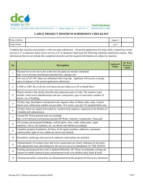
<strong>LARGE</strong> <strong>PROJECT</strong> <strong>MINIMUM</strong> <strong>SUBMISSION</strong> <strong>CHECKLIST</strong>Project AddressProject NameSquare #Lot #Complete this checklist and include it with your plan submission. All permit applications for large utility connections (waterservices ≥ 3" in diameter and/or sewer services ≥ 8" in diameter) shall meet the following minimum submission criteria. Plansubmissions that do not include this completed checklist and the required information are subject to rejection.NoDescriptionApplicant'sInitials<strong>DC</strong> <strong>Water</strong>Reviewer'sInitials1Payment for review fee is due at the time the plans are initially submitted.http://www.dcwater.com/business/permits/fees_charges.cfm2Two sets of 24”x36” plans are submitted with a log slip. Applicant will receive a receiptupon acceptance of the permit application submission.3A PDF or TIFF file of all site civil sheets are provided on a CD or thumb drive.4Project narrative that clearly describes the proposed scope of work. The narrative mustinclude: water/sewer abandonments and new connections, type of renovation, number ofstories, use of building.5Vicinity map, description of proposed work, legend, index of sheets, date, scale, verticaldatum used, submission number are provided. If in metric, provide US standard labels also.6All plan sheets are signed and sealed by a professional engineer, registered in the District ofColumbia (all submissions).7Current <strong>DC</strong> <strong>Water</strong> general notes are included.http://www.dcwater.com/business/permits/<strong>DC</strong><strong>Water</strong>_General_Construction_Notes.pdf8All existing and proposed buildings, curb & gutter, trees, walls, utility poles, signs,manholes, valves, fire hydrants, etc. are shown and labeled accordingly.9Complete property boundaries, lot lines, lot & square numbers, addresses, easements,roadway/alley right-of-way widths are shown and labeled.10Demolition, landscape and erosion & sediment control plans are included.11Abandonments of existing water and sewer connections are clearly indicated on the planswith appropriate notes describing how the services are to be abandoned AT THE MAINS.12Existing and proposed line work is drafted differently. <strong>DC</strong> <strong>Water</strong> recommends existing sitefeatures be drafter dashed & gray and proposed work to be drafted solid, black & bold.13 All proposed utility connections are dimensioned from the property/lot line in two directions.February 2013: Minimum Submission Checklist <strong>LARGE</strong> 1 of 3
NoDescriptionApplicant'sInitials<strong>DC</strong> <strong>Water</strong>Reviewer'sInitials14The following existing and proposed utilities are shown, labeled (size, material & date ofinstallation, if available), and dimensioned from the property line:14.1 <strong>Water</strong>: mains, laterals, water meters (domestic & fire)14.2 Sanitary Sewers: mains, laterals (with flow arrows)14.3 Storm Sewers: mains, laterals (with flow arrows)14.4 Combined Sewer: mains, laterals (with flow arrows)14.5 Electric: overhead and/or underground, poles, guy wires, vaults14.6 Gas: mains, laterals, meters14.7 Communications (fiber optic, telephone, cable): overhead and/or underground,guy wires, poles, vaults15Draft of any proposed easement and/or covenant is included on the plan set.16Stationing (0+00) on both the plan and profile for all proposed water and sewer mains andlaterals has been provided.17Plans include details that are signed & sealed by a professional engineer of complicatedutility installations to document final measurements and to list all water valves, fittings,thrust blocks, etc. to be installed.18Profiles are provided for all proposed water lines 3" diameter and larger, and/or sewer lines4" diameter and larger. The profile includes the following:18.1 Existing & proposed invert and top elevations of all structures and clean-outs. Providevertical datum used.18.2 Material, size, and slope of pipe18.3 Existing & proposed ground profile18.4 Existing & proposed utility crossings (with minimum 12" vertical seperation)18.5 The horizontal scale of the profile matches the plan scale18.6 Property line & limits of public and private maintenance19Storm sewer and stormwater management design includes the following:19.1 Existing & proposed drainage divides with flow arrows19.2 Time of concentration, runoff C value, and 15-year runoff rate19.3 Pipe capacity, inlet computations, and hydraulic grade line computations(with 15-year hydraulic grade line plotted on the profile)19.4 Stormwater management narrative19.5 Stormwater management detailsFebruary 2013: Minimum Submission Checklist <strong>LARGE</strong> 2 of 3
NoDescriptionApplicant'sInitials<strong>DC</strong> <strong>Water</strong>Reviewer'sInitials20<strong>DC</strong> <strong>Water</strong> standard forms and details are completed, signed and included in the plan set:20.1 Hydrant flow test results (valid for one (1) year from date of test)20.2 Meter sizing worksheets (including both domestic and fire demands)20.3 Backflow preventer form (for both domestic and fire services)20.4 Booster pump data form (if applicable)20.5 Letters requesting variances (i.e. domestic meter inside building, fire detector checkassembly outside building, public manhole within driveway entrance).20.6 Plans conform to the <strong>DC</strong> WASA Project Design Manual Volume 3 InfrastructureDesign July 31, 2001 and <strong>DC</strong> WASA Standard Details & Design Guidelines January, 2008.21Structural design calculations are included (if applicable), i.e. thrust blocking on water lineslarger than 12-inch diameter, pile supported utilities, installation that imparts additional loadon an existing facility, utility installation that is deeper than the standard depth, cast-in-placesewer manholes, etc.22For re-submittals, a comment response letter is included stating both the comment from thereviewer and a response from the engineer.23If you are requesting to reuse the existing storm and/or sanitary lateral, a closed circuittelevision inspection of the pipe(s) must be included for review by <strong>DC</strong> <strong>Water</strong>. Provide a siteplan along with the CCTV video to identify the location of these laterals with relationship tothe roadway and building.24Per <strong>DC</strong> <strong>Water</strong> details W-80.01 and S-80.01, the proposed water meter, curb cock, and sewerclean-out are located in public space and not in driveways, under walls or stairs.25If the project includes a water or sewer main replacement, the plans clearly identify alladjacent properties to be reconnected to the new main. The plans include full limits ofdisturbance from the public main to the property line, address, lot & square of propertiesaffected, size & material of existing service.26For domestic meters to be installed inside the building (exception approved by Director)provide a detailed floor and piping plan with the following information: walls, pipes, valves,bypass, other utilities, access, floor drains and clearance.27The sewer plumbing system is in compliance with Section 715 of the 2006 InternationalPlumbing Code. Backwater valves are installed where the plumbing fixture elevations arebelow the elevation of the manhole cover of the next upstream manhole in the public sewer.For all other fixtures above the upstream manhole rim, the applicant has provided elevationinformation to support no requirement for a backwater valve.February 2013: Minimum Submission Checklist <strong>LARGE</strong> 3 of 3