Critical chloride content in reinforced concrete - Sintef
Critical chloride content in reinforced concrete - Sintef
Critical chloride content in reinforced concrete - Sintef

Create successful ePaper yourself
Turn your PDF publications into a flip-book with our unique Google optimized e-Paper software.
COIN Workshop on “critical <strong>chloride</strong> <strong>content</strong>” <strong>in</strong> re<strong>in</strong>forced <strong>concrete</strong>PrefaceThis workshop has been carried out with<strong>in</strong> COIN - Concrete Innovation Centre - one ofpresently 14 Centres for Research based Innovation (CRI), which is an <strong>in</strong>itiative by theResearch Council of Norway. The ma<strong>in</strong> objective for the CRIs is to enhance the capability ofthe bus<strong>in</strong>ess sector to <strong>in</strong>novate by focus<strong>in</strong>g on long-term research based on forg<strong>in</strong>g closealliances between research-<strong>in</strong>tensive enterprises and prom<strong>in</strong>ent research groups.The vision of COIN is creation of more attractive <strong>concrete</strong> build<strong>in</strong>gs and constructions.Attractiveness implies aesthetics, functionality, susta<strong>in</strong>ability, energy efficiency, <strong>in</strong>doorclimate, <strong>in</strong>dustrialized construction, improved work environment, and cost efficiency dur<strong>in</strong>gthe whole service life. The primary goal is to fulfil this vision by br<strong>in</strong>g<strong>in</strong>g the development amajor leap forward by more fundamental understand<strong>in</strong>g of the mechanisms <strong>in</strong> order todevelop advanced materials, efficient construction techniques and new design conceptscomb<strong>in</strong>ed with more environmentally friendly material production.The corporate partners are lead<strong>in</strong>g mult<strong>in</strong>ational companies <strong>in</strong> the cement and build<strong>in</strong>g<strong>in</strong>dustry and the aim of COIN is to <strong>in</strong>crease their value creation and strengthen their researchactivities <strong>in</strong> Norway. Our over-all ambition is to establish COIN as the display w<strong>in</strong>dow for<strong>concrete</strong> <strong>in</strong>novation <strong>in</strong> Europe.About 25 researchers from SINTEF (host), the Norwegian University of Science andTechnology - NTNU (research partner) and <strong>in</strong>dustry partners, 15 - 20 PhD-students, 5 - 10MSc-students every year and a number of <strong>in</strong>ternational guest researchers, work on presently5 projects:• Advanced cement<strong>in</strong>g materials and admixtures• Improved construction techniques• Innovative construction concepts• Operational service life design• Energy efficiency and comfort of <strong>concrete</strong> structuresCOIN has presently a budget of NOK 200 mill over 8 years (from 2007), and is f<strong>in</strong>anced bythe Research Council of Norway (approx. 40 %), <strong>in</strong>dustrial partners (approx 45 %) and bySINTEF Build<strong>in</strong>g and Infrastructure and NTNU (<strong>in</strong> all approx 15 %).For more <strong>in</strong>formation, see www.co<strong>in</strong>web.noTor Arne HammerCentre Manager3
COIN Workshop on “critical <strong>chloride</strong> <strong>content</strong>” <strong>in</strong> re<strong>in</strong>forced <strong>concrete</strong>6
COIN Workshop on “critical <strong>chloride</strong> <strong>content</strong>” <strong>in</strong> re<strong>in</strong>forced <strong>concrete</strong>IntroductionThe COIN workshop was held <strong>in</strong> June 5–6, 2008, at the Norwegian University of Scienceand Technology NTNU <strong>in</strong> Trondheim, Norway. It focused on critical <strong>chloride</strong> <strong>content</strong>(<strong>chloride</strong> threshold value) <strong>in</strong> re<strong>in</strong>forced <strong>concrete</strong> with emphasis on techniques fordeterm<strong>in</strong><strong>in</strong>g critical <strong>chloride</strong> <strong>content</strong>s and its relevance for practice.This report <strong>in</strong>cludes the abstracts and the foils presented at the workshop.The programmes for the two days and the list of participants are shown below.Workshop programme:Day 1, Thursday 5 June, 200808.00 – 08.50 Registration0850 – 09.00 Welcome by Tor Arne Hammer (Project Manager of COIN)09.00 – 10.00 Chris Page: Importance of the steel-<strong>concrete</strong> <strong>in</strong>terface with regardto corrosion <strong>in</strong>itiation <strong>in</strong> the presence of <strong>chloride</strong>.Discussion10.00 – 11.00 Josef Tritthart: Pore solution of <strong>concrete</strong>. The equilibrium ofbound and freeDiscussion11.00 – 12.00 Luca Bertol<strong>in</strong>i: Depassivation of steel <strong>in</strong> case of pitt<strong>in</strong>g corrosion -detection techniques for laboratory studies.Discussion12.00 – 13.00 Lunch13.00 – 14.00 Maria Cruz Alonso: Chloride threshold values <strong>in</strong> the literature.Discussion14.00 – 15.00 Bernhard Elsener: Chloride sensors <strong>in</strong> <strong>concrete</strong> - accuracy and longterm stability.Discussion15.00 – 16.00 Ueli Angst: Laboratory experiments for detect<strong>in</strong>g critical <strong>chloride</strong><strong>content</strong> <strong>in</strong> re<strong>in</strong>forced <strong>concrete</strong>.Discussion16.00 – 17.00 Rob Polder: Relationship between electrical <strong>concrete</strong> resistivity andcritical <strong>chloride</strong> <strong>content</strong>.Discussion20.00 D<strong>in</strong>ner at Grenaderen restaurantDay 2, Friday 6 June,200809.00 – 10.00 Joost Gulikers: <strong>Critical</strong> considerations regard<strong>in</strong>g laboratoryresearch on the critical <strong>chloride</strong> <strong>content</strong> <strong>in</strong> re<strong>in</strong>forced <strong>concrete</strong>.Discussion7
COIN Workshop on “critical <strong>chloride</strong> <strong>content</strong>” <strong>in</strong> re<strong>in</strong>forced <strong>concrete</strong>10.00 – 11.00 Gro Markeset: <strong>Critical</strong> <strong>chloride</strong> <strong>content</strong> and its <strong>in</strong>fluence on servicelife predictions.Discussion11.00 – 12.00 Tang Lup<strong>in</strong>g: A field study of critical <strong>chloride</strong> <strong>content</strong> <strong>in</strong> re<strong>in</strong>forced<strong>concrete</strong> with blended b<strong>in</strong>derDiscussion12.00 – 13.00 Lunch <strong>in</strong> Realfagsbygget13.00 – 14.00 John Miller: Reference material for calibrat<strong>in</strong>g <strong>chloride</strong> analysis ofhardened <strong>concrete</strong>Discussion14.00 – 15.00 Jens Frederiksen: On the need for more precise threshold values for<strong>chloride</strong> <strong>in</strong>itiated corrosion <strong>in</strong> design, repair and ma<strong>in</strong>tenance ofre<strong>in</strong>forced <strong>concrete</strong> structures - a consultant's view.Discussion15.00 Clos<strong>in</strong>g the workshopThe workshop participants:Last name First name E mail Organization:Kjellsen Knut Ose knut.kjellsen@norcem.no Norcem ASGulikers Joost joost.gulikers@rws.nl Rijkswaterstaat BouwdienstHelland Ste<strong>in</strong>ar ste<strong>in</strong>ar.helland@skanska.no Skanska Norge ASMiller John B. millcon@onl<strong>in</strong>e.no Millab Consult ASTritthart Josef tritthart@tugrat.at Graz, University of TechnologyFredriksen Jens Mejer jmf@alectia.com Alectia ASAlonso Maria Cruz mcalonso@ietcc.csi.esInstituto de Ciencias de laConstrucción Eduardo TorrojaBertol<strong>in</strong>i Luca luca.bertol<strong>in</strong>i@polimi.it Politecnico de MilanoPage Chris c.l.page@bham.ac.uk University of Birm<strong>in</strong>ghamPolder Rob rob.polder@tno.nl TNO BouwElsener Bernhard elsener@ethz.ch ETH HöngerbergNygaard Peter pvn@force.dk FORCE TechnologyManera Marco mmanera@mgtpatents.com MGT patentsRebolledo Nuria nuriare@ietcc.csi.esInstituto de Ciencias de laConstrucción Eduardo TorrojaSørensen Birgit biso@cowi.dk Cowi ASLup<strong>in</strong>g Tang tang.lup<strong>in</strong>g@sp.se CBI Betong<strong>in</strong>stitutetBoubitsas Dimitrios dimitrios.boubitsas@sp.se CBI Betong<strong>in</strong>stitutetMarkeset Gro gro.markeset@s<strong>in</strong>tef.no SINTEFVennesland Øyste<strong>in</strong> oyste<strong>in</strong>.vennesland@ntnu.no NTNUHammer Tor Arne tor.hammer@s<strong>in</strong>tef.no SINTEFAngst Ueli ueli.angst@ntnu.no NTNULarsen Claus K. claus.larsen@vegvesen.no Staten vegvesenØstvik Jan Magnus jan-magnus.ostvik@vegvesen.no Statens vegvesen8
COIN Workshop on “critical <strong>chloride</strong> <strong>content</strong>” <strong>in</strong> re<strong>in</strong>forced <strong>concrete</strong>1 Initiation of <strong>chloride</strong>-<strong>in</strong>duced corrosion“Initiation on Chloride-<strong>in</strong>duced Corrosion of Steel <strong>in</strong>Concrete: Role of the Interfacial Zone”Chris L. PageUniversity of Birm<strong>in</strong>gham9
COIN Workshop on “critical <strong>chloride</strong> <strong>content</strong>” <strong>in</strong> re<strong>in</strong>forced <strong>concrete</strong>10
COIN Workshop on “<strong>Critical</strong> <strong>chloride</strong> <strong>content</strong> <strong>in</strong> re<strong>in</strong>forced <strong>concrete</strong>”, Trondheim, 5-6 June 2008Initiation of Chloride-<strong>in</strong>duced Corrosion of Steel <strong>in</strong> Concrete:Role of the Interfacial ZoneC L PageUniversity of Birm<strong>in</strong>ghamGiven that some of the basic phenomena associated with the passivity of ultrapureiron <strong>in</strong> aqueous solutions of NaOH and KOH are still <strong>in</strong>completely understood (1,2),it would be surpris<strong>in</strong>g, to say the least, if the same were not true for aspects of theelectrochemical behaviour of re<strong>in</strong>forc<strong>in</strong>g and prestress<strong>in</strong>g steels <strong>in</strong> <strong>concrete</strong>. One of themany reasons for this is that pre-exist<strong>in</strong>g layers of mill-scale or rust, which may or maynot be present on the metal surface prior to its embedment <strong>in</strong> a <strong>concrete</strong> structure, areliable to affect the ease with which passivation and depassivation will occur, as has beennoted by many researchers (3-12). Such layers of mixed oxides and hydrated oxides ofiron, whose natures and thicknesses depend on features of the alloy composition, themanufactur<strong>in</strong>g process and the vagaries of storage, are notoriously variable and difficultto characterise. Fortunately, however, the high pH values of the pore solutions formeddur<strong>in</strong>g cement hydration (13) are normally sufficient to <strong>in</strong>duce passivation of embeddedsteel, as is evident from the noble potentials (> 200 mV SCE ) that are typically observed forre<strong>in</strong>forc<strong>in</strong>g bars embedded <strong>in</strong> atmospherically exposed <strong>concrete</strong> structures which havenot become significantly contam<strong>in</strong>ated by <strong>chloride</strong>s or carbonation.When study<strong>in</strong>g the <strong>in</strong>fluence of variables, related to <strong>concrete</strong> composition,methods of manufacture, environmental exposure conditions etc, that affect the corrosionbehaviour of steel <strong>in</strong> <strong>concrete</strong> exposed to <strong>chloride</strong> <strong>in</strong>gress, it has usually been necessaryto start by clean<strong>in</strong>g the metal surface because particular samples of bars <strong>in</strong> their ‘asreceived’or ‘pre-rusted’ conditions are not representative or reproducible. For this reason,laboratory research has ma<strong>in</strong>ly been undertaken with steel bars, which have been cleanedby grit blast<strong>in</strong>g or similar methods and then degreased and stored <strong>in</strong> dry air until use. Anexample of this k<strong>in</strong>d of <strong>in</strong>vestigation, performed at Aston University (6,14), exam<strong>in</strong>edrelationships between the corrosion responses of embedded steel bars and pore solutioncompositional features (determ<strong>in</strong>ed at various depths correspond<strong>in</strong>g to the bars) with<strong>in</strong>Portland cement <strong>concrete</strong> slabs of different types that were exposed for 6, 12 and 24months to external <strong>chloride</strong> solutions (5% NaCl). The ma<strong>in</strong> objective of the work was toelucidate the circumstances lead<strong>in</strong>g to depassivation of steel that had been allowed toform a stable passive layer over a long period <strong>in</strong> well-made laboratory specimens of<strong>concrete</strong>.The results demonstrated that, <strong>in</strong> <strong>concrete</strong> specimens, which were as free aspossible from macroscopic defects (voids, cracks, crevices etc) at the surfaces ofembedded bars, no significant corrosion of passive steel was <strong>in</strong>duced until theconcentration of free <strong>chloride</strong> ions <strong>in</strong> the pore solution near the bars exceeded that of freehydroxyl ions by a factor of at least 3 times and, <strong>in</strong> some cases, as much as 20 times.These ratios of free [Cl - ]/[OH - ] were far higher than those that had previously been found(15,16) to cause depassivation of steel <strong>in</strong> bulk alkal<strong>in</strong>e electrolytes of the same pH rangeas existed with<strong>in</strong> the <strong>concrete</strong> at depths correspond<strong>in</strong>g to the bars when depassivation was11
ecorded. This difference was believed to be due ma<strong>in</strong>ly to the buffer<strong>in</strong>g effect of a layerof cement hydration products deposited <strong>in</strong> <strong>in</strong>timate contact with the passive film on theembedded steel. It was concluded that a significant cause of the much lower tolerance to<strong>chloride</strong> exhibited by steel bars <strong>in</strong> re<strong>in</strong>forced <strong>concrete</strong> structures exposed to deic<strong>in</strong>g salt(17) was the presence of macroscopic defects which disrupt the <strong>in</strong>tegrity of the layer ofhydration products deposited at the steel-<strong>concrete</strong> <strong>in</strong>terface. Another contributory factorwas suggested to be the variable surface condition of the steel re<strong>in</strong>forcement prior to itsembedment <strong>in</strong> site-produced <strong>concrete</strong> (6).More recently, researchers at the University of South Florida (8) have comparedthe behaviour of steel bars, which were either sandblasted or not cleaned prior to be<strong>in</strong>gimmersed <strong>in</strong> bulk aqueous solutions ma<strong>in</strong>ta<strong>in</strong>ed at various constant pH values (12.6, 13.3and 13.6). After passivation had been <strong>in</strong>duced, <strong>in</strong>creased concentrations of <strong>chloride</strong> wereprogressively <strong>in</strong>troduced <strong>in</strong>to the solutions and it was shown that: (i) the sandblasted steelbars were more tolerant to <strong>chloride</strong> than the mill-scaled or pre-rusted bars, (ii) the criticalratios of free [Cl - ]/[OH - ], at which depassivation of the bars was observed, <strong>in</strong>creased with<strong>in</strong>creas<strong>in</strong>g solution pH value (be<strong>in</strong>g > 1 at pH 13.6). These resultsare relevant to re<strong>in</strong>forced <strong>concrete</strong> exposed under conditions where <strong>chloride</strong> <strong>in</strong>gress is notaccompanied by significant reduction <strong>in</strong> the pore solution pH. They do not, however,account for the very high ratios of free [Cl - ]/[OH - ] that were found around many of thepassive steel bars <strong>in</strong> the earlier work at Aston University. While the bulk <strong>in</strong>ternal pHvalues of the Aston specimens were orig<strong>in</strong>ally <strong>in</strong> the expected range for Portland cement<strong>concrete</strong>s of w/c 0.5 (13.6 > pH > 13.3) the leach<strong>in</strong>g of free hydroxyl ions thataccompanied <strong>chloride</strong> <strong>in</strong>gress was found to have reduced the pH to about 12.5 andresulted <strong>in</strong> free [Cl - ]/[OH - ] ratios > 10 at depths correspond<strong>in</strong>g to several of the bars thatwere found to be ma<strong>in</strong>ta<strong>in</strong>ed <strong>in</strong> a passive condition (6,14).That the high tolerance to <strong>chloride</strong>-<strong>in</strong>duced pitt<strong>in</strong>g sometimes exhibited by steel<strong>in</strong> <strong>concrete</strong> exposed to the <strong>in</strong>gress of <strong>chloride</strong> ion might be due, <strong>in</strong> part, to the chemicalbuffer<strong>in</strong>g action of solid hydration products deposited <strong>in</strong> the <strong>in</strong>terfacial zone was firstsuggested as long ago as 1975 (18) and discussed <strong>in</strong> further detail <strong>in</strong> subsequent papers ofsimilar v<strong>in</strong>tage (19,20). In the orig<strong>in</strong>al publication (18) it was noted that previous workershad found that voids at the <strong>in</strong>terface were almost <strong>in</strong>variably the positions at whichcorrosion of steel re<strong>in</strong>forcement and prestress<strong>in</strong>g tendons takes place (21) and thatmeasures which promote homogeneity of the <strong>in</strong>terfacial zone, such as application of aslurry of neat Portland cement paste to the steel before embedd<strong>in</strong>g it <strong>in</strong> <strong>concrete</strong>, wereknown to be effective <strong>in</strong> reduc<strong>in</strong>g the risk of <strong>chloride</strong>-<strong>in</strong>duced corrosion (22). At thattime, pla<strong>in</strong> Portland cements were generally used for structural applications <strong>in</strong> sal<strong>in</strong>eenvironments and rather limited evidence was available concern<strong>in</strong>g microstructuralfeatures of <strong>in</strong>terfacial zones with embedded steel, the most relevant contribution cited <strong>in</strong>(18) be<strong>in</strong>g a paper by Moreau <strong>in</strong> which scann<strong>in</strong>g electron microscopy (SEM) had beenused <strong>in</strong> secondary electron imag<strong>in</strong>g mode to exam<strong>in</strong>e fracture surfaces of <strong>in</strong>terfacesformed above and below horizontal re<strong>in</strong>forc<strong>in</strong>g bars (23). Moreau’s work, which waspublished <strong>in</strong> French, showed that segregated portlandite (CH) crystals of vary<strong>in</strong>gmorphology were a major component of the <strong>in</strong>terfacial regions and demonstrated that,when compared with the relatively compact layers of hydration products deposited overthe upper surfaces of the bars, the undersides were characterised by more porous, open-12
textured zones with much larger s<strong>in</strong>gle crystals of CH that had grown <strong>in</strong> the relativelythick solution-filled spaces formed by collection of bleed water beneath the bars.Several subsequent <strong>in</strong>vestigations <strong>in</strong>volv<strong>in</strong>g the use of secondary electronimag<strong>in</strong>g SEM have confirmed the presence of segregated CH-enriched <strong>in</strong>terfacial zonesat clean mild steel or sta<strong>in</strong>less steel fracture surfaces that had been <strong>in</strong> contact withPortland cement pastes, mortars and <strong>concrete</strong>s (24-34) though the morphology and degreeof orientation of the CH have been found to vary, as has the distribution of C-S-H andother hydrate phases that have been identified. These different observations seem tosuggest that Portland cements of differ<strong>in</strong>g compositions, which give rise to significantdifferences <strong>in</strong> the early development of their pore solution chemistry (13), may formsomewhat dist<strong>in</strong>ct sequences of solid hydration products via the through-solution routesthat are generally believed to give rise to early-stage microstructural development at<strong>in</strong>terfaces. Until recently, only very limited studies of <strong>in</strong>terfacial zones formed at precorrodedre<strong>in</strong>forc<strong>in</strong>g steel appear to have been reported (35,36), ma<strong>in</strong>ly no doubt becauseof the difficulties <strong>in</strong>volved <strong>in</strong> produc<strong>in</strong>g the required steel substrates with wellcharacterisedsurfaces that are adequately reproducible and representative.Although the exam<strong>in</strong>ation of simply debonded surfaces by SEM is a usefulmethod for qualitative characterisation of steel/<strong>concrete</strong> <strong>in</strong>terfaces, the approach is notcapable of provid<strong>in</strong>g quantitative compositional data for reasons that have been discussed<strong>in</strong> relation to the study of aggregate/<strong>concrete</strong> <strong>in</strong>terfaces (37). Production of polishedsections cut perpendicular to the <strong>in</strong>terfaces concerned is necessary for this purpose andthese sections can be analysed at moderately high resolution by means of back scatteredelectron imag<strong>in</strong>g SEM. There are, however, problems of specimen preparation that mustbe avoided as the surfaces concerned have to go through a number of potentiallydamag<strong>in</strong>g processes (viz. dry<strong>in</strong>g, evacuation and res<strong>in</strong> impregnation followed by severalstages of mechanical polish<strong>in</strong>g) throughout which the possibility of <strong>in</strong>troduc<strong>in</strong>g artefactsexists. Research undertaken at the University of Leeds, has attempted to overcome someof these experimental problems and a recent paper (38) has provided quantitative dataderived from a back scattered electron imag<strong>in</strong>g SEM study of <strong>in</strong>terfaces formed between<strong>concrete</strong> made from a particular ord<strong>in</strong>ary Portland cement and 9mm diameter ribbedre<strong>in</strong>forc<strong>in</strong>g bars that were embedded vertically or horizontally. Prior to embedment, thesurface of the steel was either ‘as-received’ (with rust and millscale present) or, <strong>in</strong> somecases, cleaned by wire brush<strong>in</strong>g. Among other th<strong>in</strong>gs, the results reported appear to showthat, for the particular materials and conditions studied: (i) vertical steel bars had<strong>in</strong>terfacial zones of higher CH <strong>content</strong> and higher porosity than the bulk cement matrix;(ii) for horizontal bars marked differences between the upper and lower <strong>in</strong>terfaces werefound with higher porosity on the undersides, thus confirm<strong>in</strong>g the observations ofMoreau (23); (iii) cleaned steel bars had higher levels of CH at the <strong>in</strong>terface thanuncleaned bars after long periods of embedment.Some rema<strong>in</strong><strong>in</strong>g problems of specimen preparation for quantitative analysis byback scattered electron imag<strong>in</strong>g SEM probably need further consideration if efforts are tobe made to resolve the detailed effects of cement compositional variables on <strong>in</strong>terfacialzone microstructure. This may be of some <strong>in</strong>terest <strong>in</strong> view of the <strong>in</strong>creas<strong>in</strong>g use nowbe<strong>in</strong>g made of cements with high levels of supplementary cementitious materials (SCMs)that react with CH. If the aim is to develop new cements, which can offer enhancedprotection to embedded steel under conditions of exposure to <strong>chloride</strong>s, there may have to13
COIN Workshop on “critical <strong>chloride</strong> <strong>content</strong>” <strong>in</strong> re<strong>in</strong>forced <strong>concrete</strong>18
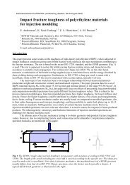
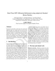
COIN Workshop on “<strong>Critical</strong> <strong>chloride</strong> <strong>content</strong> <strong>in</strong> re<strong>in</strong>forced <strong>concrete</strong>”, Trondheim, 5-6 June 2008Pore solution of <strong>concrete</strong>: The equilibrium of bound and free <strong>chloride</strong>J. Tritthart1. IntroductionIt was <strong>in</strong> the second half of the fifties of the last century that it became apparent that <strong>chloride</strong>smay trigger corrosion <strong>in</strong> the steel re<strong>in</strong>forcements of <strong>concrete</strong>. However, dur<strong>in</strong>g subsequent<strong>in</strong>vestigations carried out <strong>in</strong> order to determ<strong>in</strong>e which <strong>chloride</strong> <strong>content</strong> is harmless and which isnot, greatly differ<strong>in</strong>g limit values were obta<strong>in</strong>ed. In Austria, a limit value of 0.4 % <strong>chloride</strong> relatedto the cement <strong>content</strong> of <strong>concrete</strong> was <strong>in</strong>troduced as an assessment criterion. This amount of<strong>chloride</strong> was considered to be harmless because based on test results it could be concludedthat cement is able to b<strong>in</strong>d “firmly and permanently” up to 0.4% of <strong>chloride</strong> [1]. The author of thispaper was alerted to the question of <strong>chloride</strong>-<strong>in</strong>duced corrosion of re<strong>in</strong>forced <strong>concrete</strong> <strong>in</strong> thesecond half of the seventies. Checks on road bridges <strong>in</strong> Austria <strong>in</strong> which the author was <strong>in</strong>volved(such checks were performed more and more frequently <strong>in</strong> the aftermath of the collapse ofVienna’s Reichsbrücke <strong>in</strong> 1976) quite often showed areas of clearly enhanced <strong>chloride</strong> <strong>content</strong>but no signs of steel corrosion. This prompted the author to start <strong>in</strong>vestigations of his own.The threshold value of 0.4% and all the other threshold values of cement-based materials found<strong>in</strong> literature were based on the total <strong>chloride</strong> <strong>content</strong> of the <strong>concrete</strong> related to the cement mass.As only the unbound <strong>chloride</strong> which rema<strong>in</strong>s dissolved <strong>in</strong> the pore solution can <strong>in</strong>teract with theprotective layer on the steel surface, possibly destroy it and <strong>in</strong>itiate corrosion, the <strong>in</strong>vestigationsfocused on the <strong>chloride</strong> concentration of the pore solution after b<strong>in</strong>d<strong>in</strong>g and the factors of<strong>in</strong>fluence. For this, pore solution was pressed out of hardened cement pastes which wereprepared i) with the addition of a <strong>chloride</strong> salt or ii) free of <strong>chloride</strong> but the <strong>chloride</strong> was addedsubsequently via diffusion. That way it should be found out whether there were differences <strong>in</strong><strong>chloride</strong> b<strong>in</strong>d<strong>in</strong>g between samples which conta<strong>in</strong>ed <strong>chloride</strong> from the very beg<strong>in</strong>n<strong>in</strong>g andsamples <strong>in</strong>to which <strong>chloride</strong> penetrated after harden<strong>in</strong>g.2. Chloride b<strong>in</strong>d<strong>in</strong>g <strong>in</strong> cement when added dur<strong>in</strong>g sample preparationFor sample preparation, the <strong>chloride</strong> salt was dissolved <strong>in</strong> the mix<strong>in</strong>g water before mix<strong>in</strong>g. Thefresh pastes, which had been mixed with a spoon, were filled <strong>in</strong>to conta<strong>in</strong>ers supported byframes that could be turned. After fill<strong>in</strong>g, the conta<strong>in</strong>ers were tightly closed and tuned over nightto avoid sedimentation. Then the samples were wrapped <strong>in</strong> plastic bags and stored at 20°C untiltest<strong>in</strong>g. Then, pore solution was partly squeezed out and analysed.Cl - -concentration <strong>in</strong> the poresolution (ppm)40000CEM I + NaClCEM II/B-S + NaCl30000C3A-free + NaClCEM I; CaCl220000CEM II/B-S; CaCl2C3A-free; CaCl21000000.0 0.4 0.6 0.8 1.0 1.5 2.0Total <strong>chloride</strong> <strong>content</strong> (% ww cement)19
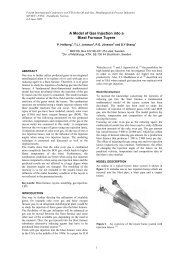
Figure 1:Cl - -concentration of the pore solution versus total <strong>chloride</strong> <strong>content</strong>Figure 1 shows the <strong>in</strong>fluence of total <strong>chloride</strong> <strong>content</strong>. It can be seen that the <strong>chloride</strong>concentration <strong>in</strong> the pore solution <strong>in</strong>creased cont<strong>in</strong>uously with <strong>in</strong>creas<strong>in</strong>g total <strong>chloride</strong> <strong>content</strong>and that there were differences depend<strong>in</strong>g on the type of cement as well as on the <strong>chloride</strong> saltadded. Most <strong>chloride</strong> was bound by the CEM II/B-S followed by the CEM I and least <strong>chloride</strong>was bound by the C 3 A-free sulphate-resist<strong>in</strong>g cement. The cont<strong>in</strong>uous <strong>in</strong>crease of the Cl - -concentration <strong>in</strong> the liquid phase <strong>in</strong>dicates that besides chemical b<strong>in</strong>d<strong>in</strong>g adsorptive b<strong>in</strong>d<strong>in</strong>gtook place as well. Were only chemical b<strong>in</strong>d<strong>in</strong>g to occur, the equilibrial Cl - -concentration of thepore water should have rema<strong>in</strong>ed relatively constant as long as cl<strong>in</strong>ker phases such C 3 A, whichare able to b<strong>in</strong>d the <strong>chloride</strong> chemically, were present and would <strong>in</strong>crease rapidly if thesecomponents reacted. To verify the <strong>in</strong>fluence of C 3 A available for <strong>chloride</strong> b<strong>in</strong>d<strong>in</strong>g, the sulphate<strong>content</strong> of cement was <strong>in</strong>creased <strong>in</strong> various steps. The more C 3 A reacted with the sulphate andformed ettr<strong>in</strong>gite (“trisulfate”; 3CaO.Al 2 O 3 .3CaSO 4 .32H 2 O) the more gypsum was added and theless C 3 A rema<strong>in</strong>ed available for <strong>chloride</strong> b<strong>in</strong>d<strong>in</strong>g. As expected, the Cl - -concentration of the poresolution <strong>in</strong>creased with <strong>in</strong>creas<strong>in</strong>g sulphate <strong>content</strong> of the cement but rema<strong>in</strong>ed approx.constant from a C 3 A/SO 4 -2 -ratio of 3 upwards.Figure 1 shows furthermore that the Cl - -concentration of the pore solution was higher whenNaCl was added than when CaCl 2 was added. This is <strong>in</strong> agreement with f<strong>in</strong>d<strong>in</strong>gs described byother authors [2, 3]. However, it was surpris<strong>in</strong>g that the <strong>in</strong>fluence of the added <strong>chloride</strong> salt waseven higher than that of the type of cement. This can be expla<strong>in</strong>ed by the changes <strong>in</strong> the OH - -concentrations of the pore solution.OH - -concentration <strong>in</strong> the poresolution120009000600030000CEM I; NaClC3A-free; NaClCEM II/B-S + CaCl2CEM II/B-S; NaClCEM I + CaCl2C3A-free + CaCl20.0 0.4 0.6 0.8 1.0 1.5 2.0Total <strong>chloride</strong> <strong>content</strong> (% mm cement)Figure 2: OH - -concentration of the pore solution versus total <strong>chloride</strong> <strong>content</strong>As can be seen from Figure 2, the hydroxide concentration <strong>in</strong>creased with the use of NaCl butdecreased with CaCl 2 . The reason for the difference <strong>in</strong> OH - -concentration of the pore solutionbetween samples conta<strong>in</strong><strong>in</strong>g NaCl and CaCl 2 is that at the high pH-values of the pore solutioncalcium is <strong>in</strong>soluble (contrary to sodium) and precipitates as Ca(OH) 2 . Therefore the OH - -concentration of the pore solution is reduced the more the higher the amount of CaCl 2 [4, 5].Further studies with the use of other <strong>chloride</strong> compounds which reduce the OH - -concentration <strong>in</strong>the same way as CaCl 2 does (MaCl 2 , HCl) showed that practically the same amount of <strong>chloride</strong>was bound as was the case with CaCl 2 . When mixtures of <strong>chloride</strong> compounds were addedwhich affected the OH - -concentration of the pore solution differently (NaCl/CaCl 2 , etc.), the more<strong>chloride</strong> was bound (the less was the Cl - -concentration of the pore solution) the more the OH - -concentration decreased. The effect of the OH - -concentration of the liquid phase on <strong>chloride</strong>b<strong>in</strong>d<strong>in</strong>g was also found when the alkali <strong>content</strong> of the cement was reduced by wash<strong>in</strong>g outbefore sample preparation.20
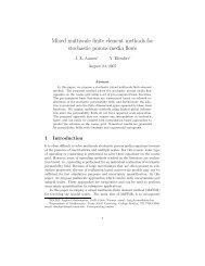
Although the found correlations strongly suggest adsorptive b<strong>in</strong>d<strong>in</strong>g of <strong>chloride</strong> and hydroxideapart from chemical b<strong>in</strong>d<strong>in</strong>g, def<strong>in</strong>ite evidence can hardly be furnished due to overlapp<strong>in</strong>gequilibria and the complex overall situation. This can expla<strong>in</strong> why the addition of silica-fume,which reduces the OH - -concentration of the liquid phase, was found to cause an <strong>in</strong>crease <strong>in</strong><strong>chloride</strong> b<strong>in</strong>d<strong>in</strong>g <strong>in</strong> one study but a decrease <strong>in</strong> another study (different cements, different typesof silica fume, etc.) [5, 6].3. Subsequently added <strong>chloride</strong>To exam<strong>in</strong>e the b<strong>in</strong>d<strong>in</strong>g of <strong>chloride</strong> added subsequently by diffusion, <strong>chloride</strong>-free cement slabsof 1 cm thickness and w/c-ratios of 0.5 and 0.7 were used [4, 5]. After 28 days of harden<strong>in</strong>g, theslabs were immersed <strong>in</strong> <strong>chloride</strong>-conta<strong>in</strong><strong>in</strong>g solutions until no further <strong>chloride</strong> uptake occurred sothat the <strong>chloride</strong> concentration was practically the same <strong>in</strong> the pore solution and <strong>in</strong> the storagesolution. The slabs were immersed <strong>in</strong> storage solutions with different OH - -concentrations,namely <strong>in</strong> saturated Ca(OH) 2 (pH-value: 12.5), 0.1 m NaOH (pH-value: 13.0) and 0.5 m NaOH(pH-value: 13.7). Five different Cl - -concentrations were used. From time to time the Cl - -concentration of the storage solution was measured and used-up <strong>chloride</strong> replenished. That waythe Cl - -concentrations were kept more or less constant over the whole test period. Pore solutionwas pressed out after about 1 year <strong>in</strong> order to be sure that a state of equilibrium had beenreached and that the composition of the pore solution had become equal to that of the storagesolution. Only then the f<strong>in</strong>al determ<strong>in</strong>ation of the total <strong>chloride</strong> <strong>content</strong> of the samples wascarried out. The results are shown <strong>in</strong> Figure 3.Total <strong>chloride</strong> <strong>content</strong> (% mm cement)1,81,51,20,90,60,301000 ppm Cl3000 ppm Cl5000 ppm Cl7000 ppm Cl10000 ppm Clw/c-0.50 w/c-0.70 w/c-0.50 w/c-0.70 w/c-0.50 w/c-0.70pH-12.5 pH-13.0 pH-13.7Figure 3:Chloride uptake of cement pastes immersed <strong>in</strong> <strong>chloride</strong> solutionsAs can be seen from Figure 3 the higher the <strong>chloride</strong> concentration of the storage solution wasthe more <strong>chloride</strong> was taken up by the hardened cement. The pH-value played a major role aswell; the higher the pH-value, the less <strong>chloride</strong> was taken up. The <strong>in</strong>fluence of the w/c-ratio onthe other hand was rather <strong>in</strong>significant - samples with a w/c-ratio of 0.7 took up slightly more<strong>chloride</strong> than the ones with a w/c-ratio of 0.5. The calculation yielded that, as <strong>in</strong> the samplesprepared with the addition of <strong>chloride</strong>, the proportion of bound <strong>chloride</strong> rema<strong>in</strong>ed practically thesame regardless of the w/c-ratio. Thus the <strong>in</strong>fluence of the w/c-ratio was almost exclusively dueto the different <strong>content</strong> of pore water <strong>in</strong> the samples.4. ConclusionsThe results showed that <strong>chloride</strong> is not bound <strong>in</strong> absolute quantities but rather <strong>in</strong> dependence onan equilibrium which is established between solids and the liquid phase. The state of equilibriumand thus the residual <strong>chloride</strong> concentration depends on the composition of the cement as wellas on the chemistry of the pore solution and <strong>in</strong> particular on its OH - -concentration.21
As regards the assessment of the corrosion risk, the results showed that the Cl - -concentration ofthe pore solution varied between samples made of the same cement and conta<strong>in</strong><strong>in</strong>g a total<strong>chloride</strong> <strong>content</strong> of 1% between 2600 ppm and 23000 ppm. Other results showed that the Cl -/OH - -ratio of the pore solution - which is often mentioned to be a better <strong>in</strong>dicator for theassessment of corrosion risk [7] - <strong>in</strong>creased at a given total <strong>chloride</strong> <strong>content</strong> with decreas<strong>in</strong>gw/c-ratio which, however, is <strong>in</strong>consistent with practical experience. These results illustrate verywell that a certa<strong>in</strong> total <strong>chloride</strong> <strong>content</strong> alone is not a suitable criterion for the assessment ofcorrosion risk.References1. W. Richartz: „Die B<strong>in</strong>dung von Chlorid bei der Zementerhärtung“ („B<strong>in</strong>d<strong>in</strong>g of <strong>chloride</strong>dur<strong>in</strong>g harden<strong>in</strong>g“), Zement-Kalk-Gips; 1969, H. 10, S. 447-456.2. P. Gunkel. „Die Zusammensetzung der flüssigen Phase erstarrender und erhärtenderZemente“ (Composition of the liquid phase of sett<strong>in</strong>g and hardenenig cements“), Beton-Information, V.1, pp 19-25, 1983.3. C. M. Hansson, Th. Fr∅lund and J. B. Markussen: “The Effect of Chloride Cation Type onthe Corrosion od Steel <strong>in</strong> Concretze by Chloride Ions”; Cement and Concrete Research, V15, pp 65-73, 1985.4. J. Tritthart: "Chloride B<strong>in</strong>d<strong>in</strong>g <strong>in</strong> Cement - II. The Influence of the HydroxideConcentration <strong>in</strong> the Pore Solution of Hardened Cement Paste on Chloride B<strong>in</strong>d<strong>in</strong>g",Cement and Concrete Research, V 19, pp 683-691, 1989.5. J. Tritthart.: "Chorid<strong>in</strong>duzierte Betonstahlkorrosion"; Schriftenreihe Straßenforschung desBMfwA, Heft 346, 117 Seiten, 40 Abbildungen, 40 Tabellen, 1988.6. C. L. Page and ∅. Vennesland: “Pore soution composition and <strong>chloride</strong> b<strong>in</strong>d<strong>in</strong>g capacity ofsiliac fume cement pastes“; Materieux et Constructions, V. 16, pp 19-25, 1983.7. D. A. Hausmann. „Steel corrosion <strong>in</strong> <strong>concrete</strong>“, Materials Protection, November 1967, pp.19-23.22
Graz, University of TechnologyPore solution of <strong>concrete</strong>The equilibrium of bound and free <strong>chloride</strong>J. Tritthart Trondheim 05-06 June 2008Graz, University of TechnologyJ. Tritthart Trondheim 05-06 June 2008231
Graz, University of TechnologyJ. Tritthart Trondheim 05-06 June 2008Graz, University of TechnologyJ. Tritthart Trondheim 05-06 June 2008242
Graz, University of TechnologyJ. Tritthart Trondheim 05-06 June 2008Graz, University of TechnologyJ. Tritthart Trondheim 05-06 June 2008253
Graz, University of TechnologyJ. Tritthart Trondheim 05-06 June 2008Graz, University of TechnologyJ. Tritthart Trondheim 05-06 June 2008264
Graz, University of TechnologyJ. Tritthart Trondheim 05-06 June 2008Graz, University of TechnologyJ. Tritthart Trondheim 05-06 June 2008275
Graz, University of Technology1. 3CaO.Al 2 O 3 (C 3 A) + 3CaSO 4 + 32H 2 O 3CaO.Al 2 O 3 . 3CaSO 4 .32H 2 O(Ettr<strong>in</strong>gite; “Trisulfate”)2. 3CaO.Al 2 O 3 + CaCl 2 + 10H 2 O 3CaO.Al 2 O 3 .CaCl 2 .10H 2 O (Friedel salt)3. 3CaO.Al 2 O 3 . 3CaSO 4 .32 H 2 O (Ettr<strong>in</strong>gite) + 2[3CaO.Al 2 O 3 ] 3[3CaO.Al 2 O 3. CaSO 4 .12 H 2 O] (Monosulfate)J. Tritthart Trondheim 05-06 June 2008Graz, University of TechnologyThreshold values (empirically;; total chlorid)Related to mass of <strong>concrete</strong>------approx. 1 lb Cl - /yd³ (= approx. 0,59 kgCl - /m³; = ca. 0,02%)Related to mass of cement2% CaCl 2 (~ 1,3 Cl - ) at a concereteporosity of max. 9,5 Vol-% and am<strong>in</strong>. Cover of ≥1,5 cm0,2% Cl -------authorTomek und Vavr<strong>in</strong>(1961)Clear & Hay (1973)Stratfull et al(1975)Stewart (1975)500 ppm Cl - Lukas (1980)0,028% Cl - at 330 kg PC/m³ and a watersoluble Cl - -<strong>content</strong> of 75%;0,051% Cl - at 390 kg PC/m³ and a watersoluble. Cl - -<strong>content</strong> of 50%------------2% CaCl 2 .2 H 2 O (=~1,3% Cl - ; atdense <strong>concrete</strong>; otherwise less)0,4% Cl -1,0% - 1,5% Cl - (at dense <strong>concrete</strong>;otherwise less)OECD-RoadResearch Group(1976)Work<strong>in</strong>g group„Monoliet“ (1976)Everett et al (1980)J. Tritthart Trondheim 05-06 June 2008286
Graz, University of Technologycritical Cl - -concentrationand Cl - /OH - - ratioalkal<strong>in</strong>e solutions<strong>concrete</strong>/ mortarauthor
Graz, University of TechnologyCl - -concentration <strong>in</strong> thepore solution (ppm)12.00010.0008.0006.0004.0002.0000CEM I; NaClCEM II/B-S; NaClsulfate resistant; NaClCEM I; CaCl2CEM II/B-S; CaCl2sulfate resistant; CaCl20 25 50 75 100 125 150age of samles (days)J. Tritthart Trondheim 05-06 June 2008Graz, University of TechnologyCl - -concentration <strong>in</strong> the poresolution (ppm)40000300002000010000CEM I; NaClCEM II/B-S; NaClC3A-free; NaClCEM I; CaCl2CEM II/B-S; CaCl2C3A-free; CaCl200.0 0.4 0.6 0.8 1.0 1.5 2.0Total <strong>chloride</strong> <strong>content</strong> (% ww cement)J. Tritthart Trondheim 05-06 June 2008308
Graz, University of TechnologyCl - -concentration of the pore solution(ppm)1600012000800040000w/c: 0.60w/s: 0.600 ~0,5 ~1 ~3 ~4SO -2 4 /C 3 A-mole ratioJ. Tritthart Trondheim 05-06 June 2008Graz, University of TechnologyCl - -concentration <strong>in</strong> the poresolution (ppm)40000300002000010000CEM I; NaClCEM II/B-S; NaClC3A-free; NaClCEM I; CaCl2CEM II/B-S; CaCl2C3A-free; CaCl200.0 0.4 0.6 0.8 1.0 1.5 2.0Total <strong>chloride</strong> <strong>content</strong> (% ww cement)J. Tritthart Trondheim 05-06 June 2008319
Graz, University of TechnologyOH - -concentration <strong>in</strong> thepore solution (ppm)120009000600030000CEM I; NaClC3A-free; NaClCEM II/B-S; CaCl2CEM II/B-S; NaClCEM I; CaCl2C3A-free; CaCl20.0 0.4 0.6 0.8 1.0 1.5 2.0Total <strong>chloride</strong> <strong>content</strong> (% mm cement)J. Tritthart Trondheim 05-06 June 2008Graz, University of Technology• [Ca +2 ]. [OH - ]. [OH - ] = 5.47.10 -6• [Ca +2 ] = 5.47.10 -6 /[OH - ] 2 = 5.47.10 -6 / 10 -2 =• 5.47.10 -4 mole Ca +2 /l = ~ 22 ppmCa +2 -ions are not soluble at high pH-values andprecipitate as Ca(OH) 2J. Tritthart Trondheim 05-06 June 20083210
Graz, University of Technology14000Concentration <strong>in</strong> mg/L1200010000800060004000ClOH20000NaCl 0,25%HCl/0,75%NaCl0,5%HCl/0,5%NaClCaCl2 MgCl2 HCl 0,25%HCl/0,75%CaCl20,5%HCl/0,5%CaCl2J. Tritthart Trondheim 05-06 June 2008Graz, University of TechnologyOH - -concentration of the poresolution (ppm)16000120008000400000.4 0.5 0.6 0.7 0.8 0.9 1.0w/c-ratioNaClCaCl2J. Tritthart Trondheim 05-06 June 20083311
Graz, University of Technology25.000Cl - -concentration of the poresolution (ppm)20.00015.000NaCl10.000CaCl25.00000,4 0,5 0,6 0,7 0,8 0,9 1,0w/c-ratioJ. Tritthart Trondheim 05-06 June 20080,8Graz, University of Technology0,6NaClCl/OH-mole ratio0,40,2CaCl 23400,4 0,6 0,8 1,0w/c-ratioJ. Tritthart Trondheim 05-06 June 200812
Graz, University of TechnologyTotal Cl-<strong>content</strong> (mass-%)0,70,60,50,40,30,20,10w/c-0.50; 1000 ppm Clw/c-0.50; 3000 ppm Cl0 100 200 300 400 500Duration of storage (days)J. Tritthart Trondheim 05-06 June 2008Graz, University of TechnologyTotal <strong>chloride</strong> <strong>content</strong> (% mmcement)1,81,51,20,90,60,30w/c-0.50w/c-0.70w/c-0.50w/c-0.701000 ppm Cl3000 ppm Cl5000 ppm Cl7000 ppm Cl10000 ppm Clw/c-0.50w/c-0.70pH-12.5 pH-13.0 pH-13.7J. Tritthart Trondheim 05-06 June 20083513
Graz, University of TechnologyJ. Tritthart Trondheim 05-06 June 2008Graz, University of TechnologyJ. Tritthart Trondheim 05-06 June 20083614
Graz, University of TechnologyJ. Tritthart Trondheim 05-06 June 20083715
COIN Workshop on “critical <strong>chloride</strong> <strong>content</strong>” <strong>in</strong> re<strong>in</strong>forced <strong>concrete</strong>38
COIN Workshop on “critical <strong>chloride</strong> <strong>content</strong>” <strong>in</strong> re<strong>in</strong>forced <strong>concrete</strong>3 Depassivation of steel <strong>in</strong> case of pitt<strong>in</strong>g corrosionDepassivation of steel <strong>in</strong> case of pitt<strong>in</strong>g corrosion –Detection techniques for laboratory studiesLuca Bertol<strong>in</strong>iPolitecnico di Milano39
COIN Workshop on “critical <strong>chloride</strong> <strong>content</strong>” <strong>in</strong> re<strong>in</strong>forced <strong>concrete</strong>40
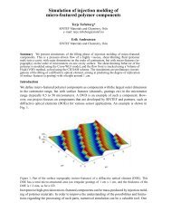
COIN Workshop on “<strong>Critical</strong> <strong>chloride</strong> <strong>content</strong> <strong>in</strong> re<strong>in</strong>forced <strong>concrete</strong>”, Trondheim, 5-6 June 2008Depassivation of steel <strong>in</strong> case of pitt<strong>in</strong>g corrosionDetection techniques for laboratory studiesLuca Bertol<strong>in</strong>iPolitecnico di Milano – Dipartimento di Chimica, Materiali e Ingegneria Chimica “G.Natta”Accord<strong>in</strong>g to Tuutti’s model, methods for the design of durability of re<strong>in</strong>forced <strong>concrete</strong> structuresexposed to mar<strong>in</strong>e environments or the action of de-ic<strong>in</strong>g salts, divide the service life <strong>in</strong>to an<strong>in</strong>itiation period, dur<strong>in</strong>g which <strong>chloride</strong> ions penetrate the <strong>concrete</strong> cover and <strong>in</strong>itiate pitt<strong>in</strong>gcorrosion, and a subsequent propagation period dur<strong>in</strong>g which corrosion leads to a limit stateaffect<strong>in</strong>g the serviceability or safety of the structure. In order to calculate the <strong>in</strong>itiation period, the<strong>chloride</strong> threshold (Cl th ), i.e. the m<strong>in</strong>imum amount of <strong>chloride</strong> ions that is required to breakdownthe passive film and <strong>in</strong>itiate pitt<strong>in</strong>g corrosion, should be def<strong>in</strong>ed. If the penetration of <strong>chloride</strong> as afunction of depth (x) and time (t) is known Cl(x,t), the <strong>chloride</strong> threshold may be measured as the<strong>chloride</strong> <strong>content</strong> detected at the depth of the bars when corrosion <strong>in</strong>itiates, i.e.:Cl th = Cl(x = c, t = t i )where c is the thickness of the <strong>concrete</strong> cover and t i is the <strong>in</strong>itiation time.The def<strong>in</strong>ition of Cl th is quite complex for several reasons. First of all, pitt<strong>in</strong>g corrosion <strong>in</strong>itiation isa stochastic phenomenon that is <strong>in</strong>fluenced by a great number of parameters. Cl th , <strong>in</strong> pr<strong>in</strong>ciple,should be def<strong>in</strong>ed through probability distributions that take <strong>in</strong>to account the effect of thoseparameters. However, such an approach would require a huge amount of experimental data which is<strong>in</strong> practice impossible to collect. Statistical analysis are available <strong>in</strong> the literature only with regardto the effect of s<strong>in</strong>gle <strong>in</strong>fluenc<strong>in</strong>g parameters. Furthermore, experimental details, such as the way<strong>chloride</strong>s are <strong>in</strong>troduced <strong>in</strong> the <strong>concrete</strong> (e.g. added to the mix<strong>in</strong>g water or penetrated by diffusionor migration) or the means of measur<strong>in</strong>g the <strong>chloride</strong> <strong>content</strong> (e.g., total acid soluble <strong>chloride</strong>sexpressed by mass of cement or free <strong>chloride</strong>s from pore expression expressed as concentration <strong>in</strong>solution) may have a large <strong>in</strong>fluence on the result<strong>in</strong>g value of the <strong>chloride</strong> threshold. The techniqueused to detect the corrosion <strong>in</strong>itiation of steel may also have a remarkable effect on the <strong>chloride</strong>threshold.S<strong>in</strong>ce there are no standardized methods for the evaluation of the <strong>chloride</strong> threshold, as well as forthe detection of corrosion <strong>in</strong>itiation, a large variety of techniques has been used by differentresearchers. Indeed, even the def<strong>in</strong>ition of the <strong>in</strong>itiation of pitt<strong>in</strong>g corrosion is not simple. In fact, an<strong>in</strong>itial phase where breakdown of the passive film alternate to repassivation at <strong>in</strong>cipient anodic sitesis followed by a permanent active corrosion stage, where susta<strong>in</strong>ed pit propagation takes place.From a practical po<strong>in</strong>t of view, it is often assumed that corrosion is <strong>in</strong>itiated when a anodic currentdensity above a certa<strong>in</strong> threshold (i.e. 1 mA/m 2 , correspond<strong>in</strong>g to roughly 1 μm/year of averagecorrosion rate) is reached.The electrochemical behaviour of steel <strong>in</strong> <strong>chloride</strong> contam<strong>in</strong>ated <strong>concrete</strong> can be described throughthe polarization curve depicted <strong>in</strong> Figure 1 (proposed by Pourbaix), that plots the anodic currentdensity (measur<strong>in</strong>g the rate of steel dissolution) as a function of the steel potential, <strong>in</strong> <strong>concrete</strong> witha given <strong>content</strong> of <strong>chloride</strong> ions. This figure shows, at low potential values, the passive range wherethe corrosion rate is negligible. Pitt<strong>in</strong>g corrosion <strong>in</strong>itiates when the potential of the steel is above apitt<strong>in</strong>g potential (E p ), which is a function of the <strong>chloride</strong> <strong>content</strong>, but also of several otherparameters (pH of the pore solution, temperature, microstructure and composition of the steel<strong>concrete</strong><strong>in</strong>terface, composition and surface f<strong>in</strong>ish<strong>in</strong>g of the steel bar, etc.). This means that, if thecorrosion potential of the passive steel (E cor ) is known, Cl th can be def<strong>in</strong>ed as the amount of <strong>chloride</strong>that br<strong>in</strong>gs about a value of E p equal to E cor .41
PotentialE pCEWEREE polPotentiostatI polSimulated <strong>concrete</strong>pore solution + Cl -log (Current density)Figure 1 – Polarization curve of steel <strong>in</strong> <strong>chloride</strong>contam<strong>in</strong>ated <strong>concrete</strong> and def<strong>in</strong>ition of thepitt<strong>in</strong>g potential E p .Figure 2 – Set up of tests <strong>in</strong> solution.This presentation deals with the possible approaches used to detect depassivation of steel <strong>in</strong> relationto the def<strong>in</strong>ition of Cl th . Firstly, tests <strong>in</strong> alkal<strong>in</strong>e solutions that simulate the <strong>concrete</strong> pore liquid willbe described. These are sometimes used to evaluate the resistance of steel to pitt<strong>in</strong>g corrosion, e.g.to compare different types of steel or the effect of preventative techniques (such as corrosion<strong>in</strong>hibitors). A steel specimen is immersed <strong>in</strong> the test solution, as depicted <strong>in</strong> Figure 2, and it isconnected to a potentiostat that can impose a polarization potential (E pol ) by means of a polarizationcurrent (I pol ). Potentiodynamic polarization tests can be used to plot the polarization curve of steelwith the aim of detect<strong>in</strong>g E p . By repeat<strong>in</strong>g the tests <strong>in</strong> solutions with vary<strong>in</strong>g concentration of<strong>chloride</strong> ions ([Cl - ]), the relationship between E p and [Cl - ] can be plotted and Cl th can beextrapolated <strong>in</strong> correspondence of a reference value of E cor . Potentiostatic polarization tests can beused, i.e. the potential of the steel is kept constant and, for <strong>in</strong>stance, <strong>chloride</strong> are added step-wiseuntil corrosion <strong>in</strong>itiation is detected by a sharp <strong>in</strong>crease <strong>in</strong> I pol .Tests on steel bars embedded <strong>in</strong> <strong>concrete</strong> (or mortar) specimens are generally considered to be moreappropriate than solution tests for a quantitative evaluation of Cl th . Specimens are exposed to<strong>chloride</strong> penetration (by pond<strong>in</strong>g, wet-dry cycles, exposure to natural mar<strong>in</strong>e environments,migration, etc.) and the <strong>chloride</strong> <strong>content</strong> is measured at the depth of the steel bars at the time whencorrosion <strong>in</strong>itiation is detected. Alternatively, <strong>chloride</strong>s can be added to the <strong>concrete</strong> mix; althoughthis approach is generally considered less appropriate, s<strong>in</strong>ce the steel is not allowed to form apassive film <strong>in</strong> <strong>chloride</strong>-free <strong>concrete</strong>, it can drastically reduce the time of test<strong>in</strong>g, especially whenimpervious <strong>concrete</strong> is considered. In this case, the <strong>chloride</strong> threshold can be detected bycomparison of specimens with higher <strong>chloride</strong> <strong>content</strong>s where corrosion <strong>in</strong>itiates and those withlower <strong>chloride</strong> <strong>content</strong>s where corrosion does not <strong>in</strong>itiate. Corrosion <strong>in</strong>itiation can be assessed byvisual <strong>in</strong>spection, i.e. when macroscopic consequences of corrosion take place (e.g. crack<strong>in</strong>g of<strong>concrete</strong>, loss of steel mass or cross section). However, corrosion can be detected only <strong>in</strong> a laterstage and, if <strong>chloride</strong>s penetrate from the surface, Cl th may be overestimated. Monitor<strong>in</strong>g ofelectrochemical parameters, usually the corrosion potential and the corrosion rate (measured bymeans of the l<strong>in</strong>ear polarization technique), are often used <strong>in</strong> order to be able to detect corrosion<strong>in</strong>itiation soon after it takes place (corrosion <strong>in</strong>itiation of steel <strong>in</strong> <strong>concrete</strong> exposed to theatmosphere is normally accompanied by a sharp decrease <strong>in</strong> the corrosion potential and <strong>in</strong>crease <strong>in</strong>the corrosion rate). Alternatively, the steel may be polarized potentiostatically and corrosion<strong>in</strong>itiation may be detected by the <strong>in</strong>crease of several orders of magnitude <strong>in</strong> the polarization current.F<strong>in</strong>ally, depassivation may also be measured with macrocell tests (by potential difference or currentflow<strong>in</strong>g between passive and active steel) .Examples of different methodology utilized for the detection of depassivation, based on the abovementioned techniques will be shown dur<strong>in</strong>g the presentation and advantages and limitations of test<strong>in</strong> solution will be addressed.42
Politecnico di MilanoDipartimento di Chimica, Materiali e Ingegneria Chimica “G. Natta”COIN Workshop on<strong>Critical</strong> <strong>chloride</strong> <strong>content</strong> <strong>in</strong> re<strong>in</strong>forced <strong>concrete</strong>Trondheim, 5-6 June 2008L.Bertol<strong>in</strong>i, Depassivation of steel <strong>in</strong> case of pitt<strong>in</strong>g corrosionDetection techniques for laboratory studiesDepassivation of steel <strong>in</strong> caseof pitt<strong>in</strong>g corrosionDetection techniques for laboratory studiesLuca Bertol<strong>in</strong>iluca.bertol<strong>in</strong>i@polimi.itChloride <strong>in</strong>duced corrosionCorrosionCorrosion limitL.Bertol<strong>in</strong>i, Depassivation of steel <strong>in</strong> case of pitt<strong>in</strong>g corrosionDetection techniques for laboratory studiest it pTime431
Chloride <strong>in</strong>duced corrosionChlorideCorrosionCorrosion limitL.Bertol<strong>in</strong>i, Depassivation of steel <strong>in</strong> case of pitt<strong>in</strong>g corrosionDetection techniques for laboratory studiesH 2 OCl -Cl(x,t 1)Coverthickness (c)ChloridethresholdDepth (x)RebarConcretet 1t it pTimeChloride <strong>in</strong>duced corrosionL.Bertol<strong>in</strong>i, Depassivation of steel <strong>in</strong> case of pitt<strong>in</strong>g corrosionDetection techniques for laboratory studiesH 2 OCl -ChlorideCl(x,t 2)Coverthickness (c)ChloridethresholdDepth (x)RebarConcreteCorrosiont 2Corrosion limitt it pTime442
Chloride <strong>in</strong>duced corrosionChlorideL.Bertol<strong>in</strong>i, Depassivation of steel <strong>in</strong> case of pitt<strong>in</strong>g corrosionDetection techniques for laboratory studiesH 2 OCl -Cl(x,t i)CorrosionCorrosion limitCoverthickness (c)ChloridethresholdDepth (x)RebarConcretet it it pCl th = Cl(x=c, t=t i )t i = time whencorrosion "<strong>in</strong>itiates"TimeChloride <strong>in</strong>duced corrosion1) Depassivation/repassivation(<strong>in</strong>cipient anodic site)2) Permanent active corrosionPassive layerCl -L.Bertol<strong>in</strong>i, Depassivation of steel <strong>in</strong> case of pitt<strong>in</strong>g corrosionDetection techniques for laboratory studiesI cor > 0.1 μA/cm 2 (≈1 μm/year)(C. Andrade, COST 521 F<strong>in</strong>al Report, 2002)H 2 OCl -RebarConcreteCl th = Cl(x=c, t=t i )t i = time whencorrosion "<strong>in</strong>itiates"453
Chloride <strong>in</strong>duced corrosion1) Depassivation/repassivation(<strong>in</strong>cipient anodic site)CorrosionCorrosion limitL.Bertol<strong>in</strong>i, Depassivation of steel <strong>in</strong> case of pitt<strong>in</strong>g corrosionDetection techniques for laboratory studiesH 2 OCl -2) Permanent active corrosionI cor > 0.1 μA/cm 2 (≈1 μm/year)(C. Andrade, COST 521 F<strong>in</strong>al Report, 2002)RebarConcretet it pt 4TimeElectrochemical behaviour of steel <strong>in</strong> <strong>concrete</strong>PotentialL.Bertol<strong>in</strong>i, Depassivation of steel <strong>in</strong> case of pitt<strong>in</strong>g corrosionDetection techniques for laboratory studiesPitt<strong>in</strong>gcorrosionImperfectpassivityPerfectpassivityE p<strong>concrete</strong>H 2 O, O 2 OH -pH > 12,5PassiveH 2 O H + Cl -layere -Steellog (Current density)Active zone (pit) - pH < 5M. Pourbaix, Lectures on Electrochemical Corrosion, 1973464
Potential(mVSCE)Potential(mVSCE)Electrochemical behaviour of steel <strong>in</strong> <strong>concrete</strong>PotentialE pCl - 1E corL.Bertol<strong>in</strong>i, Depassivation of steel <strong>in</strong> case of pitt<strong>in</strong>g corrosionDetection techniques for laboratory studiesI corlog (Current density)Electrochemical behaviour of steel <strong>in</strong> <strong>concrete</strong>PotentialE pCl - 2 >Cl- 1E corI cor47L.Bertol<strong>in</strong>i, Depassivation of steel <strong>in</strong> case of pitt<strong>in</strong>g corrosionDetection techniques for laboratory studieslog (Current density)5
Potential(mVSCE)Electrochemical behaviour of steel <strong>in</strong> <strong>concrete</strong>PotentialE p= E corCl - thL.Bertol<strong>in</strong>i, Depassivation of steel <strong>in</strong> case of pitt<strong>in</strong>g corrosionDetection techniques for laboratory studiesI corlog (Current density)Electrochemical behaviour of steel <strong>in</strong> <strong>concrete</strong>400L.Bertol<strong>in</strong>i, Depassivation of steel <strong>in</strong> case of pitt<strong>in</strong>g corrosionDetection techniques for laboratory studiesPotential (mV SCE)2000-200-400-600-800-1000-1200CorrosionImperfect passivityPerfect passivityABCpitt<strong>in</strong>g can <strong>in</strong>itiateand propagatepitt<strong>in</strong>g does not <strong>in</strong>itiatebut can propagatepitt<strong>in</strong>g does not <strong>in</strong>itiatenor propagate0 0.5 1 1.5 2Chlorides (% cement mass)E pE rP. Pedeferri, L'Edilizia, 1992 / Constr. Build. Mat., 10, 1996486
L.Bertol<strong>in</strong>i, Depassivation of steel <strong>in</strong> case of pitt<strong>in</strong>g corrosionDetection techniques for laboratory studiesChloride <strong>in</strong>duced corrosionH 2 OCl -ChlorideCoverthickness (c)ChloridethresholdDepth (x)RebarConcrete1) potential (moisture<strong>content</strong>)2) type of b<strong>in</strong>der (pH of poresolution, b<strong>in</strong>d<strong>in</strong>g, ...)3) voids at the steel<strong>concrete</strong><strong>in</strong>terface4) temperature5) steel compositionand surface f<strong>in</strong>ish<strong>in</strong>g6) ...Electrochemical tests <strong>in</strong> solutionsCEWEREE polPotentiostatL.Bertol<strong>in</strong>i, Depassivation of steel <strong>in</strong> case of pitt<strong>in</strong>g corrosionDetection techniques for laboratory studiesI polSimulated <strong>concrete</strong>pore solution + Cl -497
Potential(mVSCE)Potential(mVSCE)Potentiodynamic polarization testsPotentialE polPotentiodynamicpolarization curveL.Bertol<strong>in</strong>i, Depassivation of steel <strong>in</strong> case of pitt<strong>in</strong>g corrosionDetection techniques for laboratory studiesE pE polEE polcorE polE polE polE polI polI polI polE corI polI polI polI corlog (Current density)I corE plog(I pol)Potentiodynamic polarization testsL.Bertol<strong>in</strong>i, Depassivation of steel <strong>in</strong> case of pitt<strong>in</strong>g corrosionDetection techniques for laboratory studiesE (mV vs SCE)6004002000-200-4000.2Ca(OH) 2 satpH = 12.6carbon steelAISI 304AISI 3160.5-6000.1 0.21112 3 52 3 4Chloride concentration (% by mass)2358810L. Bertol<strong>in</strong>i et al., Brit. Cor. Journ., 31, 3, 1996508
Potential(mVSCE)Potential(mVSCE)Potential(mVSCE)Potentiodynamic polarization testsL.Bertol<strong>in</strong>i, Depassivation of steel <strong>in</strong> case of pitt<strong>in</strong>g corrosionDetection techniques for laboratory studiesPotential (mV vs SCE)0-200-400-600Ca(OH) 2 saturated solution (pH ≈12.6)T = 20°C-8000.01 0.1 1 10 NChloride concentrationE pE rR. Cigna, 0. Fumei, L’<strong>in</strong>dustria italiana del cemento, 9, 1981Potentiostatic polarization testsPotentialE polPotentiostaticpolarization curveE pE pL.Bertol<strong>in</strong>i, Depassivation of steel <strong>in</strong> case of pitt<strong>in</strong>g corrosionDetection techniques for laboratory studiesE corE polI corrE corI polpolE pol51log (Current density)I corrlog(I pol)9
Potential(mVSCE)Potential(mVSCE)Potential(mVSCE)Potential(mVSCE)Potentiostatic polarization testsPotentialCl -E pE polI polPotentiostatic polarization tests(Constant potential / added <strong>chloride</strong>)I polL.Bertol<strong>in</strong>i, Depassivation of steel <strong>in</strong> case of pitt<strong>in</strong>g corrosionDetection techniques for laboratory studiesE corI corrlog (Current density)[Cl - ]Electrochemical behaviour of steel <strong>in</strong> <strong>concrete</strong>L.Bertol<strong>in</strong>i, Depassivation of steel <strong>in</strong> case of pitt<strong>in</strong>g corrosionDetection techniques for laboratory studiesPotentialE polE corI corrI pollog (Current density)I polPotentiostatic polarization tests(Constant potential / added <strong>chloride</strong>)[Cl - ] th[Cl - ]5210
Potentiostatic polarization testsL.Bertol<strong>in</strong>i, Depassivation of steel <strong>in</strong> case of pitt<strong>in</strong>g corrosionDetection techniques for laboratory studiesCl - (% by mass)1086420no pit pitpH 7,5pH 9pH 12,6pH 13,9carbonsteelAISI410AISI304Imposed potential: +200 mV vs SCEChloride added at <strong>in</strong>tervals of 48 hAISI304LAISI316AISI316L23Cr4Ni254SMOL. Bertol<strong>in</strong>i et al., Brit. Cor. Journ., 31, 3, 1996Limitations of solution tests- composition of the test<strong>in</strong>g solution- steel/solution <strong>in</strong>terface vs steel/<strong>concrete</strong> <strong>in</strong>terfaceL.Bertol<strong>in</strong>i, Depassivation of steel <strong>in</strong> case of pitt<strong>in</strong>g corrosionDetection techniques for laboratory studies- <strong>chloride</strong> <strong>content</strong> (% mass <strong>in</strong> solution vs % mass cement)- time of polarization / scan rate- ...5311
Tests <strong>in</strong> <strong>concrete</strong> (or mortar)CEWEPotentiostatREE polL.Bertol<strong>in</strong>i, Depassivation of steel <strong>in</strong> case of pitt<strong>in</strong>g corrosionDetection techniques for laboratory studiesSteel barConcreteVariables:- <strong>concrete</strong> composition and properties- steel composition and properties- exposure (temperature, humidity, etc.)Chlorides:- penetrated (pond<strong>in</strong>g, wet/dry cycles,migration, ...)- added to the mix<strong>in</strong>g waterDetection techniques:- Visual <strong>in</strong>spection / Mass loss- Free corrosion conditions (E cor, I cor)- Polarization tests- Macrocell tests (ΔE, I)Visual <strong>in</strong>spection / mass loss80Bridge decks70L.Bertol<strong>in</strong>i, Depassivation of steel <strong>in</strong> case of pitt<strong>in</strong>g corrosionDetection techniques for laboratory studiesProbability (%)60504030201000 0.5 1 1.5Chloride (% by mass of cement)P. R. Vassie, Proc. of Inst. Of Civ. Eng., 19845412
Visual <strong>in</strong>spection / mass lossMar<strong>in</strong>e exposure(tidal zone)4 yearsL.Bertol<strong>in</strong>i, Depassivation of steel <strong>in</strong> case of pitt<strong>in</strong>g corrosionDetection techniques for laboratory studiesM. Thomas, Cement and Concrete Research, 26, 1996Visual <strong>in</strong>spection / mass loss5 years pond<strong>in</strong>g with 3.5% NaClCathodiccurrentdensity(mA/m 2 )Corrodedarea (%)Maximumdepth ofattack(mm)E (mV) vsTi/MMO*Cl - vscement<strong>content</strong>(%)L.Bertol<strong>in</strong>i, Depassivation of steel <strong>in</strong> case of pitt<strong>in</strong>g corrosionDetection techniques for laboratory studiesControl0.40.81.74.22.50.70.7001.510.800-400 / -500-400 / -500-500 / -600-600 / -700-700 / -9001.51.72.53.5L. Bertol<strong>in</strong>i et al., COST 521 F<strong>in</strong>al Workshop, 200225513
Visual <strong>in</strong>spection / mass lossSta<strong>in</strong>less steel barsFerritic (405)13%CrMixed-<strong>in</strong> <strong>chloride</strong>w/c =0.6; 0.75L.Bertol<strong>in</strong>i, Depassivation of steel <strong>in</strong> case of pitt<strong>in</strong>g corrosionDetection techniques for laboratory studiesFerritic (430)17%CrAustentic (302)18%Cr, 9%NiAustenitic (315)17%Cr, 10%Ni, 1.4%MoAustenitic (316)17%Cr, 12%Ni, 2%Mo0 0.32 0.96 1.9 3.2Chloride <strong>content</strong> (% cement mass)Outside exposure(10 years)Observation+ mass lossK. W. Treadaway et al., Proc. of Inst. Of Civ. Eng., 1989Visual <strong>in</strong>spection / mass lossGalvanized steel barsMixed-<strong>in</strong> <strong>chloride</strong>120L.Bertol<strong>in</strong>i, Depassivation of steel <strong>in</strong> case of pitt<strong>in</strong>g corrosionDetection techniques for laboratory studiesZ<strong>in</strong>c depletion (μm)1008060402000 0.5 1 1.5 2 2.5 3 3.5Chloride (% by mass of cement)2.5 years exposureU. Nuernberger, W. Buel, Materials and Corrosion, 42, 19955614
Monitor<strong>in</strong>g corrosion potential and corrosion rateL.Bertol<strong>in</strong>i, Depassivation of steel <strong>in</strong> case of pitt<strong>in</strong>g corrosionDetection techniques for laboratory studiesCorrosion potentialCorrosion ratePotentialE corE corEE corPassivelog (Current density)I corActivelog (I)Potential (mV vs CSE)-100-200-300-400-5000 1 2 3 4 5Corrosion potentialCathodiccurrent densityPotential ( E )ΔEAnodiccurrent density ( I)I cor[mA/m 2 ] = B [mV] / R p[Ω⋅m 2 ]ΔICorrosion<strong>in</strong>itiationTime (year)L.Bertol<strong>in</strong>i, Depassivation of steel <strong>in</strong> case of pitt<strong>in</strong>g corrosionDetection techniques for laboratory studiesV corr (μm/anno) /ρ (Ω . m)I cor (mA/m 2 )Monitor<strong>in</strong>g corrosion potential and corrosion rate1000100101CEM II/A-Lw/c = 0.61-100-200-3005,5-40054,50,1-500 40 100 200 300 400 5003,5Time Tempo (day) (giorni)32001000Cl Cloruri - (% mass (% vs cemento) cem)E corr (mV) vs SCE2,521,510,50Penetrated<strong>chloride</strong>s(pond<strong>in</strong>g)"Depassivation":E cor< -350 mV vs SCEI cor> 2.5 mA/m 2Chloride profile0 10 20 30 40 50 60Profondità Depth (mm)F. Loll<strong>in</strong>i, PhD Thesis, Politecnico di Milano, 20085715
Monitor<strong>in</strong>g corrosion potential and corrosion rateL.Bertol<strong>in</strong>i, Depassivation of steel <strong>in</strong> case of pitt<strong>in</strong>g corrosionDetection techniques for laboratory studiesChloride Cloruri (% mass vs cemento) cement)2.521.510.50OPC 15% LI30% LI 30%FA30% PZ 70% BF0 50 100 150 200 250 300 350 400 450Tempo Time (giorni) (day)F. Loll<strong>in</strong>i, PhD Thesis, Politecnico di Milano, 2008Monitor<strong>in</strong>g corrosion potential and corrosion rate10%SF <strong>concrete</strong> -Mixed-<strong>in</strong> <strong>chloride</strong>L.Bertol<strong>in</strong>i, Depassivation of steel <strong>in</strong> case of pitt<strong>in</strong>g corrosionDetection techniques for laboratory studiesI cor (mA/m 2 )654321020°C 35°CAR.rSB.rAR.sSB.s50°C0.6-1.2%0 0.5 1 1.5 2 2.5Chloride (% by mass of cement)E cor (mV SCE)0-100-200-300-400-500-6000.6-1.2%0 0.5 1 1.5 2 2.5Chloride (% by mass)M. Manera et al., Corrosion Science, 50, 20085816
Potentiostatic polarization testsPotential steps (constant Cl - )L.Bertol<strong>in</strong>i, Depassivation of steel <strong>in</strong> case of pitt<strong>in</strong>g corrosionDetection techniques for laboratory studiesPotential (mV vs SCE)700316L60022-05500400304L3002001000-100Sta<strong>in</strong>less steel bars - 5%Cl --2000.01 0.1 1 10 100 1000 10000Current density (mA/m 2)L. Bertol<strong>in</strong>i et al., 15th ICC, Granada, 2002Potentiostatic polarization testsPotential steps (constant Cl - )L.Bertol<strong>in</strong>i, Depassivation of steel <strong>in</strong> case of pitt<strong>in</strong>g corrosionDetection techniques for laboratory studiesPotential (mV vs SCE)700600500PickledAs received400300200Weld<strong>in</strong>g oxide1000-100304 sta<strong>in</strong>less steel bars - 5% Cl --2000.01 0.1 1 10 100 1000 10000Current density (mA/m 2)L. Bertol<strong>in</strong>i et al., 15th ICC, Granada, 20025917
Potentiostatic polarization testsConstant potential (penetrat<strong>in</strong>g <strong>chloride</strong>)L.Bertol<strong>in</strong>i, Depassivation of steel <strong>in</strong> case of pitt<strong>in</strong>g corrosionDetection techniques for laboratory studiesJ. M. Frederiksen, Rilem Workshop, 2000M. C. Alonso et al., Rilem Workshop, 2000Potentiostatic polarization testsConstant potential (penetrat<strong>in</strong>g <strong>chloride</strong>)L.Bertol<strong>in</strong>i, Depassivation of steel <strong>in</strong> case of pitt<strong>in</strong>g corrosionDetection techniques for laboratory studiesMortarw/c = 0.57 day cur<strong>in</strong>g6 mm ribbed barcover = 5 mmM. C. Alonso et al., Electrochimica Acta, 47, 20026018
Potentiostatic polarization testsL.Bertol<strong>in</strong>i, Depassivation of steel <strong>in</strong> case of pitt<strong>in</strong>g corrosionDetection techniques for laboratory studiesMortarw/c = 0.57 day cur<strong>in</strong>g6 mm ribbed barD. Izquierdo et al., Electrochimica Acta, 49, 2004Macrocell testsCl -L.Bertol<strong>in</strong>i, Depassivation of steel <strong>in</strong> case of pitt<strong>in</strong>g corrosionDetection techniques for laboratory studies12PotentialE cor,1ΔEPotential1 2E cor,2ΔElog Ilog I6119
Macrocell tests1Cl -I macroL.Bertol<strong>in</strong>i, Depassivation of steel <strong>in</strong> case of pitt<strong>in</strong>g corrosionDetection techniques for laboratory studies2PotentialE cor,1Potential1 2I macroE cor,2I macroIRlog Ilog IMacrocell testsL.Bertol<strong>in</strong>i, Depassivation of steel <strong>in</strong> case of pitt<strong>in</strong>g corrosionDetection techniques for laboratory studiesM. Raupach, P. Schiessl, Const. Build. Mat., 11, 19976220
Conclud<strong>in</strong>g remarksDifferent techniques have been utilized for the detection of "corrosion<strong>in</strong>itiation" or "depassivation" of steel dur<strong>in</strong>g laboratory tests, depend<strong>in</strong>gon the type of test adopted for the study of the <strong>chloride</strong> threshold.Solution tests → Polarization tests (E pitvs Cl - or Cl thvs E pol)L.Bertol<strong>in</strong>i, Depassivation of steel <strong>in</strong> case of pitt<strong>in</strong>g corrosionDetection techniques for laboratory studiesTests <strong>in</strong> <strong>concrete</strong> → Mass loss / Visual observation→ E cor, I corr→ Potentiostatic polarization tests→ Macrocell testsDifferent techniques focus on specific aspects of the "depassivation"process.The methodology as well as the criterion def<strong>in</strong>ed for detect<strong>in</strong>gcorrosion <strong>in</strong>itiation/depassivation may have a significant <strong>in</strong>fluence onthe evaluation of the <strong>chloride</strong> threshold.6321
COIN Workshop on “critical <strong>chloride</strong> <strong>content</strong>” <strong>in</strong> re<strong>in</strong>forced <strong>concrete</strong>64
COIN Workshop on “critical <strong>chloride</strong> <strong>content</strong>” <strong>in</strong> re<strong>in</strong>forced <strong>concrete</strong>4 Chloride theshold values <strong>in</strong> the litterature“Chloride threshold values <strong>in</strong> the literature”Maria Cruz AlonsoInstitute of Construction Science Eduardo Torroja65
COIN Workshop on “critical <strong>chloride</strong> <strong>content</strong>” <strong>in</strong> re<strong>in</strong>forced <strong>concrete</strong>66
COIN Workshop on “<strong>Critical</strong> <strong>chloride</strong> <strong>content</strong> <strong>in</strong> re<strong>in</strong>forced <strong>concrete</strong>”, Trondheim, 5-6 June 2008CHLORIDE THRESHOLD VALUES IN THE LITERATUREM Cruz AlonsoInstitute of Construction Science Eduardo Torroja (IETcc-CSIC)Madrid (Spa<strong>in</strong>)(mcalonso@ietcc.csic.es)Penetration of <strong>chloride</strong> ions from de-ic<strong>in</strong>g salts or mar<strong>in</strong>e environments are common causes fordegradation of <strong>concrete</strong> structures and responsible for most of the damages and <strong>in</strong>vestment <strong>in</strong> repairworks. By these reasons efforts are be<strong>in</strong>g devoted <strong>in</strong> standards and construction codes <strong>in</strong> order togive rules and guidel<strong>in</strong>es for design<strong>in</strong>g durable structures. Also efforts are be<strong>in</strong>g derived to thedevelop<strong>in</strong>g of models, determ<strong>in</strong>istic or probabilistic, to more accurately approaches for thecalculation of the service life of <strong>concrete</strong> structures, although most of them are based on Tuutti´sModel.Service life models consider that re<strong>in</strong>forced <strong>concrete</strong> exposed to <strong>chloride</strong> polluted environments<strong>in</strong>itiate corrosion when a certa<strong>in</strong> amount of <strong>chloride</strong>s arrives to the rebar surface. The so-called<strong>chloride</strong> threshold level is considered an essential parameter for assess<strong>in</strong>g the probability ofre<strong>in</strong>forcement corrosion, and becomes one of the key parameters needed for service life prediction,be<strong>in</strong>g of <strong>in</strong>terest to have tests methods and expressions to <strong>in</strong>troduce <strong>in</strong> the models. The specificconditions that allow the <strong>chloride</strong>s to reach the threshold for corrosion <strong>in</strong>itiation are still notestablished, which prevents the use of a representative value <strong>in</strong> the calculation of service life of<strong>concrete</strong> structures.In spite of the numerous studies performed to establish the critical <strong>chloride</strong> level for the onset ofcorrosion, a wide range of <strong>chloride</strong> threshold values have been suggested even us<strong>in</strong>g apparentlysimilar test<strong>in</strong>g conditions and materials, which makes not feasible to def<strong>in</strong>e a s<strong>in</strong>gle value. Thus, areliable quantification of the critical <strong>chloride</strong> <strong>content</strong> is considered a prerequisite for service lifecalculation. The reason has been attributed to the number of variables that affect the <strong>chloride</strong>threshold, among them are: the type and <strong>content</strong> of cement, the exposure conditions, the distancefrom the sea <strong>in</strong> mar<strong>in</strong>e environments, the time of exposure, the environmental temperature, theoxygen availability at the rebar surface, the type of steel, the electrical potential of the rebar surface,presence of cracks etc. Other reasons exist for a non unique <strong>chloride</strong> threshold value, derived fromthe methodology employed to detect depassivation and the parameter to express the threshold. Fromthis analysis it can be concluded that, at present, a significant lack of critical analyses on the <strong>chloride</strong>threshold is observed result<strong>in</strong>g <strong>in</strong> a large uncerta<strong>in</strong>ty <strong>in</strong> the values used for re<strong>in</strong>forcement corrosiononset. It is therefore a great practical importance to reduce this uncerta<strong>in</strong>ty based on a commonapproach supported by appropriate experimental <strong>in</strong>vestigations.One general aspect still not fully agreed, that also contribute for no found<strong>in</strong>g a unique <strong>chloride</strong>threshold value, is the form to express the threshold, <strong>in</strong> percentage of total or free <strong>chloride</strong> by weightof b<strong>in</strong>der <strong>in</strong> <strong>concrete</strong>, or as [Cl - ]/[OH - ] ratio. Although [Cl - ]/[OH - ] seems to be the most accurateexpression, as <strong>in</strong>clude not only the critical <strong>chloride</strong> but also <strong>in</strong>forms on the ability of the <strong>concrete</strong> topassivate the re<strong>in</strong>forcement and <strong>in</strong>hibit corrosion onset. However due to the difficulty <strong>in</strong> measur<strong>in</strong>g[OH - ] <strong>in</strong> <strong>concrete</strong>, the free and total <strong>chloride</strong> <strong>content</strong>s have been more widely used, <strong>in</strong> particularconstruction codes refer to total <strong>chloride</strong>. Besides the free %Cl and the [Cl - ]/[OH - ] expressions showwidest scatter of threshold values <strong>in</strong> literature.Most of the authors for prediction of critical <strong>chloride</strong> concentration for depassivation ofre<strong>in</strong>forcements have used stochastic models, nevertheless values def<strong>in</strong>ed <strong>in</strong> standards have usually67
een adopted; however <strong>in</strong> many cases these values are very conservative. To make a more senseapproach, statistical analysis has been used. Hausman <strong>in</strong> the sixties was the first that gave anstatistical threshold distribution to predict rebar depassivation, us<strong>in</strong>g a [Cl - ]/[OH - ] ratio and giv<strong>in</strong>g amean value of 0.6 but with a wide variation coefficient of 30%. S<strong>in</strong>ce then other authors have triedto make statistical approaches, propos<strong>in</strong>g uniform distributions of <strong>chloride</strong> for critical concentrationsgiv<strong>in</strong>g mean values of 0.25 % of total <strong>chloride</strong> by weight of cement with a variation coefficient of 19%, or 0.5 % with variation coefficient of 36 %, also fitt<strong>in</strong>gs for a log normal distribution have beenmade giv<strong>in</strong>g values, with 95% provability for re<strong>in</strong>forcement depassivation, from 0.496% to 0.569%for free <strong>chloride</strong>s and from 0.623% to 0.771% for total <strong>chloride</strong>s, with a m<strong>in</strong>imum value for 5%depassivation risk of 0.280% for free <strong>chloride</strong>s and 0.316% for total <strong>chloride</strong>s. F<strong>in</strong>ally <strong>in</strong> a recentfitt<strong>in</strong>g made by present author us<strong>in</strong>g all <strong>chloride</strong> threshold values reported <strong>in</strong> the literature haveallowed to def<strong>in</strong>e histograms as those of figures 1 and 2 for free and total <strong>chloride</strong>s.6050%Frequency4030201000,1 0,5 0,9 1,3 1,7 2,1 2,5 2,9%Total Cl-Figure 1. Histogram of the total <strong>chloride</strong> threshold from the values published.6050%Frequency4030201000,2 0,6 1 1,4 1,8 2,2 2,6 3%Free Cl-Figure 1. Histogram of the free <strong>chloride</strong> threshold from the values published.68
COIN Workshop on “critical <strong>chloride</strong> <strong>content</strong>” <strong>in</strong> re<strong>in</strong>forced <strong>concrete</strong>5 Chloride sensors <strong>in</strong> <strong>concrete</strong>“Chloride sensors <strong>in</strong> <strong>concrete</strong> - Accuracy, long-termstability and application”Bernhard ElsenerETH Zürich and University Cagliari69
COIN Workshop on “critical <strong>chloride</strong> <strong>content</strong>” <strong>in</strong> re<strong>in</strong>forced <strong>concrete</strong>70
COIN Workshopon <strong>Critical</strong> Chloride Content <strong>in</strong> Re<strong>in</strong>forced ConcreteTrondheim 5./6. June 2008Chloride Sensors <strong>in</strong> Concrete -Accuracy, Long-term Stability, ApplicationBernhard ElsenerETH Zürich and University Cagliarielsener@ethz.ch71COIN Workshop on <strong>Critical</strong> ChlorideContent <strong>in</strong> Re<strong>in</strong>forced ConcreteTrondheim 5./6. June 2008
BackgroundCondition assessmentVisual InspectionHalf-cell potential mapp<strong>in</strong>gConcrete resistivityCorrosion rateMonitor<strong>in</strong>gPotential of the re<strong>in</strong>forcementConcrete resistancePolarization resistanceChloride sensorspH sensorsReuss-bridge, 30 - 40 yearsDirect <strong>in</strong>formation on “critical <strong>chloride</strong> <strong>content</strong>” only with sensorsChloride sensors <strong>in</strong> <strong>concrete</strong> - accuracy, long-term stabilty, application B. Elsener 1/20<strong>Critical</strong> <strong>chloride</strong> <strong>content</strong>Determ<strong>in</strong>e pitt<strong>in</strong>g potential is only half of the truth....< 10 µm >In practical situation - what parameters determ<strong>in</strong>e if the potential is above orbelow the pitt<strong>in</strong>g potential ?Chloride sensors <strong>in</strong> <strong>concrete</strong> - accuracy, long-term stabilty, application B. Elsener 2/2072
<strong>Critical</strong> <strong>chloride</strong> <strong>content</strong>Condition for depassivationE corr > E pitPitt<strong>in</strong>g potential E pitChloride <strong>content</strong> (free Cl - )Re<strong>in</strong>forcement material, ...Corrosion potential E corrpH of pore solutionOxygen availability, ...Pitt<strong>in</strong>g potential [mV SCE]4003002001000-100-200sta<strong>in</strong>less steellower pH0.01 0.1 1 10Cl concentration [Mol/l]Open circuit potential [mV SCE]-80-120-160-200-240BreitHausmannthis workAndradelong timep a s s i v a t i o n12 12.5 13 13.5 14 14.5pH of solutionChloride sensors <strong>in</strong> <strong>concrete</strong> - accuracy, long-term stabilty, application B. Elsener 3/20Chloride sensorComb<strong>in</strong>ed <strong>chloride</strong> and resistivity sensor element.120402 5 46311 silver wire, 2 AgCl coat<strong>in</strong>g, 3 teflon tube (isolation),4 sta<strong>in</strong>less steel tube (1.4301), 5 epoxy seal<strong>in</strong>g, 6 <strong>in</strong>sulation.Total length ca. 12 cmB. Elsener et al., Proc. RILEM Int. Workshop, ed. L.O. Nilsson, RILEM (1997) p. 17 - 26B. Elsener et al., Materials and Corrosion 54 (2003) 440 - 446Chloride sensors <strong>in</strong> <strong>concrete</strong> - accuracy, term stabilty, application B. Elsener 4/2073
TheoryCha<strong>in</strong>Ag / AgCl // a Cl- / KCl // Hg 2 Cl 2 / AgNernst LawE (AgCl/Cl - )= E o + RT/nF * ln ([Cl - ] / [AgCl])E (AgCl/Cl - ) = E o + 0.059 * log ([Cl - ])Calibration curvesFurther questions- Activity coefficients- Stability of reference electrode- Stability of <strong>chloride</strong> sensor- Junction potentialsChloride sensors <strong>in</strong> <strong>concrete</strong> - accuracy, long-term stabilty, application B. Elsener 5/20Calibration curvesSynthetic pore solution (pH 13.5)0.15Ca(OH) 2solution sat. (pH 12.5)0.15Potential [V SCE]0.10.050solution B-0.05-2.5 -2 -1.5 -1 -0.5 0 0.5log Cl - [ Mol / l!]y = - 6.5 ± 1.4 - 54.4 ± 1.3 * log xPotential [V SCE]0.10.050sol. Ca(OH) 2sat.-0.05-2.5 -2 -1.5 -1 -0.5 0 0.5log Cl - [ Mol / l!]y = - 4.3 ± 1.2 - 59.4 ± 1.1 * log xSimilar values of the slope were reported for other solutionsB. Elsener et al., Proc. RILEM Int. Workshop, ed. L.O. Nilsson, RILEM (1997) p. 17 - 26L. Zimmermann, PhD Thesis No. 13870 ETHZ (2000)Chloride sensors <strong>in</strong> <strong>concrete</strong> - accuracy, long-term stabilty, application B. Elsener 6/2074
Long term stabilityCyclic concentration change (5 sensors)0.1Long term stability (solution)15Potential [V SCE]0.1 M NaCl0.0502.0 M NaCl-0.050 10 20 30 40 50 60 70time [ hours]80Potential [mV SCE]105Sensor 1Sensor 2solution BSensor 30.5 M NaClSensor 4Sensor 500 20 40 60 80 100time [days]Standard deviation < 2 mVStandard deviation < 2 mVVery low drift (no T correction)B. Elsener et al., Proc. RILEM Int. Workshop, ed. L.O. Nilsson, RILEM (1997) p. 17 - 26L. Zimmermann, PhD Thesis No. 13870 ETHZ (2000)Chloride sensors <strong>in</strong> <strong>concrete</strong> - accuracy, long-term stabilty, application B. Elsener 7/20Experiments <strong>in</strong> mortarSmall cyl<strong>in</strong>drical mortar samples (ø 4 cm, height 4 cm, w/c 0.5, 500 d)Cl- concentration sensor (Mol/l)10.80.60.40.200 100 200 300 400 500Time of immersion (days)1 Mol/l0.5 Mol/l PS0.5 Mol/l0.3 Mol/l0.1 Mol/l0 Mol/lChloride sensor <strong>in</strong> mortar (Mol/l)10.80.60.40.2pore water expressionDifference<strong>chloride</strong> sensor00 0.2 0.4 0.6 0.8 1Chloride concentration solution (Mol/l)Follow <strong>chloride</strong> uptake <strong>in</strong>to samplesGood agreement between sensorsand pore water expression, but...L. Zimmermann, PhD Thesis No. 13870 ETHZ (2000) - F<strong>in</strong>al report COST 509Chloride sensors <strong>in</strong> <strong>concrete</strong> - accuracy, long-term stabilty, application B. Elsener 8/2075
Field - monitor<strong>in</strong>gInstrumented coresWork well <strong>in</strong> the laboratory. When mountedon structures, additional problem:!E + I * RMacrocell currentPotential difference betwenn sensor andreference electrode is affected by macrocellcurrent -> wrong <strong>chloride</strong> <strong>content</strong>Y. Schiegg, PhD Thesis No. 14583 ETHZ (2002)Chloride sensors <strong>in</strong> <strong>concrete</strong> - accuracy, long-term stabilty, application B. Elsener 9/20Field - monitor<strong>in</strong>gInfluence of macrocell current!E + I * RMacrocell currentPotential difference betwenn sensor and reference electrode is affected by macrocellcurrent -> wrong <strong>chloride</strong> <strong>content</strong>. Application limited.Y. Schiegg, PhD Thesis No. 14583 ETHZ (2002)Chloride sensors <strong>in</strong> <strong>concrete</strong> - accuracy, long-term stabilty, application B. Elsener 10/2076
Pitt<strong>in</strong>g <strong>in</strong>itiationCan be detected by drop <strong>in</strong> potential...is a stochastic processrebars potential E [V SCE]depassivation0.000.5-0.050.4-0.10Cl -E-0.150.3-0.20-0.250.2-0.300.1-0.35-0.4000 100 200 300 400 500time [hours]Cl - [mol/l]Probability of <strong>in</strong>itiation [%]100806040200% at 5 C% at 14 C% at 22 C0 0.1 0.2 0.3 0.4 0.5 0.6 0.7 0.8Chloride concentration [M/l]Time of depassivation can be detectedFree <strong>chloride</strong> <strong>content</strong> measured<strong>Critical</strong> <strong>chloride</strong> <strong>content</strong> is distributed,mean value and standard deviation.L. Zimmermann, PhD Thesis No. 13870 ETHZ (2000), B. Elsener et al., EUROCORR ‘98Chloride sensors <strong>in</strong> <strong>concrete</strong> - accuracy, long-term stabilty, application B. Elsener 11/20Pitt<strong>in</strong>g <strong>in</strong>itiationComparison mortar / solutionProbabilita of <strong>in</strong>itiation %100806040200Solution 22 Cmortar w/c 0.50 0.1 0.2 0.3 0.4 0.5 0.6 0.7 0.8Free <strong>chloride</strong> [Mol/l]Pore solution, OH - conc. 0.64 Mol/lMortar w/c 0.5, ca. 0.5 Mol/lPit <strong>in</strong>itiation (depassivation) <strong>in</strong>mortar is more distributedMore variables to control:- age of sample- cover depth (oxygen availability)- corrosion potentialIn agreement with practicalexperience - critical <strong>chloride</strong><strong>content</strong> is not a constant.L. Zimmermann, PhD Thesis No. 13870 ETHZ (2000), B. Elsener et al., EUROCORR ‘98Chloride sensors <strong>in</strong> <strong>concrete</strong> - accuracy, long-term stabilty, application B. Elsener 12/2077
Surface f<strong>in</strong>ishInfluence of surface quality on E pitPitt<strong>in</strong>g potential [mV SCE]6004002000-200synthetic pore solutioncoarsef<strong>in</strong>e-4000 1 2 3 4 5Cl concentration [Mol/l]Rough surface shows lower pitt<strong>in</strong>gpotentialPitt<strong>in</strong>gPit propagation - other controll<strong>in</strong>g factorsL. Zimmermann, PhD Thesis No. 13870 ETHZ (2000), B. Elsener et al., EUROCORR ‘98Chloride sensors <strong>in</strong> <strong>concrete</strong> - accuracy, long-term stabilty, application B. Elsener 13/20Cl - /OH - ratioProbability of <strong>in</strong>itiation [%]1008060402000 0.5 1 1.5 2 2.5[Cl - ] / [OH - ] ratioAccord<strong>in</strong>g to Hausmann (1967)Pore solution, pH 13.2 - 13.5Stochastic feature of pit <strong>in</strong>itiationand distribution rema<strong>in</strong>s validSeveral works of different authorscan be “normalized”Most important is not the value of the Cl - /OH - ratio but its probabilisticdistribution. This has to be taken <strong>in</strong>to account for model<strong>in</strong>g andservice life predictionChloride sensors <strong>in</strong> <strong>concrete</strong> - accuracy, long-term stabilty, application B. Elsener 14/2078
Corrosion potentialOpen circuit potential [mV SCE]-80-120-160-200-240BreitHausmannthis workAndradelong timep a s s i v a t i o n12 12.5 13 13.5 14 14.5pH of solutionFor passive steel <strong>in</strong> <strong>concrete</strong> E corris a function of pH and timePercentage Fe(II) and Fe(III) [%]10080604020Fe(III)Fe(II)0-0,45 -0,4 -0,35 -0,3 -0,25 -0,2 -0,15 -0,1Potential (V SCE)Increas<strong>in</strong>g potential leads to a passivefilm rich <strong>in</strong> Fe(III) - more protective! The passive film on the re<strong>in</strong>forcement shows “age<strong>in</strong>g” phenomena! Protective properties improve with time of exposure to alkal<strong>in</strong>e environmentA. Rossi, B. Elsener, EUROCORR 2001Chloride sensors <strong>in</strong> <strong>concrete</strong> - accuracy, long-term stabilty, application B. Elsener 15/20Passive film composition10080 Fe(III)60this work4020Fe(II)0-0,9 -0,8 -0,7 -0,6 -0,5 -0,4 -0,3 -0,2 -0,1Electrochemical potential of steel <strong>in</strong>alkal<strong>in</strong>e solutions is related to (controlledby ?) surface compositionFe3O4a-FeOOHFe2O3Presence of different oxide phaseson steel <strong>in</strong> 0.1 M NaOH solution<strong>in</strong>itial24 hPotentialA. Rossi, B. Elsener, EUROCORR 2001Chloride sensors <strong>in</strong> <strong>concrete</strong> - accuracy, long-term stabilty, application B. Elsener 16/2079
Chloride <strong>in</strong>gressInstrumented mortar blocks with <strong>chloride</strong>sensors at different depthsPotential [V SCE]0.20.150.10.050-0.0502127MPK 23242 mm10 20 30 40time [hours]61 mmDrop <strong>in</strong> potential <strong>in</strong>dicates <strong>in</strong>crease <strong>in</strong><strong>chloride</strong> concentration50depth mmComparison of water uptake (resistance)and <strong>chloride</strong> <strong>in</strong>gress1008 06 04 02 0water00 2 4 6 8 1 0 1 2time 0.5 [h 0.5 ]free <strong>chloride</strong>Water <strong>in</strong>gress follows " t law. Chloride<strong>in</strong>gress slowed down by b<strong>in</strong>d<strong>in</strong>gB. Elsener et al., Proc. RILEM Int. Workshop, ed. L.O. Nilsson, RILEM (1997) p. 17 - 26Chloride sensors <strong>in</strong> <strong>concrete</strong> - accuracy, long-term stabilty, application B. Elsener 17/20Control of ECEElectrochemical <strong>chloride</strong> removal controlled by sensorsFree <strong>chloride</strong> concentration (mole/l)Part I Part II Part IIIFree Cl- <strong>content</strong> measuredwith <strong>chloride</strong>sensors “<strong>in</strong>-situ”Mortar, w/c 0.5Chloride <strong>in</strong>gress bycapillary suctionCurrent 1 A/m 2 steelTime (h)! free <strong>chloride</strong> concentration decreases rapidly with<strong>in</strong> few days!After current switch off an <strong>in</strong>crease <strong>in</strong> free Cl is foundU. Angst, B. Elsener, Corrosion Science (2008)Chloride sensors <strong>in</strong> <strong>concrete</strong> - accuracy, long-term stabilty, application B. Elsener 19/2080
Free and bound <strong>chloride</strong>Proposed types of <strong>chloride</strong> b<strong>in</strong>d<strong>in</strong>g <strong>in</strong> <strong>chloride</strong>Influence ofcement typemeasured with<strong>chloride</strong> sensorOH - competitionfor b<strong>in</strong>d<strong>in</strong>g siteSet free under the effectof the electric current! Equilibrium between chemically bound and free <strong>chloride</strong>! but also between adsorbed and free <strong>chloride</strong> - effect of currentU. Angst, B. Elsener, Corrosion Science (2008)Chloride sensors <strong>in</strong> <strong>concrete</strong> - accuracy, long-term stabilty, application B. Elsener 20/20Summary• The <strong>chloride</strong> sensitive AgCl element measures the free <strong>chloride</strong><strong>content</strong> <strong>in</strong> solutions and <strong>in</strong> porous materials like mortar or <strong>concrete</strong>• The measurement requires a stable reference electrode• The measured potential (especially with surface RE) may be affectedby liquid junction potentials, membrane potentials etc. This willdecrease the accuracy of the sensor• The comb<strong>in</strong>ed <strong>chloride</strong> / resistance sensor has numerous applications<strong>in</strong> research <strong>in</strong> laboratory as has been shown <strong>in</strong> this presentation• Field applications are difficult due to macro-cell currentsChloride sensors <strong>in</strong> <strong>concrete</strong> - accuracy, long-term stabilty, application B. Elsener 21/2081
<strong>Critical</strong> <strong>chloride</strong> <strong>content</strong>The critical <strong>chloride</strong> <strong>content</strong> is an important design-parameter for service life• It is not a constant but distributed due to the probabilistic nature ofpitt<strong>in</strong>g corrosion• Def<strong>in</strong>ed as free <strong>chloride</strong> <strong>content</strong> that leads to depassivation of the steell• Influenced by a number of parametersFor service life prediction• Take <strong>in</strong>to account total <strong>chloride</strong>might be dissolved !• Take <strong>in</strong>to account pH, O 2 changesI would not rely on the assumption of lowcorrosion rate...Chloride sensors <strong>in</strong> <strong>concrete</strong> - accuracy, long-term stabilty, application B. Elsener 22/20Thank you for your attention -and your discussions82
COIN Workshop on “critical <strong>chloride</strong> <strong>content</strong>” <strong>in</strong> re<strong>in</strong>forced <strong>concrete</strong>6 Laboratory experiments for detect<strong>in</strong>g chritical <strong>chloride</strong> <strong>content</strong>“Laboratory experiments for detect<strong>in</strong>g critical <strong>chloride</strong><strong>content</strong> <strong>in</strong> re<strong>in</strong>forced <strong>concrete</strong>”Ueli AngstNTNU, Norwegian University of Science and Technology83
COIN Workshop on “critical <strong>chloride</strong> <strong>content</strong>” <strong>in</strong> re<strong>in</strong>forced <strong>concrete</strong>84
Abstract Ueli AngstLaboratory experiments for detect<strong>in</strong>g critical <strong>chloride</strong> <strong>content</strong> <strong>in</strong>re<strong>in</strong>forced <strong>concrete</strong>UELI ANGSTNTNU Norwegian University of Science and Technology, Department of Structural Eng<strong>in</strong>eer<strong>in</strong>gRichard Birkelandsvei 1A, N-7491 Trondheim, Norwayueli.angst@ntnu.noIntroductionThe knowledge of <strong>chloride</strong> threshold values for <strong>in</strong>itiation of re<strong>in</strong>forcement corrosion <strong>in</strong> <strong>concrete</strong> isimportant for service life predictions and service life design. A lot of research has been devoted to f<strong>in</strong>d<strong>in</strong>gsuch values. The reported results for critical <strong>chloride</strong> <strong>content</strong>s scatter over a wide range, e.g. from 0.02 to3.08% when expressed <strong>in</strong> the form of total <strong>chloride</strong> by weight of b<strong>in</strong>der [1]. This is ma<strong>in</strong>ly related to thevariety of possible measurement techniques, both for field studies and laboratory setups. At present, nostandardised or accepted test<strong>in</strong>g method for critical <strong>chloride</strong> <strong>content</strong> exists.A literature review over nearly 40 references report<strong>in</strong>g <strong>chloride</strong> threshold values has concluded thatmany studies were not practice-related [1]. Ma<strong>in</strong> pitfalls <strong>in</strong> laboratory work on critical <strong>chloride</strong> <strong>content</strong>have been identified to be the procedure to <strong>in</strong>troduce <strong>chloride</strong>s and the quality of the steel-<strong>concrete</strong><strong>in</strong>terface. The latter is affected by both the rebar characteristics and the properties of the matrix. In manyworks, smooth rebars have been used <strong>in</strong>stead of ribbed bars and the rebars have been prepared bysandblast<strong>in</strong>g, polish<strong>in</strong>g, clean<strong>in</strong>g, etc. Experiments have been conducted <strong>in</strong> alkal<strong>in</strong>e solutions, or <strong>in</strong>cement paste, mortar or <strong>concrete</strong>. It is evident that the properties of the steel-<strong>concrete</strong> <strong>in</strong>terface <strong>in</strong> the caseof, for <strong>in</strong>stance, smooth and polished rebars embedded <strong>in</strong> cement paste differ from reality. This differenceis considered to be important s<strong>in</strong>ce the steel-<strong>concrete</strong> <strong>in</strong>terface has been identified to be one of the major<strong>in</strong>fluenc<strong>in</strong>g factors with regard to critical <strong>chloride</strong> <strong>content</strong> [2]. Also, compaction is usually better forlaboratory <strong>concrete</strong> <strong>in</strong> comparison with real <strong>concrete</strong>. With regard to the <strong>chloride</strong> <strong>in</strong>troduction, severaltechniques are available to accelerate <strong>chloride</strong> penetration <strong>in</strong> order to avoid time-consum<strong>in</strong>g experimentsas <strong>in</strong> the case of pure diffusion. However, the situation is different from reality, e.g. <strong>in</strong> the case of mixed<strong>in</strong><strong>chloride</strong>s where the steel might not be able to <strong>in</strong>itially passivate.The literature evaluation [1] also revealed that most critical <strong>chloride</strong> <strong>content</strong>s have been measured <strong>in</strong>terms of total <strong>chloride</strong> <strong>content</strong> by weight of b<strong>in</strong>der; free <strong>chloride</strong> <strong>content</strong>s have primarily been reported <strong>in</strong>the case of experiments deal<strong>in</strong>g with solutions or porous cement paste/mortar/<strong>concrete</strong>. This is ma<strong>in</strong>ly dueto the limitations of the pore solution expression technique, which is usually the one used for obta<strong>in</strong><strong>in</strong>gsamples for analysis of free <strong>chloride</strong> concentrations <strong>in</strong> <strong>concrete</strong> pore solution. Up to now, there is a lack of<strong>in</strong>formation on the critical <strong>chloride</strong> <strong>content</strong> <strong>in</strong> dense <strong>concrete</strong> (low w/c ratio, alternative cement types) onthe basis of free <strong>chloride</strong>.Current projectThe current project aims at measur<strong>in</strong>g the critical <strong>chloride</strong> <strong>content</strong> based on both free and total <strong>chloride</strong><strong>content</strong>s <strong>in</strong> laboratory <strong>concrete</strong> samples with a dense matrix. Emphasis is put on realistic and practicerelated conditions with regard to the factors mentioned <strong>in</strong> the previous section.For the measurement of the free <strong>chloride</strong> <strong>content</strong>, embedded “<strong>chloride</strong> sensors” are used. These sensorsconsist of Ag/AgCl electrodes and have been used earlier by other researchers [3].COIN Workshop on <strong>Critical</strong> Chloride Content <strong>in</strong> Re<strong>in</strong>forced Concrete Page 1 / 35–6 June 2008, Trondheim, Norway85
Abstract Ueli AngstChloride sensors – direct potentiometry <strong>in</strong> <strong>concrete</strong>The use of ion selective electrodes (ISE) <strong>in</strong> direct potentiometry is well established and has long beenused <strong>in</strong> many fields such as analytical chemistry to determ<strong>in</strong>e the ionic activity of a certa<strong>in</strong> species <strong>in</strong>aqueous solutions by a potential measurement. However, the situation <strong>in</strong> a cement based material such as<strong>concrete</strong> is more complicated. With regard to this, prelim<strong>in</strong>ary <strong>in</strong>vestigations have been undertaken by thepresent author. Some of the considerations and results are presented here; a more detailed description willfollow <strong>in</strong> the full paper.Sensitivity and error sourcesPotentiometric measurements are very sensitive to variations <strong>in</strong> potential. The sensitivity directlyfollows from the slope of measured calibration curves or from the theoretical slope of 59.2 mV/decade. Ifonly small deviations <strong>in</strong> potential are considered (<strong>in</strong> the range of only a few mV), it can be calculated thatan error <strong>in</strong> potential of 1 mV results <strong>in</strong> a relative error <strong>in</strong> <strong>chloride</strong> concentration of ca. 4 percent [4].Several phenomena have been identified to disturb accurate measurements of sensor potentials whenmeasur<strong>in</strong>g <strong>in</strong> cement based materials [5]. When an external reference electrode is used by establish<strong>in</strong>gcontact to the <strong>concrete</strong> surface with a wetted sponge the situation can be schematically depicted as <strong>in</strong> Fig.1. Several components contribute to the measured potential, namely the liquid junction potential at the<strong>in</strong>terface between <strong>in</strong>ner solution of the reference electrode and the wett<strong>in</strong>g agent <strong>in</strong> the sponge E RE-S , theliquid junction potential at the boundary between the wett<strong>in</strong>g agent <strong>in</strong> the sponge and the <strong>concrete</strong> poresolution E S-C , as well as membrane potentials E C across the <strong>concrete</strong>, and eventually iR drops. Both liquidjunction and membrane potentials are all so-called diffusion potentials and arise due to concentrationgradients <strong>in</strong> comb<strong>in</strong>ation with differences <strong>in</strong> mobility between the diffus<strong>in</strong>g ions. The significance ofdiffusion potentials for electrochemical measurements <strong>in</strong> <strong>concrete</strong> has been recently discussed by theauthor <strong>in</strong> ref. [5].Fig. 1. Disturb<strong>in</strong>g phenomena when measur<strong>in</strong>g potentials <strong>in</strong> <strong>concrete</strong>Consequences for experimental setupsIn order to measure reliable free <strong>chloride</strong> <strong>content</strong>s <strong>in</strong> <strong>concrete</strong> with potentiometric sensors one has to bevery careful with regard to the setup. Liquid junction potentials at the <strong>in</strong>terface between an externalreference electrode and the sample surface can be m<strong>in</strong>imised (but never completely avoided) if thereference electrode is contacted to the <strong>concrete</strong> with an appropriate solution [5]. With regard to membranepotentials the position of the reference electrode appears to be decisive: To m<strong>in</strong>imise contributions frommembrane potentials aris<strong>in</strong>g from <strong>in</strong>ternal concentration gradients the reference electrode should ideallybe placed at the same depth as the <strong>chloride</strong> sensors (e.g. by use of embedded reference electrodes).COIN Workshop on <strong>Critical</strong> Chloride Content <strong>in</strong> Re<strong>in</strong>forced Concrete Page 2 / 35–6 June 2008, Trondheim, Norway86
Abstract Ueli AngstConclusionsThe follow<strong>in</strong>g sums up the current project plans and the results obta<strong>in</strong>ed so far:−−The current project aims at us<strong>in</strong>g a practice-related test<strong>in</strong>g setup for determ<strong>in</strong><strong>in</strong>g the critical <strong>chloride</strong><strong>content</strong> <strong>in</strong> dense <strong>concrete</strong>, based on both free <strong>chloride</strong> and total <strong>chloride</strong> <strong>content</strong>s.Ag/AgCl electrodes can be used as ion selective electrodes embedded <strong>in</strong> <strong>concrete</strong> to measure thefree <strong>chloride</strong> <strong>content</strong> non-destructively. However, the technique is highly sensitive to errors <strong>in</strong>potential measurements aris<strong>in</strong>g from phenomena such as diffusion potentials. This is not a problemof the sensor itself, but of potential measurements through <strong>concrete</strong> as such.References1. U. Angst and Ø. Vennesland. <strong>Critical</strong> <strong>chloride</strong> <strong>content</strong> <strong>in</strong> <strong>concrete</strong> - state of the art. In 2nd Int.Conf. on Concrete Repair, Rehabilitation and Retrofitt<strong>in</strong>g. Cape Town, South Africa. 2008,(accepted for publication).2. R. Cigna, C. Andrade, U. Nürnberger, R. Polder, R. Weydert and E. Seitz, ed. COST 521: F<strong>in</strong>alreport “Corrosion of steel <strong>in</strong> re<strong>in</strong>forced <strong>concrete</strong> structures”. Luxembourg, 2002.3. B. Elsener, L. Zimmermann and H. Böhni. Non destructive determ<strong>in</strong>ation of the free <strong>chloride</strong><strong>content</strong> <strong>in</strong> cement based materials. Materials and Corrosion 54 (2003), 440-446.4. J. Koryta. Theory and applications of ion-selective electrodes. Analytica Chimica Acta 61 (1972),329-411.5. U. Angst, Ø. Vennesland and R. Myrdal. Diffusion potentials as source of error <strong>in</strong>electrochemical measurements <strong>in</strong> <strong>concrete</strong>. Materials and Structures (2008), (<strong>in</strong> press.DOI:10.1617/s11527-008-9387-5).COIN Workshop on <strong>Critical</strong> Chloride Content <strong>in</strong> Re<strong>in</strong>forced Concrete Page 3 / 35–6 June 2008, Trondheim, Norway87
COIN Workshop on “critical <strong>chloride</strong> <strong>content</strong>” <strong>in</strong> re<strong>in</strong>forced <strong>concrete</strong>88
COIN Workshop on <strong>Critical</strong> Chloride Content <strong>in</strong> Re<strong>in</strong>forced Concrete5–6 June 2008, TrondheimLaboratory experimentsfor detect<strong>in</strong>g critical <strong>chloride</strong> <strong>content</strong><strong>in</strong> re<strong>in</strong>forced <strong>concrete</strong>Ueli AngstPhD Candidate at NTNUNorwegian University of Science and TechnologyOverview – my projectPart I• Brief background and motivation for my project• My plans and aims• Expected resultsPart II• Results so far891
<strong>Critical</strong> <strong>chloride</strong> <strong>content</strong> C crit – State of the ArtLiterature evaluation:Large scatter <strong>in</strong> reported results0.02…3.04% total <strong>chloride</strong> by weight of cementDifferentdef<strong>in</strong>itions usedDifferent measurementtechniques usedA lot of <strong>in</strong>fluenc<strong>in</strong>gparameters on critical<strong>chloride</strong> <strong>content</strong>such as:• pH of the pore solution• Steel-<strong>concrete</strong> <strong>in</strong>terface• Potential of the steel• Moisture <strong>content</strong>•etc<strong>Critical</strong> <strong>chloride</strong> <strong>content</strong> C crit – State of the Art (2)A lot of studies have already been undertaken on this topic……on steel bars <strong>in</strong> solution or steel <strong>in</strong> cement paste / mortar / <strong>concrete</strong>…under laboratory conditions or outdoor exposure…with mixed-<strong>in</strong> <strong>chloride</strong> or <strong>chloride</strong> <strong>in</strong>gress by capillary suction and/ordiffusion or migration…with smooth or ribbed steel bars…with polished or sandblasted or cleaned or pre-rusted or as-received rebars…by measur<strong>in</strong>g total or free <strong>chloride</strong> <strong>content</strong>s or Cl – /OH – ratiosMa<strong>in</strong> outcome:• Extremely large scatter <strong>in</strong> the results• Major <strong>in</strong>fluenc<strong>in</strong>g factors identified (see slide above)902
<strong>Critical</strong> <strong>chloride</strong> <strong>content</strong> C crit – State of the Art (2)A lot of studies have already been undertaken on this topic……on steel bars <strong>in</strong> solution or steel <strong>in</strong> cement paste / mortar / <strong>concrete</strong>…under laboratory conditions or outdoor exposure…with mixed-<strong>in</strong> <strong>chloride</strong> or <strong>chloride</strong> <strong>in</strong>gress by capillary suction and/ordiffusion or migration…with smooth or ribbed steel bars…with polished or sandblasted or cleaned or pre-rusted or as-received rebars…by measur<strong>in</strong>g total or free <strong>chloride</strong> <strong>content</strong>s or Cl – /OH – ratios Many studies were not practice-related In the majority of the studies the total <strong>chloride</strong> <strong>content</strong> was measured;Free <strong>chloride</strong> thresholds were only reported <strong>in</strong> connection with solutionsor porous mortar / <strong>concrete</strong>.State of the Art – Summary• A lot of studies have been undertaken us<strong>in</strong>g a lot of different techniques anddef<strong>in</strong>itions. The reported results scatter <strong>in</strong> a wide range.• Most researchers reported total <strong>chloride</strong> <strong>content</strong>s; free <strong>chloride</strong> <strong>content</strong>s orCl – /OH – ratios were reported <strong>in</strong> connection with solution experiments orporous mortar/<strong>concrete</strong>. There is a lack of results <strong>in</strong> the range of low porosity<strong>concrete</strong> and free <strong>chloride</strong> <strong>content</strong>s.• Many studies were not practice-related (but <strong>in</strong>dicated the major <strong>in</strong>fluenc<strong>in</strong>gfactors).• For the critical <strong>chloride</strong> <strong>content</strong>, no standardised or accepted test<strong>in</strong>g methodexists at present.• Confus<strong>in</strong>g results with regard to the role of bound and free <strong>chloride</strong>s. What isthe role of bound <strong>chloride</strong>s <strong>in</strong> the corrosion <strong>in</strong>itiation process?913
Plans and aims for my project• Measure both the free and total <strong>chloride</strong> <strong>content</strong>…Role of bound and free <strong>chloride</strong>?Form to express <strong>chloride</strong> threshold favoured?• …<strong>in</strong> dense <strong>concrete</strong> (low w/c ratio)• Non-destructive “free <strong>chloride</strong> sensors” (Ag/AgCl ion selective electrodes)• Practice-related test<strong>in</strong>g methodIon selective electrodes – <strong>chloride</strong> sensors• Ag/AgCl electrodes for potentiometric <strong>chloride</strong> determ<strong>in</strong>ation:Nernst’s law:AgClAgCl coatedsilver wireSta<strong>in</strong>lesssteel tube• Calibration <strong>in</strong> various media calibration curves924
Experimental setup and procedure (1)• Cast <strong>concrete</strong> cube with an embedded carbon steel barSteel barEquipped with• Chloride sensors• Embedded referenceelectrode(s)• Sta<strong>in</strong>less steel bar(counter electrode for LPR)How to get the <strong>chloride</strong>s <strong>in</strong>to the <strong>concrete</strong> samples?TechniqueMixed-<strong>in</strong>Pure diffusionCapillary suctionand diffusionMigrationPro- Fast- Homogeneously distributed- Total <strong>chloride</strong> <strong>content</strong> wellknown- Aff<strong>in</strong>ity to practice- Aff<strong>in</strong>ity to practice- Rather fastContra- Initial formation of passive filmquestionable- Homogeneously distributed- Chloride b<strong>in</strong>d<strong>in</strong>g different- Porosity affected- Very time consum<strong>in</strong>g- Sample water saturated(limited oxygen availability)- Time-consum<strong>in</strong>g- Initial dry<strong>in</strong>g for capillary suction mightchange the porosity- Current field- Migration of hydroxide ions(affect<strong>in</strong>g pH <strong>in</strong> <strong>concrete</strong>)- Sample water saturated(limited oxygen availability)935
Experimental setup and procedure (2)• After cur<strong>in</strong>g, cutt<strong>in</strong>g and/or gr<strong>in</strong>d<strong>in</strong>g to reduce the <strong>concrete</strong> coverExperimental setup and procedure (3)Chloride penetration• Capillary suction & diffusion• (Migration)no <strong>chloride</strong><strong>chloride</strong><strong>concrete</strong>sample• Follow free <strong>chloride</strong> concentration with sensors946
Experimental setup and procedure (4)Monitor free<strong>chloride</strong> <strong>content</strong>cont<strong>in</strong>uouslynoDepassivation?yesLPR &potentialmeasurementCast<strong>in</strong>gCur<strong>in</strong>gCutt<strong>in</strong>g /Gr<strong>in</strong>d<strong>in</strong>gChloride<strong>in</strong>gressExposeto airCoredrill<strong>in</strong>gStop at a certa<strong>in</strong>concentration beforecorrosion <strong>in</strong>itiationUntil <strong>in</strong>ternalRH at steel 70–80%(as <strong>in</strong> practice)Total<strong>chloride</strong>Expected results• Values for critical <strong>chloride</strong> <strong>content</strong> <strong>in</strong>…• …dense <strong>concrete</strong>…• …based on both the free and total <strong>chloride</strong> <strong>content</strong>• Improved non-destructive measurement technique for the free <strong>chloride</strong><strong>content</strong> <strong>in</strong> <strong>concrete</strong> (embedded <strong>chloride</strong> sensors)• Suggestion for a practice-related test<strong>in</strong>g methodProbably not for f<strong>in</strong>d<strong>in</strong>g C critvalues for use <strong>in</strong> servicelife calculations; more as a test<strong>in</strong>g method tocompare different systems (rank<strong>in</strong>gs)957
Part IIResults so far – Chloride sensorsCalibration of Ag/AgCl electrodes <strong>in</strong> solution (1)Setup:Ion selective electrodes <strong>in</strong> various solutions with known <strong>chloride</strong>concentrationPotential measured vs. sat. Calomel electrode (SCE)Corrections:1Activity vs. concentrationActivity coefficients2 Liquid junction potential at boundaryCorrect liquid junctionbetween SCE and solutionpotential error968
Calibration of Ag/AgCl electrodes <strong>in</strong> solution (2)Calibration curves. Example for synthetic pore solution:Theoretical (T = 25°C)E = –59.2 loga –18.9 (mV)E = –57.9 loga –19.4 (mV)R 2 = 0.9991Sensitivity & accuracy of Ag/AgCl electrodesIn direct potentiometry:1 mV measurement error ≈ 4% error <strong>in</strong> <strong>chloride</strong> activityVery accurate potential measurement requiredDisturb<strong>in</strong>g phenomena for potential measurements <strong>in</strong> <strong>concrete</strong>:Solution <strong>in</strong> RE differentfrom solution <strong>in</strong> the spongedifferent from pore solutionLiquid junction potentialsMembrane potentialsiR dropSensor potential of <strong>in</strong>terest979
Diffusion potentialsTwo solutions of different composition <strong>in</strong> contact » Liquid junction «Diffusion takes placeDiffus<strong>in</strong>g ions have different mobilitiesDifferent diffusion rateCl –Cl –OH –K +Na + OH –Charge separationElectric field E dPotential difference acrossthe boundaryE daccelerates the slow ionsand holds back the fast ions» Diffusion potential «Steady stateDiffusion potentials – Henderson equationTwo solutions of different composition <strong>in</strong> contact » Liquid junction «α β » Diffusion potential «Henderson equation:Estimate diffusionpotentialsAssumptions:– l<strong>in</strong>ear concentration gradients– mobility <strong>in</strong>dependent of concentration– concentration equivalent to activity9810
Diffusion potentials – Def<strong>in</strong>itionsTwo solutions of different composition <strong>in</strong> contactαβPore walls / double layeraffects mobilityD Cl–>> D Na+Contact?CementpasteNon-selective(diaphragm,e.g. porous frit)Permselective(permeable for some,but impermeable forother substances)» Liquid junctionpotentials «» Membranepotentials «How diffusion potentials affect measurements (1)Mortar sample withembedded Cl – sensorAdmixed <strong>chloride</strong>:2% per cem wtOne drop of tap waterOne drop of 0.3 M NaOH(another drop of0.3 M NaOH)th<strong>in</strong> clothOne drop ofexpressed poresolution9911
How diffusion potentials affect measurements (2)In direct potentiometry:1 mV measurement error ≈ 4% error <strong>in</strong> <strong>chloride</strong> activityLiquid junctionpotentialsNegligible?ca. 16 mVWhat does this mean for my setup?Chloride <strong>in</strong>gress from surface <strong>chloride</strong> profileIn case of migration OH – concentration profileWhere to place the reference electrode?OH – 100Chloride1Cl – concentrationOH – concentration23TimedependentTimedependent12
How large could this effect be?pH profileAssume OH – concentration gradient (l<strong>in</strong>ear) use Henderson equationpH αpH βIn bulk solutionD OH–>> D Cl–≈ D Na+In cement pasteD OH–>> D Cl–>> D Na+No exact valuesavailableHow large could this effect be?Chloride profilepH α = pH βAssume <strong>chloride</strong> concentration gradient (l<strong>in</strong>ear) use Henderson equation0 MNaClx MNaClExpectedC critIn bulk solutionD OH–>> D Cl–≈ D Na+In cement pasteD OH–>> D Cl–>> D Na+No exact valuesavailable10113
What does this mean for my setup?Impossible to calculate membrane potentials along concentration profiles <strong>in</strong><strong>concrete</strong> accurately; pH profiles are presumably more serious than <strong>chloride</strong> profiles.These phenomena are a serious error source for the measurement.Position of the reference electrode is very important.OH –Chloride1Cl – concentrationOH – concentration23TimedependentTimedependentComparison with pore solution expressionThree parallel mortar samples (2% total <strong>chloride</strong> by cem wt)Measured potential of <strong>chloride</strong> sensors:8 – 12 mV vs ext. SCECalibration curveand corrections(liquid junction, activity)Concentration = 0.5 mol/lBut: pore solution expression 0.75 mol/lPossible reasons:• Membrane potentials?• Activity affected by the pore walls?th<strong>in</strong> cloth• Pressure <strong>in</strong>creases free Cl – ? More experiments to answer this.10214
Conclusions for the use of <strong>chloride</strong> sensors• Direct potentiometry is very sensitive.• Chloride sensors (Ag/AgCl electrodes) can be used to measure the free<strong>chloride</strong> <strong>content</strong> <strong>in</strong> <strong>concrete</strong> non-destructively.• But, one has to…• Be careful with what solution is used to contact the <strong>concrete</strong> surface• Be careful with the position of the reference electrode (RE)• Avoid pH gradients and <strong>chloride</strong> concentration gradients between theRE and the <strong>chloride</strong> sensorThank you for your attention.10315
COIN Workshop on “critical <strong>chloride</strong> <strong>content</strong>” <strong>in</strong> re<strong>in</strong>forced <strong>concrete</strong>104
COIN Workshop on “critical <strong>chloride</strong> <strong>content</strong>” <strong>in</strong> re<strong>in</strong>forced <strong>concrete</strong>7 <strong>Critical</strong> <strong>chloride</strong> <strong>content</strong> and <strong>concrete</strong> resistivity“<strong>Critical</strong> <strong>chloride</strong> <strong>content</strong> for re<strong>in</strong>forced <strong>concrete</strong> and itsrelationship to <strong>concrete</strong> resitivity”Rob B. PolderTNO105
COIN Workshop on “critical <strong>chloride</strong> <strong>content</strong>” <strong>in</strong> re<strong>in</strong>forced <strong>concrete</strong>106
<strong>Critical</strong> <strong>chloride</strong> <strong>content</strong> for re<strong>in</strong>forced <strong>concrete</strong> and its relationship to <strong>concrete</strong> resistivityDr. Rob B. Polder, TNO Built Environment and Geosciences, Delft, The NetherlandsCOIN Workshop on <strong>Critical</strong> Chloride Content <strong>in</strong> Re<strong>in</strong>forced Concrete, NTNU, June 5-6, 2008Introduction: Problematic issuesService life design (<strong>in</strong>clud<strong>in</strong>g re-design or assessment) of re<strong>in</strong>forced and prestressed <strong>concrete</strong>structures requires a number of <strong>in</strong>put variables. One of the variables that is difficult toquantify is the critical <strong>chloride</strong> <strong>content</strong> or threshold value. This is due to issues of:- concept and def<strong>in</strong>ition- experimental parameters- measur<strong>in</strong>g method- <strong>in</strong>fluences <strong>in</strong> the field.In eng<strong>in</strong>eer<strong>in</strong>g terms, the underly<strong>in</strong>g concept is that no or low (<strong>in</strong>significant) corrosion ofembedded re<strong>in</strong>forc<strong>in</strong>g (or prestress<strong>in</strong>g) steel occurs at <strong>chloride</strong> <strong>content</strong>s below the critical<strong>content</strong>; significant corrosion occurs above the critical value. Under external <strong>chloride</strong> load,the <strong>content</strong> at the bar surface <strong>in</strong>creases over time and at some po<strong>in</strong>t, a transition takes placefrom absence to presence of corrosion, or, <strong>in</strong> electrochemical terms, from passive to active.Def<strong>in</strong>itions for the critical value usually refer to:- the transition from passive to active (onset of corrosion)- an unacceptable amount of damage (usually of <strong>concrete</strong> crack<strong>in</strong>g and spall<strong>in</strong>g).The "active-passive" def<strong>in</strong>ition is problematic from the po<strong>in</strong>t of view of measur<strong>in</strong>g methodsand criteria. Some effect of reach<strong>in</strong>g the critical level at a re<strong>in</strong>forc<strong>in</strong>g bar should bemeasurable; and next, the effect should be significant. For <strong>in</strong>stance, a drop of steel potentialmay not be due to corrosion <strong>in</strong>itiation but to reduced oxygen access. In any case, thisdef<strong>in</strong>ition provides the best option to proceed; see below.The "unacceptable" def<strong>in</strong>ition is problematic because it cannot be generalised; it is based onmanagement policies and lies outside the realm of materials science. A rational approach ofacceptable damage-due-to-corrosion-due-to-<strong>chloride</strong> could be based on reliability (safety) orrisk (economy) considerations; thus, <strong>in</strong>dividual owners may use different levels ofacceptability.The <strong>in</strong>troduction of reliability or more generally probabilistic considerations is very useful,though. Initiation and pitt<strong>in</strong>g corrosion are stochastic processes, e.g. as demonstrated byelectrochemical noise measurements. Moreover, various <strong>in</strong>fluences on corrosion <strong>in</strong>itiation andcritical <strong>content</strong> may have considerable spatial variation, e.g. the density of the cement paste orthe presence of aggregate particles and air voids near the steel surface. Others vary <strong>in</strong> time,either periodically or cont<strong>in</strong>uously, such as temperature, moisture <strong>content</strong> and pH changes.Field studies have shown that the probability of corrosion <strong>in</strong>creases with the <strong>chloride</strong> <strong>content</strong>at the depth of the steel (Vassie, Everett).Sometimes a third "def<strong>in</strong>ition" is used: the acceptable amount of <strong>chloride</strong> <strong>in</strong> the fresh <strong>concrete</strong>as given by Standards. This is not a proper def<strong>in</strong>ition, however, as it <strong>in</strong>cludes an unknown107
safety marg<strong>in</strong> and as the effect of mixed-<strong>in</strong> <strong>chloride</strong> on passivation and corrosion is differentfrom that of penetrated <strong>chloride</strong>.Practical solutionsAndrade and a group with<strong>in</strong> COST 521 have proposed that depassivation is a process thattakes a certa<strong>in</strong> amount of time, at the end of which corrosion has been firmly established.Thus, the critical <strong>content</strong> can be def<strong>in</strong>ed as the value above which a susta<strong>in</strong>ed corrosion rateof more than 1 mA/m 2 (c. 1 µm/year) occurs. Advantages of this def<strong>in</strong>ition are that thecorrosion rate is directly related to the cross section loss and that it is measurable, at least <strong>in</strong>pr<strong>in</strong>ciple. For experimental determ<strong>in</strong>ation, a test setup has to be found that must addressseveral problematic issues:- exposure (moisture <strong>content</strong>, temperature, oxygen access)- compositional and <strong>in</strong>terfacial factors (cement type and <strong>content</strong>, w/c, aggregate, airvoids, steel surface properties)- electrochemical effects (free or imposed potential, cathodic area, measur<strong>in</strong>g method,e.g. polarisation resistance, macro cell current)- high precision of measur<strong>in</strong>g methods- and f<strong>in</strong>ally, statistical treatment of the results.Breit has succeeded <strong>in</strong> solv<strong>in</strong>g most issues, provid<strong>in</strong>g the basis for a statistical expression ofthe critical <strong>content</strong>. From his experiments on ma<strong>in</strong>ly ord<strong>in</strong>ary Portland cement materials, thecritical level has a mean of about 0.5% by mass of cement with a standard deviation of about0.2%. The type of distribution is slightly problematic, though: it could be normal, lognormalor beta. This is due to the relatively low number of results at the low end, where theprobability is low but significant. Nowadays, service life design aims at a probability ofcorrosion (<strong>in</strong>itiation) of 10% or less. So, a practical solution could be accept<strong>in</strong>g Breit's meanand standard deviation; <strong>in</strong> the author's op<strong>in</strong>ion, a lognormal distribution provides the best fitto the low end and should be chosen.Analysis of another data setA large number of data was obta<strong>in</strong>ed from specimens with penetrated <strong>chloride</strong> and embeddedelectrodes for corrosion potential, polarisation resistance and <strong>concrete</strong> resistivitymeasurements (Polder). These data are analysed <strong>in</strong> view of the discussion given above.Further research neededUsable data on the critical <strong>chloride</strong> <strong>content</strong> <strong>in</strong>clud<strong>in</strong>g statistical parameters appears to beavailable, <strong>in</strong> particular for ord<strong>in</strong>ary Portland cement <strong>concrete</strong>, although the actual distributionat the low but critical end is still open for debate. Rema<strong>in</strong><strong>in</strong>g questions regard the <strong>in</strong>fluence ofblend<strong>in</strong>g agents (slag, fly ash, silica fume) and the effect of lower b<strong>in</strong>der <strong>content</strong>s which aredesirable from the po<strong>in</strong>t of view of raw materials and energy conservation. A simple testmethod that can produce good statistical <strong>in</strong>formation needs to be designed and tested. F<strong>in</strong>ally,confirmation from field data is needed.ReferencesAndrade, C., et al., section 2.4 <strong>in</strong>: COST 521, 2003, Corrosion of steel <strong>in</strong> re<strong>in</strong>forced <strong>concrete</strong>structures, F<strong>in</strong>al Report, Eds. R. Cigna, C. Andrade, U. Nürnberger, R. Polder, R. Weydert, E.108
Seitz, European Commission, Directorate-General for Research, EUR 20599, ISBN 92-894-4827-X, 238 pp.Breit W., 2001, <strong>Critical</strong> corrosion <strong>in</strong>duc<strong>in</strong>g <strong>chloride</strong> <strong>content</strong> – State of the art and new<strong>in</strong>vestigation results, Betontechnische Berichte 1998 - 2000, Vere<strong>in</strong> Deutscher Zementwerkee.V., Verlag Bau+Technik, Düsseldorf, 145-167Everett, L.H., Treadaway, K.W.J., 1980, Deterioration due to corrosion <strong>in</strong> re<strong>in</strong>forced <strong>concrete</strong> –BRE Information IP12/80, Build<strong>in</strong>g Research EstablishmentPolder, R.B., Peelen, W.H.A., Bertol<strong>in</strong>i, L., Guerrieri, M., 2002, Corrosion rate of rebars froml<strong>in</strong>ear polarization resistance and destructive analysis <strong>in</strong> blended cement <strong>concrete</strong> after<strong>chloride</strong> load<strong>in</strong>g, 15 th International Corrosion Congress, Granada, September 22 – 27Vassie, P.R., 1984, Re<strong>in</strong>forcement corrosion and the durability of <strong>concrete</strong> bridges, Proceed<strong>in</strong>gsof the Institution of Civil Eng<strong>in</strong>eers, Part 1, Vol. 76, paper 8798, 713109
COIN Workshop on “critical <strong>chloride</strong> <strong>content</strong>” <strong>in</strong> re<strong>in</strong>forced <strong>concrete</strong>110
<strong>Critical</strong> <strong>chloride</strong> <strong>content</strong> forre<strong>in</strong>forced <strong>concrete</strong> and itsrelationship to <strong>concrete</strong>resistivityRob PolderContents• Ccrit general remarks• Experiments• Discussion• Conclusions2Ccrit and resistivityNTNU/COIN June 20081111
Ccrit general remarks• Service life design modell<strong>in</strong>g; need <strong>in</strong>put variables• Ccrit problematic• Concept, def<strong>in</strong>ition• Experimental parameters• Measur<strong>in</strong>g method• Field <strong>in</strong>fluences• Concept• Cl < Ccrit negligible corrosion• Cl > Ccrit significant corrosion• Def<strong>in</strong>ition• Transition: passive -> active• Unacceptable amount of damage• Allowed by Standards (fresh <strong>concrete</strong>)3Ccrit and resistivityNTNU/COIN June 2008(un)acceptable amount of damage• Over which time?• Management policy (owner dependent), not materialsscience issue!• Should be based on reliability or risk of damage…• Risk = Cost * probabilityX• Probability useful concept• Corrosion (<strong>in</strong>itiation), load, <strong>concrete</strong> stochastic• Prob(corrosion) <strong>in</strong>creases with Cl (BRE, Vassie, 1980s),e.g. 0.4 -> 1% (b<strong>in</strong>der)• Ccrit = statistical distribution!• Most <strong>in</strong>terest<strong>in</strong>g: Low Prob!4Ccrit and resistivityNTNU/COIN June 20081122
Allowed by Standards <strong>in</strong> fresh <strong>concrete</strong>• Safety marg<strong>in</strong> unknown• 0.4% re<strong>in</strong>forced, 0.2% prestressed• used to be 0.3 and 0.1%!• Economically negotiated values• Effect mixed <strong>in</strong> Cl =/= penetrated ClX5Ccrit and resistivityNTNU/COIN June 2008Transition: passive -> active• COST 521 (ao Andrade, Frederiksen, Glass, Page)• Initiation = process (takes time)+• Ccrit: susta<strong>in</strong>ed CR > 1 mA/m 2• Measurable.. but• Accuracy moderate > 2 mA/m 2• Exposure (T, H 2 O, O 2 )• Concrete/mortar (cement, w/c, air voids, steel surface)• Potential, cathodic area..• Statistical treatment6Ccrit and resistivityNTNU/COIN June 20081133
Example: Breit 2001• E 0.5 V(H), migrate Cl, Monitor I(t),• I=0 passive• I>0 active, stop experiment• Split specimen, take out steel• Reassemble, drill dust <strong>in</strong> hole (1 mm), test Cl• Mortar, 11 comp., 5 b<strong>in</strong>dersC W RIProbability1.00.9pN0.8plogN0.7exp Breit0.6L<strong>in</strong>eair (exp Breit)0.50.40.30.20.10.00.0 0.1 0.2 0.3 0.4 0.5 0.6 0.7 0.8 0.9 1.0Chloride (% cement)Mean c. 0.5%Cl7Ccrit and resistivityNTNU/COIN June 20080.400.350.300.25pNplogNexp BreitL<strong>in</strong>eair (exp Breit)Probability0.200.150.100.050.000.0 0.1 0.2 0.3 0.4Chloride (% cement)• Type of Distribution!10% value depends on type/fit• Low end! 5..10% probability of corrosion• Mean 0.5%; std 0.2%, logNormal8Ccrit and resistivityNTNU/COIN June 20081144
Experiments TNO• Chloride and corrosion rate (COST 521 project NL-2)• Accelerated penetration, blended cements• Monitor CR(LPR), Esteel, Resistivity; test Cl(x,t)• 1 week fog room; 3 weeks 20C 80%RH• Salt load<strong>in</strong>g/dry<strong>in</strong>g: week 5 - 30, 1st <strong>chloride</strong> profile (n=6/mix)• Three climates: week 31 – 130• Fog room (n=2/mix)• Outside unsheltered (n=2)• 20C 80%RH (n=2)• week 130 2nd <strong>chloride</strong> profile (n=3/mix*)9Ccrit and resistivityNTNU/COIN June 2008Compositions D max 8 mmX = test destr. 130 weekscementwater-to-cement ratio0.40 0.45 0.55CEM I 32.5 R Portland cement x x xCEM II/B-V 32.5 R Portland fly ashcement, 27% fly ashCEM III/B 42.5N LH HS Blast furnaceslag cement, 75% slagCEM V/A 42.5N Composite cement,25% fly ash & 25% slagcement <strong>content</strong> (kg/m 3 ) 336 318 283xxxx> Considerable amount of air voids (~practice….)10Ccrit and resistivityNTNU/COIN June 20081155
previous salt/dry<strong>in</strong>g loadVR2nd Clprofile1st Clprofilepotentiostat103050Ti* reference300 mm11Ccrit and resistivityNTNU/COIN June 200812Ccrit and resistivityNTNU/COIN June 20081166
2nd Cl profiles at 130 weeks<strong>chloride</strong>(%cement)2.52.01.51.00.5CEM I0.40 20C80%0.40 outside0.40 fog room0.45 20C80%0.45 outside0.45 fog room0.55 20C80%0.55 outside0.55 fog roombar 10 mmbar 30 mm0.00 5 10 15 20 25 30 35 40 45 50depth (mm)13Ccrit and resistivityNTNU/COIN June 2008Results• 130 weeks: Cl(1), CR(3), Res(1); for x = 10, 30 mm• ! Fog room, outside, 20C 80%RH; CEM I, II/B-V, III/B, V/A; w/c• Cl(10/30) 0.1 .. 3%• CR(10/30) 0 .. 30 m/y• All data fit problematic..• CR = 1.9 Cl + 3.0 (R 2 =0.11)• Separate CEM, exposureCR(microm/y)3025201510CEM I..Vmaxmeanm<strong>in</strong>500.0 0.5 1.0 1.5 2.0 2.5 3.0Chloride (% cement)14Ccrit and resistivityNTNU/COIN June 20081177
CEM I, 20C 80%RH, outside (6 spec., 36 bars)• CR = 6.62 Cl – 0.04 (R 2 =0.83)• Cl = 0% CR = 0 m/y• CR = 1 m/y Cl = 0.16%• CR = 2 m/y Cl = 0.31%• CR = 5 m/y Cl = 0.76%54• needs further statistical treatment!y = 6.62x - 0.04R 2 = 0.83315Ccrit and resistivityCR(microm/y)2mean5&7m<strong>in</strong>5&71max5&7L<strong>in</strong>eair (mean5&7)00.0 0.2 0.4 0.6 0.8 1.0Chloride (% cement)NTNU/COIN June 2008CEM II/B-V; III/B; V-A; 20C 80%RH, outsideCR(microm/y)2018161412108642CEM III/B-VIII/BV/AL<strong>in</strong>ear (CEM I)L<strong>in</strong>ear (II/B-V)L<strong>in</strong>ear (III/B)L<strong>in</strong>ear (V/A)y = 6.62x - 0.04R 2 = 0.83y = 1.61x + 1.44R 2 = 0.52y = 2.29x + 0.80R 2 = 0.77y = 1.84x + 0.20R 2 = 0.8700.0 0.5 1.0 1.5 2.0 2.5 3.0Chloride (% cement)CEM ICEMII..V16Ccrit and resistivityNTNU/COIN June 20081188
Overview CEM I .. V; Cl(CR) (% b<strong>in</strong>der)CR (m/y)125CEM I0.160.310.76OKCEM II/B-V fly ash0.430.982.6Transition of control?CEM III/B slag0.090.521.8CEM V/Afly ash & slag-0.352.2Bad fit..CEM (II,) III, V: n = low; further study17Ccrit and resistivityNTNU/COIN June 2008Steel potential:if negative; some low, some high CR;if positive: low CRCorrosion rate = f(Cl, wetness; cement)CR (m/year, mean) <strong>in</strong> 3 climates, wk 52-130w/c0.40 0.45 0.55cementCEM I 1 - 5 2 - 10 5 – 15CEM II/B-V 1 - 5 1 – 5CEM III/B 1 – 6CEM V/A 1 - 518Ccrit and resistivityNTNU/COIN June 20081199
Concrete resistivity2500200050 20/80 50 outside50 fog room 50 fog room50 20/80 50 outsideCEM II/B-V 0.551500resistivity(ohmm)1000500CEM I 0.5500 20 40 60 80 100 120 140time (week)19Ccrit and resistivityNTNU/COIN June 2008Resistivity control?16141220C80%RH, outsideCEM III/B-VIII/BCR(microm/y)1086V/A3450/res *Macht (3450/res *)Cl> Ccrit20Ccrit and resistivityNTNU/COIN June 200812010
Resistivity results "bulk“ 30-130 weekw/cCEM0.400.450.55w/cCEM0.400.450.55III/B-VIII/BV/A1901601200110100016001300III/B-VIII/BV/A5004502200380170020002700Fog roomOutside,20C80%RH21Ccrit and resistivityNTNU/COIN June 2008Ccrit & resistivity, "if any"• Nature of Ccrit?• Not thermodynamic• K<strong>in</strong>etic; breaks down passive film• Pit: Cl, pH• Concentration & transport of Cl• Cl transport ~ resistivity• But: also OH transport ~…22Ccrit and resistivityNTNU/COIN June 200812111
Hansson & Sørensen, 1990• E 0.0 V SCE, migrate Cl until I a >> 0.1 mA/m 2• t I , Cl@steel, resistance ()• various b<strong>in</strong>ders, w/c, cur<strong>in</strong>g• +fly ash: high resistivity, same Ccrit (t ilonger..)• w/c effect; Ccrit ~ resistivity !• Cur<strong>in</strong>g effect; Ccrit not ~,,0.20• -> ?????0.180.16• orig<strong>in</strong> of resistivity..0.14Ccrit/XRF(%mortar)0.120.100.080.060.040.02Danish OPCcur<strong>in</strong>gw/c0.000 50 100 150 200 250 300 350 400 450resistance (ohm)23Ccrit and resistivityNTNU/COIN June 2008Initiation modelCRm/yCl, pH<strong>in</strong>itiationResistivity!passiveactiveCl24Ccrit and resistivityNTNU/COIN June 200812212
Conclusions• Service life design: requires Ccrit• Need distribution• Target probability 1 .. 5 .. 10%: low end!!• Need clear relationship• Concrete composition• Exposure• Execution (compaction, cur<strong>in</strong>g)• Methods: Est X; CR useful• Resistivity decreases• w/c 0.40 > 0.45 > 0.55 <strong>in</strong>fluence on Ccrit!!• slag>composite>fly ash>Portland cement (?)• 20C80%RH > outside > fog room (?)• Anyone for further study of old results?25Ccrit and resistivityNTNU/COIN June 200812313
COIN Workshop on “critical <strong>chloride</strong> <strong>content</strong>” <strong>in</strong> re<strong>in</strong>forced <strong>concrete</strong>124
COIN Workshop on “critical <strong>chloride</strong> <strong>content</strong>” <strong>in</strong> re<strong>in</strong>forced <strong>concrete</strong>8 <strong>Critical</strong> considerations regard<strong>in</strong>g laboratory research“<strong>Critical</strong> considerations regard<strong>in</strong>g laboratory research onthe critical <strong>chloride</strong> <strong>content</strong> <strong>in</strong> re<strong>in</strong>forced <strong>concrete</strong>”Joost GulikersRijkswaterstaat Bouwdiens125
COIN Workshop on “critical <strong>chloride</strong> <strong>content</strong>” <strong>in</strong> re<strong>in</strong>forced <strong>concrete</strong>126
COIN Workshop on “<strong>Critical</strong> <strong>chloride</strong> <strong>content</strong> <strong>in</strong> re<strong>in</strong>forced <strong>concrete</strong>”, Trondheim, 5-6 June 2008CRITICAL CONSIDERATIONS REGARDING LABORATORY RESEARCH ONTHE CRITICAL CHLORIDE CONTENT IN REINFORCED CONCRETEJoost GulikersRijkswaterstaat BouwdienstP.O. Box 200003502 LA Utrecht, The Netherlandsjoost.gulikers@rws.nlIntroductionThere is a general acceptance that the so-called critical <strong>chloride</strong> <strong>content</strong>, C crit , is one of the keyparameters to estimate service life for new as well as exist<strong>in</strong>g re<strong>in</strong>forced <strong>concrete</strong> structuresexposed to <strong>chloride</strong>-laden environments. Consequently a strong practical need emerges tohave a better understand<strong>in</strong>g of the mechanisms <strong>in</strong>volved <strong>in</strong> <strong>chloride</strong>-<strong>in</strong>duced corrosion as wellas to obta<strong>in</strong> more reliable values for C crit . This renewed attention for the critical <strong>chloride</strong><strong>content</strong> has resulted <strong>in</strong> a number of <strong>in</strong>itiatives to perform laboratory <strong>in</strong>vestigations on ascientific level. However, the experience with previous laboratory research activities <strong>in</strong>dicatesthat the test set-up does not reflect realistic conditions as commonly observed <strong>in</strong> practice. Inview of that the practical significance of the outcome of such a laboratory research can bequestioned.Laboratory practice versus site conditionsTime constra<strong>in</strong>tsOne of the major boundary conditions <strong>in</strong> laboratory research is that results should be availablewith<strong>in</strong> a timeframe of less than 3 years. Consequently, a number of concessions is made as toachieve this. Most often <strong>chloride</strong>s are <strong>in</strong>troduced <strong>in</strong> the fresh <strong>concrete</strong> mix <strong>in</strong> contrast torealcrete where <strong>chloride</strong> ions have to diffuse though to the pore system of the <strong>concrete</strong> coverfor a period of several decades before they reach the level of the re<strong>in</strong>forc<strong>in</strong>g steel. This has 4significant implications:‣ for corrosion <strong>in</strong>itiation the so-called free <strong>chloride</strong> <strong>content</strong> is of importance. The use ofmixed-<strong>in</strong> chorides will result <strong>in</strong> a higher amount of <strong>chloride</strong>s to be chemically boundby the cement hydration products. Thus a lower free <strong>chloride</strong> <strong>content</strong> will beencountered <strong>in</strong> the pore solution result<strong>in</strong>g <strong>in</strong> a higher critical <strong>chloride</strong> <strong>content</strong>.‣ generally the <strong>chloride</strong>s are <strong>in</strong>troduced <strong>in</strong> the mix<strong>in</strong>g water and this results <strong>in</strong> a uniform<strong>chloride</strong> distribution through the <strong>concrete</strong> material. However, <strong>in</strong> realcrete a nonuniform<strong>chloride</strong> distribution will prevail and this provides a more favourablecondition for <strong>in</strong>duc<strong>in</strong>g potential differences along the steel surface which is one of themajor reasons for corrosion-<strong>in</strong>itiation.‣ the use of dissolved <strong>chloride</strong> <strong>in</strong> the mix<strong>in</strong>g water accelerates the hydration processresult<strong>in</strong>g <strong>in</strong> a coarser pore structure as compared to realcrete without admixed<strong>chloride</strong>s.‣ most often <strong>chloride</strong>s are dissolved <strong>in</strong> such an amount as to allow for <strong>in</strong>itiation of steelcorrosion from the very beg<strong>in</strong>n<strong>in</strong>g, i.e. even before the <strong>concrete</strong> has hardened. There<strong>in</strong>forcement steel embedded <strong>in</strong> realcrete is given sufficient time to passivate and will127
ema<strong>in</strong> <strong>in</strong> this passive condition dur<strong>in</strong>g many decades. In contrast to labcrete apassivat<strong>in</strong>g layer has to be attacked <strong>in</strong> real structures.Geometrical constra<strong>in</strong>tsFor practical reasons it is common <strong>in</strong> laboratory research to employ small size specimenshav<strong>in</strong>g a relatively shallow cover and conta<strong>in</strong><strong>in</strong>g a s<strong>in</strong>gle rebar. Chloride-<strong>in</strong>duced corrosion isstrongly localized and is thus accompanied by the formation of macro-corrosion cells. Theshort length of the embedded rebar may h<strong>in</strong>der the depassivation process as only a relativelysmall cathodic surface area is available to support anodic dissolution. For corrosion to occurpotential differences should be promoted to occur along the steel surface. However, <strong>in</strong>laboratory research the <strong>concrete</strong> cover will be of uniform thickness and the steel surfacethoroughly cleaned, sandblasted and degreased. These conditions are not likely to give rise todifferential electrochemical behaviour. In addition, mortars rather than <strong>concrete</strong> is used <strong>in</strong>research. The presence of large aggregate particles <strong>in</strong> the <strong>concrete</strong> cover will result <strong>in</strong> a spatialvariation of <strong>chloride</strong>, water and oxygen transport. Thus, some parts of the steel surface maybe effectively shielded aga<strong>in</strong>st penetration of deleterious substances, whereas <strong>in</strong> mortars thetransport properties will be more homogeneous.Structural constra<strong>in</strong>tsIn real structures <strong>in</strong>adequate compaction and cur<strong>in</strong>g may have resulted <strong>in</strong> spatial differences<strong>in</strong> <strong>concrete</strong> quality, accompanied by surface crack<strong>in</strong>g, gravel pockets and bleed<strong>in</strong>g water. Inaddition, after load<strong>in</strong>g, the steel re<strong>in</strong>forcement is under tension giv<strong>in</strong>g rise to flexural cracksextend<strong>in</strong>g from the exposed <strong>concrete</strong> surface to the embedded rebars. For higher stress levelsthe bond between <strong>concrete</strong> and steel may be severely compromised. As <strong>in</strong>itiation of corrosionis strongly dependent on the quality of the steel-<strong>concrete</strong> <strong>in</strong>terface, the critical <strong>chloride</strong><strong>content</strong> <strong>in</strong> the flexural zone of a structure could be completely different from that <strong>in</strong> thecompressive zone. Thus it would also be likely that <strong>in</strong> prestressed <strong>concrete</strong> structures <strong>in</strong> theabsence of major crack<strong>in</strong>g, the critical <strong>chloride</strong> <strong>content</strong> could be significantly higher.Conclud<strong>in</strong>g remarksMany factors may impact the eventual level of the critical <strong>chloride</strong> <strong>content</strong> <strong>in</strong> real structures.In this respect laboratory research may not be adequate to assess the real level of C crit <strong>in</strong> viewof the time, geometrical and structural constra<strong>in</strong>ts outl<strong>in</strong>ed. In effect, additional factors thatare not discussed here, may play an important role. In order to achieve results from laboratoryresearch that are of practical relevance for real structures, the test set-up, specimen geometry,and exposure conditions should reflect outdoor conditions. In this respect long-term researchus<strong>in</strong>g exposure sites <strong>in</strong> the vic<strong>in</strong>ity of real structures could be of great help.128
COIN Workshop on “critical <strong>chloride</strong> <strong>content</strong>” <strong>in</strong> re<strong>in</strong>forced <strong>concrete</strong>9 <strong>Critical</strong> <strong>chloride</strong> <strong>content</strong> and service life predictions“<strong>Critical</strong> <strong>chloride</strong> <strong>content</strong> and its <strong>in</strong>fluence on service lifepredictions”Gro MarkesetSINTEF129
COIN Workshop on “critical <strong>chloride</strong> <strong>content</strong>” <strong>in</strong> re<strong>in</strong>forced <strong>concrete</strong>130
COIN Workshop on <strong>Critical</strong> Chloride Content <strong>in</strong> Re<strong>in</strong>forced Concrete, 5-6 June 2008CRITICAL CHLORIDE CONTENT AND ITS INFLUENCE ON SERVICE LIFEPREDICTIONSGro Markeset, Dr. <strong>in</strong>g.Project Manager, COIN - Concrete Innovation CentreSINTEF, NorwayINTRODUCTIONIn the design of new <strong>concrete</strong> structures exposed to <strong>chloride</strong> <strong>in</strong>duced corrosion the service lifepredictions are commonly based on the time to onset of corrosion. When the <strong>chloride</strong> <strong>content</strong>reaches a critical level at the depth of the re<strong>in</strong>forcement, the re<strong>in</strong>forc<strong>in</strong>g steel becomes depassivated,and corrosion starts.In service life modell<strong>in</strong>g the critical <strong>chloride</strong> <strong>content</strong> (or the <strong>chloride</strong> threshold level) is requiredas <strong>in</strong>put parameter. However, there is a lack of reliable data for this parameter, especially fromfield exposure of real structuresThe wide scatter <strong>in</strong> observed <strong>chloride</strong> threshold values may, <strong>in</strong> addition to material and environmentalfactors, also be attributed to different measur<strong>in</strong>g techniques and def<strong>in</strong>itions of the thresholditself. For <strong>in</strong>stance, some relate depassivation of the re<strong>in</strong>forcement to a certa<strong>in</strong> shift <strong>in</strong> the corrosionpotential, other use visual <strong>in</strong>spection of the re<strong>in</strong>forcement after chisell<strong>in</strong>g, and f<strong>in</strong>ally, otherrelate depassivation with a certa<strong>in</strong> level of the corrosion current.MEASURING CRITICAL CHLORIDE CONTENT IN REAL STRUCTUREInstall<strong>in</strong>g corrosion sensors <strong>in</strong> exist<strong>in</strong>g structures exposed to <strong>chloride</strong> environments is one practicalmeans of determ<strong>in</strong><strong>in</strong>g the <strong>chloride</strong> threshold value <strong>in</strong> an actual structure, see Figure 1. The basicmeasur<strong>in</strong>g pr<strong>in</strong>ciple is to place steel electrodes <strong>in</strong>to different depths related to the <strong>concrete</strong> surfaceand to measure the onset of corrosion of these electrodes one by one. The measur<strong>in</strong>gelectrodes are made of steel with a similar composition as re<strong>in</strong>forc<strong>in</strong>g steel to ensure that they willstart to corrode at the same time as a rebar at the same depth.Figure 1: Basic pr<strong>in</strong>ciple to determ<strong>in</strong>e the time-to-corrosion (to the left) /1/. Mount<strong>in</strong>g of corrosionsensors <strong>in</strong> exist<strong>in</strong>g quay (to the right).The small titanium p<strong>in</strong> as cathode placed just above the <strong>in</strong>strument131
COIN Workshop on <strong>Critical</strong> Chloride Content <strong>in</strong> Re<strong>in</strong>forced Concrete, 5-6 June 2008The corrosion monitor<strong>in</strong>g system shows then directly the depth of the critical <strong>chloride</strong> <strong>content</strong>.The actual values of the critical <strong>chloride</strong> concentrations can be determ<strong>in</strong>ed by compar<strong>in</strong>g the <strong>chloride</strong>profile of the cores (drilled out for the placement of the sensors) with the level of corrosioncurrents for each sensor r<strong>in</strong>g measured shortly after <strong>in</strong>stallation.Such measurements have been performed on a 37 years old quay <strong>in</strong> the northern part of Norway/2/, based on 14 corrosion sensors <strong>in</strong>stalled above the tidal zone. The quay was made of a coarsegra<strong>in</strong>edPortland cement. Based on petrographical analyses of the <strong>concrete</strong> the water/cement-ratiowas found to vary between 0.40 and 0.50.Due to the uncerta<strong>in</strong>ties <strong>in</strong> the measurements and variations among the corrosion sensors the critical<strong>chloride</strong> <strong>content</strong> is considered <strong>in</strong> terms of probability or risk of corrosion. The critical <strong>chloride</strong><strong>content</strong>s obta<strong>in</strong>ed for the Norwegian quay are compared with Browne’s classification of corrosionrisk, see Table 1. A lognormal distribution is found to give the best fit to the measurements, giv<strong>in</strong>ga mean value for critical <strong>chloride</strong> <strong>content</strong> of 0.77 % weight of cement and a coefficient ofvariation equal to 32%, See Figure 2. It should be kept <strong>in</strong> m<strong>in</strong>d that the corrosion sensors measurethe time to depassivation (or at a very low level of corrosion current) and may therefore result <strong>in</strong>lower values than if the critical <strong>chloride</strong> <strong>content</strong> was based on visual <strong>in</strong>spection of the re<strong>in</strong>forcementafter chisell<strong>in</strong>g and identification of rust and corrosion. This might be the background for thehigh values suggested by Browne. In fib “Model Code for Service Life Design” /3/ a betadistributionwith mean value of 0.6 by % weight of cement is recommended, which is somewhatlower than found for the <strong>in</strong>vestigated quay, see Figure 2.Table 1: <strong>Critical</strong> <strong>chloride</strong> <strong>content</strong> (% weight of cement)Probability/risk ofcorrosion<strong>Critical</strong> Chloride ContentAccord<strong>in</strong>g to Browne /4/ Norwegian quay /5/ * )Negligible 1.3* assum<strong>in</strong>g 350 kg cement/m 3 and density 2350 kg/m 3100 %80 %Probability of corrosion60 %40 %Model20 %MeasurementsFib Model Code0 %- 0,50 1,00 1,50 2,00 2,50 3,00<strong>Critical</strong> <strong>chloride</strong> <strong>content</strong> [% w eight of cement]Figure 2: <strong>Critical</strong> <strong>chloride</strong> <strong>content</strong>: field data from a Norwegian quay and statistical model for thesedata /5/ compared with statistical model accord<strong>in</strong>g to fib Model Code for Service Life Design /3/132
COIN Workshop on <strong>Critical</strong> Chloride Content <strong>in</strong> Re<strong>in</strong>forced Concrete, 5-6 June 2008SERVICE LIFE PREDICTIONSIn probabilistic service life predictions of <strong>concrete</strong> structures exposed to mar<strong>in</strong>e environment, thecritical <strong>chloride</strong> <strong>content</strong> is modelled as a stochastic variable characterized by a mean value, astandard deviation and a type of probability density function. The limit state function is def<strong>in</strong>ed asthe difference between the critical <strong>chloride</strong> concentration and the calculated <strong>chloride</strong> concentrationat the re<strong>in</strong>forcement:( x t)g( X ) = Ccr − C ,where X is a vector of the statistical parameters as diffusion coefficient, surface <strong>chloride</strong> concentration,<strong>concrete</strong> cover etc.Probabilistic calculations of required <strong>concrete</strong> cover for design service lives of 50 and 100 years,respectively, are performed. The <strong>chloride</strong> <strong>in</strong>gress is calculated based on Ficks’ 2. law of diffusion,<strong>in</strong>clud<strong>in</strong>g the time dependency of the diffusion coefficient. The results are presented <strong>in</strong> Figure 3.As seen, the lognormal distribution gives approximately the same results as us<strong>in</strong>g a characteristicvalue of C cr = 0.67 % by weight of cement. To illustrate the sensitivity of C cr a conservative valueof 0.34 is also <strong>in</strong>cluded. For an acceptance limit (probability of corrosion <strong>in</strong>itiation) of 10 % thecover thickness needed to obta<strong>in</strong> 50 years service life becomes 73 mm and 92 mm for C cr =0.67and 0.34, respectively. For a 100 year design service life the correspond<strong>in</strong>g cover thickness becomes90 mm and 114 mm respectively.The sensitivity of the critical <strong>chloride</strong> <strong>content</strong>, C cr , is clearly illustrated by the follow<strong>in</strong>g observations:If a characteristic value C cr of 0.67 is used, a <strong>concrete</strong> cover of about 90 mm results <strong>in</strong> a designservice life of 100 years. However, if C cr is reduced to 0.34 the service life is reduced to 50years!Figure 3: Effect of C cr on required <strong>concrete</strong> cover for design service lives of 50 and 100 years, respectively(C cr given <strong>in</strong> % weight of cement)REFERENCES1. Schiessl, P. and Raupach, M. (1992):“Monitor<strong>in</strong>g system for the corrosion risk of steel <strong>in</strong><strong>concrete</strong> structures”, Concrete International V. 14, No. 7, July 1992, pp 52-552. Markeset, G.(2000):“Service Life Predictions of Mar<strong>in</strong>e Concrete Structures – Consequencesof Uncerta<strong>in</strong>ties <strong>in</strong> Model parameters”; Proceed<strong>in</strong>gs, Nordic M<strong>in</strong>i Sem<strong>in</strong>ar: "Prediction Modelsfor Chloride Ingress and Corrosion Initiation <strong>in</strong> Concrete Structures", Chalmers Institute ofTechnology, Gothenburg, Sweden, Publikation P-01:63. fib (2006):“Model Code for Service Life Design”, Bullet<strong>in</strong> 344. Browne, R.D.(1982):“Design prediction of the life of re<strong>in</strong>forced <strong>concrete</strong> <strong>in</strong> mar<strong>in</strong>e and other<strong>chloride</strong> environments”, Durability of Build<strong>in</strong>g Materials, Vol. 3, Elsevier Publish<strong>in</strong>g5. Larssen, R.M.(2001):”Parametervariasjon i levetidsmodeller for mar<strong>in</strong>e betongkonstruksjoner”(<strong>in</strong> Norwegian), Dr.Ing. A.Aas-Jakobsen AS, Oslo, Norway.133
COIN Workshop on “critical <strong>chloride</strong> <strong>content</strong>” <strong>in</strong> re<strong>in</strong>forced <strong>concrete</strong>134
<strong>Critical</strong> <strong>chloride</strong> <strong>content</strong> and its<strong>in</strong>fluence of service life predictionsGro Markeset, Dr. <strong>in</strong>g.Project Manager, COINDeterioration and service lifeThreshold valueTimeDeteriorationNew structuresTuutti’s two phase modelInitiation phasePropagation phaseCOCO22-Cl-ClOO22H H 2O2O1351
Chloride <strong>in</strong>duced corrosion• Initiation phase:• modell<strong>in</strong>g of <strong>chloride</strong> <strong>in</strong>gress• Propagation phase:• modell<strong>in</strong>g of <strong>concrete</strong>/steel deteriorationOnset ofcorrosionTimeCrack<strong>in</strong>gDeteriorationDelam<strong>in</strong>ation<strong>Critical</strong> limitBond failureCollapseInitiation phasePropagation phaseDef<strong>in</strong>ition of critical <strong>chloride</strong> <strong>content</strong> (C cr )• C cr can be def<strong>in</strong>ed <strong>in</strong> two different ways:1. Chloride <strong>content</strong> required for depassivation of there<strong>in</strong>forcement surface2. Chloride <strong>content</strong> associated with some acceptabledeterioration• From “fib Model Code for Service Life Design, 2006”:• “The total <strong>chloride</strong> <strong>content</strong> which leads to the depassivation ofthe re<strong>in</strong>forcement surface and <strong>in</strong>itiation of iron dissolution,irrespective of whether it leads to visible corrosion damage onthe <strong>concrete</strong> surface”.1362
Experience from real structures• Observed C cr <strong>in</strong> real structures are often based on visual<strong>in</strong>spection of the re<strong>in</strong>forcement after chisell<strong>in</strong>g, <strong>in</strong>comb<strong>in</strong>ation with determ<strong>in</strong>ed <strong>chloride</strong> <strong>content</strong>• The evaluation of rebar corrosion are classified <strong>in</strong>corrosion levels:0.40Bridge <strong>in</strong>vestigationsChloride <strong>content</strong> (mean values) & corrosion level A-ECl - <strong>in</strong> % of <strong>concrete</strong> mass0.300.200.10(approximately 300 <strong>in</strong>spections)Ref: NPRAGimsøystraumenOther coastal bridgesCABDE0.00No corrosionStartdepassivationCorrosion Heavy corrosion Heavy corrosion& pitt<strong>in</strong>gExample from Gimsøystraumen bridge:B: C crit= 0.07 % Cl - of <strong>concrete</strong> mass, variation coeff. 98%C: C crit= 0.12 % Cl - of <strong>concrete</strong> mass, variation coeff. 78%Chloride <strong>content</strong> for onset of corrosion – is it B or C or?1373
Investigation of C cr <strong>in</strong> exist<strong>in</strong>g structureus<strong>in</strong>g corrosion sensors• Procedure1. Installation of corrosion sensors <strong>in</strong> exist<strong>in</strong>gstructure to determ<strong>in</strong>e the depth of the critical<strong>chloride</strong> <strong>content</strong>2. Measurement of <strong>chloride</strong> profile from the coresdrilled out where sensors have been <strong>in</strong>stalled3. <strong>Critical</strong> <strong>chloride</strong> <strong>content</strong> obta<strong>in</strong>ed by compar<strong>in</strong>gthe <strong>chloride</strong> profiles with the sensor read<strong>in</strong>g atthe depth of depassivationCorrosion sensors type “Expansion-R<strong>in</strong>g-AnodeSystem” for non-submerged conditions Ref: S+R Sensortec• Consists of six measur<strong>in</strong>g r<strong>in</strong>gs <strong>in</strong> different distances from the<strong>concrete</strong> surface, <strong>in</strong> 1 cm -steps from 1 to 6 cm.• Ingress of <strong>chloride</strong>s and/or carbonation from the <strong>concrete</strong> surface<strong>in</strong>to the <strong>concrete</strong> and the subsequent corrosion risk of there<strong>in</strong>forcement can be measured• As long as the critical <strong>chloride</strong> <strong>content</strong> have not reached the surfaceof the outer anode, all electrical currents are low.• Limit values for activity (exceed<strong>in</strong>g depassivation) of the s<strong>in</strong>gleanodes under usual conditions:• Voltage between anode and cathode of about 400 mV• Electrical current of about 10 µA1384
Pr<strong>in</strong>ciple for the determ<strong>in</strong>ation of C crDepth below surface, mm0,000,00 20,00 40,00 60,00 80,00 100,00 120,00 140,0,100,20C cr0,300,400,500,60Measur<strong>in</strong>g of C cr <strong>in</strong> a Norwegian quay• 14 corrosion sensors <strong>in</strong>stalled <strong>in</strong> a 37 years old <strong>concrete</strong>quay <strong>in</strong> the Northern part of Norway-• Concrete properties• coarse-gra<strong>in</strong>ed Portland cement• water/cement-ratio vary<strong>in</strong>g between 0.40 and 0.50.• Chloride profiles determ<strong>in</strong>ed on 50 mm cores extracted fromthe drilled holes for sensor <strong>in</strong>stallation1395
Installation of the corrosion sensorsConclusions from the corrosionsensor measurements• The cored hole <strong>in</strong> which the sensor shall be placed should beextremely precise <strong>in</strong> alignment and <strong>in</strong> free diameter. A tolerance <strong>in</strong>diameter of +/- 0.5mm was specified.• the robustness and the general <strong>in</strong>stallation tolerances of thesystem should be <strong>in</strong>creased• Record<strong>in</strong>gs from apparently undamaged sensors have shownconsiderable variations <strong>in</strong> <strong>in</strong>dividual read<strong>in</strong>gs seem<strong>in</strong>gly withoutcorrelation between current flow, voltage and electric resistivity.• data <strong>in</strong>terpretation needs additional user-oriented developmentand guidance1406
Determ<strong>in</strong>ation of C crDue to the uncerta<strong>in</strong>ties and variations <strong>in</strong> themeasurements the critical <strong>chloride</strong> <strong>content</strong> is considered <strong>in</strong>terms of probability or risk of corrosion.Table: Results compared to Browne’s corrosion risk classificationProbability/riskof corrosionNegligiblePossibleProbableCerta<strong>in</strong>Norwegian Quay1.3Browne2.0Statistical modell<strong>in</strong>g of C cr100 %80 %Probability of corrosion60 %40 %Ccr: LN (0.77, 32%)Model20 %MeasurementsFib Model Code0 %- 0,50 1,00 1,50 2,00 2,50 3,00<strong>Critical</strong> <strong>chloride</strong> <strong>content</strong> [% weight of cement]Example from Gimsøystraumen bridge <strong>in</strong> Norway:B: Mean C crit= 0.46 % Cl - by weight of b<strong>in</strong>der, variation coeff. 98%C: Mean C crit= 0.76 % Cl - by weight of b<strong>in</strong>der, variation coeff. 78%1417
C( x,t)Service life predictionsModell<strong>in</strong>g of <strong>chloride</strong> <strong>in</strong>gress by Fick’s 2. law of diffusion⎛ ⎡= C ⎜s1−erf⎜⎢⎝ ⎢⎣2x ⎤⎞⎥⎟D(t)⋅t⎥⎟⎦⎠D(t)= Dconstanttime dependantwhere t: Exposure periodx: Distance from exposed surfaceC s: Chloride surface concentrationD(t): Chloride diffusion coefficient at time tD:oChloride diffusion coefficient determ<strong>in</strong>ed at t=t 0t 0: Reference periodα : Age factorCorrosion <strong>in</strong>itiation:C( c,t ) ≥ Ccrc: Concrete coverC cr: <strong>Critical</strong> <strong>chloride</strong> <strong>content</strong> (threshold value)0⎛ tD(t)= D00 ⎜⎝ tα⎞⎟⎠diffusiondiffusionFick’s 2. law of diffusionDeterm<strong>in</strong>istic vs. probabilistic• Determ<strong>in</strong>istic analyses:• Parameters given as unique values, e.g. the meanvalue.• Each set of parameters give a service life for a givenaccept limit of the <strong>chloride</strong> concentration• Probabilistic analyses:• Variation of parameters described by mean values andstandard deviations and distributions.• Each set of parameters give a service life and aprobability for exceed<strong>in</strong>g the given accept limit of the<strong>chloride</strong> concentrationg(X)= Ccr−( )C x,t1428
Surface <strong>chloride</strong> concentration obta<strong>in</strong>edon Norwegian quay slabsSurface <strong>chloride</strong> concentration(% of <strong>concrete</strong> mass)1,201,000,800,600,400,200,000,4 0,6 0,8 1 1,2 1,4 1,6 1,8 2 2,2Height above highest high water level (m)Service life calculations – An Example<strong>in</strong>put parameters and distributions:• Chloride concentration on <strong>concrete</strong> surface, C sC s= LN(2.67, 60 %) (% of cement mass)• Cover thickness, xx = LN(x, 10) [mm]• Chloride diffusion coefficient, D 0D 0= LN(7.0 10 -12 , 30%) [m 2 /s]• Age<strong>in</strong>g factor, αα = N(0.4, 15 %)• <strong>Critical</strong> <strong>chloride</strong> concentration, C crC cr: LN (0.77, 32%)Characteristic values: C cr= 0.34 and 0.67 (% of cement mass)• Acceptance criterion for corrosion <strong>in</strong>itiation:10 % probability of corrosion (SLS)1439
Reliability based service life predictions- Example: design life 50 yearsEffect of Ccr (% of weight of cement)Mean value20mm difference <strong>in</strong><strong>concrete</strong> cover10% probability ofcorrosionReliability based service life predictions- Example: design life 100 yearsEffect of Ccr (% of weight of cement)50 years SL for C cr0.3410% probability ofcorrosion14410
Conclud<strong>in</strong>g remarks• The calculated service life are very sensitivity to the critical<strong>chloride</strong> <strong>content</strong> as illustrated;• for the same cover thickness, the service life is 50 years for acharacteristic value of Ccr = 0.34% and 100 years for Ccr=0.67%(by weigth of cement).• The def<strong>in</strong>ition of Ccr is decisive <strong>in</strong> order to know how muchof the “propagation phase” that are <strong>in</strong>cluded <strong>in</strong> the limitstate named “onset of corrosion”.C cr is a parameter need<strong>in</strong>g much more attention thanrecognized <strong>in</strong> the service life predictions!14511
COIN Workshop on “critical <strong>chloride</strong> <strong>content</strong>” <strong>in</strong> re<strong>in</strong>forced <strong>concrete</strong>146
COIN Workshop on “critical <strong>chloride</strong> <strong>content</strong>” <strong>in</strong> re<strong>in</strong>forced <strong>concrete</strong>10 A field study of chritical <strong>chloride</strong> <strong>content</strong>“A field study of critical <strong>chloride</strong> <strong>content</strong> <strong>in</strong> re<strong>in</strong>forced<strong>concrete</strong> with blended b<strong>in</strong>der”Lup<strong>in</strong>g TangCBI and Chalmers University of Technology147
COIN Workshop on “critical <strong>chloride</strong> <strong>content</strong>” <strong>in</strong> re<strong>in</strong>forced <strong>concrete</strong>148
A Contribution to COIN Workshop, 5-6 June 2008, Trondheim 1A Field Study of <strong>Critical</strong> Chloride Content <strong>in</strong> Re<strong>in</strong>forced Concrete with Blended B<strong>in</strong>derTANG, Lup<strong>in</strong>g 1,2 and UTGENANNT, Peter 11CBI Swedish Cement and Concrete Research Institute, Borås, Sweden2 Chalmers University of Technology, Gothenburg, SwedenExtended AbstractIn the beg<strong>in</strong>n<strong>in</strong>g of 1990’s over 40 re<strong>in</strong>forced <strong>concrete</strong> slabs with different types of b<strong>in</strong>der andwater-b<strong>in</strong>der ratios were exposed <strong>in</strong> a mar<strong>in</strong>e environment at Swedish west coast. After over13 years’ exposure, the conditions of steel bars <strong>in</strong> the <strong>concrete</strong> slabs were <strong>in</strong>vestigated us<strong>in</strong>gboth non-destructive and destructive methods. This paper presents the results from the<strong>in</strong>vestigation.The field site is situated <strong>in</strong> the Träslövsläge harbour <strong>in</strong> the south western part of Sweden,80 km south of Gothenburg. At the field site the average annual temperature <strong>in</strong> the air is about11 °C and the average <strong>chloride</strong> concentration <strong>in</strong> the seawater is about 14 g/l. The testspecimens are slabs (height 100 cm, width 70 cm, thickness 10-20 cm). Three steel bars, onesmooth sta<strong>in</strong>less and two ribbed carbon steel, were embedded <strong>in</strong> each slab with coversbetween 10-30 mm <strong>in</strong> most cases and 35-55 mm <strong>in</strong> some cases. Half of the slab was exposedunder the seawater and another half to the air.A newly developed rapid technique, RapiCor [1,2], was used for non-destructivemeasurement of corrosion. Based on the results from the non-destructive measurement, theactual corrosion of steel bars <strong>in</strong> five <strong>concrete</strong> slabs was visually exam<strong>in</strong>ed and the <strong>chloride</strong>profiles <strong>in</strong> the penetrat<strong>in</strong>g direction as well as at the cover level were measured. The<strong>in</strong>formation about these five slabs is listed <strong>in</strong> Table 1.Table 1: Concrete slabs taken from Träslövsläge for the laboratory <strong>in</strong>vestigationB<strong>in</strong>der typeB<strong>in</strong>derkg/m 3Waterb<strong>in</strong>derratioAir<strong>content</strong>%Compr.strengthMPa, 28dRebardiam.mmCovermmBar 1/2100%Anl 450 0.35 6.0 70 20 20/1590%Anl+10%SF 420 0.40 6.6 65 12 15/15100%Anl 420 0.40 2.1 79 12 10/1578.5%DK+17%FA+ 4.5%SF 420 0.40 6.1 69 12 15/1080%Anl+20%FA 616 0.30 3.0 98 12 15/10These five slabs were taken from the field site to the laboratory, where the non-destructivecorrosion measurements were carried out aga<strong>in</strong> <strong>in</strong> a small grid <strong>in</strong> order to identify the activecorrosion positions. Afterwards a groove along each rebar was cut from the back of the slab,so as to facilitate the release of rebar for visual exam<strong>in</strong>ation. After release of rebar, <strong>concrete</strong>samples were taken at the depth where the rebar was embedded and at the positions where thecorrosion was measured by the RapiCor technique. The acid soluble <strong>chloride</strong> and calcium<strong>content</strong> <strong>in</strong> each sample were determ<strong>in</strong>ed by titration.Based on the visual exam<strong>in</strong>ation of the steel bars from the five selected slabs, it has beenverified that the non-destructive RapiCor technique gives satisfactory estimation of corrosion.Therefore, this technique was used for non-destructive measurement on the rest of slabsexposed <strong>in</strong> the Träslövsläge field site.149
A Contribution to COIN Workshop, 5-6 June 2008, Trondheim 2Relationships between corrosion rate and <strong>chloride</strong> <strong>content</strong> are shown <strong>in</strong> Figure 1. From theresults it can be seen that, the criterion for actual high corrosion (10 μm/year) are alwaysrelated to <strong>chloride</strong> <strong>content</strong> about 1% by mass of b<strong>in</strong>der, despite of the types of b<strong>in</strong>der. It isunderstandable that high <strong>chloride</strong> <strong>content</strong> may not necessarily mean high corrosion rate, buthigh corrosion rate should be caused by higher <strong>chloride</strong> <strong>content</strong> with regard to <strong>chloride</strong><strong>in</strong>ducedcorrosion.33Cl, mass% of b<strong>in</strong>der21PCBlandedCl, mass% of b<strong>in</strong>der21Little corrosion markPCBlanded00.1 1 10 100Corrosion Rate [μm/yr]01 10 100Corrosion Rate [μm/yr]aFigure 1: Relationships between corrosion parameters and <strong>chloride</strong> <strong>content</strong>exposed <strong>in</strong> the field, a – all the data, and b – data with active corrosionmeasured by the RapiCor and observed by visual exam<strong>in</strong>ation.S<strong>in</strong>ce the corrosion measurement is for the <strong>in</strong>stantaneous status, the actual <strong>in</strong>itiation ofcorrosion is unknown from this study. Therefore, the <strong>chloride</strong> level 1% by mass of b<strong>in</strong>der maynot be the same as the conventionally def<strong>in</strong>ed threshold value, but can be taken as the criticallevel for significant on-go<strong>in</strong>g corrosion that is visible by destructive visual exam<strong>in</strong>ation.In the literature, it is believed that critical <strong>chloride</strong> <strong>content</strong> <strong>in</strong> the <strong>concrete</strong> with blendedb<strong>in</strong>der should be lower than that <strong>in</strong> the OPC <strong>concrete</strong> due to lower alkal<strong>in</strong>ity <strong>in</strong> the poresolution with blended b<strong>in</strong>der [3,4]. The results from this field study do not show thistendency. S<strong>in</strong>ce the pore structures <strong>in</strong> the <strong>concrete</strong> with blended b<strong>in</strong>der are normally f<strong>in</strong>er thanthose <strong>in</strong> the OPC <strong>concrete</strong>, these f<strong>in</strong>er pore structures may prevent the re<strong>in</strong>forcement fromdepassivation. Therefore, the factor of pore structures should also be taken <strong>in</strong>to account whendef<strong>in</strong><strong>in</strong>g “critical <strong>chloride</strong> <strong>content</strong>” for <strong>in</strong>itiation of re<strong>in</strong>forcement corrosion <strong>in</strong> <strong>concrete</strong>.References[1] Tang L., “Mapp<strong>in</strong>g Corrosion of Steel <strong>in</strong> Re<strong>in</strong>forced Concrete Structures”, SP RAPPORT2002:32, SP Sveriges Provn<strong>in</strong>gs- och Forskn<strong>in</strong>gs<strong>in</strong>stitut, Borås, 2002.[2] Tang L. and Fu Y., “A rapid technique us<strong>in</strong>g handheld <strong>in</strong>strument for mapp<strong>in</strong>g corrosionof steel <strong>in</strong> re<strong>in</strong>forced <strong>concrete</strong>”, Restoration of Build<strong>in</strong>gs and Monuments, 12(5-6) (2006)387-400.[3] Glass, G.K. & Buenfeld, N.R., “Chloride threshold levels for corrosion <strong>in</strong>duceddeterioration of steel <strong>in</strong> <strong>concrete</strong>”, <strong>in</strong> “Chloride Penetration <strong>in</strong>to Concrete”, ed. by L.-O.Nilsson et al, pp 429-440, 1995.[4] Frederiksen, J.M., “Chloride threshold values for service life design”, <strong>in</strong> “Test<strong>in</strong>g andModell<strong>in</strong>g the Chloride Ingress <strong>in</strong>to Concrete”, ed. C. Andrade and J. Kropp, pp. 397-414,2000.b150
COIN Workshop on “critical <strong>chloride</strong> <strong>content</strong>” <strong>in</strong> re<strong>in</strong>forced <strong>concrete</strong>11 Reference material for calibrat<strong>in</strong>g <strong>chloride</strong> analysis“Reference material for calibrat<strong>in</strong>g <strong>chloride</strong> analysis ofhardened <strong>concrete</strong>”John B. MillerMillab Consult A.S.151
COIN Workshop on “critical <strong>chloride</strong> <strong>content</strong>” <strong>in</strong> re<strong>in</strong>forced <strong>concrete</strong>152
COIN Workshop on “<strong>Critical</strong> <strong>chloride</strong> <strong>content</strong> <strong>in</strong> re<strong>in</strong>forced <strong>concrete</strong>”, Trondheim, 5-6 June 20081. IntroductionReference Material for Calibrat<strong>in</strong>g Chloride Analysis of Hardened ConcreteJohn B. Miller, (Millab Consult A.S., Oslo, Norway)When analys<strong>in</strong>g, it is important to calibrate aga<strong>in</strong>st relevant materials conta<strong>in</strong><strong>in</strong>g known amounts of thesubstance to be determ<strong>in</strong>ed, otherwise it is difficult to know whether a particular analytical method isreturn<strong>in</strong>g correct results. In simple cases, standardised solutions conta<strong>in</strong><strong>in</strong>g precisely weighed-<strong>in</strong> amounts ofpure substances can be used for, for example, titration calibration. In more difficult cases, such as that ofdeterm<strong>in</strong><strong>in</strong>g <strong>chloride</strong> <strong>content</strong> <strong>in</strong> <strong>concrete</strong>, the task of produc<strong>in</strong>g a reference material for calibration is muchmore complex and onerous. The creation of <strong>concrete</strong> reference material conta<strong>in</strong><strong>in</strong>g precisely known amountof <strong>chloride</strong>, though simple <strong>in</strong> pr<strong>in</strong>ciple, is <strong>in</strong> fact a demand<strong>in</strong>g and expensive operation.Reference materials with two different water <strong>content</strong>s and 6 different <strong>chloride</strong> <strong>content</strong>s, have been produced[1,2], and have been used to conduct two, previously published, <strong>in</strong>dependent Round-Rob<strong>in</strong> tests, the resultsof which demonstrated very clearly the large discrepancies that can occur between methods and laboratories,when analys<strong>in</strong>g identical material. In these tests, results deviat<strong>in</strong>g by more than 100% from the true valueswere returned [3]. Other parties have found similar results [5].2. Prelim<strong>in</strong>ary ConsiderationsThe analysis of hardened <strong>concrete</strong> for total <strong>chloride</strong> <strong>content</strong> entails three ma<strong>in</strong> operations, assum<strong>in</strong>g thatrepresentative <strong>concrete</strong> samples have been obta<strong>in</strong>ed <strong>in</strong> the first place. These operations are:- the reduction of the material to a f<strong>in</strong>eness that allows easy dissolution- the dissolution of the material <strong>in</strong> acid- the analysis properIn the laboratory, hardened <strong>concrete</strong> can be reduced us<strong>in</strong>g crushers, gr<strong>in</strong>ders and mills to a f<strong>in</strong>eness that isconvenient for dissolution <strong>in</strong> acids, thus free<strong>in</strong>g the <strong>chloride</strong> to solution. In the field, the majority of samplesare taken by the collection of the tail<strong>in</strong>gs produced by 16 to 22 mm hammer drill<strong>in</strong>g, which produces aparticulate material that is much coarser than laboratory reduced material, and where complete aciddissolution needs greater care. With both types of material, it is essential that the <strong>chloride</strong> extraction iscomplete, and thus the gra<strong>in</strong> size distribution of the calibration material must resemble that of samplescommonly taken by hammer drill<strong>in</strong>g.Many analytical methods exist, rang<strong>in</strong>g from common volumetric or potentiometric titration, to methodsus<strong>in</strong>g proprietary equipment such as Quantab, RCD, and RCT. It is the author’s <strong>content</strong>ion that the actualmethod used is of little or no importance provid<strong>in</strong>g correct results are returned for known material.3. Production of precisely known reference material.In order to produce materials that are dependable, the follow<strong>in</strong>g factors need to be controlled and/or known:• Chloride <strong>content</strong> of raw materials (water, sand, gravel, cement and any additives used)• Content of the raw materials (sand, gravel, cement)• Cleanl<strong>in</strong>ess of the equipment and mach<strong>in</strong>ery used for mix<strong>in</strong>g• Exact weights of weighed <strong>in</strong> materials and amount of mix<strong>in</strong>g water• Addition of precisely known amounts of <strong>chloride</strong> to produce a range of <strong>chloride</strong> <strong>content</strong>s• Proper harden<strong>in</strong>g of the <strong>concrete</strong> bodies produced• Dry<strong>in</strong>g of the bodies to constant weight• Crush<strong>in</strong>g and gr<strong>in</strong>d<strong>in</strong>g of the <strong>concrete</strong> to the correct gra<strong>in</strong>-size distribution• Homogenisation of the reduced material• Hermetically pack<strong>in</strong>g the reduced materials <strong>in</strong> suitable amounts (10 g per package)153
• Withdrawal of sufficient numbers of randomly selected sample packs for <strong>chloride</strong> analysis• Statistical treatment of the results <strong>in</strong> order to estimate standard deviation and deviation from themean of the <strong>chloride</strong> <strong>content</strong>s of the sample packs.• Production of enough material to supply the world community for upwards of 30 yearsS<strong>in</strong>ce samples are commonly taken <strong>in</strong> the field by hammer drill<strong>in</strong>g, the first step was to collect sufficientmaterial from various types of hammer drill to allow gra<strong>in</strong> size distribution curves to be made. These curveswere then used to exam<strong>in</strong>e crush<strong>in</strong>g and gr<strong>in</strong>d<strong>in</strong>g methods that could produce material hav<strong>in</strong>g a distributionclose to the average of the drilled materials. This is important, especially when us<strong>in</strong>g commercial methodssuch as the Rapid Chloride Test (RCT) or Rapid Chloride Determ<strong>in</strong>ation (RCD), s<strong>in</strong>ce the extractiontechnique must be able to completely disband cemented particles. To f<strong>in</strong>d such a method entails send<strong>in</strong>gblocks of <strong>concrete</strong> to various laboratories to identify one that could produce such material. We found onesuch laboratory – Taylor Eng<strong>in</strong>eer<strong>in</strong>g Laboratory, London, UK.3.1 Preparation of mix<strong>in</strong>g equipment and constituent materials.Thus ensured that it was possible to produce material with the required gra<strong>in</strong> size, the next step was toproduce suitable batches of <strong>concrete</strong>. To do this, all materials were first homogenised <strong>in</strong> excess of requiredquantities, and samples removed by quarter<strong>in</strong>g for <strong>chloride</strong> analysis us<strong>in</strong>g classic potentiometric titration ofacid extracts. The materials, <strong>in</strong>clud<strong>in</strong>g the cement, were then dried to constant weight at 105 o C, andthereafter kept <strong>in</strong> airtight conta<strong>in</strong>ers until use.To avoid contam<strong>in</strong>ation, all mix<strong>in</strong>g equipment was either carefully cleaned of all previous residues, or newequipment was used depend<strong>in</strong>g on the cost of the needed items. Water used for f<strong>in</strong>al r<strong>in</strong>s<strong>in</strong>g, and for mix<strong>in</strong>gthe <strong>concrete</strong> batches, was distilled water.3.2 PrecautionsDur<strong>in</strong>g crush<strong>in</strong>g and gr<strong>in</strong>d<strong>in</strong>g, any dust produced had to be collected and returned to the material s<strong>in</strong>ce it wasnot known whether the dust conta<strong>in</strong>s more or less <strong>chloride</strong> than the ma<strong>in</strong> material. This required someadaptation of the equipment used.To protect the material from weight changes that could result from moisture exposure or carbonation, it wasnecessary to pack the material <strong>in</strong> hermetically sealed conta<strong>in</strong>ers. We used the same type of sachet as used forpackag<strong>in</strong>g shampoos, liquid soaps, wet tissues and the like, such as are found <strong>in</strong> hotel rooms or used byairl<strong>in</strong>es. These are made from plastic coated alum<strong>in</strong>ium foil, and are sealed by weld<strong>in</strong>g. The pack<strong>in</strong>g mach<strong>in</strong>eused had equipment for collect<strong>in</strong>g dust released at the hopper and doser, and this was later analysed for<strong>chloride</strong> enrichment, s<strong>in</strong>ce it was feared this could disturb the <strong>chloride</strong> <strong>content</strong> of the material be<strong>in</strong>g packed.However, no such enrichment was found.3.3 Statistical sampl<strong>in</strong>g and determ<strong>in</strong>ation of standard deviations from true <strong>chloride</strong> <strong>content</strong>Dur<strong>in</strong>g pack<strong>in</strong>g, the packages issu<strong>in</strong>g from the mach<strong>in</strong>e were sampled statistically <strong>in</strong> accordance with arandom number generator. The <strong>content</strong>s of these sachets were then analysed and the results used to calculatethe standard deviation of the various <strong>chloride</strong> <strong>content</strong>s of each of the 12 batches of <strong>concrete</strong> [4]. The resultscompiled <strong>in</strong> the table show that the produced material is entirely suitable for the calibration of analyticalmethods of <strong>chloride</strong> analysis <strong>in</strong> hardened.4. Nordic and Dutch Round Rob<strong>in</strong> TestsThe reference material was used <strong>in</strong> a previously reported Round Rob<strong>in</strong> (3) test to evaluate three <strong>chloride</strong>analysis techniques commonly used <strong>in</strong> Norway for accuracy, precision and reproducibility. This programmewas funded by NORTEST, a Nordic body with<strong>in</strong> the field of technical test<strong>in</strong>g and measurements, and fiveNordic laboratories participated. The <strong>chloride</strong> analysis techniques selected were the Quantab Test, ChlorideSelective Electrode Potentiometry and Volhard Titration. The reported results were summarised and discussed foreach of the <strong>chloride</strong> analysis techniques separately, and are presented <strong>in</strong> tables show<strong>in</strong>g the mean values of thefour parallels, the standard deviations of the means and deviations <strong>in</strong> % of the nom<strong>in</strong>al values. Deviations werevery large for all 4 methods.154
Conflict<strong>in</strong>g results of <strong>chloride</strong> analysis have also been experienced by the Civil Eng<strong>in</strong>eer<strong>in</strong>g Division of theM<strong>in</strong>istry of Transport, Public Works and Water Management <strong>in</strong> Holland. The Civil Eng<strong>in</strong>eer<strong>in</strong>g Division,therefore, had <strong>concrete</strong> reference material, with both Portland cement and blast furnace slag cement, produced <strong>in</strong>order to exam<strong>in</strong>e the reliability of <strong>chloride</strong> analysis [5]. A total of 17 Dutch laboratories received n<strong>in</strong>e sachets ofreference <strong>concrete</strong> samples and were asked to perform <strong>chloride</strong> analysis <strong>in</strong> duplicate, accord<strong>in</strong>g to their standardprocedure, and to report the results as <strong>chloride</strong> <strong>content</strong> by weight of cement. None of the laboratories knew thatthe results were to be used <strong>in</strong> a Round Rob<strong>in</strong> test. Ten of the laboratories used Volhard Titration, one used MohrTitration, while Chloride Selective Electrode Potentiometry, Potentiometric Titration and Spectrophotometrywere used by two laboratories. The results of this test also showed unacceptably large variations, thus confirm<strong>in</strong>gthe necessity of calibration aga<strong>in</strong>st known material.Reference materials, their <strong>chloride</strong> <strong>content</strong>s & standard deviationsTarget Cl <strong>content</strong> w/c True Cl <strong>content</strong> <strong>in</strong> % w/w of Standard Added asConcrete Cement deviation**0.0000 0.58 0.006 0.051 1.5 x 10 -3 NaCl0.0250 0.58 0.028 0.236 1.6 x 10 -3 NaCl0.0500 0.58 0.056 0.472 1.9 x 10 -3 NaCl0.1000 0.58 0.097 0.818 4.5 x 10 -3 NaCl0.2000 0.58 0.192 1.619 4.4 x 10 -3 NaCl0.5000 0.58 0.468 3.947 8.3 x 10 -3 NaCl0.1000 0.58 0.097 0.818 2.3 x 10 -3 CaCl 20.0000 0.45 0.004 0.034 7.2 x 10 -4 NaCl0.0250 0.45 0.028 0.236 1.6 x 10 -3 NaCl0.0500 0.45 0.050 0.422 1.0 x 10 -4 NaCl0.1000 0.45 0.094 0.793 1.7 x 10 -3 NaCl0.2000 0.45 0.187 1.577 2.4 x 10 -3 NaCl0.5000 0.45 0.451 3.803 3.9 x 10 -3 NaCl0.1000 0.45 0.095 0.801 1.8 x 10 -3 CaCl 2** Of <strong>chloride</strong> <strong>content</strong> <strong>in</strong> sachetReferences1. Gran H.C and Farstad, T: "Production of reference <strong>concrete</strong> with known <strong>chloride</strong> <strong>content</strong>s" Project no. 02877,Norwegian Build<strong>in</strong>g Research Institute, Oslo, Norway, 1990.2. NCT documentation package on the production of standardised <strong>concrete</strong> dusts. (Certificate of Tests on:Concrete Crush<strong>in</strong>g Analysis, Chloride Contents, Moisture Content of Ground Concrete Dust Sample andAnalysis of Sample Packets for the Effect on Heat<strong>in</strong>g); Norwegian Concrete Technologies, Oslo, Norway,1992.3. Nustad, Guri E. “Experience on accuracy of <strong>chloride</strong> and sodium analysis of hardened <strong>concrete</strong>”Proc. Eurocorr ’97. European Federation of Corrosion, Event NO 208, Trondheim, Norway, September1997.4. Gran, H. C. "Measurement of <strong>chloride</strong>s <strong>in</strong> <strong>concrete</strong> - an evaluation of three different analysis techniques" NBIProject Report 110 -1992, Oslo, Norway 1992.5. Gulikers, J. “Reliability of <strong>chloride</strong> analysis <strong>in</strong> determ<strong>in</strong><strong>in</strong>g the corrosivity of <strong>concrete</strong>”, Workshop US-Europe on Bridge Eng<strong>in</strong>eer<strong>in</strong>g: Evaluation, management and repair, Barcelona, Spa<strong>in</strong>, 15-17 July 1996.155
COIN Workshop on “critical <strong>chloride</strong> <strong>content</strong>” <strong>in</strong> re<strong>in</strong>forced <strong>concrete</strong>156
COIN Workshop on “critical <strong>chloride</strong> <strong>content</strong>” <strong>in</strong> re<strong>in</strong>forced <strong>concrete</strong>12 On the need for more precise thresholds values“On the need for more precise threshold values for <strong>chloride</strong><strong>in</strong>itiated corrosion <strong>in</strong> design, repair and ma<strong>in</strong>tenance ofre<strong>in</strong>forced <strong>concrete</strong> structures – a consultant’s view”Jens Mejer FredriksenALECTIA A/S157
COIN Workshop on “critical <strong>chloride</strong> <strong>content</strong>” <strong>in</strong> re<strong>in</strong>forced <strong>concrete</strong>158
On the need for more precise threshold valuesfor <strong>chloride</strong> <strong>in</strong>itiated corrosionThe thresholdto the NTNUCorrosionlaboratory!<strong>in</strong> designrepairma<strong>in</strong>tenanceof re<strong>in</strong>forced <strong>concrete</strong> structures- a consultant's viewJens Mejer Frederiksenjmf@alectia.com, ALECTIA A/S, Denmark”Service life prediction”is <strong>in</strong> many cases clo sely related to”Prediction of time to corrosion <strong>in</strong>itiation”MosquéeThe GreatHassan II,Belt L<strong>in</strong>kCasablancaConstructed (Constructed:1987-1993) 1993)1987-19981998No requirements!RequirementRepaired (!!):100 years2005-20082008Mosquée Hassan II, Casablanca, MoroccoNordNew PortTangerMed. IConstructed2004-20072007Requirement100 yearsxx159
xxx160
Conf<strong>in</strong>ement at its last stage – demolition started”Service life prediction”Preparation for cast<strong>in</strong>g while demolition proceedsWhat do we really want?A widely accepted and strictly logicalmodel/system to take us throughdurability design for <strong>concrete</strong>structures <strong>in</strong> sal<strong>in</strong>e environments”Service life design etc.”Includ<strong>in</strong>g guidel<strong>in</strong>es for:‣ Design‣ Specifications‣ Tender documents‣ Contract‣ Concrete manufactur<strong>in</strong>g‣ Construction and concret<strong>in</strong>g‣ Commission<strong>in</strong>g…and may be even:‣ Operation‣ Ma<strong>in</strong>tenance‣ Repair…we do however not have sucha model or system today!What we have is a part of a frameworkIt is neither strictly logical nor widelyacceptedIt does not give us clear <strong>in</strong>formation onhow to make specificationsIt is based on both short time experienceand on expert op<strong>in</strong>ions!161
…but we might be able to reachour goal <strong>in</strong> a (4-8 years) timeService life def<strong>in</strong>itionsWhen we have a widelyaccepted <strong>in</strong>gress model we willbe focus<strong>in</strong>g on the soft spotsWe already know – and we haveknown it for many years – thatwe need to understand thecorrosion <strong>in</strong>itiation processIf we do not understand it wecan not make sensible servicepredictions and hence we willnot reach our goal.Structural <strong>in</strong>tegrityInitiation phaseAcceptable level of deteriorationService lifePropagation phaseTimeService life– or technical service lifeAlmost anyth<strong>in</strong>g can bema<strong>in</strong>ta<strong>in</strong>ed to have a service lifeof 100 years or moreIt is almost just a matter ofma<strong>in</strong>tenance and costsSometimes ma<strong>in</strong>tenance ishowever so costly and annoy<strong>in</strong>gthat we rather demolish andreconstructThis is why we are asked by theowners to predict service life!”Service life prediction”- many <strong>in</strong>terconected discipl<strong>in</strong>esActualenvironmentObservationsExperiencesInputparametersConcreteObservationsChloride<strong>in</strong>gress model(mathematics)Quality test<strong>in</strong>gAcceptancecriteriaThresholdvalues for<strong>in</strong>itiationDef<strong>in</strong>ition ofservice lifeProbabilismSafety/reliabilityChloride <strong>in</strong>gressChloride penetrates throughthe <strong>concrete</strong> surface andbuild up a profile <strong>in</strong> the<strong>concrete</strong> cover with acharacteristic shape The <strong>chloride</strong> profile at anytime can be fitted by theerror function solution toFick’s 2 nd law the describedby the parameters C s and D:C(x,t) CsChlorideconcentration ( Cs Ci)erf 2C s(surfaceconcentration)D(<strong>in</strong>gress rate(curvature))Depthx t D Chloride profileChloride concentration,%mass b<strong>in</strong>der121086420SUB 25 yHigh thresholdLow thresholdIntermediate0 10 20 30 40 50 60 70Depth below exposed surface, mmThe <strong>chloride</strong>profile is usedto evaluatethe risk forre<strong>in</strong>forcementcorrosionThe thresholdvalue is animportantparameter <strong>in</strong>this evaluationThe value stillhas to bechosen byestimates162
Chloride <strong>in</strong>gressIngress of the position ofthe critical <strong>chloride</strong>concentration, x cr can beestimated by:C s , C cr and D are parameters<strong>in</strong> the penetrat ionparameter K:K 2D erfx cr K1t Cs C Cs CcriThe parametersThe D valueWe cancontrol thevalue of D bychoice of<strong>concrete</strong>compositionTheenvironment<strong>in</strong>fluences thevalue of DThe C s valueTheenvironmentcontrols thevalue of C sWe can<strong>in</strong>fluence the C svalue by choiceof <strong>concrete</strong>compositionThe C cr valueWe can controlthe C cr valueby choice of<strong>concrete</strong>compositionTheenvironment<strong>in</strong>fluences thevalue of C crI.e.: We can control both D and C cr !Measured <strong>chloride</strong> profiles, TräslövslägeChloride concentration,% mass b<strong>in</strong>derD a65432100.67 y; Da=38.8 mm²/y ; Csa= 1.4 %2.07 y; Da=8.1 mm²/y ; Csa= 1.3 %5.23 y; Da= 5.2 mm²/y ; Csa= 1.6 %10.23 y; Da=6.7 mm²/y ; Csa= 2.3 %ID #12-35 AT M(w /b =0.33; 10% FA; 5% SF)0 20 40 60Depth below exposed surface, mmis decreas<strong>in</strong>g andC sa is <strong>in</strong>creas<strong>in</strong>g!Chloride concentration,% mass b<strong>in</strong>der65432100.67 y; Da=56.1 mm²/y ; Csa= 1.9 %2.07 y; Da=19.9 mm²/y ; Csa= 3.7 %5.23 y; Da=22.8 mm²/y ; Csa= 4.9 %10.23 y; Da=13.6 mm²/y ; Csa= 5.1 %ID #12-35 SUB(w/ b=0.33; 10% FA; 5% SF)0 20 40 60Depth below exposed surface, mmWe do not know why, butanyhow we can model theresult of both!Fitted parameters from <strong>chloride</strong> profilesD a is decreas<strong>in</strong>gAchieved diffiusion coefficientmm²/year10001001010ATM (40 profiles)SUB (46 profiles)Exponential (ATM)Exponential (SUB)0 2 4 6 8 10 12Exposure time, yearsFitted parameters from <strong>chloride</strong> profilesC sa is <strong>in</strong>creas<strong>in</strong>gAchieved surface concentration%mas b<strong>in</strong>der876543210ATM (40 profiles)SUB (46 profiles)Log. (ATM)Log. (SUB)0 1 10 100Exposure time, yearsThe Mejlbro-Poulsen Modelis the complete solution to Fick’s2 nd law – it has four parametersBoundarycondition (C s )<strong>in</strong>creas<strong>in</strong>g <strong>in</strong> timeTimeC(x,t) C ( C ( t tisex) C ) (Cs Ci S (t tex) DpS S /( t D )pexaexiaexpDiffusivity (D a )( t t tex t p0.5xexdecreas<strong>in</strong>g<strong>in</strong> timeTime) D ( t taD ( t Da )aexex)) t tex 163
The Mejlbro-Poulsen Modelhas four parametersD aexS ppThey can be foundby conversionformulas when thefollow<strong>in</strong>g fourparameters areknown:‣ D 1‣ D 100‣ C 1p Conversion formulas1 log2log10C10100100tlog10 1texex1t exC1DD1001SD aexp D D1 D DC 1 1 D1100100 t ex 1 texp‣ C 100But how do we f<strong>in</strong>d‣ D 1‣ D 100‣ C 1‣ C 100…we got the ideas from laboratoryexperiments…Laboratory tests, NT BUILD 443Pla<strong>in</strong> <strong>concrete</strong> CEMI, 0.3≤w/c≤0.7, 0.7,Paste volume 27 %Dpex, mm²/year140012001000800600400200DpexCspC sp = 11×w/cR 2 = 0.9D pex =50 ,00 0×exp(-10/(w /c) )987654321Csp , % mass b<strong>in</strong> der00.3 0.4 0.5 0.6 0.7w /c ratio by mass0Therefore the basic formulas aresuggested to have the form:C 1 = (11/A) eqv (w/c) b k C1, env [% mass b<strong>in</strong>der] 10 D 1 B 6250 exp,eqv c D eqv(w / c)property XC kkDenvw 1 FA,property XwFAk[mm²/year]MS , property XMSThe basic extrapolation formulasare suggested to be:C 100 = C 1 k C100, env [% mass b<strong>in</strong>der] = (U eqv (w/c) D + V) k , envD 100 D 1 1100164
A 16 parameter systemOptimisation of parameters5ParametersDiffusioncoefficientsCoefficientBAUVk D1, envk D1, envk , envk , envatmsubatmsubSurfaceconcentrationEfficiencyfactors,transportEfficiencyfactors,b<strong>in</strong>d<strong>in</strong>gCoefficientk C1, envk C1, envk C100, envk C100, envk FAk MSk FAk MSatmsubatmsubPo<strong>in</strong>ts estimated by the model,% mass b<strong>in</strong>d er432R ²ATM = 0 .65x=y1ATM (332 po<strong>in</strong>ts)Atmosphere00 1 2 3 4 5Measured po<strong>in</strong>ts up to 10.3 years of exposure,% mass b <strong>in</strong>derOptimisation of parameters5Optimisation of parameters5Po<strong>in</strong>ts estimated by the model,% mass b<strong>in</strong>d er4321x=yR ²SUB = 0.81Po<strong>in</strong>ts estimated by the model,% mass b<strong>in</strong>d er4321R ²SUB = 0.81R ²ATM = 0 .65x=yATM (332 po<strong>in</strong>ts)SUB (465 po<strong>in</strong>ts)SUB (465 po<strong>in</strong>ts)SubmergedSubmergedAtmosphere00 1 2 3 4 5Measured po<strong>in</strong>ts up to 10.3 years of exposure,% mass b <strong>in</strong>der00 1 2 3 4 5Measured po<strong>in</strong>ts up to 10.3 years of exposure,% mass b <strong>in</strong>derDerived design parametersParametersDiffusioncoefficientsCoefficientBAUVValue730.10.9SurfaceconcentrationCoefficientk C1, envk C1, envk C100, envk C100, envatmsubatmsubValuek D1, env atm 0.6Efficiencyk FA6k D1, env sub 0.7 transport k MS1factors,Efficiencyk , env atm 0.7factors,k FA– 0.1k , env sub 0.6b<strong>in</strong>d<strong>in</strong>g k MS– 0.60.61.983.5Predicted <strong>chloride</strong> profilesChloride concentratio n,%mass b<strong>in</strong>derEffect of w/c ratioParameters:(D aex ,, S p , p)= (2035, 0.66, 0.25, 1.30)121086420ATM 5 yATM 10 yATM 25 yATM 50 yATM 100 y0 10 20 30 40 50 60 70Depth belo w exposed surface, mmCh loride concentrat ion,%mass b<strong>in</strong>der1210B<strong>in</strong>der composition:w/b = 0.45;CEM I 100 %;fly ash 0 %;silica fume 0 %Parameters:(D aex ,, S p , p)= (1745, 0.57, 1.35, 0.62)86420SUB 5 ySUB 10 ySUB 25 ySUB 50 ySUB 100 y0 10 20 30 40 50 60 70Depth below exposed surface, mm165
Predicted <strong>chloride</strong> profilesPredicted <strong>chloride</strong> profilesEffect of w/c ratioB<strong>in</strong>der composition:w/b = 0.40;CEM I 100 %;fly ash 0 %;silica fume 0 %Effect of w/c ratioB<strong>in</strong>der composition:w/b = 0.35;CEM I 100 %;fly ash 0 %;silica fume 0 %Parameters:(D aex ,, S p , p)= (1512, 0.66, 0.22, 1.29)Chloride concentration,%m as s b<strong>in</strong>der121086420ATM 5 yATM 10 yATM 25 yATM 50 yATM 100 y0 10 20 30 40 50 60 70Depth below exposed surface, mmParameters:(D aex ,, S p , p)= (1298, 0.56, 1.20, 0.61)Chloride concentration,%mass b<strong>in</strong>der121086420SUB 5 ySUB 10 ySUB 25 ySUB 50 ySUB 100 y0 10 20 30 40 50 60 70Depth below exposed surface, mmParameters:(D aex ,, S p , p)= (1058, 0.66, 0.19, 1.28)Chloride c oncent ration,%mass b<strong>in</strong>der121086420ATM 5 yATM 10 yATM 25 yATM 50 yATM 100 y0 10 20 30 40 50 60 70Depth below exposed surface, mmChloride co ncent ration,Parameters:(D aex ,, S p , p)= (910, 0.56, 1.05, 0.61)%mass b<strong>in</strong>der121086420SUB 5 ySUB 10 ySUB 25 ySUB 50 ySUB 100 y0 10 20 30 40 50 60 70Depth below exposed surface, mmPredicted <strong>chloride</strong> profilesPredicted <strong>chloride</strong> profilesEffect of FA & SFB<strong>in</strong>der composition:w/b = 0.40;CEM I 95 %;fly ash 0 %;silica fume 5 %Effect of FA & SFB<strong>in</strong>der composition:w/b = 0.40;CEM I 80 %;fly ash 15 %;silica fume 5 %Parameters:(D aex ,, S p , p)= (823, 0.65, 0.24, 1.27)Chl oride conc ent ration ,%mass b<strong>in</strong>der121086420ATM 5 yATM 10 yATM 25 yATM 50 yATM 100 y0 10 20 30 40 50 60 70Depth below exposed surface, mmParameters:(D aex ,, S p , p)= (1298, 0.56, 1.30, 0.61)Chloride concentration,%mass b<strong>in</strong>der121086420SUB 5 ySUB 10 ySUB 25 ySUB 50 ySUB 100 y0 10 20 30 40 50 60 70Depth below exposed surface, mmParameters:(D aex ,, S p , p)= (182, 0.64, 0.29, 1.24)Chloride concentration,%mass b<strong>in</strong>der121086420ATM 5 yATM 10 yATM 25 yATM 50 yATM 100 y0 10 20 30 40 50 60 70Depth below exposed surface, mmParameters:(D aex ,, S p , p)= (250, 0.55, 1.58, 0.60)Ch loride concentrat ion,%mass b<strong>in</strong>der121086420SUB 5 ySUB 10 ySUB 25 ySUB 50 ySUB 100 y0 10 20 30 40 50 60 70Depth below exposed surface, mmPredicted <strong>chloride</strong> profilesEffect of FA & SFParameters:(D aex ,, S p , p)= (182, 0.64, 0.28, 1.24)Chloride conc ent ration,%mass b<strong>in</strong>der121086420ATM 5 yATM 10 yATM 25 yATM 50 yATM 100 y0 10 20 30 40 50 60 70Depth below exposed surface, mmB<strong>in</strong>der composition:w/b = 0.40;CEM I 85 %;fly ash 15 %;silica fume 0 %Parameters:(D aex ,, S p , p)= (157, 0.55, 1.53, 0.60)Chl oride concent ration,%mass b<strong>in</strong>der121086420SUB 5 ySUB 10 ySUB 25 ySUB 50 ySUB 100 y0 10 20 30 40 50 60 70Depth below exposed surface, mmChloride <strong>in</strong>gress modell<strong>in</strong>g is onthe threshold to succeed!We can produce data thatcorresponds with ourexperience and <strong>in</strong>tuitionWe need to verify the models onreal structuresWe are still lack<strong>in</strong>g good data…butwhat about <strong>chloride</strong>threshold values?166
HETEK-1– AEC, CTH, CEMENTAOur scope was to make acomplete frameworkWe did not promise that itwould not need verification –but it would be complete…and it is!Paul Sandberg delivered thethreshold values for design!Evaluation of published <strong>chloride</strong>threshold levelsAdvantages / disadvantagesField test<strong>in</strong>g of modern low w/b ratio laboratory cast <strong>concrete</strong>specimen, with small covers (normally <strong>in</strong> the range 10-20 mm) -miss<strong>in</strong>g the effects of cover and of variable compaction <strong>in</strong>practise.Laboratory test<strong>in</strong>g of modern low w/b ratio <strong>concrete</strong>, sometimeswith the environmental impact simulated by potentiostaticallycontrolled steel potentials - miss<strong>in</strong>g the effects of cover and ofvariable compaction, and usually also the effect of avary<strong>in</strong>g microclimate and of leach<strong>in</strong>g of alkali hydroxide.Field studies of exist<strong>in</strong>g good quality old structures, with covers> 30 mm but w ith higher w/b ratios (typically > 0.5) - miss<strong>in</strong>gthe effect of a low w/b ratio and the effect of new b<strong>in</strong>ders.Laboratory or field test<strong>in</strong>g of <strong>concrete</strong> with cast-<strong>in</strong> <strong>chloride</strong>,thereby allow<strong>in</strong>g for the use of low w/b ratio <strong>concrete</strong> and a thickcover - miss<strong>in</strong>g the effect of steel passivation <strong>in</strong> <strong>chloride</strong>free <strong>concrete</strong>.Measured ranges of <strong>chloride</strong> threshold levels(black steel) <strong>in</strong> macro crack free <strong>concrete</strong> <strong>in</strong>various exposure regimes, Glass & Buenfeld [1995].Total <strong>chloride</strong>%Wt. cement0.17 - 1.40.2 - 1.50.250.25 - 0.50.3 - 0.70.40.4 - 1.60.5 - 20.50.5 - 1.40.61.6 - 2.51.8 - 2.2FreeChlorideMole/l0.14-1.8[Cl][OH]3 – 202.5 - 60.26 - 0.80.30.61 – 40ExposureTypeFieldFieldFieldLabo ratoryFieldOutdo orsLabo ratoryLabo ratoryOutdo orsLabo ratoryLabo ratoryLabo ratoryFieldLabo ratoryLabo ratoryLabo ratoryLabo ratoryLabo ratoryReferenceSt ratful et al. [1975]Vass ie [1984]West & Hime [1985]Elsene r & Böhni [1986]Henrik sen [1993]Bamforth & Chapma n-Andrews [1994]Hansso n & Sø ren sen [199 0]Sch iess l & Raupach [1990]Thomas et al. [ 1990]Tuutti [1993]Locke & Siman [1980]Lambe rt et al. [1991]Lukas [1 985]Pettersson [1993]Goni & Andrade [1990]Diamond [1986]Hausmann [1967]Yonezawa et al. [1988]Suggested design values for <strong>chloride</strong> thresholdlevels (black steel) <strong>in</strong> various Nordic exposurezones, [Paul Sandberg 1997, HETEK report 83]• Chloride threshold levels vary extensively <strong>in</strong> fieldexposed <strong>concrete</strong>, as a consequence of the vary<strong>in</strong>gmicroclimate at the steel surface.• As a consequence the <strong>chloride</strong> threshold level dependson the cover thickness and on the physical bond<strong>in</strong>gbetween <strong>concrete</strong> and re<strong>in</strong>forcement.• The <strong>chloride</strong> threshold levels are only valid for “ma crocrack free” <strong>concrete</strong> w ith a maximum crack w idth of 0.1mm and a m<strong>in</strong>imum cover of 25 mm.• The data are not valid for calculations of the <strong>in</strong>itiationtime <strong>in</strong> cracked <strong>concrete</strong> with crack widths > 0.1 mm.Suggested design values for <strong>chloride</strong> threshold levels(black steel) <strong>in</strong> various Nordic exposure zonesType ofb<strong>in</strong>der(PO = cement+ puzzolanas)w/b 0.50100 % CEM I5 % SF10 % SF20 % FAw/b 0.40100 % CEM I5 % SF10 % SF20 % FAw/b 0.30100% CEM I5% SF10% SF20 % FASubmergedzoneCcr %Cl of PO1.51.00.60.72.01.51.01.22.21.61.21.4Mari ne/de-ic<strong>in</strong>gatmosphere +Mar<strong>in</strong>e splash zoneCcr %Cl of PO0.60.40.20.30.80.50.30.41.00.60.40.5De-ic<strong>in</strong>g saltsplash zoneCcr %Cl of PO0.40.30.20.20.60.40.20.30.80.50.30.4From the table created by Sandberg anapproximat<strong>in</strong>g formula was made:C k exp 1.5 eqv wcr cr, envcThe constant k cr, env for the road environment.Environment:Constant:k cr, envWet RoadenvironmentSplash (WRS)1Dry RoadenvironmentSplash (DRS)0.8Distant RoadAtmosphere (DRA)The constant k cr, env for the mar<strong>in</strong>e environment.Environment:Constant:k cr, envSubmerged mar<strong>in</strong>eenvironment (SUB)0.3crMar<strong>in</strong>e environmentSplash (SPL)[% mass b<strong>in</strong>der]0.80.8Mar<strong>in</strong>e Atmosph.(ATM)0.8167
C k exp 1.5eqv wcr cr, envceqv(w / c)The activity factors for corrosion <strong>in</strong>itiationto be used when calculat<strong>in</strong>g the eqv(w/c) crratio:Activityfactorkproperty XC kSilica fume-4.7crFA,property X[% mass b<strong>in</strong>der]Fly ash-1.4wFA kMS , property XMSEstimation of the threshold valueRoad environment Mar<strong>in</strong>e environmentFormula, % mass b<strong>in</strong>der1,0%0,8%0,6%0,4%Ccr(WRS)0,2%Ccr(DRS/DRA)y=x0,0%0,0% 0,2% 0,4% 0,6% 0,8% 1,0%Values from Table, % mass b<strong>in</strong>derFormula , % mass b<strong>in</strong>der2,5%Ccr(SUB)Ccr(SPL/ATM)y=x2,0%1,5%1,0%0,5%0,0%0,0% 0,5% 1,0% 1,5% 2,0% 2,5%Values from Table, % mass b<strong>in</strong>derThreshold value, % Cl- of b<strong>in</strong>der2,42,22,01,81,61,41,21,00,80,60,40,20,0Cenvcr kcr, exp1.5 eqvw Ccr kcr,exp1.5 eqvwenv Mar<strong>in</strong>e submerged0,30 0,35 0,40 0,45 0,50 0,55w/b ratioccrSUB ce 100; fa 0; ms 0SUB ce 95; fa 0; ms 5SUB ce 85; fa 15; ms 0SUB ce 80; fa 15; ms 5Threshold value, % Cl- of b<strong>in</strong>der2,42,22,01,81,61,41,21,00,80,60,40,2Mar<strong>in</strong>e atmosphere0,00,30 0,35 0,40 0,45 0,50 0,55w/b ratioccrATM ce 100; fa 0; ms 0ATM ce 95; fa 0; ms 5ATM ce 80; fa 15; ms 5ATM ce 85; fa 15; ms 0Depth of penetration, mmChloride <strong>in</strong>gress (time-dependentdiffusivity and boundary condition)60504030Effect of w/b = 0.40 ± 0.0520 years50 years20w/b rati o 0.3510w/b rati o 0.400w/b rati o 0.450 20 40 60 80 100Time of exposure, yearsA change of w/bwith ± 0.05 (andhence a change ofdiffusivity) changesthe estim ated tim eto corrosion from 50years to 20 years ormore than 100>100 yearsyears!Nowadays we arefocused on how tocontrol w/b andthereby D. Wemust pay the sameattention to C cr !Chloride <strong>in</strong>gress (time-dependentdiffusivity and boundary condition)Depth of penetration, mm605040302010025 yearsEffect of C cr ± 50%50 yearsHigh thresholdIntermediateLow threshold0 20 40 60 80 100Time of exposure, yearsThe value of C crplays animportant rolefor the servicelife estimate -95 yearsand it greatlyaffects thedecision of whenand what to doA change of C crwith ±50 %changes the timeto corrosion from50 year to 25years or 95 years168
The two ways of mak<strong>in</strong>g the estimation - by atable or by a formula correlate satisfactory -remember they are both estimates!…and what more do we need?Are we satisfied now?We have been focussed onpenetration methods – now it is time for <strong>in</strong>itiation methodsD and C cr deserve the same attention!… but can we do it better?Why we should make itbetter?…because we must:Avoid disputes and/or frustrationMeet the demands for greener production…therefore be able to handle new typesof cement and other materialsMeet the demands for more economicalservice and ma<strong>in</strong>tenance… therefore face the fact that use ofservice life models will be required morefrequentlyOur models are more sophisticated – wehave <strong>in</strong>cluded a time dependence…Why laboratory tests?We know that a large number ofparameters <strong>in</strong>fluences the threshold valueSome have been identified <strong>in</strong> the labWe know there is much more parameters <strong>in</strong>the real worldWhy laboratory tests?We can try to limit the number ofvariables <strong>in</strong> the labWhen we can reproduce results we cancarry onWith time we will learn more and moreabout the decisive parametersIt is a long way to go…But we started a long time agoThreshold values - the recent development- In Denmark and Sweden – up to 2003:1985-1991 – Birgit Sørensen (and Carolyn M. Hansson)<strong>in</strong> lab tests.1991-1995 Kar<strong>in</strong> Pettersson and Paul Sandberg - <strong>in</strong> laband <strong>in</strong> Träslövsläge.1993-1999 Hans Arup, Paul Sandberg and Henrik E.Sørensen – multi-probe <strong>in</strong> lab and <strong>in</strong> Träslövsläge.1999-2001 NORDTEST project AEC-CBI an attempt tomake a standard test method was made.2002-2003 Peter V. Nygaard, master thesis.…It is all published and <strong>in</strong> English169
The work by Peter V. Nygaardgave a breakthrough, by:Accelerat<strong>in</strong>g <strong>chloride</strong> <strong>in</strong>gress by first dry<strong>in</strong>g the testspecimens <strong>in</strong> a controlled climate……after which the specimens were exposed to a sal<strong>in</strong>esolution allow<strong>in</strong>g capillary suction of the sal<strong>in</strong>e solution...…and thereby avoid<strong>in</strong>g the densification due to formation ofa dense <strong>in</strong>visible (to the naked eye) layer of calciteDesign<strong>in</strong>g the c orrosion c ell to solve the earlier enc ounteredproblems with unwanted corrosion attacks at vital parts ofthe corrosion cell not <strong>in</strong>tended as anode.Partial dry<strong>in</strong>g prior to partialcapillary suctionTest specimen layout by Peter V. Nygaard2D<strong>chloride</strong>profileUneven<strong>chloride</strong><strong>in</strong>gressCast<strong>in</strong>g direction170
Potentiostatic test set-upThe set-up isused to determ<strong>in</strong>ethe onset ofcorrosionThe current to thecounter electrode<strong>in</strong> order toma<strong>in</strong>ta<strong>in</strong> thepotential ismonitoredA sudden rise <strong>in</strong>current gives thecorrosion onsetDetection of corrosion onsetCorrosion <strong>in</strong>itiated171
Def<strong>in</strong>ition of Cl - -thresholdCross section <strong>in</strong> specimen10 10CoverSteel electrodeThe threshold concentration ismeasured here (!!) at corrosion<strong>in</strong>itiatio n – because it is what wemodel – for the time be<strong>in</strong>g!Test pr<strong>in</strong>cipleGeneral requirementsShall give repeatablethreshold valuesShall relate to servicelife modell<strong>in</strong>gShall be rational - i.e.economical andsensibleShall also considerexist<strong>in</strong>g structuresProvisional measuresProven specimen des ignand proceduresMeasurements <strong>in</strong> bulk<strong>concrete</strong>Proven equipment andsmart conduction of testHas to be further<strong>in</strong>vestigatedWe need to know the threshold better!The first step must be to do it <strong>in</strong> thelaboratoryOtherwise we will walk like bl<strong>in</strong>d people!Peter V. Nygaard showed ushow to measure it!Come on!What are wewait<strong>in</strong>g for?172
SINTEF Build<strong>in</strong>g and Infrastructure is the third largest build<strong>in</strong>g research <strong>in</strong>stitute <strong>in</strong> Europe. Our objective is to promote environmentallyfriendly, cost-effective products and solutions with<strong>in</strong> the built environment. SINTEF Build<strong>in</strong>g and Infrastructure is Norway’s lead<strong>in</strong>gprovider of research-based knowledge to the construction sector. Through our activity <strong>in</strong> research and development, we have establisheda unique platform for dissem<strong>in</strong>at<strong>in</strong>g knowledge throughout a large part of the construction <strong>in</strong>dustry.COIN – Concrete Innovation Center is a Center for Research based Innovation (CRI) <strong>in</strong>itiated by the Research Council of Norway. Thevision of COIN is creation of more attractive <strong>concrete</strong> build<strong>in</strong>gs and constructions. The primary goal is to fulfill this vision by br<strong>in</strong>g<strong>in</strong>gthe development a major leap forward by long-term research <strong>in</strong> close alliances with the <strong>in</strong>dustry regard<strong>in</strong>g advanced materials, efficientconstruction techniques and new design concepts comb<strong>in</strong>ed with more environmentally friendly material production.Technology for a better societywww.s<strong>in</strong>tef.no