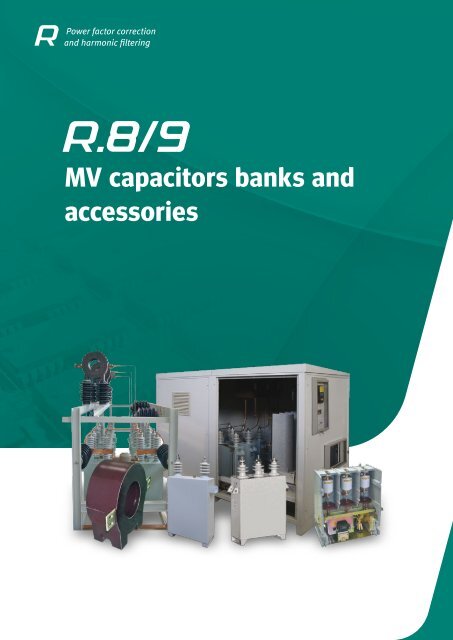
MV capacitors banks and accessories - Circutor
MV capacitors banks and accessories - Circutor
MV capacitors banks and accessories - Circutor
- No tags were found...

You also want an ePaper? Increase the reach of your titles
YUMPU automatically turns print PDFs into web optimized ePapers that Google loves.
Power factor correction<strong>and</strong> harmonic filtering<strong>MV</strong> <strong>capacitors</strong> <strong>banks</strong> <strong>and</strong><strong>accessories</strong>
<strong>MV</strong> <strong>capacitors</strong> <strong>banks</strong> <strong>and</strong> <strong>accessories</strong>Introduction· ························································································ R8/9- 3R.8 - <strong>MV</strong> <strong>capacitors</strong> <strong>and</strong> <strong>accessories</strong>CHV-MSingle-phase capacitor (indoor <strong>and</strong> outdoor use) ································································ R8-13CHV-TThree-phase capacitor (Indoor use, with fuses <strong>and</strong> discharge resistor, internal)· ······································· R8-17LVCThree-phase contactor for <strong>MV</strong> <strong>capacitors</strong>. · ···································································· R8-19R<strong>MV</strong>Choke reactor for capacitor <strong>banks</strong>· ··········································································· R8-20R.9 - <strong>MV</strong> Capacitor <strong>banks</strong>CIRKAP-CFixed or automatic capacitor <strong>banks</strong> in cabinet· ·································································· R9-22CIRKAP-GPHigh-powered capacitor <strong>banks</strong> in cabinet ······································································ R9-25CIRKAP-CMFR / CMARFixed or automatic capacitor <strong>banks</strong> in cabinet with detuned filters· ·················································· R9-25CIRKAP-BCapacitor <strong>banks</strong> in frames· ················································································· R9-26R8/9-2
Power factor correction<strong>and</strong> harmonic filteringMedium Voltage Power Factor correction<strong>MV</strong> Power factor correction is directlyrelated to the different aspects that assistthe technical management of transport<strong>and</strong> distribution networks. Theseare:}}Power quality. This involves the increasein the levels of voltage in substationbusbars <strong>and</strong> line ends.}}Optimisation of the installation'scost of operation. In other words, thedecrease of the reactive energy <strong>and</strong>,therefore, the reduction of apparentpower entail two aspects of a strongtechnical relevance:• yReduction of losses• yIncrease in the performance of transformers<strong>and</strong> installations}}Reduction of the economic cost ofenergy.An in-depth description of each point isprovided in the following sections.Supply quality, voltage levelThere are two cases: control of voltagein <strong>MV</strong> substation busbars <strong>and</strong> lineends.►Control ► of voltage in substation busbarsOne of the critical points in the distributionof electrical energy is maintainingvoltage in line ends. Distribution companiesusually maintain the <strong>MV</strong> levelsabove its nominal value.Therefore, <strong>MV</strong> capacitor <strong>banks</strong> areused. In fact, the connection of capacitor<strong>banks</strong> has an associated increase involtage in the connection points.The IEC 60871-1 St<strong>and</strong>ard facilitatesthe expression to calculate the increasein voltage produced after the connectionof <strong>capacitors</strong> (See table below), dependingon the characteristics of the networkwhere the capacitor bank is connected.The power, type of unit <strong>and</strong> level ofdivision depend on the criteria used bydistribution Companies.However, the division of total power indifferent steps can be used to improvethe levels of voltage under differentsubstation load conditions, avoiding anexcess capacitive power in the network.►Control ► of voltage in line endsIn the case of very long <strong>MV</strong> lines, thevoltage in branch points might be decreasedby the effects of the conductorcable. This is quite important in areaswith a rural overhead distribution or witha high level of dispersion of consumers.The connection of capacitor <strong>banks</strong> atthe end of a line allows a decrease ofvoltage drops at the line end, as wellas the reduction in the level of cablelosses.Optimisation of the installation's costof operationThe generation, transmission <strong>and</strong> distributionof energy entails an importantamount of energy lossesIn general, these losses are divided inthe following:}}Generation losses <strong>and</strong> substations}}Losses in the transmision system}}Losses in <strong>MV</strong>/HV substations}}Losses in the distribution linesR. 8 /9Comprehensive information about thelosses in the <strong>MV</strong> distribution lines isshown next.Reduction of losses in <strong>MV</strong> lines.Capacitor <strong>banks</strong> can be installed to decreasethe level of losses in a <strong>MV</strong> distributionline.In fact, the installation of the capacitorwill produce a direct reduction of the reactiveenergy (Q network) <strong>and</strong> apparentenergy requested from the system.R8/9-3
<strong>MV</strong> <strong>capacitors</strong> <strong>banks</strong> <strong>and</strong> <strong>accessories</strong>Therefore, in accordance with the directrelationship between current power values,the value of Joule effect losses willdecrease.The following table shows the expressionsrequired for the calculation ofJoule effect losses, the reactive energyconsumption of the cable <strong>and</strong> decreasein the losses when a capacitor bank isconnected.Increase of the voltage when a capacitorbank is connected IEC 60871-1Units used to underst<strong>and</strong> the calculation expressions:P active power transmitted by the line in kWQQ bankIUR 1X 1LS CCreactive energy absorbed without capacitor <strong>banks</strong>power of the capacitor bank in <strong>MV</strong>·AcurrentNetwork voltage in kVresistance of the cable in Ω/kmreactor of the cable in Ω/kmlength of the line in kmshort-circuit power in the connection point in <strong>MV</strong>·A.This point is important when makingthe economic assessment of theperformance of an installation, sincethere is an added “hidden cost” tothe payment for reactive energyconsumption, which is representedby the active energy dissipated duringdistribution.Example of a reduction of Joule effectlosses in an overhead distributionline system.In this case, the evolution of the linelosses <strong>and</strong> voltage drops is analysed ina distribution system rated at 20 kV withno capacitor <strong>banks</strong> connected.The effect of capacitor <strong>banks</strong> in a <strong>MV</strong>overhead distribution line in a rural areais compared between <strong>banks</strong>, wherethere are two distribution centres, A <strong>and</strong>B.Line voltage dropsLine <strong>and</strong> cable dischargeJoule effect losses in a lineThe decrease in apparent power afterthe connection of a capacitor bank entailstwo immediate consequences:}}Decrease of the load transmittedthrough cablesState of loads with no capacitor<strong>banks</strong> connectedReactive energy consumption in a line}}Increase of the supply capacity oftransformersThe system's power situation is shownon the following table:Reduced losses after the connection ofa capacitor bank}}Increase of the voltage at the end ofthe lineThe connection conditions in the connectionpoint with electrical system Care not very good, i.e., the apparentpower volume is high <strong>and</strong> the powerfactor is low.C ConnectionpointA DistributionCentreB DistributionCentreActive power (MW) 7,39 2,7 4,39Reactive energy (Mvar) 3,70 1,23 2,13Apparent power (<strong>MV</strong>·A) 8,26 2,97 4,88cos φ 0,89 0,91 0,9Joule effect losses (kW) - 114,5 185reactive consumed by the line (kvar) - 129 208Voltage drops (%) - 5,2 5,25R8/9-4
<strong>MV</strong> <strong>capacitors</strong> <strong>banks</strong> <strong>and</strong> <strong>accessories</strong>Situation with connected capacitor<strong>banks</strong>A 1,100 kvar capacitor bank at 20 kV isconnected to distribution centre A (BCA)<strong>and</strong> a 2,000 kvar capacitor bank at 20kV is connected to distribution centreB (BCB) to improve the network conditions.The balance of power is modified, asshown on the following table:In this case, the conditions in C havebeen substantially optimised. In addition,losses have decreased throughoutthe lines <strong>and</strong> the levels of voltage haveincreased in the distribution centres.C ConnectionpointA Distribution Centrewith BCAB DistributionCentrewith BCBActive power (MW) 7,33 2,7 4,39Reactive energy (Mvar) 0,54 0,13 0,13Apparent power (<strong>MV</strong>·A) 7,36 2,7 4,39cos φ 0,99 0,99 0,99Joule effect losses (kW) - 94 150Reactive consumed by the line (kvar) - 106 170Voltage drops (%) - 3,9 3,8Active power savings (kW) - 20 35Therefore, the operation <strong>and</strong> performanceof the line has been optimised <strong>and</strong>the level of voltage is guaranteed for users.ConclusionsCapacitor <strong>banks</strong> are vital for the adequatetechnical <strong>and</strong> economic managementof the electrical system, optimisingits operation.<strong>MV</strong> Electrical energy distribution systemsTechnical optimisationCapacitor <strong>banks</strong>CIRKAP}}Helping control voltage throughoutthe transmission <strong>and</strong> distribution system}}Discharging lines <strong>and</strong> transformers}}Reduction of the level of lossesthroughout the systemPower qualityOptimisation of networkoperation costEconomicoptimisationEconomic optimisationReduction of the cost of energy with thedecrease of the reactine energy consumedReduction of the hidden cost of losses intransmission <strong>and</strong> distribution linesMore efficient optimisation of installationsIncrease of voltages in:- Busbars- Line ends- Decrease of losses- Discharge of lines<strong>and</strong> cables- Discharge of transformersManagement of electrical loads in distribution systemsLower cost of energy:- Lower consumption of kW- Lower consumption of kvarR8/9-5
<strong>MV</strong> <strong>capacitors</strong> <strong>banks</strong> <strong>and</strong> <strong>accessories</strong>Where to compensate in <strong>MV</strong>Electrical energy generation, transmission<strong>and</strong> distributionReactive energy transmission <strong>and</strong> distributionthroughout the electrical system isnoteworthy, as stated above. Therefore,the reactive energy must be compensatedin determined points of the electricalnetwork. These are:}}Generation stations: Such as lowpoweredhydroelectric power plants <strong>and</strong>wind farms}}Receiving / distribution substations.(for example, reception 400 kV, distributionat 20 kV)}}Distribution centresIndustrial installations with <strong>MV</strong> distribution<strong>and</strong> consumptionIn general, the installations that distribute<strong>and</strong> consume <strong>MV</strong> are likely to becompensated.For example:}}Pumping stations}}Mining}}Industry: cement, chemical, steel,etc.There are transformers, asynchronousmotors or electric arc equipment in all ofthese industries, which are large reactiveenergy consumers.<strong>MV</strong> distribution <strong>and</strong> LV consuminginstallationsIn <strong>MV</strong> receiving installations with a distribution<strong>and</strong> consumption of LV, the compensationmust always be carried out inLow Voltage. The reasons are:}}Low power is cheaper in LV}}More accurate regulationComponents for <strong>MV</strong> capacitor <strong>banks</strong>CHV CapacitorsConfiguration of <strong>capacitors</strong>►Single-phase►Capacitor with two terminals. Capacitorbank installation in a star or double stararrangement. Common in networks witha power rating that exceeds 11 kV or incapacitor <strong>banks</strong> with lower voltages <strong>and</strong>higher power levels.►Three-phase►Capacitor with three terminals. Installationin low <strong>and</strong> medium-powered capacitor<strong>banks</strong> in networks with a power ratingof up to 11 kV.Capacitor compositionThe CHV Medium Voltage <strong>capacitors</strong>are composed of different basiccapacitive elements. These basic unitsare connected in groups in series <strong>and</strong>in parallel with the purpose of achievingthe power <strong>and</strong> voltage levels required.After assembling the set of elements,the set is introduced in a stainless steelbox, adding the porcelain terminals <strong>and</strong>impregnating the elements in oil (biodegradable),guaranteeing the unit's perfectinsulation <strong>and</strong> operation.Insulation levels (BIL)Maximum voltage supported by the materialin two cases, in accordance withthe IEC St<strong>and</strong>ard:}}At the industrial frequency during1 minute. Verification of the insulationof the unit, simulating a high networkvoltage ( kV ef.)}}Impulse, ray-type (shockwave) 1.2 /50 µs. Verification of the insulation of theunit, simulating a ray discharge ( kV peak)In the case of three-phase <strong>capacitors</strong>,the degree of insulation corresponds tothat immediately above its nominal voltage.Example: Three-phase capacitor CHV-T 300 kvar, 6.6 kV. Level of insulation7.2 kVIn single-phase <strong>capacitors</strong>, the selectioncriteria is different to that of threephase<strong>capacitors</strong>. The levels of insulationcorrespond to the same levels ofthe network when it is connected to thecapacitor bank in equipment that is notinsulated from earth (IEC 60.671-1).Example: Capacitor bank, 3 Mvar at20 kV. Composed of 6 units, 500 kvar,11.56 kV. Level of insulation of <strong>capacitors</strong>24 kV, (50/125 kV)Leakage linesCapacitor insulator flash-over perimeter.Directly related to the levels of pollution.However, when there is a high numberof LV / <strong>MV</strong> transformers, we recommendthe installation of LV regulated capacitor<strong>banks</strong> <strong>and</strong> a fixed <strong>MV</strong> section.Insulation level (kV)Voltage at industrialfrequency (kV ef.)Shockwave(kV peak)7,2 20 60 19012 28 75 19017,5 38 95 30024 50 125 43536 70 170 600Table 1Leakage lines (mm)R8/9-6
<strong>MV</strong> <strong>capacitors</strong> <strong>banks</strong> <strong>and</strong> <strong>accessories</strong>Pollution levelsThe pollution level defines the environmentalcontamination existing in theplace where equipment is installed.Therefore, to avoid insulation defects asa consequence of flash-over, the greaterthe degree of environmental pollution,the greater the leakage of insulators.It is expressed in mm / kV. In otherwords, the relationship between the insulatorleakage line <strong>and</strong> network voltage.The pollution levels defined areshown on the following table:ClassificationLowMediumHighVery highPollution level16 mm/kV20 mm/kV25 mm/kV31 mm/kVProtection of <strong>capacitors</strong> with internalfusesThe capacitor, as any element in anelectrical installation, must be capableof eliminating the defects that can becaused inside. To do so, all basic capacitiveelements of the capacitor areprotected with an internal fuse.Operational advantages}}Immediate disconnection of the damagedelement}}Minimum generation of gases insidethe capacitor, therefore, a very low internaloverpressure effect}}Continuity of the service. The removalof the damaged unit means thatthe unit can remain connected. Optionalplanning of the capacitor bank's maintenance}}Simpler maintenanceDesign advantages}}Increase capacitor power}}Use of less <strong>capacitors</strong> in each capacitorbank}}Reduction of the size of frames orcabinet}}Cheaper capacitor <strong>banks</strong>In case of a defect in a basic capacitiveelement, the healthy elements willbe discharged in parallel to the faultyelement. The discharge will immediatelymelt the internal fuse of the damagedunit. This system has a series of advantagesthat are classified in two groups:R8/9-7
<strong>MV</strong> <strong>capacitors</strong> <strong>banks</strong> <strong>and</strong> <strong>accessories</strong><strong>MV</strong> Capacitor <strong>banks</strong>Configuration of capacitor <strong>banks</strong>The use of different configurations iscommon in <strong>MV</strong> capacitor <strong>banks</strong>. Thesedepend on the type of capacitor used<strong>and</strong>, above all, on the installation's electricalparameters.Capacitor <strong>banks</strong>, three-phase <strong>capacitors</strong>These units are useful in industrial installations,since they are capable ofhosting low <strong>and</strong> medium-powered applicationsin small dimensions.The maximum service voltage is 11 kV<strong>and</strong> the maximum power is 1.4 Mvar.The most common applications are:}}Compensation of motors}}Compensation of transformers}}Automatic capacitor <strong>banks</strong>Capacitor <strong>banks</strong> with single-phase<strong>capacitors</strong> connected in a doublestararrangementThis is the most common configurationin medium <strong>and</strong> large-powered applications.The double-star is formed by two starsjoined by a common neutral.A current transformer is connected tothe neutral to detect the default currentsof <strong>capacitors</strong>.This arrangement of <strong>capacitors</strong> canbe used to operate the unit, whateverthe power <strong>and</strong> voltage levels required,based on the use of st<strong>and</strong>ard <strong>capacitors</strong>.In fact, the capacitor or group of <strong>capacitors</strong>in each branch will have an appliedvoltage corresponding to the phase voltage,as seen on the figure.After defining the voltage of each capacitor<strong>and</strong>, therefore, the number ofunits, so the power of each capacitor isdefined.Capacitor <strong>banks</strong> with single-phase<strong>capacitors</strong> connected in a star arrangementThe application of this configuration islimited to low-powered capacitor <strong>banks</strong>,which can not be resolved with threephase<strong>capacitors</strong> due to the workingvoltage.A practical case is, for example, a 450kvar capacitor bank at 15 kv.This case will be resolved with 3 <strong>capacitors</strong>,with a nominal voltage of 150 kvarat 8.67 kVl.The level of insulation of <strong>capacitors</strong> correspondsto that of the network, i.e.,17.5 kV.This configuration is used in the followingcases:}}Networks with service voltages exceeding11 kV}}Networks with voltages under 11 kV<strong>and</strong> power levels above 1.6 MvarR8/9-8
<strong>MV</strong> <strong>capacitors</strong> <strong>banks</strong> <strong>and</strong> <strong>accessories</strong>Compensation methodThe compensation method in <strong>MV</strong> installationsis carried out with a fixed or automaticsystem, as in LV installations. Itdepends on the type of installation, itsconfiguration, the load ratio, as well asthe purpose for which the unit was installed.Fixed compensationWhen the reactive energy levels arehigh <strong>and</strong> an important portion of theselevels is more or less constant, a fixedcompensation unit is installed. This iscommon in installations with a connectionto High Voltage networks <strong>and</strong> MediumVoltage distribution.Another application is in industrial installationswith a reduced number of receivers<strong>and</strong> where the operating ratios donot require the machines to interrupttheir operation simultaneously.Automatic compensationThe installation of a unit that can followthe fluctuations is required in installationswith large variations in load.An example is the distribution branchof an industry at 6.3 kV with <strong>MV</strong> loads<strong>and</strong> LV transformers, as shown on thefigure.Protection of capacitor <strong>banks</strong>In general, capacitor bank protectionsystems are divided in external <strong>and</strong> internalprotections.Internal protectionInternal protection systems protect unitsagainst defects inside <strong>capacitors</strong>. Thistype of protection is guaranteed by internalfuses. In capacitor <strong>banks</strong> configuredin a double star arrangement, thisis combined with an unbalanced protection.This system is composed of acurrent transformer <strong>and</strong> an associatedrelay.In case of an internal fault in one of the<strong>capacitors</strong>, an unbalanced current willflow through the capacitor.This current is detected by the currenttransformer. The associated relay willsend an order to disconnect the switching<strong>and</strong>/or protection unit.External protectionThe protection systems used in capacitor<strong>banks</strong> depend on the configuration ofthe bank <strong>and</strong> its application.General component design criteriaIn accordance with the IEC 60871-1St<strong>and</strong>ard, <strong>capacitors</strong> are designed tosupport a 30% overload of permanentcurrent.Therefore, the St<strong>and</strong>ard recommendsthat the components in the capacitorbank support a maximum of 1.43 timesthe nominal current. This criterion isapplicable to the following:}}Power cables}}General devices}}Choke REACTORSCAPACITOR BANKS WITH THREE-PHASE CAPACITORSNominal voltages ≤ 11 kVCapacitor bank power ≤ 1.4 MvarFixed for motor: High rupture powerfuses (HRP) with meltdown indication.Automatic: HRP fuses combinedwith a contactorCAPACITOR BANKS WITH A DOUBLE-START ARRANGEMENTNominal voltages > 11 kVCapacitor bank power > 1.4 MvarAutomatic switch, with the followingprotection elements:••Overload <strong>and</strong> short-circuit••Homopolar••UnbalanceNotes:••Overload protection is recommended in busbars.••The protection system can beinstalled on the same capacitor bankor in the centre of <strong>MV</strong> cabinetR8/9-9
<strong>MV</strong> <strong>capacitors</strong> <strong>banks</strong> <strong>and</strong> <strong>accessories</strong>How to select a Medium Voltage capacitor bankThe CIRKAP capacitor bank seriesoffers a full range of Medium Voltagecapacitor <strong>banks</strong> in fixed <strong>and</strong> automaticversions (only in the case of capacitor<strong>banks</strong> in the cabin).The CIRKAP capacitor <strong>banks</strong> aredivided in two main groups:}}CIRKAP-C}}CIRKAP-BCIRKAP capacitor <strong>banks</strong>CABINCIRKAP-CFRAMESCIRKAP-BFixed capacitor<strong>banks</strong>Automaticcapacitor <strong>banks</strong>Medium voltagecapacitor <strong>banks</strong>High-voltagecapacitor <strong>banks</strong>St<strong>and</strong>ardCMFHighpowerCMF-GPWith filtersCMFRSt<strong>and</strong>ardCMAHighpowerCMA-GPWith filtersCMARSt<strong>and</strong>ardBMFWith filtersBMFRSt<strong>and</strong>ardBAFConstruction designDesignCabinFrameElectrical parametersFrequencyHzForm of correction FixedRegulation (when it is automatic)AutomatickvarNominal voltagePowerkVkvarLocationIndoorOutdoorInsulation level (BIL)kVTypeSt<strong>and</strong>ardWith filtersInformation required for installationSwitchgear <strong>and</strong> protectionsMore capacitor <strong>banks</strong> installedYesNoContactorYesNoPower in these capacitor <strong>banks</strong>kvarAutomatic switchYesNoExistence of harmonicsYesNoCutt off powerPhase protectiontransformersOverload <strong>and</strong>short-circuit relayEarth switch withinterlockingYesYesYeskANoNoNoMeasurement in the caseof harmonicsShort-circuit powerAltitude (over sea level)kvar<strong>MV</strong>·AmPollution level St<strong>and</strong>ard SpecialR8/9-10
INSTALLATIONCAPACITOR BANKCONFIGURATIONDESIGNCAPACITORSREACTORSSWITCHGEAR<strong>MV</strong> <strong>capacitors</strong> <strong>banks</strong> <strong>and</strong> <strong>accessories</strong>Equipment <strong>and</strong> component definitionguideGENERAL BASIC INFORMATIONCalculation exampleThe following example shows the calculation of the basicparameters of a capacitor bank in two scenarios:1••Network voltage (kV)••Network frequency (Hz)••Short-circuit power <strong>MV</strong>·A••Existence of more capacitor <strong>banks</strong>(Yes/No)••Existence of harmonics (Yes/No)Selection of the complete capacitor bank. Selection of thecomponents for the assembly of a capacitor bankTo do so,follow the steps defined in the “Equipment <strong>and</strong> componentdefinition guide”Capacitor bank selection2••Power of the capacitor bank (kvar)••Capacitor bank voltage (kV)••Fixed / automatic••Type: st<strong>and</strong>ard or with filters••General protection requirement(Yes/No)••Location: indoor or outdoor••Other special needs5.1. Installation dataThis installation requires the installation oftwo capacitor <strong>banks</strong>, 4 Mvar at 20 kV, on the same substationbusbar.DEFINITION OF THE CAPACITOR BANKWhen U > 11.5 kV <strong>and</strong> Q < 1 400 kvar••Capacitor bank, three-phase <strong>capacitors</strong>3When U > 11.5 <strong>and</strong> Q < 1 400 kvar orWhen U < 11.5 <strong>and</strong> Q > 1 400 kvar••Double-star capacitor bank,single-phase <strong>capacitors</strong>4Fixed:••CMF••BMFAutomatic:••CMA••Number <strong>and</strong> power of stepsDEFINITION OF COMPONENTS56••Configuration, single or three-phase••Nominal voltage (kV)••Frequency (Hz)••Insulation level (kV)••Reactive power (kvar)••Special leakage line (mm/kV)••Quantity (3 per capacitor bank or step)••Inductance (µH)••Current (A)••Level of insulation (kV)••Short-duration current (kA/1s)••Location: indoor or outdoor7For automatic capacitor <strong>banks</strong>••Contactor U < 12 kV••Switch U > 12 kV••Capacitive power to cut off(kvar)••Insulation level (kV)••Switch cut off power (kA)R8/9-11
CAPACITORSINSTALLATIONCAPACITOR BANKSWITCHGEARREACTORSCONFIGURATIONDESIGN<strong>MV</strong> <strong>capacitors</strong> <strong>banks</strong> <strong>and</strong> <strong>accessories</strong>GENERAL BASIC INFORMATIONDEFINITION OF THE CAPACITOR BANK1••Network voltage (kV): 20 kV••Network frequency (Hz): 50 Hz••Short-circuit power <strong>MV</strong>·A: 150 <strong>MV</strong>·A••Existence of more capacitor <strong>banks</strong> (Yes/No): NO••Existence of harmonics (Yes/No): NO3U > 11.5 kV <strong>and</strong> Q > 1 400 kvarDouble-star capacitor bank, single-phase<strong>capacitors</strong>.2••Power of the capacitor bank (kvar): 4 Mvar••Capacitor bank voltage (kV): 20 kV••Fixed / automatic: Fixed. Control stationoperations••Type: st<strong>and</strong>ard or with filters: St<strong>and</strong>ard••Need for General Protection (Yes/No): No.Forecasted protection cabinet••Location: indoor or outdoor: Indoor••Other special needs: No4••Fixed, assembled in CMF24D type cabin:Cabin CMF24D /4000/20Selection of componentsDEFINITION OF COMPONENTSThere are two possible scenarios:−−Firstly, the connection of a capacitor bank whilethe other one is disconnectedSecondly, the behaviour of the second capacitor5••Single or three-phase configuration: Single-phase(CHV-M)••Nominal voltage: corresponds to the phase voltage11.56 kV••Frequency: 50 Hz••Insulation level: corresponds to the BIL network: 24kV, 50 / 125 kV••Power (kvar): The number of <strong>capacitors</strong> in the unitis calculatedThere are two options, 6 or 9 <strong>capacitors</strong>. The powerratings would be:6bank while the first one is connectedInsulated capacitor bank. Check the peakconnection currentTherefore, since the value is under the maximumsupported by the St<strong>and</strong>ard, the R<strong>MV</strong> chokeREACTORS will not be required.Capacitor <strong>banks</strong> in parallel. This is the mostunfavourable case. With the formulae given in thechoke reactor section (page 16), we can obtain thefollowing results:For 6 <strong>capacitors</strong>: 667 kvarFor 9 <strong>capacitors</strong>: 445 kvarThe second option is selected, with a capacitorpower of 450 kvar. Therefore, a double asymmetricalstar configuration with 9 <strong>capacitors</strong> will be used.••Special leakage line: Clean atmosphere, class1, 16 mm / kV.••Quantity (3 per capacitor bank or step): 3••Inductance: 30 µH••Current: 115.6 * 1,5 (max. overload coefficient) =173.4 A . St<strong>and</strong>ardized value 175 A••Insulation level: corresponds to the BIL network: 24kV, 50/125 kV (need for additional insulation elements)••Short-duration current (kA/1s): 43 I n••Location: indoor or outdoor: Indoor7In this example, the capacitor <strong>banks</strong> do not include the switchgear, but there is information provided for thedesigner, for the correct definition of the general protection cabin:••Automatic switch: 400 or 630 A. Recommended interruption method: vacuum or SF6••Capacitive power interrupted (kvar): 4 000 kvar••Insulation level (kV): 24 kV••Interrupting power of the switch (kA): 12.5 kAR8/9-12
<strong>MV</strong> <strong>capacitors</strong> <strong>and</strong> <strong>accessories</strong>CHV-MSingle-phase capacitor (indoor <strong>and</strong> outdoor use)DescriptionFeaturesThe CHV Medium Voltage <strong>capacitors</strong> arecomposed of different capacitive elements.These basic units are connected in series<strong>and</strong> parallel with the purpose of obtaining thepower at the necessary voltage.All elements are protected with an internalfuse that will be disconnected in case of afault, isolating the basic unit damaged.The protection with internal fuses will increasethe security of the system <strong>and</strong> continuityof the service.ApplicationCHV-M <strong>capacitors</strong> are used to build fixed <strong>and</strong>automatic <strong>MV</strong> capacitor <strong>banks</strong>.We will vary the number of <strong>capacitors</strong> in parallel<strong>and</strong>/or in series, depending on the power<strong>and</strong> voltage levels required.Its stainless steel box means that the CHVcapacitor is versatile <strong>and</strong> can be used in indoor<strong>and</strong> outdoor applications.Voltage1 ... 20 kVNominal power25 ... 600 kvarFrequency50 or 60 HzDielectric losses≤ 0.2 W / kvarCapacity tolerance -5 ... +10 %LocationIndoor / OutdoorProtectionInternal fuse (depending on the type)Discharge resistance (in compliance with IEC 60871-1)LocationIndoorDischarge time≤ 10 minutesResidual voltage≤ 75 VInsulatorsMaterialPorcelainPollution level16 mm / kV (other leakage lines, on dem<strong>and</strong>)Insulation level 12 - 17.5 - 24 - 36 kV (see table 1)OverloadIn current1.3 I npermanentIn voltage1.1 U n12 h in 24 hours1.15 U n30 min in 24 hours1.2 U n5 min in 24 hours1.30 U n1 min in 24 hoursAmbient conditionsOperating temperature Category C (in accordance with IEC 60871-1)Maximum temperature (*2)50º CMaximum mean value during 24 hours40º CMaximum mean value during 1 year 30 ºCBuild featuresDielectricRough polypropylene filmElectrodeAluminium sheetImpregnating oilSAS-40E or M/DBT (PCB-free)Dimensions (mm)depending on the typeWeightdepending on the type (see table)Painted stainless steel, RAL 7035Box2 wings to fix to the frame <strong>and</strong> avoidmechanical efforts on porcelain terminalsAssembly positionSt<strong>and</strong>ardsIEC 60871-1, IEC 60871-4(*2) Understood as punctualHorizontal or verticalR8-13
<strong>MV</strong> <strong>capacitors</strong> <strong>and</strong> <strong>accessories</strong>CHV-MSingle-phase capacitor (indoor <strong>and</strong> outdooruse)DimensionsReferencesBIL: 28 / 75 kV - 6.6 kV (Network 11 kV). 50 Hzkvar Weight (kg) Dimensions (mm)width x height x depthTypeCode50 17 350 x 405 x 160 CHV-M 50 / 6.6(*) R8019375 20 350 x 455 x 160 CHV-M 75 / 6.6(*) R80195100 22 350 x 505 x 160 CHV-M 100 / 6.6 R80196133 25 350 x 565 x 160 CHV-M 133 / 6.6 R80197150 28 350 x 615 x 160 CHV-M 150 / 6.6 R80198167 30 350 x 615 x 160 CHV-M 167 / 6.6 R80199200 34 350 x 675 x 160 CHV-M 200 / 6.6 R8019A250 40 350 x 785 x 160 CHV-M 250 / 6.6 R8019B300 46 350 x 775 x 175 CHV-M 300 / 6.6 R8019C400 57 350 x 915 x 175 CHV-M 400 / 6.6 R8019F500 68 350 x 1055 x 175 CHV-M 500 / 6.6 R8019G600 79 350 x 1165 x 220 CHV-M 600 / 6.6 R8019HBIL: 38 / 95 kV - 8 kV (Network 13.2 kV). 50 Hzkvar Weight (kg) Dimensions (mm)width x height x depthTypeCode50 19 350 x 470 x 160 CHV-M 50 / 8(*) R801B375 23 350 x 520 x 160 CHV-M 75 / 8(*) R801B5100 25 350 x 570 x 160 CHV-M 100 / 8(*) R801B6133 28 350 x 620 x 160 CHV-M 133 / 8 R801B7150 31 350 x 680 x 160 CHV-M 150 / 8 R801B8167 33 350 x 680 x 160 CHV-M 167 / 8 R801B9200 38 350 x 740 x 160 CHV-M 200 / 8 R801BA250 43 350 x 850 x 160 CHV-M 250 / 8 R801BB300 49 350 x 940 x 160 CHV-M 300 / 8 R801BC400 61 350 x 1010 x 175 CHV-M 400 / 8 R801BF500 70 350 x 1190 x 175 CHV-M 500 / 8 R801BG600 81 350 x 1230 x 175 CHV-M 600 / 8 R801BHR8-14
<strong>MV</strong> <strong>capacitors</strong> <strong>and</strong> <strong>accessories</strong>CHV-MSingle-phase capacitor (indoor <strong>and</strong> outdoor use)ReferencesBIL: 38 / 95 kV - 9.1 kV (Network 15 kV). 50 Hzkvar Weight (kg) Dimensions (mm)width x height x depthTypeCode50 19 350 x 470 x 160 CHV-M 50 / 9.1(*) R801D375 23 350 x 520 x 160 CHV-M 75 / 9.1(*) R801D5100 25 350 x 570 x 160 CHV-M 100 / 9.1(*) R801D6133 28 350 x 620 x 160 CHV-M 133 / 9.1 R801D7150 31 350 x 620 x 160 CHV-M 150 / 9.1 R801D8167 33 350 x 680 x 160 CHV-M 167 / 9.1 R801D9200 38 350 x 740 x 160 CHV-M 200 / 9.1 R801DA250 43 350 x 850 x 160 CHV-M 250 / 9.1 R801DB300 49 350 x 860 x 160 CHV-M 300 / 9.1 R801DC400 61 350 x 1010 x 175 CHV-M 400 / 9.1 R801DF500 70 350 x 1160 x 175 CHV-M 500 / 9.1 R801DG600 81 350 x 1230 x 200 CHV-M 600 / 9.1 R801DH(*) No internal fusesBIL: 50 / 125 kV - 12.1 kV (Network 20 kV). 50 Hzkvar Weight (kg) Dimensions (mm)width x height x depthTypeCode50 19 350 x 510 x 160 CHV-M 50 / 12.1(*) R801F375 23 350 x 560 x 160 CHV-M 75 / 12.1(*) R801F5100 25 350 x 620 x 160 CHV-M 100 / 12.1(*) R801F6133 28 350 x 660 x 160 CHV-M 133 / 12.1(*) R801F7150 31 350 x 720 x 160 CHV-M 150 / 12.1(*) R801F8167 33 350 x 780 x 160 CHV-M 167 / 12.1 R801F9200 38 350 x 890 x 160 CHV-M 200 / 12.1 R801FA250 43 350 x 890 x 160 CHV-M 250 / 12.1 R801FB300 49 350 x 900 x 175 CHV-M 300 / 12.1 R801FC400 61 350 x 1090 x 175 CHV-M 400 / 12.1 R801FF500 70 350 x 1230 x 175 CHV-M 500 / 12.1 R801FG600 81 350 x 1270 x 200 CHV-M 600 / 12.1 R801FHR8-15
<strong>MV</strong> <strong>capacitors</strong> <strong>and</strong> <strong>accessories</strong>CHV-MSingle-phase capacitor (indoor <strong>and</strong> outdoor use)ReferencesBIL: 70 / 170 kV - 15.2 kV (Network 25 kV). 50 Hzkvar Weight (kg) Dimensions (mm)width x height x depthTypeCode50 19 350 x 510 x 145 CHV-M 50 / 15.2(*) R801H375 23 350 x 590 x 145 CHV-M 75 / 15.2(*) R801H5100 25 350 x 590 x 145 CHV-M 100 / 15.2(*) R801H6133 28 350 x 670 x 145 CHV-M 133 / 15.2(*) R801H7150 31 350 x 670 x 145 CHV-M 150 / 15.2(*) R801H8167 33 350 x 760 x 145 CHV-M 167 / 15.2(*) R801H9200 38 350 x 760 x 145 CHV-M 200 / 15.2(*) R801HA250 43 350 x 860 x 145 CHV-M 250 / 15.2 R801HB300 49 350 x 940 x 145 CHV-M 300 / 15.2 R801HC400 61 350 x 980 x 175 CHV-M 400 / 15.2 R801HF500 70 350 x 1120 x 175 CHV-M 500 / 15.2 R801HG600 81 350 x 1260 x 175 CHV-M 600 / 15.2 R801HHBIL: 70/170 kV - 18.2 V (Network 30 kV). 50 Hzkvar Weight (kg) Dimensions (mm)width x height x depthTypeCode50 19 350 x 510 x 145 CHV-M 50 / 18.2(*) R801J375 23 350 x 590 x 145 CHV-M 75 / 18.2(*) R801J5100 25 350 x 590 x 145 CHV-M 100 / 18.2(*) R801J6133 28 350 x 670 x 145 CHV-M 133 / 18.2(*) R801J7150 31 350 x 670 x 145 CHV-M 150 / 18.2(*) R801J8167 33 350 x 760 x 145 CHV-M 167 / 18.2(*) R801J9200 38 350 x 760 x 145 CHV-M 200 / 18.2(*) R801JA250 43 350 x 860 x 145 CHV-M 250 / 18.2(*) R801JB300 49 350 x 940 x 145 CHV-M 300 / 18.2 R801JC400 61 350 x 980 x 175 CHV-M 400 / 18.2 R801JF500 70 350 x 1120 x 175 CHV-M 500 / 18.2 R801JG600 81 350 x 1260 x 175 CHV-M 600 / 18.2 R801JH(*) No internal fusesR8-16
<strong>MV</strong> <strong>capacitors</strong> <strong>and</strong> <strong>accessories</strong>CHV-TThree-phase capacitor (Indoor use, with fuses<strong>and</strong> discharge resistor, internal)DescriptionFeaturesThe CHV Medium Voltage <strong>capacitors</strong> arecomposed of different capacitive elements.These basic units are connected in series<strong>and</strong> parallel with the purpose of obtaining thepower at the necessary voltage.All elements are protected with an internalfuse that will be disconnected in case of afault, isolating the basic unit damaged.The protection with internal fuses will increasethe security of the system <strong>and</strong> continuityof the service.ApplicationCHV-T <strong>capacitors</strong> are used to build fixed <strong>and</strong>automatic capacitor <strong>banks</strong> of up to 12 kV.The stainless steel box of the CHV-T makes ita versatile product that can be used in indoor<strong>and</strong> outdoor applications.Voltage 1 ... 12 kVNominal power25 ... 500 kvarFrequency50 or 60 HzDielectric losses≤ 0.2 W / kvarCapacity tolerance -5 ... +10 %LocationIndoor / OutdoorProtectionInternal fuse (depending on the type)Discharge resistance (in compliance with IEC 60871-1)LocationIndoorDischarge time≤ 10 minutesResidual voltage≤ 75 VInsulatorsMaterialPorcelainPollution level16 mm / kV (other leakage lines, on dem<strong>and</strong>)Insulation level 12 - 17.5 - 24 - 36 kV (see table 1)OverloadIn current1.3 I npermanentIn voltage1.1 U n12 h in 24 hours1.15 U n30 min in 24 hours1.2 U n5 min in 24 hours1.30 U n1 min in 24 hoursAmbient conditionsOperating temperature Category C (in accordance with IEC 60871-1)Maximum temperature (*2) 50 ºCMaximum mean value during 24 hours 40 ºCMaximum mean value during 1 year 30 ºCBuild featuresDielectricRough polypropylene filmElectrodeAluminium sheetImpregnating oilSAS-40E or M/DBT (PCB-free)Dimensions (mm)depending on the typeWeightdepending on the type (see table)Painted stainless steel, RAL 7035Box2 wings to fix to the frame <strong>and</strong> avoidmechanical efforts on porcelain terminalsAssembly positionSt<strong>and</strong>ardsIEC 60871-1, IEC 60871-4(*2) Understood as punctualHorizontal or verticalR8-17
<strong>MV</strong> <strong>capacitors</strong> <strong>and</strong> <strong>accessories</strong>CHV-TThree-phase capacitor (Indoor use, with fuses<strong>and</strong> discharge resistor, internal)DimensionsM12100BH40321 2x÷9x16115P350430ReferencesBIL: 20 / 60 kV - 3.3 kV . 50 Hzkvar Weight (kg) Dimensions (mm) TypeCodewidth x height x depth50 17 350 x 405 x 160 CHV-T 50 /3.3 R8022375 20 350 x 455 x 160 CHV-T 75 /3.3 R80225100 22 350 x 505 x 160 CHV-T 100 /3.3 R80226150 28 350 x 555 x 160 CHV-T 150 /3.3 R80228200 34 350 x 675 x 160 CHV-T 200 /3.3 R8022A250 40 350 x 785 x 160 CHV-T 250 /3.3 R8022B300 46 350 x 875 x 160 CHV-T 300 /3.3 R8022C400 57 350 x 915 x 175 CHV-T 400 /3.3 R8022F500 68 350 x 1055 x 175 CHV-T 500 /3.3 R8022GBIL: 20 / 60 kV - 6.6 kV . 50 Hzkvar Weight (kg) Dimensions (mm) TypeCodewidth x height x depth50 17 350 x 405 x 160 CHV-T 50 /6.6 R8028375 20 350 x 455 x 160 CHV-T 75 /6.6 R80285100 22 350 x 505 x 160 CHV-T 100 /6.6 R80286150 28 350 x 615 x 160 CHV-T 150 /6.6 R80288200 34 350 x 675 x 160 CHV-T 200 /6.6 R8028A250 40 350 x 785 x 160 CHV-T 250 /6.6 R8028B300 46 350 x 875 x 160 CHV-T 300 /6.6 R8028C350 53 350 x 945 x 160 CHV-T 350 /6.6 R8028D400 57 350 x 1015 x 175 CHV-T 400 /6.6 R8028F500 68 350 x 1165 x 175 CHV-T 500 /6.6 R8028GBIL: 28 / 75 kV - 11 kVkvar Weight (kg) Dimensions (mm) TypeCodewidth x height x depth50 17 350 x 405 x 160 CHV-T 50 /11 R802B375 20 350 x 455 x 160 CHV-T 75 /11 R802B5100 22 350 x 455 x 160 CHV-T 100 /11 R802B6150 28 350 x 555 x 160 CHV-T 150 /11 R802B8200 34 350 x 675 x 160 CHV-T 200 /11 R802BA250 40 350 x 785 x 160 CHV-T 250 /11 R802BB300 46 350 x 875 x 160 CHV-T 300 /11 R802BC350 53 350 x 945 x 160 CHV-T 350 /11 R802BD400 57 350 x 915 x 175 CHV-T 400 /11 R802BF500 68 350 x 1055 x 175 CHV-T 500 /11 R802BGR8-18
<strong>MV</strong> <strong>capacitors</strong> <strong>and</strong> <strong>accessories</strong>LVCThree-phase contactor for <strong>MV</strong> <strong>capacitors</strong>.DescriptionFeaturesThe LVC contactor is a vacuum contactorprepared to control inductive <strong>and</strong> capacitiveloads.ApplicationFeaturesAuxiliary voltageNominal voltageNominal currentInterrupting powerFrequency220 V ac / 110 V dc (on dem<strong>and</strong>)6.6 kV400 A4 kA50 ... 60 HzThe LVC contactor has been specially designedfor industrial applications that require alarge number of switching operations. In particular,the loads from motors <strong>and</strong> <strong>capacitors</strong>.Insulation level7.2 kVCategory AC 3No. of operations 300 000Maximum operation power2 000 kvar at 6.6 kVThe LVC vacuum contactor is ideal for theBuild featuresswitching operations of capacitor <strong>banks</strong> be-ConnectionFixedtween 3.3 <strong>and</strong> 6.6 kV.Dimensions350 x 392 x 179 mmIts general features are as follows:WeightSt<strong>and</strong>ard22 kg}}Interrupting methods, vacuumIEC60470}}Total control of the electric arc in capacitiveswitching operations}}Very long working life}}Heavy insulation of the set, composed ofthree independent vacuum poles, assembledon an insulating structure}}Samll size}}Light unit, greatly optimised weight}}Easy to maintainDimensions23,4247419,1484,8398,644020,5ReferencesMaximum operating voltage Maximum current Type Auxiliary voltage Code6.6 kV ac 3 x 400 A LVC-6Z44ED 220 V ac R809116.6 kV ac 3 x 400 A LVC-6Z44ED 110 V dc R809110010000R8-19
<strong>MV</strong> <strong>capacitors</strong> <strong>and</strong> <strong>accessories</strong>R<strong>MV</strong>Choke reactor for capacitor <strong>banks</strong>DescriptionFeaturesChoke REACTORS are required to limit thetransient currents produced during the connectionof <strong>capacitors</strong>.FeaturesShort-duration nominal currentDynamic current43 I n/ 1 s2.5 I tCIRCUTOR's R<strong>MV</strong> units are encapsulatedin epoxy resin, which guarantees the degreeof insulation required.Insulation level 12 kV (28/75)Ambient conditionsOperating temperatureCategory BMean temperature 40 ºCApplicationThe connection of capacitor <strong>banks</strong> has veryhigh associated transient currents <strong>and</strong> voltages.The IEC 60871-1 St<strong>and</strong>ard defines the maximumvalue that can be supported by a capacitorbank as the peak connection value.This value is 100 times its nominal current.When this value is exceeded, R<strong>MV</strong> chokeREACTORS must be installed. These REAC-TORS are in charge of limiting the transientcurrent to values that can be supported bythe <strong>capacitors</strong>. The inductance value is variable,depending on the installation's conditions<strong>and</strong>, basically, on the following parameters:Build featuresTypeFittingsDimensions (mm)WeightEncapsulated in resinAir coreM12 / M16, depending on the typedepending on the typeColour colour RAL 8016St<strong>and</strong>ardIEC60289depending on the type (see table on the top)}}Short-circuit power of the installation}}Existence of more capacitor <strong>banks</strong>}}Interrupting power of automatic switches.The peak current value of the residual connectionmust also be lower than the interruptingpower of the switch unit after the reactorhas been installedR8-20
<strong>MV</strong> <strong>capacitors</strong> <strong>and</strong> <strong>accessories</strong>R<strong>MV</strong>Choke reactor for capacitor <strong>banks</strong>DimensionsTypeAØmmBØmmCmmDmmEmmFmmInsertsR<strong>MV</strong>-260 260 130 370 160 290 150 M12R<strong>MV</strong>-330 330 150 470 190 355 210 M12/M16ReferencesR<strong>MV</strong>-260I (A) L (μH) Weight (kg) Type Code50 350 13 R<strong>MV</strong> - 260 - 50 - 350 R8062860 250 14 R<strong>MV</strong> - 260 - 60 - 250 R80637100 100 16 R<strong>MV</strong> - 260 - 100 - 100 R80664125 50 14 R<strong>MV</strong> - 260 - 125 - 50 R80672175 30 14 R<strong>MV</strong> - 260 - 175 - 30 R80691R<strong>MV</strong>-330I (A) L (μH) Weight (kg) Type Code60 450 20 R<strong>MV</strong> - 330 - 60 - 450 R8073975 350 21 R<strong>MV</strong> - 330 - 75 - 350 R8074890 250 26 R<strong>MV</strong> - 330 - 90 - 250 R80757125 100 22 R<strong>MV</strong> - 330 - 125 - 100 R80774200 50 22 R<strong>MV</strong> - 330 - 200 - 50 R807A2250 30 23 R<strong>MV</strong> - 330 - 250 - 30 R807B1The R<strong>MV</strong> reactor selection parameters are:* Maximum working current (1.43 times I nof the unit)* Inductance required in μH* Insulation voltage kVThe insulation voltage is 12 kV (28/75). Other voltages, on dem<strong>and</strong>The thermal current is 43 I n/ 1 s. Other values, on dem<strong>and</strong>R8-21
<strong>MV</strong> Capacitor <strong>banks</strong>CIRKAP-CFixed or automatic capacitor <strong>banks</strong> in cabinetDescriptionThe installation of the capacitor <strong>banks</strong> of theCIRKAP-C series offers the following advantages:}}Protection against direct contacts of activeparts}}Space economy. The use of no securityenclosures <strong>and</strong> use of internal fuses allowsthe designers to greatly reduce the dimensionsof the unit}}Optional addition of switchgear to protectthe capacitor bank or perform automaticequipment functionsApplicationFeaturesThe most common applications are:Medium Voltage industrial networks}}Compensation of large motors. Usually 3to 11 kV}}Compensation of HV / <strong>MV</strong> transformers}}Fixed or automatic compensation of thefollowing installations: cement plants, pumpingstations, pipelines, mining, paper industry.}}Generation <strong>and</strong> distribution systems}}Receiving <strong>and</strong> distributing stations. Particularlyindoor installations, where the use ofspace is vital}}Generation stations that need an automaticpower factor regulation: small-scalehydraulic power plants, wind farms, etc.VoltageNominal powerFrequencyLocationDegree of protectionInsulation levelSetupCapacitorsCapacitor bankBuild featuresDimensions (mm)WeightPanels <strong>and</strong> frames1 ... 36 kV100 ... 14,000 kvar50 or 60 HzIndoor / OutdoorIP 23 (Other values, on dem<strong>and</strong>)7.2 ... 36 kVthree or single-phase, double stararrangement (depending on the type)Fixed or automaticdepending on the typedepending on the typePainted steel RAL 7035For outdoor use, treated <strong>and</strong> painted steelReferencesFixedShapeAutomatic(Maximum power per step)* Other power ratings, please askTypesPower (kvar)(*)St<strong>and</strong>ard 100 ...7200Insulation levels7.2 kV 12 kV 17.5 kV 24 kV 36 kVCMF7TCMF7DCMF12TCMF12DCMF17D CMF24D CMF36DHigh power 1800...14000 CMF12GP CMF17GP CMF24GP CMF36GPWith detuned filters 100...7200St<strong>and</strong>ard 100...8000CMFR7TCMFR7DCMA7TCMA7DCMFR12D CMFR17D CMFR24DCMA12TCMA12DCMA17D CMA24D CMA36DHigh power 1800...14000 CMA12GP CMA17GP CMA24GP CMA36GPWith detuned filters 100...7200CMAR7TCMAR7DType of capacitorCMAR12D CMAR17D CMAR24D... T three-phase... D single-phaseR9-22
<strong>MV</strong> Capacitor <strong>banks</strong>CIRKAP-CFixed or automatic capacitor <strong>banks</strong> in cabinetDimensionsDimensions are approximate <strong>and</strong> colud be different depending on the power, voltage <strong>and</strong> place of locationCabinet with 2 <strong>capacitors</strong>Cabinet with 4 <strong>capacitors</strong>200020001100 110022001100205020502200 22001100 2200R9-23
<strong>MV</strong> Capacitor <strong>banks</strong>CIRKAP-CFixed or automatic capacitor <strong>banks</strong> in cabinetDimensionsDimensions are approximate <strong>and</strong> colud be different depending on the power, voltage <strong>and</strong> place of locationindoorEC cable input module20502050220011002200 1100EC cable input module20502050220011002200 1100205020101220R9-24
<strong>MV</strong> Capacitor <strong>banks</strong>CIRKAP-GPHigh-powered capacitor <strong>banks</strong> in cabinetDescriptionThe CIRKAP-GP capacitor <strong>banks</strong> have beenspecially designed for the distribution ofelectrical energy, where the use of mediumpowered<strong>capacitors</strong> is common (300 ... 350kvar) in reduced spaces.There are two versions, as in the whole rangeof capacitor <strong>banks</strong>:}}Fixed: Type CMF-GP}}Automatic or with general protection: TypeCMA-GPFeaturesCMF-GPVoltage20 ... 30 kVMaximum power8 MvarFrequency50 or 60 HzLocationIndoor / OutdoorDegree of protection IP 23 IP54Insulation level24 / 36 kVSetupCapacitorssingle-phase in a double-star arrangementCapacitor bank Fixed AutomaticBuild featuresCMA-GPDimensions (mm)WeightPanels <strong>and</strong> framesdepending on the typedepending on the typePainted steel. For outdoor use, treated <strong>and</strong> painted steelcapacity for:• 24 <strong>capacitors</strong> CHV-M• Choke REACTORS R<strong>MV</strong>• Earthing selector• Unbalance transformer• 24 <strong>capacitors</strong> CHV-M• Choke REACTORS R<strong>MV</strong>• Earthing selector plusinterlocking• Automatic switch• Phase protection transformer• Unbalance transformerCIRKAP-CMFR / CMARFixed or automatic capacitor <strong>banks</strong> in cabinet with detuned filtersDescriptionThe capacitor <strong>banks</strong> must be equipped withdetuned filters when there is a high level ofharmonics.In this case, CIRCUTOR recommends theuse of automatic CMFR or CMAR capacitor<strong>banks</strong>, equipped with iron core REACTORS<strong>and</strong> synchronised <strong>capacitors</strong>, up to 7% of theinsulation voltages of 7.2 kV.For higher voltage levels, air core technologyis used in these REACTORSR9-25
<strong>MV</strong> Capacitor <strong>banks</strong>CIRKAP-BCapacitor <strong>banks</strong> in framesDescriptionFeaturesThe capacitor <strong>banks</strong> in frames are composedof the following:}}Capacitors}}Unbalance transformers}}After 36 kV, the capacitor <strong>banks</strong> are designedwith a frame per phase, with the adequatesupport insulators of the insulation level,in accordance with the network's servicevoltage.Optional:Voltage7.2 ... 33 kVNominal power600 ... 7200 kvarFrequency50 or 60 HzLocationIndoor / OutdoorDegree of protection IP 00Insulation level7.2 ... 33 kVSetupCapacitorssingle-phase in a double-star arrangementCapacitor bankFixedBuild features}}Choke REACTORS R<strong>MV</strong>}}Quick discharge REACTORSApplicationDimensions (mm)WeightPanels <strong>and</strong> framesdepending on the typedepending on the typeTreated <strong>and</strong> painted steelThe capacitor <strong>banks</strong> in frames are commonin distribution substations <strong>and</strong>, particularly, inHigh Voltage applications.They can be used in any type of installation,but the use of enclosures or lifting supportunits is required to avoid the contact with activeparts.ReferencesCapacitor <strong>banks</strong> for <strong>MV</strong>, in frame (max. 7 200 kvar)13.8 kV at 15 kV BMF17D20 kV at 22 kV BMF24D25 kV at 30 kV BMF36DCapacitor <strong>banks</strong> for <strong>MV</strong>, in frame, with detuned filters7.2 kV BMFRCapacitor <strong>banks</strong> for HV, in frame52.5 kV at 123 kV BAFDimensionsBMF12BMF241560206018908502200 850Dimensions are approximate <strong>and</strong> colud be different depending on the power, voltage <strong>and</strong> place of locationR9-26
<strong>MV</strong> Capacitor <strong>banks</strong>R9-27
<strong>MV</strong> <strong>capacitors</strong> <strong>banks</strong> <strong>and</strong> <strong>accessories</strong>