Create successful ePaper yourself
Turn your PDF publications into a flip-book with our unique Google optimized e-Paper software.
Operating instructionsChlorine Electrolysis SystemCHLORINSITU ® <strong>IV</strong> <strong>compact</strong>Please carefully read these operating instructions before use! · Do not discard!The operator shall be liable for any damage caused by installation or operating errors!Technical changes reserved.Part no. 985531Original Operating Instructions (2006/42/EC)BA CI 001 05/12 EN
Van den Heuvel Watertechnologie bvGlashorst 1143925 BV ScherpenzeelNetherlandsTelephone: ++31 (0)33-2778600Fax: ++31 (0)33-2778399email: www.vdhwater.nlInternet: info@vdhwater.nl12345van den Heuvel, 1, en_GBProMaqua GmbHMaaßstraße 32/169123 HeidelbergGermanyTelephone: +49 6221 6489-400Fax: +49 6221 6489-402email: info@promaqua.comInternet: www.promaqua.com© 20122
Table of contentsTable of contents1 Device identification.............................................................. 52 About this product ................................................................ 63 Storage and transport........................................................... 74 Safety chapter....................................................................... 85 Overview of equipment....................................................... 126 Functional description......................................................... 146.1 The electrochemical process...................................... 146.2 System........................................................................ 146.3 Operating modes........................................................ 166.4 Options....................................................................... 166.4.1 pH correction........................................................... 176.4.2 Integrated chlorine / pH controller............................ 176.4.3 Booster pump.......................................................... 177 Requirements for the installation site ................................. 188 Installation........................................................................... 198.1 Installation, hydraulic.................................................. 198.1.1 System connections................................................. 208.1.2 Connecting to the circulation line............................. 208.1.3 Brine tank................................................................. 228.2 Installation, electrical.................................................. 228.2.1 Booster pump (option)............................................. 238.2.2 External controller (if available)............................... 238.2.3 Sensors for integrated chlorine and pH controller(optional).................................................................. 258.2.4 Flow switch of the flow valves.................................. 258.2.5 External enable........................................................ 268.2.6 Brine tank................................................................. 269 Adjustment.......................................................................... 289.1 General....................................................................... 289.2 User menu.................................................................. 329.3 Menu Calibration mA.................................................. 329.4 Menu manufacturer..................................................... 349.5 Menu Calibrate sensor................................................ 369.6 Menu Setup................................................................ 379.7 Menu Test................................................................... 379.8 Menu Rinse................................................................. 379.9 Menu Regenerate....................................................... 3710 Start up............................................................................... 3810.1 Prepare brine............................................................ 3810.1.1 Requirements applying to the starting substances 3810.2 Check conditions...................................................... 4010.3 Run through the SETUP menu................................. 4010.4 Run through the USER menu................................... 4410.4.1 Manual operating mode ("M")................................ 4510.4.2 Operating mode On / Off ("I")................................ 4610.4.3 Operating mode pulse signal ("F")......................... 4710.4.4 Operating mode analog signal 4–20 mA ("A")....... 4810.4.5 Operating mode sensor ("R")................................. 483
Table of contents10.4.6 Other parameters................................................... 5010.5 Check the operating parameters.............................. 5110.6 Calibrate sensors...................................................... 5210.6.1 calibration pH......................................................... 5310.6.2 Chlorine calibration................................................ 5810.7 Rinse water softener................................................. 6011 During use........................................................................... 6112 Maintenance....................................................................... 6213 Troubleshooting.................................................................. 6414 Decommissioning and disposal.......................................... 6615 Substances produced......................................................... 6716 Technical data..................................................................... 6917 Wiring diagrams.................................................................. 7118 Ordering Information........................................................... 7319 Factory settings................................................................... 7420 EC Declaration of Conformity............................................. 7621 Index................................................................................... 774
Device identification1 Device identificationCHLORINSITU ® <strong>IV</strong> <strong>compact</strong>Device type Part no.CHLORINSITU ® <strong>IV</strong> <strong>compact</strong> 25 1036461CHLORINSITU ® <strong>IV</strong> <strong>compact</strong> 25 with pHcorrection1036462CHLORINSITU ® <strong>IV</strong> <strong>compact</strong> 50 1036463CHLORINSITU ® <strong>IV</strong> <strong>compact</strong> 50 with pHcorrectionCHLORINSITU ® <strong>IV</strong> <strong>compact</strong> 25 with integratedchlorine and pH controllerCHLORINSITU ® <strong>IV</strong> <strong>compact</strong> 25 with integratedchlorine and pH controller with pHcorrectionCHLORINSITU ® <strong>IV</strong> <strong>compact</strong> 50 with integratedchlorine and pH controllerCHLORINSITU ® <strong>IV</strong> <strong>compact</strong> 50 with integratedchlorine and pH controller with pHcorrection103646410414051041403104140610414045
About this product2 About this productElectrolysis systems of the type CHLORINSITU ® <strong>IV</strong> <strong>compact</strong> producechlorine gas by electrolysis. For this purpose, a saturated solutionof sodium chloride is produced in a salt dissolving tankincluded with the delivery that is then electrolysed in a membranecell. The resulting chlorine gas and the residual brine is siphonedoff through an injector integrated in the system and together withthe water to be treated, forms a chlorine-containing disinfection solution.The microprocessor controller integrated in the system digitallyindicates the current output and monitors all key functions. Alloperating and error messages are shown in full text on the cleardisplay. The output can be controlled manually or externally.Electrolysis systems of the type CHLORINSITU ® <strong>IV</strong> <strong>compact</strong> areespecially suitable for use with smaller swimming pools in residentialproperties and hotels.6
Storage and transport3 Storage and transportNotesThe system CHLORINSITU ® <strong>IV</strong> <strong>compact</strong> is packed and sent withall components on a single pallet.The system CHLORINSITU ® <strong>IV</strong> <strong>compact</strong> does not contain anychemicals or water when shipped.Ambient conditionsData Value UnitAmbient temperature, min. +10 °CAmbient temperature, max. +35 °CMaximum air humidity * 92 % rel.humidity* non-condensingMiscellaneous: Protect against sunlightScope of supply• Chlorine electrolysis system mounted on a wall bracket• Salt dissolving tank• Booster pump (option)7
Safety chapter4 Safety chapterSymbols usedIcon Meaning ExplanationWarningDanger to operating personnel,bystanders or third parties.Danger zoneRules and regulations apply to thiszone in respect of access and thedevices which may be used.AttentionDanger of material damage to theproduct.Note / tipSpecial remarkIntended use• The chlorine electrolysis system CHLORINSITU ® <strong>IV</strong> <strong>compact</strong> isonly intended for the production of a chlorine-containing disinfectionsolution from cooking salt and its subsequent meteringfor the disinfection of swimming pool water.• Any other uses or modifications to the system are prohibited!• The system may not be operated in conditions other than thosedescribed in these operating instructions.• The chlorine electrolysis system CHLORINSITU ® <strong>IV</strong> <strong>compact</strong>should only be operated by adequately qualified personnel -see table below.• You are obliged to observe the information contained in theoperating instructions at the different phases of the system'sservice life.• Please observe the relevant national regulations and guidelinesat every phase of the system's service life.Qualification of personnelActivityStorage, transportAssembly, installationInitial commissioningOperationMaintenanceRepairsDecommissioning, disposalTroubleshootingQualified personnelQualification levelQualified personnelServiceServiceInstructed personnelQualified personnelServiceQualified personnelQualified electrician orinstructed person - dependingon the fault8
Safety chapterA qualified employee is deemed to be a person who is able toassess the tasks assigned to him and recognise possible dangersbased on his/her technical training, knowledge and experience, aswell as knowledge of pertinent regulations.Electrical technicianElectrical technicians are deemed to be people, who are able tocomplete work on electrical systems and recognize and avoid possibledangers independently based on their technical training andexperience, as well as knowledge of pertinent standards and regulations.Electrical technicians should be specifically trained for the workingenvironment in which they are employed and know the relevantstandards and regulations.Electrical technicians must comply with the provisions of the applicablestatutory directives on accident prevention.Instructed personAn instructed person is someone who has completely read throughand understood the operating instructions and has been briefed byservice during start-up.ServiceService refers to service technicians who have received certificatedtraining and have been authorised by ProMaqua ® or van denHeuvel to work on the system.Safety equipmentThe system has the following safety equipment:• Reed switch for internal flow• Motor protection switch in the terminal box• Hydrogen exhaust ductThe maintenance manual describes how these are tested.General safety notesWARNING!The liquid in the drainage system may contain sodiumhydroxide solution.Sodium hydroxide solution arising during the electrolysisprocess must always be discharged via a closedpipeline system into a sewerage junction or a floordrain.When working on the drainage system after start up,take suitable safety precautions.WARNING!Avoid excess chlorine gas.Only switch off the electrolysis device with the[START/STOP] key. It cannot be switched off via the"Output" setting and chlorine gas may continue to beproduced.9
Safety chapterWARNING!Safely discharge any waste hydrogen produced.Hydrogen arising during the electrolysis process mustalways be discharged via a closed, continuously rising,pipeline system to the outside and discharged awayfrom dangerous areas.Annually check the continuity of the "hydrogen disposalline".WARNING!Danger from hazardous substances!Possible consequence: Fatal or very serious injuries.Please ensure when handling hazardous substancesthat you have read the latest safety data sheets providedby the manufacture of the hazardous substance.The actions required are described in the safety datasheet. Check the safety data sheet regularly andreplace, if necessary, as the hazard potential of a substancecan be re-evaluated at any time based on newfindings.The system operator is responsible for ensuring thatthese safety data sheets are available and that theyare kept up to date, as well as for producing an associatedhazard assessment for the workstations affected.WARNING!Danger due to hazardous substancesBy operating this system the operator generates hazardoussubstances.The operator is responsible for adapting the operatinginstructions to their system in the event that morerecent knowledge about the dangers associated with ahazardous substance and its avoidance become availableor national regulations prescribe something elseto that stated in the supplied operating instructions.Note for the system operatorKeywords when searching for the necessary regulations:• Chlorination• Explosion protection• Potable water• Swimming Pools• Sodium hydroxide• Hydrogen• Hazardous substances• Personal protective equipmentExplosion safetyThe chlorine electrolysis system CHLORINSITU ® <strong>IV</strong> <strong>compact</strong> generatesa small amount of hydrogen.This hydrogen must be safely discharged into the ambient air.10
Safety chapterChecks must always be carried out during installation to ascertainthat there are no suction points (e.g. belonging to an air conditioningsystem) near the hydrogen discharge.If hydrogen is released by damage to a pipeline or due to anothercause, it could form an explosive gas mixture with the existing air.Requirements applying to the organisation• According to ATEX 137, the operator must draw up an explosionsafety document.• The chlorine electrolysis system CHLORINSITU ® <strong>IV</strong> <strong>compact</strong>must be incorporated in the emergency plan and indicated onthe outlines of the safety drawings.• No escape routes may pass by the chlorine electrolysis systemCHLORINSITU ® <strong>IV</strong> <strong>compact</strong>.• The operator must name a safety coordinator. This person isresponsible for monitoring work that has an effect on the system'sexplosion safety.Personal protective equipmentThe operator must match the personal protective equipment to thehazards, according to the national regulations, see also Ä ‘Note forthe system operator’ on page 10.Information in the event of an emergencyThe operator must supplement the emergency information tomatch the hazards, according to the national regulations, see alsoÄ ‘Note for the system operator’ on page 10.• As soon as a chlorine gas smell is detected switch of the electrolysissystem using the [START/STOP] key, by pulling out theplug, activating an emergency stop switch or triggering anexternal fuse and then inform service.• If an electrical emergency occurs, immediately de-energise theelectrolysis system: either pull out the plug, activate an emergencystop switch or trigger an external fuse and then informservice.Sound pressure levelThe sound pressure level is < 70 dB (A) at maximum power(without the booster pump)11
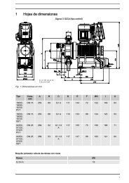
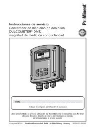
Overview of equipment5 Overview of equipmentOverview of equipment - CHLORIN‐SITU ® <strong>IV</strong> <strong>compact</strong>Fig. 1: Outside parts - without protective cowling4 Brine pump10 Alkali (lye) pump (option)16 Fan membrane cell23 Control unit53 Terminal box54 Fan cooling fins (only type 50)not shown Brine tank with suction lance12
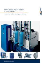
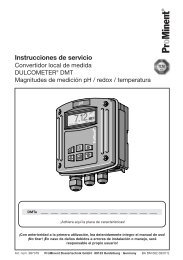
Overview of equipment11121 192150132624789181752022Fig. 2: Inside parts1 Reducing valve2 Water softener unit5 Membrane cell6 Float housing7 Active carbon filter8 Injector9 Alkali (lye) tank (option)11 Manometer12 Valve block13 Plunger17 Chlorine metering point18 Alkali (lye) metering point (option)19 Bleeding20 Drainage21 Circulation water, inlet22 Circulation water, outlet24 Valve injector for chlorine50 Reed switch,internal flow13
Functional description6 Functional description6.1 The electrochemical processCooking salt (NaCl) is dissolved in water in the brine tank to form asaturated solution. This solution is fed into the anodic chamber of amembrane cell. Here the chloride ions (Cl-) of the cooking saltloose their negative charge at the anode to form chlorine, while theNa+ ions migrate through the membrane to the cathodic chamber.At the cathode, water ( 2 O) is electrolytically split into hydrogen (H 2 )and hydroxide ions (OH- ). Sodium hydroxide solution (NaOH) isformed from the sodium and hydroxide ions.Anodic reaction: 2 Cl- → Cl 2 + 2e-Cathodic reaction: 2 H 2 O+ 2 e- → H 2 + 2 OH-The generated chlorine dissolves in water as hypochlorous acid(HOCl) and is sucked out of the system: H 2 O + Cl 2 → HOCl + HCl6.2 SystemThe CHLORINSITU ® <strong>IV</strong> <strong>compact</strong> is connected to a circulation line.Circulation water (10) flows from above into the CHLORINSITU ® <strong>IV</strong><strong>compact</strong> (for numbers - see chapter "Overview of equipment"). Apart is softened in the softener (2). The pressure of the circulatingwater must be reduced to at least 1 bar with the aid of the manometer(11) and the reducer valve (1). The control fills the brine tank(3) with softened water. Brine forms in the brine tank (3). Using thebrine pump (4), the brine is pumped into the anodic chamber (+) ofthe membrane cell (5). The chlorine gas separates out in the membranecell (5). Pumping of fresh brine into the anode chambercauses the depleted brine to be transported through the cell andthen siphoned off with the chlorine gas. The control unit alsoreplaces the water of the cathodic chamber (-).Water is continuously pumped into the cathodic chamber so thatthe concentration is maintained at an optimum within it. The alkali(lye) and the hydrogen are separated at the output of the membranecell (5). The hydrogen is discharged to the outside (19).Optionally the alkali (lye) can be trapped in the alkali tank (9) anddosed into the circulating water as required using the alkali pump(10).The fan (13) is used to cool the membrane cell.14
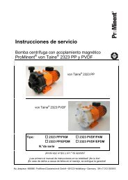
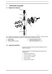
3148 9PMP01LSSLSALTFW15X X7-Functional descriptionPMP02BSTFSBSSDR2PIPC+NAOH + H2CL6H2P_PMA_EL_0033_SWFig. 3: Hydraulic circuit diagram Chlorinsitu <strong>IV</strong> <strong>compact</strong>1 Brine tank2 Booster pump3 Water softener unit4 Membrane cell5 Exhaust air6 Rinsing water7 Drainage8 Injector9 Circulating water15
Functional description6.3 Operating modesIn the standard set-up, the production of the CHLORINSITU ® <strong>IV</strong><strong>compact</strong> is controlled with an external chlorine and pH-controller.The operating mode can be selected in the user menu. There arefour standard operating modes:• Manual mode "M"• On / Off "I"• Pulse signal "F"• Analog signal "A"Additionally, it is possible to equip the CHLORINSITU ® <strong>IV</strong> <strong>compact</strong>with an internal chlorine and pH-control. In the user menu, this islocated under:• Sensor "R"Manual mode "M"WARNING!As no chlorine measurement system is available, overdosingmay occur.The CHLORINSITU ® <strong>IV</strong> <strong>compact</strong> is set to the desired chlorine productionquantity (in percent). As soon as an external release(ENABLE) is available, the desired quantity of chlorine is produced.On / Off "I"The CHLORINSITU ® <strong>IV</strong> <strong>compact</strong> is set to the desired chlorine productionquantity as in manual mode "M". An external, potential-freecontact of a chlorine and pH controller is used to switch the systemon and off.Pulse signal "F"Many chlorine and pH controllers operate with an output signal inthe form of pulses. The maximum number of pulses from the controller(for 100 % production) must be set in the control unit of theCHLORINSITU ® <strong>IV</strong> <strong>compact</strong>.Analog signal "A"The CHLORINSITU ® <strong>IV</strong> <strong>compact</strong> can be connected to an analogstandard signal (4-20 mA). N.B.: 20 mA corresponds to maximumchlorine and pH metering (100%).Sensor "R" (option)The CHLORINSITU ® <strong>IV</strong> <strong>compact</strong> can be equipped with an internalchlorine and pH controller, see the following chapter. Metering bythe system then depends on the chlorine and pH value.6.4 OptionsThe standard version of the chlorine electrolysis system CHLORIN‐SITU ® <strong>IV</strong> <strong>compact</strong> can be expanded with 3 options:• pH correction• Integrated chlorine / pH controller• Booster pumpAll 3 options can also be combined.16
Functional description6.4.1 pH correctionAdditionally, the system has an alkali (lye) metering pump (10), analkali tank (9), in which the alkali from the cell is captured, and analkali metering point (18).The alkali metering pump injects the alkali downstream of theinjector (where the pH value is low) according to the displayed pHvalue in the circulation line. This prevents limescale formation.6.4.2 Integrated chlorine / pH controllerThe option integrated chlorine / pH controller comprises an in-lineprobe housing with a Cl sensor, a pH sensor and a software addon.Here it is also possible to connect an external acid pump, sothat the pH correction operates in both directions.6.4.3 Booster pumpThe system requires a priming pressure of approx. 1.5 bar and circulationcapacity of at least 500 litres per hour. With a primingpressure below 1.0 bar, the water softener does not function correctly,which results in damage to the membrane cell.In most cases a booster pump is required to reach this pressure.17
Requirements for the installation site7 Requirements for the installation siteNOTICE!The ventilation must be operational as soon as thesystem is running.In certain cases, natural ventilation may be sufficient.• It must be possible to seal-off the site of installation to preventaccess.• The climatic data for system and brine tank must correspond tothe values given in the chapter "Technical Data".• The installation site must be ventilated with at least 5 m³/h perm³ room volume.• It must be ensured that the hydrogen can rise upwards into theoutdoor air or into a suitable discharge line.18
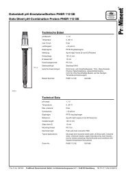
Installation8 Installation8.1 Installation, hydraulicThe CHLORINSITU ® <strong>IV</strong> <strong>compact</strong> must be mountedhorizontally on a level wall.After a week always check that the tubes are still correctlysealed, if necessary tighten the tubes.Refer to the following layout drawing as a guide to thehydraulic installation.Fig. 4: Layout drawing, large figure: Overview of the overall installation with opened CHLORINSITU ® unit, leftabove the brine tank. Small figure: View of its opened front part with the metering pumps.ABCDEFThe hydrogen exhaust duct rising uniformlyupwards to the outside with the supplied EXstickeron the outside of the pipe.A filter insert (GF 192 305 300) with filter mesh(0.5 mm) is recommended.Supply pressure to the booster pump (option) atleast 1 bar.The flow valves with sensors (option)The returning sample water can be fed todrainage or back to the splash water tank.Return to the process water.GHIJKLLead the brine tank overflow into the drainagepipe.Brine tankBooster pump (option)Process water, inputThe second metering pump (option) is providedfor the pH correction option.Brine pump19
Installation8.1.1 System connectionsCAUTION!The hydrogen exhaust dust be fed to the outside. Leadthe hydrogen exhaust duct directly upwards throughthe roof to the outside. In all cases, the hydrogenexhaust duct must rise continuously.Attach the supplied EX-stickers to the exit point of thehydrogen exhaust duct on the roof.The drainage line to the sewerage system must have adiameter of at least Ø40 mm. The system drainage lineand the brine tank overflow may be combined. Thispiping method provides an effective way for checkingwhether the drainage is blocked.8.1.2 Connecting to the circulation lineThe CHLORINSITU ® <strong>IV</strong> <strong>compact</strong> must be connectedto a circulation line, if available, behind the filter.Depending on the size of the pipe, the CHLORINSITU ® <strong>IV</strong> <strong>compact</strong>is connected to the main pipe or a bypass.ParameterInput pressure P1[bar]Pressure differenceat the injector Δp[bar]Water flow throughthe injector [l/h]DesiredvalueMinimumvalue1.5 1.0 61.0 0.8 4.5Maximumvalueapprox. 500 approx. 450 approx.1500It is recommended that for the operating safety of the system, aninput pressure of 1.5 bar is maintained directly prior to the system.The water flow automatically adjusts itself due to the pressure differenceat the injector. If there is no pressure difference relative tothe circulation line, a booster pump must be installed.To attain the pressure difference there are 2 options:1 - With booster pump2 - Without booster pumpThe following drawings show the installation of theCHLORINSITU ® <strong>IV</strong> <strong>compact</strong> in the circulation line.20
Installation8.1.2.1 With booster pumpP3 >=1,5 barP1132P2Fig. 5P_PMA_EL_0031_SW1 Pressure reducer in the system water inlet2 Injector3 Circulation lineComes into consideration for:• Input pressure P1 < 1.3 bar• Back pressure P2 > 0.5 bar8.1.2.2 Without booster pumpP1 > 1,5 bar132P2Fig. 6P_PMA_EL_0032_SW1 Pressure reducer in the system water inlet2 Injector3 Circulation lineComes into consideration for:• Back pressure P2 = max. input pressure P1 - 1 bar21
Installation8.1.3 Brine tankConnect the colour tubes from the brine tank to the connectors atthe valve block, see drawing Ä on page 21.Connect the transparent tube to the suction valve of the brinepump.Fig. 7: Hydraulic installation of the brine tank and valve block1 Water softener drainage (to the sewage system)2 Filling on the brine tank (blue)3 Brine suction to the water softener (red)4 Fill cathode - water8.2 Installation, electricalFor all electrical connections are refer to the wiring diagram - seeappendix.CHLORINSITU ® <strong>IV</strong> <strong>compact</strong> is supplied with a mains cable. It isrecommended that a wall power outlet is installed close to thesystem.22
InstallationIt is recommended that CHLORINSITU ® <strong>IV</strong> <strong>compact</strong> isconnected to a special power circuit, which is rated 16A (at least 6 A).Below the electrical installation of these components is described:1 - Booster pump (option)2 - External controller (if available)3 - Chlorine and pH electrodes for internal measurement (option)4 - Flow switch for flow valve5 - External enable8.2.1 Booster pump (option)The terminal box with a solenoid switch and a motor protectionswitch is mounted between the booster pump and the control unit.Connect protective earth (PE), live (L) and neutral (N) to the terminalsof the motor protection switch.Fig. 8The booster pump is switched on and off via an external enablesignal (ENABLE contact).Once the enable signal is no longer applied, the booster pump continuesto run for a further 10 seconds before stopping.8.2.2 External controller (if available)Connect both the On/Off control and also the Control via a pulseoutput to the corresponding potential-free contact of the chlorinecontroller at the following terminals:23
InstallationFig. 9With alkali (lye) metering only: Connect the appropriate potentialfreecontact of the alkali (lye)/pH controller to the correspondingterminals.For a controller with 4-20-mA output there are two options:1. Connect an active signal from the chlorine controller as follows:Fig. 10With alkali (lye) metering only: Connect an active signal from thealkali/pH controller accordingly.2. Connect a passive signal from the chlorine controller as follows:24
InstallationFig. 11For chlorine the "24 V" terminal of the Chlorinsitu control unit mustbe connected to the "+" terminal of the controller and the "+" terminalon the PCB to the "-" terminal of the controller. The connectors"-" and GND on the PCB must be connected to each other.With alkali (lye) metering only: Connect a passive signal from thealkali/pH controller accordingly.8.2.3 Sensors for integrated chlorine and pH controller (optional)Connect the chlorine sensor and the measuring transducer of thepH sensor to the terminals of the control unit as shown:Fig. 128.2.4 Flow switch of the flow valvesAn internal flow contact (reed switch), which internally monitors theflow, is connected to the FLOW terminals of the control unit.An (external) flow contact of a flow valve can be connected inseries with it:25
InstallationFig. 138.2.5 External enableAn external, potential-free contact issues the release for productionvia the ENABLE terminal of the control unit:Fig. 14This contact can come from a flow contact in the circulation line orfrom another control.WARNING!Warning of chlorine gas dischargeIf the ENABLE terminal is not correctly allocated andthere is no flow in the circulation line, a chlorine bubblecan form in it. When the flow is reconnected, thechlorine bubble is transported into the swimming pool.– Connect a flow contact in the circulation line correctlyto the ENABLE terminal, if no other effectivesolution is applied.8.2.6 Brine tankThe cable for the level switch is located inside the brine tank alongsidethe blue hose. The level switch is a potential-free contact thatis connected to the SALT terminals as follows:26
InstallationFig. 15: BR = brown, BL = blueIf the brine tanks is empty, the level switch contact must be closed.27
Adjustment9 Adjustment9.1 GeneralOperating menu, schematicInfo-levelSTANDBY14:22InputENABLE:ONOFFACT<strong>IV</strong>E - M-Chlorine requirement:100.0%4.16V 22.3A 14:22USER SSTOPSTARTPress Start(with sensor)ACT<strong>IV</strong>E - R-ACT<strong>IV</strong>E - M-ACT<strong>IV</strong>E - M-ESC * Lye requirement:10.0%Acid requirement:10.0%Cl 0.4528C 0H28C 0HpH 7.2Adjustment levelCHOICEUserOKUSERLanguage:GermanFig. 16: Operating diagramEntering the access code– The central menu item ‘USER S’ means userstop) is the linchpin of the operating menu! It isbetween the Info-level and the Adjustment level.Therefore it makes sense to become familiar withits layout.– If you want to jump quickly from the adjustmentlevel to the central menu item ‘USER S’ , press the[ESC] key 2x.Changing the settings* USERLanguage:EnglishUSEROKOKUSERLanguage:GermanLanguage:EnglishFig. 17: Adjustment1. To change the selection in a display, use the [Arrow keys].ð A " * " appears at the top left.2. To save the change, press the [OK] key.ð The symbol " * " disappears.28
Adjustment3. To discard the change, press the [S] key.Access codesThe menus are protected using access codes with the followinglevels:Name Enables ... Access code‘User’‘Manufacturer’Enables functionswhich trained personnelmust use intheir day-to-daywork.For basic settingsduring commissioningand maintenance.999Only known by suitablytrained personnelsuch as customerserviceemployees.INFO-levelThe INFO-level is reached from the ‘USER S’ display by pressingthe key [START/STOP]. It comprises the continuous displays - seeFig. 16:• ‘STANDBY’• Chlorine requirement• Lye requirement• Acid requirement• Chlorine / pH measuring display (only with sensors)The continuous displays also display information about:• Cell voltage• Cell current• Time• Control unit temperature PCB• Operating hours• Chlorine concentration in ppm (only with sensors)• pH value (only with sensors)Status of the system in continuous displaysStatus Explanation Membrane cell andmetering pumpsACT<strong>IV</strong>E Input ENABLE closed On standbySTANDBYNo enable - open ENABLEinputNot on standbyERROR Error Not on standbySTARTUPSetup menu for initial commissioningMenu-controlledmetering pumpsThe status contacts react to the change between ACT<strong>IV</strong>E andSTANDBY or ERROR.The error contacts react to the change between ERROR and whenthe error is cleared.29
AdjustmentADJUSTMENT levelSettings - general approachTo be able to adjust something, the system must first be stoppedand the password available:1. Press the [START/STOP] key.ðThe following appears:USER SPress Stop2. For example, if a setting is to be made in the menu ‘User’ ,press the [OK] key.ðIf password protection is set the following appears:USERPassword03. Using the [DOWN], set the ‘User Password’ (999), confirmby pressing the key [OK] and then press key [S].If no other key is pressed, password settinglapses. Press [ESC] to go back.4. Press the [S] key.ð The following appears:CHOICEUser5. In the ‘Choice’ top level menu use the [Arrow keys] to selectthe desired menu.6. Make the desired settings in the menu. After the last entry,press the [OK] key.ð‘USER S’ re-appears:USER SPress Stop30
Adjustment7. To exit a menu without saving the settings, press the [S] key.ð The following appears:CHOICEUserThe software has the menu structure shown here:CHOICEUserOKPasswordUserCHOICECalibrationOKPasswordMechanicCHOICEMechanicOKPasswordUserCHOICESensor calibr.(only with sensors)OKPasswordUserCHOICEStartupOKPasswordUserCHOICETestOKPasswordMechanicCHOICERinseOKPasswordUserOKRINSERemaining: 600 sCHOICERegenerationOKPasswordUserOKREGENERATIRemaining: 2000 sFig. 18: Overview "Choice"31
9.2 User menuFor a description of the ‘User’ menu - see "Start up".AdjustmentMenu identifiersDescription‘USER’‘CALIBRATION’ *‘MANUFACTURER’‘SENSOR CALIBR.’‘STARTUP’‘TEST’ *‘RINSE’‘REGENERATE’ExplanationUser settings menuCalibration menu for standard signalinputs mAManufacturer settings menuCalibration of the chlorine and pH sensorsSetup menu for initial commissioningTest the components and functionsRinsing the systemRegenerates the water softener* ‘Manufacturer’ password necessaryFunctions of the keysSystemkeyPortrayalin the text[S][START/STOP]FunctionsChange between the continuous displaysor menusContinue without savingStop/Start[OK]Save and / or forward[DOWN]Change the value or selection in the menu[ESC]Back to the top menu ‘Choice’ / Centralmenu item ‘User S’[UP]Change the value or selection in the menu9.3 Menu Calibration mAThis menu is used to calibrate the 4-20 mA inputs - only for trainedservice personnel or upon consultation with the supplier.The menu is only available in English.The ‘Manufacturer’ password is required.32
AdjustmentCALIBRATIONReset cal values1. To reset the existing values, press the [OK] key.ð The following appears:CALIBRATIONApply 4 mA to Cl input2. Apply 4 mA to the chlorine input and confirm with the [OK]key.ðThe following appears:CALIBRATIONApply 4 mA to lye input3. Apply 4 mA to the alkali (lye) input and confirm with the [OK]key.ðThe following appears:CALIBRATIONApply 20 mA to Cl input4. Apply 20 mA to the chlorine input and confirm with the [OK]key.ðThe following appears:CALIBRATIONApply 20 mA to lye input5. Apply 20 mA to the alkali (lye) input and confirm with the [OK]key.ðThe following appears:CALIBRATIONApply new values6. To confirm the new values, press the [OK] key.33
9.4 Menu manufacturerThis menu is intended solely for authorised personnel.AdjustmentCHOICEManufacturer1. To access the menu, press the [OK] key.ðThe following appears:MANUFACTURERPassword0002. Use the [DOWN] key to set the password.3. Press the [OK] key and then the [S] key.ðThe following appears:MANUFACTURERSuction time salt7 minutesThis is where the duration for which the brine pumpdraws up brine is set during regeneration of the watersoftener.4. Set the desired value ([arrow keys]).5. Press the [OK] key and then the [S] key.ðThe following appears:MANUFACTURERRinse time salt20 minutesThis is where the total regeneration time of the watersoftener is set, i.e. the salt suction time plus the rinsetime.6. Set the desired value ([arrow keys]).7. Press the [OK] key and then the [S] key.ðOnly with alkali pump: The following appears:MANUFACTURERAnodes salt DP15 / minuteThe stroke rate for brine is set here for 100% production.34
Adjustment8. Set the desired value ([arrow keys]).9. Press the [OK] key and then the [S] key.ðOnly with alkali pump: The following appears:MANUFACTURERLyes DP14 / minuteThe stroke rate for alkali is set here for 100% alkalirequirementCAUTION!Alkali (lye) cannot be metered for longer thanit is produced for.Enough alkali must remain to neutralise thelow pH value downstream of the injector.10. Set the desired value ([arrow keys]).11. Press the [OK] key and then the [S] key.ðOnly with acid pump: The following appears:MANUFACTURERAcid DP14 / minuteThe stroke rate for acid is set here for 100% acid requirement12. Set the desired value ([arrow keys]).13. Press the [OK] key and then the [S] key.ðThe following appears:MANUFACTURERCath. pulslength420 mSecThis is where the duration per pulse of opening of the solenoidvalve SL for filling the cathode is set.14. Set the desired value ([arrow keys]).15. Press the [OK] key and then the [S] key.ðThe following appears:MANUFACTURERCathode pulse @ 100130 / hourThis is where the number of pulses sent to the solenoidvalve SL per hour is set in order to fill the cathode.35
9.5 Menu Calibrate sensorFor a description of the ‘Calibrate sensor’ menu - see "Start up".Adjustment16. Set the desired value ([arrow keys]).17. Press the [OK] key and then the [S] key.ðThe following appears:MANUFACTURERFilling time remaining6 minutesThe remaining time is set here for which the brine tankshould be filled beyond the filling time.Explanation: As soon as the minimum level in the brinetank is exceeded, a level switch triggers. The control unitopens the solenoid valve FSB in order to fill the brinetank. As soon as the minimum level in the brine tank isexceeded, a post-rinse/flush period starts to count down( ‘Filling time remaining’ ). To completely fill the brine tank,the control unit holds the solenoid valve FSB open forthis ‘Filling time remaining’ .18. Set the desired value ([arrow keys]).19. Press the [OK] key and then the [S] key.ðThe following appears:MANUFACTURERFilling time start5 minutesIf the liquid level in the brine tank falls too low, the liquidlevel must once again reach the specified level within thetime set here. If not the system reports ‘Brine level low’ .20. Set the desired value ([arrow keys]).21. Press the [OK] key and then the [S] key.ðThe following appears:MANUFACTURERWater hardness25 Deg. DThe water hardness to be used for the water softener isset here.(This value specifies the time interval between two regenerationsof the water softener.)22. Set the desired value ([arrow keys]).23. Press the [OK] key and then the [S] key.36
9.6 Menu SetupFor a description of the ‘Setup’ menu - see "Start up".9.7 Menu TestThe ‘Manufacturer’ password is required.9.8 Menu RinseThe system can be rinsed through via this menu.AdjustmentIn the ‘Choice’ menu select the menu ‘Rinse’ ([Arrow keys])and press the [OK] key.ðThe following appears:RINSERemaining600 sOnce the ‘Remaining’ , time has elapsed, the control jumps to thecentral menu item ‘USER S’ .9.9 Menu RegenerateThis menu is used for the manual regeneration of the water softener.In the ‘Choice’ menu select the menu ‘Regenerate’([Arrow keys]) and press the [OK] key.ðThe following appears:REGENERATERemaining:2500 sOnce the ‘Remaining’ , time has elapsed, the control jumps to thecentral menu item ‘USER S’ .37
Start up10 Start upTo ensure subsequent trouble-free operation, we recommendstart up of the system by the supplier.The following steps are necessary:1 - Prepare brine2 - Check conditions3 - Only for initial start up: Run through the ‘SETUP’ menu4 - Run through the ‘USER’ menu5 - Check the operating parameters6 - Only with sensors: Calibrate sensors7 - Rinse water softener (optional)The table with the factory settings is at the end of the operatinginstructions.10.1 Prepare brineNOTICE!Adhere to the "requirements relating to the startingsubstances" - see below.– Optimally, prepare the brine the preceding evening,as it takes a certain time until the brine hasattained the correct concentration.– Preferably use softened water. If softened water isnot available, then for the initial set up, tap watermay be used.Fill the brine tank with at least 2 bags of salt (each 25 kg) andwater up to approximately 40 cm above the bottom.10.1.1 Requirements applying to the starting substancesSaltOptimally a so-called vacuum salt is most suitable.For human use, it must be of food-quality.To ensure a long service life for the membrane cell salt with as fewimpurities as possible should be used.Use regeneration salt with:Minimum grain size0.38 mmAnti-clogging agent max.20 ppm38
Start upThe quality must correspond to quality B for human use in accordancewith the latest version of DIN EN 973:NaCl, min.99.4 % by weightAdditionally, these special limit values of van den Heuvel apply forelectrolysis systems:Property Value UnitCalcium, max. Ca+ 15-70 ppmMagnesium, max. Mg+ 15-70 ppmBromine Br 4 ppmArsenic As 10 ppmAntimony Sb 10 ppmCadmium Cd 10 ppmChromium Cr 10 ppmLead Pb 10 ppmMercury Hg 10 ppmNickel Ni 10 ppmSelenium Se 10 ppmCarbonate Na 2 CO 3 150 ppmSulphate Na 2 SO 4 40 ppmIron Fe 4 ppmCopper Cu 0.1 ppmIodine I 4 ppmSilicate SiO 2 40 ppmAluminium Al 0.4 ppmInsoluble substances, max. - 100 ppmNOTICE!An incorrect salt can destroy the membrane cell.In cases of doubt, van den Heuvel will be happy toadvise you:For contact data see the published by information.WaterUse fresh potable water according to the existing WHO guidelines.Property Value UnitWater hardness, max.* 45 °dH* If the water hardness is higher, contact the supplier.39
Start up10.2 Check conditionsNOTICE!Before start up of the Chlorinsitu ® <strong>IV</strong> <strong>compact</strong>, a seriesof points must be checked:No. Check point OK?1 Brine tank filled with at least 2 bags of salt (each25 kg) and water up to approximately 40 cm abovethe bottom2 Lines are clean and free from swarf or chips3 Water pressure downstream of the reducing valveis between 1 and 1.6 bar4 Hydrogen exhaust duct is routed to the outside andan Ex- sticker has been stuck on5 Room ventilation is adequate6 Drainage line to the sewer system is sufficientlylarge and has a sufficient drop7 Water hardness upstream and downstream of thewater softener8 Connection of the ENABLE input is correct9 Connection of the control signal (Option) is correct10.3 Run through the SETUP menuOnly required for the first system start.1. Prior to the system start the conditions for this must bechecked, see Ä Chapter 10 ‘Start up’ on page 38.2. Before the system is connected to the mains voltage, theshut-off valve in the circulation line must be opened.3. Check the supply voltage.40
Start up4. Insert the plug in the power socket.ðIf the ENABLE contact is closed, the booster pump starts(optional).If the system is connected to the mains voltage for thefirst time, the LCD screen automatically shows the‘Setup’ menu.SETUP 1/4Salt Level ok?OK= Yes ESC= EndIf problems arise during the first system start,press the [ESC] key: the system stops( ‘USER S’ ).After clearing the problem, briefly disconnectthe system from the mains voltage: the‘SETUP’ menu reappears.5. To confirm that the brine tank is correctly filled with salt andwater, press the [OK] key.ðThe next display appears:SETUP 2/4Anode filled?OK= Yes ESC= EndSimultaneously, the brine pump pumps brine at its maximumstroke rate into the anode chamber and the tubes.Therefore:Fig. 19: Pump bleed valve6. While the pump is running, bleed the suction line. To do thisscrew open the bleed valve (in the anticlockwise direction).41
Start up7. After bleeding, screw the bleed valve in until it is correctlyclosed (clockwise direction).Fig. 20: Necessary liquid level in the tube to the membrane cell,anode side.8. Now check that the pump on the anode side of the membranecell has completely filled the tube to the membrane celland that liquid and bubbles can be seen at the output of theanode side.This may take several minutes.9. As soon as the tube is full, press the [OK] key.ðThe next display appears:SETUP 3/4Cathode filled?OK= Yes ESC= EndSimultaneously the cathode top-up valve FSB opens, sothat softened water fills the cathode chamber of themembrane cell.42
Start upFig. 21: Necessary liquid level on the cathode side10. Now check that the tubes from and too the cathode side ofthe membrane cell have filled completely. Duration approximately5 s.If fitted: The water level in the alkali storage tank must alsobe visible.11. If fitted: Bleed the alkali pump and its suction hose, as for thebrine pump.12. As soon as these parts are full and bled, press the [OK] key.ðThe next display appears:SETUP 4/4Operational?OK= Yes ESC= EndThe cathode top-up valve FSB closes simultaneously.13. If the system is considered as operational, press the [OK]key.ðThe following appears:USER SPress STARTThe menu ‘Setup’ is completed.14. If the system is started after a long shutdown, the water softenermust be manually regenerated - see chapter 10.For the first system start-up, the water softener isregenerated in the factory.The menu ‘SETUP’ no longer needs to be run through.43
Start up10.4 Run through the USER menuTo start up the control, run through the ‘User’ menu.Prior to the start of the system, an operating mode must beselected. "Manual" operating mode with 0 % is preset.USER SPress START1. Press the [S] key.ð The following appears:CHOICEUser2. Press the [OK] key.ðThe following appears:USERPassword03. Using the [DOWN] key set "999" and press the [OK] key.4. Press the [S] key.ðThe following appears:USERLanguageGerman5. If necessary set the language using the [arrow keys] andpress [OK].6. Press the [S] key.ðTypically the following appears:USERCl input signalManual.The composition in the ‘User’ menu may depend on the orderedinput signal. Therefore the options offered are explained below oneafter the other:44
Start up1 - Manual mode "M"2 - On / Off "I"3 - Pulse signal "F"4 - Analog signal "A"5 - Sensor "R"10.4.1 Manual operating mode ("M")USERCl input signalManual1. Press the [OK] key and then the [S] key.ðThe following appears:USERCl manual50 %The display indicates the set chlorine production, relativeto the maximum possible production.2. Enter the desired value ([arrow keys]) and press the [OK]key.3. Press the [S] key.ðThe following appears:USERpH (Lye) signalManual4. Press the [OK] key and then the [S] key.ðThe following appears:USERLye manual50 %The display indicates the set alkali production, relative tothe maximum possible production.5. Enter the desired value ([arrow keys]) and press the [OK]key.6. Press the [S] key.45
Start up10.4.2 Operating mode On / Off ("I")1. Press the [S] key.ðThe following appears:USERCl input signalOn/Off2. Press the [OK] key and then the [S] key.ðThe following appears:USERCl manual50 %The display indicates the maximum possible chlorine production.3. Enter the desired value ([arrow keys]) and press the [OK]key.4. Press the [S] key.ðThe following appears:USERpH (Lye) signalOn/Off5. Press the [OK] key and then the [S] key.ðThe following appears:USERLye manual50 %The display indicates the maximum possible alkali production.6. Enter the desired value ([arrow keys]) and press the [OK]key.7. Press the [S] key.46
Start up10.4.3 Operating mode pulse signal ("F")1. Press the [S] key.ðThe following appears:USERCl input signalPulse2. Press the [OK] key and then the [S] key.ðThe following appears:USERChlorine pulse @ 100 %180 pulseThe display indicates the pulse frequency for maximumchlorine demand.3. Enter the desired value ([arrow keys]) and press the [OK]key.4. Press the [S] key.ðThe following appears:USERpH (Lye) signalPulse5. Press the [OK] key and then the [S] key.ðThe following appears:USERpH pulse @ 100 %180 pulseThe display indicates the pulse frequency for maximumalkali demand.6. Enter the desired value ([arrow keys]) and press the [OK]key.7. Press the [S] key.47
Start up10.4.4 Operating mode analog signal 4–20 mA ("A")1. Press the [S] key.ðThe following appears:USERCl input signal4-20 mAThe display indicates the current range for chlorinedemand.2. Press the [S] key.3. Press the [OK] key.ðThe following appears:USERpH (Lye) signal4-20 mAThe display indicates the current range for alkali demand.4. Press the [S] key.10.4.5 Operating mode sensor ("R")The "Sensor" selection is used for control with internal measurement.To do this an additional software add-on is necessary. If thisis not available, "Sensor" can be selected, however the additionalmenus do not appear.1. Press the [S] key.ðThe following appears:USERCl input signalSensor2. Press the [OK] key and then the [S] key.ðThe following appears:USERCl Sens. range0...2 ppm3. Using the [DOWN] key select the measuring range of thesensor used and press the [OK] key.48
Start up4. Press the [S] key.ðThe following appears:USERCl Sens. setpoint1.00 ppm5. Adjust the desired setpoint for the chlorine control using the[arrow keys] and press the [OK] key.6. Press the [S] key.ðThe following appears:USERCl sensor P-Band0.30 ppm7. Adjust the desired P-band (Proportional band) for the setpointfor the chlorine control using the [arrow keys] and pressthe [OK] key.With a setpoint of 1.00 ppm and a P-band of 0.30ppm, it follows that with a measured value of0.70 ppm, the chlorine dosing is a maximum.8. Press the [S] key.ðThe following appears:USERpH (Lye) signalpH sensor9. Press the [OK] key and then the [S] key.ðThe following appears:USERpH sens. setpoint7.010. Adjust the desired setpoint for pH control using the[arrow keys].49
10.4.6 Other parameters1. After the operating mode settings appears:Start up11. Press the [OK] key and then the [S] key.ðThe following appears:USERpH sens. T range0.112. Adjust the desired T-band (dead zone, neutral range) for thesetpoint for the chlorine control using the [arrow keys].With a setpoint of pH 7.0 and a T-band of 0.1ppm, it follows that with a measured valuebetween pH 6.9 and 7.1 no alkali will be dosed.13. Press the [OK] key and then the [S] key.ðThe following appears:USERpH sens. P range0.614. Adjust the desired P-range (proportional band) for the pHcontrol setpoint using the [arrow keys].With a setpoint of pH 7.0 and a P-band of 0.6, itfollows that with a measured value of pH 6.4, thealkali dosing is a maximum.If fitted: Acid dosing is maximum at a measuredvalue of pH 7.6.15. Press the [OK] key and then the [S] key.USERRegenerate hr03 Clock2. Using the [arrow keys] set the time at which the water softeneris to be automatically regenerated.03.00 a.m. is preset.50
Start up3. Press the [OK] key and then the [S] key.ðThe following appears:USERClock Time Hours14 Hour4. Using the [arrow keys] set the hours of the current time andpress the [OK] key.5. Press the [S] key.ðThe following appears:USERClock Time Minutes43 Minute6. Using the [arrow keys] set the minutes of the current timeand press the [OK] key.7. Press the [S] key.Summertime must be set manually.10.5 Check the operating parameters1. Press the [START/STOP] key.ðThe system is now working and the continuous displayappears:ACT<strong>IV</strong>E-R-Cl requirement: 100 %5.20V 25.0A 14:43Control takes place using sensor = "R".Chlorine demand is 100 %.Voltage at the membrane cell is 5.20 V.The current through the membrane cell is 25.0 A.The time is 14:43.51
10.6 Calibrate sensors1. [Start / Stop] the system using the Start/Stop key.Start up2. Press the [S] key.ðThe continuous display appears:ACT<strong>IV</strong>E-R-Lye requirement: 30 %28°C 0hThe alkali requirement is 30%.The temperature in the control unit is 28 °C.The number of system operating hours is 0 h.3. Without "Internal Measurement": the system is now in operation.4. With "Internal measurement" press the [S] key.ðThe continuous display appears:ACT<strong>IV</strong>EAcid requirement: 0 %28°C 0hThe acid requirement is 0 %.5. Press the [S] key.ð The continuous display appears.ACT<strong>IV</strong>EFor the first start, it takes some 1 ... 2 hours untilthe system attains the normal operating parameters.-R--R-Chlorine: 0.40pH 7.1The measured chlorine concentration is 0.40 ppm.The measured pH value is 7.1.6. If fitted: Calibrate the chlorine and pH sensors.ðThe following appears:USER SPress START52
10.6.1 calibration pHPress the [OK] key.Start up2. Press the [S] key.ð The following appears:CHOICEUser3. Use the [DOWN] key to change to the menu ‘Sensor calib.’ .4. Press the [OK] key.ðThe following appears:SENSORSCalibrate pHðThe following appears:SENSORS1 pt cal.53
Start up10.6.1.1 1 point calibrationOKCHOICESensor calibr.SENSORpH sensor cal.OKSENSORSingle point cal.OKSENSORActual value7.0OKSENSORpH sensorRe-calibrate?SENSORpH sensorgoodSENSORpH sensorsatisf.OKOKOKB04501. Press the [OK] key.ðThe following appears:SENSORSActual value10.02. Measure the pH value of the sample water.3. Enter the pH value using the ([arrow keys]) and press the[OK] key.ðThe following appears:SENSORSpH calibrateGoodThe following table explains the messages.4. If you do not want to ‘Recalibrate?’ press the [OK] key andthen [ESC].5. In all other cases, press the [OK] key.54
Start upMessage Cause Remedy‘Good’ The sensor is OK. -‘Satisfactory’‘Re-calibrate?’The sensor is still inthe tolerance range.The calibration isfaulty..The sensor is defective.Time to get a newsensor.Repeat the calibration.Carry out a 2 pointcalibration.Procure a newsensor.10.6.1.2 2 point calibrationCHOICESensor calibr.OKSENSORpH sensor cal.OKSENSORSingle point cal.SENSORTwo point cal.OKSENSORpH Buffer 1 (4)OKSENSORWait time!*****SENSORpH Buffer 2 (10)OKSENSORWait time*****SENSORpH sensorRe-calibrate?SENSORpH sensorgoodSENSORpH sensorsatisf.OKOKOKB045155
Start upThe 2-point calibration can be carried out if the 1-point calibrationhas failed. The 2-point calibration is always more precise and canalso be carried out directly.Materials required:Quality buffer pH 4 and pH 10 (included in the scope of supply)SENSORS2 pt cal.1. Press the [S] key to select a 2-point calibration.2. Press the [OK] key.ðThe following appears:SENSORSpH Buffer 1 (4)3. Shut-off the sample water.4. Unscrew the measuring transducer from the pH sensor.5. Remove the pH sensor.6. Rinse the pH sensor with distilled water.7. Carefully dab the pH sensor dry with a cloth (grease-free,lint-free).8. Screw the measuring transducer back onto the pH sensor.9. Immerse the pH sensor in quality buffer 1 = pH 4, gently stirthe buffer with it and press the [OK] key.ðThe following appears:SENSORSWait time!**************10. Hold the pH sensor in the quality buffer - without touching thewall, until this display appears:SENSORSpH Buffer 2 (10)56
Start up11. Rinse-off the pH sensor, carefully dab, immerse in the qualitybuffer 2 = pH 10, gently stir the buffer with it and press the[OK] key.ðThe following appears:SENSORSWait time!**************12. Hold the pH sensor in the quality buffer - without touching thewall, until this display appears:SENSORSpH slope 0.00pH 4.00ðThe display shows the slope and the zero point.(These values tell the expert something about the state ofthe sensor.)13. Press the [OK] key.ðThe following appears:SENSORSpH calibrateGoodThe following table explains the messages.14. If you do not want to ‘Recalibrate?’ press the [OK] key andthen [ESC].15. In all other cases, press the [OK] key.16. Re-install the pH sensor.17. Re-open the stopcocks for the sample water, first dischargethen feed.Message Cause Remedy‘Good’ The sensor is OK. -‘Satisfactory’‘Incorrect’ and then‘Recalibrate?’The sensor is still inthe tolerance range.The calibration isfaulty.The sensor is defective.Time to get a newsensor.Repeat the calibration.Procure a newsensor.57
Start upCHOICE10.6.2 Chlorine calibrationOKSensor calibr.SENSORpH sensor cal.SENSORChlorine sensor cal.OKSENSORActual value1.0OKSENSORChlorine sensorFalseSENSORChlorine sensorgoodSENSORChlorine sensorsatisf.OKSENSORChlorine sensorRe-calibrate?OKOKOKESCB04491. [Start / Stop] the system using the Start/Stop key.ðThe following appears:USER SPress START2. Press the [S] key.ðThe following appears:CHOICEUser3. Use the [DOWN] key to change to the menu ‘Sensor calib.’ .4. Press the [OK] key.ðThe following appears:SENSORSCalibrate pH5. Press the [S] key.ðThe following appears:SENSORSCalibrate Chlorine58
Start upThe chlorine sensor calibration is always a 1-point calibration.NOTICE!– Please also observe the operating instructions forthe chlorine sensor and the in-line probe housing.– The slope has to be re-calibrated at regular intervalsto ensure perfect operation of the chlorinesensor.Calibrating the sensor every 3-4 weeks sufficeswith swimming pool or potable water.– Avoid incorrect dosing, which could be caused byair bubbles in the sample water! Air bubbles, whichadhere to the membrane of the sensor, can resultin too low a reading and thus lead to overmetering.– Chlorine must be continuously present in thesample water (approx 0.5 mg/l) for the wholeperiod.Otherwise the measuring system cannot calibrate.– Please note the pertinent national guidelines forcalibration intervals.1. Take a water sample at the in-line probe housing.2. Immediately afterwards, determine the chlorine content of thesample water with a photometer and a suitable measuringset, (e.g. DPD 1 for free chlorine (CLE sensor))3. Press the [OK] key.ðThe following appears:SENSORSActual value10.04. Enter the chlorine content using the ([arrow keys]) and pressthe [OK] key.ðThe following appears:SENSORSChlorine calibrateGoodThe following table explains the messages.5. If you do not want to ‘Recalibrate?’ press the [ESC] key.6. In all other cases, press the [OK] key.59
Start upMessage Cause Remedy‘Good’ The sensor is OK. -‘Satisfactory’‘Re-calibrate?’The sensor is still inthe tolerance range.The calibration isfaulty.The sensor is defective.Time to get a newsensor.Repeat the calibration.Procure a newsensor.10.7 Rinse water softenerAs soon as the softener fills for the first time, green-brown waterflows into the brine tank. If this is not desirable, rinse through thesoftener:Fig. 22: The sampling unit in the brinetank1. Release the blue hose (1) from the sampling unit and leadinto a bucket.2. Then pull the grey cap (2) off the sampling unit and pull thelevel switch out of the brine.ðThe system starts to fill, as soon as it is in the status‘Active’ .3. Press the grey cap (2) back on to the sampling unit.4. It may be necessary to repeat this step, until clear watercomes out of the blue hose (1).ðThe softener is rinsed through.5. Re-connect the hose (1) to its hose coupling.60
11 During useInspect the system daily, see the "Maintenance" chapter.During useCAUTION!The membrane cell can be damaged irreparably.Top up only with salt (NaCl) that conforms to the specifications- see chapter "Start up".61
12 MaintenanceFor optimum operation, the following measures must be observed:MaintenanceWARNING!For maintenance work always use suitable protectivemeasures according to the supplier's manual.CAUTION!Important! Check the system to prevent seriousdamage. Each defect that is detected early-on can beeasily rectified without endangering system reliability.Only a trained service team may carry out annual andthree-yearly maintenance.Before working on the system, it must be rinsedthrough. Please refer to the "Adjustment" - "Rinse"chapter for instructions on rinsing the system so that itis free from chemicals.IntervaldailyMaintenance workCheck the entire system for leaks, discolouration, unusual noises and error messagesat the operating panel.Report any leaks immediately.Compare the chlorine value, which is displayed by the control and, if alkali dosingis available, the pH value with those of the tank water or, if available, the valuesat the in-line probe housing with the sensors.If necessary, add salt to the brine tank.Rule of thumb: It must be possible to see salt from the water.If the system stops working, check whether it is a normal control stop or if anexternal Enable condition exists ‘Standby’ ).If an unusual situation occurs, then after a short while check the system again. Ifthe situation persists, inform the supplier.Every 2 weeks Check the softener, see Ä ‘Check the water softener’ on page 63.Every 3 - 4 weeksAnnuallyEvery 3 yearsIf fitted: Calibrate the chlorine sensor, see chapter "Start up" - "Sensor calibration".If fitted: Calibrate the pH sensor, see chapter "Start up" - "Sensor calibration".Supplier maintenance in accordance with the maintenance manual.Standard maintenance kits can be obtained for this.Supplier maintenance in accordance with the maintenance manual.Standard maintenance kits can be obtained for this.62
MaintenanceCheck the water softenerCAUTION!Severe damage at the membrane cell is possibleIf the softener does not function correctly, limescaledeposits may cause severe damage to the membranecell.– Also check the water hardness of the water fromthe softener.1. To take a water sample from the softener proceed as forrinsing of the softener - see chapter "Start up" - "Rinsing thewater softener".2. Check that the water hardness of this water is 0 °dH.To measure the water hardness, the measuringkit supplied by ProMaqua can be used - see"Ordering information" for the order no..63
Troubleshooting13 TroubleshootingWARNING!Chlorine, sodium hydroxide solution, hydrogen andsodium hypochlorite can be released from the system.Do not forget this!WARNING!The described activities must only be carried out theauthorised personnel.Errors without error messagesFault description Cause RemedyLCD screen is dark (nocurrent)No chlorine present inthe process waterFuse defectiveIncorrect chlorine measurementCurrent value* at max. 5.2 Vis low, although chlorine isrequestedCurrent value* at max. 5.2 Vis low, although chlorine isrequestedCurrent value* at max. 5.2 Vis low, although chlorine isrequestedNo flow via the injector intothe systemStandby, no enable signalFirst check the fuse of the power supply andthen if necessary the fuses in the control unit.With external control: Check the sensors, calibrationand control settings. With internal control:Calibrate the sensorsCheck the supply of brine (is the brine tankfull?).Bleed the brine pumpCheck the solenoid valve "Top-up cathode"(SL). If it does not open correctly, no liquid canflow into the cell.Check the water hardness. With hard water,the cell may have scaled up.Check the input pressure and, if necessary, thebooster pumpCheck the external enable contact* With 5 V electrode voltage, the current values are in the range:With Cl requirement of 25 g system 50 g systemapprox. 25 % 6.1 A 12.5 Aapprox. 50 % 12.5 A 25 Aapprox. 100 % 25 A 50 AErrors with error messagesFault description Cause Remedy‘Not active’No enable - the system ison standbyCheck the external ENABLE contact.‘Brine level low’ Liquid level switch Check the liquid level switch in the brinetank.64
TroubleshootingFault description Cause RemedyLeaksCheck the hoses.Water pressure at thesoftenerCheck the reducing valve and the softener.‘Error - no liquid flow’ Reed switch in the device Check the reed switch for internal flow.‘Overtemperature’ (PCB is toohot)Booster pump / circulationWith external measurement:Flow in the in-lineprobe housingRoom temperatureFanCheck the booster pump and the flow inthe circulation line.Check the flow in the in-line probehousing.Check the room humidity.Check the fan in the control unit and, fortype 50 only, the two fans at the coolingfins of the control unit.Other error messages are described in the chapter"Adjustment" - "pH calibration" and "Chlorine calibration".65
Decommissioning and disposal14 Decommissioning and disposal1. If an alkali tank is fitted: Carefully empty the alkali tank viathe alkali pump, turn the multifunctional switch to "Test".2. Refer to the "Adjustment" - "Rinse" chapter for instructions onrinsing the system.3. Remove the system plug the power socket.4. Rinse the alkali away into the drain with two buckets of water.During decommissioning and disposal of the system,observe the relevant, national disposal instructions.66
Substances produced15 Substances producedChlorine gasProperty Unit ValueICSC / CAS 0126 / 7782-50-5Risk phrases R: 23-36/37/38-50Safety phrases S: 1/2-9-45-61Boiling point °C -34Flash point Non-flammableTemperature class Not applicableDensity relative toair2.47Absolute density kg/m³ 3.18Molar mass g/mol 70.9Vapour pressure bar(a) 7Colour yellow-greenHydrogenProperty Unit ValueICSC / CAS 0001 / 133-74-0Risk phrases R: 12Safety phrases S: 2-9-16-33Boiling point °C -253Flash point Flammable gasIgnition temperature °C 560Temperature class T1Relative density relativeto air0.07Absolute density kg/m³ 0.08908Molar mass g/mol 2Explosive limits(LEL - UEL)Vol.-% in air 4 ... 76Colour ColourlessSodium hydroxideProperty Unit ValueICSC / CAS 0360 / 1310-73-2Risk phrases R: 35Safety phrases S: 1/2-26-37/38-45Concentration inC<strong>IV</strong>% 10 ... 2067
Substances producedProperty Unit ValueConcentration inC<strong>IV</strong>Boiling point (solution)g/l 100 ... 200°C 110 ... 120Flash point Non-flammableTemperature class Not applicableDensity kg/m³ 1.2 ... 1.36Molar mass g/mol 40.0Colour Colourless68
Technical data16 Technical dataSize Type 25 Type 50Output [g/h] 25 50Mains voltage [VAC] 230± 5 % 230 ± 5 %Mains frequency [Hz] 50 50Power consumption [kW] 0.11 0.22Control fuse protection [A] 6 6Mains power lead fuse protection [A] 16 16Salt consumption [g/h] 65 130Process water pressure [bar] 1 ... 6 1 ... 6Water consumption [l] 1.5 3Dimensions LxBxH [mm] 590 x3 55 x 650 590 x 355 x 650Volume brine tank [l] 120 120Connector water circulation [Ø mm] 20 20Connector sewage system [Ø mm] 20 20Connector hydrogen exhaust duct [Ø mm] 20 20Drainage quantity per regenerationRinsing water [l] 25 25Brine [l] 1 1Drainage quantity at 100 % productionMaximum alkali [l/h] 1.3 2.6Hydrogen (l/h) 10 20Electrical inputsInputContact (digital) inputsAnalog inputsPropertypotential-freeactive or passiveElectrical outputsOutputStatus contactsError contactsProperty230 VAC / 2 A230 VAC / 2 A69
Technical dataAmbient conditionsData Value UnitAmbient temperature, min. +10 °CAmbient temperature, max. +35 °CMaximum air humidity * 92 % rel.humidity* non-condensingMiscellaneous: Protect against sunlightSound pressure levelThe sound pressure level is < 70 dB (A) at maximum power(without the booster pump)70
Wiring diagrams17 Wiring diagramsWiring diagram system+ AnodeMEMBRANE CELLERROR CONTACTSSTATUS CONTACTSCONTACT FROMFILTER FLOWCONTACT FROM FLOWSWITCH IN DEVICECONTACT FROMBRINE LEVELMETERING PUMPS+-+ Anode- Cathode- CathodeError StatusNCPNONCPNOENABLEGNDFLOWGNDSALTGNDGNDGNDGNDSALTPUMPACIDPUMPLYEPUMPEXTERNAL CONNECTORSEENEXT PAGEGND- 4-20mA+ 4-20mA24 VGND- 4-20mA+ 4-20mA24 VSET CL SET LYEVALVE BRINETANK FILLVALVE BRINE SUCTION/REGENERATEVALVE TOWASTE WATERVALVE REFRESHLYE EDGERESERVE2 2 2 2 21 1 1 1 1+ FSB- FSB+ SS- SS+ DR- DR+ SL- SL+ USER- USEREXTERNAL RELAY230 VACL/N/PEMAIN-SUPPLYBOOST-PUMPDOSING PUMP ADOSING PUMP BP_PMA_EL_0028_SWPENL71
Wiring diagramsExternal connector terminalsA4-20 mA Aktivsignal B 4-20 mA Passivsignal+-+-GND- 4-20mA+ 4-20mA24 VGND- 4-20mA+ 4-20mA24 VSET CL SET LYE+-+-GND- 4-20mA+ 4-20mA24 VGND- 4-20mA+ 4-20mA24 VSET CL SET LYECImpulseDEin / AusGNDGND- 4-20mA+ 4-20mA24 VGND- 4-20mA+ 4-20mA24 VSET CL SET LYE- 4-20mA+ 4-20mA24 VGND- 4-20mA+ 4-20mA24 VSET CL SET LYEP_PMA_EL_0029_SW72
Ordering Information18 Ordering InformationpH quality buffer solutionsBuffer Content [ml] Part no.Buffer pH 4.0, red colour 50 506251250 791436Buffer pH 10.0, blue colour 50 506255250 791438pH measuring instrumentPart no.Photometer Dulcotest DT1B 1039315Water hardness measuring kitPart no.Water hardness measuring kit 50550573
19 Factory settingsMetering pumpsFactory settingsParameter For type 25: For type 50: UnitBrine pumpstroke lengthAlkali (lye)pump strokelength100 100 %80 80 %User menuParameter For type 25: For type 50: UnitPassword 999 / --- 999 / ---Language as ordered as orderedCl input signal Manual * Manual *Cl manual 0 0 %Cl sensor range 0 ... 2 0 ... 2 ppmCl sensor setpoint 0.9 0.9 ppmP-Band Cl sensor 0.3 0.3 ppmCl pulse @ 100% 180 180 1/minpH (Lye) signal Manual * Manual *pH manual 0 0 %pH sensor setpoint 7.2 7.2pH sensor T-band 0.1 0.1pH sensor P-band 0.5 0.5pH pulse @ 100% 180 180 1/minTime of regener. 03:00 03:00 Time* with integrated chlorine and pH controller SensorMFG menuParameter For type 25: For type 50: UnitPassword --- ---Salt suction time 7 7 minSoftener rinse time 20 20 minAnode pulse @100%14 28 1/minLye pulse @ 100% 13 26 1/minAcid pulse @ 100% 13 26 1/minCath. pulslength 420 520 msCathode pulse @100%130 180 1/h74
Factory settingsParameter For type 25: For type 50: UnitBrine tank filling time 6 6 minBrine tank regeneration5 5 minWater hardness 25 25 °D75
EC Declaration of Conformity20 EC Declaration of Conformity-Original-CE- Declaration of Conformity IIAWe,Van den Heuvel Watertechnologie bvGlashorst 114 P.O. Box 713925 BV Scherpenzeel (Gld) 3925 ZH Scherpenzeel (Gld)NetherlandsNetherlandsTel.: +31 (0)33 2778600Fax :+31 (0)33 2778399URL: www.vdhwater.nlEmail: info@vdhwater.nldeclare under sole responsibility that the product:Chlorinsitu ® -<strong>IV</strong> Compact,Serial number:see Type plate on installationto which this declaration pertains, is in conformity with the provisions of the following directives:Machinery DirectiveEMC DirectiveThe part of the Low-voltage Directiveis followed according appendix nr. 1.5.1of the Machinery Directive 2006/42/EC2006/42/EC2004/108/EC2006/95/ECExplosion Protection Directive ATEX 95and with the associated international and national harmonized standards:Electrical safety NEN 1010 and IEC/ EN 60204-1Risk assessment NEN 1050EMC IEC/ EN 61000-6.1- 6.2Classification of hazardous areas NPR 7910-1Technical Construction Dossier:E. BrinkTechnical documentation Glashorst 114collected and guarded at:3925 BV ScherpenzeelLocation and date: Scherpenzeel, 08-05-2012Signed by authorized representative:E. Brink, Director76
Index21 Index1, 2, 3 ...1 point calibration................................................. 542 point calibration................................................. 554-20 mA................................................................ 48AAbout this product.................................................. 6Access codes....................................................... 29Acid pump............................................................ 17ACT<strong>IV</strong>E................................................................ 29Active carbon filter................................................ 13Adjustment........................................................... 28ADJUSTMENT level............................................. 30Alkali (lye) metering point..................................... 13Alkali (lye) pump............................................. 12, 14Alkali (lye) tank..................................................... 13Ambient conditions........................................... 7, 70Analog signal........................................................ 48Analog signal "A".................................................. 16BBleeding............................................................... 13Block diagram, changing the settings.................. 28Block diagram, operating menu........................... 28Booster pump............................... 15, 17, 19, 20, 23Brine pump..................................................... 12, 14Brine tank................................................. 14, 15, 26Brine tank, installation.......................................... 22Buffer solutions.................................................... 73Bypass................................................................. 20CCalibration, sensors............................................. 52Calibration mA...................................................... 32calibration pH....................................................... 53Cell current..................................................... 29, 51Cell voltage.................................................... 29, 51Changing the settings, block diagram.................. 28Check the operating parameters.......................... 51Check the water softener..................................... 63Chlorine calibration.............................................. 58Chlorine concentration................................... 29, 51Chlorine gas........................................................... 9Choice.................................................................. 30Choice menu, overview........................................ 31Circulation line...................................................... 20Circulation water, inlet, outlet............................... 13Continuous displays............................................. 51Controller with 4-20 mA output............................. 24Control unit........................................................... 12Control unit temperature PCB........................ 29, 51Control via a pulse output.................................... 23Control via On/Off output..................................... 23Current values, table............................................ 64DDevice identification............................................... 5Disposal............................................................... 66Disposal line........................................................... 9DR, valve.............................................................. 22Drainage............................................... 9, 13, 15, 20During use............................................................ 61EElectrochemical process...................................... 14Emergency........................................................... 11ENABLE............................................................... 71Enable, external................................................... 26ENABLE terminal................................................. 26ERROR.......................................................... 29, 64Error contacts....................................................... 71Error messages.................................. 54, 55, 58, 64Exhaust air........................................................... 15Explosion safety................................................... 10External connector terminals................................ 72External controller, input...................................... 23External enable.................................................... 26FFactory settings.................................................... 74Fan cooling fins.................................................... 12Fan membrane cell.............................................. 12Fill brine tank........................................................ 40Filling time remaining........................................... 34Filling time start.................................................... 34Filter insert........................................................... 19Float housing........................................................ 13FLOW................................................................... 71Flow, internal........................................................ 13Flow contact......................................................... 25FLOW terminal..................................................... 25Flow valve............................................................ 19FSB, valve............................................................ 22Functional description.......................................... 14Functions of the keys........................................... 32GGeneral safety notes.............................................. 9HHydraulic circuit diagram...................................... 15Hydrogen................................................................ 977
IndexHydrogen exhaust duct.................................. 19, 20IINFO-level............................................................ 29Information in the event of an emergency............ 11Injector........................................................... 13, 14Installation, electrical............................................ 22Installation, hydraulic............................................ 19Installation site..................................................... 18Integrated chlorine / pH controller........................ 17Integrated chlorine and pH controller..................... 5Intended use.......................................................... 8KKeys, functions..................................................... 32LLayout drawing..................................................... 19Level switch.......................................................... 26MMaintenance......................................................... 62Manometer........................................................... 13Manual mode....................................................... 45Manual mode "M"................................................. 16Manufacturer, menu............................................. 34Membrane cell................................................ 13, 14Menu manufacturer.............................................. 34Menu structure..................................................... 31Motor protection switch........................................ 23NNote for the system operator................................ 10OOn/Off................................................................... 46On / Off "I"............................................................ 16Operating hours............................................. 29, 51Operating menu, schematic................................. 28Operating modes.................................................. 16Options................................................................. 16Ordering Information............................................ 73Overview choice menu......................................... 31PPasswords............................................................ 29P-Band................................................................. 48Personal protective equipment............................ 11Personnel............................................................... 8pH......................................................................... 73pH correction.......................................................... 5pH correction (option)........................................... 17pH measuring instrument..................................... 73Photometer........................................................... 73pH value......................................................... 29, 51Process, electrochemical..................................... 14Protective equipment........................................... 11Pulse signal.......................................................... 47Pulse signal "F".................................................... 16Pulse solenoid valve SL....................................... 34Pump bleeding..................................................... 40QQualification of personnel....................................... 8Quality buffer solutions......................................... 73RReducing valve............................................... 13, 14Reed switch.................................................... 13, 25Regenerate.......................................................... 37Regeneration hour............................................... 50Regeneration time................................................ 50Remaining............................................................ 37Requirements applying to the organisation.......... 11Requirements applying to the starting substances.................................................................38Requirements for the installation site............. 18, 66Rinse.................................................................... 37Rinse time salt...................................................... 34Rinse water softener............................................ 60SSafety chapter........................................................ 8Safety equipment................................................... 9SALT.................................................................... 71Salt, requirements................................................ 38SALT terminal...................................................... 26Scope of supply...................................................... 7Sensor.................................................................. 48Sensor "R"............................................................ 16Sensor installation, chlorine and pH.................... 25Settings - general approach................................. 30SETUP, menu...................................................... 40Setup menu.......................................................... 29SL, valve.............................................................. 22Sodium hydroxide.................................................. 9Solenoid switch.................................................... 23Solenoid valve FSB.............................................. 34Solenoid valve SL................................................ 34Sound pressure level..................................... 11, 70SS, valve.............................................................. 22STANDBY............................................................ 29STARTUP............................................................ 29Start up................................................................. 38Status................................................................... 29Status contacts..................................................... 71Storage................................................................... 778
IndexStroke rate pump.................................................. 34Substances produced.......................................... 67Suction time salt................................................... 34Symbols................................................................. 8System function.................................................... 14TT-Band................................................................. 48Technical data...................................................... 69Terminal box.................................................. 12, 23Test...................................................................... 37Time......................................................... 29, 50, 51Transport................................................................ 7Troubleshooting................................................... 64UUSER menu......................................................... 44USER S................................................................ 30VValve block..................................................... 13, 22WWater, requirements............................................. 38Water hardness........................................ 34, 38, 73Water hardness measuring kit............................. 73Water pressure..................................................... 40Water softener unit......................................... 13, 14Wiring diagrams................................................... 7179