
Create successful ePaper yourself
Turn your PDF publications into a flip-book with our unique Google optimized e-Paper software.
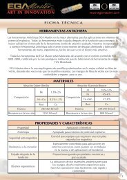
DIGITAL MULTIMETERDESCRIPTION1. Range Control Button2. Data Hold Button3. AC/DC Current or SelectingButton4. Socket for transistor test5. Function switch/Power switch6. V/Ω/F Input Jack7. COM Input Jack8. mA/Cx Input Jack9. 10A Input Jack1. Range control buttonRange for AC/DC voltage, AC/DC current (µA and mA only), resistance and frequencymeasuring can be selected manually or handled by autoranging. Push this button as following tochoose range control mode and desired ranges.
2. Data hold buttonWhen this button is pushed, the display will show the last reading and “D-H” symbol will appearuntil pushing it again.Data holding will be cancelled automatically when the function switch is rotated.3. AC/DC current or Selecting buttonPush this button to select AC or DC current measuring function when the function switch is setat µA, mA, A positions.Push this button to selectposition.measuring function when the function switch is set at4. Input jacksThis device has four input jacks that are protected against limits overload. During use, connectthe black test lead to the COM jack and the red test lead as shown below:Function Red lead connection Input limitsDCV/ACV V / Ω / F 1000V DC or 750V rms ACkHz V / Ω / F 250V DC or rms ACΩ/ V / Ω / F 250V DC or rms ACµA / mA mA / Cx 300mA DC or rms ACnF / µF mA / Cx 300mA fuse protectedA 10A 10A DC or rms ACµA / mA ranges are protected by fuses.
SPECIFICATIONS1. GeneralDisplay:Max. VoltageBetween Terminalsand Herat GroundFuse ProtectionMeasurementMethodRanging MethodOverrange IndicationPolarity IndicationPower supply:Operatingconditions:Dimension:Weight:LCD, 3260 counts max.1000V DC o 750V rms ACµA, mA: F 300 mA / 250VDual slope integration A/D converterAuto/Manual“OL” display“-“ display9V battery, NEDA 1604 o 6F22Operating: 0 to 40 ºC (32ºF to 104ºF)TemperatureStorage: -10ºC to 50ºC (10ºF to 122ºF)Humidity < 80%91 x 189 x 31.5 mm310 gr.2. DC VoltageRange Resolution Accuracy326mV 0.1mV ± 0.5% of rdg ± 2 digits3.26V 1mV ± 0.8% of rdg ± 2 digits32.6V 10mV ± 0.8% of rdg ± 2 digits326V 0.1V ± 0.8% of rdg ± 2 digits1000V 1V ± 0.8% of rdg ± 2 digitsInput impedance: 10MΩ, more than 100MΩ at 326mV range.
3. AC VoltageRange Resolution Accuracy3.26V 1mV ± 1.2% of rdg ± 3 digits32.6V 10mV ± 0.8% of rdg ± 3 digits326V 0.1V ± 1.2% of rdg ± 3 digits1000V 1V ± 1.2% of rdg ± 3 digitsInput impedance: 10MΩ.Frequency range: 40 to 400Hz, 40 to 200Hz for 3.26V range.Response: average, calibrated in rms of sine wave.4. DC CurrentRange Resolution Accuracy Burden Voltage326µA 0.1µA ± 1.2% of rdg ± 3 digits 0.5mV / µA3260µA 1µA ± 1.2% of rdg ± 3 digits 0.5mV / µA32.6mA 10µA ± 1.2% of rdg ± 3 digits 8.0mV / mA326mA 0.1mA ± 1.2% of rdg ± 3 digits 8.0mV / mA10A 10mA ± 4.0% of rdg ± 3 digits 0.02V / AOverload Protection: F 300mA fuse for µA and mA ranges.5. AC CurrentRange Resolution Accuracy Burden Voltage326µA 0.1µA ± 1.5% of rdg ± 5 digits 0.5mV / µA3260µA 1µA ± 1.8% of rdg ± 5 digits 0.5mV / µA32.6mA 10µA ± 1.8% of rdg ± 5 digits 8.0mV / mA326mA 0.1mA ± 2.0% of rdg ± 5 digits 8.0mV / mA10A 10mA ± 5.0% of rdg ± 7 digits 0.02V / AOverload protection: F 300mA fuse for µA and mA ranges.Frequency range: 40 to 400 HzResponse: average, calibrated in rms of sine wave.
6. ResistanceRange Resolution Accuracy326Ω 0.1Ω ± 1.0% of rdg ± 3 digits3.26kΩ 1Ω ± 1.0% of rdg ± 1 digits32.6 kΩ 10Ω ± 1.0% of rdg ± 1 digits326 kΩ 100Ω ± 1.0% of rdg ± 1 digits3.26MΩ 1kΩ ± 1.0% of rdg ± 1 digits32.6MΩ 10kΩ ± 2.0% of rdg ± 2 digitsMaximun open circuit voltage: 1.3V7. CapacitanceRange Resolution Accuracy326nF 0.1nF ± 5.0% of rdg ± 10 digits32.6µF 10nF ± 5.0% of rdg ± 10 digits8. FrequencyRange Resolution Accuracy32.6kHz 10Hz ± 1.5% of rdg ± 10 digits150kHz 100Hz ± 3.0% of rdg ± 10 digitsSensitivity: 500mV rms up to 50kHz, 1V rms for 50kHz to 150kHz.BATTERY AND FUSE REPLACEMENTIf the sign appears on the LCD display, it indicates that the battery should be replaced.Remove screws on the back cover and open the case. Replace the exhausted battery with anew one.Fuse rarely need replacement, and when blows, it is almost always as a result of the operator’serror. Open the case as mentioned above and take the PCB assembly out form the case.Replace the blown fuse rating specified.Warning: Before attempting to open the case, be sure that test leads have been disconnectedfrom measurement circuit to avoid electric shock hazard.For protection against fire, replace fuses only with specified ratings: F1: F 300mA/250V.
OPERATING INSTRUCTION1. Measuring voltage• Connect the black test lead to the COM jack and the red test lead to the V / Ω / F jack.• Set the function switch at V V ~ range to be used and connect test leads across thesource or load under measurement.• Read LCD display. The polarity of red connection will be indicated when making a DCmeasurement.2. Measuring current• Connect the black test lead to the COM jack and the red test lead to the mA/Cx jack fora maximum of 300mA. For a maximum of 10A, move the red lead to the A jack.• Set the function switch at µA, mA or A range to be used and push / ~ button to selectDCA or ACA measuring mode.• Connect test leads in series with the load in which the current is to be measured.• Read LCD display. The polarity of red lead connection will be indicated when making aDC measurement.3. Measuring resistance• Connect the black test lead to the COM jack and the red test lead to the V / Ω / F jack(NOTE: The polarity of the red lead connection is positive “+”)• Set the function switch at Ω range to be used and connect test leads across theresistance under measurement.NOTE:• For resistance above 3.26MΩ, the device may take a few seconds to stabilize reading.This is normal for high resistance measuring.• When the input is not connected, i.e. al open circuit, the figure “OL” will be displayed forthe over-range condition• When checking in-circuit resistance, be sure the circuit under test has all powerremoved and all capacitors are fully discharged.
4. Measuring capacitance• Connect the black test lead to the COM jack and the red test lead to the mA/Cx jack.(NOTE: The polarity of the lead connection is positive “+”)• Set the function switch al nF or µF position to be used.• Connect test leads across the capacitor under measurement and be sure that thepolarity of connection is observed.NOTE:• When checking in-circuit capacitance, be sure that the circuit has all power removedand all capacitor are fully discharged.• The range control mode in capacitance measurement is manual ranging and only tworanges (326nF, 32.6µF) are provided.• If the range control button is used in this function measuring, decimal points may be atincorrect positions.• At the nF range, when the capacitor to be measured is not connected to test leads, theLCD may not read zero, but a few counts. These counts have to be subtracted frommeasuring results.5. Measuring frequency• Connect the black test lead to the COM jack and the red test lead to the V / Ω / F jack.• Set the function switch at the kHz position and connect test leads across the source orload under measurement.NOTE:• The input voltage should be between 200mV and 10V rms AC. If the voltage is morethan 10V rms, reading may be out of the accuracy range.6. Continuity & Diode test• Connect the black test lead to the COM jack and the red test lead to the V / Ω / F jack(NOTE: The polarity of the red lead connection is positive “+”)• Set the function switch at position and push the button to select continuityor diode test mode.• In continuity testing, if continuity exists (i.e., resistance less than about 50 Ω), built-inbuzzer will sound.• If diode test mode is selected, connect the red and black leads to the anode andcathode of diode under test. The forward voltage drop of this diode in V will bedisplayed.
7. Transistor test• Set the function switch al hFE position.• Identity whether the transistor is NPN or PNP type and locate emitter, base andcollector lead. Insert leads of the transistor to be tested into proper holes of the testingsockets on the front panel.• LCD display will show the approximate hFE value at the test condition of base current10µA and Vce 3.2V.PRELIMINARY• When using the multimeter, the user must observe all normal safety rules concerning:o Protection against the dangers of electrical current.o Protection of the meter against misuse.• Full compliance with safety standards can be guaranteed only if used with test leadssupplied. If necessary, they must be replaced with the same model or same electric ratings.Measuring leads must be in good condition.DURING USE• Never exceed the protection limit values indicated in specifications for each ofmeasurement.• When the device is linked to a measurement circuit, do not touch unused terminals.• When the value scale to be measured is unknown beforehand, set the range selector atthe highest position.• Before rotating the range selector to change functions, disconnect test leads from thecircuit under test.• When carrying out measurements on TV or switching power circuits, always remember thatthere may be high amplitude voltages pulses at test points which can damage the meter.• Never perform resistance measurements on live circuits.• Never perform capacitance measurements unless the capacitor to be measured has beendischarged fully.• Always be careful when working with voltages above 60V DC or 30V AC rms. Keep fingersbehind the probe barriers while measuring.
MAINTENANCEBefore opening the device, always disconnect test leads from all sources of electric current.For continue protection against fire, replace fuse only with specified voltage and current ratings: F1:F 300mA/250V.If any faults or abnormalities are observed, the multimeter can not the be used any more and it hasto be checked out.Never use the meter unless the back cover is in place and fastened fully.To clean the meter, use a damp cloth and mild detergent only, do not use abrasives or solvents onit.
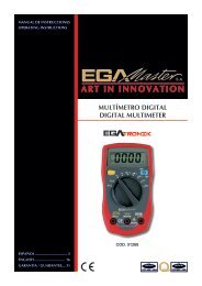
MULTÍMETRO DIGITALPARTES DEL MULTÍMETRO1. Botón para el control del rango2. Botón “Data Hold””3. Indicador de señal4. Botón de selección AC/DC5. Interruptor de funciones6. Entrada V/Ω/F7. Entrada COM8. Entrada mA/Cx9. Entrada 10A1. Botón de control de rangoEl rango para la medida del voltaje AC/DC, corriente AC/DC (solo µA y mA), resistencia yfrecuencia debe ser seleccionado manualmente. Pulsar el botón, eligiendo el rango deseado.
2. Botón Data holdCuando el botón está pulsado, la pantalla visualizará el último valor leído y el símbolo “D-H”deberá aparecer hasta que lo pulses otra vez.La función data hold se cancelará automáticamente cuando se rote el interruptor de funciones.3. Botón de selección o corriente AC/DCPulsar dicho botón para seleccionar corriente AC o DC cuando el interruptor está cambiado alas posiciones µA, mA, A.Pulsar dicho botón para seleccionar la función de medidacuando el interruptor estécambiado a la posición .4. EntradasEste multímetro posee cuatro entradas que están protegidas contra la sobrecarga de los límitesestablecidos. Durante su uso, conectar el cable negro a la entrada COM y el rojo según lovisualizado a continuación:Función Conexión del cable rojo Límites de entradaDCV/ACV V / Ω / F 1000V DC o 750V rms ACkHz V / Ω / F 250V DC o rms ACΩ/ V / Ω / F 250V DC o rms ACµA / mA mA / Cx 300mA DC o rms ACnF / µF mA / Cx 300mA fusible protegidoA 10A 10A DC o rms ACLos rangos µA/mA están protegidos por fusibles.
3. Voltaje ACRango Resolución Precisión3.26V 1mV ± 1.2% (rdg ± 3 dígitos)32.6V 10mV ± 0.8% (rdg ± 3 dígitos)326V 0.1V ± 1.2% (rdg ± 3 dígitos)1000V 1V ± 1.2% (rdg ± 3 dígitos)Impedancia de entrada: 10MΩ.Rango de frecuencia: 40 de 400Hz, 40 de 200Hz a 3.26V de rango.Respuesta: promedio, calibrado en rms4. Corriente DCRango Resolución Precisión Voltaje de carga326µA 0.1µA ± 1.2% (rdg ± 3 digitos) 0.5mV / µA3260µA 1µA ± 1.2% (rdg ± 3 digitos) 0.5mV / µA32.6mA 10µA ± 1.2% (rdg ± 3 digitos) 8.0mV / mA326mA 0.1mA ± 1.2% (rdg ± 3 digitos) 8.0mV / mA10A 10mA ± 4.0% (rdg ± 3 digitos) 0.02V / AProtección de sobrecarga: fusible F 300mA para los rangos µA y mA.5. Corriente ACRango Resolución Precisión Voltaje de carga326µA 0.1µA ± 1.5% (rdg ± 5 digitos) 0.5mV / µA3260µA 1µA ± 1.8% (rdg ± 5 dígitos) 0.5mV / µA32.6mA 10µA ± 1.8% (rdg ± 5 dígitos) 8.0mV / mA326mA 0.1mA ± 2.0% (rdg ± 5 dígitos) 8.0mV / mA10A 10mA ± 5.0% (rdg ± 7 dígitos) 0.02V / AProtección de sobrecarga: fusible F 300mA para los rangos µA y mA.Rango de frecuencia: 40 a 400 HzRespuesta: promedio, calibrado en rms en ondas senoidales.
6. ResistenciaRango Resolución Precisión326Ω 0.1Ω ± 1.0% (rdg ± 3 dígitos)3.26kΩ 1Ω ± 1.0% (rdg ± 1 dígitos)32.6 kΩ 10Ω ± 1.0% (rdg ± 1 dígitos)326 kΩ 100Ω ± 1.0% (rdg ± 1 dígitos)3.26MΩ 1kΩ ± 1.0% (rdg ± 1 dígitos)32.6MΩ 10kΩ ± 2.0% (rdg ± 2 dígitos)Máximo voltaje del circuito abierto: 1.3V7. CondensadoresRango Resolución Precisión326nF 0.1nF ± 5.0% (rdg ± 10 dígitos)32.6µF 10nF ± 5.0% (rdg ± 10 dígitos)8. FrecuenciaRango Resolución Precisión32.6kHz 10Hz ± 1.5% (rdg ± 10 dígitos)150kHz 100Hz ± 3.0% (rdg ± 10 dígitos)Sensibilidad: 500mV rms hasta 50kHz, 1V rms para 50kHz a 150kHz.BATERÍA Y CAMBIO DE FUSIBLESi el símbolo aparece en la pantalla LCD, esto indica que la batería deberáreemplazarse. Quitar los tornillos de la tapa de la batería y abrirla. Reemplazar la batería porotra nueva.El fusible raramente necesita ser reemplazado y casi siempre suele ser un error del multimetro.Abrir la tapa y coger el PCB. Reemplazar el fusible fundido según el rango especificado.Atención: Antes de abrir la tapa, estar seguros de que el cable esté desconectado del circuitode medida para evitar problemas eléctricos.Para protecciones contra el fuego, reemplazar los fusibles solo con los rangos especificados:F1: F 300mA/250V.
8. Medida de la capacidad de los condensadores• Conectar el cable negro a la entrada COM y el rojo a la entrada mA/Cx. (NOTA: Lapolaridad de la conexión es positiva “+”)• Elegir la función de la posición nF o µF.• Conectar los cables alrededor del condensador y estar seguro de que la polaridad de laconexión se visualiza.NOTA:• Cuando se chequea la capacidad de los condensadores del circuito, estar seguros deque todos los componentes del circuito están quitados y todos los condensadoresdescargados.• El modo de control de rango en medida de condensadores es manual y solo estáprovisto de dos rangos (326nF, 32.6µF).• Si el botón de control de rangos está siendo utilizado en esta función de medida, lospuntos decimales estarán en posición incorrecta.• En el rango nF, cuando el condensador a medir no está conectado a los cables, lapantalla no debe mostrar cero. Dicho dato tiene que ser restado de los resultadosmedidos.9. Medida de frecuencia• Conectar el cable negro a la entrada COM y el cable rojo a la entrada V / Ω / F.• Elegir la function kHz y conectar los cables alrededor de la carga.NOTA:• El voltaje de entrada debería estar entre 200mV y 10V rms AC. Si el voltaje está másde 10V rms, la lectura estará fuera de sus límites.10. Continuidad y test de diodo• Conectar el cable negro a la entrada COM y el cable rojo a la entrada V / Ω / F (NOTA:La polaridad de la conexión es positiva “+”)• Elegir la función y pulsar el botón para seleccionar la continuidad o elmodo test de diodo.• Para comprobar la continuidad, si la continuidad existe (p.e., resistencia menor a 50 Ω),el timbre deberá sonar.• Si el modo de test de diodo está seleccionado, conectar el cable rojo y el negro alcátodo y ánodo del diodo. El voltaje irá disminuyendo, y deberá visualizarse enpantalla.
11. Test de transistor• Elegir la función hFE.• Aunque el transistor sea de tipo NPN o PNP, localizar el emisor, base y colector.Insertar los cables del transistor para chequear los agujeros adecuados del frontal delpanel.• La pantalla LCD deberá visualizar el valor aproximado en hFE de la corriente base10µA y Vce 3.2V.PRELIMINAR• Cuando se usa el multímetro, el usuario tiene que seguir las siguientes normas deseguridad:o Protección contra daños de corriente eléctrica.o Protección del multímetro contra usos incorrectos.• Los estándares de seguridad deben estar garantizados solo si se usan los cables cagados.Si es necesario, tienen que reemplazarse por otro del mismo modelo. Los cables debenestar en buenas condiciones.DURANTE EL USO• Nunca exceder los valores límites de protección indicados en las especificaciones paracada medida.• Cuando el multímetro está unido al circuito, no tocar los terminales.• Cuando el valor de escala a medir es desconocido, posicionar el selector de rangos en laposición más alta.• Antes cambiar el selector de rangos, desconectar los cables del circuito.• Recordar siempre que amplios voltajes de corriente pueden dañar el multímetro.• Nunca medir resistencias en circuitos en tensión.• Nunca realizar medidas de condensadores a menos que el condensador esté descargado.• Trabajar siempre con cuidado cuando se trabaja con voltajes alrededor de 60V DC o 30VAC rms. Colocar los dedos por debajo de la sonda protectora mientras se mide.
MANTENIMIENTOAntes de abrir el multímetro, siempre desconectar los cables de todas las cargas eléctricas.Para continuar la protección contra el fuego, reemplazar el fusible solo con los rangos de corrientey voltaje especificados: F1: F 300mA/250V.Si se observa algún defecto o algo anormal, el multímetro puede que no se deba usar más, y porello hay que verificarlo.Nunca usar el multímetro a menos que la tapa de la batería esté en su sitio y fijada correctamente.Para limpiar el multímetro, usar una trapo húmedo y un jabón suave, no usar abrasivos odisolventes sobre el.