Installation and Commissioning
Installation and Commissioning Installation and Commissioning
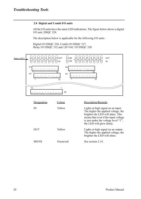
Troubleshooting Tools2.8 Digital and Combi I/O unitsAll the I/O units have the same LED indications. The figure below shows a digitalI/O unit, DSQC 328.The description below is applicable for the following I/O units:Digital I/O DSQC 328, Combi I/O DSQC 327,Relay I/O DSQC 332 and 120 VAC I/O DSQC 320.Status LED’s12345678OUTINMSNS910111213141516OUTINX1X3X21 101X410110110121X5Designation Colour Description/RemedyIN Yellow Lights at high signal on an input.The higher the applied voltage, thebrighter the LED will shine. Thismeans that even if the input voltageis just under the voltage level “1”,the LED will glow dimly.OUT Yellow Lights at high signal on an output.The higher the applied voltage, thebrighter the LED will shine.MS/NS Green/red See section 2.14.20 Product Manual
Troubleshooting Tools2.9 Analog I/O, DSQC 355Bus status LED’sBus staus LED’sAnalog I/ODSQC 355X8 X7S2 S3X2X5 X3ABB flexible AutomationN.URS232 RxCAN Rx+5V+12VMSN.URS232 TxCAN Tx-12VNSDesignation Colour Description/RemedyNS/MS Green/red See section 2.14.RS232 Rx Green Indicates the state of the RS232 Rx line.LED is active when receiving data.If no light, check communication line and connections.RS232 Tx Green Indicates the state of the RS232 Tx line.LED is active when tranceiving data.If no light when transmission is expected, checkerror messages and check also system boards inrack.+5VDC / +12VDC /-12VDC Green Indicates that supply voltage is present and atcorrect level.Check that voltage is present on power unit.Check that power is present in power connector.If not, check cables and connectors.If power is applied to unit but unit does notwork, replace the unit.Product Manual 21
- Page 269 and 270: Installation and CommissioningInsta
- Page 271 and 272: Installation and CommissioningInsta
- Page 273 and 274: Installation and CommissioningExter
- Page 275 and 276: Installation and CommissioningExter
- Page 277 and 278: Installation and CommissioningExter
- Page 279 and 280: Installation and CommissioningExter
- Page 281 and 282: Installation and CommissioningExter
- Page 283 and 284: Installation and CommissioningExter
- Page 285 and 286: Installation and CommissioningExter
- Page 287 and 288: Installation and CommissioningExter
- Page 289 and 290: Installation and CommissioningExter
- Page 291 and 292: Installation and CommissioningExter
- Page 293 and 294: MaintenanceCONTENTSPage1 Maintenanc
- Page 295 and 296: MaintenanceMaintenanceThe robot is
- Page 297 and 298: Maintenance2.3 Lubricating spring b
- Page 299 and 300: Maintenance2.7 Changing the battery
- Page 301 and 302: Troubleshooting ToolsCONTENTSPage1
- Page 303 and 304: Troubleshooting ToolsTroubleshootin
- Page 305 and 306: Troubleshooting Tools1.1 TestsMost
- Page 307 and 308: Troubleshooting Tools1.2.1 Entering
- Page 309 and 310: Troubleshooting Tools5. MC/ERWM RWM
- Page 311 and 312: Troubleshooting Tools5. Miscellaneo
- Page 313 and 314: Troubleshooting Tools9. Specific te
- Page 315 and 316: Troubleshooting Tools2.3 Main compu
- Page 317 and 318: Troubleshooting Tools2.6 Power supp
- Page 319: Troubleshooting Tools2.7 Panel unit
- Page 323 and 324: Troubleshooting Tools2.11 Interbus-
- Page 325 and 326: Troubleshooting Tools2.13 Encoder i
- Page 327 and 328: Troubleshooting Tools2.14 Status LE
- Page 329 and 330: Troubleshooting ToolsModule- and ne
- Page 331 and 332: Troubleshooting Tools3.2 Signal des
- Page 333 and 334: Troubleshooting Tools3.3 X1 and X2
- Page 335 and 336: Troubleshooting Tools3.4.2 X9 VBATT
- Page 337 and 338: Troubleshooting Tools3.4.5 Disk dri
- Page 339 and 340: Troubleshooting Tools3.4.7 CANX9Pin
- Page 341 and 342: Fault tracing guideCONTENTSPage1 Fa
- Page 343 and 344: Fault tracing guide1 Fault tracing
- Page 345 and 346: Fault tracing guide1.4 Robot comput
- Page 347 and 348: Fault tracing guideInputs DINameAS1
- Page 349 and 350: Fault tracing guide1.7 Serial Commu
- Page 351 and 352: Fault tracing guide1.11 Disk DriveT
- Page 353 and 354: ABB Flexible Automation ABThis chap
- Page 355 and 356: RepairsCONTENTSPage7.3 Changing the
- Page 357 and 358: General DescriptionRepairsAxis 1 ro
- Page 359 and 360: General DescriptionRepairs1.2 Cauti
- Page 361 and 362: General DescriptionRepairs12. The s
- Page 363 and 364: General DescriptionRepairs1.5 Tight
- Page 365 and 366: Axis 1Repairs2.2 Changing the gearb
- Page 367 and 368: Axis 1Repairs2.4 Replacing the mech
- Page 369 and 370: Axis 2 Repairs3.2 Changing the gear
Troubleshooting Tools2.8 Digital <strong>and</strong> Combi I/O unitsAll the I/O units have the same LED indications. The figure below shows a digitalI/O unit, DSQC 328.The description below is applicable for the following I/O units:Digital I/O DSQC 328, Combi I/O DSQC 327,Relay I/O DSQC 332 <strong>and</strong> 120 VAC I/O DSQC 320.Status LED’s12345678OUTINMSNS910111213141516OUTINX1X3X21 101X410110110121X5Designation Colour Description/RemedyIN Yellow Lights at high signal on an input.The higher the applied voltage, thebrighter the LED will shine. Thismeans that even if the input voltageis just under the voltage level “1”,the LED will glow dimly.OUT Yellow Lights at high signal on an output.The higher the applied voltage, thebrighter the LED will shine.MS/NS Green/red See section 2.14.20 Product Manual


