Installation and Commissioning
Installation and Commissioning Installation and Commissioning
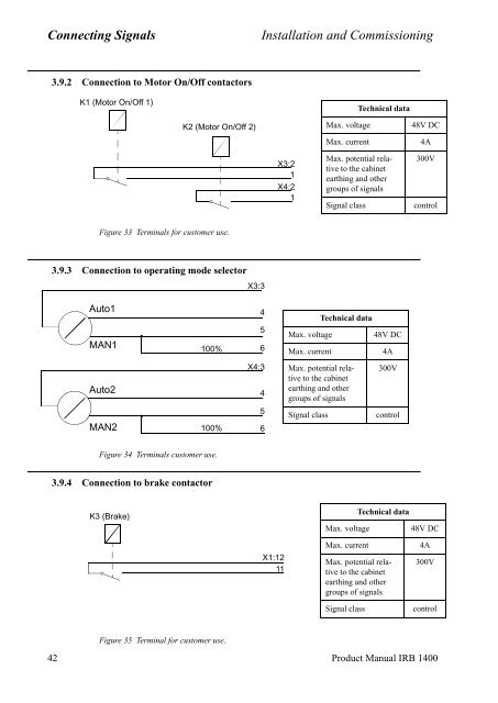
Connecting SignalsInstallation and Commissioning3.9.2 Connection to Motor On/Off contactorsK1 (Motor On/Off 1)Technical dataK2 (Motor On/Off 2)Max. voltageMax. current48V DC4AX3:21X4:21Max. potential relativeto the cabinetearthing and othergroups of signalsSignal class300VcontrolFigure 33 Terminals for customer use.3.9.3 Connection to operating mode selectorX3:3Auto1MAN1100%456Max. voltageMax. currentTechnical data48V DC4AAuto2MAN2100%X4:3456Max. potential relativeto the cabinetearthing and othergroups of signalsSignal class300VcontrolFigure 34 Terminals customer use.3.9.4 Connection to brake contactorK3 (Brake)Max. voltageTechnical data48V DCX1:1211Max. currentMax. potential relativeto the cabinetearthing and othergroups of signalsSignal class4A300VcontrolFigure 35 Terminal for customer use.42 Product Manual IRB 1400
Installation and CommissioningConnecting Signals3.10 External customer connectionsCustomer contacts, on panel unit: X1- X4.WARNING!REMOVE JUMPERS BEFORE CONNECTINGANY EXTERNAL EQUIPMENTENMSNSES1ES2 GS1 GS2 AS1 AS2Chain statusLED´sX11 2 3 4 5 6 7 8 9 10 11 121 2 3 4 5 6 7 8 9 10 11 12X3X21 2 3 4 5 6 7 8 9 10 11 12 1 2 3 4 5 6 7 8 9 10 11 12X4= jumperCustomer connections: X1 - X4, located on the panel unit.The signal names refer to the circuit diagram in chapter 11.X1Signal name Pin CommentES1 out:B 1 Emergency stop out chain 1ES1 out:A 2 Emergency stop out chain 1Ext. LIM1:B 3 External limit switch chain 1Ext. LIM1:A 4 External limit switch chain 10V 5 0V external contactor 1CONT1 6 External contactor 1Int. 0V ES1 7 Internal supply 0V of emergency stop chain 1Ext. 0V ES1 8 External supply 0V of emergency stop chain 1Ext. ES1 IN 9 External emergency stop in chain 1Ext. ES1 OUT 10 External emergency stop out chain 1Ext. BRAKE B 11 Contactor for external brakeExt. BRAKE A 12 Contactor for external brakeProduct Manual IRB 1400 43
- Page 173 and 174: System DescriptionServo System3 Ser
- Page 175 and 176: System DescriptionI/O System4 I/O S
- Page 177 and 178: System DescriptionSafety System5 Sa
- Page 179 and 180: System DescriptionSafety System5.4
- Page 181 and 182: System DescriptionExternal Axes6 Ex
- Page 183 and 184: Installation and CommissioningCONTE
- Page 185 and 186: Installation and CommissioningCONTE
- Page 187 and 188: Installation and CommissioningTrans
- Page 189 and 190: Installation and CommissioningOn-Si
- Page 191 and 192: Installation and CommissioningOn-Si
- Page 193 and 194: Installation and CommissioningOn-Si
- Page 195 and 196: Installation and CommissioningOn-Si
- Page 197 and 198: Installation and CommissioningOn-Si
- Page 199 and 200: Installation and CommissioningOn-Si
- Page 201 and 202: Installation and CommissioningOn-Si
- Page 203 and 204: Installation and CommissioningOn-Si
- Page 205 and 206: Installation and CommissioningOn-Si
- Page 207 and 208: Installation and CommissioningOn-Si
- Page 209 and 210: Installation and CommissioningOn-Si
- Page 211 and 212: Installation and CommissioningOn-Si
- Page 213 and 214: Installation and CommissioningConne
- Page 215 and 216: Installation and CommissioningConne
- Page 217 and 218: Installation and CommissioningConne
- Page 219 and 220: Installation and CommissioningConne
- Page 221 and 222: Installation and CommissioningConne
- Page 223: Installation and CommissioningConne
- Page 227 and 228: Installation and CommissioningConne
- Page 229 and 230: Installation and CommissioningConne
- Page 231 and 232: Installation and CommissioningConne
- Page 233 and 234: Installation and CommissioningConne
- Page 235 and 236: Installation and CommissioningConne
- Page 237 and 238: Installation and CommissioningConne
- Page 239 and 240: Installation and CommissioningConne
- Page 241 and 242: Installation and CommissioningConne
- Page 243 and 244: Installation and CommissioningConne
- Page 245 and 246: Installation and CommissioningConne
- Page 247 and 248: Installation and CommissioningConne
- Page 249 and 250: Installation and CommissioningConne
- Page 251 and 252: Installation and CommissioningConne
- Page 253 and 254: Installation and CommissioningConne
- Page 255 and 256: Installation and CommissioningConne
- Page 257 and 258: Installation and CommissioningConne
- Page 259 and 260: Installation and CommissioningConne
- Page 261 and 262: Installation and CommissioningConne
- Page 263 and 264: Installation and CommissioningConne
- Page 265 and 266: Installation and CommissioningConne
- Page 267 and 268: Installation and CommissioningInsta
- Page 269 and 270: Installation and CommissioningInsta
- Page 271 and 272: Installation and CommissioningInsta
- Page 273 and 274: Installation and CommissioningExter
Connecting Signals<strong>Installation</strong> <strong>and</strong> <strong>Commissioning</strong>3.9.2 Connection to Motor On/Off contactorsK1 (Motor On/Off 1)Technical dataK2 (Motor On/Off 2)Max. voltageMax. current48V DC4AX3:21X4:21Max. potential relativeto the cabinetearthing <strong>and</strong> othergroups of signalsSignal class300VcontrolFigure 33 Terminals for customer use.3.9.3 Connection to operating mode selectorX3:3Auto1MAN1100%456Max. voltageMax. currentTechnical data48V DC4AAuto2MAN2100%X4:3456Max. potential relativeto the cabinetearthing <strong>and</strong> othergroups of signalsSignal class300VcontrolFigure 34 Terminals customer use.3.9.4 Connection to brake contactorK3 (Brake)Max. voltageTechnical data48V DCX1:1211Max. currentMax. potential relativeto the cabinetearthing <strong>and</strong> othergroups of signalsSignal class4A300VcontrolFigure 35 Terminal for customer use.42 Product Manual IRB 1400


