- Page 1 and 2:
3HAC 2914-1M98Product On-line Manua
- Page 3 and 4:
ABB Flexible Automation ABProduct M
- Page 5 and 6:
IntroductionCONTENTSPage1 How to us
- Page 7 and 8:
IntroductionIntroduction1 How to us
- Page 9 and 10:
Introduction.ABB Robotics Products
- Page 11 and 12:
Product Specification IRB 1400CONTE
- Page 13 and 14:
Introduction1 IntroductionThank you
- Page 15 and 16:
Description2 Description2.1 Structu
- Page 17 and 18:
DescriptionRestricting the working
- Page 19 and 20:
DescriptionUsing a key switch, the
- Page 21 and 22:
DescriptionEditing programsPrograms
- Page 23 and 24:
DescriptionThe robot has several fu
- Page 25 and 26:
DescriptionMotion performanceThe Qu
- Page 27 and 28:
Description2.9 External AxesThe rob
- Page 29 and 30:
Technical specification3 Technical
- Page 31 and 32:
Technical specification150667398475
- Page 33 and 34:
Technical specification3.3 Operatio
- Page 35 and 36:
Technical specificationProgram star
- Page 37 and 38:
Technical specificationMounting of
- Page 39 and 40:
Technical specificationWHILE Repeat
- Page 41 and 42:
Technical specificationATan/ATan2Co
- Page 43 and 44:
Technical specification3.8 Robot Mo
- Page 45 and 46:
Technical specificationPerformance
- Page 47 and 48:
Technical specification3.10 Inputs
- Page 49 and 50:
Technical specificationDigital outp
- Page 51 and 52:
Technical specification3.11 Communi
- Page 53 and 54:
Specification of Variants and Optio
- Page 55 and 56:
Specification of Variants and Optio
- Page 57 and 58:
Specification of Variants and Optio
- Page 59 and 60:
Specification of Variants and Optio
- Page 61 and 62:
Specification of Variants and Optio
- Page 63 and 64:
Specification of Variants and Optio
- Page 65 and 66:
Accessories5 AccessoriesThere is a
- Page 67 and 68:
Product Specification RobotWareCONT
- Page 69 and 70:
Introduction1 IntroductionRobotWare
- Page 71 and 72:
Rapid Language and Environment2 Bas
- Page 73 and 74:
Motion Control2.3 Motion ControlTru
- Page 75 and 76:
Safety2.4 SafetyMany safety concept
- Page 77 and 78:
Advanced Functions 3.13 BaseWare Op
- Page 79 and 80:
Advanced Functions 3.1World ZonesA
- Page 81 and 82:
Advanced Functions 3.1RAPID instruc
- Page 83 and 84:
Advanced Motion 3.1Contour tracking
- Page 85 and 86:
Multitasking 3.13.3 Multitasking 3.
- Page 87 and 88:
FactoryWare Interface 3.1Examples o
- Page 89 and 90:
Ethernet Services 3.13.6 Ethernet S
- Page 91 and 92:
ScreenViewer 3.13.8 ScreenViewer 3.
- Page 93 and 94:
Conveyor Tracking 3.13.9 Conveyor T
- Page 95 and 96:
ArcWare 3.14 ProcessWare4.1 ArcWare
- Page 97 and 98:
ArcWare 3.1Analog inputs (cont.)Vol
- Page 99 and 100:
SpotWare 3.14.3 SpotWare 3.1SpotWar
- Page 101 and 102:
SpotWare 3.1manual close gunmanual
- Page 103 and 104:
SpotWare Plus 3.14.4 SpotWare Plus
- Page 105 and 106:
GlueWare 3.1Interface signalsWhen i
- Page 107 and 108:
PaintWare 3.1RAPID instructions inc
- Page 109 and 110:
ProductsAny number of different pro
- Page 111 and 112:
Available memory5 Memory and Docume
- Page 113 and 114:
DeskWare Office 3.06 DeskWare6.1 De
- Page 115 and 116:
DeskWare Office 3.0The “User Pref
- Page 117 and 118:
Programming Station 3.0Editing of b
- Page 119 and 120:
Programming Station 3.0• Products
- Page 121 and 122:
Programming Station 3.0Output from
- Page 123 and 124:
Training Center 3.0PC System Requir
- Page 125 and 126: Library 3.0ServiceLog allows the us
- Page 127 and 128: Robot Lab 3.0Cycle TimeClock contro
- Page 129 and 130: RobComm 3.07 FactoryWare7.1 RobComm
- Page 131 and 132: RobComm 3.0Following is a brief des
- Page 133 and 134: RobView 3.17.2 RobView 3.1RobView i
- Page 135 and 136: RobView 3.1File managerWhen the use
- Page 137 and 138: RobView 3.1In addition, also a butt
- Page 139 and 140: RobView 3.1Technical specificationP
- Page 141 and 142: DDE Server 2.3SCWriteThe user can a
- Page 143 and 144: DDE Server 2.3DDE Server for multip
- Page 145 and 146: SafetyCONTENTSPage1 General........
- Page 147 and 148: SafetySafety1 GeneralThis informati
- Page 149 and 150: Safety5 Safe Working ProceduresSafe
- Page 151 and 152: Safety7.2 Emergency stopsAn emergen
- Page 153 and 154: SafetyWhen the Hold-to-run control
- Page 155 and 156: Safety8.2 Tools/workpiecesIt must b
- Page 157 and 158: Safety- The external voltage connec
- Page 159 and 160: To the User“Declaration by the ma
- Page 161 and 162: System DescriptionCONTENTSPage1 Str
- Page 163 and 164: System DescriptionStructure1 Struct
- Page 165 and 166: System DescriptionStructureAxis 3Up
- Page 167 and 168: System DescriptionStructure1.2 Cont
- Page 169 and 170: System DescriptionStructureLithium
- Page 171 and 172: System DescriptionComputer System2
- Page 173 and 174: System DescriptionServo System3 Ser
- Page 175: System DescriptionI/O System4 I/O S
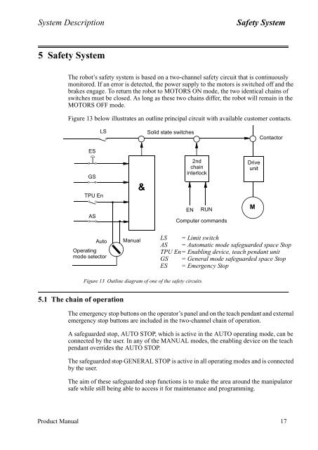
- Page 179 and 180: System DescriptionSafety System5.4
- Page 181 and 182: System DescriptionExternal Axes6 Ex
- Page 183 and 184: Installation and CommissioningCONTE
- Page 185 and 186: Installation and CommissioningCONTE
- Page 187 and 188: Installation and CommissioningTrans
- Page 189 and 190: Installation and CommissioningOn-Si
- Page 191 and 192: Installation and CommissioningOn-Si
- Page 193 and 194: Installation and CommissioningOn-Si
- Page 195 and 196: Installation and CommissioningOn-Si
- Page 197 and 198: Installation and CommissioningOn-Si
- Page 199 and 200: Installation and CommissioningOn-Si
- Page 201 and 202: Installation and CommissioningOn-Si
- Page 203 and 204: Installation and CommissioningOn-Si
- Page 205 and 206: Installation and CommissioningOn-Si
- Page 207 and 208: Installation and CommissioningOn-Si
- Page 209 and 210: Installation and CommissioningOn-Si
- Page 211 and 212: Installation and CommissioningOn-Si
- Page 213 and 214: Installation and CommissioningConne
- Page 215 and 216: Installation and CommissioningConne
- Page 217 and 218: Installation and CommissioningConne
- Page 219 and 220: Installation and CommissioningConne
- Page 221 and 222: Installation and CommissioningConne
- Page 223 and 224: Installation and CommissioningConne
- Page 225 and 226: Installation and CommissioningConne
- Page 227 and 228:
Installation and CommissioningConne
- Page 229 and 230:
Installation and CommissioningConne
- Page 231 and 232:
Installation and CommissioningConne
- Page 233 and 234:
Installation and CommissioningConne
- Page 235 and 236:
Installation and CommissioningConne
- Page 237 and 238:
Installation and CommissioningConne
- Page 239 and 240:
Installation and CommissioningConne
- Page 241 and 242:
Installation and CommissioningConne
- Page 243 and 244:
Installation and CommissioningConne
- Page 245 and 246:
Installation and CommissioningConne
- Page 247 and 248:
Installation and CommissioningConne
- Page 249 and 250:
Installation and CommissioningConne
- Page 251 and 252:
Installation and CommissioningConne
- Page 253 and 254:
Installation and CommissioningConne
- Page 255 and 256:
Installation and CommissioningConne
- Page 257 and 258:
Installation and CommissioningConne
- Page 259 and 260:
Installation and CommissioningConne
- Page 261 and 262:
Installation and CommissioningConne
- Page 263 and 264:
Installation and CommissioningConne
- Page 265 and 266:
Installation and CommissioningConne
- Page 267 and 268:
Installation and CommissioningInsta
- Page 269 and 270:
Installation and CommissioningInsta
- Page 271 and 272:
Installation and CommissioningInsta
- Page 273 and 274:
Installation and CommissioningExter
- Page 275 and 276:
Installation and CommissioningExter
- Page 277 and 278:
Installation and CommissioningExter
- Page 279 and 280:
Installation and CommissioningExter
- Page 281 and 282:
Installation and CommissioningExter
- Page 283 and 284:
Installation and CommissioningExter
- Page 285 and 286:
Installation and CommissioningExter
- Page 287 and 288:
Installation and CommissioningExter
- Page 289 and 290:
Installation and CommissioningExter
- Page 291 and 292:
Installation and CommissioningExter
- Page 293 and 294:
MaintenanceCONTENTSPage1 Maintenanc
- Page 295 and 296:
MaintenanceMaintenanceThe robot is
- Page 297 and 298:
Maintenance2.3 Lubricating spring b
- Page 299 and 300:
Maintenance2.7 Changing the battery
- Page 301 and 302:
Troubleshooting ToolsCONTENTSPage1
- Page 303 and 304:
Troubleshooting ToolsTroubleshootin
- Page 305 and 306:
Troubleshooting Tools1.1 TestsMost
- Page 307 and 308:
Troubleshooting Tools1.2.1 Entering
- Page 309 and 310:
Troubleshooting Tools5. MC/ERWM RWM
- Page 311 and 312:
Troubleshooting Tools5. Miscellaneo
- Page 313 and 314:
Troubleshooting Tools9. Specific te
- Page 315 and 316:
Troubleshooting Tools2.3 Main compu
- Page 317 and 318:
Troubleshooting Tools2.6 Power supp
- Page 319 and 320:
Troubleshooting Tools2.7 Panel unit
- Page 321 and 322:
Troubleshooting Tools2.9 Analog I/O
- Page 323 and 324:
Troubleshooting Tools2.11 Interbus-
- Page 325 and 326:
Troubleshooting Tools2.13 Encoder i
- Page 327 and 328:
Troubleshooting Tools2.14 Status LE
- Page 329 and 330:
Troubleshooting ToolsModule- and ne
- Page 331 and 332:
Troubleshooting Tools3.2 Signal des
- Page 333 and 334:
Troubleshooting Tools3.3 X1 and X2
- Page 335 and 336:
Troubleshooting Tools3.4.2 X9 VBATT
- Page 337 and 338:
Troubleshooting Tools3.4.5 Disk dri
- Page 339 and 340:
Troubleshooting Tools3.4.7 CANX9Pin
- Page 341 and 342:
Fault tracing guideCONTENTSPage1 Fa
- Page 343 and 344:
Fault tracing guide1 Fault tracing
- Page 345 and 346:
Fault tracing guide1.4 Robot comput
- Page 347 and 348:
Fault tracing guideInputs DINameAS1
- Page 349 and 350:
Fault tracing guide1.7 Serial Commu
- Page 351 and 352:
Fault tracing guide1.11 Disk DriveT
- Page 353 and 354:
ABB Flexible Automation ABThis chap
- Page 355 and 356:
RepairsCONTENTSPage7.3 Changing the
- Page 357 and 358:
General DescriptionRepairsAxis 1 ro
- Page 359 and 360:
General DescriptionRepairs1.2 Cauti
- Page 361 and 362:
General DescriptionRepairs12. The s
- Page 363 and 364:
General DescriptionRepairs1.5 Tight
- Page 365 and 366:
Axis 1Repairs2.2 Changing the gearb
- Page 367 and 368:
Axis 1Repairs2.4 Replacing the mech
- Page 369 and 370:
Axis 2 Repairs3.2 Changing the gear
- Page 371 and 372:
Axis 2 Repairs3.5 Dismantling the b
- Page 373 and 374:
Axis 3Repairs4.2 Changing the gearb
- Page 375 and 376:
Axis 3Repairs4.5 Dismantling the co
- Page 377 and 378:
Axis 3Repairs105 oFigure 4 Calibrai
- Page 379 and 380:
Axis 4 Repairs14. Connect the cabli
- Page 381 and 382:
Axis 4 RepairsTo assemble:Shim betw
- Page 383 and 384:
Axis 4 Repairs30 Product Manual IRB
- Page 385 and 386:
Cabling and Serial Measuring boardR
- Page 387 and 388:
The Wrist and Axes 5 and 6Repairs7.
- Page 389 and 390:
The Wrist and Axes 5 and 6RepairsAx
- Page 391 and 392:
Motor UnitsRepairs38 Product Manual
- Page 393 and 394:
CalibrationRepairs5. Press Enter .6
- Page 395 and 396:
CalibrationRepairs13. Release the b
- Page 397 and 398:
CalibrationRepairsCalibration plate
- Page 399 and 400:
CalibrationRepairs2. Select Service
- Page 401 and 402:
CalibrationRepairs.Figure 17 Calibr
- Page 403 and 404:
CalibrationRepairs1. Run the calibr
- Page 405 and 406:
CalibrationRepairs52 Product Manual