Installation and Commissioning
Installation and Commissioning
Installation and Commissioning
- No tags were found...

You also want an ePaper? Increase the reach of your titles
YUMPU automatically turns print PDFs into web optimized ePapers that Google loves.
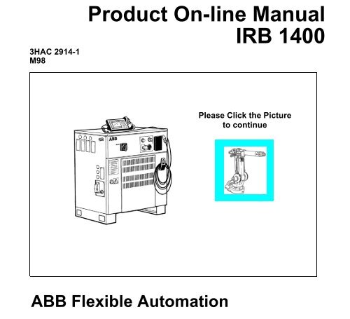
3HAC 2914-1M98Product On-line ManualIRB 1400Please Click the Pictureto continueABB Flexible Automation
The information in this document is subject to change without notice <strong>and</strong> should not be construed as acommitment by ABB Robotics Products AB. ABB Robotics Products AB assumes no responsibility forany errors that may appear in this document.In no event shall ABB Robotics Products AB be liable for incidental or consequential damages arisingfrom use of this document or of the software <strong>and</strong> hardware described in this document.This document <strong>and</strong> parts thereof must not be reproduced or copied withoutABB Robotics Products AB´s written permission, <strong>and</strong> contents thereof must not be imparted to a thirdparty nor be used for any unauthorized purpose. Contravention will be prosecuted.Additional copies of this document may be obtained from ABB Robotics Products AB at its then currentcharge.© ABB Robotics Products ABArticle number: 3HAC 2914-1Issue: M98ABB Robotics Products ABS-721 68 VästeråsSweden
ABB Flexible Automation ABProduct Manual IRB 1400 M97A, On-line ManualMAIN MENUIntroductionProduct Specification IRB 2400Product Specification RobotWareSafetyCE-declarationConfiguration ListSystem Description<strong>Installation</strong> <strong>and</strong> <strong>Commissioning</strong>MaintenanceTroubleshooting ToolsFault tracing guideCircuit DiagramRepairsSpare parts
Description20 Product Specification IRB 1400 M97A/BaseWare OS 3.0
IntroductionCONTENTSPage1 How to use this Manual........................................................................................... 32 What you must know before you use the Robot ................................................... 33 Identification ............................................................................................................ 4Product Manual 1
Introduction2 Product Manual
IntroductionIntroduction1 How to use this ManualThis manual provides information on installation, preventive maintenance, troubleshooting<strong>and</strong> how to carry out repairs on the manipulator <strong>and</strong> controller. Its intendedaudience is trained maintenance personnel with expertise in both mechanical <strong>and</strong>electrical systems. The manual does not in any way assume to take the place of themaintenance course offered by ABB Flexible Automation.Anyone reading this manual should also have access to the User’s Guide.The chapter entitled System Description provides general information on the robotstructure, such as its computer system, input <strong>and</strong> output signals, etc.How to assemble the robot <strong>and</strong> install all signals, etc., is described in the chapter on<strong>Installation</strong> <strong>and</strong> <strong>Commissioning</strong>.If an error should occur in the robot system, you can find out why it has happened inthe chapter on Troubleshooting. If you receive an error message, you can also consultthe chapter on System <strong>and</strong> Error Messages in the User’s Guide. It is very helpful tohave a copy of the circuit diagram at h<strong>and</strong> when trying to locate cabling faults.Servicing <strong>and</strong> maintenance routines are described in the chapter on Maintenance.2 What you must know before you use the Robot• Normal maintenance <strong>and</strong> repair work usually only require st<strong>and</strong>ard tools. Somerepairs, however, require specific tools. These repairs, <strong>and</strong> the type of tool required,are described in more detail in the chapter Repairs.• The power supply must always be switched off whenever work is carried out in thecontroller cabinet. Note that even though the power is switched off, the orangecolouredcables may be live. The reason for this is that these cables are connected toexternal equipment <strong>and</strong> are consequently not affected by the mains switch on thecontroller.• Circuit boards - printed boards <strong>and</strong> components - must never be h<strong>and</strong>led withoutElectro-Static-Discharge (ESD) protection in order not to damage them. Use thecarry b<strong>and</strong> located on the inside of the controller door.All personnel working with the robot system must be very familiar with the safetyregulations outlined in the chapter on Safety. Incorrect operation can damage therobot or injure someone.Product Manual 3
Introduction3 IdentificationIdentification plates indicating the type of robot <strong>and</strong> serial number, etc., are located onthe manipulator (see Figure 1) <strong>and</strong> on the front of the controller (see Figure 2).The BaseWare O.S diskettes are also marked with serial number (see Figure 3).Note! The identification plates <strong>and</strong> label shown in the figures below, only serves asexamples. For exact identification see plates on your robot in question.ABB Robotics Products ABS-721 68 Västerås Sweden Made in SwedenType:Robot version:Man. order:Nom. loadSerial. No:Date of manufacturing:Net weight2,4.120 : 1870 kg2,4-150 : 2010 kg2,8-120 : 2010 kgIRB 6400 M98IRB 6400/2.4-150XXXXXXSee instructions6400-XXXX1997-XX-XX3.0-75 : 2010 kgS/2,9-120 : 2240 kgPE/2,25-75 : 1590 kgIdentification plate showingthe IRB 6400IRB 140(0) IRB 2400 IRB 4400IRB 640 IRB 6400 IRB 840/AFigure 1 Example of identification plate <strong>and</strong> it’s location on different manipulator types.4 Product Manual
Introduction.ABB Robotics Products ABS-721 68 Västerås Sweden Made in SwedenType:Robot version:Voltage: 3 x 400 VPower:Man. order:Re.No:Serial. No:Date of manufacturing:Net weight:IRB 6400 M98IRB 6400/2.4-150Frequency: 50-60 Hz7.2 kVAXXXXXXRXXXXXXXXXX64-XXXXX1998-XX-XX240 kgFigure 2 Identification plate on the controller.64-00000System Key S4C 3.1Program No 3 HAB2390-1/03Boot disk 1 (1)Property of ABB Västerås/Sweden. All rights reserved. Reproduction,modification, use or disclosure to third parties without express authorityis strictly forbidden. Copyright 1993. Restricted to be used in thecontroller(s) with the serial no as marked on disk.ABB Robotics Products ABFigure 3 Example of a label on a BaseWare O.S diskette.Product Manual 5
Introduction6 Product Manual
Product Specification IRB 1400CONTENTSPage1 Introduction ..................................................................................................................... 32 Description....................................................................................................................... 52.1 Structure.................................................................................................................. 52.2 Safety/St<strong>and</strong>ards ..................................................................................................... 62.3 Operation ................................................................................................................ 72.4 <strong>Installation</strong> .............................................................................................................. 92.5 Programming .......................................................................................................... 92.6 Automatic Operation .............................................................................................. 122.7 Maintenance <strong>and</strong> Troubleshooting ......................................................................... 122.8 Robot Motion.......................................................................................................... 142.9 External Axes ......................................................................................................... 172.10 Inputs <strong>and</strong> Outputs................................................................................................ 172.11 Serial Communication .......................................................................................... 183 Technical specification .................................................................................................... 193.1 Structure.................................................................................................................. 193.2 Safety/St<strong>and</strong>ards ..................................................................................................... 223.3 Operation ................................................................................................................ 233.4 <strong>Installation</strong> .............................................................................................................. 243.5 Programming .......................................................................................................... 283.6 Automatic Operation .............................................................................................. 323.7 Maintenance <strong>and</strong> Troubleshooting ......................................................................... 323.8 Robot Motion.......................................................................................................... 333.9 External Axes ......................................................................................................... 363.10 Inputs <strong>and</strong> Outputs................................................................................................ 373.11 Communication..................................................................................................... 414 Specification of Variants <strong>and</strong> Options........................................................................... 435 Accessories ....................................................................................................................... 556 Index................................................................................................................................. 57Product Specification IRB 1400 M98/BaseWare OS 3.1 1
Product Specification IRB 14002 Product Specification IRB 1400 M98/BaseWare OS 3.1
Introduction1 IntroductionThank you for your interest in the IRB 1400. This manual will give you an overviewof the characteristics <strong>and</strong> performance of the robot.IRB 1400 is a 6-axis industrial robot, designed specifically for manufacturingindustries that use flexible robot-based automation. The robot has an open structurethat is specially adapted for flexible use, <strong>and</strong> can communicate extensively withexternal systems.The robot is equipped with an operating system called BaseWare OS. BaseWare OScontrols every aspect of the robot, like motion control, development <strong>and</strong> execution ofapplication programs communication etc.The functions in this document are all included in BaseWare OS, if not otherwisespecified. For additional functionality, the robot can be equipped with optionalsoftware for application support - for example gluing <strong>and</strong> arc welding, communicationfeatures - network communication - <strong>and</strong> advanced functions such as multitasking,sensor control etc. For a complete description on optional software, see the ProductSpecification RobotWare.All the features are not described in this document. For a more complete <strong>and</strong> detaileddescription, please see the User’s Guide, RAPID Reference Manual <strong>and</strong> ProductManual, or contact your nearest ABB Flexible Automation Centre.Different robot versionsThe IRB 1400, as mentioned above, is available in two different versions:- IRB 1400, for floor mounting- IRB 1400H, for inverted mounting.How to use this manualThe characteristics of the robot are described in Chapter 2: Description.The most important technical data is listed in Chapter 3: Technical specification.Note that the sections in chapter 2 <strong>and</strong> 3 are related to each other. For example, insection 2.2 you can find an overview of safety <strong>and</strong> st<strong>and</strong>ards, in section 3.2 you canfind more detailed information.To make sure that you have ordered a robot with the correct functionality, seeChapter 4: Specification of Variants <strong>and</strong> Options.In Chapter 5 you will find accessories for the robot.Chapter 6 contains an Index, to make things easier to find.Product Specification IRB 1400 M98/BaseWare OS 3.1 3
IntroductionOther manualsThe User’s Guide is a reference manual with step by step instructions on how toperform various tasks.The programming language is described in the RAPID Reference Manual.The Product Manual describes how to install the robot, as well as maintenanceprocedures <strong>and</strong> troubleshooting.The Product Specification RobotWare describes the software options.4 Product Specification IRB 1400 M98/BaseWare OS 3.1
Description2 Description2.1 StructureThe robot is made up of two main parts: a manipulator <strong>and</strong> a controller.Axis 3Axis 4 Axis 5Axis 6Axis 2Axis 1Figure 1 The IRB 1400 manipulator has 6 axes.Teach pendantOperator´s panelMains switchDisk driveFigure 2 The controller is specifically designed to control robots, which means that optimalperformance <strong>and</strong> functionality is achieved.The controller contains the electronics required to control the manipulator, externalaxes <strong>and</strong> peripheral equipment.Product Specification IRB 1400 M98/BaseWare OS 3.1 5
Description2.2 Safety/St<strong>and</strong>ardsThe robot complies fully with the health <strong>and</strong> safety st<strong>and</strong>ards specified in the EEC’sMachinery Directives as well as ANSI/RIA 15.06-1992.The robot is designed with absolute safety in mind. It has a dedicated safety systembased on a two-channel circuit which is monitored continuously. If any componentfails, the electrical power supplied to the motors shuts off <strong>and</strong> the brakes engage.Safety category 3Malfunction of a single component, such as a sticking relay, will be detected at the nextMOTOR OFF/MOTOR ON operation. MOTOR ON is then prevented <strong>and</strong> the faultysection is indicated. This complies with category 3 of EN 954-1, Safety of machinery -safety related parts of control systems - Part 1.Selecting the operating modeThe robot can be operated either manually or automatically. In manual mode, the robotcan only be operated via the teach pendant, i.e. not by any external equipment.Reduced speedIn manual mode, the speed is limited to a maximum of 250 mm/s (600 inches/min.).A speed limitation applies not only to the TCP (Tool Centre Point), but to all parts ofthe robot. It is also possible to monitor the speed of equipment mounted on the robot.Three position enabling deviceThe enabling device on the teach pendant must be used to move the robot when in manualmode. The enabling device consists of a switch with three positions, meaning thatall robot movements stop when either the enabling device is pushed fully in, or when itis released completely. This makes the robot safer to operate.Safe manual movementThe robot is moved using a joystick instead of the operator having to look at the teachpendant to find the right key.Over-speed protectionThe speed of the robot is monitored by two independent computers.Emergency stopThere is one emergency stop push button on the controller <strong>and</strong> another on the teachpendant. Additional emergency stop buttons can be connected to the robot’s safetychain circuit.Safeguarded space stopThe robot has a number of electrical inputs which can be used to connect external safetyequipment, such as safety gates <strong>and</strong> light curtains. This allows the robot’s safety functionsto be activated both by peripheral equipment <strong>and</strong> by the robot itself.Delayed safeguarded space stopA delayed stop gives a smooth stop. The robot stops in the same way as at normalprogram stop with no deviation from the programmed path. After approx. one secondthe power supplied to the motors shuts off.6 Product Specification IRB 1400 M98/BaseWare OS 3.1
DescriptionRestricting the working spaceThe movement of each of the axes can be restricted using software limits. Axes 1 <strong>and</strong>2 can also be restricted by means of an adjustable mechanical stop. Axis 3 can berestricted using an electrical limit switch.Hold-to-run control“Hold-to-run” means that you must depress the start button in order to move the robot.When the key is released the robot will stop. The hold-to-run function makes programtesting safer.Fire safetyBoth the manipulator <strong>and</strong> control system comply with UL’s (Underwriters Laboratory)tough requirements for fire safety.Safety lampAs an option, the robot can be equipped with a safety lamp mounted on the manipulator.This is activated when the motors are in the MOTORS ON state.2.3 OperationAll operations <strong>and</strong> programming can be carried out using the portable teach pendant(see Figure 3) <strong>and</strong> the operator’s panel (see Figure 5).7 8 9Display124 5 61 2 30JoystickP1P2P3Emergencystop buttonFigure 3 The teach pendant is equipped with a large display, which displays prompts,information, error messages <strong>and</strong> other information in plain English.Information is presented on a display using windows, pull-down menus, dialogs <strong>and</strong>function keys. No previous programming or computer experience is required to learnhow to operate the robot. All operation can be carried out from the teach pendant,which means that a specific keyboard is not required. All information, including thecomplete programming language, is written in English or, if preferred, some othermajor language.Product Specification IRB 1400 M98/BaseWare OS 3.1 7
DescriptionMenu keysI/O listFile Edit View1 Goto ...Inputs/Outputs 2 Goto Top3 Goto BottomNameValuedi1di2grip1grip2clamp3Bfeederprogno101011134(6)MenuLine indicatorCursor1 0Function keysFigure 4 Window for manual operation of input <strong>and</strong> output signals.Using the joystick, the robot can be manually jogged (moved). The user determines thespeed of this movement; large deflections of the joystick will move the robot quickly,smaller deflections will move it more slowly.The robot supports different user levels, with dedicated windows for:- Production- Programming- System setup- Service <strong>and</strong> installationOperator’s panelMotors On button<strong>and</strong> indicating lampOperating mode selectorEmergency stopDuty time counterFigure 5 The operating mode is selected using the operator’s panel on the controller.8 Product Specification IRB 1400 M98/BaseWare OS 3.1
DescriptionUsing a key switch, the robot can be locked in two or three different operating modesdepending on chosen mode selector:100%• Automatic mode:• Manual mode at reduced speed:• Manual mode at full speed (option):Equipped with this mode, the robot isnot approved according to ANSI/ULRunning productionProgramming <strong>and</strong> setupMax. speed: 250 mm/s (600 inches/min.)Testing at full program speedBoth the operator’s panel <strong>and</strong> the teach pendant can be mounted externally, i.e. outsidethe cabinet. The robot can then be controlled from there.The robot can be remotely controlled from a computer, PLC or from a customer’spanel, using serial communication or digital system signals.For more information on how to operate the robot, see the User’s Guide.2.4 <strong>Installation</strong>The robot has a st<strong>and</strong>ard configuration <strong>and</strong> can be operated immediately afterinstallation. Its configuration is displayed in plain language <strong>and</strong> can easily be changedusing the teach pendant. The configuration can be stored on a diskette <strong>and</strong>/ortransferred to other robots that have the same characteristics.There are two versions of IRB 1400, one for floor mounting <strong>and</strong> one for invertedmounting. An end effector, weighing a maximum of 5 kg, including payload, can bemounted on the robot’s mounting flange (axis 6). Other equipment, weighing amaximum of 10 kg, can be mounted on the rear of the upper arm.2.5 ProgrammingProgramming the robot involves choosing instructions <strong>and</strong> arguments from lists ofappropriate alternatives. Users do not need to remember the format of instructions,since they are prompted in plain English. “See <strong>and</strong> pick” is used instead of “remember<strong>and</strong> type”.The programming environment can be easily customised using the teach pendant.- Shop floor language can be used to name programs, signals, counters, etc.- New instructions can be easily written.- The most common instructions can be collected in easy-to-use pick lists.- Positions, registers, tool data, or other data, can be created.Programs, parts of programs <strong>and</strong> any modifications can be tested immediately withouthaving to translate the program.The program is stored as a normal PC text file, which means that it can be edited usinga st<strong>and</strong>ard PC.Product Specification IRB 1400 M98/BaseWare OS 3.1 9
DescriptionMovementsA sequence of movements is programmed as a number of partial movements betweenthe positions to which you want the robot to move.The end position of a movement is selected either by manually jogging the robot to thedesired position with the joystick, or by referring to a previously defined position.The exact position can be defined (see Figure 6) as:- a stop point, i.e. the robot reaches the programmed positionor- a fly-by point, i.e. the robot passes close to the programmed position. The sizeof the deviation is defined independently for the TCP, the tool orientation <strong>and</strong>the external axes.Stop pointFly-by pointUser-definable distance (in mm)Figure 6 The fly-by point reduces the cycle time since the robot does not have to stop atthe programmed point.The path is speed independent.The velocity may be specified in the following units:- mm/s- seconds (time it takes to reach the next programmed position)- degrees/s (for reorientation of the tool or for a rotation of an external axis)Program managementFor convenience, the programs can be named <strong>and</strong> stored in different directories.Areas of the robot’s program memory can also be used for program storage. This givesa very fast memory where you can store programs. These can then be automaticallydownloaded using an instruction in the program. The complete program or parts ofprograms can be transferred to/from a diskette.Programs can be printed on a printer connected to the robot, or transferred to a PCwhere they can be edited or printed.10 Product Specification IRB 1400 M98/BaseWare OS 3.1
DescriptionEditing programsPrograms can be edited using st<strong>and</strong>ard editing comm<strong>and</strong>s, i.e. “cut-<strong>and</strong>-paste”, copy,delete, find <strong>and</strong> change, undo etc. Individual arguments in an instruction can also beedited using these comm<strong>and</strong>s.No reprogramming is necessary when processing left-h<strong>and</strong> <strong>and</strong> right-h<strong>and</strong> parts, sincethe program can be mirrored in any plane.A robot position can easily be changed either by:- jogging the robot with the joystick to a new position <strong>and</strong> then pressing the“ModPos” key (this registers the new position)or by- entering or modifying numeric values.To prevent unauthorised personnel making program changes, passwords can be used.Testing programsSeveral helpful functions can be used when testing programs. For example, it ispossible to:- start from any instruction- execute an incomplete program- run one cycle- execute forward/backward step-by-step- simulate wait conditions- temporarily reduce the speed- change a position- tune (displace) a position during program execution.For more information, see the User´s Guide <strong>and</strong> RAPID Reference Manual.Product Specification IRB 1400 M98/BaseWare OS 3.1 11
Description2.6 Automatic OperationA dedicated production window with comm<strong>and</strong>s <strong>and</strong> information required by theoperator is automatically displayed during automatic operation.The operation procedure can be customised to suit the robot installation by means ofuser-defined operating dialogs.Select program to run:Front A Front B Front C Other SERVICEFigure 7 The operator dialogs can be easily customised.A special input can be set to order the robot to go to a service position. After service,the robot is ordered to return to the programmed path <strong>and</strong> continue program execution.You can also create special routines that will be automatically executed when the poweris switched on, at program start <strong>and</strong> on other occasions. This allows you to customiseeach installation <strong>and</strong> to make sure that the robot is started up in a controlled way.The robot is equipped with absolute measurement, making it possible to operate therobot directly from when the power is switched on. For your convenience, the robotsaves the used path, program data <strong>and</strong> configuration parameters so that the program caneasily be restarted from where you left off. Digital outputs are also set automatically tothe value before the power failure.2.7 Maintenance <strong>and</strong> TroubleshootingThe robot requires only a minimum of maintenance during operation. It has beendesigned to make it as easy to service as possible:- The controller is enclosed, which means that the electronic circuitry is protectedwhen operating in a normal workshop environment.- Maintenance-free AC motors are used.- Oil is used for the main gear boxes.- The cabling is routed for longevity, <strong>and</strong> in the unlikely event of a failure, itsmodular design makes it easy to change.- It has a program memory “battery low” alarm.12 Product Specification IRB 1400 M98/BaseWare OS 3.1
DescriptionThe robot has several functions to provide efficient diagnostics <strong>and</strong> error reports:- It performs a self test when power on is set.- Errors are indicated by a message displayed in plain language.The message includes the reason for the fault <strong>and</strong> suggests recovery action.- A board error is indicated by an LED on the faulty unit.- Faults <strong>and</strong> major events are logged <strong>and</strong> time-stamped. This makes it possible todetect error chains <strong>and</strong> provides the background for any downtime. The log canbe read on the display of the teach pendant, stored in a file <strong>and</strong> also printed ona printer.- There are comm<strong>and</strong>s <strong>and</strong> service programs in RAPID to test units <strong>and</strong> functions.Most errors detected by the user program can also be reported to <strong>and</strong> h<strong>and</strong>led by thest<strong>and</strong>ard error system. Error messages <strong>and</strong> recovery procedures are displayed in plainlanguage.Product Specification IRB 1400 M98/BaseWare OS 3.1 13
Description2.8 Robot Motion1456119517931507165111008 144450733254105115012821507701127 12211645Axis 1 +145 o-135 oAxis 1 ± 170 oFigure 8 Working space of IRB 1400 (dimensions in mm).14 Product Specification IRB 1400 M98/BaseWare OS 3.1
DescriptionMotion performanceThe QuickMove TM concept means that a self-optimizing motion control is used.The robot automatically optimizes the servo parameters to achieve the best possibleperformance throughout the cycle - based on load properties, location in working area,velocity <strong>and</strong> direction of movement.- No parameters have to be adjusted to achieve correct path, orientation <strong>and</strong>velocity.- Maximum acceleration is always obtained (acceleration can be reduced, e.g.when h<strong>and</strong>ling fragile parts).- The number of adjustments that have to be made to achieve the shortest possiblecycle time are minimized.The TrueMove TM concept means that the programmed path is followed – regardless ofthe speed or operating mode – even after an emergency stop, a safeguarded stop, aprocess stop, a program stop or a power failure.The robot can, in a controlled way, pass through singular points, i.e. points where twoaxes coincide.Coordinate systemsYTool coordinatesZYXZTool Centre Point (TCP)ZBase coordinatesXZUsercoordinatesYZObjectcoordinatesYXYWorld coordinatesXXFigure 9 The coordinate systems, used to make jogging <strong>and</strong> off-line programming easier.The world coordinate system defines a reference to the floor, which is the startingpoint for the other coordinate systems. Using this coordinate system, it is possible torelate the robot position to a fixed point in the workshop. The world coordinate systemis also very useful when two robots work together or when using a robot carrier.The base coordinate system is attached to the base mounting surface of the robot.The tool coordinate system specifies the tool’s centre point <strong>and</strong> orientation.Product Specification IRB 1400 M98/BaseWare OS 3.1 15
DescriptionThe user coordinate system specifies the position of a fixture or workpiecemanipulator.The object coordinate system specifies how a workpiece is positioned in a fixture orworkpiece manipulator.The coordinate systems can be programmed by specifying numeric values or joggingthe robot through a number of positions (the tool does not have to be removed).Each position is specified in object coordinates with respect to the tool’s position <strong>and</strong>orientation. This means that even if a tool is changed because it is damaged, the oldprogram can still be used, unchanged, by making a new definition of the tool.If a fixture or workpiece is moved, only the user or object coordinate system has to beredefined.Stationary TCPWhen the robot is holding a work object <strong>and</strong> working on a stationary tool, it is possibleto define a TCP for that tool. When that tool is active, the programmed path <strong>and</strong> speedare related to the work object.Program executionThe robot can move in any of the following ways:- Joint motion (all axes move individually <strong>and</strong> reachthe programmed position at the same time)- Linear motion (the TCP moves in a linear path)- Circle motion (the TCP moves in a circular path)Soft servo - allowing external forces to cause deviation from programmed position -can be used as an alternative to mechanical compliance in grippers, where imperfectionin processed objects can occur.If the location of a workpiece varies from time to time, the robot can find its positionby means of a digital sensor. The robot program can then be modified in order to adjustthe motion to the location of the part.JoggingThe robot can be manually operated in any one of the following ways:- Axis-by-axis, i.e. one axis at a time- Linearly, i.e. the TCP moves in a linear path (relative to one of the coordinatesystems mentioned above)- Reoriented around the TCPIt is possible to select the step size for incremental jogging. Incremental jogging can beused to position the robot with high precision, since the robot moves a short distanceeach time the joystick is moved.During manual operation, the current position of the robot <strong>and</strong> the external axes can bedisplayed on the teach pendant.16 Product Specification IRB 1400 M98/BaseWare OS 3.1
Description2.9 External AxesThe robot can control up to six external axes. These axes are programmed <strong>and</strong> movedusing the teach pendant in the same way as the robot’s axes.The external axes can be grouped into mechanical units to facilitate, for example,the h<strong>and</strong>ling of robot carriers, workpiece manipulators, etc.The robot motion can be simultaneously coordinated with a one-axis linear robotcarrier <strong>and</strong> a rotational external axis.A mechanical unit can be activated or deactivated to make it safe when, for example,manually changing a workpiece located on the unit. In order to reduce investmentcosts, any axes that do not have to be active at the same time can use the same driveunit.Programs can be reused in other mechanical units of the same type.2.10 Inputs <strong>and</strong> OutputsA distributed I/O system is used, which makes it possible to mount the I/O units eitherinside the cabinet or outside the cabinet with a cable connecting the I/O unit to thecabinet.A number of different input <strong>and</strong> output units can be installed:- Digital inputs <strong>and</strong> outputs- Analog inputs <strong>and</strong> outputs- Remote I/O for Allen-Bradley PLC- InterBus-S Slave- Profibus DP SlaveThe inputs <strong>and</strong> outputs can be configured to suit your installation:- Each signal <strong>and</strong> board can be given a name, e.g. gripper, feeder- I/O mapping (i.e. a physical connection for each signal)- Polarity (active high or low)- Cross connections- Up to 16 digital signals can be grouped together <strong>and</strong> used as if they were asingle signal when, for example, entering a bar codeSignals can be assigned to special system functions, such as program start, so as to beable to control the robot from an external panel or PLC.The robot can work as a PLC by monitoring <strong>and</strong> controlling I/O signals:- I/O instructions can be executed concurrent to the robot motion.- Inputs can be connected to trap routines. (When such an input is set, the traproutine starts executing. Following this, normal program execution resumes. Inmost cases, this will not have any visible effect on the robot motion, i.e. if a limitednumber of instructions are executed in the trap routine.)Product Specification IRB 1400 M98/BaseWare OS 3.1 17
Description- Background programs (for monitoring signals, for example) can berun in parallel with the actual robot program. Requires option Multitasking, seeProduct Specification RobotWare.Manual functions are available to:- List all the signal values- Create your own list of your most important signals- Manually change the status of an output signal- Print signal information on a printerSignal connections consist of either connectors or screw terminals, which are locatedin the controller. I/O signals can also be routed to connectors on the upper arm of therobot.2.11 Serial CommunicationThe robot can communicate with computers or other equipment via RS232/RS422serial channels or via Ethernet. However this requires optional software, see theProduct Specification RobotWare.18 Product Specification IRB 1400 M98/BaseWare OS 3.1
Technical specification3 Technical specification3.1 StructureWeight: Manipulator 225 kgController240 kgVolume: Controller 950 x 800 x 540 mmAirborne noise level:The sound pressure level outsidethe working space< 70 dB (A) Leq (acc. toMachinery directive 89/392 EEC)50540800Cabinet extensionOption 115250800Extended coverOption 114500200950980 *Lifting pointsfor forklift* Castor wheels500Figure 10 View of the controller from the front <strong>and</strong> from above (dimensions in mm).Product Specification IRB 1400 M98/BaseWare OS 3.1 19
Technical specification1701100170720851206001310475398150667R=350685120Figure 11 View of the manipulator (floor mounted version) from the side <strong>and</strong> above(dimensions in mm).20 Product Specification IRB 1400 M98/BaseWare OS 3.1
Technical specification1506673984751160450120170170110072085R= 400348690120450342Figure 12 View of the manipulator (inverted mounted version) from the side <strong>and</strong> above(dimensions in mm).Product Specification IRB 1400 M98/BaseWare OS 3.1 21
Technical specification3.2 Safety/St<strong>and</strong>ardsThe robot conforms to the following st<strong>and</strong>ards:EN 292-1Safety of machinery, terminologyEN 292-2Safety of machinery, technical specificationsEN 954-1Safety of machinery, safety related parts of controlsystemsEN 60204Electrical equipment of industrial machinesIEC 204-1Electrical equipment of industrial machinesISO 10218, EN 775Manipulating industrial robots, safetyANSI/RIA 15.06/1992 Industrial robots, safety requirementsISO 9787Manipulating industrial robots, coordinate systems<strong>and</strong> motionsIEC 529Degrees of protection provided by enclosuresEN 50081-2EMC, Generic emissionEN 50082-2EMC, Generic immunityANSI/UL 1740-1996 (option) Safety St<strong>and</strong>ard for Industrial Robots <strong>and</strong> RoboticEquipmentCAN/CSA Z 424-94 (option) Industrial Robots <strong>and</strong> Robot Systems - GeneralSafety RequirementsSafeguarded space stops via inputsExternal safety equipment can be connected to the robot’s two-channel emergency stopsystem in several different ways (see Figure 13).Operating mode selectorAuto modesafeguarded space stopGeneral modesafeguarded space stopExternal emergency stopEmergency stop
Technical specification3.3 OperationMenu keysMotion keysHold-to-runP5WindowkeysDisplayP112P27 8 94 5 612 30P4JoystickEnablingdeviceP3Function keysFigure 14 The teach pendant is very easy to use since any functions provided via the function<strong>and</strong> menu keys are described in plain language. The remaining keys can perform only onefunction each.Display16 text lines with 40 characters per line.Motion keysSelect the type of movement for robot or external axis when jogging: linear movement,reorientation or axis-by-axis movement.Navigation keysMove the cursor <strong>and</strong> enter data.Menu keysDisplay pull-down menus.Function keysSelect the comm<strong>and</strong>s used most often.Navigation keysWindow keysDisplay one of the robot’s various windows. These windows control a number ofdifferent functions:- Jogging (manual operation)- Programming, editing <strong>and</strong> testing a program- Manual input/output management- File management- System configuration- Service <strong>and</strong> troubleshooting- Automatic operationProduct Specification IRB 1400 M98/BaseWare OS 3.1 23
Technical specificationUser-defined keys (P1-P5)Five user-defined keys that can be configured to set or reset an output (e.g. open/closegripper) or to activate a system input (see chapter 3.10).3.4 <strong>Installation</strong>Operating requirementsProtection st<strong>and</strong>ardsIEC529Explosive environmentsThe robot must not be located or operated in an explosive environment.Ambient temperatureManipulator during operation +5 o C (41 o F) to +45 o C (113 o F)Controller during operation +5 o C (41 o F) to +52 o C (125 o F)Complete robot during transportation <strong>and</strong> storage-25 o C (13 o F) to +55 o C (131 o F)Relative humidityComplete robot during transportation <strong>and</strong> storageMax. 95% at constant temperatureComplete robot during operationMax. 95% at constant temperaturePower supplyMains voltageMains frequency200-600V, 3p (3p + N for certainoptions), +10%,-15%48.5 to 61.8 HzRated power (transformer size) 4.5 kVA - 14.4 kVAAbsolute measurement backup1000 h (rechargeable battery)ConfigurationThe robot is very flexible <strong>and</strong> can, by using the teach pendant, easily be configured to suitthe needs of each user:AuthorisationPassword protection for configuration <strong>and</strong> programwindowMost common I/OUser-defined lists of I/O signalsInstruction pick listUser-defined set of instructionsInstruction builderUser-defined instructionsOperator dialogsCustomised operator dialogsLanguageAll text on the teach pendant can be displayed inseveral languagesDate <strong>and</strong> timeCalendar supportPower on sequenceAction taken when the power is switched onEM stop sequenceAction taken at an emergency stopMain start sequenceAction taken when the program is starting from thebeginning24 Product Specification IRB 1400 M98/BaseWare OS 3.1
Technical specificationProgram start sequenceProgram stop sequenceChange program sequenceWorking spaceExternal axesBrake delay timeI/O signalSerial communicationAction taken at program startAction taken at program stopAction taken when a new program is loadedWorking space limitationsNumber, type, common drive unit, mechanical unitsTime before brakes are engagedLogical names of boards <strong>and</strong> signals, I/O mapping,cross connections, polarity, scaling, default value atstart up, interrupts, group I/OConfigurationFor a detailed description of the installation procedure, see the Product Manual -<strong>Installation</strong> <strong>and</strong> <strong>Commissioning</strong>.Mounting the manipulatorMaximum load in relation to the base coordinate system.Endurance load Max. load atin operation emergency stopForce xy ± 1500 N ± 2000 NForce z (floor mounting) +2800 ± 500 N 2800 ± 700 NForce z (inverted mounting) - 2800 ± 800 N -2800 ± 1000 NTorque xy ± 1800 Nm ± 2000 NmTorque z ± 400 Nm ± 500 Nm∅17,53820LC Axis 1235∅35 H8 (2x)15 o∅35 H8 (2x)∅ 0.25 A210245200∅17,5200AFigure 15 Hole configuration (dimensions in mm).Product Specification IRB 1400 M98/BaseWare OS 3.1 25
Technical specificationLoad diagramZ(mm)3002501 kg2001,5 kg1502 kg1003 kg4 kg5 kg508550 100 150 200(mm)LZ= see the above diagram <strong>and</strong> the coordinate system in Figure 9L= distance in X- Y plane from Z-axis to the centre of gravityJ= max. 0.012 kgm 2J= own moment of inertia, of the total h<strong>and</strong>ling weightFigure 16 Maximum allowed weight for tool mounted on the mounting flange at different positions (centresof gravity).26 Product Specification IRB 1400 M98/BaseWare OS 3.1
Technical specificationMounting of equipmentAMounting holesfor equipmentM8 (2x)Depth 16IRB 1400Max. 10 kg135 70A260380190707023011019070135Max. 10 kgIRB 1400HMounting holesfor equipmentM8 (2x)Depth 16AA30Mounting holesfor equipment, both sidesM8 (3x), R=75Depth 16A150A205170B120 o (3x) ∅ 50Max. 19 kg15 o (total)BBBFigure 17 The shaded area indicates the permitted position (centre of gravity) for any extra equipmentmounted (dimensions in mm).C45 o A D=6 H7∅ 0.05 BCM6 (4x)10∅ 0.390 o (4x)24R 20AA - AD=12D=25 H8Figure 18 The mechanical interface, mounting flange (dimensions in mm).D=50 h8B0.06 BProduct Specification IRB 1400 M98/BaseWare OS 3.1 27
Technical specification3.5 ProgrammingThe programming language - RAPID - is a high-level application-oriented programminglanguage <strong>and</strong> includes the following functionality:- hierarchial <strong>and</strong> modular structure- functions <strong>and</strong> procedures- global or local data <strong>and</strong> routines- data typing, including structured <strong>and</strong> array types- user defined names on variables, routines, inputs/outputs etc.- extensive program flow control- arithmetic <strong>and</strong> logical expressions- interrupt h<strong>and</strong>ling- error h<strong>and</strong>ling- user defined instructions- backward execution h<strong>and</strong>lerThe available sets of instructions/functions are given below. A subset of instructions to suitthe needs of a particular installation, or the experience of the programmer, can be installedin pick lists. New instructions can easily be made by defining macros consisting of asequence of st<strong>and</strong>ard instructions.Note that the lists below only cover BaseWare OS. For instructions <strong>and</strong> functionsassociated with optional software, see Product Specification RobotWare.Miscellaneous:= Assigns a valueWaitTime Waits a given amount of timeWaitUntil Waits until a condition is metcomment Inserts comments into the programOpMode Reads the current operating modeRunMode Reads the current program execution modeDimGets the size of an arrayPresentTests if an optional parameter is usedLoadLoads a program module during executionUnLoadDeletes a program module during executionTo control the program flowProcCall Calls a new procedureCallByVar Calls a procedure by a variableRETURN Finishes execution of a routineFORRepeats a given number of timesGOTOGoes to (jumps to) a new instructionCompact IF If a condition is met, then execute one instructionIFIf a condition is met, then execute a sequence of instructionslabelLine name (used together with GOTO)TEST Depending on the value of an expression ...28 Product Specification IRB 1400 M98/BaseWare OS 3.1
Technical specificationWHILE Repeats as long as ...StopStops executionEXITStops execution when a restart is not allowedBreakStops execution temporarilyMotion settingsAccSetConfJConfLVelSetGripLoadSingAreaPDispOnPDispSetDefFrameDefDFrameEOffsOnEOffsSetORobTSoftActTuneServoMotionMoveCMoveJMoveLMoveAbsJMoveXDOSearchCSearchLActUnitDeactUnitOffsRelToolMirPosCRobTCJointTCPosCToolCWObjStopMoveStartMoveReduces the accelerationControls the robot configuration during joint movementMonitors the robot configuration during linear movementChanges the programmed velocityDefines the payloadDefines the interpolation method through singular pointsActivates program displacementActivates program displacement by specifying a valueDefines a program displacement automaticallyDefines a displacement frameActivates an offset for an external axisActivates an offset for an external axis using a valueRemoves a program displacement from a positionActivates soft servo for a robot axisTunes the servoMoves the TCP circularlyMoves the robot by joint movementMoves the TCP linearlyMoves the robot to an absolute joint positionMoves the robot <strong>and</strong> set an output in the end positionSearches during circular movementSearches during linear movementActivates an external mechanical unitDeactivates an external mechanical unitDisplaces a positionDisplaces a position expressed in the tool coordinate systemMirrors a positionReads current robot position (the complete robtarget)Reads the current joint anglesReads the current position (pos data)Reads the current tool dataReads the current work object dataStops robot motionRestarts robot motionInput <strong>and</strong> output signalsInvertDO Inverts the value of a digital output signalPulseDO Generates a pulse on a digital output signalReset Sets a digital output signal to 0Set Sets a digital output signal to 1SetAOSets the value of an analog output signalSetDOSets the value of a digital output signal after a defined timeSetGOSets the value of a group of digital output signalsWaitDIWaits until a digital input is setWaitDO Waits until a digital output is setAInputReads the value of an analog input signalDInputReads the value of a digital input signalProduct Specification IRB 1400 M98/BaseWare OS 3.1 29
Technical specificationDOutputGInputGOutputTestDIIODisableIOEnableInterruptsISignalDIISignalDOITimerIDeleteISleepIWatchIDisableIEnableCONNECTError RecoveryEXITRAISERETRYTRYNEXTRETURNReads the value of a digital output signalReads the value of a group of digital input signalsReads the value of a group of digital output signalsTests if a digital input signal is setDisables an I/O moduleEnables an I/O moduleOrders interrupts from a digital input signalOrders interrupts from a digital output signalOrders a timed interruptCancels an interruptDeactivates an interruptActivates an interruptDisables interruptsEnables interruptsConnects an interrupt to a trap routineTerminates program executionCalls an error h<strong>and</strong>lerRestarts following an errorSkips the instruction that has caused the errorReturns to the routine that called the current routineCommunicationTPErase Erases text printed on the teach pendantTPWrite Writes on the teach pendantTPReadFK Reads function keysTPReadNum Reads a number from the teach pendantErrWrite Stores an error message in the error logSystem & TimeClkReset Resets a clock used for timingClkStartStarts a clock used for timingClkStopStops a clock used for timingClkRead Reads a clock used for timingCDateReads the current date as a stringCTimeReads the current time as a stringGetTime Gets the current time as a numeric valueMathematicsAddAdds a numeric valueClearClears the valueDecr Decrements by 1Incr Increments by 1AbsCalculates the absolute valueSqrtCalculates the square rootExpCalculates the exponential value with the base “e”PowCalculates the exponential value with an arbitrary baseACosCalculates the arc cosine valueASinCalculates the arc sine value30 Product Specification IRB 1400 M98/BaseWare OS 3.1
Technical specificationATan/ATan2CosSinTanEulerZYXOrientZYXPoseInvPoseMultPoseVectRoundTruncText stringsNumToStrStrFindStrLenStrMapStrMatchStrMembStrOrderStrPartStrToValValToStrCalculates the arc tangent valueCalculates the cosine valueCalculates the sine valueCalculates the tangent valueCalculates Euler angles from an orientationCalculates the orientation from Euler anglesInverts a poseMultiplies a poseMultiplies a pose <strong>and</strong> a vectorRounds a numeric valueTruncates a numeric valueConverts numeric value to stringSearches for a character in a stringGets the string lengthMaps a stringSearches for a pattern in a stringChecks if a character is a member of a setChecks if strings are orderedGets a part of a stringConverts a string to a numeric valueConverts a value to a stringMemoryMemory size Instructions 1)Program memory:St<strong>and</strong>ard 2.5 MB 2) 7500Extended memory 8 MB 6.0 MB 2) 18000Mass storage 3) :RAM memory St<strong>and</strong>ard 0.5 MB 3000Extended 8 MB 4 MB 31000Diskette 1.44 MB 150001)Depending on type of instruction.2)Some software options reduce the program memory. See ProductSpecification RobotWare.3)Requires approx. 3 times less space than in the program memory, i.e. 1 MBmass memory can store 3 MB of RAPID instructions.Type of diskette: 3.5” 1.44 MB (HD) MS DOS format.Programs <strong>and</strong> all user-defined data are stored in ASCII format.Memory backupThe RAM memory is backed up by two Lithium batteries. Each battery has acapacity of 2-5 months power off time (depending of memory board size).A warning is given at power on when one of the batteries is empty.Product Specification IRB 1400 M98/BaseWare OS 3.1 31
Technical specification3.6 Automatic OperationThe following production window comm<strong>and</strong>s are available:- Load/select the program.- Start the program.- Execute instruction-by-instruction (forward/backward).- Reduce the velocity temporarily.- Display program-controlled comments (which tell the operator what ishappening).- Displace a position, also during program execution (can be blocked).3.7 Maintenance <strong>and</strong> TroubleshootingThe following maintenance is required:- Lubricating spring brackets every six months.- Changing filter for the transformer/drive unit cooling every year.- Greasing axes 5 <strong>and</strong> 6 every year.- Changing batteries every third year.The maintenance intervals depends on the use of the robot. For detailed information onmaintenance procedures, see Maintenance section in the Product Manual.32 Product Specification IRB 1400 M98/BaseWare OS 3.1
Technical specification3.8 Robot MotionType of motionRange of movementAxis 1 Rotation motion +170 o _ -170 oAxis 2 Arm motion +70 o _ -70 oAxis 3 Arm motion +70 o _ -65 oAxis 4 Wrist motion +150 o _ -150 oAxis 5 Bend motion +115 o _ -115 oAxis 6 Turn motion +300 o _ -300 oPos 5Pos 4Pos 3Pos 21195-+2Pos 14- -++3--6 5++Pos 61793Pos 71505111008 144450Pos 1234567-35 oAxis 2 Axis 3-70 o +70 o-70 o-70 o-43 o-6 o -65 o-65 o-65 o+70 o +70 o+70 o -65 oFigure 19 The extreme positions of the robot arm.Product Specification IRB 1400 M98/BaseWare OS 3.1 33
Technical specificationType of motionRange of movementAxis 1 Rotation motion +170 o _ -170 oAxis 2 Arm motion +20 o _ -100 oAxis 3 Arm motion +70 o _ -65 oAxis 4 Wrist motion +150 o _ -150 oAxis 5 Bend motion +115 o _ -115 oAxis 6 Turn motion +300 o _ -300 o733 1282150+ -Pos 101045Pos 9Pos 4 1645+ + -2Pos 5Pos 1+ Pos 83 + 4Pos 3+5 6- --Pos 2-Pos 610 -30 0 +70 0Axis 1 ± 170 oPos 7Pos Axis 2 Axis 31 -100 0 +70 02 -100 0 +20 03 -100 0 -25 04 -100 0 -50 05 -85 0 -65 06 -60 0 -65 07 -10 0 -15 08 +20 0 -10 09 +20 0 +20 0Axis 1 +145 o- 135 oFigure 20 The extreme positions of the robot arm, inverted version (dimensions in mm).34 Product Specification IRB 1400 M98/BaseWare OS 3.1
Technical specificationPerformance according to ISO 9283At rated load <strong>and</strong> 1 m/s velocity on the inclined ISO test plane with all six robot axesin motion.Unidirectional pose repeatability:RP = 0.05 mmLinear path accuracy:AT = 0.45 - 1.0 mmLinear path repeatability:RT = 0.14 - 0.25 mmMinimum positioning time, to within 0.2 mm of the position:0.2 - 0.35 sec. (on 35 mm linear path)0.45 - 0.6 sec. (on 350 mm linear path)The above values are the range of average test-results from a number of robots. Ifguaranteed values are required, please contact your nearest ABB Flexible AutomationCentre.VelocityAxis no. IRB 1400 IRB 1400H1 120 o /s 130 o /s2 120 o /s 130 o /s3 120 o /s 120 o /s4 280 o /s 280 o /s5 280 o /s 280 o /s6 280 o /s 280 o /sThere is a supervision to prevent overheating in applications with intensive <strong>and</strong>frequent movements.ResolutionApprox. 0.01 o on each axis.Product Specification IRB 1400 M98/BaseWare OS 3.1 35
Technical specification3.9 External AxesAn external axis is an AC motor (IRB motor type or similar) controlled via a drive unitmounted in the robot cabinet or in a separate enclosure. See Specification of Variants<strong>and</strong> Options.ResolverResolver supplyConnected directly to motor shaftTransmitter type resolverVoltage ratio 2:1 (rotor: stator)5.0 V/4 kHzAbsolute position is accomplished by battery-backed resolver revolution counters inthe serial measurement board (SMB). The SMB is located close to the motor(s)according to Figure 21, or inside the cabinet.For more information on how to install an external axis, see the Product Manual -<strong>Installation</strong> <strong>and</strong> <strong>Commissioning</strong>.When more than three external axes are used, the drive units for external axis 4 <strong>and</strong>upwards must be placed in a separate cabinet according to Figure 21.SMBNot supplied on deliveryAlt.OptionalSMBFigure 21 Outline diagram, external axes.Not supplied on delivery36 Product Specification IRB 1400 M98/BaseWare OS 3.1
Technical specification3.10 Inputs <strong>and</strong> OutputsTypes of connectionThe following types of connection are available:- “Screw terminals” on the I/O units.- Serial interface for distributed I/O units.- Air <strong>and</strong> signal connections to upper arm.For more detailed information, see Chapter 4: Specification of Variants <strong>and</strong> Options.I/O unitsSeveral I/O units can be used. The following table shows the physical number of signalsthat can be used on each unit.DigitalAnalogType of unitOption no.In Out VoltageintputVoltageoutputCurrentoutputPower supplyDigital I/O 24 VDC 20x 16 16 Internal/External 1Digital I/O 120 VAC 25x 16 16 Internal/ExternalAnalog I/O 22x 4 3 1 InternalAD Combi I/O 23x 16 16 2 Internal/External 1Relay I/O 26x 16 16 Internal/External 1Remote I/OAllen Bradley281 128 2128InterBus-S Slave 284-285 64 2 64Profibus DP Slave 286-287 128 2 128Simulated I/O 3Encoder interfaceunit 4St<strong>and</strong>ard 100 100 30 30288-289 11. The digital signals are supplied in groups, each group having 8 inputs or outputs.2. To calculate the number of logical signals, add 2 staturs signals for RIO unit <strong>and</strong> 1 for Interbus-S<strong>and</strong> Profibus DP.3. A simulated I/O unit can be used to form cross connections <strong>and</strong> logical conditions withoutphysical wiring. No. of signals are to be configured.4. Dedicated for Conveyor Tracking only.Distributed I/OThe total number of logical signals is 512 (inputs or outputs, group I/O, analog <strong>and</strong>digital including field buses).Max. total no of units* 20 (including one SIM unit)Max. total cable length 100 mCable type (not included) According to DeviceNet specification release 1.2Data rate (fixed)500 Kbit/s* Max. four units can be mounted inside the cabinet.Product Specification IRB 1400 M98/BaseWare OS 3.1 37
Technical specificationSignal dataPermitted customer 24 V DC loadmax. 6 ADigital inputs (options 20x/23x/26x)24 V DC Optically-isolatedRated voltage:24 V DCLogical voltage levels: “1”15 to 35 V“0” -35 to 5 VInput current at rated input voltage: 6 mAPotential difference:max. 500 VTime delays: hardware 5−15 mssoftware≤ 3 msTime variations:± 2 msDigital outputs (options 20x/23x)24 V DC Optically-isolated, short-circuit protected, supply polarity protectionVoltage supply19 to 35 VRated voltage24 V DCOutput current:max. 0.5 APotential difference:max. 500 VTime delays: hardware ≤ 1 mssoftware≤ 2 msTime variations:± 2 msRelay outputs (options 26x)Single pole relays with one male contact (normally open)Rated voltage:24 V DC, 120 VACVoltage range:19 to 35 V DC24 to 140 V ACOutput current: max. 2 APotential difference: max. 500VTime intervals: hardware (set signal) typical 13 mshardware (reset signal) typical 8 mssoftware≤ 4 msDigital inputs120 V AC (options 25x)Optically isolatedRated voltageInput voltage range: “1”Input voltage range: “0”120 V AC90 to 140 V AC0 to 45 V AC7.5 mAInput current (typical):Time intervals: hardware ≤ 20 mssoftware≤ 4 ms38 Product Specification IRB 1400 M98/BaseWare OS 3.1
Technical specificationDigital outputs120 V AC (options 25x)Optically isolated, voltage spike protectionRated voltage120 V ACOutput current: max. 1A/channel, 12 A16 channels ormax. 2A/channel, 10 A16 channels(56 A in 20 ms)min. 30mAVoltage range:Potential difference: max. 500 VOff state leakage current: max. 2mA rmsOn state voltage drop: max. 1.5 V24 to 140 V ACTime intervals: hardware ≤ 12 mssoftware≤ 4 msAnalog inputs (options 22x)Voltage Input voltage:Input impedance:Resolution:Accuracy:+10 V>1 Mohm0.61 mV (14 bits)+0.2% of input signalAnalog outputs (option 22x)Voltage Output voltage:+10 VLoad impedance: min. 2 kohmResolution:2.44 mV (12 bits)Current Output current:4-20 mALoad impedance: min. 800 ohmResolution:4.88 µA (12 bits)Accuracy:+0.2% of output signalAnalog outputs (option 23x)Output voltage (galvanically isolated): 0 to +10 VLoad impedance: min. 2 kohmResolution:2.44 mV (12 bits)Accuracy:±25 mV ±0.5% of outputvoltagePotential difference:max. 500 VTime intervals: hardware ≤ 2.0 mssoftware:≤ 4 msSignal connections on robot armSignals 12 60 V, 500 mAProduct Specification IRB 1400 M98/BaseWare OS 3.1 39
Technical specificationSystem signalsSignals can be assigned to special system functions. Several signals can be given thesame functionality.Digital outputs Motors on/offExecutes programErrorAutomatic modeEmergency stopRestart not possibleRun chain closedDigital inputs Motors on/offStarts program from where it isMotors on <strong>and</strong> program startStarts program from the beginningStops programStops program when the program cycle is readyStops program after current instructionExecutes “trap routine” without affecting status of stoppedregular program 1Loads <strong>and</strong> starts program from the beginning 1Resets errorResets emergency stopSystem resetSynchronizes external axesAnalog output TCP speed signal1. Program can be decided when configuring the robot.For more information on system signals, see User’s Guide - System Parameters.40 Product Specification IRB 1400 M98/BaseWare OS 3.1
Technical specification3.11 CommunicationThe robot has two serial channels - one RS232 <strong>and</strong> one RS422 Full duplex - whichcan be used to communicate point to point with printers, terminals, computers <strong>and</strong>other equipment (see Figure 22).Figure 22 Serial point-to-point communication.The serial channels can be used at speeds of 300 to 19200 bit/s (max. 1 channel withspeed 19200 bit/s).For high speed <strong>and</strong>/or network communication, the robot can be equipped withEthernet interface (see Figure 23). Transmission rate is 10 Mbit/s.Figure 23 Serial network communication.Character-based or binary information can be transferred using RAPID instructions.This requires the option Advanced functions, see Product Specification RobotWare.In addition to the physical channels, a Robot Application Protocol (RAP) can be used.This requires either of the options FactoryWare Interface or RAP Communication, seeProduct Specification RobotWare.Product Specification IRB 1400 M98/BaseWare OS 3.1 41
Technical specification42 Product Specification IRB 1400 M98/BaseWare OS 3.1
Specification of Variants <strong>and</strong> Options4 Specification of Variants <strong>and</strong> OptionsThe different versions of <strong>and</strong> options for the IRB 1400 are described below.The same numbers are used here as in the Specification form. For software options, seeProduct Specification RobotWare.Note! Options marked with * are inconsistent with UL/UR approval.020 ROBOT VERSIONS021 IRB 1400For floor mounting.022 IRB 1400HFor inverted mounting.040 APPLICATION INTERFACEAir supply <strong>and</strong> signals for extra equipment to upper arm04yHose for compressed air is integrated into the manipulator. There is an inlet at the base<strong>and</strong> an outlet on the upper arm housing.Connections: R1/4” in the upper arm housing <strong>and</strong> at the base. Max. 8 bar.Inner hose diameter: 6.5 mm.For connection of extra equipment on the manipulator, there are cables integrated into themanipulator’s cabling.Number of signals: 16 signals 49 V, 500 mA.Connector on upper arm: Burndy 12-pin UTG 014-12SConnector on robot base: Burndy 12-pin UTG 014-12POne of the alternatives below, 045 or 67x, must be selected.04zControl cabling to arc welding wire-feeder is integrated into the manipulator’s cabling.Control signals:16 signals, 49 V, 500 mAConnector on upper arm housing: Burndy 23-pin UTG 618-23PNConnector on robot base: Burndy 23-pin socket UT001823SHTPower signals:12 signals, 300 V, 4 AConnector on upper arm housing: Burndy 12-pin socket UTG 614-12SNConnector on robot base: Burndy 12-pin UT001412PHTThis option is not available for IRB 1400H <strong>and</strong> not together with option 67x.045 The signals are connected directly to the robot base. The cable from the manipulator to thecontroller is not supplied.Product Specification IRB 1400 M98/BaseWare OS 3.1 43
Specification of Variants <strong>and</strong> Options67xThe signals are connected to 12-pole screwterminals, Phoenix MSTB 2.5/12-ST-5.08,to the controller (see Figure 29). Onlyavailable with option 04y.070 POSITION SWITCHIf 04y or 04zIf 67xSwitches indicating the position of axis 1. A design with two stationary switches isavailable. The switches are manufactured by Telemecanique <strong>and</strong> of type forceddisconnect.The two switches divide the working area of axis 1 into two fixed working zones,approx. 175 o each. Together with external safety arrangement, this option allows accessto one working zone at the same time as the robot is working in the other one.07xThe signals are connected to12-pole screw terminals,Phoenix MSTB 2.5/12-ST-5.08,in the controller(see Figure 24).ControllerFigure 24 Connections of the switches.081 Two switches, axis 1 stationary.691 SAFETY LAMPA safety lamp with orange fixed light can be mounted on the manipulator.The lamp is active in MOTORS ON mode.110 CABINET SIZE111 St<strong>and</strong>ard cabinet (with upper cover).112 St<strong>and</strong>ard cabinet without upper cover. To be used when cabinet extension is mountedon top of the cabinet after delivery.114 With extended cover 250 mm.The height of the cover is 250 mm, which increases the available space for externalequipment that can be mounted inside the cabinet.115 With cabinet extension, 800 mm.A cabinet extension is mounted on top of the st<strong>and</strong>ard cabinet. There is amounting plate inside. (See Figure 25).The cabinet extension is opened via a front door <strong>and</strong> it has no floor. The upper partof the st<strong>and</strong>ard cabinet is therefore accessible.This option cannot be combined with option 142.44 Product Specification IRB 1400 M98/BaseWare OS 3.1
Specification of Variants <strong>and</strong> OptionsShaded area 40x40(four corners) not availablefor mounting705730Figure 25 Mounting plate for mounting of equipment (dimensions in mm).120 CABINET TYPE121 St<strong>and</strong>ard, i.e. without Castor wheels.122 Cabinet on Castor wheels.130 CONNECTION OF MAINSThe power is connected either inside the cabinet or to a connector on the cabinet’s lefth<strong>and</strong>side. The cable is not supplied. If option 133-136 is chosen, the female connector(cable part) is included.131 Cable gl<strong>and</strong> for inside connection. Diameter of cable: 11-12 mm.133* 32 A, 380-415 V, 3p + PE (see Figure 26).134 Connection via an industrial Harting 6HSB connector inaccordance with DIN 41640.35 A, 600 V, 6p + PE (see Figure 27).136* 32 A, 380-415 V, 3p + N + PE (see Figure 26).Figure 26 CEE male connector.Figure 27 DIN male connector.Product Specification IRB 1400 M98/BaseWare OS 3.1 45
Specification of Variants <strong>and</strong> Options140 MAINS SWITCH141* Rotary switch in accordance with the st<strong>and</strong>ard in section 3.2 <strong>and</strong>IEC 337-1, VDE 0113.142 Rotary switch according to 141 with door interlock.143 Flange disconnect in accordance with the st<strong>and</strong>ard in section 3.2. Includes doorinterlock.Additions to the mains switch:147/149 Circuit breaker for rotary switch. A 16 A (transformer 2 <strong>and</strong> 3) or 25 A (transformer 1)circuit breaker for short circuit protection of main cables in the cabinet. Circuitbreaker approved in accordance with IEC 898, VDE 0660.150 MAINS VOLTAGEThe robot can be connected to a rated voltage of between 200 V <strong>and</strong> 600 V, 3-phase <strong>and</strong>protective earthing. A voltage fluctuation of +10% to -15% is permissible in eachconnection.151-174 Voltage Voltage Voltage200 V220 V400 V 400 V440 V 440 V475 V 475 V500 V 500 V525 V600 V175 MAINS FILTERThe mains filter reduces the emission of radio frequency on the incoming power, to levelsbelow requirements in the Machinery Directive 89/392/EEC. For installations in countriesnot affected by this directive, the filter can be excluded.177-179 Mains filter46 Product Specification IRB 1400 M98/BaseWare OS 3.1
Specification of Variants <strong>and</strong> Options180 OPERATOR’S PANELThe operator’s panel <strong>and</strong> teach pendant holder can be installed either181 St<strong>and</strong>ard, i.e. on the front of the cabinet, or182 External, i.e. in a separate operator’s unit.All necessary cabling, including flange, connectors, sealing strips, screws, etc., issupplied.External enclosure is not supplied.M8 (x4)M4 (x4)19619322345 o External panel enclosureRequired depth 200 mm180 224 240706296Holes forflange(not supplied)140184200Holes foroperator’s panelTeach pendantconnectionHoles forteach pendant holder90Connection tothe controller5 (x2)155Figure 28 Required preparation of external panel enclosure (all dimensions in mm).Product Specification IRB 1400 M98/BaseWare OS 3.1 47
Specification of Variants <strong>and</strong> Options183 External, mounted in a box,(see figure on the right).M5 (x4) for fastening of boxCable length185 15 m186 22 m187 30 m337190 OPERATING MODE SELECTOR193 St<strong>and</strong>ard, 2 modes: manual <strong>and</strong> automatic370Connection flange191* St<strong>and</strong>ard, 3 modes: manual, manual full speed <strong>and</strong> automatic.This option is inconsistent with UL/UR approval.200 I/O MODULES MOUNTED IN CABINETThe st<strong>and</strong>ard cabinet can be equipped with up to four I/O units. For more details, see TechnicalSpecification 3.10.I/O units (x4)X1 (SIO1)X2 (SIO2)X10 (CAN3)X16 (CAN2)BackplaneXT5, customer signalsXT6, customer powerXT8, position switchXT31 (24V supply) <strong>and</strong> service outletFigure 29 I/O unit <strong>and</strong> screw terminal locations.48 Product Specification IRB 1400 M98/BaseWare OS 3.1
Specification of Variants <strong>and</strong> Options20x22x23x25x26xDigital 24 VDC I/O: 16 inputs/16 outputs.Analog I/O: 4 inputs/4 outputs.AD Combi I/O: 16 digital inputs/16 digital outputs <strong>and</strong> 2 analog outputs (0-10V).Digital 120 VAC I/O 16 inputs/16 outputs.Digital I/O with relay outputs: 16 inputs/16 outputs.Relay outputs to be used when more current or voltage is required from the digital outputs. Theinputs are not separated by relays.Connection of I/OThe signals are connected directly to the I/O modules in the upper part of the cabinet(see Figure 29). Connectors Phoenix MSTB 2.5/xx-ST-5.08 (MC 1.5/xx-ST-3.81 for option22x) or equivalent are included:Option 20x: 4 pieces of 10 pole connectorsOption 25x, 26x: 4 pieces of 16 pole connectorsOption 23x: 4 pieces of 10 pole + 1 piece of 6 pole connector280 FIELD BUSESFor more details, see Technical Specification 3.10.281 Allen-Bradley Remote I/OUp to 128 digital inputs <strong>and</strong> outputs, in groups of 32, can be transferred serially to a PLCequipped with an Allen Bradley 1771 RIO node adapter. The unit reduces the number ofI/O units that can be mounted in cabinet by one. The field bus cables are connected directly tothe A-B RIO unit in the upper part of the cabinet (see Figure 29). Connectors PhoenixMSTB 2.5/xx-ST-5.08 or equivalent are included.284 Interbus-S SlaveUp to 64 digital inputs <strong>and</strong> 64 digital outputs can be transferred serially to a PLCequipped with an InterBus-S interface. The unit reduces the number of I/O units thatcan be mounted in the cabinet by one. The signals are connected directly to theInterBus-S slave unit (two 9-pole D-sub) in the upper part of the cabinet.286 Profibus DP SlaveUp to 128 digital inputs <strong>and</strong> 128 digital outputs can be transferred serially to a PLCequipped with a Profibus DP interface. The unit reduces the number of I/O units thatcan be mounted in cabinet by one. The signals are connected directly to theProfibus DP slave unit (one 9-pole D-sub) in the upper part of the cabinet.288 Encoder interface unit for conveyor trackingConveyor Tracking, or Line Tracking, is the function whereby the robot follows a workobject which is mounted on a moving conveyor. The encoder <strong>and</strong> synchronizationswitch cables are connected directly to the encoder unit in the upper part of the cabinet(see Figure 29). Screw connector is included. For more information see ProductSpecification RobotWare.Product Specification IRB 1400 M98/BaseWare OS 3.1 49
Specification of Variants <strong>and</strong> Options290 COMMUNICATIONAs st<strong>and</strong>ard, the robot is equipped with one RS232 (SIO 1) <strong>and</strong> one RS422 (SIO 2)connector inside the cabinet. The connectors to be used (Phoenix MSTB 2.5/12-ST-5.08)are not included. See Figure 22 <strong>and</strong> Figure 29.292 Ethernet (see Figure 23). Connectors: RJ45 <strong>and</strong> AUI on the board front.294 Distributed I/O (CAN-bus) connection on the left wall.390 EXTERNAL AXES DRIVES - INSIDE CABINETThe controller is equipped with drives for external axes. The motors are connected to ast<strong>and</strong>ard industrial 64-pin female connector, in accordance with DIN 43652, on the lefth<strong>and</strong>side of the cabinet. (Male connector is also supplied.)The transformer 4.5 kVA is replaced with 7.2 kVA.391 Drive unit TThe drive unit is part of the DC-link. Recommended motor type see Figure 30.392 Drive unit GTA separate drive unit including two drives. Recommended motor types see Figure 30.394 Drive unit T+GTA combination of 391 <strong>and</strong> 392.395 Drive unit CThe drive unit is part of the DC-link. Recommended motor type see Figure 30.396 Drive unit C+GTA combination of 395 <strong>and</strong> 392.398 Prepared for GTTransformer 7.2 kVA. No drive units or cables are included.385 EXTERNAL AXES MEASUREMENT BOARDThe resolver can either be connected to a serial measurement board outside the controller,or to a measurement board inside the cabinet.386 Serial measurement board inside cabinetSignal interface to external axes with absolute position at power on. The board islocated in the cabinet <strong>and</strong> occupies one I/O unit slot. The resolvers are connected to ast<strong>and</strong>ard industrial 64-pin connector in accordance with DIN 43652, on the left-h<strong>and</strong>side of the cabinet.387 Serial measurement board as separate unit50 Product Specification IRB 1400 M98/BaseWare OS 3.1
Specification of Variants <strong>and</strong> Options370 EXTERNAL AXES DRIVES - SEPARATE CABINETIf more external axes than in option 390 are to be used, an external cabinet can be supplied.The external cabinet is connected to one Harting connector (cable length 7 m) on the left-h<strong>and</strong>side of the robot controller.Door interlock, mains connection, mains voltage <strong>and</strong> mains filter according to the robotcontroller. One transformer <strong>and</strong> one mains switch are included.37M-O Drive unit GT, for 2, 4, or 6 motors. Recommended motor types see Figure 30.37P-Q Drive unit ECB, for 3 or 6 motors. Recommended motor types see Figure 30.Drive unit data Max current Rated current Motor type 1G 6 - 30A rms 16A rms S, M, LT 7,5 - 37A rms 20A rms S, M, LE 5,5 - 27A rms 8,4A rms S, MC 2,5 - 11A rms 5A rms SB 1,5 - 7A rms 4A rms S1. Motors from ABB Flexible Automation/System Products.Types: S=small, M=medium, L=largeFigure 30 Motor selecting table.420 SERVICE OUTLETAny of the following st<strong>and</strong>ard outlets with protective earthing can be chosen formaintenance purposes.The maximum load permitted is 500 VA (max. 100 W can be installed inside the cabinet).421* 230 V mains outlet in accordance with DIN VDE 0620; single socket suitable forSweden, Germany <strong>and</strong> other countries.422* 230 V in accordance with French st<strong>and</strong>ard; single socket.423* 120 V in accordance with British st<strong>and</strong>ard; single socket.424 120 V in accordance with American st<strong>and</strong>ard; single socket, Harvey Hubble.425* Service outlet according to 421 <strong>and</strong> a computer connection on the front of the cabinet.The computer connection is connected to the RS232 serial channel. Cannot be used ifoption 142 is chosen.Product Specification IRB 1400 M98/BaseWare OS 3.1 51
Specification of Variants <strong>and</strong> Options430 POWER SUPPLY TO SERVICE OUTLETS431 Connection from the main transformer.The voltage is switched on/off by the mains switch on the front of the cabinet.432 Connection before mains switch without transformer.Note this only applies when the mains voltage is 400 V, three-phase with neutralconnection <strong>and</strong> a 230 V service socket.Note! Connection before mains switch is not in compliance with some nationalst<strong>and</strong>ards, NFPL 79 for example.433 Connection before mains switch with an additional transformer for line voltages400-500 V <strong>and</strong> with a secondary voltage of 115 V, 4 A or 230 V, 2A.Note! Connection before mains switch is not in compliance with some nationalst<strong>and</strong>ards, NFPL 79 for example.439 Earth fault protection for service outlet.To increase personal safety, the service outlet can be supplied with an earth faultprotection which trips at 30 mA earth current. The earth fault protection is placed nextto the service outlet (see Figure 29). Voltage range: 110 - 240 V AC.470 DISK DRIVE COOLING471 No472 YesThe disk drive normally works well at temperatures up to 40 o C (104 o F). At highertemperatures a cooling device for the drive is necessary to ensure good functionality.The disk drive will not deteriorate at higher temperatures but there will be an increase in thenumber of reading/writing problems as the temperature increases.620 KIT FOR LIMITING WORKING SPACETo increase the safety of the robot, the working range of axes 1, 2 <strong>and</strong> 3 can be restricted.621 Axis 1The working range of axis 1 can be limited. Using restriction stops, the working range canbe limited from +150 o /-150 o to the smallest working range which is +50 o The restrictionbetween 50 o <strong>and</strong> 150 o can be performed at any position by machining M10 holes <strong>and</strong>mounting the stops. The kit contains stops, screws <strong>and</strong> instructions.622 Axis 2By adding stop lugs, the working range of axis 2 can be restricted to +50 o / -30 o (for floormounted version), -20 o / -60 o (for inverted mounted version).623 Axis 3, Floor mounted (NOT inverted version)Axis 3 can be restricted so that it cannot move above the horizontal line, alternatively canmove a maximum of 10 o above the horizontal line.52 Product Specification IRB 1400 M98/BaseWare OS 3.1
Specification of Variants <strong>and</strong> Options630 TEACH PENDANT LIGHTINGThe teach pendant is, as st<strong>and</strong>ard, equipped with a sharp <strong>and</strong> clear display without backlighting. Back lighting is available as an option. The cable lenght for the teach pendantis 10 m. For extension cable, see option 660.632 Without back lighting631 With back lighting640 CABLE MANIPULATOR – CONTROLLER64x65xInternal connectorsThe cables are connected directly to the drive units inside the cabinet via a cable gl<strong>and</strong>on the left-h<strong>and</strong> side of the controller <strong>and</strong> to a connector inside the robot base.External connectorsThe cables are connected to 64-pin Harting connectors in accordance with DIN 43652,located on the left-h<strong>and</strong> side of the controller <strong>and</strong> on the base of the manipulator.The cables are available in the following lengths:7 m15 m22 m30 m660 EXTENSION CABLE FOR THE TEACH PENDANT66x10 mThis can be connected between the controller <strong>and</strong> the connector on the teach pendant’scable. A maximum of two extension cables may be used; i.e. the total length of cablebetween the controller <strong>and</strong> the teach pendant should not exceed 30 m. If externalcontrol panel (option 182 or 183) with 15 m cable is used, an extension cable isallowed, <strong>and</strong> the total cable length can be up to 35 m.680 ADDITIONAL I/O UNITSI/O units can be delivered separately. The units can then be mounted outside the cabinetor in the cabinet extension. These are connected in a chain to a connector(CAN 3 or CAN 2, see Figure 29) in the upper part of the cabinet. Connectors to the I/O units <strong>and</strong> a connector to the cabinet (Phoenix MSTB 2.5/xx-ST-5.08), but no cabling,is included. Dimensions according to the figure below. For more details, see sectionTechnical Specification 3.10. External enclosure must provide protection class IP 54<strong>and</strong> EMC shielding.68A-F68G-H68I-L68M-PDigital I/O 24 V DC: 16 inputs/16 outputs.Analog I/O.AD Combi I/O: 16 digital inputs/16 digital outputs <strong>and</strong> 2 analog outputs (0-10V).Digital I/O 120 V AC: 16 inputs/16 outputs.Product Specification IRB 1400 M98/BaseWare OS 3.1 53
Specification of Variants <strong>and</strong> Options68Q-T68U68V-X68Y-Z69A-BDigital I/O with relay outputs: 16 inputs/16 outputs.Allen Bradley Remote I/OInterbus-S SlaveProfibus DP SlaveEncoder unitEN 50022 mounting rail195203 49Figure 31 Dimensions for units 68A-68T.EN 50022 mounting rail17011549Figure 32 Dimension for units 68U-Z <strong>and</strong> 69.720 EXTRA DOCUMENTATIONGxy Product Manual IRB 1400, including Product Specification.54 Product Specification IRB 1400 M98/BaseWare OS 3.1
Accessories5 AccessoriesThere is a range of tools <strong>and</strong> equipment available, specially designed for the robot.Software options for robot <strong>and</strong> PCFor more information, see Product Specification RobotWare.Robot Peripherals- Track Motion- Tool System- Motor UnitsProduct Specification IRB 1400 M98/BaseWare OS 3.1 55
Accessories56 Product Specification IRB 1400 M98/BaseWare OS 3.1
Product Specification RobotWareCONTENTSPage1 Introduction ..................................................................................................................... 32 BaseWare OS ................................................................................................................... 52.1 The Rapid Language <strong>and</strong> Environment.................................................................. 52.2 Exception h<strong>and</strong>ling................................................................................................. 62.3 Motion Control ....................................................................................................... 72.4 Safety...................................................................................................................... 92.5 I/O System .............................................................................................................. 103 BaseWare Options........................................................................................................... 113.1 Advanced Functions 3.1 ......................................................................................... 113.2 Advanced Motion 3.1 ............................................................................................. 163.3 Multitasking 3.1...................................................................................................... 193.4 FactoryWare Interface 3.1 ...................................................................................... 203.5 RAP Communication 3.1........................................................................................ 223.6 Ethernet Services 3.1 .............................................................................................. 233.7 Load Identification <strong>and</strong> Collision Detection 3.1 (LidCode)................................... 243.8 ScreenViewer 3.1.................................................................................................... 253.9 Conveyor Tracking 3.1 ........................................................................................... 273.10 I/O Plus 3.1........................................................................................................... 284 ProcessWare..................................................................................................................... 294.1 ArcWare 3.1............................................................................................................ 294.2 ArcWare Plus 3.1................................................................................................... 324.3 SpotWare 3.1.......................................................................................................... 334.4 SpotWare Plus 3.1................................................................................................... 374.5 GlueWare 3.1 ......................................................................................................... 384.6 PaintWare 3.1.......................................................................................................... 404.7 PalletWare............................................................................................................... 425 Memory <strong>and</strong> Documentation ......................................................................................... 455.1 Available memory................................................................................................... 455.2 Teach Pendant Language ........................................................................................ 465.3 Robot Documentation............................................................................................. 466 DeskWare ......................................................................................................................... 476.1 DeskWare Office 3.0 .............................................................................................. 476.2 Programming Station 3.0........................................................................................ 506.3 Training Center 3.0................................................................................................. 566.4 Library 3.0 .............................................................................................................. 586.5 Robot Lab 3.0 ......................................................................................................... 60Product Specification RobotWare for BaseWare OS 3.1 1
Product Specification RobotWare7 FactoryWare .................................................................................................................... 637.1 RobComm 3.0 ........................................................................................................ 637.2 RobView 3.1........................................................................................................... 677.3 DDE Server 2.3 ...................................................................................................... 747.4 ScreenMaker 3.0..................................................................................................... 788 Index................................................................................................................................. 792 Product Specification RobotWare for BaseWare OS 3.1
Introduction1 IntroductionRobotWare is a family of software products from ABB Flexible Automation designedto make you more productive <strong>and</strong> lower your cost of owning <strong>and</strong> operating a robot.ABB Flexible Automation has invested many man-years into the development of theseproducts <strong>and</strong> they represent knowledge <strong>and</strong> experience based on several thous<strong>and</strong>robot installations.Within the RobotWare family there are five classes of products:BaseWare OS - This is the operating system of the robot <strong>and</strong> constitutes the kernel ofthe RobotWare family. BaseWare OS provides all the necessary features forfundamental robot programming <strong>and</strong> operation. It is an inherent part of the robot butcan be provided separately for upgrading purposes.BaseWare Options - These products are options that run on top of BaseWare OS of therobot. They represent functionality for robot users that need additional functionality,for example run multitasking, transfer information from file to robot, communicatewith a PC, perform advanced motion tasks etc.ProcessWare - ProcessWare products are designed for specific process applicationslike welding, gluing <strong>and</strong> painting. They are primarily designed to improve the processresult <strong>and</strong> to simplify installation <strong>and</strong> programming of applications. These productsalso run on top of BaseWare OS.DeskWare - This is a set of Windows-based PC products for a wide range of uses like:creating robot programs, training people on how to use robots, keeping track of robotprograms <strong>and</strong> on-line documentation. The purpose is to lower the indirect cost ofowning a robot.FactoryWare - By combining the power of PCs with robots, the possibilities are almostunlimited. The FactoryWare products are intended to be used in PCs connected torobots, on the factory floor or in the office. These tools can be typically used for suchthings as programmable operator interfaces, work monitoring or cell supervision.Product Specification RobotWare for BaseWare OS 3.1 3
Introduction4 Product Specification RobotWare for BaseWare OS 3.1
Rapid Language <strong>and</strong> Environment2 BaseWare OSOnly a very superficial overview of BaseWare OS is given here. For details, seereferences in Robot Documentation.The properties of BaseWare OS can be split up in five main areas: The Rapid Language<strong>and</strong> Environment; Exception h<strong>and</strong>ling; Motion Control; Safety; the I/O System.2.1 The Rapid Language <strong>and</strong> EnvironmentThe Rapid language is a well balanced combination of simplicity, flexibility <strong>and</strong>powerfulness. It contains the following concepts:- Hierarchical <strong>and</strong> modular program structure to support structured programming<strong>and</strong> reuse.- Routines can be Functions or Procedures.- Local or global data <strong>and</strong> routines.- Data typing, including structured <strong>and</strong> array data types.- User defined names (shop floor language) on variables, routines <strong>and</strong> I/O.- Extensive program flow control.- Arithmetic <strong>and</strong> logical expressions.- Interrupt h<strong>and</strong>ling.- Error h<strong>and</strong>ling (for exception h<strong>and</strong>ling in general, see Exception h<strong>and</strong>ling).- User defined instructions (appear as an inherent part of the system).- Backward h<strong>and</strong>ler (user definition of how a procedure should behave whenstepping backwards).- Many powerful built-in functions, e.g mathematics <strong>and</strong> robot specific.- Unlimited language (no max. number of variables etc., only memory limited).- Windows based man machine interface with built-in Rapid support (e.g. userdefined pick lists).Product Specification RobotWare for BaseWare OS 3.1 5
Exception h<strong>and</strong>ling2.2 Exception h<strong>and</strong>lingMany advanced features are available to make fast error recovery possible.Characteristic is that the error recovery features are easy to adapt to a specificinstallation in order to minimise down time. Examples:- Error H<strong>and</strong>lers (automatic recovery often possible without stopping production).- Restart on Path.- Power failure restart.- Service routines.- Error messages: plain text with remedy suggestions, user defined messages.- Diagnostic tests.- Event logging.6 Product Specification RobotWare for BaseWare OS 3.1
Motion Control2.3 Motion ControlTrueMove TMVery accurate path <strong>and</strong> speed, based on advanced dynamic modelling. Speedindependent path. Flexible <strong>and</strong> intuitive way to specify corner zones (e.g. possibility tohave separate zone sizes for Tool Centre Point (TCP) path <strong>and</strong> for tool reorientation).QuickMove TMBy use of the dynamic model, the robot always <strong>and</strong> automatically optimises itsperformance for the shortest possible cycle time. No need for manual tuning! This isachieved without compromising the path accuracy.Coordinate SystemsA very powerful concept of multiple coordinate systems that facilitates jogging,program adjustment, copying between robots, off-line programming, sensor basedapplications, external axes co-ordination etc. Full support for TCP attached to the robotor fixed in the cell (“Stationary TCP”). Note that also joint coordinate movements(MoveJ) are recalculated when a coordinate system is adjusted.Singularity h<strong>and</strong>lingThe robot can pass through singular points in a controlled way, i.e. points where twoaxes coincide.Motion SupervisionThe behaviour of the motion system is continuously monitored as regards position <strong>and</strong>speed level to detect abnormal conditions <strong>and</strong> quickly stop the robot if something is notOK. A further monitoring function, Collision Detection, is optional (see option “LoadIdentification <strong>and</strong> Collision Detection”).External axesVery flexible possibilities to configure external axes. Includes for instance highperformance coordination with robot movement <strong>and</strong> shared drive unit for several axes.Big InertiaOne side effect of the dynamic model concept is that the system can h<strong>and</strong>le very bigload inertias by automatically adapting the performance to a suitable level. For big,flexible objects it is possible to optimise the servo tuning to minimise load oscillation.Product Specification RobotWare for BaseWare OS 3.1 7
Motion ControlSoft ServoAny axis (also external) can be switched to soft servo mode, which means that it willadopt a spring-like behaviour.8 Product Specification RobotWare for BaseWare OS 3.1
Safety2.4 SafetyMany safety concepts reside in hardware <strong>and</strong> are not within the scope of this document.However, some important software contributions will be mentioned:Reduced SpeedIn the reduced speed mode, the controller limits all parts of the robot body, the TCP<strong>and</strong> one user defined point (attached to the upper arm) to 250 mm/s (can be set lower).This limitation also works in joint system motion.Motion SupervisionSee Motion Control.AuthorisationIt is possible to limit the access to certain comm<strong>and</strong>s by assigning different passwordsto four different user levels (operator, service, programmer, service & programmer). Itis possible to define the comm<strong>and</strong>s available at the different levels.Limited modposIt is possible to limit the allowed distance/rotation when modifying positions.Product Specification RobotWare for BaseWare OS 3.1 9
I/O System2.5 I/O SystemElementary I/ORobust <strong>and</strong> fast distributed system built on CAN/DeviceNet with the followingfeatures:- Named signals <strong>and</strong> actions with mapping to physical signal (“gripper close”instead of “set output 1”).- Flexible cross connections.- Up to 512 signals available (one signal = single DI or DO, group of DI or DO,AI or AO).- Grouping of signals to form integer values.- Sophisticated error h<strong>and</strong>ling.- Selectable “trust level” (i.e. what action to take when a unit is “lost”).- Program controlled enabling/disabling of I/O units.- Scaling of analog signals.- Filtering.- Polarity definition.- Pulsing.- TCP-proportional analog signal.- Programmable delays.- Simulated I/O (for forming cross connections or logical conditions without needthe for physical hardware).- Accurate coordination with motion.Serial I/OXON/XOFF or SLIP.Memory I/ORAM disk <strong>and</strong> floppy disk.10 Product Specification RobotWare for BaseWare OS 3.1
Advanced Functions 3.13 BaseWare Options3.1 Advanced Functions 3.1Includes functions making the following possible:- Information transfer via serial channels or files.- Setting an output at a specific position.- Executing a routine at a specific position.- Defining forbidden areas within the robot´s working space.- Automatic setting of output when the robot is in a user-defined area.- Robot motion in an error h<strong>and</strong>ler or trap routine, e.g. during automatic errorh<strong>and</strong>ling.- Cross connections with logical conditions.Transferring information via serial channelsData in the form of character strings, numeric values or binary information can betransferred between the robot <strong>and</strong> other peripheral equipment, e.g. a PC, bar codereader, or another robot. Information is transferred via an RS232 or RS485 serialchannel.Examples of applications:- Printout of production statistics on a printer connected to the robot.- Reading part numbers from a bar code reader with a serial interface.- Transferring data between the robot <strong>and</strong> a PC.The transfer is controlled entirely from the robot’s work program. When it is requiredto control the transfer from a PC, use the option RAP Communication or FactoryWareInterface.Product Specification RobotWare for BaseWare OS 3.1 11
Advanced Functions 3.1Data transfer via filesData in the form of character strings, numerical values or binary information can bewritten to or read from files on a diskette or other type of mass storage/memory.Examples of applications:- Storing production statistics on a diskette or ramdisk. This information can thenbe read <strong>and</strong> processed by an ordinary PC.- The robot’s production is controlled by a file. This file may have been createdin a PC, stored on a diskette, <strong>and</strong> read by the robot at a later time.Fixed position outputThe value of an output (digital, analog or a group of digitals) can be ordered to changeat a certain distance before or after a programmed position. The output will then changeat the same place every time, irrespective of the robot’s speed.Consideration can also be given to time delays in the process equipment. By specifyingthis time delay (max. 500 ms), the output is set at the corresponding time before therobot reaches the specified position.The distance can also be specified as a certain time before the programmed position.This time must be within the deceleration time when approaching that position.Examples of applications:- H<strong>and</strong>ling press work, to provide a safe signalling system between the robot <strong>and</strong>the press, which will reduce cycle times. Just as the robot leaves the press, anoutput is set that starts the press.- Starting <strong>and</strong> finishing process equipment. When using this function, the startwill always occur at the same position irrespective of the speed. For gluing <strong>and</strong>sealing, see GlueWare.Fixed position procedure callA procedure call can be carried out when the robot passes the middle of a corner zone.The position will remain the same, irrespective of the robot’s speed.Example of application:- In the press example above, it may be necessary to check a number of logicalconditions before setting the output that starts the press. A procedure whichtakes care of the complete press start operation is called at a position just outsidethe press.12 Product Specification RobotWare for BaseWare OS 3.1
Advanced Functions 3.1World ZonesA spherical, cylindrical or cubical volume can be defined within the working space.When the robot reaches this volume it will either set an output or stop with the errormessage “Outside working range”, both during program execution <strong>and</strong> when the robotis jogged into this area. The areas, which are defined in the world coordinate system,can be automatically activated at start-up or activated/deactivated from within theprogram.Examples of applications:- A volume is defining the home position of the robot.When the robot is started from a PLC, the PLC will check that the robot isinside the home volume, i.e. the corresponding output is set.- The volume is defining where peripheral equipment is located within the workingspace of the robot.This ensures that the robot cannot be moved into this volume.- A robot is working inside a box.By defining the outside of the box as a forbidden area, the robot cannot run intothe walls of the box.- H<strong>and</strong>shaking between two robots both working in the same working space.When one of the robots enters the common working space, it sets an output <strong>and</strong>after that enters only when the corresponding output from the other robot isreset.Product Specification RobotWare for BaseWare OS 3.1 13
Advanced Functions 3.1Movements in interrupt routines <strong>and</strong> error h<strong>and</strong>lersThis function makes it possible to temporarily interrupt a movement which is inprogress <strong>and</strong> then start a new movement which is independent of the first one. The robotstores information about the original movement path which allows it to be resumedlater.Examples of applications:- Cleaning the welding gun when a welding fault occurs. When a welding faultoccurs, there is normally a jump to the program’s error h<strong>and</strong>ler. The weldingmovement in progress can be stored <strong>and</strong> the robot is ordered to the cleaningposition so that the nozzle can be cleaned. The welding process can then berestarted, with the correct parameters, at the position where the welding faultoccurred. This is all automatic, without any need to call the operator. (Thisrequires options ArcWare or ArcWare Plus.)- Via an input, the robot can be ordered to interrupt program execution <strong>and</strong> go toa service position, for example. When program execution is later restarted(manually or automatically) the robot resumes the interrupted movement.Cross-connections with logical conditionsLogical conditions for digital input <strong>and</strong> output signals can be defined in the robot’ssystem parameters using AND, OR <strong>and</strong> NOT. Functionality similar to that of a PLC canbe obtained in this way.Example:- Output 1 = Input 2 AND Output 5.- Input 3 = Output 7 OR NOT Output 8.Examples of applications:- Program execution to be interrupted when both inputs 3 <strong>and</strong> 4 become high.- A register is to be incremented when input 5 is set, but only when output 5=1<strong>and</strong> input 3=0.14 Product Specification RobotWare for BaseWare OS 3.1
Advanced Functions 3.1RAPID instructions <strong>and</strong> functions included in this optionOpenCloseWriteWriteBinWriteStrBinReadNumReadStrReadBinRewindWZBoxDefWZCylDefWZLimSupWZSphDefWZDOSetWZDisableWZEnableWZFreeStorePathRestoPathTriggCTriggLTriggJTriggIOTriggEquipTriggIntMoveCSyncMoveLSyncMoveJSyncOpens a file or serial channelCloses a file or serial channelWrites to a character-based file or serial channelWrites to a binary file or serial channelWrites a string to a binary serial channelReads a number from a file or serial channelReads a string from a file or serial channelReads from a binary file or serial channelRewind file positionDefine a box shaped world zoneDefine a cylinder shaped world zoneActivate world zone limit supervisionDefine a sphere shaped world zoneActivate world zone to set digital outputDeactivate world zone supervisionActivate world zone supervisionErase world zone supervisionStores the path when an interrupt or error occursRestores the path after an interrupt/errorPosition fix output/interrupt during circular movementPosition fix output/interrupt during linear movementPosition fix output/interrupt during joint movementDefinition of trigger conditions for one outputDefinition of trigger conditions for process equipment withtime delayDefinition of trigger conditions for an interruptPosition fix procedure call during circular movementPosition fix procedure call during linear movementPosition fix procedure call during join movementProduct Specification RobotWare for BaseWare OS 3.1 15
Advanced Motion 3.13.2 Advanced Motion 3.1Contains functions that offer the following possibilities:- Resetting the work area for an axis.- Independent movements.- Contour tracking.- Coordinated motion with external manipulators.Resetting the work area for an axisThe current position of a rotating axis can be adjusted a number of complete turnswithout having to make any movements.Examples of applications:- When polishing, a large work area is sometimes needed on the robot axis 4 oraxis 6 in order to be able to carry out final polishing without stopping. Assumethat the axis has rotated 3 turns, for example. It can now be reset using this function,without having to physically rotate it back again. Obviously this willreduce cycle times.- When arc welding, the work object is often fitted to a rotating external axis. Ifthis axis is rotated more than one turn during welding, the cycle time can bereduced because it is not necessary to rotate the axis back between weldingcycles.Coordinated motion with multi-axis manipulatorsCoordinated motion with multi-axis manipulators or robot carriers (gantries) requiresthe Advanced Motion option. Note that simultaneous coordination with several singleaxis manipulators, e.g. track motion <strong>and</strong> workpiece manipulator, does not requireAdvanced Motion.Note! There is a built-in general method for defining the geometry for a manipulatorcomprising two rotating axes (see User’s Guide, Calibration). For other types ofmanipulators/robot carriers, comprising up to six linear <strong>and</strong>/or rotating axes, a specialconfiguration file is needed. Please contact your nearest ABB Flexible AutomationCentre.16 Product Specification RobotWare for BaseWare OS 3.1
Advanced Motion 3.1Contour trackingPath corrections can be made in the path coordinate system. These corrections will takeeffect immediately, also during movement between two positions. The path correctionsmust be entered from within the program. An interrupt or multitasking is thereforerequired to activate the correction during motion.Example of application:- A sensor is used to define the robot input for path correction during motion. Theinput can be defined via an analog input, a serial channel or similar. Multitaskingor interrupts are used to read this information at specific intervals. Based onthe input value, the path can then be adjusted.Independent movementsA linear or rotating axis can be run independently of the other axes in the robot system.The independent movement can be programmed as an absolute or relative position. Acontinuous movement with a specific speed can also be programmed.Examples of applications:- A robot is working with two different stations (external axes). First, a workobject located at station 1 is welded. When this operation is completed, station1 is moved to a position where it is easy to change the work object <strong>and</strong> at thesame time the robot welds the work object at station 2. Station 1 is moved independentlyof the robot’s movement, which simplifies programming <strong>and</strong> reducesthe cycle time.- The work object is located on an external axis that rotates continuously at a constantspeed. In the mean time, the robot sprays plasma, for example, on thework object. When this is finished the work area is reset for the external axis inorder to shorten the cycle time.Friction CompensationDuring low speed (10-100 mm/s) cutting of fine profiles, in particular small circles, afriction effect, typically in the form of approximately 0.5 mm “bumps”, can be noted.Advanced Motion offers a possibility of compensating for these frictional effects.Typically a 0.5 mm “bump” can be reduced to about 0.1 mm. This, however, requirescareful tuning of the friction level (see User’s Guide for tuning procedure). Note thateven with careful tuning, there is no guarantee that “perfect” paths can always begenerated.For the IRB 6400 family of robots, no significant effects can be expected by applyingFriction Compensation.Product Specification RobotWare for BaseWare OS 3.1 17
Advanced Motion 3.1External Drive SystemWith Advanced Motion, the possibility to connect off-the-shelf st<strong>and</strong>ard drive systemsfor controlling external axes is available. This can be of interest, for example, when thepower of the available S4C drives does not match the requirements.There are two alternatives:- The Atlas Copco Controls´ st<strong>and</strong> alone servo amplifier DMC.- The Atlas Copco Controls´ FBU (Field Bus Unit) that can h<strong>and</strong>le up to threeexternal drive units per FBU unit.These can be connected to analog outputs (+/- 10 V) or a field bus.The drive board can thus be of virtually any make <strong>and</strong> type.For further information about DMC <strong>and</strong> FBU, please contact Atlas Copco Controls.NOTE! The DMC/FBU must be equipped with Atlas Copco Controls option C.RAPID instructions <strong>and</strong> functions included in this optionIndResetIndAMoveIndDMoveIndRMoveIndCMoveIndInposIndSpeedCorrConCorrWriteCorrReadCorrDisconCorrClearResetting the work area for an axisRunning an axis independently to an absolute positionRunning an axis independently for a specified distanceRunning an axis independently to a position within onerevolution, without taking into consideration the number of turnsthe axis had rotated earlierRunning an axis continuously in independent modeChecking whether or not an independent axis has reached theprogrammed positionChecking whether or not an independent axis has reached theprogrammed speedActivating path correctionChanging path correctionRead current path correctionDeactivating path correctionRemoves all correction generators18 Product Specification RobotWare for BaseWare OS 3.1
Multitasking 3.13.3 Multitasking 3.1Up to 10 programs (tasks) can be executed in parallel with the normal robot program.- These additional tasks start automatically at power on <strong>and</strong> will continue untilthe robot is powered off, i.e. even when the main process has been stopped <strong>and</strong>in manual mode.- They are programmed using st<strong>and</strong>ard RAPID instructions, except for motioninstructions.- They can be programmed to carry out various activities in manual or automaticmode, <strong>and</strong> depending on whether or not the main process is running.- Communication between tasks is carried out via I/O or global data.- Priorities can be set between the processes.Examples of applications:- The robot is continuously monitoring certain signals even when the robot programhas stopped, thus taking over the job traditionally allocated to a PLC.- An operator dialogue is required at the same time as the robot is doing, forexample, welding. By putting this operator dialogue into a background task, theoperator can specify input data for the next work cycle without having to stopthe robot.- The robot is controlling a piece of external equipment in parallel with the normalprogram execution.PerformanceWhen the various processes are programmed in the correct way, no performanceproblems will normally occur:- When the priorities for the various processes are correctly set, the normal programexecution of the robot will not be affected.- Because monitoring is implemented via interrupts (instead of checking conditionsat regular intervals), processor time is required only when somethingactually happens.- All input <strong>and</strong> output signals are accessible for each process.Note that the response time of Multitasking does not match that of a PLC. Multitaskingis primary intended for less dem<strong>and</strong>ing tasks.The available program memory can be divided up arbitrarily between the processes.However, each process in addition to the main process will reduce the total memory,see section 5.1.Product Specification RobotWare for BaseWare OS 3.1 19
FactoryWare Interface 3.13.4 FactoryWare Interface 3.1This option enables the robot system to communicate with a PC using RobComm 3.0or later versions (see FactoryWare). The FactoryWare Interface 3.1 serves as a run-timelicense for RobComm, i.e. the PC does not require any license protection whenexecuting a RobComm based application. However, when developing such anapplication, a hardware lock <strong>and</strong> password are needed in the PC (design time license).Older versions of RobComm will require RAP Communication in the robot <strong>and</strong> licenseprotection in the PC (hardware lock <strong>and</strong> password for design <strong>and</strong> run-time, or onlypassword for only run-time).This option will also work with RobView 3.1/1 or DDE Server 2.3/1 (or later versions).Older versions work only with RAP Communication. In all cases RobView <strong>and</strong> DDEServer will require the hardware lock <strong>and</strong> password.The Factory Ware Interface 3.1 includes the Robot Application Protocol (RAP), basedon MMS functionality. The Robot Application Protocol is used for computercommunication. The following functions are supported:- Start <strong>and</strong> stop program execution- Transfer programs to/from the robot- Transfer system parameters to/from the robot- Transfer files to/from the robot- Read the robot status- Read <strong>and</strong> write data- Read <strong>and</strong> write output signals- Read input signals- Read error messages- Change robot mode- Read logsRAP communication is available both for serial links <strong>and</strong> network, as illustrated by thefigure below.RAPRPC (Remote Procedure Call)TCP/IPSLIPEthernetSt<strong>and</strong>ard protocolsRS232/RS42220 Product Specification RobotWare for BaseWare OS 3.1
FactoryWare Interface 3.1Examples of applications:- Production is controlled from a superior computer. Information about the robotstatus is displayed by the computer. Program execution is started <strong>and</strong> stoppedfrom the computer, etc.- Transferring programs <strong>and</strong> parameters between the robot <strong>and</strong> a PC. When manydifferent programs are used in the robot, the computer helps in keeping track ofthem <strong>and</strong> by doing back-ups.- Programs can be transferred to the robot’s ramdisk at the same time as the robotexecutes its normal program. When execution of this program has finished, thenew program can be read very quickly from the ramdisk <strong>and</strong> program executioncan continue. In this way a large number of programs can be h<strong>and</strong>led <strong>and</strong> therobot’s memory does not have to be so big.RAPID instruction included in this optionSCWriteSends a message to the computer (using RAP)Product Specification RobotWare for BaseWare OS 3.1 21
RAP Communication 3.13.5 RAP Communication 3.1This option is required for all communication with a superior computer, where none ofthe FactoryWare products RobComm, RobView, or DDE Server, are used. It includesthe same functionality described for the option Factory Ware Interface 3.1.It also works for the FactoryWare products. For RobView <strong>and</strong> DDE Server, there is nodifference from the FactoryWare Interface (except that the price is higher). ForRobComm, in this case a license protection requirement in the PC is added.Note that both FactoryWare Interface <strong>and</strong> RAP Communication can be installedsimultaneously.22 Product Specification RobotWare for BaseWare OS 3.1
Ethernet Services 3.13.6 Ethernet Services 3.1Information in mass storage, e.g. the hard disk in a PC, can be read directly from therobot. The robot control program can also be booted via Ethernet instead of usingdiskettes. This requires Ethernet hardware in the robot.Examples of applications:- All programs for the robot are stored in the PC. When a new part is to be produced,i.e. a new program is to be loaded, the program can be read directly fromthe hard disk of the PC. This is done by a manual comm<strong>and</strong> from the teach pendantor an instruction in the program. If the option RAP Communication orFactoryWare Interface is used, it can also be done by a comm<strong>and</strong> from the PC(without using the ramdisk as intermediate storage).- Several robots are connected to a PC via Ethernet. The control program <strong>and</strong> theuser programs for all the robots are stored on the PC. A software update or aprogram backup can easily be executed from the PC.Product Specification RobotWare for BaseWare OS 3.1 23
Load Identification <strong>and</strong> Collision Detection 3.1 (LidCode)3.7 Load Identification <strong>and</strong> Collision Detection 3.1 (LidCode)This option is only available for the IRB 6400 family of robots. LidCode contains twovery useful features:Load IdentificationTo manually calculate or measure the load parameters accurately can be very difficult<strong>and</strong> time consuming. Operating a robot with inaccurate load parameters can have adetrimental influence on cycle time <strong>and</strong> path accuracy.With LidCode, the robot can carry out accurate identification of the complete load data(mass, centre of gravity, <strong>and</strong> three inertia components). If applicable, tool load <strong>and</strong>payload are h<strong>and</strong>led separately.The identification procedure consists of limited predefined movements of axes 3, 5 <strong>and</strong>6 during approximately three minutes. The starting point of the identification motionpattern can be chosen by the user so that collisions are avoided.The accuracy achieved is normally better than 5%.Collision DetectionAbnormal torque levels on any robot axis (not external axes) are detected <strong>and</strong> will causethe robot to stop quickly <strong>and</strong> thereafter back off to relieve forces between the robot <strong>and</strong>environment.Tuning is normally not required, but the sensitivity can be changed from Rapid ormanually (the supervision can even be switched off completely). This may be necessarywhen strong process forces are acting on the robot.The sensitivity (with default tuning) is comparable to the mechanical alternative(mechanical clutch) <strong>and</strong> in most cases much better. In addition, LidCode has theadvantages of no added stick-out <strong>and</strong> weight, no need for connection to the e-stopcircuit, no wear, the automatic backing off after collision <strong>and</strong>, finally, the adjustabletuning.Two system outputs reflect the activation <strong>and</strong> the trig status of the function.RAPID instructions included in this optionMotionSupParldRobValidParldPosValidLoadIdChanging the sensitivity of the collision detection oractivating/deactivating the function.Checking that identification is available for a specific robottype.Checking that the current position is OK for identification.Performing identification.24 Product Specification RobotWare for BaseWare OS 3.1
ScreenViewer 3.13.8 ScreenViewer 3.1This option adds a user window to display user defined screens with advanced displayfunctions. The user window can be displayed at any time, regardless of the executionstate of the RAPID programs.User defined screensThe user defined screens are composed of:• A fixed background with a size of 12 lines of 40 characters each. These characterscan be ASCII <strong>and</strong>/or horizontal or vertical strokes (for underlining, separating orframing).• 1 to 5 function keys.• 1 to 4 pop-up menus containing from 1 to 10 choices.• 1 to 30 display <strong>and</strong> input fields defined by:- Their position <strong>and</strong> size.- Their type (display, input).- Their display format (integer, decimal, binary, hexadecimal, text).- A possible boundary with minimum <strong>and</strong> maximum limits.Example of a user defined screen. The ### represent the fields.SpotTim File ViewProgram number: ###Heat stepper: ###interpolated: ##| CURENT (A) |PHASESSQUEEZEPREHEATCOOLING## HEATCOLDLASTCOLDPOSTHEATHOLD| XT| ##| ##| ##| ##| ##| ##| ##| ##| START|| ####|| ####||| ####|| END||| ####|||| ####|| Tolerance: ###%| Force: ###daN| Forge: ###daN|| Fire chck: ###|| Err allow: ###%| Numb err: ###Next Prev. (Copy) ValidProduct Specification RobotWare for BaseWare OS 3.1 25
ScreenViewer 3.1Advanced Display functionsThe user defined screens run independently of the RAPID programs.Some events occur on a screen (new screen displayed, menu choice selected, functionkey pressed, field modified, ...). A list of user screen comm<strong>and</strong>s can be associated withany of these events, then when the event occurs, the comm<strong>and</strong> list will be executed.A screen event can occur- When a new screen is displayed (to initialize the screen contents).- After a chosen interval (to refresh a screen).- When a menu choice or a function key is selected (to execute a specific action,or change the screen).- When a new value is entered in a field, or when a new field is selected (to executesome specific action).The comm<strong>and</strong>s that can be executed on screen events are- Reading/writing RAPID or I/O data.- Reading/writing fields contents.- Arithmetical (+, -, /, *, div) or logical (AND, OR, NOT, XOR) operations on thedata read.- Comparing data read (=, ) <strong>and</strong> carrying out a comm<strong>and</strong> or not, dependingon the comparison result.- Displaying a different screen.CapacitiesThe user screens can be grouped in a screen package file under a specific name. Up to8 packages can be loaded at the same time.A certain amount of memory (approx. 50 kbytes) is reserved for loading these screenpackages.- The screen package to be displayed is selected using the far right h<strong>and</strong> menu“View” (which shows a list of the screen packages installed).26 Product Specification RobotWare for BaseWare OS 3.1
Conveyor Tracking 3.13.9 Conveyor Tracking 3.1Conveyor Tracking (also called Line Tracking) is the function whereby the robotfollows a work object which is mounted on a moving conveyor. While tracking theconveyor, the programmed TCP speed relative to the work object will be maintained,even when the conveyor speed is changing slowly.Note that hardware components for measuring the conveyor position are also necessaryfor this function. Please refer to the Product Specification for your robot.Conveyor Tracking provides the following features:- A conveyor can be defined as either linear or circular.- It is possible to have two conveyors connected simultaneously <strong>and</strong> to switchbetween tracking the one or the other.- Up to 254 objects can reside in an object queue which can be manipulated byRAPID instructions.- It is possible to define a start window in which an object must be before trackingcan start.- A maximum tracking distance may be specified.- If the robot is mounted on a parallel track motion, then the system can be configuredsuch that the track will follow the conveyor <strong>and</strong> maintain the relativeposition to the conveyor.- Tracking of a conveyor can be activated “on the fly”, i.e. it is not necessary tostop in a fine point.PerformanceAt 150 mm/s constant conveyor speed, the TCP will stay within +/-2 mm of the pathas seen with no conveyor motion. When the robot is stationary relative to the conveyor,the TCP will remain within 0.7 mm of the intended position.These values are valid as long as the robot is within its dynamic limits with the addedconveyor motion <strong>and</strong> they require accurate conveyor calibration.RAPID instructions included in this optionWaitWObjDropWObjConnects to a work object in the start windowDisconnects from the current objectProduct Specification RobotWare for BaseWare OS 3.1 27
I/O Plus 3.13.10 I/O Plus 3.1I/O Plus enables the S4C to use non-ABB I/O units. The following units are supported:- Wago modules with DeviceNet fieldbus coupler, item 750-306 revision 3.- Lutze IP67 module DIOPLEX-LS-DN 16E 744-215 revision 2(16 digital input signals).- Lutze IP67 module DIOPLEX-LS-DN 8E/8A 744-221 revision 1(8 digital input signals <strong>and</strong> 8 digital output signals).For more information on any of these untis, please contact the supplier.The communication between these units <strong>and</strong> S4C has been verified (this does not,however, guarantee the internal functionality <strong>and</strong> quality of the units). Configurationdata for the units is included.In I/O Plus there is also support for a so-called “Welder”. This is a project specific spotwelding timer, <strong>and</strong> is not intended for general use.In addition to the above units, the I/O Plus option also opens up the possibility to useother digital I/O units that conform with the DeviceNet specification. ABB RoboticsProducts AB does not assume any responsibility for the functionality or quality of suchunits. The user must provide the appropriate configuration data.28 Product Specification RobotWare for BaseWare OS 3.1
ArcWare 3.14 ProcessWare4.1 ArcWare 3.1ArcWare comprises a large number of dedicated arc welding functions, which make therobot well suited for arc welding. It is a simple yet powerful program since both thepositioning of the robot <strong>and</strong> the process control <strong>and</strong> monitoring are h<strong>and</strong>led in one <strong>and</strong>the same instruction.I/O signals, timing sequences <strong>and</strong> weld error actions can be easily configured to meetthe requirements of a specific installation.ArcWare functionsA few examples of some useful functions are given below.Adaptation to different equipmentThe robot can h<strong>and</strong>le different types of weld controllers <strong>and</strong> other welding equipment.Normally communication with the welding controller uses parallel signals but a serialinterface is also available.Advanced process controlVoltage, wire feed rate, <strong>and</strong> other process data can be controlled individually for eachweld or part of a weld. The process data can be changed at the start <strong>and</strong> finish of awelding process in such a way that the best process result is achieved.Testing the programWhen testing a program, welding, weaving or weld guiding can all be blocked. Thisprovides a way of testing the robot program without having the welding equipmentconnected.Automatic weld retryA function that can be configured to order one or more automatic weld retries after aprocess fault.WeavingThe robot can implement a number of different weaving patterns up to 10 Hzdepending on robot type. These can be used to fill the weld properly <strong>and</strong> in the bestpossible way. Weaving movement can also be ordered at the start of the weld in orderto facilitate the initial striking of the arc.Product Specification RobotWare for BaseWare OS 3.1 29
ArcWare 3.1Wire burnback <strong>and</strong> rollbackThese are functions used to prevent the welding wire sticking to the work object.Fine adjustment during program executionThe welding speed, wire feed rate, voltage <strong>and</strong> weaving can all be adjusted whilstwelding is in progress. This makes trimming of the process much easier because theresult can be seen immediately on the current weld. This can be done in both manual<strong>and</strong> automatic mode.Weld GuidingWeld guiding can be implemented using a number of different types of sensors. Pleasecontact your nearest ABB Flexible Automation Centre for more information.Interface signalsThe following process signals are, if installed, h<strong>and</strong>led automatically by ArcWare. Therobot can also support dedicated signals for workpiece manipulators <strong>and</strong> sensors.Digital outputsPower on/offGas on/offWire feed on/offWire feed directionWeld errorError informationWeld program numberDigital inputsArc OKVoltage OKCurrent OKWater OKGas OKWire feed OKManual wire feedWeld inhibitWeave inhibitStop processWirestick errorSupervision inhibitTorch collisionAnalog outputsVoltageWire feedCurrentVoltage adjustmentCurrent adjustmentDescriptionTurns weld on or offTurns gas on or offTurns wire feed on or offFeeds wire forward/backwardWeld errorDigital outputs for error identificationParallel port for selection of program number, or3-bit pulse port for selection of program number, orSerial CAN/Devicenet communicationDescriptionArc established; starts weld motionWeld voltage supervisionWeld current supervisionWater supply supervisionGas supply supervisionWire supply supervisionManual comm<strong>and</strong> for wire feedBlocks the welding processBlocks the weaving processStops/inhibits execution of arc welding instructionsWirestick supervisionProgram execution without supervisionTorch collision supervisionDescriptionWeld voltageVelocity of wire feedWeld currentVoltage synergic line amplificationCurrent synergic line amplification30 Product Specification RobotWare for BaseWare OS 3.1
ArcWare 3.1Analog inputs (cont.)VoltageCurrentDescription (cont.)Weld voltage measurement for monitoring <strong>and</strong>supervisionWeld current measurement for monitoring <strong>and</strong>supervisionRAPID instructions included in this optionArcLArcCArc welding with linear movementArc welding with circular movementProduct Specification RobotWare for BaseWare OS 3.1 31
ArcWare Plus 3.14.2 ArcWare Plus 3.1ArcWare Plus contains the following functionality:- ArcWare, see previous chapter.- Arc data monitoring.Arc data monitoring with adapted RAPID instructions for process supervision.The function predicts weld errors.- Contour tracking.Path corrections can be made in the path coordinate system. These correctionswill take effect immediately, also during movement between two positions. Thepath corrections must be entered from within the program. An interrupt or multitaskingis therefore required to activate the correction during motion.Example of application:A sensor is used to define the robot input for path correction during motion. Theinput can be defined via an analog input, a serial channel or similar. Multitaskingor interrupts are used to read this information at specific intervals. Based onthe input value, the path can then be adjusted.- Adaptive process control.Adaptive process control for LaserTrak <strong>and</strong> Serial Weld Guide systems. Thetool provides the robot system with changes in the shape of the seam. These valuescan be used to adapt the process parameters to the current shape.RAPID instructions <strong>and</strong> functions included in this optionArcKillArcRefreshCorrConCorrWriteCorrReadCorrDisconCorrClearSpcConSpcWriteSpcDumpSpcReadSpcDisconAborts the process <strong>and</strong> is intended to be used in errorh<strong>and</strong>lersUpdates the weld references to new valuesActivating path correctionChanging path correctionRead current path correctionDeactivating path correctionRemoves all correction generatorsActivates statistical process supervisionProvides the controller with values for statistical process supervisionDumps statistical process supervision data to a file or on aserial channelReads statistical process supervision informationDeactivates statistical process supervision32 Product Specification RobotWare for BaseWare OS 3.1
SpotWare 3.14.3 SpotWare 3.1SpotWare comprises a large number of dedicated spot welding functions which makethe robot well suited for spot welding. It is a simple yet powerful program since boththe positioning of the robot <strong>and</strong> the process control <strong>and</strong> monitoring are h<strong>and</strong>led in one<strong>and</strong> the same instruction.Cycle times can be shortened by means of closing the spot welding gun in advance,together with the fact that movement can commence immediately after a spot weld iscompleted. The robot’s self-optimising motion control, which results in fastacceleration <strong>and</strong> a quick approach to the spot weld, also contributes to making cycletimes shorter.I/O signals, timing sequences <strong>and</strong> weld error actions can be easily configured to meetthe requirements of a specific installation.SpotWare functionsA few examples of some useful functions are given below.Adaptation to different welding gunsGun control (opening <strong>and</strong> closing) can be programmed freely to suit most types ofguns, irrespective of the signal interface.Adaptation to different weld timersThe robot can h<strong>and</strong>le different types of weld timers. Normally communication with theweld timer uses parallel signals but a serial interface is also available for some types ofweld timers.Continuous supervision of the welding equipmentIf the option Multitasking is added, supervision can be implemented irrespective of thespotweld instruction. For example, it is possible to monitor peripheral equipment evenwhen program execution has been stopped.Closing the gunIt is possible to start closing the spot welding gun before reaching the programmedpoint. By defining a time of closure, the gun can be closed correctly regardless of thespeed of the robot. The cycle time is optimised when the gun is just about to close atthe instant when the robot reaches the programmed point.Constant squeeze timeWelding can be started directly as the gun closes, i.e. without waiting for the robot toreach its final position. This gives a constant time between gun closure <strong>and</strong> weld start.Customised Move enableThe movement after a completed spot weld can be configured to start either on a userdefined input signal or a delay time after weld ready.Product Specification RobotWare for BaseWare OS 3.1 33
SpotWare 3.1Immediate move after Move enableThe robot moves immediately when enable is given. This is achieved by preparing thenext action while waiting for the current weld to be completed.Gun controlThe system supports double guns, small <strong>and</strong> large strokes <strong>and</strong> gun pressure control.Several guns can be controlled in the same program.Testing the programThe program can be run one instruction at a time, both forwards <strong>and</strong> backwards. Whenit is run backwards, only motion instructions, together with an inverted gun movement,are executed. The program can also be test run without connecting a weld timer or spotwelding gun. This makes the program easier to test.ReweldsA function that can be configured to order one or more automatic rewelds or, when theprogram is restarted after an error, a manual reweld.Process error routinesIn the event of a process error, installation-specific routines, such as go-to-serviceposition, can be ordered manually. When the appropriate routine has been performed,the weld cycle continues from where it was interrupted.Manual welding independent of positioningA spot weld can be ordered manually at the current robot position. This is implementedin a similar way as for program execution, i.e. with gun control <strong>and</strong> processsupervision. It is also possible to order a separate gun control with full supervision.Interface signalsThe following process signals are, if installed, h<strong>and</strong>led automatically by SpotWare.Digital outputsDescriptionstart 1 start signal to the weld timer (tip 1)start 2 start signal to the weld timer (tip 2)close tip 1 close gun (tip 1)close tip 2 close gun (tip 2)work selectselect work or retract stroke of the gunprogram parityweld program parity bitreset faultreset the weld timerprocess erroroperator request is set when an error occurscurrent enableweld inhibit to the weld timerp2 request set pressure 2p3 request set pressure 3p4 request set pressure 4weld poweractivate the weld power unit contactorwater startactivate water cooling34 Product Specification RobotWare for BaseWare OS 3.1
SpotWare 3.1manual close gunmanual open gunmanual run processmanual skip processmanual new dataprocess runinhibit moveweld errorDigital output groupsprogram no.initiateDigital inputsweld ready 1weld ready 2tip 1 opentip 2 opentip 1 retracttip 2 retractp1 OKp2 OKp3 OKp4 OKtimer OKflow OKtemp OKcurrent OKclose gun manuallyopen gun manuallyrun a complete spot weldskip the ongoing actionsend data for the manual actionsprocess is executedblock spot welding movementweld ready timeoutDescriptionweld program numberused for several weld timersDescriptionweld, started with start 1, is finishedweld, started with start 2, is finishedthe gun (tip 1) is openthe gun (tip 2) is openthe gun (tip 1) opened to retract strokethe gun (tip 2) opened to retract strokepressure 1 is reachedpressure 2 is reachedpressure 3 is reachedpressure 4 is reachedthe weld timer is ready to weldno problem with the water supplyno over-temperaturethe weld current is within permissible tolerancesUser defined routinesThe following routines are predefined but can be adapted to suit the current installation.Routinepreweld supervisionpostweld supervisioninit supervisionmotor on actionmotor off actionprocess OK actionprocess error actioncurrent enable actioncurrent disable actionclose gunopen gunset pressureservice close gunservice open gunservice weld faultDescriptionsupervision to be done before weldingsupervision to be done after weldingsupervision to be done for a warm startaction to be taken for Motors Onaction to be taken for Motors Offaction to be taken for welding sensor OKaction to be taken for a process erroraction to be taken for current enableaction to be taken for current disabledefinition of gun closingdefinition of gun openingdefinition of gun pressure settingerror h<strong>and</strong>ling when gun pressure is not achievederror h<strong>and</strong>ling at timeout for gun openingerror h<strong>and</strong>ling at timeout for weld-ready signalThe option Advanced functions is included.Product Specification RobotWare for BaseWare OS 3.1 35
SpotWare 3.1RAPID instructions included in this optionSpotLSpot welding with linear movement36 Product Specification RobotWare for BaseWare OS 3.1
SpotWare Plus 3.14.4 SpotWare Plus 3.1In addition to the SpotWare functionality the robot can weld with up to four stationarywelding guns simultaneously.RAPID instructions included in this optionSpotMLMultiple spot welding with linear movement.Product Specification RobotWare for BaseWare OS 3.1 37
GlueWare 3.14.5 GlueWare 3.1GlueWare comprises a large number of dedicated gluing functions which make therobot well suited for gluing <strong>and</strong> sealing. It is a simple yet powerful program since boththe positioning of the robot <strong>and</strong> the process control are h<strong>and</strong>led in one <strong>and</strong> the sameinstruction.I/O signals <strong>and</strong> timing sequences can be easily configured to meet the requirements ofa specific installation.GlueWare functionsA few examples of some useful functions are given below.Adaptation to different gluing gunsBoth on/off guns <strong>and</strong> proportional guns can be h<strong>and</strong>led. Furthermore, time delays canbe specified for the gluing guns in order to obtain the correct thickness of glue orsealing compound <strong>and</strong> application at the specified time.Two gluing gunsOne or two gluing guns can be controlled. Up to two analog outputs can be controlledfor each gun.Velocity independent glue string thicknessThe thickness of the glue string can be made independent on the robot’s velocity bycontrolling the gluing gun with a signal that reflects the robot’s velocity. When therobot velocity is reduced, the flow of glue will be automatically reduced. The robot cancompensate for a gun delay of up to 500 ms, thanks to a proactive signal.Flow change at a specific positionFlow changes (incl. start <strong>and</strong> stop) can be put into the programmed path, also wherethere are no programmed positions. These positions will remain fixed even when thevelocity is changed, which makes the programming much simpler.Global flow changesThe glue flow can be changed for the whole program just by changing one value.Program testing without glueGluing can be temporarily blocked in order to be able to test the robot’s movementswithout any glue flow.38 Product Specification RobotWare for BaseWare OS 3.1
GlueWare 3.1Interface signalsWhen installed, the following process signals are h<strong>and</strong>led automatically by GlueWare.Analog outputsDescriptiongun1 flow1 Glue flow reference gun 1gun1 flow 2 Glue flow reference gun 1gun2 flow1 Glue flow reference gun 2gun2 flow 2 Glue flow reference gun 2Digital outputsDescriptiongun 1 on/offglue off/on gun1gun 2 on/off glue off/on gun 2overspeed errorthe calculated value of an analog output signal isgreater than its logical max. valueprocess errorerror during gluingUser defined routinesThe following routines are predefined but can be adapted to suit the current installation.Routinepreglue actionspostglue actionspower on actionrestart actionstop actionemergency stop actionDescriptionactivity to be carried out in the beginning of theglue stringactivity to be carried out at the end of theglue stringactivity to be carried out at power-onactivity to be carried out at program startactivity to be carried out at program stopactivity to be carried out in the event of anemergency stop or other safeguarded space stopThe option Advanced functions is included.RAPID instructions included in this optionGlueLGlueCGluing with linear movementGluing with circular movementProduct Specification RobotWare for BaseWare OS 3.1 39
PaintWare 3.14.6 PaintWare 3.1PaintWare comprises a large number of dedicated painting functions which make therobot well suited for painting <strong>and</strong> coating operations. It is powerful, yet simple sinceboth the robot positioning <strong>and</strong> the paint events are h<strong>and</strong>led in one <strong>and</strong> the sameinstruction. All phases of the paint process are controlled, such as start, change, <strong>and</strong>stop painting, due to trig plane events.The necessary structures for paint process data are predefined <strong>and</strong> organised asBrushData <strong>and</strong> BrushTables.PaintWare is only avaliable with painting robots.PaintWare functionalityWhen painting, the fluid <strong>and</strong> air flow through the spray gun is controlled to suit the partbeing coated <strong>and</strong> the thickness requirements. These process parameters are changedalong the path to achieve optimum control of the paint equipment along an entire path.The paint process is monitored continuously.A set of gun process parameters is called a Brush <strong>and</strong> it is possible to select differentbrushes during a linear paint instruction. A brush can contain up to five parameters:PaintAtom_airFan_airVoltageRotationThe Paint flow reference.The Atomising air reference.The Fan air reference.The Electrostatic voltage reference.The Rotation speed reference (for rotational applicators).The five parameters may go directly to analog outputs controlling the spray gun in anopen loop system, or may go to dedicated I/O boards for closed loop gun control (IPS).The Brushes are set up as an array, called a BrushTable. A specific BrushTable isselected with the instruction UseBrushTab.The changing of brushes along a path is done using events in the PaintL instruction. Theevent data describes how a trig plane is located in the active object coordinate system.It also describes which brush to use when the path crosses the plane. Event data isincluded in all linear paint instructions as optional arguments. A maximum of tenevents can be held within one PaintL instruction.Data types included in this optionBrushDataEventDataData for one brush: flow, atomising air, fan air, etc.Data for one event: trig-plane (x, y or z), plane value <strong>and</strong> brushnumberPaintL, PaintC, UseBrushTab,40 Product Specification RobotWare for BaseWare OS 3.1
PaintWare 3.1RAPID instructions included in this optionPaintLPaintCUseBrushTabSetBrushPaint along a straight path w/paint eventsPaint along a circular pathUsed to activate (select) a brush-table.Select a brush from the activated brush-table.Product Specification RobotWare for BaseWare OS 3.1 41
4.7 PalletWareGeneralThe PalletWare package is a set of Rapid modules <strong>and</strong> user screens, which performbasic operations related to a palletizing process. These operations include a number ofservices which can be called from a main program to perform pick <strong>and</strong> place operationsfor one or up to five palletizing tasks in parallel. For each such task a number ofseparate dynamic variables are used to describe <strong>and</strong> keep track of each on-going palletoperation. The PalletWare package is intended to work with Rapid modules generatedfrom PalletWizard, a PC tool for off-line programming of pallet cycles.Pallet cyclesUp to five different pallet cycles may be run in parallel, where a pallet cycle is the taskto run a complete palletizing job for a pallet, i.e. to pick <strong>and</strong> place all products,including the pallet itself.Each pallet cycle includes a number of layer cycles, where each layer cycle is the taskto complete one layer with all the parts to be picked <strong>and</strong> placed in this layer.Each layer cycle may further be broken down into a number of pick-place cycles, whereeach pick-place cycle is the task to pick one or several parts <strong>and</strong> place them on thepallet. Within each pick-place cycle there may be several pick operations, if parts mustbe picked in many separate operations. Similarly, there may be several place operationsin each pick-place cycle.Each layer may be either an in-feeder layer, where the products, e.g. boxes, are pickedfrom an in-feeder, or a stack layer, where the product, e.g. an empty pallet, is searched<strong>and</strong> picked from a stack.If several pallet cycles are run in parallel, then one complete pick-place cycle is alwaysfinished before a new one is started in another pallet cycle.Pallet cellThe pallet cell may include any number of pallet stations, in-feeders <strong>and</strong> stacks forpallets, tier sheets or slip sheets. All such stations <strong>and</strong> stacks are defined as regardsposition, with an individual coordinate system (work object).The palletizing robot is normally an IRB 6400 or IRB 640 but any robot type may beused. The tool to use may be a mechanical gripper or a tool with suction cups, possiblywith separate grip zones for multiple picking <strong>and</strong> placing. Several different tooldatamay be defined <strong>and</strong> used depending on the product dimensions <strong>and</strong> number of products.42 Product Specification RobotWare for BaseWare OS 3.1
ProductsAny number of different products with different dimensions may be h<strong>and</strong>led <strong>and</strong>placed in different patterns on the pallet. Each layer must have the same product only,but different layers on a pallet may have different products.Products may be delivered on one or several in-feeders <strong>and</strong> placed on one or severaldifferent pallets.For each separate product individual h<strong>and</strong>ling speeds <strong>and</strong> load data are used.The dimensions <strong>and</strong> speeds of the products may be changed in run time, thus affectingall pick <strong>and</strong> place positions.Movements, approach <strong>and</strong> retreat positionsAll movements are calculated in run time <strong>and</strong> relative to the different coordinatesystems defined for each station. Between stations, e.g. moving from an in-feeder to apallet station, the robot may be forced to move up to safety height <strong>and</strong> to retract beforemoving towards the new station. While moving to the pick or place position, the robotwill first move to an approach position <strong>and</strong> then to a prepick/place position. Thesehorizontal <strong>and</strong> vertical distances for the approach positions, relative to the pick or placeposition, may be individually defined per product or station. In addition, the approachdirection may be individually defined per pick or place position. These approach datamay be changed in run time.The picking <strong>and</strong> placing movements <strong>and</strong> the sequence to search different stacks forempty pallets or tier sheets may be customised if necessary.User routinesA number of different user routines may be called at certain phases of the pallet cycle.These routines can be used for communication with external equipment, for errorchecking, for operator messages etc. Such user routines are grouped in three maingroups according to when they are called in the pallet cycle. The groups are:- Cycle routines, connected to the different cycles, i.e. pallet cycle, layer cycle,pick <strong>and</strong> place cycle. Each such cycle may have its own individual user routineat the beginning, at the middle <strong>and</strong> at the end of the cycle.- Station access routines, connected to the different stations. A specific user routinemay be called before (station-in routine) <strong>and</strong> after (station-out) a pick/placeon a feeder or pallet station, e.g. to order the next products on the feeder.- Pick stack routines, connected to stacks. Such routines are called to search <strong>and</strong>pick a product on the stack.Product Specification RobotWare for BaseWare OS 3.1 43
User screensThe user interacts with the program using menu driven screens on the teach pendant.These screens allow the following functions to be configured:- Station menu gives access to the robot default parameters, the tool information,the pallet stations, stack stations <strong>and</strong> feeder station information.- Product menu gives access to the information related to the different types ofproduct: regular products, empty pallets.- Cycles menu gives access to the current production status for the different lines.PalletWare system modulesPalletWare consists of a number of system modules as listed below.PalletWare Kernel:PAL_EXE.sysPAL_DYN.sysPAL_SCR.sysGenerated from PalletWizard:PAL_CELL.sysPAL_CYC.sysTemplates to be completed by the system integrator concerning work object data, tooldata, user routines including communication with external equipment etc.:PAL_USRR.sysPAL_USRT.sysModules <strong>and</strong> code not included in PalletWareIn addition to the modules listed above, there are some modules which are not includedin the PalletWare delivery, but which must be written by the system integrator forspecific installations. These are:- The “main” module, including the main routine. In this routine all logic forworking with parallel <strong>and</strong> simultaneous pallet cycles must be coded by the systemintegrator, including code required for operator messages, error h<strong>and</strong>ling<strong>and</strong> product changes.- A system module holding different operator dialogues, which may be calledfrom the main routine in order to change or check pallet cycles or to h<strong>and</strong>le errorsituations.System requirements for option PalletWare- Option ScreenViewer.44 Product Specification RobotWare for BaseWare OS 3.1
Available memory5 Memory <strong>and</strong> Documentation5.1 Available memoryThe available user memory for the different memory options is as follows:Extended memory St<strong>and</strong>ard +8 MBTotal memoryProgram memory withoutoptions8+8=16 MB(option 402)2.5 MB(ram disk=0.5 MB)8+16=24 MB(option 403)6.0 MB(ram disk=4.0 MB)Other software options reduce the available program memory as follows. Options notmentioned have no or small memory consumption (less than 10 kB). All the figures areapproximate.Option Program memory Ram disk RemarkBase systemMultitaskingAdvanced Functions335 kB80 kB/task (includingtask 1)20 kB145 kB (225 kB ifmemory option 403is chosen)GlueWare 125 kB 30 kBSpotWare 370 kB 55 kBSpotWare Plus 390 kB 75 kBSpotWare Plus 730 kB 75 kBIncluding AdvancedFunctionsIncluding Multitaskingwith two spotwaretasks (oneprocess <strong>and</strong> onesupervision task).Including Multitaskingwith two spotwaretasks (oneprocess <strong>and</strong> onesupervision task).Including Multitaskingwith five spotwaretasks (fourprocess <strong>and</strong> onesupervision task).Load Identification <strong>and</strong>Collision Detection80 kB 40 kBProduct Specification RobotWare for BaseWare OS 3.1 45
Teach pendant languageFor RAPID memory consumption, see the RAPID Developer’s Manual. As an example,a MoveL or MoveJ instruction consumes 236 bytes when the robtarget is stored in theinstruction (marked with ‘*’) <strong>and</strong> 168 bytes if a named robtarget is used. In the lattercase, the CONST declaration of the named robtarget consumes an additional 280 bytes.5.2 Teach Pendant LanguageThe robot is delivered with the selected language installed. The other languages are alsodelivered <strong>and</strong> can be installed.5.3 Robot DocumentationA complete set of documentation consisting of:- User’s Guide, with step by step instructions on how to operate <strong>and</strong> program therobot. This manual also includes a chapter called Basic Operation, which is anintroduction to the basic operation <strong>and</strong> programming of the robot, <strong>and</strong> is suitableas a tutorial.- RAPID Reference Manual, a description of the programming language.- Product Manual, a description of the installation of the robot, maintenanceprocedures <strong>and</strong> troubleshooting. The Product Specification is included.If the Danish language is chosen, the RAPID Reference Manual <strong>and</strong> parts of theProduct Manual will be in English.46 Product Specification RobotWare for BaseWare OS 3.1
DeskWare Office 3.06 DeskWare6.1 DeskWare Office 3.0DeskWare Office is a suite of powerful PC applications designed to reduce the totalcost of robot ownership. These applications are organized into four different rooms:• Programming Station• Training Center• Library• Robot LabThese rooms contain PC-based tools for training, programming, testing, <strong>and</strong>maintenance to address the fundamental needs of all robot owners. A comprehensivelist of all applications in the DeskWare Office suite, organized by room, follows below.• Programming Station- ProgramMaker application- ConfigEdit application- Online version of the S4 RAPID Reference Manual• Training Center- QuickTeach application- QuickTeach Tutorial application- Online version of the S4 User’s Guide• Library- ProgramSafe application- ServiceLog application- Online versions of all S4 documentation• Robot Lab- VirtualRobot applicationTo make navigating <strong>and</strong> launching applications easy, the graphical Office interfaceshown below was created.To launch applications, the user clicks on corresponding “hot spots,” enabled when therooms are installed. When you launch DeskWare applications, you are in fact runningthe Virtual Controller - the actual S4 controller software - in your PC.Product Specification RobotWare for BaseWare OS 3.1 47
DeskWare Office 3.0User PreferencesTraining CenterLibraryRobot LabProgrammingStation48 Product Specification RobotWare for BaseWare OS 3.1
DeskWare Office 3.0The “User Preferences” button is used to select robot <strong>and</strong> language options that applyto the entire application suite. Pressing this button displays the following dialog.Select a robotConfigure theselected robotThe following sections contain more detailed descriptions of the applications availablein each room of the DeskWare Office suite.PC System Requirements- Pentium processor.- 8 MB RAM memory, minimum for Windows 95; 16 MB RAM for WindowsNT (32 MB RAM recommended).- Windows 95 or Windows NT 4.0.- 150 MB harddisk space.- VGA compatible display (1024 x 768 recommended).- CD-ROM drive.- Microsoft compatible mouse.Product Specification RobotWare for BaseWare OS 3.1 49
Programming Station 3.06.2 Programming Station 3.0Programming Station is a collection of software applications that assist the user inconstructing <strong>and</strong> editing robot programs <strong>and</strong> configuration files on a PC.Programming Station includes:- ProgramMaker application.- ConfigEdit application.- Online version of the S4 RAPID Reference Manual.ProgramMaker allows the user to create <strong>and</strong> edit robot programs on a PC, in theWindows environment.ProgramMaker is a complete system for creating <strong>and</strong> editing RAPID programs for theS4 robot controller. ProgramMaker is unique, compared to other offline programmingsystems, as it embeds the functionality of the S4 robot controller <strong>and</strong> uses thiscapability to perform all robot controller-specific tasks. For example, you can configurethe embedded S4 controller within ProgramMaker so that it represents the same I/Osetup as your real robot. Then, when you program I/O-based statements,ProgramMaker checks to ensure that you refer only to those signals that are defined onyour robot.ProgramMaker can assume the functionality of different versions of the S4 controller,for example, V2.1 or V3.0, <strong>and</strong> behave in accordance with the features specific to thatversion of controller. This means you can see the same status <strong>and</strong> error messages inProgramMaker as you see on the real robot.ProgramMaker implements an advanced Windows user interface that permits you todevelop RAPID programs quickly, easily, <strong>and</strong> without error. Unlike using aconventional text editor, ProgramMaker helps you write RAPID programs by creatinginstructions with a single comm<strong>and</strong>, providing default parameters in many casesautomatically. For beginning programmers, ProgramMaker provides instructionsensitivedialogs that make programming complex statements easy. For experts,ProgramMaker also offers the more conventional approach of text-based entry ofRAPID program statements. Using either method, ProgramMaker guarantees that yourprograms will be valid when you load them into your robot.You can set up ProgramMaker to assume the configuration of a specific robotcontroller. You do this using the Preferences dialog of Office. Configuration includes,for example, the specific version (V2.1, V3.0, etc.) of the robot controller, the softwareoptions installed on that controller (ArcWare, SpotWare, Serial RAP, etc.), <strong>and</strong> theamount of memory installed (10MB, 12MB, etc.). The Preferences dialog can be usedto select a predefined configuration, or it can be used to create entirely newconfigurations through user-assisted dialogs or through direct import from the floppydisks shipped with your robot.The following image illustrates some of the main features of the ProgramMaker userinterface.50 Product Specification RobotWare for BaseWare OS 3.1
Programming Station 3.0Editing of backgroundtasks is supportedwith a tabbed TreeView.Data View permits manipulationof program data in familiar“spreadsheet” context.Code View allowscreation <strong>and</strong> editingof user programs.Tree View provides ahierarchical view ofRAPID modules.Graph View displaysprogrammed pointsin a dynamic viewer.Some of the main features of ProgramMaker include:- Ability to check for syntactic <strong>and</strong> semantic errors, as robot programs are createdor edited.- Program data is displayed in a familiar “spreadsheet” format which is MicrosoftExcel compatible.- Full support for RAPID array h<strong>and</strong>ling.- Automatic declaration of referenced data.- Positions can also be viewed as points in the Graph View.- The Tree View allows the user to view <strong>and</strong> navigate robot program structure ina simple, logical manner.- Syntax colorization in the Code View for enhanced usability.- Multiple routines can be viewed <strong>and</strong> edited at the same time.- Cut/Copy/Paste <strong>and</strong> Search/Replace features.Product Specification RobotWare for BaseWare OS 3.1 51
Programming Station 3.0PalletWizard is a programming tool used for palletizing applications. It must be usedin combination with PalletWare (i.e. the output generated from PalletWizard is used inconjunction with PalletWare).PalletWizard is an integrated component of ProgramMaker, invoked from the ‘Tools’menu.PalletWizard allows the user to create <strong>and</strong> edit system modules, which define the layoutof a palletizing robot cell with its different pallet stations, infeeders, stacks <strong>and</strong> tools,including the pallet composition (products, layers <strong>and</strong> layer patterns).A robot cell for palletizing incorporates one palletizing robot, one or several palletstations where products are placed <strong>and</strong> one or several infeeders, from which productsare picked. The cell may also include one or several stacks, from which empty palletsor tier sheets are drawn.Objects in a palletizing cellThe following objects <strong>and</strong> properties for a palletizing cell may be defined usingPalletWizard:• Robot- Speed without products- Acceleration without products• Pallet StationsSeveral pallet stations may be defined, each with the following properties- Maximum <strong>and</strong> minimum height- Approach height• InfeedersSeveral infeeders may be defined, each with the following properties- Maximum <strong>and</strong> minimum height- Approach height- Product alignment- Type of product• StacksSeveral stacks may be defined, each with the following properties- Maximum <strong>and</strong> minimum height- Approach height- Product alignment- Type of product52 Product Specification RobotWare for BaseWare OS 3.1
Programming Station 3.0• ProductsA number of different products, for example, boxes, pallets, tier sheets etc., maybe defined, each with the following properties:- Size- Sides with labels- Robot speed <strong>and</strong> acceleration when carrying the product- Pick <strong>and</strong> place approach distances, vertically <strong>and</strong> horizontallyPallet cyclesA number of different pallet cycles may be defined. A pallet cycle consists ofpalletizing a complete pallet (i.e. to pick <strong>and</strong> place all products, including the palletitself).Each pallet cycle includes a number of layer cycles. Each layer cycle consists of onecomplete layer with all the products to be picked <strong>and</strong> placed in this layer.Each layer cycle may further be broken down in a number of pick-place cycles, whereeach pick-place cycle consists of picking one or several parts <strong>and</strong> placing them on thepallet. Within each pick-place cycle there may be several pick operations, if partsshould be picked in separate operations. Similarly, there might be several placeoperations in each pick-place cycle.A number of different layer cycles may be defined, including pick-place cycles. Theselayer cycles may then be freely used <strong>and</strong> combined in different pallet cycles (palletcompositions).For each layer cycle the following properties may be defined:- The product to pick <strong>and</strong> place.- The infeeder to use. Several infeeders may be used, if necessary.- The pattern to use.- The pick-place cycles to use.For each pattern the following properties may be defined:- The number of parts to place.- The position <strong>and</strong> orientation of each part. Part positions are always related toreference lines, freely positioned on the pallet. Any number of reference lines<strong>and</strong> positions are allowed. Label sides of the articles may be placed facing out.- The envelope of the pattern (i.e. the outer borders of the pattern).Product Specification RobotWare for BaseWare OS 3.1 53
Programming Station 3.0For each pick-place operation the following properties may be defined:- The number of pick operations- The number of place operations- The tool to be used. Different tool definitions may be used depending on thearticle to pick <strong>and</strong> the number of articles.- The approach direction for pick <strong>and</strong> place operations- The pick <strong>and</strong> place positions, related to the used patternFor each pallet cycle the following properties may be defined:- The pallet station to use. Several pallet stations may be used, alternately, if necessary.- The pallet to use in the first layer.- Orientation of the pallet in the pallet station- Load alignment (i.e. alignment of the pattern envelope - front, center or back,left, center or right).- The pallet composition for a complete pallet (i.e. specification of layer cyclesto use in each layer).User routinesIt is possible to call different user routines in different phases of the pallet cycle. Theseuser routines may be used for installation specific tasks, for example, communicationwith external equipment, operator messages, intermediate positions, etc. InPalletWizard, only the declarations of these user routines are created. The routine body,or RAPID code, can then be completed within ProgramMaker.All routines are grouped in three main categories, according to when they are called inthe pallet cycle. The groups are:Load data- Cycle routines, connected to the different cycles (pallet cycle, layer cycle, pick<strong>and</strong> place cycle). Each such cycle may have its own individual user routine inthe beginning, in the middle, <strong>and</strong> at the end of the cycle.- Station access routines, connected to the different stations. A specific user routinemay be called before (station-in routine) <strong>and</strong> after (station-out) a pick/placeaction on a feeder or pallet station, for example, to order the next products onthe feeder.- Pick stack routines, connected to stacks. Such routines are called to search <strong>and</strong>pick a product on the stack.Load data (load, center of gravity, <strong>and</strong> moment of inertia) is automatically set up byPalletWizard depending on the article dimensions, weight <strong>and</strong> number of articles in thetool.54 Product Specification RobotWare for BaseWare OS 3.1
Programming Station 3.0Output from PalletWizardPalletWizard generates three output files, which are loaded into a robot system runningPalletWare.ConfigEdit allows users to create <strong>and</strong> edit robot configuration files on a PC, in theWindows environment.Some of the main features of ConfigEdit include:- Support for all configuration domains.- St<strong>and</strong>ard configuration templates which can be customized.- Cut/Copy/Paste functions.- Help feature to explain configuration parameters.PC System Requirements- Pentium processor.- 8 MB RAM memory, minimum for Windows 95; 16 MB RAM for WindowsNT (32 MB RAM recommended).- Windows 95 or Windows NT 4.0.- 100 MB harddisk space.- VGA compatible display (1024 x 768 recommended).- CD-ROM drive.- Microsoft compatible mouse.Product Specification RobotWare for BaseWare OS 3.1 55
Training Center 3.06.3 Training Center 3.0Training Center is a collection of PC software applications that assist the user inlearning how to use the robot.Training Center includes:- QuickTeach application.- QuickTeach Tutorial application.- Online version of the S4 User’s Guide.QuickTeach is the actual teach pendant software running on a PC under Windows.Most things that can be done on the real teach pendant can also be done withQuickTeach, making QuickTeach an excellent training tool <strong>and</strong> eliminating the need todedicate a robot for most training purposes.Some of the main features of QuickTeach include:- Supports all languages that are supported by the robot controller.- Can be configured to emulate the real robot (i.e. custom menus, softwareoptions, etc.).- Can be used to create <strong>and</strong> edit robot programs; however, Programming Stationis more efficient for this purpose.QuickTeach Tutorial is a 45 minute tutorial that covers the basic operations of theteach pendant. The tutorial is supported in the following languages:- English, French, German, Italian, Spanish <strong>and</strong> Swedish.56 Product Specification RobotWare for BaseWare OS 3.1
Training Center 3.0PC System Requirements- Pentium processor.- 8 MB RAM memory, minimum for Windows 95; 16 MB RAM for WindowsNT (32 MB RAM recommended).- Windows 95 or Windows NT 4.0.- 100 MB harddisk space.- VGA compatible display (1024 x 768 recommended).- CD-ROM drive.- Microsoft compatible mouse.Product Specification RobotWare for BaseWare OS 3.1 57
Library 3.06.4 Library 3.0Library is a collection of PC software applications that allow the user to store <strong>and</strong>retrieve important documentation related to the robot <strong>and</strong> auxiliary equipment.Library includes:- ProgramSafe application.- ServiceLog application.Online versions of all S4 documentation.ProgramSafe allows the user to archive, catalog <strong>and</strong> retrieve robot programs <strong>and</strong>configuration files in the Windows environment.Some of the main features of ProgramSafe include:- Associate RAPID program <strong>and</strong> configuration files with individual robots.- Compare feature to find the differences between files or different versions of thesame file.- File printout feature.58 Product Specification RobotWare for BaseWare OS 3.1
Library 3.0ServiceLog allows the user to archive, catalog <strong>and</strong> retrieve robot programs <strong>and</strong>configuration files in the Windows environment.Some of the main features of ServiceLog include:- Store maintenance information about robots <strong>and</strong> other workcell equipment.- Store frequently used service-related names, addresses <strong>and</strong> phone numbers.- Schedule future maintenance with automatic notification when due.- ServiceLog data files are Microsoft Access compatible.- User definable password protection with two security levels.PC System Requirements- Pentium processor.- 8 MB RAM memory, minimum for Windows 95; 16 MB RAM for WindowsNT (32 MB RAM recommended).- Windows 95 or Windows NT 4.0.- 30 MB harddisk space.- VGA compatible display (1024 x 768 recommended).- CD-ROM drive.- Microsoft compatible mouse.Product Specification RobotWare for BaseWare OS 3.1 59
Robot Lab 3.06.5 Robot Lab 3.0Robot Lab includes a PC software application intended to assist the user in testing robotprograms.Robot Lab includes:- VirtualRobot application.VirtualRobot simulates ABB S4 robots on desktop computers. VirtualRobot can beused to test robot programs without having to occupy a real robot system.The VirtualRobot application consists of three windows: the Teach Pendant, the I/OSimulator, <strong>and</strong> the Robot View. The Teach Pendant window simulates the S4 ControllerTeach Pendant, the I/O Simulator window permits user manipulation of digital I/Osignals, <strong>and</strong> the Robot View allows the user to observe the motion of the VirtualRobotas it executes robot programs. The user may choose to run VirtualRobot with or withoutthe I/O Simulator <strong>and</strong> Robot View.The VirtualRobot application assumes the functionality of the embedded S4 controller<strong>and</strong> can be configured with various memory <strong>and</strong> software options just like a real S4controller using the Preferences dialog. Configuration includes, for example, thesoftware options available to the controller (ArcWare, SpotWare, Serial RAP, etc.), therobot model (IRB1400H CEILING/DCLinkB, IRB6400C/B-150, etc.), the amount ofmemory installed in the controller (10MB, 12MB, etc.), <strong>and</strong> several other parameters.It should be noted that the VirtualRobot is only available for robot controller versions2.1 <strong>and</strong> later. However, it is possible to test many programs for earlier controllerversions using VirtualRobot version 2.1.Robot Lab includes predefined configurations of the controller. The Preferences dialogcan be used to select among defined configurations <strong>and</strong> to create entirely newconfigurations through user-assisted dialogs or direct import of configuration data fromthe floppy disks shipped with the robot.The VirtualRobot I/O Simulator can be used to view <strong>and</strong> manipulate digital input <strong>and</strong>output signals during program execution. This feature is useful for testing robotprograms that may set outputs or wait on certain input states before continuing. TheVirtualRobot I/O Simulator automatically configures itself with the I/O boards <strong>and</strong>signals used by the selected robot.In addition to dynamically displaying robot motion, the Robot View window includesa cycle time clock that displays time computed internally by the robot control systemto provide an estimate of cycle time for the real robot.This estimate does not contain settling time at fine points. By adding 200 ms per finepoint, the cycle time accuracy will normally be within ±2 %.The image below illustrates some features of the Robot View window.60 Product Specification RobotWare for BaseWare OS 3.1
Robot Lab 3.0Cycle TimeClock controlsDynamic displayof robot in motionThumbwheels allow usercontrol over 3-D viewing.PC System Requirements- Pentium processor.- 8 MB RAM memory minimum, for Windows 95; 16 MB RAM for WindowsNT (32 MB RAM recommended).- Windows 95 or Windows NT 4.0.- 100 MB harddisk space.- VGA compatible display (1024 x 768 recommended).- CD-ROM drive.- Microsoft compatible mouse.Product Specification RobotWare for BaseWare OS 3.1 61
Robot Lab 3.062 Product Specification RobotWare for BaseWare OS 3.1
RobComm 3.07 FactoryWare7.1 RobComm 3.0RobComm is a powerful toolkit for developing PC-based user interfaces for robotsystems.RobComm frees you from the underlying communication protocols, so you spend timedesigning a user interface, not writing communication software. Typical applicationsthat would make use of RobComm include:- File servers.- Cell controllers.- Statistical process control supervisors.- Other applications where a graphical operator interface or remote processmonitoring <strong>and</strong> control are desired.RobComm is a collection of ActiveX Controls (OCXs). The operation of these controlsis configured via the control’s properties. RobComm includes three robot-specificOCXs: the Helper control, the ABB Button control, <strong>and</strong> the Pilot Light control.Together they present a flexible, comprehensive communication interface to the S4.In designing PC user screens, these RobComm controls may be used in combinationwith Microsoft ActiveX controls <strong>and</strong> the thous<strong>and</strong>s of other ActiveX controls availablefrom third-party suppliers. In addition, the user application can be tested using theDeskWare VirtualRobot application (see section 6.5), permitting off-line verificationof the operator interface <strong>and</strong> rapid deployment into production.The User ApplicationDesigned to leverage industry st<strong>and</strong>ard development tools, RobComm supports 32-bitWindows applications created with Microsoft Visual Basic, Visual C++, orWonderware InTouch 7.0. Thus, users benefit from the wide availability of third-partycomponents (known as ActiveX controls) that support these developmentenvironments, further reducing development time <strong>and</strong> effort.Visual Basic is generally preferred for rapid development of user interface screens,whereas Visual C++ may be needed in complex installations that require integrationwith other programming libraries.RobComm is designed such that multiple applications, including multi-threadedapplications, can communicate with multiple S4 controllers without conflict.Applications developed with RobComm will work over a serial line to one robot, orover Ethernet to multiple robots.Visual Basic source code for two sample applications is included to illustrate the useof RobComm <strong>and</strong> accelerate the learning curve.Product Specification RobotWare for BaseWare OS 3.1 63
RobComm 3.0The two screens shown below, are examples of a Visual Basic application that usesRobComm to collect <strong>and</strong> display process statistics, error messages, <strong>and</strong> robot I/O <strong>and</strong>to enable remote program modification.Pilot Light ControlsABB Button Controls64 Product Specification RobotWare for BaseWare OS 3.1
RobComm 3.0Following is a brief description of each ActiveX control included the RobCommtoolkit.The Helper ControlThis is the primary communication interface for RobComm. The Helper control is aninvisible control that provides methods, properties, <strong>and</strong> events to expose the entire S4communication interface.The ABB Button ControlThe ABB Button control is a derivative of the st<strong>and</strong>ard Windows button control. AnABB Button can be connected directly to a specific digital I/O signal in an S4 control.The Button control provides a simple way to view <strong>and</strong> modify a digital signal, <strong>and</strong>, inmost cases, can be used without adding code to your application.The display of the button can be configured via property settings to automaticallyupdate itself based on the current state of the communication link to the robot control<strong>and</strong> the state of the digital signal assigned to the button control. Optionally, you c<strong>and</strong>isplay bitmaps, text strings, text colors, <strong>and</strong>/or background colors based on the signalstate (on or off). The button action can be configured to turn a signal on, turn a signaloff, toggle a signal, pulse a signal, or do nothing in response to a mouse click.The Pilot Light ControlThe Pilot Light control tracks the state of a specific digital signal. This control isconfigured via properties <strong>and</strong> requires no additional code.The display of the Pilot Light is modeled after status lamps commonly used in hardwiredoperator panels. The Pilot Light displays bitmaps to represent the on <strong>and</strong> offstates of the associated signal. The user selects the on <strong>and</strong> off colors via properties.A Caption Property is used to label the Pilot Light.When the communication link to the robot control is down, the Pilot Lightautomatically disables itself <strong>and</strong> re-enables itself when the communication link isrestored.PC System Requirements- Pentium processor.- 8 MB RAM memory minimum for Windows 95, 16 MB RAM for WindowsNT (32 MB RAM recommended).- Windows 95 or Windows NT 4.0.- Microsoft Visual Basic, Visual C++, or Wonderware InTouch 7.0 (for applicationdevelopment).- 20 MB free hard disk space.- VGA compatible display (1024 x 768 recommended).Product Specification RobotWare for BaseWare OS 3.1 65
RobComm 3.0- CD-ROM drive.- One or more network interfaces - any NDIS or ODI network adapter (for ethernet)or a serial port (for serial connection to one S4).- A terminal server with SLIP protocol support is required for connections to multipleS4 controllers not equipped with an ethernet interface.- Microsoft compatible mouse.Robot Controller Requirements- FactoryWare Interface (or RAP communication) installed. FactoryWare Interfaceis preferred as RAP communication requires run-time licensing on the PC.- Ethernet interface hardware (optional).- RobComm 3.0 can be used with all versions of BaseWare OS.66 Product Specification RobotWare for BaseWare OS 3.1
RobView 3.17.2 RobView 3.1RobView is an end-user application that lets the customer visualise robot data in a PC.It also lets the user remotely operate robots from a PC <strong>and</strong> provides access to robot filesfor simple file transfer <strong>and</strong> back-up. RobView is Windows-based <strong>and</strong> easy to use.RobView comes as a ready to use application <strong>and</strong> is typically run in a PC on the factoryfloor, connected to one or more robots. RobView takes care of the PC to robotcommunication. The user can start working immediately, using the pre-definedfeatures <strong>and</strong> buttons. He can also define his own buttons <strong>and</strong> signals.A built-in user security system can be used to prevent accidental use by unauthorizedpersons.Pre-defined controlsIn RobView there are several pre-defined objects. They are configured for the user tooperate robots, look at various robot status <strong>and</strong> perform file operations. Each robot isrepresented by a small robot-box on the screen.Product Specification RobotWare for BaseWare OS 3.1 67
RobView 3.1The Robot BoxThe ready-made robot-box provides the user with instantinformation about the most important status of the robot, like Motorpower on, Program running <strong>and</strong> Robot mode. It also allows the userto remotely operate the robot with buttons for Motor Power On/Off,Load program, Run <strong>and</strong> Halt the program, <strong>and</strong> Start from the top ofprogram.A robot box may also be dragged out of the RobView window <strong>and</strong> made to float freelyon the windows desktop, always visible to the user.The user can ask for more detailed status by clicking on one of the buttons in the bottomrow in the robot-box. He can also start the RobView File manager. The detailed statusinformation that the user can ask for is presented in pre-defined windows as shownbelow.Controller InformationA click on the Info button displays the system information.Here the user can see the available bufferspace in the robot <strong>and</strong> information about the robot<strong>and</strong> its software.I/O statusA click on the I/O status button displays the digital I/Oboards with their input <strong>and</strong> output signals. The user canselect I/O board by clicking on the left <strong>and</strong> right arrowbuttonsat the bottom. The I/O signals are “alive” on thescreen <strong>and</strong> follow the changes in the robot. The user can givethe I/O signals his own names - specified for each card <strong>and</strong>for each robot.Robot positionA click on the Position button displays the position status. The currentposition of the robot is displayed as well as the name of the selected tool<strong>and</strong> work object. The position data is updated as the robot moves.68 Product Specification RobotWare for BaseWare OS 3.1
RobView 3.1File managerWhen the user clicks on the File manager button in the Robot Box, the RobView FileManager window is displayed. With the RobView File Manager, maintaining the filesin the robots <strong>and</strong> making back-up copies of programs is simple.In the RobView File Manager, the user can see both the hierarchy of folders <strong>and</strong> fileson the PC, <strong>and</strong> the files in the selected robot. This is especially useful for copying filesusing the familiar Windows “drag-<strong>and</strong>-drop” interface. The user can copy files <strong>and</strong>programs back <strong>and</strong> forth between the robot <strong>and</strong> the PC without interrupting production.Files can be renamed <strong>and</strong> deleted.Batch operationIn the RobView File Manager there is a Batch menu where the user can make batchfiles for file-operations that are tedious <strong>and</strong> repetitive. A batch file can contain Put-,Get- <strong>and</strong> Delete-comm<strong>and</strong>s. This is useful for example for back-up purposes - a batchfile can be started from a user defined button.User defined controlsIn addition to the robot box control that is ready to use, the user can customiseRobView by defining his own views with lamps, signals, comm<strong>and</strong> buttons, etc. on thescreen <strong>and</strong> link them to variables or I/O in the robot.If the user, for example, wants to keep track of a RAPID variable in the robot, forexample “PartsProduced”, he just defines it on his screen <strong>and</strong> it will always be updated<strong>and</strong> display the correct value. The user can also edit a data field on the PC screen <strong>and</strong>have the value sent to the robot. In this way the user can prepare <strong>and</strong> send productiondata to his robots, e.g. number of parts to produce, type of part, etc., withoutinterrupting production.The user can build complete screens containing customised views of the productioncell, including robots <strong>and</strong> external equipment with layout-drawings, comm<strong>and</strong> buttons,signals <strong>and</strong> display of data.Product Specification RobotWare for BaseWare OS 3.1 69
RobView 3.1The layout drawings of the production-cell are made with a st<strong>and</strong>ard drawing programlike Windows PaintBrush, or a drawing coming from for example AutoCad. Thesebitmap drawings are displayed in each view in RobView as a “background” for therobot boxes, buttons, data fields, etc.The screen is split in two parts: the main part <strong>and</strong> the project part. The user can designhis own controls in both parts of the window. The “main” part of the window containsone view that is active all the time. The “project” part of the window can have up to 32different “pages” or views (screens), where one is visible at a time. The user can switchbetween the views by selecting them from a list or at the push of a button (the user canspecify which button to press for which view). A view can also be selectedautomatically, based on a variable or I/O in a robot.Controls are defined in easy to use dialogue boxes wherethe user selects how the controls will look on the screen.The same dialogues (under the Triggers tab) are also usedto link the controls to variables in the robot.ShapeBy simple click-<strong>and</strong>-select, the user can define a rectangle, square, oval, circle, roundedrectangle, etc., set it to be filled or transparent, set the thickness of the border, set thecolours, etc. More importantly, the shape can be linked to variables or digital I/O in therobot <strong>and</strong> made to change its colour, become invisible, etc., dependent on the value inthe robot. The shape can even be made to move on the PC screen, dependent on thevalue of variables in the robot.LabelA label can be a lot of different things: It can be as simple as plain text on the screen,or it can be an edit field displaying a value from the robot with the ability for theoperator to edit the value <strong>and</strong> send it back to the robot. The user can define labels in anyview.The label can be linked to a variable or digital I/O in the robot to display the value (bethat numbers or text) <strong>and</strong> can also change its fill colour, text colour or become invisible.The user-input on a label (edit-field) can be protected, so that only qualified users areallowed to change data in the robot.Comm<strong>and</strong> buttonA comm<strong>and</strong> button can be used for a lot of different things: set or reset I/O’s, clear avalue of a variable, start a program, start a file transfer - its up to the imagination of theuser.The user can define comm<strong>and</strong> buttons in any view <strong>and</strong> specify one or more actions thatis to occur when the button is operated. Comm<strong>and</strong> buttons can be protected, so that onlyqualified operators are allowed to operate them. A button can have a text <strong>and</strong>/or abitmap.70 Product Specification RobotWare for BaseWare OS 3.1
RobView 3.1In addition, also a button can be linked to variables or I/O in the robot <strong>and</strong> made tochange its bitmap picture, the colour of the text or become invisible, dependent on thevalue in the robot.GridA grid can be connected to both complex variables or arrays. It will dynamicallyupdated the data field displaying the value of a robot variable, <strong>and</strong> has the ability to editthe value <strong>and</strong> send it back to the robot.The user can define grids in any view. It is easy to set the size of the grid from the Gridproperty page. You may also define column <strong>and</strong> row header texts.The user-input on a grid can be protected, so that only qualified users are allowed tochange data in the robot.IconThe icon control is used for drawing a picture on any of the views. The picture files aretypically bitmap files (.bmp) or icon (.ico) files that you for example have preparedwith the Windows Paint application, or have exported from some other drawingprogram. The icon can be linked to a variable or digital I/O in the robot <strong>and</strong> made tochange picture or become invisible dependent on the value of the robot variable.Hot-SpotSelect the Hot-spot control to draw a hot-spot in any of the views. It is usually placedon top of other controls (e.g. Icon), to make RobView change view when you click onthe hot-spot. The hot-spot is invisible in run mode.Peripheral equipmentThe user defined controls can also be linked to signals in peripheral equipment. Thiscan be done in two ways: 1) By using spare I/O in the robot where signals from theperipheral equipment are connected so that RobView can reach them or 2) by using adedicated DDE Server if one is available for the equipment in question, so thatRobView can connect to the variables of that DDE Server <strong>and</strong> in this way be able tocontrol <strong>and</strong> monitor the external equipment.Multiple robotsRobView can be supplied with support for one or multiple robots. For use with onerobot, the robot is connected directly to the serial port in the PC.If the robots are equipped with a network option, they can be connected directly byethernet to the networked PC.Product Specification RobotWare for BaseWare OS 3.1 71
RobView 3.1For use with more than one robot with serial connections, a “terminal server” is neededin the set-up. This is a box with eight or more serial ports <strong>and</strong> an ethernet port. Therobots are connected to the serial ports <strong>and</strong> the PC (with an ethernet board) to theethernet port. The “ShivaPort” from Shiva (used to be called “SpiderPort”) is anexample of a good terminal server for this use.PC System RequirementsThe requirements for RobView will depend on the size of the installation <strong>and</strong> thenumber of robots. The descriptions below are recommendations only.RobView for one robot486 DX-66 minimum (Pentium recommended).16 MB RAM memory or more.10 MB free harddisk space.Windows-95 or Windows/NT installed.VGA compatible display (higher resolution recommended).3.5” 1.44 MB diskette drive or CD rom.Serial port or Network board.RobView for multiple robotsPentium 75 MHz (minimum).16 MB RAM memory min. (more recommended).10 MB free harddisk space.Windows-95 or Windows/NT installed.VGA compatible display (higher resolution <strong>and</strong> large screen strongly recommended).3.5” 1.44 MB diskette drive or CD rom.Network board (e.g. 3COM EtherLink III 3C509).Alternatively a terminal server may be used.Robot Controller RequirementsFactoryWare Interface 3.1 (or RAP Communication 3.1) installed.Ethernet interface hardware (optional).RobComm 3.1 can run with all versions of BaseWare OS.72 Product Specification RobotWare for BaseWare OS 3.1
RobView 3.1Technical specificationPlatform:IBM/Intel based PC <strong>and</strong> compatiblesOperating system: Microsoft Windows-95 or Windows/NT 4.0(not included)TCP/IP stack:RPC:Software protection:User security:The generic Microsoft winsock.dll (not included,comes with Windows)Public domain Sun rpc.dll, ported to Windows/NT(included)Access key, placed in printer port, with keypassword.(Will run for five hour intervals withoutpassword or key)Optional Log In functionality with user-id <strong>and</strong>user-password. Four user levels: View, Safe,Expert <strong>and</strong> “Programmer”Product Specification RobotWare for BaseWare OS 3.1 73
DDE Server 2.37.3 DDE Server 2.3The DDE Server is a software building block that provides reliable, quick <strong>and</strong> accurateflow of information between robots <strong>and</strong> a PC. This is what the user needs if he wantsto build his own customised user interface, using visualisation packages like forexample “InTouch” from Wonderware.The S4 DDE Server takes care of the communication with the robot, <strong>and</strong> presents thedata in the industry st<strong>and</strong>ard DDE communication protocol. DDE st<strong>and</strong>s for DynamicData Exchange. It is a communication protocol designed by Microsoft to allowWindows applications to send <strong>and</strong> receive data to/from each other. It is implemented asa client/server mechanism. The server application (like the ABB S4 DDE Server)provides the data <strong>and</strong> accepts requests from any other application that is interested inits data. An application that can “talk” the DDE “language” can communicate with theABB robots via the S4 DDE Server. Examples of applications that do DDEcommunication are Microsoft “Excel” <strong>and</strong> “InTouch” from Wonderware.The S4 DDE Server communicates with robots using the ABB RAP protocol. The S4DDE Server maintains a database of the relevant variables in the robot <strong>and</strong> makes surethat these DDE variables are kept updated at all times. The application using the DDEServer can concentrate on the user interface <strong>and</strong> rely on the updated DDE variables. Ifnew RAPID variables are introduced in the robot program, the DDE Server is able tocreate corresponding DDE variables “on-the-fly”.FunctionalityThe S4 DDE Server provides reading <strong>and</strong> writing of I/O, RAPID variables <strong>and</strong> robotsystem variables. It supports spontaneous messages from the robot (SCWrite), errormessages, as well as file operations. A file batch functionality is also included.Digital I/OThe user can read or write to the digital I/O signals in the robot. The S4 DDE Serversupports both group-I/O <strong>and</strong> block-I/O transfer. This improves the speed significantly.RAPID variablesThe user can read or write to RAPID variables that are defined <strong>and</strong> declared aspersistent (PERS). The S4 DDE Server supports strings <strong>and</strong> numbers as well as morecomplex data types like wobjdata, pos, speeddata <strong>and</strong> tooldata. The names of thevariables are defined by the user.74 Product Specification RobotWare for BaseWare OS 3.1
DDE Server 2.3SCWriteThe user can address persistent RAPID variables that are written by the robot to theDDE Server (using the SCWrite RAPID instruction). The S4 DDE Server supportsstrings <strong>and</strong> numbers as well as more complex data types like wobjdata, pos, speeddata<strong>and</strong> tooldata. The name of the variables are defined by the user.A superior-computer-write variable is only updated when the SCWrite RAPIDinstruction is executed in the robot. The user includes the SCWrite instruction at pointsin his RAPID program where he wants this update to take place.System variablesWith the system variables the user can read various status of the robot controller(controller ready/executing, program loaded, the position of the robot, etc.). Writing tothe system variables will turn the motor power on/off, load a program, run it, etc. Thesystem variables are pre-defined in the S4 DDE Server.Program variablesWith the program variables the user can control the loading <strong>and</strong> execution of programsin the robot. The variables are pre-defined in the S4 DDE Server.Error variablesWith the error variables the user can read the various error messages generated by therobot. The variables are pre-defined in the S4 DDE Server.File operationsWith the file operation variables the user can perform the following file operations: getfile, put file, delete file, rename file, get directory listing <strong>and</strong> batch operation. These arepre-defined in the S4 DDE Server.Batch operationThe S4 DDE Server offers a batch facility for file operations. The user can specifyseveral file operations in a batch file (text file) <strong>and</strong> the DDE Server will execute thisfile to do multiple file-upload, download, delete, etc. This is a feature that is used forperforming repetitive, regular file operations like back-up. A log-file reports how thefile operations went.Product Specification RobotWare for BaseWare OS 3.1 75
DDE Server 2.3Communication linkThe user can read the communication variable to get information about thecommunication link to the robot. It will tell the user if the robot is up <strong>and</strong> running <strong>and</strong>communicating with the PC. It is pre-defined in the S4 DDE Server.Addressing the DDE variablesYou may think of a DDE variable (item) as a placeholder for a variable in the S4 robotcontroller. An example: To connect a cell in an MS Excel worksheet to a digital output(ex: do1) in the S4 robot controller, you type:=ABBS4DDE|ROB1!a_digio_raplong_do1 in the formula bar in Excel, <strong>and</strong> pressenter. From now on the cell in Excel will show a “1” when do1 is on <strong>and</strong> a “0” whendo1 is off.Multiple robotsThe DDE Server can be supplied with support for one or multiple robots. For use withone robot, the robot is connected directly to the serial port in the PC.If the robots are equipped with a network option, they can be connected directly byethernet to the networked PC.For use with more than one robot with serial connections, a “terminal server” is neededin the set-up. This is a box with eight or more serial ports <strong>and</strong> an ethernet port. Therobots are connected to the serial ports <strong>and</strong> the PC (with an ethernet board) to theethernet port. The “ShivaPort” from Shiva (used to be called “SpiderPort”) is anexample of a good terminal server for this use.PC System RequirementsThe requirements for the DDE Server will depend on the size of the installation <strong>and</strong> thenumber of robots. The descriptions below are recommendations only.DDE Server for one robot486 DX-66 minimum (Pentium recommended).16 MB RAM memory or more.10 MB free harddisk space.Windows-95 or Windows/NT installed.VGA compatible display (higher resolution recommended).3.5” 1.44 MB diskette drive or CD rom.Serial port or Network board.76 Product Specification RobotWare for BaseWare OS 3.1
DDE Server 2.3DDE Server for multiple robotsPentium 75 MHz (minimum).16 MB RAM memory min. (more recommended).10 MB free harddisk space.Windows-95 or Windows/NT installed.VGA compatible display (higher resolution <strong>and</strong> large screen strongly recommended).3.5” 1.44 MB diskette drive or CD rom.Network board (e.g. 3COM EtherLink III 3C509)Alternatively a terminal server may be used.Robot Controller RequirementsFactoryWare Interface 3.1 (or RAP Communication 3.1) installed.Ethernet interface hardware (optional).RobComm 3.1 can run with all versions of BaseWare OS.Technical specificationPlatform:Operating system:TCP/IP stack:RPC:Software protection:IBM/Intel based PC <strong>and</strong> compatiblesMicrosoft Windows-95 or Windows/NT 4.0 (not included)The generic Microsoft winsock.dll (not included, comes withWindows)Public domain Sun rpc.dll, ported to Windows/NT (included)Access key, placed in printer port, with key-password. (Willrun for five hour intervals without password or key)Product Specification RobotWare for BaseWare OS 3.1 77
ScreenMaker 3.07.4 ScreenMaker 3.0ScreenMaker is a software product that assists the user in creating <strong>and</strong> editing userscreen package files in a PC. See the ScreenViewer option for description of the userscreens.This product offers the advantages of the Windows environment. Some of the mainfeatures of ScreenMaker include:- Easy to edit representation of user screens (using a tree <strong>and</strong> a list view).- User friendly modification comm<strong>and</strong>s (rename, properties, insert, delete, etc.)via toolbar, shortcuts <strong>and</strong> mouse right click menu.- Preview of a screen as it will be displayed on the teach pendant (including thestrokes <strong>and</strong> the fields).- Gives exact memory size that the screen package takes up when loaded onto thecontroller.- Ability to check the syntax of display comm<strong>and</strong>s.- St<strong>and</strong>ard cut, copy <strong>and</strong> paste functions.PC System Requirements- 486 DX-33 minimum (Pentium recommended).- 8 MB RAM memory minimum for Windows 95, 12 MB RAM for WindowsNT(16 MB RAM recommended).- Windows 95 or Windows NT 4.0.- 5 MB free harddisk space.- VGA compatible display (1024 x 768 recommended).- Microsoft compatible mouse.- 3.5" 1.44 MB diskette drive.78 Product Specification RobotWare for BaseWare OS 3.1
SafetyCONTENTSPage1 General............................................................................................................................. 31.1 Introduction ........................................................................................................... 32 Applicable Safety St<strong>and</strong>ards .......................................................................................... 33 Fire-Extinguishing........................................................................................................... 44 Definitions of Safety Functions ...................................................................................... 45 Safe Working Procedures ............................................................................................... 55.1 Normal operations ................................................................................................. 56 Programming, Testing <strong>and</strong> Servicing ............................................................................ 57 Safety Functions .............................................................................................................. 67.1 The safety control chain of operation.................................................................... 67.2 Emergency stops.................................................................................................... 77.3 Mode selection using the operating mode selector................................................ 77.4 Enabling device ..................................................................................................... 87.5 Hold-to-run control................................................................................................ 87.6 General Mode Safeguarded Stop (GS) connection................................................ 97.7 Automatic Mode Safeguarded Stop (AS) connection ........................................... 107.8 Limiting the working space ................................................................................... 107.9 Supplementary functions ....................................................................................... 108 Safety Risks Related to End Effectors........................................................................... 108.1 Gripper................................................................................................................... 108.2 Tools/workpieces ................................................................................................... 118.3 Pneumatic/hydraulic systems ................................................................................ 119 Risks during Operation Disturbances........................................................................... 1110 Risks during <strong>Installation</strong> <strong>and</strong> Service ......................................................................... 1111 Risks Associated with Live Electric Parts................................................................... 1212 Emergency Release of Mechanical Arm ..................................................................... 1313 Limitation of Liability................................................................................................... 1314 Related Information...................................................................................................... 13Product Manual 1
Safety2 Product Manual
SafetySafety1 GeneralThis information on safety covers functions that have to do with the operation of theindustrial robot.The information does not cover how to design, install <strong>and</strong> operate a complete system,nor does it cover all peripheral equipment, which can influence the safety of the totalsystem.To protect personnel, the complete system has to be designed <strong>and</strong> installed in accordancewith the safety requirements set forth in the st<strong>and</strong>ards <strong>and</strong> regulations of the countrywhere the robot is installed.The users of ABB industrial robots are responsible for ensuring that the applicablesafety laws <strong>and</strong> regulations in the country concerned are observed <strong>and</strong> that the safetydevices necessary to protect people working with the robot system have been designed<strong>and</strong> installed correctly.People who work with robots must be familiar with the operation <strong>and</strong> h<strong>and</strong>ling of theindustrial robot, described in applicable documents, e.g. Users’s Guide <strong>and</strong> ProductManual.The diskettes which contain the robot’s control programs must not be changed inany way because this could lead to the deactivation of safety functions, such asreduced speed.1.1 IntroductionApart from the built-in safety functions, the robot is also supplied with an interface forthe connection of external safety devices.Via this interface, an external safety function can interact with other machines <strong>and</strong>peripheral equipment. This means that control signals can act on safety signalsreceived from the peripheral equipment as well as from the robot.In the Product Manual/<strong>Installation</strong>, instructions are provided for connecting safetydevices between the robot <strong>and</strong> the peripheral equipment.2 Applicable Safety St<strong>and</strong>ardsThe robot is designed in accordance with the requirements of ISO10218, Jan. 1992,Industrial Robot Safety. The robot also fulfils the ANSI/RIA 15.06-1992 stipulations.Product Manual 3
Safety3 Fire-ExtinguishingUse a CARBON DIOXIDE extinguisher in the event of a fire in the robot (manipulatoror controller).4 Definitions of Safety FunctionsEmergency stop – IEC 204-1,10.7A condition which overrides all other robot controls, removes drive power from robotaxis actuators, stops all moving parts <strong>and</strong> removes power from other dangerous functionscontrolled by the robot.Enabling device – ISO 11161, 3.4A manually operated device which, when continuously activated in one position only,allows hazardous functions but does not initiate them. In any other position, hazardousfunctions can be stopped safely.Safety stop – ISO 10218 (EN 775), 6.4.3When a safety stop circuit is provided, each robot must be delivered with the necessaryconnections for the safeguards <strong>and</strong> interlocks associated with this circuit. It is necessaryto reset the power to the machine actuators before any robot motion can be initiated.However, if only the power to the machine actuators is reset, this should not suffice toinitiate any operation.Reduced speed – ISO 10218 (EN 775), 3.2.17A single, selectable velocity provided by the robot supplier which automaticallyrestricts the robot velocity to that specified in order to allow sufficient time for peopleeither to withdraw from the hazardous area or to stop the robot.Interlock (for safeguarding) – ISO 10218 (EN 775), 3.2.8A function that interconnects a guard(s) or a device(s) <strong>and</strong> the robot controller <strong>and</strong>/orpower system of the robot <strong>and</strong> its associated equipment.Hold-to-run control – ISO 10218 (EN 775), 3.2.7A control which only allows movements during its manual actuation <strong>and</strong> which causesthese movements to stop as soon as it is released.4 Product Manual
Safety5 Safe Working ProceduresSafe working procedures must be used to prevent injury. No safety device or circuitmay be modified, bypassed or changed in any way, at any time.5.1 Normal operationsAll normal operations in automatic mode must be executed from outside the safeguardedspace.6 Programming, Testing <strong>and</strong> ServicingThe robot is extremely heavy <strong>and</strong> powerful, even at low speed. When entering into therobot’s safeguarded space, the applicable safety regulations of the country concernedmust be observed.Operators must be aware of the fact that the robot can make unexpected movements.A pause (stop) in a pattern of movements may be followed by a movement at highspeed. Operators must also be aware of the fact that external signals can affect robotprograms in such a way that a certain pattern of movement changes without warning.If work must be carried out within the robot’s work envelope, the following pointsmust be observed:• The operating mode selector on the controller must be in the manual mode positionto render the enabling device operative <strong>and</strong> to block operation from a computer linkor remote control panel.• The robot’s speed is limited to max. 250 mm/s (10 inches/s) when the operating modeselector is in position < 250 mm/s. This should be the normal position when enteringthe working space. The position 100% – full speed – may only be used by trained personnelwho are aware of the risks that this entails.Do not change “Transm gear ratio” or other kinematic parameters fromthe teach pendant or a PC. This will affect the safety function Reduced speed250 mm/s.• During programming <strong>and</strong> testing, the enabling device must be released as soon asthere is no need for the robot to move.The enabling device must never be rendered inoperative in any way.• The programmer must always take the teach pendant with him/her when enteringthrough the safety gate to the robot’s working space so that no-one else can take overcontrol of the robot without his/her knowledge.Product Manual 5
Safety7 Safety Functions7.1 The safety control chain of operationThe safety control chain of operation is based on dual electrical safety chains whichinteract with the robot computer <strong>and</strong> enable the MOTORS ON mode.Each electrical safety chain consist of several switches connected in such a way that allof them must be closed before the robot can be set to MOTORS ON mode. MOTORSON mode means that drive power is supplied to the motors.If any contact in the safety chain of operation is open, the robot always reverts toMOTORS OFF mode. MOTORS OFF mode means that drive power is removed fromthe robot’s motors <strong>and</strong> the brakes are applied.K1K2DriveUnitMK1K2InterlockingEN RUN&&Man1Man2+ +TPU Auto1TPU Auto2LIM1 ES1LIM2 ES2En1En2GS1ExternalAS1GS2 AS2contactorsThe status of the switches is indicated by LEDs on top of the panel module in the controlcabinet <strong>and</strong> is also displayed on the teach pendant (I/O window).After a stop, the switch must be reset at the unit which caused the stop beforethe robot can be ordered to start again.The time limits for the central two channel cyclic supervisions of the safety controlchain is between 2 <strong>and</strong> 4 second.The safety chains must never be bypassed, modified or changed in any other way.6 Product Manual
Safety7.2 Emergency stopsAn emergency stop should be activated if there is a danger to people or equipment.Built-in emergency stop buttons are located on the operator’s panel of the robot controller<strong>and</strong> on the teach pendant.External emergency stop devices (buttons, etc.) can be connected to the safety chainby the user (see Product Manual/<strong>Installation</strong>). They must be connected in accordancewith the applicable st<strong>and</strong>ards for emergency stop circuits.Before commissioning the robot, all emergency stop buttons or other safety equipmentmust be checked by the user to ensure their proper operation.Before switching to MOTORS ON mode again, establish the reason for the stop<strong>and</strong> rectify the fault.7.3 Mode selection using the operating mode selectorThe applicable safety requirements for using robots, laid down in accordance withISO/DIS 10218, are characterised by different modes, selected by means of controldevices <strong>and</strong> with clear-cut positions.One automatic <strong>and</strong> two manual modes are available:Manual mode:< 250 mm/s - max. speed is 250mm/s100% - full speedAutomatic mode: The robot can be operated via a remote control deviceThe manual mode, < 250 mm/s or 100%, must be selected whenever anyone enters therobot’s safeguarded space. The robot must be operated using the teach pendant <strong>and</strong>, if100% is selected, using Hold-to-run control.In automatic mode, the operating mode selector is switched to , <strong>and</strong> all safetyarrangements, such as doors, gates, light curtains, light beams <strong>and</strong> sensitive mats, etc.,are active. No-one may enter the robot’s safeguarded space. All controls, such as emergencystops, the control panel <strong>and</strong> control cabinet, must be easily accessible from outsidethe safeguarded space.Programming <strong>and</strong> testing at reduced speedRobot movements at reduced speed can be carried out as follows:• Set the operating mode selector to
SafetyTesting at full speedRobot movements at programmed speed can be carried out as follows:• Set the operating mode selector to 100%• Programs can only be started using the teach pendant with the enabling device activated.For “Hold-to-run control”, the Hold-to-run button must be activated. Releasing the buttonstops program execution.The 100% mode may only be used by trained personnel. The applicable laws <strong>and</strong>regulations of the countries where the robot is used must always be observed.Automatic operationAutomatic operation may start when the following conditions are fulfilled:• The operating mode selector is set to• The MOTORS ON mode is selectedEither the teach pendant can be used to start the program or a connected remote controldevice. These functions should be wired <strong>and</strong> interlocked in accordance with the applicablesafety instructions <strong>and</strong> the operator must always be outside the safeguardedspace.7.4 Enabling deviceWhen the operating mode selector is in the MANUAL or MANUAL FULL SPEEDposition, the robot can be set to the MOTORS ON mode by depressing the enablingdevice on the teach pendant.Should the robot revert to the MOTORS OFF mode for any reason while the enablingdevice is depressed, the latter must be released before the robot can be returned to theMOTORS ON mode again. This is a safety function designed to prevent the enablingdevice from being rendered inactive.When the enabling device is released, the drive power to the motors is switched off, thebrakes are applied <strong>and</strong> the robot reverts to the MOTORS OFF mode.If the enabling device is reactivated, the robot changes to the MOTORS ON mode.7.5 Hold-to-run controlThis function is always active when the operating mode selector is in the MANUALFULL SPEED position. It is possible to set a parameter to make this function activealso when the operating mode selector is in the MANUAL position.8 Product Manual
SafetyWhen the Hold-to-run control is active, the enabling device <strong>and</strong> the Hold-to-run buttonon the teach pendant must be depressed in order to execute a program. When the buttonis released, the axis (axes) movements stop <strong>and</strong> the robot remains in the MOTORS ONmode.Here is a detailed description of how to execute a program in Hold-to-run control:• Activate the enabling device on the teach pendant.• Choose execution mode using the function keys on the teach pendant:- Start (continuous running of the program)- FWD (one instruction forwards)- BWD (one instruction backwards)• Wait for the Hold-to-run alert box.• Activate the Hold-to-run button on the teach pendant.Now the program will run (with the chosen execution mode) as long as the Hold-torunbutton is pressed. Releasing the button stops program execution <strong>and</strong> activating thebutton will start program execution again.For FWD <strong>and</strong> BWD execution modes, the next instruction is run by releasing <strong>and</strong>activating the Hold-to-run button.It is possible to change execution mode when the Hold-to-run button is released <strong>and</strong>then continue the program execution with the new execution mode, by just activatingthe Hold-to-run button again, i.e. no alert box is shown.If the program execution was stopped with the Stop button on the teach pendant, theprogram execution will be continued by releasing <strong>and</strong> activating the Hold-to-runbutton.When the enabling device on the teach pendant is released, the sequence describedabove must be repeated from the beginning.7.6 General Mode Safeguarded Stop (GS) connectionThe GS connection is provided for interlocking external safety devices, such as lightcurtains, light beams or sensitive mats. The GS is active regardless of the position ofthe operating mode selector.When this connection is open the robot changes to the MOTORS OFF mode. To resetto MOTORS ON mode, the device that initiated the safety stop must be interlocked inaccordance with applicable safety regulations. This is not normally done by resettingthe device itself.Product Manual 9
Safety7.7 Automatic Mode Safeguarded Stop (AS) connectionThe AS connection is provided for interlocking external safety devices, such as lightcurtains, light beams or sensitive mats used externally by the system builder. The ASis especially intended for use in automatic mode, during normal program execution.The AS is by-passed when the operating mode selector is in the MANUAL orMANUAL FULL SPEED position.7.8 Limiting the working spaceFor certain applications, movement about the robot’s main axes must be limited inorder to create a sufficiently large safety zone. This will reduce the risk of damage tothe robot if it collides with external safety arrangements, such as barriers, etc.Movement about axes 1, 2 <strong>and</strong> 3 can be limited with adjustable mechanical stops or bymeans of electrical limit switches. If the working space is limited by means of stops orswitches, the corresponding software limitation parameters must also be changed. Ifnecessary, movement of the three wrist axes can also be limited by the computer software.Limitation of movement of the axes must be carried out by the user.7.9 Supplementary functionsFunctions via specific digital inputs:• A stop can be activated via a connection with a digital input. Digital inputs can be usedto stop programs if, for example, a fault occurs in the peripheral equipment.Functions via specific digital outputs:• Error – indicates a fault in the robot system.• Cycle_on – indicates that the robot is executing a program.• MotOnState/MotOffState – indicates that the robot is in MOTORS ON / MOTORSOFF mode.• EmStop - indicates that the robot is in emergency stop state.• AutoOn - indicates that the robot is in automatic mode.8 Safety Risks Related to End Effectors8.1 GripperIf a gripper is used to hold a workpiece, inadvertent loosening of the workpiece mustbe prevented.10 Product Manual
Safety8.2 Tools/workpiecesIt must be possible to turn off tools, such as milling cutters, etc., safely. Make sure thatguards remain closed until the cutters stop rotating.Grippers must be designed so that they retain workpieces in the event of a power failureor a disturbance of the controller. It should be possible to release parts by manualoperation (valves).8.3 Pneumatic/hydraulic systemsSpecial safety regulations apply to pneumatic <strong>and</strong> hydraulic systems.Residual energy may be present in these systems so, after shutdown, particular caremust be taken.The pressure in pneumatic <strong>and</strong> hydraulic systems must be released before starting torepair them. Gravity may cause any parts or objects held by these systems to drop.Dump valves should be used in case of emergency. Shot bolts should be used to preventtools, etc., from falling due to gravity.9 Risks during Operation DisturbancesIf the working process is interrupted, extra care must be taken due to risks other thanthose associated with regular operation. Such an interruption may have to be rectifiedmanually.Remedial action must only ever be carried out by trained personnel who are familiarwith the entire installation as well as the special risks associated with its different parts.The industrial robot is a flexible tool which can be used in many different industrialapplications. All work must be carried out professionally <strong>and</strong> in accordance with applicablesafety regulations. Care must be taken at all times.10 Risks during <strong>Installation</strong> <strong>and</strong> ServiceTo prevent injuries <strong>and</strong> damage during the installation of the robot system, the regulationsapplicable in the country concerned <strong>and</strong> the instructions of ABB Robotics mustbe complied with. Special attention must be paid to the following points:• The supplier of the complete system must ensure that all circuits used in the safetyfunction are interlocked in accordance with the applicable st<strong>and</strong>ards for that function.• The instructions in the Product Manual/<strong>Installation</strong> must always be followed.• The mains supply to the robot must be connected in such a way that it can be turnedoff outside the robot’s working space.Product Manual 11
Safety• The supplier of the complete system must ensure that all circuits used in the emergencystop function are interlocked in a safe manner, in accordance with the applicablest<strong>and</strong>ards for the emergency stop function.• Emergency stop buttons must be positioned in easily accessible places so that therobot can be stopped quickly.• Safety zones, which have to be crossed before admittance, must be set up in front ofthe robot’s working space. Light beams or sensitive mats are suitable devices.• Turntables or the like should be used to keep the operator away from the robot’s workingspace.• Those in charge of operations must make sure that safety instructions are available forthe installation in question.• Those who install the robot must have the appropriate training for the robot system inquestion <strong>and</strong> in any safety matters associated with it.Although troubleshooting may, on occasion, have to be carried out while the powersupply is turned on, the robot must be turned off (by setting the mains switch to OFF)when repairing faults, disconnecting electric leads <strong>and</strong> disconnecting or connectingunits.Even if the power supply for the robot is turned off, you can still injure yourself.• The axes are affected by the force of gravity when the brakes are released. In additionto the risk of being hit by moving robot parts, you run the risk of being crushed by thetie rod.• Energy, stored in the robot for the purpose of counterbalancing certain axes, may bereleased if the robot, or parts thereof, is dismantled.• When dismantling/assembling mechanical units, watch out for falling objects.• Be aware of stored energy (DC link) <strong>and</strong> hot parts in the controller.• Units inside the controller, e.g. I/O modules, can be supplied with external power.11 Risks Associated with Live Electric PartsControllerA danger of high voltage is associated with the following parts:- The mains supply/mains switch- The power unit- The power supply unit for the computer system (55 V AC)- The rectifier unit (260 V AC <strong>and</strong> 370 V DC. NB: Capacitors!)- The drive unit (370 V DC)- The service outlets (115/230 VAC)- The power supply unit for tools, or special power supply units for the machiningprocess12 Product Manual
Safety- The external voltage connected to the control cabinet remains live even whenthe robot is disconnected from the mains.- Additional connectionsManipulatorA danger of high voltage is associated with the manipulator in:- The power supply for the motors (up to 370 V DC)- The user connections for tools or other parts of the installation (see <strong>Installation</strong>,max. 230 V AC)Tools, material h<strong>and</strong>ling devices, etc.Tools, material h<strong>and</strong>ling devices, etc., may be live even if the robot system is in theOFF position. Power supply cables which are in motion during the working processmay be damaged.12 Emergency Release of Mechanical ArmIf an emergency situation occur where a person is caught by the mechanical robot arm,the brake release buttons should be pressed whereby the arms can be moved to releasethe person. To move the arms by manpower is normally possible on the smaller robots(1400 <strong>and</strong> 2400), but for the bigger ones it might not be possible without a mechanicallifting device, like an overhead crane.If power is not available the brakes are applied, <strong>and</strong> therefore manpower might not besufficient for any robot.Before releasing the brakes, secure that the weight of the arms not enhance thepress force on the caught person.13 Limitation of LiabilityThe above information regarding safety must not be construed as a warranty byABB Robotics that the industrial robot will not cause injury or damage even if allsafety instructions have been complied with.14 Related Information<strong>Installation</strong> of safety devicesChanging robot modesLimiting the working spaceDescribed in:Product Manual - <strong>Installation</strong> <strong>and</strong><strong>Commissioning</strong>User’s Guide - Starting upProduct Manual - <strong>Installation</strong> <strong>and</strong><strong>Commissioning</strong>Product Manual 13
Safety14 Product Manual
To the User“Declaration by the manufacturer”.This is only a translation of the customs declaration. The originaldocument (in English) with the serial number on it is suppliedtogether with the robotDeclaration by the manufactureras defined by machinery directive 89/392/EEC Annex II BHerewith we declare that the industrial robotIRB 1400 IRB 2000 IRB 2400 IRB 3000 IRB 3400IRB 4400 IRB 6000 IRB 6400 IRB 6400C IRB 640manufactured by ABB Robotics Products AB 721 68 Västerås, Swedenwith serial No.Label withserial numberWe reserve all rights in this document <strong>and</strong> in theinformation contained therein. Reproduction, use ordisclosure to third parties without express authority isstrictly forbidden. © ABB Robotics Products ABEN 292-1EN 292-2EN 418EN 563EN 614-1EN 775EN 60204prEN 574prEN 953prEN 954-1EN 50081-2EN 55011 Class AEN 55011 Class AEN 50082-2EN 61000-4-2EN 61000-4-3ENV 50204EN 61000-4-4ENV 50141is intended to be incorporated into machinery or assembled with other machinery to constitutemachinery covered by this directive <strong>and</strong> must not be put into service until the machinery intowhich it is to be incorporated has been declared in conformity with the provisions of thedirective, 91/368 EEC.Applied harmonised st<strong>and</strong>ards in particular:Safety of machinery, basic terminologySafety of machinery, technical principles/specifications, emergency stopSafety of machinery, emergency stop equipmentSafety of machinery, temperatures of surfacesSafety of machiney, ergonomic design principlesRobot safetyElectrical equipment for industrial machinesSafety of machinery, two-h<strong>and</strong> control deviceSafety of machinery, fixed / moveable guardsSafety of machinery, safety related parts of the control systemEMC, Generic emission st<strong>and</strong>ard. Part 2: Industrial environmentRadiated emission enclosureConducted emission AC MainsEMC, Generic immunity st<strong>and</strong>ard. Part 2: Industrial environmentElectrostatic discharge immunity testRadiated, radio-frequency, electromagnetic field immunity yestRadeated electromagnetic field from digital radio telephones, immunity testElectrical fast transient/burst immunity testConducted disturbences induced by radio-frequency fields, immunity testONLY FOR INFORMATIONPreparedM Jonsson, 970904Responsible departmentSEROP/KTitleTechnical ProvisionsApproved by,dateK-G Ramström, 970905Take over departmentDeclaration by the manuf.Page1Product Design ResponsibleStatusAPPROVEDTillverkardeklaration1ABB Robotics ProductsDocument No3HAB 3585-1No.of pagesRev. ind.08
ABB ROBOTICS PRODUCTS ABCONFIGURATION LISTRobot type: Revision: Manufact order no: Serial no:For RAC: RAC Ref no: Sales order no:Tested <strong>and</strong> approved: Date NameMANIPULATOR:CONTROL SYSTEM: To the UserROBOT SYSTEM: The Configuration List is an individual specification of the robotsystem delivered regarding configuration <strong>and</strong> extent.DateDelivery from factory: On delivery, the complete document is placed in the robot controller.Delivery to customer:Acceptance by customer:Customer information:Customer:Address:OPTIONS/DOCUMENTATIONQTY OPTION/PARTNO REVISION DESCRIPTION
System DescriptionCONTENTSPage1 Structure .......................................................................................................................... 31.1 Manipulator ............................................................................................................ 31.2 Controller................................................................................................................ 71.3 Electronics unit....................................................................................................... 82 Computer System............................................................................................................ 113 Servo System.................................................................................................................... 133.1 Principle function ................................................................................................... 133.2 Regulation............................................................................................................... 133.3 Controlling the robot .............................................................................................. 133.4 Overload protection ................................................................................................ 144 I/O System........................................................................................................................ 155 Safety System................................................................................................................... 175.1 The chain of operation............................................................................................ 175.2 MOTORS ON <strong>and</strong> MOTORS OFF modes............................................................. 185.3 Safety stop signals .................................................................................................. 185.4 Limitation of velocity ............................................................................................. 195.5 ENABLE ................................................................................................................ 195.6 24 V supervision..................................................................................................... 195.7 Monitoring.............................................................................................................. 196 External Axes................................................................................................................... 21Product Manual 1
System DescriptionCONTENTSPage2 Product Manual
System DescriptionStructure1 StructureThe robot is made up of two main parts, manipulator <strong>and</strong> controller, described in sections1.1 <strong>and</strong> 1.2.1.1 ManipulatorIt is equipped with maintenance-free, AC motors which have electromechanicalbrakes. The brakes lock the motors when the robot is inoperative for more than 1000hours. The time is configurabble for the user.The following figures shows the various ways in which the different manipulatorsmoves <strong>and</strong> its component parts.Motor axis 5Motor axis 6Axis 3Axis 4 Axis 5Axis 6Motor axis 4Upper armAxis 2Lower armMotor axis 1Motor axis 2Motor axis 3Axis 1BaseFigure 1 The motion patterns of the IRB 1400 <strong>and</strong> IRB 140.Product Manual 3
StructureSystem DescriptionMotor unit axis 4Motor unit axis 5Motor unit axis 6Upper armAxis 4Axis 3Axis 6Axis 5Motor unit <strong>and</strong>gearbox axis 1Lower armAxis 2Motor unit <strong>and</strong>gearbox axis 3Motor unit <strong>and</strong>gearbox axis 2Axis 1BaseFigure 2 The motion patterns of the IRB 2400.Axis 6Axis 5Upper armAxis 4Axis 3Motor axis 4Motor axis 5Motor axis 6Lower armAxis 2Motor axis 1Motor axis 3Axis 1Motor axis 2Figure 3 The motion patterns of the IRB 4400.Base4 Product Manual
System DescriptionStructureAxis 3Upper armMotor axis 4 Motor axis 5Axis 4Axis 5Motor axis 6Axis 6Motor axis 1Axis 2Motor axis 2Motor axis 3Axis 1Lower armBaseFigure 4 The motion patterns of the IRB 6400.Axis 3Upper armMotor axis 6Motor axis 3Motor axis 1Axis 2Axis 1Axis 6Motor axis 2Lower armFigure 5 The motion patterns of the IRB 640.Product Manual 5
StructureSystem DescriptionMotor 1(X)-axisMotor 2(Y)-axisMotor 3(Z)-axisMotor 4(C)-axis2(Y)-axis3(Z)-axis4(C)-axis1(X)-axisFigure 6 The motion patterns of the IRB 840/A.6 Product Manual
System DescriptionStructure1.2 ControllerThe controller, which contains the electronics used to control the manipulator <strong>and</strong>peripheral equipment, is specifically designed for robot control, <strong>and</strong> consequentlyprovides optimal performance <strong>and</strong> functionality.Figure 7 shows the location of the various components on the cabinet.Teach pendantMains switchOperator’s panelDisk driveManipulatorconnectionFigure 7 The exterior of the cabinet showing the location of the various units.Product Manual 7
StructureSystem Description1.3 Electronics unitAll control <strong>and</strong> supervisory electronics, apart from the serial measurement board,which is located inside the manipulator, are gathered together inside the controller.DC linkDrive module 3Drive module 2Drive module 1SupplyunitRobot computerMemory boardMain computerOptional boardOptional boardTransformerFigure 8 The location of the electronics boards <strong>and</strong> units behind the front door.The computer unit (supply unit + board backplane) comprises the following parts:• Robot computer board –contains computers used to control the manipulator motion <strong>and</strong> I/O communication.• Memory board –contains extra RAM memory, there are three sizes, 8 <strong>and</strong> 16 MB.• Main computer board –contains 8 MB RAM memory <strong>and</strong> the main computer, which controls the entirerobot system.• Optional boards-Communication boards, containing circuits for network <strong>and</strong> field bus communication.• Supply unit–4 regulated <strong>and</strong> short-circuit-protected output voltages.Drive system:• DC link–converts a three-phase AC voltage to a DC voltage.• Drive module –controls the torque of 2-3 motors.When the maximum capacity for external axes is utilized, a second control cabinet isused. The external axes cabinet comprises AC connection, main switch, contactors,transformer, DC-link, drive module(s), <strong>and</strong> supply unit, but no computer unit.8 Product Manual
System DescriptionStructureLithium batteriesI/O units (x4)AC connectionPanel unitMotors On <strong>and</strong> brake contactorsFloppy diskFigure 9 The location of units under the top cover.• Lithium batteries for memory back-up.• Panel unit –gathers <strong>and</strong> coordinates all signals that affect operational <strong>and</strong> personal safety.• I/O units –enables communication with external equipment by means of digital inputs <strong>and</strong>outputs, analog signals or field buses.I/O units can alternatively be located outside the cabinet. Communication withrobot data is implemented via a str<strong>and</strong>ed wire CAN bus, which allows the unitsto be positioned close to the process.• Serial measurement board (in the manipulator) –gathers resolver data <strong>and</strong> transfers it serially to the robot computer board. Theserial measurement board is battery-backed so that the revolution informationcannot be lost during a power failure.Product Manual 9
StructureSystem Description10 Product Manual
System DescriptionComputer System2 Computer SystemThe computer system is made up of three computers on two circuit boards. Thecomputers comprise:- Main computer board –contains the main computer of the robot <strong>and</strong> controls the entire robot.- Robot computer board –contains the I/O computer which acts as a link between the main computer,the world around <strong>and</strong> the axis computer that regulates the velocity of therobot axes.To find out where the various boards are located, see Electronics unit on page 8.The computers are the data processing centre of the robot. They possess all the functionsrequired to create, execute <strong>and</strong> store a robot program. They also contain functionsfor coordinating <strong>and</strong> regulating the axis movements. Figure 10 shows how thecomputer system communicates with the other units.MaincomputerboardMain computerMemoryboardRobotcomputerboardAxis computerI/O computerNetwork I/OcomputerTeach pendantDriveunitsI/O unitsSerial measurementboardDisk driveFigure 10 The interfaces of the computer system.Product Manual 11
Computer SystemSystem Description12 Product Manual
System DescriptionServo System3 Servo System3.1 Principle functionThe servo system is a complex system comprising several different interacting units<strong>and</strong> system parts – both hardware <strong>and</strong> software. The servo function comprises:• Digital regulation of the poses, velocity <strong>and</strong> motor current of the robot axes.• Synchronous AC operation of the robot motors.3.2 RegulationDuring execution, new data on the poses of the robot axes is continuously receivedfrom the serial measurement board. This data is input into the position regulator <strong>and</strong>then compared with previous position data. After it has been compared <strong>and</strong> amplified,new references are given for the pose <strong>and</strong> velocity of the robot.The system also contains a model of the robot which continuously calculates the optimalregulator parameters for the gravitation, the moment of inertia <strong>and</strong> the interactionbetween axes. See Figure 11.3.3 Controlling the robotAn digital current reference for two phases is calculated on the basis of the resolver signal<strong>and</strong> a known relationship between the resolver angle <strong>and</strong> rotor angle. The thirdphase is created from the other two.The current of the phases is regulated in the drive unit in separate current regulators. Inthis way, three voltage references are returned which, by pulse-modulating the rectifiervoltage, are amplified to the working voltage of the motors.The serial measurement board receives resolver data from a maximum of six resolvers<strong>and</strong> generates information on the position of the resolvers.Product Manual 13
Servo SystemSystem DescriptionThe following diagrams outline the system structure for AC operation as well as thefundamental structure of the drive unit.ComputerRotor positionTorque referenceSerial measurementboardDC link Drive Unit M RAC OPERATIONDC linkTORQUEreferenceROTORPOSITIONCURRENTESTIMATOR++M M--CURRENTREGULATORPWMPWM+-+-+UWVMMPWM-MAINCIRCUITSFigure 11 System structure for AC operation.3.4 Overload protectionPTC resistance is built into the robot motors to provide thermal protection against overloads.The PTC sensors are connected to an input on the panel unit which is sensitiveto resistance level <strong>and</strong> which check that low resistance is maintained.The robot computer checks the motors for overloading at regular intervals by readingthe panel unit register. In the event of an overload, all motors are switched off.14 Product Manual
System DescriptionI/O System4 I/O SystemCommunicates with other equipment using digital <strong>and</strong> analog input <strong>and</strong> output signals.Main computerVME busTeachpendantI/O computerDiskdriveGeneralSerial portsRS 422RS 232SIO2SIO1DistributedI/O busCAN/DeviceNetCustomer connections1616I/Ounit(s)I/O I/O I/OField busslaveunit(s)Safety signalsPanelunitEthernetCommunication boardFigure 12 Overview of the I/O system.Product Manual 15
I/O SystemSystem Description16 Product Manual
System DescriptionSafety System5 Safety SystemThe robot’s safety system is based on a two-channel safety circuit that is continuouslymonitored. If an error is detected, the power supply to the motors is switched off <strong>and</strong> thebrakes engage. To return the robot to MOTORS ON mode, the two identical chains ofswitches must be closed. As long as these two chains differ, the robot will remain in theMOTORS OFF mode.Figure 13 below illustrates an outline principal circuit with available customer contacts.LSSolid state switchesContactorESGSTPU En&2ndchaininterlockDriveunitASENRUNComputer comm<strong>and</strong>sMAutoOperatingmode selectorManualLS = Limit switchAS = Automatic mode safeguarded space StopTPU En= Enabling device, teach pendant unitGS = General mode safeguarded space StopES = Emergency StopFigure 13 Outline diagram of one of the safety circuits.5.1 The chain of operationThe emergency stop buttons on the operator’s panel <strong>and</strong> on the teach pendant <strong>and</strong> externalemergency stop buttons are included in the two-channel chain of operation.A safeguarded stop, AUTO STOP, which is active in the AUTO operating mode, can beconnected by the user. In any of the MANUAL modes, the enabling device on the teachpendant overrides the AUTO STOP.The safeguarded stop GENERAL STOP is active in all operating modes <strong>and</strong> is connectedby the user.The aim of these safeguarded stop functions is to make the area around the manipulatorsafe while still being able to access it for maintenance <strong>and</strong> programming.Product Manual 17
Safety SystemSystem DescriptionIf any of the dual switches in the safety circuit are opened, the circuit breaks, the motorcontactors drop out, <strong>and</strong> the robot is stopped by the brakes. If the safety circuit breaks,an interrupt call is sent directly from the panel unit to the robot computer to ensure thatthe cause of the interrupt is indicated.When the robot is stopped by a limit switch, it can be moved from this position by joggingit with the joystick while pressing the MOTORS ON button. The MOTORS ON button ismonitored <strong>and</strong> may be depressed for a maximum of 30 seconds.LEDs for ES, AS <strong>and</strong> GS are connected to the two safety circuits to enable quick locationof the position where the safety chain is broken. The LEDs are located on the upper part ofthe panel unit. Status indication is also available on the teach pendant display.5.2 MOTORS ON <strong>and</strong> MOTORS OFF modesThe principle task of the safety circuit is to ensure that the robot goes into MOTORSOFF mode as soon as any part of the chain is broken. The robot computer itself controlsthe last switches (ENABLE <strong>and</strong> MOTORS ON).In AUTO mode, you can switch the robot back on by pressing the MOTORS ON button onthe operator’s panel. If the circuit is OK, the robot computer then closes the MOTORS ONrelay to complete the circuit. When switching to MANUAL, the mode changes toMOTORS OFF, at which stage the robot computer also opens the MOTORS ON relay. Ifthe robot mode does not change to MOTORS OFF, the ENABLE chain will break <strong>and</strong> theENABLE relay is opened. The safety circuit can thus be broken in two places by the robotcomputer.In any of the MANUAL modes, you can start operating again by pressing the enablingdevice on the teach pendant. If the circuit is OK, the robot computer then closes theMOTORS ON relay to complete the circuit. The function of the safety circuit can bedescribed as a combination of mechanical switches <strong>and</strong> robot computer controlledrelays which are all continuously monitored by the robot computer.5.3 Safety stop signalsAccording to the safety st<strong>and</strong>ard ISO/DIS 11161 “Industrial automation systems -safety of integrated manufacturing systems - Basic requirements”, there are two categoriesof safety stops, category 0 <strong>and</strong> category 1, see below:The category 0 stop is to be used for safety analysis purposes, when the power supply to themotors must be switched off immediately, such as when a light curtain, used to protectagainst entry into the work cell, is passed. This uncontrolled motion stop may require specialrestart routines if the programmed path changes as a result of the stop.Category 1 is preferred for safety analysis purposes, if it is acceptable, such as whengates are used to protect against entry into the work cell. This controlled motion stoptakes place within the programmed path, which makes restarting easier.All the robot’s safety stops are category 0 stops as default.Safety stops of category 1 can be obtained by activating the soft stop (delayed stop)together with AS or GS. Activation is made by setting a parameter, see User’s Guide,section System Parameters, Topic: Controller.18 Product Manual
System DescriptionSafety System5.4 Limitation of velocityTo program the robot, the operating mode switch must be turned to MANUALREDUCED SPEED position. Then the robot’s maximum velocity is limited to 250mm/s.5.5 ENABLEENABLE is a 24 V signal, generated in the supply unit. The signal is sent through therobot computer, to the panel unit.The errors that affect the Enable signal are:• In the supply unit; errors in the input voltage.• In the robot computer; errors in the diagnostics or servo control program.• In the drive unit; regulating errors <strong>and</strong> overcurrent.5.6 24 V supervisionIf the 24 V supply to the safety circuits drops out, the MOTORS ON contactors willdrop out, causing the motors to switch off.5.7 MonitoringMonitoring is carried out using both hardware <strong>and</strong> software, <strong>and</strong> comprises the externalpart of the safety circuits, including switches <strong>and</strong> operating contacts. The hardware <strong>and</strong>software parts operate independently of each other.The following errors may be detected:All inputs from the safety circuits are linked to registers, which allows the robot computerto monitor the status. If an interrupt occurs in the circuit, the status can be read.If any of the switch functions are incorrectly adjusted, causing only one of the chainsof operation to be interrupted, the robot computer will detect this. By means of hardwareinterlocking it is not possible to enter MOTORS ON without correcting the cause.Product Manual 19
Safety SystemSystem Description20 Product Manual
System DescriptionExternal Axes6 External AxesExternal axes are controlled by drive units, mounted either inside the controller or outsidein a separate enclosure, see Figure 14.The maximum of drive units mounted inside the controller is one or two, depending onrobot type.In addition to drive units from ABB, it is also possible to communicate with externaldrive units from other vendors. See Product Specification RobotWare for BaseWareOS 3.1.Measurement System 2Not supplied on deliveryDrive System1, insiderobot cabinetAlt.Containsno CPUIRBDrive System 2 insideexternal axes cabinetMeasurementSystem 1Not supplied on deliveryFigure 14 Outline diagram, external axes.Product Manual 21
External AxesSystem Description22 Product Manual
<strong>Installation</strong> <strong>and</strong> <strong>Commissioning</strong>CONTENTSPage1 Transporting <strong>and</strong> Unpacking ......................................................................................... 51.1 Stability / risk of tipping......................................................................................... 51.2 System diskettes ..................................................................................................... 51.3 Transport locking device ........................................................................................ 62 On-Site <strong>Installation</strong> ......................................................................................................... 72.1 Lifting the manipulator........................................................................................... 72.2 Turning the manipulator (inverted suspension application) ................................... 92.3 Assembling the robot.............................................................................................. 102.3.1 Manipulator.................................................................................................. 102.3.2 Controller ..................................................................................................... 112.4 Suspended mounting............................................................................................... 112.5 Stress forces............................................................................................................ 122.5.1 Stiffnes ......................................................................................................... 122.5.2 IRB 1400(H) ................................................................................................ 122.6 Amount of space required....................................................................................... 132.6.1 Manipulator.................................................................................................. 132.6.2 Controller ..................................................................................................... 142.7 Manually engaging the brakes................................................................................ 152.8 Restricting the working space................................................................................. 162.8.1 Axis 1 ........................................................................................................... 162.8.2 Axis 2 ........................................................................................................... 172.8.3 Axis 3 ........................................................................................................... 182.9 Mounting holes for equipment on the manipulator ................................................ 192.10 Loads .................................................................................................................... 202.11 Connecting the controller to the manipulator ....................................................... 212.11.1 Connection on left-h<strong>and</strong> side of cabinet..................................................... 212.12 Dimensioning the safety fence ............................................................................. 212.13 Mains power connection....................................................................................... 222.13.1 Connection to the mains switch ................................................................. 222.13.2 Connection via a power socket .................................................................. 232.14 Inspection before start-up ..................................................................................... 232.15 Start-up ................................................................................................................. 242.15.1 General....................................................................................................... 242.15.2 Updating the revolution counter ................................................................ 252.15.3 Checking the calibration position .............................................................. 302.15.4 Alternative calibration positions ................................................................ 302.15.5 Operating the robot .................................................................................... 30Product Manual IRB 1400 1
<strong>Installation</strong> <strong>and</strong> <strong>Commissioning</strong>CONTENTSPage3 Connecting Signals.......................................................................................................... 313.1 Signal classes.......................................................................................................... 313.2 Selecting cables ...................................................................................................... 313.3 Interference elimination.......................................................................................... 323.4 Connection types .................................................................................................... 323.5 Connections ............................................................................................................ 333.5.1 To screw terminal......................................................................................... 333.5.2 To connectors (option) ................................................................................. 333.6 Customer connections on manipulator ................................................................... 353.7 Connection to screw terminal................................................................................. 383.8 The MOTORS ON / MOTORS OFF circuit .......................................................... 393.9 Connection of safety chains.................................................................................... 403.9.1 Connection of ES1/ES2 on panel unit.......................................................... 413.9.2 Connection to Motor On/Off contactors ...................................................... 423.9.3 Connection to operating mode selector........................................................ 423.9.4 Connection to brake contactor ..................................................................... 423.10 External customer connections............................................................................. 433.11 External safety relay ............................................................................................. 463.12 Safeguarded space stop signals............................................................................. 473.12.1 Delayed safeguarded space stop ................................................................ 473.13 Available voltage .................................................................................................. 473.13.1 24 V I/O supply.......................................................................................... 473.13.2 115/230 V AC supply................................................................................. 483.14 External 24 V supply ............................................................................................ 483.15 Connection of extra equipment to the manipulator .............................................. 493.15.1 Connections on upper arm ......................................................................... 493.15.2 Connection of signal lamp on upper arm (option) ..................................... 503.16 Distributed I/O units ............................................................................................. 503.16.1 General....................................................................................................... 503.16.2 Sensors ....................................................................................................... 513.16.3 Connection <strong>and</strong> address keying of the CAN-bus....................................... 513.16.4 Digital I/O DSQC 328 (optional)............................................................... 533.16.5 AD Combi I/O DSQC 327 (optional) ........................................................ 563.16.6 Analog I/O DSQC 355 (optional) .............................................................. 593.16.7 Encoder interface unit, DSQC 354 ............................................................ 633.16.8 Relay I/O DSQC 332 ................................................................................. 66Product Manual IRB 1400 2
<strong>Installation</strong> <strong>and</strong> <strong>Commissioning</strong>CONTENTSPage3.16.9 Digital 120 VAC I/O DSQC 320................................................................ 693.17 Field bus units....................................................................................................... 723.17.1 RIO (Remote Input Output), remote I/O for Allen-Bradley PLCDSQC 350 ................................................................................................. 723.17.2 Interbus-S, slave DSQC 351 ...................................................................... 743.17.3 Profibus-DP, slave, DSQC352 ................................................................... 773.18 Communication .................................................................................................... 793.18.1 Serial links, SIO ......................................................................................... 793.18.2 Ethernet communication, DSQC 336......................................................... 813.19 External operator’s panel...................................................................................... 834 Installing the Control Program...................................................................................... 854.1 System diskettes ..................................................................................................... 854.1.1 <strong>Installation</strong> procedure................................................................................... 854.2 Calibration of the manipulator................................................................................ 864.3 Cold start................................................................................................................. 864.4 How to change language, options <strong>and</strong> IRB types................................................... 874.5 How to use the disk, Manipulator Parameters ................................................ 884.6 Robot delivered with software installed.......................................................... 884.7 Robot delivered without software installed .................................................... 884.8 Saving the parameters on the Controller Parameter disk................................ 895 External Axes................................................................................................................... 915.1 General.................................................................................................................... 915.2 Easy to use kits ....................................................................................................... 935.3 User designed external axes. .................................................................................. 945.3.1 DMC-C......................................................................................................... 945.3.2 FBU.............................................................................................................. 955.3.3 Measurement System ................................................................................... 965.3.4 Drive System................................................................................................1005.3.5 Configuration Files ......................................................................................107Product Manual IRB 1400 3
<strong>Installation</strong> <strong>and</strong> <strong>Commissioning</strong>CONTENTSPage4 Product Manual IRB 1400
<strong>Installation</strong> <strong>and</strong> <strong>Commissioning</strong>Transporting <strong>and</strong> Unpacking1 Transporting <strong>and</strong> UnpackingNB:Before starting to unpack <strong>and</strong> install the robot, read the safety regulations <strong>and</strong>other instructions very carefully. These are found in separate sections in theUser’s Guide <strong>and</strong> Product manual.The installation shall be made by qualified installation personnel <strong>and</strong> should conformto all national <strong>and</strong> local codes.When you have unpacked the robot, check that it has not been damaged duringtransport or while unpacking.Operating conditions:Ambient temperatureRelative humidity+5° to + 45° C (manipulator)+5° to + 52° C (controller)Max. 95% at constant temperatureStorage conditions:If the equipment is not going to be installed straight away, it must be stored in a dryarea at an ambient temperature between -25°C <strong>and</strong> +55°C.When air transport is used, the robot must be located in a pressure-equalized area.The net weight of the manipulator is approximately: 225 kgThe control system weighs approximately: 240 kg.Whenever the manipulator is transported, axis 2 must be bent backwards <strong>and</strong> axis 3positioned as low as possible.1.1 Stability / risk of tippingWhen the manipulator is not fastened to the floor <strong>and</strong> st<strong>and</strong>ing still, the manipulatoris not stable in the whole working area. When the arms are moved, care mustbe taken so that the centre of gravity is not displaced, as this could cause themanipulator to tip over.1.2 System diskettesThe diskettes in the box, fixed to the shelf for the teach pendant, should be copied(in a PC) before they are used. Never work with the original diskettes. When you havemade copies, store the originals in a safe place.Do not store diskettes inside the controller due to the high temperatures there.Product Manual IRB 1400 5
Transporting <strong>and</strong> Unpacking<strong>Installation</strong> <strong>and</strong> <strong>Commissioning</strong>1.3 Transport locking deviceAt delivey, axis 2 (= lower arm) is equipped with a transport locking device(see Figure 1).Remove the transport locking device before operating the robot.Transport lockingdeviceFigure 1 Transport locking device, axis 2.6 Product Manual IRB 1400
<strong>Installation</strong> <strong>and</strong> <strong>Commissioning</strong>On-Site <strong>Installation</strong>2 On-Site <strong>Installation</strong>2.1 Lifting the manipulatorThe best way to lift the manipulator is to use lifting straps <strong>and</strong> a traverse crane.Attach the straps to the special eye bolts on the gear boxes for axes 2 <strong>and</strong> 3 (see Figure2). The lifting strap dimensions must comply with the applicable st<strong>and</strong>ards forlifting.Never walk under a suspended load.Lifting eyesFigure 2 Lifting the manipulator using a traverse crane.Product Manual IRB 1400 7
On-Site <strong>Installation</strong><strong>Installation</strong> <strong>and</strong> <strong>Commissioning</strong>Use the four lifting devices on the cabinet or a fork lift when lifting the controller(see Figure 3).If the controller is suppliedwithout its top cover, liftingdevices must not be used. Afork lift truck must be usedinstead.Min. 60°AAA - AFigure 3 The maximum angle between the lifting straps when lifting the controller.8 Product Manual IRB 1400
<strong>Installation</strong> <strong>and</strong> <strong>Commissioning</strong>On-Site <strong>Installation</strong>2.2 Turning the manipulator (inverted suspension application)N.B! Only possible with IRB 1400HA special tool is recommended when the manipulator is to be turned for invertedmounting (ABB article number 3HAB 3397-1).The tool is attached to the outsides of the gearboxes for axes 2 <strong>and</strong> 3 using six (M8x25)bolts <strong>and</strong> washers. Tightening torque 25 Nm.The manipulator is lifted with a fork lift or a crane (see Figure 4). Note also the positionsof the arm system.Fork lift)appr. R=860M8x25 (x3) on both sidesTool 3HAB 3397-1appr. R=580Figure 4 Turning the manipulator.Product Manual IRB 1400 9
On-Site <strong>Installation</strong><strong>Installation</strong> <strong>and</strong> <strong>Commissioning</strong>2.3 Assembling the robot2.3.1 ManipulatorThe manipulator must be mounted on a level surface with the same hole layout as shown in Figure5. The levelness requirement of the surface is as follows:0.5.∅ 17,5352038∅ 17.5 H7455210∅ 35H8400200Figure 5 Bolting down the manipulator.The manipulator is bolted down by means of three M16 bolts.Suitable bolts: M16 8.8Tightening torque:190 NmTwo guide sleeves, ABB art. no. 2151 0024-169, can be fitted to the two rear bolt holes,to allow the same robot to be re-mounted without having to re-adjust the program.When bolting a mounting plate or frame to a concrete floor, follow the generalinstructions for expansion-shell bolts. The screw joint must be able to withst<strong>and</strong> thestress loads defined in Chapter 2.5 Stress forces .10 Product Manual IRB 1400
<strong>Installation</strong> <strong>and</strong> <strong>Commissioning</strong>On-Site <strong>Installation</strong>2.3.2 ControllerSecure the controller to the floor using M12 bolts (aa shown in the hole layout below).See also Chapter 2.6 Amount of space required, before assembling the controller.7204002.4 Suspended mountingThe method for mounting the manipulator in a suspended position is basically the sameas for floor mounting.With inverted installation, make sure that the gantry or corresponding structureis rigid enough to prevent unacceptable vibrations <strong>and</strong> deflections, so that optimumperformance can be achieved.Product Manual IRB 1400 11
On-Site <strong>Installation</strong><strong>Installation</strong> <strong>and</strong> <strong>Commissioning</strong>2.5 Stress forces2.5.1 StiffnesThe stiffnes of the foundation must be designed to minimize the influence on thedynamic behaviour of the robot.TuneServo can be used for adapting the robot tuning to a non-optimal foundation.2.5.2 IRB 1400(H)Force Endurance load Max. load(In operation)(Emergency stop)Fxy ± 1500 N ± 2000 NFz (upright) 2800 ± 500 N 2800 ± 700 NFz (suspended) - 2800 ± 800 N - 2800 ± 1000 NTorqueMxy ± 1800 Nm ± 2000 NmMz ± 400 Nm ± 500 NmFxy <strong>and</strong> Mxy are vectors that can have any direction in the xy plane.XZFigure 6 The directions of the stress forces.12 Product Manual IRB 1400
<strong>Installation</strong> <strong>and</strong> <strong>Commissioning</strong>On-Site <strong>Installation</strong>2.6 Amount of space requiredThe amount of working space required to operate the manipulator <strong>and</strong> controller isillustrated in Figure 7 <strong>and</strong> Figure 8. The working range for axis 1 is +/- 170°.NB: There are no software or mechanical limits for the working space under thebase of the manipulator.2.6.1 ManipulatorIRB 1400119517931505111008 14445073325410511501282150IRB 1400H7701127 12211645Axis 1 +145 o-135 oFigure 7 The amount of working space required for the manipulator.Axis 1 ± 170 oProduct Manual IRB 1400 13
On-Site <strong>Installation</strong><strong>Installation</strong> <strong>and</strong> <strong>Commissioning</strong>2.6.2 Controller50540800Cabinet extensionOption 115250800Extended coverOption 114500200950980 *Lifting pointsfor forklift * Castor wheels500Figure 8 The amount of space required for the controller.14 Product Manual IRB 1400
<strong>Installation</strong> <strong>and</strong> <strong>Commissioning</strong>On-Site <strong>Installation</strong>2.7 Manually engaging the brakesAll axes are equipped with holding brakes. If the positions of the manipulator axes areto be changed without connecting the controller, an external voltage supply (24 V DC)must be connected to enable engagement of the brakes. The voltage supply should beconnected to the contact at the base of the manipulator or to the Burndy contact in thebase under the cover if, option 640 is chosen (see Figure 9).+24 V B80 V C10NOTE!Be careful not tointerchange the24 V- <strong>and</strong> 0 Vpins.In they are mixedup, damage canbe caused to aresistor <strong>and</strong> thesystem board.Burndy contact: R1.MP4-612 34 5 678 9 110 11 120 V+ 24 V DC13 14 15Figure 9 Connection of external voltage to enable engagement of the brakes.External power must be connected according to Figure 9. Incorrectly connectedpower can release all brakes, causing simultaneously movement of all axes.When the controller or the voltage supply is connected as illustrated above, the brakescan be engaged using the push-button on the manipulator, (see Figure 10).WARNING: Be very careful when engaging the brakes. The axes become activatedvery quickly <strong>and</strong> may cause damage or injury.Brake release buttonFigure 10 Location of the brake release button.Product Manual IRB 1400 15
On-Site <strong>Installation</strong><strong>Installation</strong> <strong>and</strong> <strong>Commissioning</strong>2.8 Restricting the working spaceWhen installing the manipulator, make sure that it can move freely within its entireworking space. If there is a risk that it may collide with other objects, its working spaceshould be limited, both mechanically <strong>and</strong> using software. <strong>Installation</strong> of an optionalextra stop for the main axes 1, 2 <strong>and</strong> 3 is described below.Limiting the working space using software is described in the System Parameters in theUser’s Guide.2.8.1 Axis 1The range of rotation for axis 1 can be limited mechanically by fitting extra stop lugsto the base (see Figure 11).Instructions for necessary machining <strong>and</strong> mounting are supplied with the kit.NB: The original stop lug must never be removed.Extra stop lug for axis 1Figure 11 Mechanically limiting axis 1.16 Product Manual IRB 1400
<strong>Installation</strong> <strong>and</strong> <strong>Commissioning</strong>On-Site <strong>Installation</strong>2.8.2 Axis 2The working range of axis 2 can be limited mechanically by fitting extra stop lugs tothe under arm (see Figure 12). The lugs limit the arm movements in intervals of 20°.(20° = 1 lug, 40° = 2 lugs, etc.)Instructions for doing this are supplied with the kit.Under armExtra stop lugsFigure 12 Mechanically limiting axis 2.Product Manual IRB 1400 17
On-Site <strong>Installation</strong><strong>Installation</strong> <strong>and</strong> <strong>Commissioning</strong>2.8.3 Axis 3The working range of axis 3 can be limited mechanically by fitting a stop lug under theparallel arm (see Figure 13). Axis 3 is limited upwards to 0 or -10 degrees above thehorizontal plane.Instructions for doing this are supplied with the kit.Extra stop lugFigure 13 Extra stop lug for limiting axis 3.18 Product Manual IRB 1400
<strong>Installation</strong> <strong>and</strong> <strong>Commissioning</strong>On-Site <strong>Installation</strong>2.9 Mounting holes for equipment on the manipulatorNB: Never drill a hole in the manipulator without first consulting ABB FlexibleAutomation.AMounting holesfor equipmentM8 (2x)Depth 16135A120IRB 1400HIRB 1400120135Mounting holesfor equipmentM8 (2x)Depth 16Mounting holesfor equipment, both sidesM8 (3x), R=75Depth 16AA15 o 120 o (3x)Figure 14 Mounting holes for customer equipment.Product Manual IRB 1400 19
On-Site <strong>Installation</strong><strong>Installation</strong> <strong>and</strong> <strong>Commissioning</strong>45 o A D=6 H7∅ 0.05 BCM6 (4x)∅ 0.3 CR 20A90 o (4x)10A - AD=12D=25 H824D=50 h8B0.06 BFigure 15 The mechanical interface (mounting flange).2.10 LoadsRegarding load diagram, permitted extra loads (equipment) <strong>and</strong> locations of extra loads(equipment), see chapter 3.4 in Product Specification IRB 1400 (Technical specification).The loads must also be defined in the soft ware, see User´s Guide.20 Product Manual IRB 1400
<strong>Installation</strong> <strong>and</strong> <strong>Commissioning</strong>On-Site <strong>Installation</strong>2.11 Connecting the controller to the manipulatorTwo cables are used to connect the controller to the manipulator, one for measuring signals<strong>and</strong> the other for motor <strong>and</strong> brakes.The connection on the manipulator is located on the rear of the robot base.2.11.1 Connection on left-h<strong>and</strong> side of cabinetThe cables are connected to the left side of the cabinet using an industrial connector <strong>and</strong>a Burndy connector (see Figure 16). A connector is designated XP when it has pins(male) <strong>and</strong> XS when it has sockets (female). A screwed connection is designated XT.Motor cable, XP1XS1XS2Measurement cable, XP2Figure 16 Connections on the cabinet wall.2.12 Dimensioning the safety fenceA safety fence must be fitted around the robot to ensure a safe robot installation. Thefence must be dimensioned to withst<strong>and</strong> the force created if the load being h<strong>and</strong>led bythe robot is dropped or released at maximum speed. The maximum speed is determinedfrom the max. velocities of the robot axes <strong>and</strong> from the position at which the robot isworking in the workcell. See Product Specification, section 3.8. The max. speed for aload mounted on the IRB 1400 is 5 m/s.Applicable st<strong>and</strong>ards are ISO/DIS 11161 (see also chapter 3.13) <strong>and</strong> prEN 999:1995.Product Manual IRB 1400 21
On-Site <strong>Installation</strong><strong>Installation</strong> <strong>and</strong> <strong>Commissioning</strong>2.13 Mains power connectionBefore starting to connect the mains, make sure that the other end of the cable isdisconnected from the line voltage.The power supply can be connected either inside the cabinet, or to a optional socket onthe left-h<strong>and</strong> side of the cabinet or the lower section of the front. The cable connectoris supplied but not the cable. The mains supply cables <strong>and</strong> fuses should be dimensionedin accordance with rated power <strong>and</strong> line voltage, see rating plate on the controller.2.13.1 Connection to the mains switchA gl<strong>and</strong> for the mains cable is located on the left cabinet wall. Pull the mains cablethrough the gl<strong>and</strong> (see Figure 17).PECable gl<strong>and</strong>ConnectorFigure 17 Mains connection inside the cabinet.Connect as below (also see chapter 11, Circuit Diagram.):1. Release the connector from the knob by depressing the red button located on theupper side of the connector (see Figure 17).2. Connect phase 1 to L1 (N.B. Not dependent on phase sequence)2 to L23 to L30 to XT26.N(zero is needed only for option 432)<strong>and</strong> protective earth toNOTE!Max. cunductor size is 6 mm 2 (AWG 10). Tighten torque 2.3-2.5 Nm.Retighten after approx. 1 week.3. Snap the breaker on to the knob again <strong>and</strong> check that it is fixed properly in the rightposition.4. Tighten the cable gl<strong>and</strong>.5. Fasten the cover plate.22 Product Manual IRB 1400
<strong>Installation</strong> <strong>and</strong> <strong>Commissioning</strong>On-Site <strong>Installation</strong>2.13.2 Connection via a power socketYou can also connect the mains supply via an optional wall socket of type CEE 3x16 <strong>and</strong>3x32 A, or via an industrial Harting connector (DIN 41 640). See Figure 18.Cable connectors are supplied (option 133 - 134).CEE connectorDIN connectorFigure 18 Mains connection via an optional wall socket.2.14 Inspection before start-upBefore switching on the power supply, check that the following have been performed:1. The robot has been properly mechanically mounted <strong>and</strong> is stable2. The controller mains section is protected with fuses.3. The electrical connections are correct <strong>and</strong> corresponds to the identification plate onthe controller.4. The teach pendant <strong>and</strong> peripheral equippment are properly connected.5. That limiting devices that establish the restricted space (when utilized) are installed.6. The physical environment is as specified.7. The operating mode selector on the operator’s panel is in Manual mode position.When external safety devices are used check that these have been connected or that thefollowing circuits in either XS3 (connector on the outside left cabinet wall) or X1-X4(screw terminals on the panel unit) are strapped:XS3Panel unitExternal limit switches A5-A6, B5-B6 X1.3-4, X2.3-4External emergency stop A3-A4, B3-B4 X1.9-10, X2.9-10External emergency stop, internal 24 V A1-A2, B1-B2 X1.7-8, X2.7-8General stop + A11-A12, B11-B12 X3.10-12, X4.10-12General stop - A13-A14, B13-B14 X3.7-8, X4.7-8Auto stop + A7-A8, B7-B8 X3.11-12, X4.11-12Auto stop - A9-A10, B9-10 X3.7-9, X4.7-9Motor off clamping A15-A16, B15-16 X1.5-6, X2.5-6For more information, see Chapter 3.8, The MOTORS ON / MOTORS OFF circuit <strong>and</strong>Chapter 3.9, Connection of safety chains.Product Manual IRB 1400 23
On-Site <strong>Installation</strong><strong>Installation</strong> <strong>and</strong> <strong>Commissioning</strong>2.15 Start-up2.15.1 General1. Switch on the mains switch on the cabinet.2. The robot performs its self-test on both the hardware <strong>and</strong> software. This test takesapproximately 1 minute.If the robot is supplied with software already installed, proceed to pos. 3 below. Otherwisecontinue as follows (no software installed):- Connect the batteries for memory backup (see Figure 19).Install the software as described in Chapter 4, Installing the Control Program.BatteriesConnect the batteriesto the connectors X3<strong>and</strong> X4, situated belowthe batteries.Figure 19 Location of batteries, view from above.3. A welcome message is shown on the teach pendant display.4. To switch from MOTORS OFF to MOTORS ON, press the enabling device on theteach pendant.5. Update the revolution counters according to 2.15.2.6. Check the calibration position according to section 2.15.3.7. When the controller with the manipulator electrically connected are powered up forthe first time, ensure that the power supply is connected for at least 36 hours continuously,in order to fully charge the batteries for the serial measurement board.After having checked the above, verify that8. the start, stop <strong>and</strong> mode selection (including the key lock switches) control devicesfunction as intended.9. each axis moves <strong>and</strong> is restricted as intended.24 Product Manual IRB 1400
<strong>Installation</strong> <strong>and</strong> <strong>Commissioning</strong>On-Site <strong>Installation</strong>10. emergency stop <strong>and</strong> safety stop (where included) circuits <strong>and</strong> devices are functional.11. it is possible to disconnect <strong>and</strong> isolate the external power sources.12.the teach <strong>and</strong> playback facilities function correctly.13.the safeguarding is in place.14.in reduced speed, the robot operates properly <strong>and</strong> has the capability to h<strong>and</strong>le theproduct or workpiece, <strong>and</strong>15.in automatic (normal) operation, the robot operates properly <strong>and</strong> has the capability toperform the intended task at the rated speed <strong>and</strong> load.16.The robot is now ready for operation.2.15.2 Updating the revolution counterWhen pressing the enabling device on a new robot, a message will be displayed on theteach pendant telling you that the revolution counters are not updated. When such a messageappears, the revolution counter of the manipulator must be updated using the calibrationmarks on the manipulator (see Figure 24).Examples of when the revolution counter must be updated:- when one of the manipulator axes has been manually moved with the controllerdisconnected.- when the battery (on the manipulator) is discharged.(it takes 36 hours with the mains switch on to recharge the battery)- when there has been a resolver error- when the signal between the resolver <strong>and</strong> the measuring panel unit has beeninterruptedWARNING:Working inside the robot working range is dangerous.Press the enabling device on the teach pendant <strong>and</strong>, using the joystick, manually movethe robot so that the calibration marks lie within the tolerance zone (see Figure 24).When all axes have been positioned as above, the revolution counter settings are storedusing the teach pendant, as follows:Product Manual IRB 1400 25
On-Site <strong>Installation</strong><strong>Installation</strong> <strong>and</strong> <strong>Commissioning</strong>1. Press the Misc. window key (see Figure 20).127 8 94 5 612 30P1P2P3Figure 20 The Misc. window key from which the Service window can be chosen.26 Product Manual IRB 1400
<strong>Installation</strong> <strong>and</strong> <strong>Commissioning</strong>On-Site <strong>Installation</strong>2. Select Service in the dialog box shown on the display.3. Press Enter .4. Then, choose View: Calibration. The window in Figure 21 appears.File Edit View CalibService CalibrationUnitIRBStatus1(1)Not rev. counter updateFigure 21 This window shows the status of the revolution counters.If there are several units connected to the robot, these will be listed in the window.5. Select the desired unit in the window, as in Figure 21. Choose Calib: Rev. CounterUpdate. The window in Figure 22 appears.Rev. Counter Update!IRBTo calibrate, include axes <strong>and</strong> press OK.AxisStatusX 1 Not updated Rev. CounterX 2 Not updated Rev. Counter3 Calibrated4 CalibratedX 5 Not updated Rev. CounterX 6 Not updated Rev. Counter1(6)Incl All Cancel OKFigure 22 The dialog box used to select axes whose revolution counters are to be updated.6. Press the function key All to select all axes if all axes are to be updated. Otherwise,select the desired axis <strong>and</strong> press the function key Incl (the selected axis is markedwith an x).Product Manual IRB 1400 27
On-Site <strong>Installation</strong><strong>Installation</strong> <strong>and</strong> <strong>Commissioning</strong>7. Confirm by pressing OK. A window like the one in Figure 23 appears.Rev. Counter Update!IRBThe Rev. Counter for all marked axeswill be update.It cannot be undone.OK to continue?CancelOKFigure 23 The dialog box used to start updating the revolution counter.8. Start the update by pressing OK.If a revolution counter is incorrectly updated, it will cause incorrect positioning.Thus, check the calibration very carefully after each update. Incorrect updatingcan damage the robot system or injure someone.9. Check the calibration as described in Chapter 2.15.3, Checking the calibration position.10.Save the system parametrs on floppy disk.28 Product Manual IRB 1400
<strong>Installation</strong> <strong>and</strong> <strong>Commissioning</strong>On-Site <strong>Installation</strong>Figure 24 Calibration marks on the manipulator.Product Manual IRB 1400 29
On-Site <strong>Installation</strong><strong>Installation</strong> <strong>and</strong> <strong>Commissioning</strong>2.15.3 Checking the calibration positionThere are two ways to check the calibration position <strong>and</strong> they are described below.Using the diskette, Controller Parameters:Run the program \ SERVICE \ CALIBRAT \ CAL 1400 (or 1400H) on the diskette, followintructions displayed on the teach pendant. When the robot stops, switch toMOTORS OFF. Check that the calibration marks for each axis are at the same level, seeFigure 24. If they are not, the setting of the revolution counters must be repeated.Using the Jogging window on the teach pendant:Open the Jogging window <strong>and</strong> choose running axis-by-axis. Using the joystick,move the robot so that the read-out of the positions is equal to zero. Check that the calibrationmarks for each axis are at the same level, see Figure 24. If they are not, the settingof the revolution counters must be repeated.2.15.4 Alternative calibration positionsSee chapter 12, Repairs.2.15.5 Operating the robotStarting <strong>and</strong> operating the robot is described in the User’s Guide. Before start-up, makesure that the robot cannot collide with any other objects in the working space.30 Product Manual IRB 1400
<strong>Installation</strong> <strong>and</strong> <strong>Commissioning</strong>Connecting Signals3 Connecting Signals3.1 Signal classesPower – supplies external motors <strong>and</strong> brakes.Control signals – digital operating <strong>and</strong> data signals (digital I/O, safety stops, etc.).Measuring signals – analog measuring <strong>and</strong> control signals (resolver <strong>and</strong> analog I/O).Data communication signals – field bus connection, computer link.Different rules apply to the different classes when selecting <strong>and</strong> laying cable. Signalsfrom different classes must not be mixed.3.2 Selecting cablesAll cables laid in the controller must be capable of withst<strong>and</strong>ing 70 o C. In addition, thefollowing rules apply to the cables of certain signal classes:Power signals -Shielded cable with an area of at least 0.75 mm 2 or AWG 18. Note thatany local st<strong>and</strong>ards <strong>and</strong> regulations concerning insulation <strong>and</strong> area must always becomplied with.Control signals – Shielded cable.Measuring signals – Shielded cable with twisted pair conductors.Data communication signals – Shielded cable with twisted pair conductors. A specificcable should be used for field bus connections.CAN bus with DeviceNet for distributing I/O units;Thin cable according to DeviceNet specification release 1.2, must be used, e.g. ABBarticle no. 3HAB 8277-1. The cable is screened <strong>and</strong> has four conductors, two for electronicsupply <strong>and</strong> two for signal transmission.Note that a separate cable for supply of I/O load is required.Allen-Bradley Remote I/O;Cables according to Allen-Bradley specification, e.g. “Blue hose”, should be used forconnections between DSQC 350 <strong>and</strong> the Allen-Bradley PLC bus.Interbus-S:Cables according to Phönix specification, e.g. “Green type”, should be used for connectionsbetween the DSQC 351 <strong>and</strong> external Interbus-S bus.Product Manual IRB 1400 31
Connecting Signals<strong>Installation</strong> <strong>and</strong> <strong>Commissioning</strong>Profibus DP:Cables according to Profibus DP specification should be used for connections betweenthe I/O unit DSQC 352 <strong>and</strong> the external Profibus DP bus.3.3 Interference eliminationInternal relay coils <strong>and</strong> other units that can generate interference inside the controllerare neutralised. External relay coils, solenoids, <strong>and</strong> other units must be clamped in asimilar way. Figure 25 illustrates how this can be done.Note that the turn-off time for DC relays increases after neutralisation, especially if adiode is connected across the coil. Varistors give shorter turn-off times. Neutralising thecoils lengthens the life of the switches that control them.+24 V DC+0 VThe diode should be dimensioned for thesame current as the relay coil, <strong>and</strong> a voltageof twice the supply voltage.The varistor should be dimensioned for thesame energy as the relay coil, <strong>and</strong> a voltage oftwice the supply voltage.+24 V DC, or AC voltage +0 VRCR 100 ohm, 1WC 0.1 - 1 µF> 500 V max voltage125 V nominal voltageFigure 25 Examples of clamping circuits to suppress voltage transients.3.4 Connection typesI/O, external emergency stops, safety stops, etc., can be supplied on screwed connectionsor as industrial connectors.DesignationX(T)XPXSScrewed terminalMale (pin)Sockets (female)32 Product Manual IRB 1400
<strong>Installation</strong> <strong>and</strong> <strong>Commissioning</strong>Connecting Signals3.5 ConnectionsDetailed information about connection locations <strong>and</strong> functions will be found in chapter11, Circuit Diagram.3.5.1 To screw terminalPanel unit <strong>and</strong> I/O units are provided wiyh keyed screw terminals for cables with anarea between 0.25 <strong>and</strong> 1.5 mm 2 . A maximum of two cables may be used in any oneconnection. The cable screen must be connected to the cabinet wall using EMC. Itshould be noted that the screen must continue right up to the screw terminal.The installation should comply with the IP54 (NEMA 12) protective st<strong>and</strong>ard.Bend unused conductors backwards <strong>and</strong> attach them to the cable using a clasp, forexample. In order to prevent interference, ensure that such conductors are not connectedat the other end of the cable (antenna effect). In environments with much interference,disconnected conductors should be grounded (0 V) at both ends.3.5.2 To connectors (option)Industrial connectors with 4x16 pins for contact crimping (complies with DIN 43652)can be found on the left-h<strong>and</strong> side or front of the cabinet (depending on the customerorder) See Figure 26 <strong>and</strong> Figure 17.In each industrial connector there is space for four rows of 16 conductors with a maximumconductor area of 1.5 mm 2 . The pull-relief clamp must be used when connectingthe shield to the case.The manipulator arm is equipped with round Burndy/Framatome connectors (customerconnector not included).Bend unused conductors backwards <strong>and</strong> attach them to the cable using a clasp, forexample. In order to prevent interference, ensure that such conductors are not connectedat the other end of the cable (antenna effect). In environments with much interference,disconnected conductors should be grounded (0 V) at both ends.When contact crimping industrial connectors, the following applies:Using special tongs, press a pin or socket on to each non-insulated conductor.The pin can then be snapped into the actual contact.Push the pin into the connector until it locks.Also, see instructions from contact supplier.A special extractor tool must be used to remove pins from industrial connectors.When two conductors must be connected to the same pin, both of them are pressed intothe same pin. A maximum of two conductors may be pressed into any one pin.Product Manual IRB 1400 33
Connecting Signals<strong>Installation</strong> <strong>and</strong> <strong>Commissioning</strong>Space for cable gl<strong>and</strong>sPrepared for furtherconnectorsXS 3 (safety)XS 5 (customer signals)XS17,CAN bus connectorXS 6 (customer power)XS 7 (external axes)XS 8, Position switchXS 1, Motor cableXS 2, Measurement systemcableFigure 26 Positions for connections on the left-h<strong>and</strong> side of the controller.34 Product Manual IRB 1400
<strong>Installation</strong> <strong>and</strong> <strong>Commissioning</strong>Connecting Signals3.6 Customer connections on manipulatorN.B.When option 04y is chosen, the customer connections are available at the front of theupper arm.Connections: R1/4” in the upper arm housing <strong>and</strong> R1/4” at the base. Max. 8 bar.Inner hose diameter: 6.5 mm.For connection of extra equipment on the manipulator, there are cables integrated intothe manipulator’s cabling <strong>and</strong> one Burndy 12-pin UTG 014-12S connector on theupper arm housing.Number of signals: 12 signals 60 V, 500 mA.R2.CSR1.CSFigure 27 Location of customer connections.Product Manual IRB 1400 35
Connecting Signals<strong>Installation</strong> <strong>and</strong> <strong>Commissioning</strong>To connect to power <strong>and</strong> signal conductors from the connection unit to the manipulatorbase <strong>and</strong> on the upper arm, the following parts are recommended:Connector R2.CS. Signals, on upper arm. (Regarding Pos see Figure 28)Pos Name ABB art. no. Type Comments1 Socket connector 3HAA 2613-2 UTO 014 12 SHT Burndy2 Gasket 5217 649-64 UTFD 13B Burndy3 Socket See below4 Pin connector 12p 3HAA 2602-25217 649-75 Pin See below6 Adaptor 3HAA 2601-25217 1038-3UTO 61412PN04UTO 61412PNURG 14 ADTUTG 14 ADBurndy EMCBurndyBurndy EMCBurndy7 Cable clamp 5217 649-8 UTG 14 PG Burndy8 Shrinking hoseShrinking hose3HAA 2614-25217 1032-4Bottled shapedAngledConnector R1CS. Signals, on the manipulator base. (Regarding Pos see Figure 28)Pos Name ABB art. no. Type Comments1 Pin connector 12p 3HAA 2599-2 UTG 014 12 P Burndy2 Gasket 5217 649-64 UTFD 14 B Burndy3 Pin See below4 Socket con. 12p 3HAA 2600-2 UTO 61412 S Burndy EMC5 Sockets See below6 Adaptor 3HAA 2601-25217 1038-3URG 14 ADTUTG 14 PGBurndy EMCBurndy7 Cable clamp 5217 649-8 UTG 14 PG Burndy8 Shrinking hoseShrinking hose3HAA 2614-25217 1032-4Bottled shapedAngled36 Product Manual IRB 1400
<strong>Installation</strong> <strong>and</strong> <strong>Commissioning</strong>Connecting SignalsName ABB part no. Type CommentsPin 5217 649-725217 649-255217 649-705217 649-35217 649-685217 649-105217 649-31Socket 5217 649-735217 649-265217 649-715217 649-695217 1021-45217 1021-524/2624/2620/2220/2216/2024/2616/2024/2624/2620/2216/18DIN 43 652DIN 43 652Burndy Machine toolingBurndy H<strong>and</strong> toolingBurndy Machine toolingBurndy H<strong>and</strong> toolingBurndy Machine toolingBurndy GroundBurndy GroundBurndy Machine toolingBurndy H<strong>and</strong> toolingBurndy Machine toolingBurndy Machine toolingTin bronze (CuSu)0.14 - 0.5mm 2 AWG 20-26Tin bronze (CuSu)0.5 - 1.5mm 2 AWG 16-20Customer side4, 5Manipulator side1, 38627Figure 28 Burndy connectorProduct Manual IRB 1400 37
Connecting Signals<strong>Installation</strong> <strong>and</strong> <strong>Commissioning</strong>3.7 Connection to screw terminalSockets with screwed connections for customer I/O, external safety circuits, customersockets on the robot, external supply to electronics.Signal identification Location TerminalsSafeguarded stop Panel unit X1 - X4Digital I/O I/O unit X1 - X4Combi I/O I/O unit X1 - X4, X6Relay I/O I/O unit X1 - X4RIO I/O I/O unit X1, X2SIO 1, SIO 2 Backplane X1, X2CAN1 (internal unit) Panel unit X9CAN 2 (manipulator, I/O units) Backplane X16CAN 3 (external I/O units) Backplane X1024 V supply (2 A fuse) XT31115/230 V AC supply XT21Location of socket terminals are shown below. See also circuit diagram, “View of controlcabinet”, for more details.X1 (SIO1)X2 (SIO2)BackplaneI/O units (x4)X10 (CAN3)X16 (CAN2)alt. D-subWARNINGREMOVE JUMPERS BEFORE CONNECTINGANY EXTERNAL EQUIPMENTPanel unitEN MS NS ES1 ES2 GS1 GS2 AS1 AS2X1 - 4X5 X8 X6 CONTROL PANELXT5, customer signalsXT6, customer powerXT8, position switchXT21 (115/230 V ACsupply)XT31 (24V supply)X9 (CAN1))Figure 29 Screw terminal locations.38 Product Manual IRB 1400
<strong>Installation</strong> <strong>and</strong> <strong>Commissioning</strong>Connecting Signals3.8 The MOTORS ON / MOTORS OFF circuitTo set the robot to MOTORS ON mode, two identical chains of switches must be closed.If any switch is open, the robot will switch to MOTORS OFF mode. As long as the twochains are not identical, the robot will remain in MOTORS OFF mode.Figure 30 shows an outline principal diagram of the available customer connections, AS,GS <strong>and</strong> ES.LSSolid state switchesContactorESGSTPU EnAS&2ndchaininterlockEN RUNComputer comm<strong>and</strong>sDriveunitMAutoOperatingmode selectorManualLS = Limit switchAS = Automatic mode safeguarded space StopTPU En= Enabling device, teach pendant unitGS = General mode safeguarded space StopES = Emergency StopFigure 30 MOTORS ON /MOTORS OFF circuit.Product Manual IRB 1400 39
Connecting Signals<strong>Installation</strong> <strong>and</strong> <strong>Commissioning</strong>3.9 Connection of safety chains24 V *X3:12X4:1224 VExt LIM1X1:4 3see 3.9.1K10 VX3:10ES18119+-+-Optoisol.Optoisol.GS1AS1TPU En1Auto1Man1&ENRUNInterlockingK1K20 V24 VExternal contactorsX2:5 6 CONT1X1:5 6 CONT20 VExt LIM2X2:4 3K224VX3:7 *X4:70 VX4:108119+-+-Optoisol.Optoisol.GS2AS2see 3.9.1ES2TPU En2Auto2Man2*)Supply from internal 24V (X3/X4:12) <strong>and</strong> 0 V (X3/X4:7) is displayed.When external supply of GS <strong>and</strong> AS, X3/X4:10,11 isconnected to 24 V <strong>and</strong> X3/X4:8,9 is connected toexternal 0 VX1-X4 connection tables, see section 3.10.&Technical data per chainLimit switch: loadmax. V dropExternal contactors: loadmax. V dropGS/AS load at 24VGS/AS closed “1”GS/AS open “0”External supply of GS/ASMax. potential relative tothe cabinet earthing <strong>and</strong>other group of signalsDrive unitM300 mA1 V10 mA4 V25 mA> 18 V< 5 Vmax. +35VDCmin. -35VDC300 VSignal classcontrol signalsFigure 31 Diagram showing the two-channel safety chain.40 Product Manual IRB 1400
<strong>Installation</strong> <strong>and</strong> <strong>Commissioning</strong>Connecting Signals3.9.1 Connection of ES1/ES2 on panel unitExternalInternal24V 0V24V 0VExternalTPUCabinetX1:10X1:9X1:7 X1:8E-stop relayChain 1Supply from internal 24V(X1/X2:10) <strong>and</strong> 0V (X1/X2:7) is displayed. Whenexternal supply, X1/X2:9is connected to ext. 24V<strong>and</strong> X1/X2:8 is connectedto ext. 0V (dotted lines).ES1 outX1:2X1:1ExternalInternal0V 24V0V 24VExternalTPUCabinetX2:10X2:9X2:7 X2:8E-stop relayChain 2Technical dataES1 <strong>and</strong> 2 out max. voltageES1 <strong>and</strong> 2 out max. currentExternal supply of ES relays =Rated current per chainMax. potential relative to thecabinet earthing <strong>and</strong> othergroups of signalsSignal class120 VAC or 48 VDC120 VAC: 4 A48 VDC L/R: 50 mA24 VDC L/R: 2 A24 VDC R load: 8 Amin 22 V between terminalsX1:9,8 <strong>and</strong>X2:9,8 respectively40 mA300 Vcontrol signalsX2:2ES2 outX2:1Figure 32 Terminals for emergency circuits.Product Manual IRB 1400 41
Connecting Signals<strong>Installation</strong> <strong>and</strong> <strong>Commissioning</strong>3.9.2 Connection to Motor On/Off contactorsK1 (Motor On/Off 1)Technical dataK2 (Motor On/Off 2)Max. voltageMax. current48V DC4AX3:21X4:21Max. potential relativeto the cabinetearthing <strong>and</strong> othergroups of signalsSignal class300VcontrolFigure 33 Terminals for customer use.3.9.3 Connection to operating mode selectorX3:3Auto1MAN1100%456Max. voltageMax. currentTechnical data48V DC4AAuto2MAN2100%X4:3456Max. potential relativeto the cabinetearthing <strong>and</strong> othergroups of signalsSignal class300VcontrolFigure 34 Terminals customer use.3.9.4 Connection to brake contactorK3 (Brake)Max. voltageTechnical data48V DCX1:1211Max. currentMax. potential relativeto the cabinetearthing <strong>and</strong> othergroups of signalsSignal class4A300VcontrolFigure 35 Terminal for customer use.42 Product Manual IRB 1400
<strong>Installation</strong> <strong>and</strong> <strong>Commissioning</strong>Connecting Signals3.10 External customer connectionsCustomer contacts, on panel unit: X1- X4.WARNING!REMOVE JUMPERS BEFORE CONNECTINGANY EXTERNAL EQUIPMENTENMSNSES1ES2 GS1 GS2 AS1 AS2Chain statusLED´sX11 2 3 4 5 6 7 8 9 10 11 121 2 3 4 5 6 7 8 9 10 11 12X3X21 2 3 4 5 6 7 8 9 10 11 12 1 2 3 4 5 6 7 8 9 10 11 12X4= jumperCustomer connections: X1 - X4, located on the panel unit.The signal names refer to the circuit diagram in chapter 11.X1Signal name Pin CommentES1 out:B 1 Emergency stop out chain 1ES1 out:A 2 Emergency stop out chain 1Ext. LIM1:B 3 External limit switch chain 1Ext. LIM1:A 4 External limit switch chain 10V 5 0V external contactor 1CONT1 6 External contactor 1Int. 0V ES1 7 Internal supply 0V of emergency stop chain 1Ext. 0V ES1 8 External supply 0V of emergency stop chain 1Ext. ES1 IN 9 External emergency stop in chain 1Ext. ES1 OUT 10 External emergency stop out chain 1Ext. BRAKE B 11 Contactor for external brakeExt. BRAKE A 12 Contactor for external brakeProduct Manual IRB 1400 43
Connecting Signals<strong>Installation</strong> <strong>and</strong> <strong>Commissioning</strong>X2Signal name Pin CommentES2 out:B 1 Emergency stop out chain 2ES2 out:A 2 Emergency stop out chain 2Ext. LIM2:B 3 External limit switch chain 2Ext. LIM2:A 4 External limit switch chain 224V panel 5 24V external contactor 2CONT2 6 External contactor 2Int. 24V ES2 7 Internal supply 24V of emergency stop chain 2Ext. 24V ES2 8 External supply 24V of emergency stop chain 2Ext. ES2 IN 9 External emergency stop in chain 2Ext. ES2 OUT 10 External emergency stop out chain 211 Not used12 Not usedX3Signal name Pin CommentExt. MON 1:B 1 Motor contactor 1Ext. MON 1:A 2 Motor contactor 1Ext. com 1 3 Common 1Ext. auto 1 4 Auto 1Ext. man 1 5 Manual 1Ext. man FS 1 6 Manual full speed 10V 7 0V to auto stop <strong>and</strong> general stopGS1- 8 General stop minus chain 1AS1- 9 Auto stop minus chain 1GS1+ 10 General stop plus chain 1AS1+ 11 Auto stop plus chain 124V panel 12 24V to auto stop <strong>and</strong> general stop44 Product Manual IRB 1400
<strong>Installation</strong> <strong>and</strong> <strong>Commissioning</strong>Connecting SignalsX4Signal name Pin CommentExt. MON 2:B 1 Motor contactor 2Ext. MON 2:A 2 Motor contactor 2Ext. com 2 3 Common 2Ext. auto 2 4 Auto 2Ext. man 2 5 Manual 2Ext. man FS 2 6 Manual full speed 20V 7 0V to auto stop <strong>and</strong> general stopGS2- 8 General stop minus chain 2AS2- 9 Auto stop minus chain 2GS2+ 10 General stop plus chain 2AS2+ 11 Auto stop plus chain 224V panel 12 24V to auto stop <strong>and</strong> general stopProduct Manual IRB 1400 45
Connecting Signals<strong>Installation</strong> <strong>and</strong> <strong>Commissioning</strong>3.11 External safety relayThe Motor On/Off mode in the controller can operate with external equipment if externalrelays are used. Two examples are shown below.Panel unitRelays with positive actionExt MON 2CONT224 VX2:6X2:5X4:20 VK2X4:1X3:2K1Ext MON 10 VCONT1X3:1X1:5X1:624 VRobot 1 Robot 2(only one channel displayed)ExternalsupplyASGSASGSES outES outExternalsupplyCell ESSafety relaySafety gateTo otherequipmentFigure 36 Diagram for using external safety relays.46 Product Manual IRB 1400
<strong>Installation</strong> <strong>and</strong> <strong>Commissioning</strong>Connecting Signals3.12 Safeguarded space stop signalsAccording to the safety st<strong>and</strong>ard ISO/DIS 11161 “Industrial automation systems -safety of integrated manufacturing systems - Basic requirements”, there are two categoriesof safety stops, category 0 <strong>and</strong> category 1, see below:The category 0 stop is to be used when, for safety analysis purposes, the power supply tothe motors must be switched off immediately, such as when a light curtain, used to protectagainst entry into the work cell, is passed. This uncontrolled motion stop may require specialrestart routines if the programmed path changes as a result of the stop.Category 1 is to be preferred, if accepted for safety analysis purposes, such as whengates are used to protect against entry into the work cell. This controlled motion stoptakes place within the programmed path, which makes restarting easier.3.12.1 Delayed safeguarded space stopAll the robot’s safety stops are as default category 0 stops.Safety stops of category 1 can be obtained by activating the delayed safeguarded spacestop together with AS or GS. A delayed stop gives a smooth stop. The robot stops inthe same way as a normal program stop with no deviation from the programmed path.After approx. 1 second the power supply to the motors is shut off. The function is activatedby setting a parameter, see User’s Guide, section System Parameters, Topic:Controller.Note! To ensure MOTORS OFF status, the activating switch must be kept openfor more than one second. If the switch is closed within the delay, the robot stops<strong>and</strong> will remain in MOTORS ON mode.3.13 Available voltage3.13.1 24 V I/O supplyThe robot has a 24 V supply available for external <strong>and</strong> internal use.This voltage is used in the robot for supplying the drive unit fans <strong>and</strong> the manipulatorbrakes.The 24 V I/O is not galvanically separated from the rest of the controller voltages.Technical dataVoltage24.0 - 26.4 VRippleMax. 0.2 VPermitted customer load Max. 6 A (7.5 A if DSQC 374)Current limit Max. 18 A (12 A if DSQC 374)Short-circuit current Max. 13 A (average value)(~ 0 A if DSQC 374)Product Manual IRB 1400 47
Connecting Signals<strong>Installation</strong> <strong>and</strong> <strong>Commissioning</strong>24 V I/O available for customer connections at:XT.31.2XT.31.1XT.31.424 V (via 2 A fuse)for own fuses, max. fuse size is 2 A to ensure breaking at short circuitNote! DSQC 374 can not trip any fuses.0 V (connected to cabinet structure)3.13.2 115/230 V AC supplyThe robot has a AC supply available for external <strong>and</strong> internal use.This voltage is used in the robot for supplying optional service outlets.The AC supply is not galvanically separated from the rest of the controller voltages.Technical dataVoltage115 or 230 VPermitted customer load Max. 500 VAFuse size 3.15 A (230 V), 6.3 A (115 V)AC supply is available for customer connections at:XT.21.1-5 230 V (3.15 A)XT.21.6-8 115 V (6.3 A)XT.21.9-13 N (connected to cabinet structure)3.14 External 24 V supplyAn external supply must be used in the following cases:• When the internal supply is insufficient• When the emergency stop circuits must be independent of whether or not the robothas power on, for example.• When there is a risk that major interference can be carried over into the internal24 V supplyAn external supply is recommended to make use of the advantages offered by thegalvanic insulation on the I/O units or on the panel unit.The neutral wire in the external supply must be connected in such a way as to prevent themaximum permitted potential difference in the chassis earth being exceeded. For example,a neutral wire can be connected to the chassis earth of the controller, or some othercommon earthing point.Technical data:Potential difference to chassis earth:Max. 60 V continuousMax. 500 V for 1 minutePermitted supply voltage: I/O units 19 - 35 V including ripplepanel unit 20.6 - 30 V including ripple48 Product Manual IRB 1400
<strong>Installation</strong> <strong>and</strong> <strong>Commissioning</strong>Connecting Signals3.15 Connection of extra equipment to the manipulatorTechnical data for customer connectionsSignalsConductor resistance
Connecting Signals<strong>Installation</strong> <strong>and</strong> <strong>Commissioning</strong>3.15.2 Connection of signal lamp on upper arm (option)R3.H1 +R3.H2 -Signal lampFigure 38 Location of signal lamp.3.16 Distributed I/O units3.16.1 GeneralUp to 20* units can be connected to the same controller but only four of these can beinstalled inside the controller. Normally a distributed I/O unit is placed outside the controller.The maximum total length of the distributed I/O cable is 100 m (from one end of thechain to the other end). The controller can be one of the end points or be placed somewherein the middle of the chain. For setup parameters, see User’s Guide, section System Parameters,Topic: I/O Signals.*) some ProcessWare reduces the number due to use of SIM boards.50 Product Manual IRB 1400
<strong>Installation</strong> <strong>and</strong> <strong>Commissioning</strong>Connecting Signals3.16.2 SensorsSensors are connected to one optional digital unit.Technical dataSee Product Specification IRB 1400, chapter 3.10.The following sensors can be connected:Sensor typeSignal levelDigital one bit sensors High “1”Low “0”Digital two bit sensors High “01”No signal “00”Low “10”Error status “11” (stop program running)3.16.3 Connection <strong>and</strong> address keying of the CAN-busControllerPanel unit:X9CAN1Back plane:X10X16CAN3CAN2I/O unit I/O unit I/O unitSee Figure 40.X9/X10/X16. 1 0V_CAN2 CAN_L3 drain4 CAN_H5 24V_CANX5. 1 0V_CAN2 CAN_L3 drain4 CAN_H5 24V_CANX5. 12345Termination oflast unit120 ΩFigure 39 Example of connection of the CAN-bus1. When the I/O unit is fitted inside the control cabinet (this is st<strong>and</strong>ard when choosingthe options on the Specification form), its CAN bus is connected to CAN1, X9 on thepanel unit (see 3.7). No termination is required when only CAN1 is used.2. When the I/O unit is fitted outside the control cabinet, its CAN bus must be connectedto CAN3, X10 on the backplane of the control cabinet.3. When the I/O unit is fitted on the manipulator, its CAN bus must be connected toCAN2, X16 on the backplane of the control cabinet.Product Manual IRB 1400 51
Connecting Signals<strong>Installation</strong> <strong>and</strong> <strong>Commissioning</strong>NOTE!When only one of the X10/X16 is connected, the other must be terminated with 120 Ω.24V_CAN must not be used to supply digital inputs <strong>and</strong> outputs. Instead, theymust be supplied either by the 24 V I/O from the cabinet or externally by a powersupply unit.6CAN3 (ext. I/O)CAN2 (manip. I/O)611Figure 40 CAN connections on back plane.DeviceNet ConnectorX5Input <strong>and</strong> ID Signal name Pin Description121V- 0V 1 Supply voltage GNDCAN_L 2 CAN signal lowDRAIN 3 ShieldCAN_H 4 CAN signal highV+ 5 Supply voltage 24VDCGND 6 Logic GNDMAC ID 0 7 Board ID bit 0 (LSB)MAC ID 1 8 Board ID bit 1MAC ID 2 9 Board ID bit 2MAC ID 3 10 Board ID bit 3MAC ID 4 11 Board ID bit 4MAC ID 5 12 Board ID bit 5 (MSB)52 Product Manual IRB 1400
<strong>Installation</strong> <strong>and</strong> <strong>Commissioning</strong>Connecting SignalsID settingEach I/O unit is given a unique address (ID). The connector contains address pins <strong>and</strong> canbe keyed as shown in Figure 41.When all terminals are unconnected the highest address is obtained, i.e. 63. When all areconnected to 0 V, the address is 0 (which will cause an error since address 0 is used by thePanel unit). To not interfer with other internal addresses, do not use address 0-9.X5 contact(0V)1 2 3 4 5 6 7 8 9101112address pinsaddress keyExample:To obtain address 10:cut off address pins 2 <strong>and</strong> 8, see figure.1 4 162 8 32To obtain address 25:cut off address pins 1, 8 <strong>and</strong> 16.Figure 41 Examples of address keying.3.16.4 Digital I/O DSQC 328 (optional)The digital I/O unit has 16 inputs <strong>and</strong> outputs, divided up into groups of eight. All groupsare galvanically isolated <strong>and</strong> may be supplied from the cabinet 24 V I/O supply or from aseparate supply.Technical dataSee Product Specification IRB 1400, chapter 3.10.Further informationFor setup parameters, see User’s Guide, section System Parameters, Topic: Controller.Circuit diagram, see chapter 11.Product Manual IRB 1400 53
Connecting Signals<strong>Installation</strong> <strong>and</strong> <strong>Commissioning</strong>CONNECTION TABLECustomer contacts: X1 - X4Status LED’s12345678OUTINMSNS910111213141516OUTINX1X3X21 101X410110110121X5CAN-connection, see 3.16.3X1Unit function Signal name Pin Customer conn. Signal name PinOpto.isol.Out ch 1 1 Out ch 9 1Out ch 2 2 Out ch 10 2Out ch 3 3 Out ch 11 3Out ch 4 4 Out ch 12 4Out ch 5 5 Out ch 13 5Out ch 6 6 Out ch 14 6Out ch 7 7 Out ch 15 7Out ch 8 8 Out ch 16 80V for out 1-8 9 0V 0V for out 9-16 924V for out 1-8 10* 24V 24V for out 9-16 10*X2*)If supervision of the supply voltage is required, a bridge connection can be made to an optionaldigital input. The supervision instruction must be written in the RAPID program.54 Product Manual IRB 1400
<strong>Installation</strong> <strong>and</strong> <strong>Commissioning</strong>Connecting SignalsX3X4Unit function Signal name Pin Customer conn. Signal name PinOpto.isol.In ch 1 1 24 V In ch 9 1In ch 2 2 In ch 10 2In ch 3 3 In ch 11 3In ch 4 4 In ch 12 4In ch 5 5 In ch 13 5In ch 6 6 In ch 14 6In ch 7 7 In ch 15 7In ch 8 8 In ch 16 80V for in 1-8 9 0 V 0V for in 9-16 9Not used 10 Not used 10NOTE!The input current is 5.5 mA (at 24V) on the digital inputs. A capacitor connected toground, to prevent disturbances, causes a short rush of current when setting the input.When connecting outputs, sensitive to pre-oscillation current, a serial resistor (100 Ω) maybe used.Product Manual IRB 1400 55
Connecting Signals<strong>Installation</strong> <strong>and</strong> <strong>Commissioning</strong>3.16.5 AD Combi I/O DSQC 327 (optional)The combi I/O unit has 16 digital inputs divided into groups of 8, <strong>and</strong> 16 digital outputsdivided into two groups of 8. All groups are galvanically isolated <strong>and</strong> may be suppliedfrom the cabinet 24 V I/O supply or from a separate supply.The two analog outputs belong to a common group which is galvanically isolated from theelectronics of the controller. The supply to the two analog outputs is generated from24 V_CAN (with galvanically isolated DC/AC converter).Technical dataSee Product Specification IRB 1400, chapter 3.10.Further informationFor setup parameters, see User’s Guide, section System Parameters, Topic: Controller.Circuit diagram, see chapter 11.56 Product Manual IRB 1400
<strong>Installation</strong> <strong>and</strong> <strong>Commissioning</strong>Connecting SignalsCONNECTION TABLECustomer contacts: X1 - X4, X6Status LED’s12345678OUTINMSNS910111213141516OUTINX1X2X6X31 10110X41 61 10 110121X5CAN-connection, see 3.16.3X1Unit function Signal name Pin Customer conn. Signal name PinOpto.isol.Out ch 1 1 Out ch 9 1Out ch 2 2 Out ch 10 2Out ch 3 3 Out ch 11 3Out ch 4 4 Out ch 12 4Out ch 5 5 Out ch 13 5Out ch 6 6 Out ch 14 6Out ch 7 7 Out ch 15 7Out ch 8 8 Out ch 16 80V for out 1-8 9 0V 0V for out 9-16 924V for out 1-8 10* 24V 24V for out 9-16 10*X2*)If supervision of the supply voltage is required, a bridge connection can be made to anoptional digital input. The supervision instruction must be written in the RAPIDprogram.Product Manual IRB 1400 57
Connecting Signals<strong>Installation</strong> <strong>and</strong> <strong>Commissioning</strong>X3X4Unit function Signal name Pin Customer conn. Signal name PinOpto.isol.In ch 1 1 24 V In ch 9 1In ch 2 2 In ch 10 2In ch 3 3 In ch 11 3In ch 4 4 In ch 12 4In ch 5 5 In ch 13 5In ch 6 6 In ch 14 6In ch 7 7 In ch 15 7In ch 8 8 In ch 16 80V for in 1-8 9 0 V 0V for in 9-16 9Not used 10 Not used 10NOTE!The input current is 5.5 mA (at 24V) on the digital inputs. A capacitor connected toground, to prevent disturbances, causes a short rush of current when setting the input.When connecting outputs, sensitive to pre-oscillation current, a serial resistor (100 Ω)may be used.X6Signal name Pin ExplanationAN_ICH1 1 For test purpose onlyAN_ICH2 2 For test purpose only0V 3 0V for In 1-20VA 4 0V for Out 1-2AN_OCH1 5 Out ch 1AN_OCH2 6 Out ch 258 Product Manual IRB 1400
<strong>Installation</strong> <strong>and</strong> <strong>Commissioning</strong>Connecting Signals3.16.6 Analog I/O DSQC 355 (optional)The analog I/O unit provides following connections:4 analog inputs, -10/+10V, which may be used for analog sensors etc.4 analog outputs, 3 for -10/+10V <strong>and</strong> 1 for 4-20mA, for control of analog functionssuch as controlling glueing equipment etc.24V to supply external equipment wich return signals to DSQC 355.Technical dataSee Product Specification IRB 1400, chapter 3.10.Further informationFor setup parameters, see User’s Guide, section System Parameters, Topic: Controller.Circuit diagram, see chapter 11.Product Manual IRB 1400 59
Connecting Signals<strong>Installation</strong> <strong>and</strong> <strong>Commissioning</strong>CONNECTION TABLECustomer contacts: X1, X3, X 5 - X8X8-Analog inputsX7-Analog outputsBus staus LED’sX8X7S2 S3X2X5 X3Analog I/ODSQC 355ABB flexible AutomationX5-DiviceNet input<strong>and</strong> ID connectorNot to be usedFigure 42 Analog I/O unitConnector X5- DeviceNet connectorsSee section 3.16.3 on page 51.60 Product Manual IRB 1400
<strong>Installation</strong> <strong>and</strong> <strong>Commissioning</strong>Connecting SignalsConnector X7 - Analog outputs1224113X7Signal name Pin DescriptionANOUT_1 1 Analog output 1, -10/+10VANOUT_2 2 Analog output 2, -10/+10VANOUT_3 3 Analog output 3, -10/+10VANOUT_4 4 Analog output 4, 4-20 mANot to be used 5Not to be used 6Not to be used 7Not to be used 8Not to be used 9Not to be used 10Not to be used 11Not to be used 12Not to be used 13Not to be used 14Not to be used 15Not to be used 16Not to be used 17Not to be used 18GND 19 Analog output 1, 0 VGND 20 Analog output 2, 0 VGND 21 Analog output 3, 0 VGND 22 Analog output 4, 0 VGND 23GND 24Product Manual IRB 1400 61
Connecting Signals<strong>Installation</strong> <strong>and</strong> <strong>Commissioning</strong>Connector X8 - Analog inputs1632117X8Signal name Pin DescriptionANIN_1 1 Analog input 1, -10/+10 VANIN_2 2 Analog input 2, -10/+10 VANIN_3 3 Analog input 3, -10/+10 VANIN_4 4 Analog input 4, -10/+10 VNot to be used 5Not to be used 6Not to be used 7Not to be used 8Not to be used 9Not to be used 10Not to be used 11Not to be used 12Not to be used 13Not to be used 14Not to be used 15Not to be used 16+24V out 17 +24VDC supply+24V out 18 +24VDC supply+24V out 19 +24VDC supply+24V out 20 +24VDC supply+24V out 21 +24VDC supply+24V out 22 +24VDC supply+24V out 23 +24VDC supply+24V out 24 +24VDC supplyGND 25 Analog input 1, 0VGND 26 Analog input 2, 0VGND 27 Analog input 3, 0VGND 28 Analog input 4, 0VGND 29GND 30GND 31GND 3262 Product Manual IRB 1400
<strong>Installation</strong> <strong>and</strong> <strong>Commissioning</strong>Connecting Signals3.16.7 Encoder interface unit, DSQC 354The encoder interface unit provides connections for 1 encoder <strong>and</strong> 1 digital input.The encoder is used for installation on a conveyor to enable robot programs to synchronizeto the motion (position) of the conveyor.The digital input is used for external start signal/ conveyor synchronization point.Further informationUser Reference Description Conveyor Tracking.For setup parameters, see User’s Guide, section System Parameters, Topic: Controller.Circuit diagram, see chapter 11.Customer terminals:X20Conveyor connectionDigin 2Enc 2BEnc 2ADigin 1Enc 1BEnc 1ACAN RxCAN TxMSNSPOWERX20EncoderDSQC 354 ABB Flexible AtomationX5X3X5-DeviceNet input<strong>and</strong> ID connectorX3Not to be usedDevice Net connector X5, see section 3.16.3 on page 51Figure 43 Encoder unit, DSQC 354Product Manual IRB 1400 63
Connecting Signals<strong>Installation</strong> <strong>and</strong> <strong>Commissioning</strong>24 V I/Oor external supply0 VEncoderSynch switch24 V DC0 VAB24 V DC0 V10-16 not to be used12345678910111213141516Encoder unitOptoOptoOptoOptoOptoOptoGalvanicinsulationFigure 44 Encoder connections.The wiring diagram in Figure 44 shows how to connect the encoder <strong>and</strong> start signalswitch to the encoder unit. As can be seen from the illustration, the encoder is suppliedwith 24 VDC <strong>and</strong> 0V. The encoder output 2 channels, <strong>and</strong> the on-board computer usesquadrature decoding (QDEC) to compute position <strong>and</strong> direction.64 Product Manual IRB 1400
<strong>Installation</strong> <strong>and</strong> <strong>Commissioning</strong>Connecting SignalsConnector X20 - Encoder <strong>and</strong> digital input connectionsX20Input <strong>and</strong> ID Signal name Pin Description24 VDC 1 24 VDC supply0 V 2 0 V116ENC 3 Encoder 24 VDCENC 4 Encoder 0 VENC_A 5 Encoder Phase AENC_B 6 Encoder Phase BDIGIN 7 Synch switch 24 VDCDIGIN 8 0VDIGIN 9 Synch switch digital inputNot to be used 10Not to be used 11Not to be used 12Not to be used 13Not to be used 14Not to be used 15Not to be used 16Product Manual IRB 1400 65
Connecting Signals<strong>Installation</strong> <strong>and</strong> <strong>Commissioning</strong>3.16.8 Relay I/O DSQC 33216 output relays each with a single Normal Open contact, independent of each other.16 digital 24V inputs divided into groups of 8. The groups are galvanically isolated.Supply to customer switches can be taken either from the cabinet 24 V I/O or from aseparate supply.Technical dataSee Product Specification IRB 1400, chapter 3.10.Further informationFor setup parameters, see User’s Guide, section System Parameters, Topic: Controller.Circuit diagram, see chapter 11.CONNECTION TABLECustomer contacts: X1 - X4StatusLED’s12345678OUTINMSNS910111213141516OUTINX1X3161 161X2X4116116121X5CAN-connection, see 3.16.366 Product Manual IRB 1400
<strong>Installation</strong> <strong>and</strong> <strong>Commissioning</strong>Connecting SignalsX1X2Unit function Signal name Pin Customer conn. Signal name PinOut ch 1a 1 supplyOut ch 9a 1Out ch 1b 2 Out ch 9b 2Out ch 2a 3 Out ch 10a 3Out ch 2b 4 Out ch 10b 4Out ch 3a 5 Out ch 11a 5Out ch 3b 6 Out ch 11b 6Out ch 4a 7 Out ch 12a 7Out ch 4b 8 Out ch 12b 8Out ch 5a 9 Out ch 13a 9Out ch 5b 10 Out ch 13b 10Out ch 6a 11 Out ch 14a 11Out ch 6b 12 Out ch 14b 12Out ch 7a 13 Out ch 15a 13Out ch 7b 14 Out ch 15b 14Out ch 8a 15 Out ch 16a 15Out ch 8b 16 Out ch 16b 16Product Manual IRB 1400 67
Connecting Signals<strong>Installation</strong> <strong>and</strong> <strong>Commissioning</strong>X3X4Unit function Signal name Pin Customer conn. Signal name PinOpto.isol.In ch 1 1 24 V In ch 9 1In ch 2 2 In ch 10 2In ch 3 3 In ch 11 3In ch 4 4 In ch 12 4In ch 5 5 In ch 13 5In ch 6 6 In ch 14 6In ch 7 7 In ch 15 7In ch 8 8 In ch 16 80V for in 1-8 9 0 V 0V for in 9-16 9Not used 10 Not used 10Not used 11 Not used 11Not used 12 Not used 12Not used 13 Not used 13Not used 14 Not used 14Not used 15 Not used 15Not used 16 Not used 16NOTE!The input current is 5.5 mA (at 24V) on the digital inputs. A capacitor connected toground, to prevent disturbances, causes a short rush of current when setting the input.When connecting a source (PLC), sensitive to pre-oscillation current, a serial resistor(100 Ω) may be used.68 Product Manual IRB 1400
<strong>Installation</strong> <strong>and</strong> <strong>Commissioning</strong>Connecting Signals3.16.9 Digital 120 VAC I/O DSQC 320Technical dataSee Product Specification IRB 1400, chapter 3.10.Further informationFor setup parameters, see User’s Guide, section System Parameters, Topic: Controller.Circuit diagram, see chapter 11.CONNECTION TABLECustomer contacts: X1 - X4StatusLED’s12345678OUTINMSNS910111213141516OUTINX1X3161 161X2X4116116121X5CAN-connection, see 3.16.3Product Manual IRB 1400 69
Connecting Signals<strong>Installation</strong> <strong>and</strong> <strong>Commissioning</strong>X1Unit function Signal name Pin Customer conn. Signal name PinOptoisol.Out ch 1a 1 AC supply Out ch 9a 1Out ch 1b 2 Out ch 9b 2Out ch 2a 3 Out ch 10a 3Out ch 2b 4 Out ch 10b 4Out ch 3a 5 Out ch 11a 5Out ch 3b 6 Out ch 11b 6Out ch 4a 7 Out ch 12a 7Out ch 4b 8 Out ch 12b 8Out ch 5a 9 Out ch 13a 9Out ch 5b 10 Out ch 13b 10Out ch 6a 11 Out ch 14a 11Out ch 6b 12 Out ch 14b 12Out ch 7a 13 Out ch 15a 13Out ch 7b 14 Out ch 15b 14Out ch 8a 15 Out ch 16a 15Out ch 8b 16 Out ch 16b 16X270 Product Manual IRB 1400
<strong>Installation</strong> <strong>and</strong> <strong>Commissioning</strong>Connecting SignalsX3Unit function Signal name Pin Customer conn. Signal name PinOptoisol.In ch 1a 1 AC In ch 9a 1In ch 1b 2 NIn ch 9b 2In ch 2a 3 In ch 10a 3In ch 2b 4 In ch 10b 4In ch 3a 5 In ch 11a 5In ch 3b 6 In ch 11b 6In ch 4a 7 In ch 12a 7In ch 4b 8 In ch 12b 8In ch 5a 9 In ch 13a 9In ch 5b 10 In ch 13b 10In ch 6a 11 In ch 14a 11In ch 6b 12 In ch 14b 12In ch 7a 13 In ch 15a 13In ch 7b 14 In ch 15b 14In ch 8a 15 In ch 16a 15In ch 8b 16 In ch 16b 16X4Product Manual IRB 1400 71
Connecting Signals<strong>Installation</strong> <strong>and</strong> <strong>Commissioning</strong>3.17 Field bus units3.17.1 RIO (Remote Input Output), remote I/O for Allen-Bradley PLC DSQC 350The RIO-unit can be programmed for 32, 64, 96 or 128 digital inputs <strong>and</strong> outputs.The RIO-unit should be connected to an Allen-Bradley PLC using a screened, two conductorcable.Technical dataSee Product Specification IRB 1400, chapter 3.10 <strong>and</strong> Allen-Bradley RIO specification.Further informationFor setup parameters, see User’s Guide, section System Parameters, Topic: Controller.Circuit diagram, see chapter 11.Customer terminals: X8 <strong>and</strong> X9X8X9Signal nameLINE1 (blue)Pin1RemoteI/O inSignal namebluePin1LINE2 (clear) 2 clear 2shield 3 shield 3cabinet ground 4 cabinet ground 4RemoteI/O outX1Device net input<strong>and</strong> ID connectorX1POWERMSNSCAN TxCAN RxNAC STATUSX9RIO outX8X2Not to be used DSQC 350 ABB Flexible AtomationRIO inDevice Net connector X1, see section 3.16.3 on page 51Figure 45 RIO-unit72 Product Manual IRB 1400
<strong>Installation</strong> <strong>and</strong> <strong>Commissioning</strong>Connecting SignalsWhen the robot is last in a RIO loop, the loop must be terminated with a terminationresistor according to Allen-Bradley’s specification.This product incorporates a communications link which is licensed under patents <strong>and</strong> proprietary technology ofAllen-Bradley Company, Inc. Allen-Bradley Company, Inc. does not warrant or support this product. All warranty<strong>and</strong> support services for this product are the responsibility of <strong>and</strong> provided by ABB Flexible Automation.RIO communication conceptAllen Bradleycontrol systemRobot 1 - 128 in / 128 outQuarter 1Quarter 2Quarter 3Quarter 4Rack ID 12 (example)Rack size 4Starting quarter 1128 in / 128 outRobot 2 - 64 in / 64 outQuarter 1Quarter 2Rack ID 13 (example)Rack size 2Starting quarter 164 in / 64 outRobot 3 - 64 in / 64 outQuarter 3 64 in / 64 outQuarter 4Rack ID 13 (example)Rack size 2Starting quarter 3Other systemsQuarter 1Quarter 2Quarter 3Quarter 4Figure 46 RIO communication concept - Principle diagramThe Allen Bradley system can communicate with up to 64 external systems. Each ofthese systems is called a Rack <strong>and</strong> is given a Rack Address 0-63. Basically, each robotconnected to the Allen Bradley system will occupy 1 rack.Each rack is divided into 4 sections called Quarters. Each quarter provides 32 inputs<strong>and</strong> 32 outputs <strong>and</strong> a rack will subsequently provide 128 inputs <strong>and</strong> 128 outputs.A rack may also be shared by 2, 3 or 4 robots. Each of these robots will then have thesame rack address, but different starting quarters must be specified.The illustration above shows an example where Robot 1 uses a full rack while robot 2<strong>and</strong> robot 3 share 1 rack.The rack address, starting quarter <strong>and</strong> other required parameters such as baud rate,LED Status etc. are entered in the configuration parameters.The robot may communicate with the Allen Bradley system only, or be used in combinationwith I/O system in the robot. For example, the inputs to the robot may comefrom the Allen Bradley system while the outputs from the robot control external equipmentvia general I/O addresses <strong>and</strong> the Allen Bradley system only reads the outputs asstatus signals.Product Manual IRB 1400 73
Connecting Signals<strong>Installation</strong> <strong>and</strong> <strong>Commissioning</strong>3.17.2 Interbus-S, slave DSQC 351The unit can be operated as a slave for a Interbus-S system.Technical dataSee Interbus-S specification.Further informationFor setup parameters, see User’s Guide, section System Parameters, Topic: Controller.Circuit diagram, see chapter 11.Unit ID to be entered in the Interbus-S master is 3. The lenght code depends on theselected data. Width between 1 <strong>and</strong> 4.Customer terminals: see figure below regarding locations.X20Interbus-SinX21Interbus-SoutRCBARBDAPOWERCAN RxCAN TxMSNSPOWERX20X21Interbus-SDSQC 351 ABB Flexible AtomationX5X3X5-DeviceNet input<strong>and</strong> ID connectorX3Interbus-S supplyDevice Net connector X5, see section 3.16.3 on page 51Figure 47 Interbus-S, DSQC 35174 Product Manual IRB 1400
<strong>Installation</strong> <strong>and</strong> <strong>Commissioning</strong>Connecting SignalsCommunication conceptMaster PLC128 in/128 outRobot 1Robot 12Word 1.3Word 4.7.764 in/64 outRobot 32Word 8.11Figure 48 Outline diagram.IN OUT IN OUT IN OUT*1 *1The Interbus-S system can communicate with a number of external devices, the actualnumber depends on the number of process words occupied of each unit. The robot canbe equipped with one or two DSQC 351. The Interbus-S inputs <strong>and</strong> outputs are accessiblein the robot as general inputs <strong>and</strong> outputs.For application data, refer to Interbus-S, International St<strong>and</strong>ard, DIN 19258.*1Note that there is a link between pin 5 <strong>and</strong> 9 in the plug on interconnection cable whichis connected to the OUT connector for each unit. The link is used to inform the Interbus-Sunit that more units are located further out in the chain. (The last unit in the chaindoes not have cable connected <strong>and</strong> thereby no link).X20Interbus-S IN Signal name Pin DescriptionTPDO1 1 Communication line TPDO11695TPDI1 2 Communication line TPDI1GND 3 Ground connectionNC 4 Not connectedNC 5 Not connectedTPDO1-N 6 Communication line TPDO1-NTPDI1-N 7 Communication line TPDI1-NNC 8 Not connectedNC 9 Not connectedProduct Manual IRB 1400 75
Connecting Signals<strong>Installation</strong> <strong>and</strong> <strong>Commissioning</strong>X21Interbus-S OUT Signal name Pin DescriptionTPDO2 1 Communication line TPDO2591 6TPDI2 2 Communication line TPDI2GND 3 Ground connectionNC 4 Not connected+5V 5 +5VDCTPDO2-N 6 Communication line TPDO2-NTPDI2-N 7 Communication line TPDI2-NNC 8 Not connectedRBST 9 SynchronizationX3Interbus-S supply Signal name Pin Description510 V DC 1 External supply of Interbus-SNC 2 Not connectedGND 3 Ground connectionNC 4 Not connected+ 24 V DC 5 External supply of Interbus-SNOTE! External supply is recommended to prevent loss of fieldbus at IRB power off.76 Product Manual IRB 1400
<strong>Installation</strong> <strong>and</strong> <strong>Commissioning</strong>Connecting Signals3.17.3 Profibus-DP, slave, DSQC352The unit can be operated as a slave for a Profibus-DP system.Technical dataSee Profibus-DP specification, DIN E 19245 part 3.Further informationFor setup parameters, see User’s Guide, section System Parameters, Topic: IO Signals.Circuit diagram, see chapter 11.Customer connectionsX20ProfibusconnectionPROFIBUS ACTIVENSMSCAN TxCAN RxPOWERX20ProfibusDSQC 352 ABB Flexible AtomationX5X3Figure 49 DSQC352, location of connectorsCommunication conceptX5 - DeviceNetconnectorX3 - PowerconnectorMaster PLC256 in/256 outRobot 1Robot 1Word 1:8 .3 Word 9:16 .7128 in/128 outRobot 2.11Word 17:24*1 *1Figure 50 Profibus-DP communication conceptProduct Manual IRB 1400 77
Connecting Signals<strong>Installation</strong> <strong>and</strong> <strong>Commissioning</strong>The Profibus-DP system can communicate with a number of external devices. Theactual number depends on the number of process words occupied of each unit. Therobot can be equipped with one or two DSQC352. The Profibus-DP inputs <strong>and</strong> outputsare accessible in the robot as general inputs <strong>and</strong> outputs.For application data, refer to Profibus-DP, International St<strong>and</strong>ard, DIN 19245 Part 3.*1 - Note that the Profibus cable must be terminated in both ends.X20Profibus-DP Signal name Pin DescriptionShield 1 Cable screen591 6NC 2 Not connectedRxD/TxD-P 3 Receive/Transmit data PControl-P 4GND 5 Ground connection+ 5V DC 6NC 7 Not connectedRxd/TxD-N 8 Recieve/Transmit data NNC 9 Not connectedX3Profibus-DP supply Signal name Pin Description510 V DC 1 External supply of Profibus-DPNC 2 Not connectedGND 3 Ground connectionNC 4 Not connected+ 24 V DC 5 External supply of Profibus-DPDevice Net connector X5, see section 3.16.3 on page 51.78 Product Manual IRB 1400
<strong>Installation</strong> <strong>and</strong> <strong>Commissioning</strong>Connecting Signals3.18 Communication3.18.1 Serial links, SIOThe robot has two serial channels, which can be used by the customer to communicatewith printers, terminals, computers <strong>and</strong> other equipment (see Figure 51).The serial channels are:- SIO1-RS 232 with RTS-CTS-control <strong>and</strong> support for XON/XOFF,transmission speed 300 - 19 200 baud.- SIO2-RS 422 full duplex TXD4, TXD4-N, RXD4, RXD4-N,transmission speed 300 - 19 200 baud.Further informationFor setup parameters, see User’s Guide, section System Parameters, Topic: Controller.Circuit diagram, see chapter 11.Product Specification IRB 1400, chapter 3.10.Separate documention is included.when the option RAP Seriel link is ordered.External computerFigure 51 Serial channels, SLIP, outline diagram.Customer terminals, on controller backplane:X1(SIO1) <strong>and</strong> X2(SIO2), see 3.7.Two variants exits depending on backplane type.Cable connectors with screwed connections (not supplied), type Phönix CombiconMSTTBVA 2.5/12-6-5.08. Keying of board connector according to circuit diagram,chapter 11.Product Manual IRB 1400 79
Connecting Signals<strong>Installation</strong> <strong>and</strong> <strong>Commissioning</strong>DSCQ 330 (screw terminals)X1DSQC 369 (D-sub connectors)X2Pin Signal Pin Signal1 TXD 1 TXD2 RTS N 2 TXD N3 0V 3 0V4 RXD 4 RXD5 CTS N 5 RXD N6 0V 6 0V7 DTR 7 DATA8 DSR 8 DATA N9 0V 9 0V10 10 DCLK11 11 DCLK N12 12 0VX1X2Pin Signal Pin Signal1 1 TXD2 RXD 2 TXD N3 TXD 3 RXD4 DTR 4 RXD N5 0 V 5 0 V6 DSR 6 DATA7 RTS N 7 DATA N8 CTS N 8 DCLK9 9 DCLK NExplanation of signals:TXD=Transmit Data, RTS=Request To Send, RXD=Receive Data, CTS=Clear ToSend, DTR=Data Terminal Ready, DSR=Data Set Ready, DATA=Data Signals in HalfDuplex Mode, DCLK=Data Transmission Clock.80 Product Manual IRB 1400
<strong>Installation</strong> <strong>and</strong> <strong>Commissioning</strong>Connecting Signals3.18.2 Ethernet communication, DSQC 336The ethernet communication board has two options for ethernet connection.Connector X4 is used for connection of twisted-pair Ethernet (TPE), or as defined inIEEE 802.3 : 10BASE-T. Maximum node-to-node distance 100 meter. The ethernetcommunication board has no termination for cable screen. Cable screen must begrounded at cabinet wall with a cable gl<strong>and</strong>. 10BASE-T is a point-to-point net, connectedvia a HUB.Connector X11 is used for connection of transceivers with AUI (Attachment UnitInterface). Typical use of this connector is connection of transceivers for 10BASE2(CheaperNet, Thinnet, Thinwire Enet, - 0.2 inch, 50 ohm coax with BNC connector)or optical fibre net. Note the environmental conditions for the transceiver inside thecontroller, i.e. +70 o C.Technical dataSee Ethernet specification.Further informationFor setup parameters, see User’s Guide, section System Parameters, Topic: Controller.Circuit diagram, see chapter 11.Separate documentation is included.when the option Ethernet services is ordered.Customer terminals, on board front: X4 <strong>and</strong> X11External computer Controller Robot 1 Controller Robot 2 etc...LANTXD RXDCANNS MSAUIX11 - AUIconnectionDSQC336FTPEX4 - TPEconnectionEthernet HUBCONSOLEFigure 52 Ethernet TCP/IP, outline diagram.Product Manual IRB 1400 81
Connecting Signals<strong>Installation</strong> <strong>and</strong> <strong>Commissioning</strong>Connector X4 - Ethernet TPE connector18X4Signal name Pin DescriptionTPTX+ 1 Transmit data line +TPTX- 2 Transmit data line -TPRX+ 3 Receive data line +NC 4 Not connectedNC 5 Not connectedTPRX- 6 Receive data line -NC 7 Not connectedNC 8 Not connectedConnector X11 - Ethernet AUI connector15981X11Signal name Pin DescriptionGND 1 Ground connectionCOLL+ 2 Collision detection line +TXD+ 3 Transmit data line +GND 4 Ground connectionRXD+ 5 Receive data line +GND 6 Ground connectionNC 7 Not connectedGND 8 Ground connectionCOLL- 9 Collision detection line -TXD- 10 Transmit data line -GND 11 Ground connectionRXD- 12 Receive data line -+12V 13 +12VDCGND 14 Ground connectionNC 15 Not connected82 Product Manual IRB 1400
<strong>Installation</strong> <strong>and</strong> <strong>Commissioning</strong>Connecting Signals3.19 External operator’s panelAll necessary components are supplied, except for the external enclosure.The assembled panel must be installed in a housing which satisfies protectionclass, IP 54, in accordance with IEC 144 <strong>and</strong> IEC 529.M8 (x4)M4 (x4)196193223Required depth 200 mm45 o External panel enclosure180 224 240706296Holes forflange(not supplied)140184200Holes foroperator’s panel100%Teach pendantconnectionHoles forteach pendant holder90Connection tothe controller5 (x2)155Figure 53 Required preparation of external panel enclosure.Product Manual IRB 1400 83
Connecting Signals<strong>Installation</strong> <strong>and</strong> <strong>Commissioning</strong>84 Product Manual IRB 1400
<strong>Installation</strong> <strong>and</strong> <strong>Commissioning</strong>Installing the Control Program4 Installing the Control ProgramThe robot memory is battery-backed, which means that the control program <strong>and</strong> settings(pre-installed) are saved when the power supply to the robot is switched off.The robot might be delivered without software installed <strong>and</strong> the memory back-up batteriesdisconnected to ensure maximum battery capacity after installation.If so, connect the batteries <strong>and</strong> start the installation according to 4.1.1.4.1 System diskettes• Key disk (one disk)Each robot needs an unique key disk with selected options <strong>and</strong> IRB type.Robots within the same family (i.e. different variants of the robot) can use thesame key disk with a licence number.• System packBaseWare OS, all options <strong>and</strong> ProcessWare.• Controller parameters (one disk)At delivery, it includes I/O configuration according to order specification.At commissioning all parameters are stored.• Manipulator parameters (one disk)Includes sync. offsets from manufacturing calibration.4.1.1 <strong>Installation</strong> procedure1. Perform a cold start on the system.2. Insert the “Key disk” when displayed on the teach pendant.3. Follow information displayed on the teach pendant. Keep attention to promptedSystem pack disk number (all diskettes are not used at the same installation).During the installation following menus appears:- Silent = The installation follows the information on the Key disk.- Add Opt =The installation follows the Key disk but further options,not included in the system pack, are possible to add.- Query = Questions about changing language, robot type (within the samefamily), gain access to service mode, see User’s Guide, SystemParameters etc. are coming up. Makes it possible to excludeoptions but not add more than included in the Key disk.If Query is selected, make sure that the correct robot type is entered. If not, thiswill affect the safety function Reduced speed 250 mm/s.Product Manual IRB 1400 85
Installing the Control Program<strong>Installation</strong> <strong>and</strong> <strong>Commissioning</strong>If Query is selected, make sure that all required options are installed. Note thatsome of these options also require installation of other options. Rejecting of proposedoptions during installation may cause an incomplete robot installation.4. The robot performs a warm start when installation is finished.Wait until the welcome window appears on the display before doing anything. Thewarm start can take up to 2 minutes after the installation display ready.5. Load the specific installation parameters from the Controller Parameter disk orcorresponding.After the control program has been installed, the diskettes should be stored in asafe place in accordance with the general rules for diskette storage. Do not storethe diskettes inside the controller to avoid damaged from heat <strong>and</strong> magnetic fields.6. Conclude the installation with updating the revolution counters according to section2.15.4.2 Calibration of the manipulatorCalibrate the manipulator according to section 2.15.4.3 Cold startTo install the control program in a robot already in operation the memory must be emptied.Besides disconnecting the batteries for a few minutes, the following method canbe used:1. Select the Service window2. Select File: Restart3. Then enter the numbers 1 3 4 6 7 94. The fifth function key changes to C-Start (Cold start)5. Press the key C-StartIt will take quite some time to perform a Cold start. Just wait until the robot starts the<strong>Installation</strong> dialog, see 4.1.1.Do not touch any key, joystick, enable device or emergency stop until you areprompted to press any key.86 Product Manual IRB 1400
<strong>Installation</strong> <strong>and</strong> <strong>Commissioning</strong>Installing the Control Program4.4 How to change language, options <strong>and</strong> IRB types(Valid for robots within the same family)1. Select the Service window2. Select File: Restart3. Enter the numbers 1 4 74. The fifth function key changes to I-StartNote!Make sure that the disk 3 from the System pack is inserted when installing BaseWareOS Plus or disk 5 when installing BaseWare OS.5. Press the key I-Start6. Continue with following the text on the teach pendant.Question about used DC-links <strong>and</strong> balancing unitsYou will get a question about used DC-link, below there is a list of avaible DClinks.Youwill find the article number for the DC-link on the unit inside the controller.Type Art. no. Config id DescriptionDSQC 345A 3HAB 8101-1 DC0 DC-linkDSQC 345B 3HAB 8101-2 DC1 DC-linkDSQC 345C 3HAB 8101-3 DC2 DC-linkDSQC 345D 3HAB 8101-4 DC3 DC-link, step downDSQC 358C 3HAB 8101-10 DC2T DC-link + single drive unitDSQC 358E 3HAB 8101-12 DC2C DC-link + single drive unitFor IRB 6400 you will also get a question on what type of balancing units that is used.For identification, please see label attached at the top of the units.Product Manual IRB 1400 87
Installing the Control Program<strong>Installation</strong> <strong>and</strong> <strong>Commissioning</strong>4.5 How to use the disk, Manipulator ParametersThe S4C controller does not contain any calibration information at delivery (Robot NotCalibrated shown on the teach pendant).Once the Manipulator Parameter disk contents has been loaded to the controller as inone of the two cases described below, should a new parameter back-up be saved on thedisk, Controller Parameter.After saving the new parameters on the disk, Controller Parameter theManipulator Parameter disk is no longer needed.4.6 Robot delivered with software installedIn this case the basic parameters are already installed.Load the calibration offset values from the disk, Manipulator Parameters.1. Select File: Add or Replace Parameter.Do not select Add new or Load Saved Parameters.2. Press OK.3. Save the new parameters according to section 4.8.4.7 Robot delivered without software installedIn this case a complete cold start is necessary, remember to connect the back-up batteries.The basic parameters are loaded at the cold start. The delivery specific I/O configurationis loaded from the disk, Controller Parameters.1. Select File:Add New Parameters.2. Press OK.3. Load the calibration offset values from the disk, Manipulator Parameters.4. Select File:Add or Replace Parameter.Do not select Add new or Load Saved Parameters.5. Press OK.6. Save the new parameters according to section 4.8.88 Product Manual IRB 1400
<strong>Installation</strong> <strong>and</strong> <strong>Commissioning</strong>Installing the Control Program4.8 Saving the parameters on the Controller Parameter disk1. Insert the disk, Controller Parameter.2. Select File:Save All As.For more detailed information regarding saving <strong>and</strong> loading parameters see User’sGuide, System Parameters.Product Manual IRB 1400 89
Installing the Control Program<strong>Installation</strong> <strong>and</strong> <strong>Commissioning</strong>90 Product Manual IRB 1400
<strong>Installation</strong> <strong>and</strong> <strong>Commissioning</strong>External Axes5 External Axes5.1 GeneralExternal axes are controlled by internal or external (equals to non ABB) drive units.Internal drive units are mounted either inside the robot cabinet or in a separate externalcabinet. External drive units are mounted in a user designed cabinet.A maximum number of 6 external axes can be controlled by S4C. Internal drive unitsmounted in a separate cabinet cannot be combined with external drive units.The drive <strong>and</strong> measurement systems each consist of two systems. Each system isconnected to the CPU boards via a serial communication link.A number of template configuration files are supplied with the system. The configurationfiles are optimum designed concerning system behaviour <strong>and</strong> performance of theaxes. When installing external axes it is important to design installations, so a combinationof st<strong>and</strong>ard files can be used.Axes connected to Measurement System 1 can use Drive System 2 <strong>and</strong> vice versa.Allowed combinations - see configuration files section 5.3.5.Product Manual IRB 1400 91
External Axes<strong>Installation</strong> <strong>and</strong> <strong>Commissioning</strong>Measurement System 2Drive System1, insiderobot cabinetalt.Contains noCPUDrive System 2 insideexternal axes cabinetDrive System 2 insideuser designed cabinet(non ABB drives)MeasurementSystem 1Figure 54 Outline diagram, external axes.One extra serial measurement board (SMB) can be connected to Measurement System1 <strong>and</strong> up to four to Measurement System 2. See Figure 54. One of the extra serialmeasurement boards of system 2 can be located inside the robot cabinet.Max one external axis can be connected to Drive System 1. This axis is connected tothe drive unit located in the DC-link. Up to six external axes can be connected to DriveSystem 2. Drive System 2 is in most cases located in a separate external cabinet.For robots using only two drive units, as IRB1400 <strong>and</strong> IRB2400, a drive system 2 canbe located in the robot cabinet. This mixed system is called Drive System 1.2 . Two axescan be connected to the drive module. In this case no external drive units or internaldrive units mounted in a separate cabinet can be used.92 Product Manual IRB 1400
<strong>Installation</strong> <strong>and</strong> <strong>Commissioning</strong>External Axes5.2 Easy to use kitsA number of easy to use kits are available by ABB Flexible Automation AB. These kitscontain all parts needed to install <strong>and</strong> operate external axes.The kit contains:- Motor/motors with brake <strong>and</strong> resolver. Different sizes of motors available.- Gear boxes.- Connection box with serial measurement board, manual brake release <strong>and</strong> terminalblock for limit switches.- All cables with connectors.- Configuration file for easy software installation.- DocumentationFor more information see Product Specification Motor Unit from ABB Flexible Automationdocumentation.Product Manual IRB 1400 93
External Axes<strong>Installation</strong> <strong>and</strong> <strong>Commissioning</strong>5.3 User designed external axes.5.3.1 DMC-CAtlas Copco Controls st<strong>and</strong> alone servo amplifier DMC-C can be connected to DriveSystem 2, see Figure 55. Total of max 6 external axes can be installed..Drive System 2Atlas DMCAtlas DMCAtlas DMCMesurementSystem 2Atlas CopcoAtlas CopcoAtlas CopcoSerial measurementboardFigure 55 Servo amplifier, DMC.Atlas Copco Controls provides the information on suitable motors <strong>and</strong> how to makeinstallation <strong>and</strong> commissioning,94 Product Manual IRB 1400
<strong>Installation</strong> <strong>and</strong> <strong>Commissioning</strong>External Axes5.3.2 FBUAtlas Copco Controls FBU (Field Bus Unit) can h<strong>and</strong>le up to 3 external drive units, seeFigure 56.Drive System 2Mesurement System 2Atlas DMCAtlas CopcoSERVOSERVOSERVOSerial measurementboardFigure 56 Field bus unit, FBU.The drive units can be connected to analog speed reference outputs (+/- 10 V) or a fieldbus.For further information about DMC-C <strong>and</strong> FBU contact Atlas Copco Controls.Product Manual IRB 1400 95
External Axes<strong>Installation</strong> <strong>and</strong> <strong>Commissioning</strong>5.3.3 Measurement SystemThere are two measurement system systems, 1 <strong>and</strong> 2. Each system is connected to theCPU board via a serial link. The serial link is of ring type with board 1 connected toCPU-board serial output. The last Serial Measurement Board (SMB) is connected to theCPU-board serial input.This link also supplies power to the SMB.Measurement System 1 can consist of up to two SMB, one used for the robot manipulator,the other one for one external axis, normally a track motion. The external axismust be connected to node 4 <strong>and</strong> in the configuration file be addressed as logical node7.Measurement System 2 can consist of one to four SMB boards. The board numberingalways starts with board 1. No gaps may occur in the number sequence. Every axis connectedto a measuring system must have an unique node number. While the nodenumber is the same as physical connection, the physical connection node must also beunique.Each SMB has 6 connection nodes for resolvers. A battery supplies the SMB withpower during power fail. If the axes move during power fail the internal revolutioncounters are automatically updated. After power on the system is ready for operationwithout any synchronization procedure.A special configuration can be used with no robot connected. Only Measurement System1 with one or two SMB may be used. Up to 6 external axes can be connected tothose boards. See configuration files in Figure 70.MEASUREMENT SYSTEM 1configuration files MN4M1DxRobot manipulatorMEASUREMENT SYSTEM 2configuration files MNxM2DxCPUSerialMeasurementBoard 1CPUSerialMeasurementBoard 1MeasurementSystem 2serialcommunication6 resolversSerialMeasurementBoard 21 resolvernode 4Measurementment System 1serialcommunicationSerialMeasurementBoard 2SerialMeasurementBoard 3Max 6resolvers(5 ifone axisconnected toMeasurement). System 1)SerialMeasurementBoard 4Figure 57 Measurement systems.96 Product Manual IRB 1400
<strong>Installation</strong> <strong>and</strong> <strong>Commissioning</strong>External AxesMEASUREMENT SYSTEM 1 (only external axes, no robot)configuration files ACxM1D1(Measurement System 2 may not be usedtogether with this configuration)CPUSerialMeasurementBoard 1SerialMeasurementBoard 2MeasurementSystem 1serialcommunicationMax 6resolversFigure 58 Measurement system 1.ResolverEach resolver contains two stators <strong>and</strong> one rotor, connected as shown in Figure 59.EXC*0v EXC** See connectiontableX*0V X*Stator XRotorStator YY*0V Y*Figure 59 Connections for resolvers.Technical dataResolverMotor to resolver gear ratioIntegrated in motor of IRB typeorart.no. 5766 388-5, size 11Resolver must be approved by ABBfor reliable operation.1:1, direct driveResolver cable length:max 30 m (X, Y for each resolver)total max 70 m for EXC signals.Product Manual IRB 1400 97
External Axes<strong>Installation</strong> <strong>and</strong> <strong>Commissioning</strong>Cable:AWG 24, max 55pF/m, with shield.The X, Y, 0V X <strong>and</strong> 0 V Y signals are used to connect resolvers to a serial measurementboard.The EXC, 0V EXC are used for common supply for all resolvers, parallel connected.It is very important that the noise level on the measurement signals from the externalaxes is kept as low as possible, to prevent bad performance. Correct shielding<strong>and</strong> ground connections of cables, measurement boards <strong>and</strong> resolvers is essential.The cabling must comply with signal class “measurement signals” (see chapter 3.1,Signal classes).The enclosure for external serial measurement board(s) must comply with enclosureclass IP 54, in accordance with IEC 144 <strong>and</strong> IEC 529.Resolver, connector on robot cabinet wall (option: 386 - External Axes MeasurementBoard, mounted inside robot cabinet)XS27, Measurement System 2, board 1Node 1 Node 2 Node 3 Node 4 Node 5 Node 6EXC1 A1 A3 A50 VEXC1A2 A4 A6EXC2 A8 A10 A120 VEXC2A9 A11 A13X B1 B3 B5 B8 B10 B12Y C1 C3 C5 C8 C10 C120V X B2 B4 B6 B9 B11 B130V Y C2 C4 C6 C9 C11 C1398 Product Manual IRB 1400
<strong>Installation</strong> <strong>and</strong> <strong>Commissioning</strong>External AxesResolver, connectors on Measurement Board DSQC 313Contact/pointR2.GR2.SMBD-Sub 9 pinR2.SMB1-2D-Sub 15 socketR2.SMB1-4D-Sub 25 pinR2.SMB3-6D-Sub 25 socket12345+BAT0V BATGNDBATLD0VSDO-NSDI-NGND0V EXC10V EXC1Y2X2GNDX1Y1X2Y2GNDX4Y4X5Y5678910+BATSUP+24VSDOSDIY1X1-EXC1EXC10V EXC10V EXC10V EXC1X3Y30V EXC20V EXC20V EXC2X6Y611121314150V Y20V X20V Y10V X1X4Y40V EXC20V X10V Y1X3Y30V EXC10V X40V Y416171819200V X20V Y2EXC1EXC1EXC10V X50V Y5EXC2EXC2EXC221222324250V X30V Y30V X40V Y4EXC20V X60V Y60V X30V Y3EXC1Product Manual IRB 1400 99
External Axes<strong>Installation</strong> <strong>and</strong> <strong>Commissioning</strong>R2.SMBR2.SMB 1-4 R2.SMB 3-6 R2.SMB 1-2R2.GSerial Measurement Board (SMB)SDO serial communication outputSDI serial communication input+BAT battery +0V BAT battery 0 VBATLD not to be usedBATSUP not to be used EXC1 excitation power to resolver 1,2,3+24 V 24 V power EXC2 excitation power to resolver 4,5,60 V 0 V power X1 Input x-stator node 15.3.4 Drive SystemThere are two drive systems 1 <strong>and</strong> 2. Each system is connected to the CPU board via aserial link. The link also supplies low voltage logic power to the rectifier <strong>and</strong> drivemodules.Each drive system has its own transformer. For information on fuses, power contactorsetc. see documentation for the separate enclosure.The rectifier DSQC 358C has in addition to its rectifier section also a drive inverter forone external axis. This rectifier can be used in all S4C robot cabinets except for thoserobots needing the DSQC 345D rectifier.For robots using two drive units, an extra drive unit can be placed in the S4C robot cabinet.This drive unit is connected to the Drive System 2 serial communication link, butuse the Drive System 1 rectifier. This combined system is called Drive System 1.2 .If drive unit with three drive inverters (nodes) are used, axes with measurement node1, 2, 3 or 4, 5, 6 may not be connected to the same drive unit.If the function “common drive” is to be used, a contactor unit for motor selection isrequired.As an option it’s possible to use Atlas DMC of FBU. Those units are always connectedto drive system 2 <strong>and</strong> measurement system 2. They CANNOT be combined with internalcontrolled drive units connected to drive system 2. Up to 6 external axis can be connectedusing DMC:s <strong>and</strong>/or FBU:s. In section 5.3.5 there is a complete list of templatefiles for external controlled axes.100 Product Manual IRB 1400
<strong>Installation</strong> <strong>and</strong> <strong>Commissioning</strong>External AxesWhen designing the drive system following has to be checked:• Max motor current, in order not to demagnetize the motor.• Max/rated current from drive inverter.• Max/rated current from drive unit (sum of all inverters on same drive unit)• Max/rated current from dc-link• Max/rated power for bleeder• Max/rated power from transformerNote: If the system contains axes with no st<strong>and</strong> by state (the axes will continue to becontrolled while the brakes are activated for the robot), the max allowed power consumptionof these axes are 0.5 kW.Note:For safety reasons, the power supply to the external motor must be switched offwhen the robot is in the MOTORS OFF mode.Drive system configuration with one external axis at Drive System 1 in S4C robot cabinet<strong>and</strong> five to six axes at Drive System 2 installed in external cabinet.DRIVE SYSTEM 1DRIVE SYSTEM 2Drive System 1serial communicationDrive System 2serialcommunicationExternalaxis drivesystem 1(1 axis)Unit number0 3 2 1RobotaxesUnit number0* 3* 2* 1*Externalaxes drivesystem 2(5-6 axes)Transformer 1Transformer 2Figure 60 Drive systems with external cabinet.Product Manual IRB 1400 101
External Axes<strong>Installation</strong> <strong>and</strong> <strong>Commissioning</strong>Drive system configuration with one external axis at Drive System 1 <strong>and</strong> two or threeaxes at Drive system 2, all installed in the S4C robot cabinet.DRIVE SYSTEM 1.2Drive System 2serial communicationDrive System 1serial communicationDC-link(optional with driver inverter)Drive unit* Unit number for drive system 2Externalaxis drivesystem 1(1 axis)Unit number0 0* 2 1Transformer 1RobotaxesExternalaxis drivesystem 2(2-3 axes)Figure 61 Drive system installed in the S4C cabinet.Technical data Drive SystemMaxcurrent(A)Ratedcurrent(A)Maxbleederpower(kW)Ratedbleederpower(kW)Minvoltage(V)DSQC 345C / DC2DSQC 358C / DC2TDSQC 358E / DC2C80 14.6 15.3 0.9 275DSQC 345D / DC3 70 16.7 15.3 0.9 370Figure 62 Rectifier units.102 Product Manual IRB 1400
<strong>Installation</strong> <strong>and</strong> <strong>Commissioning</strong>External AxesUnit type Node 1 Node 2 Node 3 Total unitDSQC 346A 3.25/1.6 A 3.25/1.6 A 1.5/1.0 D 8.0/4.2DSQC 346B 6.7/3.2 B 3.25/1.6 A 1.5/1.0 D 11.45/5.8DSQC 346C 11.3/5.3 C 11.3/5.3 C 6.7/4.0 B 29.3/12.1DSQC 346G 29.7/16.5 G 36.8/20.0 T 66.5/30.0DSQC 358C 36.8/20.0 T 36.8/20.0DSQC 358E 11.3/5.3 C 11.3/5.3 CFigure 63 Drive units, max. current (A RMS)/average current (A RMS).Pin Node Phase1 2 34 5 67 8 910 11 1213 14 151 1 1- - 3- - 3- - 32 2 2W V U- - W- - V- - UW V UFigure 64 Power connections, drive unit DSQC 346A, B, CX2Pin Node Phase1 2 34 5 67 8 910 11 1213 14 151 1 11 1 12 2 22 2 22 2 2U V WU V WU U UV V VW W WFigure 65 Power connections, drive unit DSQC 246GX2Pin ,Node Phase1 2 34 5 67 8 910 11 1213 14 15- - -- - -2 2 22 2 22 2 2- - -- - -U U UV V VW W WFigure 66 Power connections, drive unit DSQC 358C, EX2Product Manual IRB 1400 103
External Axes<strong>Installation</strong> <strong>and</strong> <strong>Commissioning</strong>Motor connection to drive unit, external connectorMotor current R-phase (U-phase), S-phase (V-phase) <strong>and</strong> T-phase (W-phase) respectively.Technical dataMotorTechnical dataAC synchronous motor3-phase, 4 or 6-poleABB Flexible Automation can supplyfurther information.EXT PTCThis signal monitors the temperature of the motor. A high resistance or open circuitindicates that the temperature of the motor exceeds the rated level. If a temperature sensoris not used, the circuit must be strapped. If more than one motor is used, all PTCresistors are connected in series.ControllerXS7R (U)S (V)T (W)EXT PTC0 V EXT PTCPTCMotor0V EXT BRAKEEXT BRAKE RELBrakeEXT BRAKE PBManual brakereleaseFigure 67 Connections of motor.104 Product Manual IRB 1400
<strong>Installation</strong> <strong>and</strong> <strong>Commissioning</strong>External AxesXS7, Connector on S4C robot cabinet wall (option: 391/392/394.)Conn. Point D C B A1 0V EXT PTC M7 T M7 S M7 R2 EXT PTC M7 T M7 S M7 R3 - M7 T M7 S M7 R4 PTC jumper 1 PTC jumper 2 LIM 2A LIM 1A5 PTC jumper 1 PTC jumper 2 LIM 2B LIM 1B6 M8 T M8 S M8 R7 M8 T M8 S M8 R8BRAKERELBRAKEREL9 0V BRAKEBRAKEREL10 - 0V BRAKE 0V BRAKE BRAKE PB11 M9 T M9 S M9 R12 M9 T M9 S M9 R13 M9 T M9 S M9 R141516Figure 68 Motor connections.OPTION 391 Drive system Drive Unit Drive node Node typeM7 1 0 2 TOPTION 392 Drive system Drive Unit Drive node Node typeM7 2 0 2 TM8 2 0 1 GOPTION 394 Drive system Drive Unit Drive node Node typeM7 1 0 2 TM8 2 0 1 GM9 2 0 2 TProduct Manual IRB 1400 105
External Axes<strong>Installation</strong> <strong>and</strong> <strong>Commissioning</strong>X7, Connector on external cabinet wall (options: 37x)Conn. Point D C B A1 0V EXT PTC M7 T M7 S M7 R2 EXT PTC M7 T M7 S M7 R3 - M7 T M7 S M7 R4 PTC jumper 1 PTC jumper 2 LIM 2A LIM 1A5 PTC jumper 1 PTC jumper 2 LIM 2B LIM 1B6 M10 R M8 T M8 S M8 R7 M10 R M8 T M8 S M8 R8 M10 S M10 TBRAKERELBRAKEREL9 M10 S M10 T 0V BRAKEBRAKEREL10 - 0V BRAKE 0V BRAKE BRAKE PB11 M12 R M9 T M9 S M9 R12 M12R M9 T M9 S M9 R13 M12 S M9 T M9 S M9 R14 M12 S M11 T M11 S M11 R15 M12 T M11 T M11 S M11 R16 M12 T M11 T M11 S M11 ROPTION 37M : axes M7-M8OPTION 37N : axes M7-M10OPTION 37O : axes M7-M12Drive systemDrive UnitDrive nodeNode typeM7 2 1 2 TM8 2 1 1 GM9 2 2 2 TM10 2 2 1 GM11 2 3 2 TM12 2 3 1 G106 Product Manual IRB 1400
<strong>Installation</strong> <strong>and</strong> <strong>Commissioning</strong>External AxesOPTION 37P : axes M7-M9OPTION 37Q : axes M7-M12Drive systemDrive UnitDrive nodeNode typeM7 2 1 1 CM8 2 1 2 CM9 2 1 3 BM10 2 2 1 CM11 2 2 2 CM12 2 2 3 BOPTION 37V : axes M7-M10OPTION 37X : axes M7-M12Drive systemDrive UnitDrive nodeNode typeM7 2 1 1 CM8 2 1 2 CM9 2 2 2 TM10 2 2 1 GM11 2 3 2 TM12 2 3 1 GIncorrect definitions of the system parameters for brakes or external axes maycause damage to the robot or personal injury.Note:For safety reasons, the power supply to the external motor must be switched offwhen the robot is in the MOTORS OFF mode.5.3.5 Configuration FilesIn order to simplify installation of external axes a number of configuration files aredelivered with the system. The configuration files are optimum designed concerningsystem behaviour <strong>and</strong> performance of the axes. When installing external axes it isimportant to design installations, so a combination of existent files can be used.Four types of configuration files are delivered:• Utility files for defining transformer <strong>and</strong> rectifier types in drive system 2.• External axes files used for axes connected to a system with robot. File namesMNxMyDz (Measurement Node x, Measurement system y, Drive system z),see Figure 69.• External controlled external axis. File names ENxM2D2 (External Node x,Measurement system 2, Drive system 2), see Figure 71.• External axes files used in system without robot. File names ACxMyDz(Axis Controlled x, Measurement system y, Drive system z), see Figure 70.Product Manual IRB 1400 107
External Axes<strong>Installation</strong> <strong>and</strong> <strong>Commissioning</strong>For installing <strong>and</strong> change of parameter data, see the User’s Guide, section System Parameters,Topic: Manipulator.In order to have the possibility to read <strong>and</strong> change most of the parameters from the teachpendent unit, the system must be booted in service mode.108 Product Manual IRB 1400
<strong>Installation</strong> <strong>and</strong> <strong>Commissioning</strong>External AxesConfiguration file Logical axis Measuring system Drive systemSystem* Node* System* Unit position NodeMN4M1D1 7 1 4(7)** 1 0 2MN4M1D2 7 1 4(7)** 2 1 2MN4M1D12 7 1 4(7)** 2 0 2MN1M2D1 8 2 1 1 0 2MN1M2D2 8 2 1 2 1 1MN1M2D12 8 2 1 2 0 1MN2M2D1 9 2 2 1 0 2MN2M2D2 9 2 2 2 2 2MN2M2D12 9 2 2 2 0 2MN3M2D1 10 2 3 1 0 2MN3M2D2 10 2 3 2 2 1MN3M2D12 10 2 3 2 0 1MN4M2D1 11 2 4 1 0 2MN4M2D2 11 2 4 2 3 2MN4M2D12 11 2 4 2 0 2MN5M2D1 12 2 5 1 0 2MN5M2D2 12 2 5 2 3 1MN5M2D12 12 2 5 2 0 1MN6M2D1 7 2 6 1 0 2MN6M2D2 7 2 6 2 1 2MN6M2D12 7 2 6 2 0 2Figure 69 Configuration files with default data.Product Manual IRB 1400 109
External Axes<strong>Installation</strong> <strong>and</strong> <strong>Commissioning</strong>* Parameter value must not be changed.** Is connected physically to node 4 but the logical value in the system parametersmust be 7.Logical axis is used as the axis number in the RAPID instruction <strong>and</strong> for the teachpendent. Normally the robot use axes 1-6 <strong>and</strong> the external axes 7-12. The user canchange the logical axis number to fit the new application. Only axes with unique axisnumbers may be active at the same time.If drive units with three inverters are used, note the limitation described under drivesystem.ConfigurationfileLogical axis Measuring system Drive systemSystem* Node* System* Unit position NodeAC1M1D1 7 1 1 1 1 2AC2M1D1 8 1 2 1 2 2AC3M1D1 9 1 3 1 3 2AC4M1D1 10 1 4 1 2 1AC5M1D1 11 1 5 1 3 1AC6M1D1 12 1 6 1 1 1ConfigurationfileFigure 70 Configuration files with default data.LogicalaxisMeasuring systemFigure 71 Configuration files with default data.Drive systemSystem* Node* System*Unit position NodeEN1M2D2 8 2 1 2 0 1EN2M2D2 9 2 2 2 1 1EN3M2D2 10 2 3 2 2 1EN4M2D2 11 2 4 2 3 1EN5M2D2 12 2 5 2 4 1EN6M2D2 13 12 6 2 5 1Incorrect definitions of the system parameters for brakes or external axes maycause damage to the robot or personal injury.110 Product Manual IRB 1400
MaintenanceCONTENTSPage1 Maintenance Intervals............................................................................................. 32 Instructions for Maintenance ................................................................................. 42.1 Oil in gears 1-4................................................................................................ 42.2 Greasing axes 5 <strong>and</strong> 6 ..................................................................................... 42.3 Lubricating spring brackets............................................................................. 52.4 Changing the battery in the measuring system ............................................... 52.5 Changing filters/vacuum cleaning the drive-system cooling.......................... 62.6 Checking the mechanical stop, axis 1 ............................................................. 62.7 Changing the battery for memory back-up ..................................................... 72.8 RAM Battery lifetime ..................................................................................... 8Product Manual IRB 1400 1
MaintenanceCONTENTSPage2 Product Manual IRB 1400
MaintenanceMaintenanceThe robot is designed to be able to work under very dem<strong>and</strong>ing circumstances witha minimum of maintenance. Nevertheless, certain routine checks <strong>and</strong> preventativemaintenance must be carried out at given periodical intervals, see the table below.• The exterior of the robot should be cleaned as required. Use a vacuum cleaner orwipe it with a cloth. Compressed air <strong>and</strong> harsh solvents that can damage thesealing joints, bearings, lacquer or cabling must not be used.• The control system is completely encased which means that the electronics areprotected in any normal working environment. In very dusty enviroments, nevertheless,the interior of the cabinet should be inspected at regular intervals. Use avaccuum cleaner if necessary. Change filter according to prescribed maintenance.• Check that the sealing joint <strong>and</strong> cable bushings are really airtight so that dust <strong>and</strong>dirt are not sucked into the cabinet.1 Maintenance IntervalsMaintenance intervalsPrescribed maintenanceCheckTwice/yearCheckOnce/yearEvery2000 hrsor6 monthsEvery4000 hrsor1 yearOthersMANIPU-LATORMechanical stop axis 1 X 1Cabling X 2Gears 1-4Maintenance-freeSpring bracketsGreaseXGears 5 <strong>and</strong> 6GreaseXAccumulator for measuringsystemExchange3 years 3CONTROL-LERFilter for drive-systemcoolingX 4Memory back-upBattery chenging5 years 51. Check that the “mechanical stop” is not bent.2. Inspect all visible cabling. Change if damaged.3. See section 2.4.4. Change interval strongly dependent on the environment around the controll system. An extra dust filterfor the cooling device is supplied with the robot.5. See section 2.8.Product Manual IRB 1400 3
Maintenance2 Instructions for Maintenance2.1 Oil in gears 1-4The gearboxes are lubricated for life.ABB’s oil, art. no. 1171 2016-604, corresponds to:BP: Energol GR-XP 320 Castrol: Alpha SP 320Esso: Spartan EP 320 Klüber: Lamora 320Optimol: Optigear 5180 Shell: Omala Oil 320Texaco: Meropa 320 Statoil: Loadway EPFloor-mountedVolume of gear 1: 2 litres (0.53 US gallon)Volume of gear 2-3: 1.5 litres (0.40 US gallon)Volume of gear 4: 30 ml (0.008 US gallon)Suspended:Volume of gear 1: 2.7 litres (0.71 US gallon)Volume of gears 2-3: 1.7 litres (0.40 US gallon)Volume of gear 4: 30 ml (0.008 US gallon)2.2 Greasing axes 5 <strong>and</strong> 6Grease is pressed through the 3 nipples (1), see Figure 1. The tip nozzle of the greasinggun should be of type Orion 1015063, or equivalent.Volume: 2 ml (0.00053 US gallon)1Figure 1 Greasing positions for axes 5 <strong>and</strong> 6.Type of grease: ABB’s art. no. 1171 4012-201, corresponds to:ESSO Beacon 2 Shell Alvania Fett 2BP Energrease Castrol Speerol AP2Mobil Mobilux 24 Product Manual IRB 1400
Maintenance2.3 Lubricating spring bracketsThere are four lubrication places, located over <strong>and</strong> under the two balancing springs.Type of grease: ABB’s art. no. 3HAA 1001-294, corresponds to:Optimol PDO2.4 Changing the battery in the measuring systemThe battery to be replaced is located inside the base under the flange cover (see Figure2).The robot is delivered with a rechargeable Nickel-Cadmium (Ni-Cd) battery with articlenumber 4944 026-4.The battery must never be just thrown away; it must always be h<strong>and</strong>led as hazardouswaste.• Set the robot to the MOTORS OFF operating mode. (This means that it will not haveto be coarse-calibrated after changing the battery.)• Remove the flange cover. All connections on the flange cover, except for the signalcontact for the serial link, R1.SMB, can be disconnected.• Remove one of the screws <strong>and</strong> loosen the two other screws holding the serial measurementboard. Push the unit to the side <strong>and</strong> remove it backwards. All cables <strong>and</strong> contactsmust remain intact. Note the ESD-protection (ESD= Electrostatic Discharge).• Loosen the battery terminals from the serial measuring board <strong>and</strong> cut the clasps thatkeep the battery unit in place.• Install a new battery with two clasps <strong>and</strong> connect the terminals to the serial measuringboard.• Refit the serial measurement board, flange cover <strong>and</strong> connections.• The Ni-Cd battery takes 36 hours to recharge; the mains supply must be switched onduring this time.Flange coverFigure 2 The battery is located inside the base under the flange cover.Alternative batteryAs an alternative to the Ni-Cd battery a lithium battery of primary type can be installed.The lithium battery needs no charging <strong>and</strong> has for that reason a blocking diode whichprevents charging from the serial measurement board.Product Manual IRB 1400 5
MaintenanceThe benefit with a lithium battery is the lifetime, which can be up to 5 years in service,compare with the Ni-Cd battery’s max life time of 3 years in service.Two lithium batteries exists:- a 3-cell battery, art.no. 3HAB 9999-1- a 6-cell battery, art.no. 3HAB 9999-2The life time of the lithium battery depends on how frequently the user switches off thepower. The estimated max life time in years for the different lithium batteries <strong>and</strong> therecommended exchange interval is shown below:User type: Exchange 3-cell: Exchange 6-cell:1. Vacation (4 weeks) power off every 5 years every 5 years*2. Weekend power off + user type 1 every 2 years every 4 years3. Nightly power off + user type 1 <strong>and</strong> 2 every year every 2 years* Because of material ageing the maximum life time in service is 5 years.Voltage of batteries, measured at power off:MinMax.Ni-Cd 7.0 V 8.7 VLithium 7.0 V -Exchange of the battery is done according to the first section of this chapter.2.5 Changing filters/vacuum cleaning the drive-system coolingThe article number of the filter is 3HAB 8028-1.• Loosen the filter holder on the outside of the door by moving the holder upwards.• Remove the old filter <strong>and</strong> install a new one (or clean the old one <strong>and</strong> re-install it).• When cleaning, the rough surface (on the clean-air side) should be turned inwards.Clean the filter three or four times in 30-40° water with washing-up liquid or detergent.The filter must not be wrung out, but should be allowed to dry on a flat surface.Alternatively, the filter can be blown clean with compressed air from the clean-airside.• If an air filter is not used, the entire cooling duct must be vacuum cleaned regularly.2.6 Checking the mechanical stop, axis 1Check regularly, as follows:Stop pin:- that the pin is not bent.If the stop pin is bent, it must be replaced by a new one. See chapter 13, section 2.4.The article number of the pin is 3HAB 3258-1.6 Product Manual IRB 1400
Maintenance2.7 Changing the battery for memory back-upType: Lithium Battery.The article number of the battery is 3HAB 2038-1The batteries (two) are located under the top cover to the right, at the top of the rearwall (see Figure 3)..Plan viewFront viewWarning:• Do not charge the batteries. An explosion couldresult or the cells could overheat.• Do not open, puncture, crush, or otherwise mutilatethe batteries. This could cause an explosion<strong>and</strong>/or expose toxic, corrosive, <strong>and</strong> inflammableliquids.• Do not incinerate the batteries or expose them tohigh temperatures. Do not attempt to solder batteries.An explosion could result.• Do not connect positive <strong>and</strong> negative terminals.Excessive heat could build up, causing severeburns.Warning:Do not incinerate or dispose of lithiumbatteries in general waste collection, asthere is a risk of explosion. Batteriesshould be collected for disposal in amanner that prevents short circuitting,compacting, or destruction of caseintegrity <strong>and</strong> the hermetic seal.Figure 3 The location of the batteries on the computer unit.• Note from the teach pendant which of the two batteries has expired <strong>and</strong> needs replacement.• Loosen the expired battery terminal from the backplane.• Remove the battery by loosening the clasps.• Insert the new battery <strong>and</strong> fasten the clasps.• Connect the battery terminal to the backplane.• If both batteries must be replaced, make sure that the power is on. If not all memorycontent will be erased. A complete new installation of Robot Ware <strong>and</strong> parameters isthen necessary, see <strong>Installation</strong> <strong>and</strong> <strong>Commissioning</strong>.Product Manual IRB 1400 7
Maintenance2.8 RAM Battery lifetimeThe maximum service lifetime of the lithium battery is five years. The lifetime is influencedby the installed memory board type <strong>and</strong> by the lenght of time the system is withoutpower.The following table indicates the minimum time, in months, that memory will be heldif the system is without power:Memory board size First battery Both batteries4 MB 6 126 MB 5 108 MB 6.5 1316 MB 5 10A battery test is performed during the following occasions:1. System diagnistics (before softeware installation). Failing test results in one of thefollowing messages on the display:- “Warning: Battery 1 or 2 < 3.3V” i.e. one of the batteries is empty.- “Error: Battery 1 <strong>and</strong> 2 < 3.3V” i.e. both batteries are empty.2. Warm start. Failing test results in one of the following messages on the display:- 31501 Battery voltage too low on battery 1.- 31502 Battery voltage too low on battery 2.- 31503 Battery voltage too low on both batteries.8 Product Manual IRB 1400
Troubleshooting ToolsCONTENTSPage1 Diagnostics................................................................................................................ 31.1 Tests ................................................................................................................ 51.2 Monitor Mode 2 .............................................................................................. 61.2.1 Entering the test mode from the teach pendant ................................... 71.2.2 Console connected to a PC.................................................................. 72 Indication LEDs on the Various Units................................................................... 142.1 Location of units in the cabinet....................................................................... 142.2 Robot computer DSQC 363/373..................................................................... 142.3 Main computer DSQC 361 ............................................................................. 152.4 Memory board DSQC 324/16Mb, 323/8Mb, 317/6 Mb, 321/4MB................ 152.5 Ethernet DSQC 336 ........................................................................................ 162.6 Power supply units.......................................................................................... 172.7 Panel unit DSQC 331...................................................................................... 192.8 Digital <strong>and</strong> Combi I/O units............................................................................ 202.9 Analog I/O, DSQC 355................................................................................... 212.10 Remote I/O DSQC 350, Allen Bradley......................................................... 222.11 Interbus-S, slave DSQC 351 ......................................................................... 232.12 Profibus-DP, DSQC352 ................................................................................ 242.13 Encoder unit, DSQC354 ............................................................................... 252.14 Status LEDs description................................................................................ 273 Measuring Points ..................................................................................................... 303.1 Back plane....................................................................................................... 303.2 Signal description, RS 232 <strong>and</strong> RS 485 .......................................................... 313.3 X1 <strong>and</strong> X2 Serial links: SIO 1 <strong>and</strong> SIO 2 ....................................................... 333.4 X9 Maintenance plug...................................................................................... 343.4.1 Power supply ....................................................................................... 343.4.2 X9 VBATT 1 <strong>and</strong> 2 ............................................................................. 353.4.3 Drive system........................................................................................ 353.4.4 Measuring system................................................................................ 363.4.5 Disk drive ............................................................................................ 373.4.6 Teach pendant...................................................................................... 383.4.7 CAN..................................................................................................... 393.4.8 Safety................................................................................................... 39Product Manual 1
Troubleshooting ToolsCONTENTSPage2 Product Manual
Troubleshooting ToolsTroubleshooting ToolsGenerally speaking, troubleshooting should be carried out as follows:• Read any error messages shown on the teach pendant display.What these messages mean is described in System <strong>and</strong> Error Messages.• Check the LEDs on the units. See Indication LEDs on the Various Units page 14.• Switch the power off <strong>and</strong> then on. When the robot is started up, a self diagnostic isrun which detects any errors. The tests performed during the self diagnostic aredescribed in the chapter Diagnostics page 3.• Check the cables, etc., with the help of the circuit diagram.1 DiagnosticsThe control system is supplied with diagnostic software to facilitate troubleshooting<strong>and</strong> to reduce downtime. Any errors detected by the diagnostics are displayed in plainlanguage with an code number on the display of the teach pendant.All system <strong>and</strong> error messages are logged in a common log which contains the last 50messages saved. This enables an “error audit trail” to be made which can be analysed.The log can be accessed from the Service window using the teach pendant during normaloperation <strong>and</strong> can be used to read or delete the logs. All system <strong>and</strong> error messagesavailable are listed in User’s Guide.The diagnostic programs are stored in flash PROM on the robot computer board. The diagnosticprograms are executed by the I/O computer.The control system runs through various tests depending on the start up mode:Cold Start -Cold starts occur normally only when the control system is started the first time, or whenany computer board has been replaced, or when the batteries have been disconnected.First, the test programs are executed by the robot computer (I/O computer) <strong>and</strong> themain computer. These tests <strong>and</strong> the test results are displayed on the teach pendant. Ifthe tests do not indicate any errors, a message will appear on the display, requestingyou to insert a system diskette into the disk drive. If, however, the diagnostics detectan error, a message will appear on the display <strong>and</strong> the test will be stopped until the userhits a key on the teach pendant or on a terminal connected to the front connector on therobot computer.Warm Start -is the normal type of start up when the robot is powered on. During a warm start, only asubset of the test program is executed. These tests <strong>and</strong> the test results are displayed on theteach pendant.Another type of warm start, INIT, is carried out via a push button located on the backplane(see section 3). INIT is very similar to switching the power on. The tests that arerun depend on whether or not the system is booted.Product Manual 3
Troubleshooting ToolsMonitor Mode 2 -is a test condition in which a large number of tests can be run. A detailed description willbe found in Chapter 1.2.Under normal operating conditions, a number of test programs are run in the background.The operating system ensures that the tests can be run whenever there is a time slot.The background tests are not seen in normal circumstances, but will give an indicationwhen an error occurs.Flow Chart of Diagnostic SoftwarePower onINIT= PROM memory codeRESETWarm orcold start?WarmColdCold startRudimentaryRun PROM testsWarmWarm startRudimentarySystem bootSet start up modeWarmRelease systemI/OCOMPUTERStart up modeWarmSystem in operationMAINCOMPUTERSet flag for warm startResetOperatingmodeServicemode4 Product Manual
Troubleshooting Tools1.1 TestsMost of the internal robot tests are only run when the robot is cold started. All the testscan be run in Monitor Mode 2, as described in Chapter 1.2. Non destructive memory tests,checksum tests, etc., are only run when the robot is warm started.Cold start tests in consecutive order.IOC = Robot computerAXC = Robot computerMC = Main computerAt every “power on”, the IOC makes a destructive RWM test. If it fails, the IOC will flashthe NS <strong>and</strong> MS front LEDs <strong>and</strong> stop the program running.# T1504: IOC Red LED off# T1005: IOC Memory test (RWM) Non Destructive# T1018: IOC Battery test# T1053: IOC IOC->AXC Access test# T1062: IOC IOC->AXC AM test# T1067: IOC IOC->AXC Memory test (RWM)# T1068: IOC IOC->AXC Memory test (RWM) R6 Global# T1069: IOC IOC->AXC Memory test (RWM) DSP# T1070: IOC Enable AXC->IOC Interrupts# T1061: IOC IOC->AXC Load AXC# T3001: AXC RWM test Dist.# T3002: AXC R6 Global RWM test# T3003: AXC DSP Double access RWM test# T3004: AXC DSP Data RWM test# T3020: AXC VME interrupt test# T3023: AXC Test channels output test# T1071: IOC Disable AXC->IOC Interrupts# T1046: IOC IOC->MC Access test# T1048: IOC IOC->MC AM testProduct Manual 5
Troubleshooting Tools# T1050: IOC IOC->MC Memory test Destructive, Low win# T1506: IOC IOC->MC LED off# T1508: IOC IOC->ERWM LED off# T1512: IOC IOC->MC Load MC# T1509: IOC IOC->MC Release MC# T2002: MC Memory test (RWM) Destructive# T2010: MC Memory test (RWM) BM Destructive# T1510: IOC IOC->MC Reset MCWarm start tests in consecutive order.IOC = Robot computerAt every “power on”, the IOC makes a destructive RWM test. If it fails, the IOC willflash the NS <strong>and</strong> MS front LEDs <strong>and</strong> stop the program running.# T1504: IOC LED off# T1005: IOC Memory test (RWM) Non Destructive# T1018: IOC Battery test1.2 Monitor Mode 2When the system is in Monitor Mode 2, a large number of tests can be run.These tests must be performed only by authorised service personnel. It should benoted that some of the tests will cause activity on customer connections <strong>and</strong> drivesystems, which can result in damage, accidents etc. unless suitable precautionarymeasures are taken. It is advisable to disconnect all the connections involved duringthese tests.To ensure that all memory addresses are resetted after testing shall the system becold started.The test mode Monitor mode 2 can be run from the teach pendant <strong>and</strong>/or a connectedPC/terminal.6 Product Manual
Troubleshooting Tools1.2.1 Entering the test mode from the teach pendant1. Press the backplane TEST button, see section 3.2. Keep the button depressed.3. Push the INIT button, see section 3 (keep the TEST button pressed in).4. Keep the TEST button depressed for at least 5 sec. (after releasing of the INIT button).5. The display will show the following:MONITOR MODE 2if you proceed, system data willbe lost! Press any key to accept.6. Then enter the password: 4433221.1.2.2 Console connected to a PCA PC with terminal emulation (see PC manual). The PC shall be set up for 9600 baud, 8bits, no parity, <strong>and</strong> shall be connected to the Console terminal on the front of the robotcomputer board.Connection table: Console terminal on robot <strong>and</strong> main computerConsolePin Signal Description2 RXD Serial receive data3 TXD Serial transmit data5 GND Signal ground (0V)Start up:1. Connect the PC.2. Turn on the power to the robot.Entering the test mode from a PC/terminal:1. Press the backplane TEST button, see section 3.2. Keep the button depressed.3. Push the INIT button, see section 3 (keep the TEST button pressed in).4. Keep the TEST button depressed for at least 5 sec. (after release of the INIT button).5. The display will show the following:Product Manual 7
Troubleshooting ToolsMONITOR MODE 2if you proceed, system data willbe lost! Press any key on the PC to accept.6. Then enter the password: ROBSERV.When the password has been entered (see above), a menu will be displayed, as shownbelow:Welcome to Monitor Mode 21. Memory IO (Tests the memory)2. Serial IO (Tests the serial channels)3. Elementary IO (Tests the IO units) Not yet implemented4. DSQC 3xx (IOC) (Tests the IO computer)5. DSQC 3xx (AXC) (Tests the axes computer)6. DSQC 3xx (MC, ERWM) (Tests the main computer <strong>and</strong> external memoryboards)7. System tests (MISC) (System-related tests)8. Auxiliary (Special tests) Not yet implemented9. Specific test (Specific tests that can be run separately)10. T1060 IOC System resetSelect test group <strong>and</strong> the test group menu will be displayed.1. T9901 Memory IO1. Up one level2. FLOPPY1. Up one level2. T1039 IOC Floppy Format Test3. T1040 IOC Floppy Write/Read Test3. IOC RWM1. Up one level2. T1516 TIOC RWM size3. T1005 IOC Memory test (RWM) Non destructive4. AXC RWM1. Up one level2. T1067 IOC->AXC Memory test (RWM)3. T1068 IOC->AXC Memory test (RWM) R6 Global4. T1069 IOC->AXC Memory test (RWM) DSP5. T3001 AXC RWM test Destr6. T3002 AXC R6 Global RWM test7. T3003 AXC DSP Double access RWM test8. T3004 AXC DSP Data RWM test8 Product Manual
Troubleshooting Tools5. MC/ERWM RWM1. Up one level2. T1517 MC/ERWM RWM size3. T1047 IOC IOC->MC Memory test Destructive4. T2002 MC Memory test (RWM) Destructive5. T2010 MC Memory test (RWM) BM Destructive6. PROM (Not yet implemented)2. T9902 Serial I/O1. Up one level2. SIO 1 (Not yet implemented)3. SIO 21. Up one level2. T1029 IOC SIO2 RS422 loopback test3. T1033 IOC SIO2 RS422 JUMPER test (Requires special hardware jumpers)4. CONSOLE (Not yet implemented)5. TPUNIT (Not yet implemented)3. T9903 Elementary I/O (Not yet implemented)4. T9911 DSQC 3xx (IOC)1. Up one level2. IOC CPU (Not yet implemented)3. PROM (Not yet implemented)4. RWM1. Up one level2. T1516 IOC RWM size3. T1005 IOC Memory test (RWM) Non Destructive5. RTC (Not yet implemented)6. FDC1. T9800 Up one level2. T1039 IOC Floppy Format Test3. T1040 IOC Floppy Write/Read TestProduct Manual 9
Troubleshooting Tools7. UART1. T9800 Up one level2. T1029 IOC SIO2 RS422 loopback test3. T1013 IOC TPUNIT RS422 loopback test4. T1033 IOC SIO2 RS422 JUMPER test (requires special hardware jumpers)5. T1022 IOC TPUNIT RS422 JUMPER test (Requires special hardware jumpers<strong>and</strong> must be run from terminal)8. DMA (Not yet implemented)9. VME (Not yet implemented)10. Miscellaneous1. Up one level2. T1018 IOC Battery test startup3. T1060 IOC System Reset11. LED1. Up one level2. T1503 IOC LED on3. T1504 IOC LED off4. T1518 IOC CAN LEDs sequence test5. DSQC 3xx (AXC)1. Up one level2. AXC CPU (Not yet implemented)3. RWM1. T9800 Up one level2. T1067 IOC IOC->AXC Memory test (RWM)3. T1068 IOC IOC->AXC Memory test (RWM) R6 Global4. T1069 IOC IOC->AXC Memory test (RWM) DSP5. T3001 AXC RWM test Dstr6. T3002 AXC R6 Global RWM test7. T3003 AXC DSP Double access RWM test8. T3004 AXC DSP Data RWM test4. VME1. Up one level2. T1053 IOC IOC->AXC Access test3. T1062 IOC IOC->AXC AM test4. T3020 AXC VME interrupt test10 Product Manual
Troubleshooting Tools5. Miscellaneous1. Up one level2. T1072 IOC IOC->AXC Reset AXC3. T1071 IOC Enable AXC->IOC Interrupts4. T1061 IOC IOC->AXC Load AXC5. T3018 AXC ASIC ID number6. T3019 AXC Board ID number7. T3023 AXC Test channels output test8. T1071 IOC Disable AXC->IOC Interrupts6. DSQC 3xx (MC, ERWM)1. Up one level2. MC CPU (Not yet implemented)3. RWM1. Up one level2. T1517 MC/ERWM RWM size3. T1047 IOC IOC->MC Memory test Destructive4. T2002 MC Memory test (RWM) Destructive5. T2010 MC Memory test (RWM) BM Destructive4. LED1. Up one level2. T1505 IOC IOC->MC LED on3. T1506 IOC IOC->MC LED off4. T1507 IOC IOC->ERWM LED on5. T1508 IOC IOC->ERWM LED off6. T2501 MC LED on7. T2502 MC LED off5. Duart (Not yet implemented)6. VME1. Up one level2. T1048 IOC IOC->MC AM test3. T1046 IOC IOC->MC Access test7. DMA (Not yet implemented)8. Miscellanous1. Up one level2. T1512 LOAD MC DIAG3. T1509 ENABLE MC4. T1510 DISABLE (RESET) MCProduct Manual 11
Troubleshooting Tools7. System tests (Misc.)1. Up one level2. Battery1. Up one level2. T1018 IOC Battery test startup3. IOC->MC1. Up one level2. T1046 IOC IOC->MC Access test3. T1048 IOC IOC->MC AM test4. T1505 IOC IOC->MC LED on5. T1506 IOC IOC->MC LED off6. T1507 IOC IOC->ERWM LED on7. T1508 IOC IOC->ERWM LED off8. T1512 LOAD MC DIAG9. T1509 ENABLE MC10. T1510 DISABLE (RESET) MC11. T2501 MC LED on12. T2502 MC LED off4. IOC->AXC1. T9800 Up one level2. T1062 IOC IOC->AXC AM test3. T1053 IOC IOC->AXC Access test4. T1072 IOC IOC->AXC Reset AXC5. T1070 IOC Enable AXC->IOC Interrupts6. T1061 IOC IOC->AXC Load AXC7. T3018 AXC ASIC ID number8. T3019 AXC Board ID number9. T3020 AXC VME interrupt test10. T3023 AXC Test channels output test11. T1071 IOC Disable AXC->IOC Interrupts5. MC->AXC (Not yet implemented)6. AXC->IOC (Not yet implemented)7. VME (Not yet implemented)8. RTC (Not yet implemented)9. Reset password (Re-boot required)10. Cold start (Not yet implemented)8. Auxiliary (Not yet implemented)12 Product Manual
Troubleshooting Tools9. Specific testSpecific test Txxxx or < > to quitEnter test number Txxxx: T10. IOC System reset (Not yet implemented)All available tests have been defined in Chapter 1.1.Product Manual 13
Troubleshooting Tools2 Indication LEDs on the Various Units2.1 Location of units in the cabinetDC linkDrive unit 3Drive unit 2Drive unit 1TransformerSupplyunitRobot computerMemory boardMain computerOptional boardOptional boardIRB 1400 IRB 2400 IRB 4400 IRB 6400 IRB 640 IRB 840/ADrive unit Axes Axes Axes Axes Axes Axes1 1, 2, 4 1, 2, 4 1, 6 1, 6 1, 6 1(X), 6(C)2 3, 5, 6 3, 5, 6 2, 4 2, 4 2, 3 2(Y), 3(Z)3 3, 5 3, 52.2 Robot computer DSQC 363/373SIO1TxD RxDSIO2TxD RxDCANNS MSDSQC322Designation Colour Description/RemedyF Red Turns off when the board approves theinitialisation.TxD Yellow See section 2.14.RxD Yellow See section 2.14.NS Green/red See section 2.14.MS Green/red See section 2.14.FCONSOLE14 Product Manual
Troubleshooting Tools2.3 Main computer DSQC 361Designation Colour Description/RemedyF Red Turns off when the board approves theinitialisation.DSQC361F2.4 Memory board DSQC 324/16Mb, 323/8MbDesignation Colour Description/RemedyF Red Turns off when the board approves theinitialisation.DSQC3xxFProduct Manual 15
Troubleshooting Tools2.5 Ethernet DSQC 336Designation Colour Description/RemedyLANTXD RXDCANNS MSAUIDSQC336FTxD Yellow Indicates data transmit activity.If no light when transmission isexpected, check error messages <strong>and</strong>check also system boards in rack.RxD Yellow Indicates data receive activity.If no light, check network <strong>and</strong>connections.NS Green/red See section 2.14.MS Green/red See section 2.14.F Red Lit after reset. Thereafter controlledby the CPU.Light without message on displayindicates a hardware fault preventingsystem from strating.By light <strong>and</strong> message on display, checkmessage.TPECONSOLE16 Product Manual
Troubleshooting Tools2.6 Power supply unitsDSQC 334X1X5AC OKX2X3Designation Colour Description/RemedyAC OK Green 3 x 55V supply OK(start of ENABLE chain)DSQC 374/365New “st<strong>and</strong>ard” power supply unit DSQC 374, introduced week 826 (M98 rev. 1)New “extended” power supply unit DSQC 365 introduced week 840.Product Manual 17
Troubleshooting ToolsX1X3X5X2AC OK24 V I/O X7OnlyDSQC 365Designation Colour Description/RemedyAC OK Green 3 x 55V supply OK(start of ENABLE chain)24 V I/O Green 24 V I/O OK18 Product Manual
Troubleshooting Tools2.7 Panel unit DSQC 331WARNING!REMOVE JUMPERS BEFORE CONNECTINGANY EXTERNAL EQUIPMENTStatus LED’sENMSNSES1ES2 GS1 GS2 AS1 AS2Designation Colour Description/RemedyEN Green Enable signal from power supply<strong>and</strong> computersMS/NS Green/red See section 2.14.ES1 <strong>and</strong> 2 Yellow Emergency stop chain 1 <strong>and</strong> 2 closedGS1 <strong>and</strong> 2 Yellow General stop switch chain 1 <strong>and</strong> 2 closedAS1 <strong>and</strong> 2 Yellow Auto stop switch chain 1 <strong>and</strong> 2 closedProduct Manual 19
Troubleshooting Tools2.8 Digital <strong>and</strong> Combi I/O unitsAll the I/O units have the same LED indications. The figure below shows a digitalI/O unit, DSQC 328.The description below is applicable for the following I/O units:Digital I/O DSQC 328, Combi I/O DSQC 327,Relay I/O DSQC 332 <strong>and</strong> 120 VAC I/O DSQC 320.Status LED’s12345678OUTINMSNS910111213141516OUTINX1X3X21 101X410110110121X5Designation Colour Description/RemedyIN Yellow Lights at high signal on an input.The higher the applied voltage, thebrighter the LED will shine. Thismeans that even if the input voltageis just under the voltage level “1”,the LED will glow dimly.OUT Yellow Lights at high signal on an output.The higher the applied voltage, thebrighter the LED will shine.MS/NS Green/red See section 2.14.20 Product Manual
Troubleshooting Tools2.9 Analog I/O, DSQC 355Bus status LED’sBus staus LED’sAnalog I/ODSQC 355X8 X7S2 S3X2X5 X3ABB flexible AutomationN.URS232 RxCAN Rx+5V+12VMSN.URS232 TxCAN Tx-12VNSDesignation Colour Description/RemedyNS/MS Green/red See section 2.14.RS232 Rx Green Indicates the state of the RS232 Rx line.LED is active when receiving data.If no light, check communication line <strong>and</strong> connections.RS232 Tx Green Indicates the state of the RS232 Tx line.LED is active when tranceiving data.If no light when transmission is expected, checkerror messages <strong>and</strong> check also system boards inrack.+5VDC / +12VDC /-12VDC Green Indicates that supply voltage is present <strong>and</strong> atcorrect level.Check that voltage is present on power unit.Check that power is present in power connector.If not, check cables <strong>and</strong> connectors.If power is applied to unit but unit does notwork, replace the unit.Product Manual 21
Troubleshooting Tools2.10 Remote I/O DSQC 350, Allen BradleyBus status LED’sX5X3DSQC 350POWERMSNSCAN TxCAN RxNAC STATUSX9X8ABB Flexible AtomationPOWERNSMSCAN TxCAN RxNAC STATUSDesignation Colour Description/RemedyPOWER-24 VDC Green Indicates that a supply voltage ispresent, <strong>and</strong> has a level above 12 VDC.If no light, check that voltage is present onpower unit. That power is present in powerconnector. If not, check cables <strong>and</strong> connectors.If power is applied to unit but unit does notwork, replace unit.NS/MS Green/red See section 2.14.CAN Tx/CAN Rx Yellow See section 2.14.NAC STATUS Green Steady green indicates RIO link inoperation.If no light, check network, cables <strong>and</strong>connections.Check that PLC is operational.Flashing green, communicationestablished, but INIT_COMPLETE bitnot set in NA chip, or configuration orrack size etc. not matching configurationset in PLC.If LED keeps flashing continuously, checksetup22 Product Manual
Troubleshooting Tools2.11 Interbus-S, slave DSQC 351Bus status LED’sRCBARBDAPOWERCAN RxCAN TxMSNSPOWERX20X21Interbus-SDSQC 351 ABB Flexible AutomationPOWERNSMSCAN TxCAN RxPOWERRBDABARCX5X3Designation Colour Description/RemedyPOWER-24 VDC Green Indicates that a supply voltage is present,<strong>and</strong> has a level above 12 VDC.NS/MS Green/red See section 2.14.CAN Tx/CAN Rx Green/red See section 2.14.POWER- 5 VDC Green Lit when both 5 VDC supplies are withinlimits, <strong>and</strong> no reset is active.RBDA Red Lit when this Interbus-S station is lastin the Interbus-S network.If not as required, check parameter setup.BA Green Lit when Interbus-S is active.If no light, check network, nodes <strong>and</strong>connectionsRC Green Lit when Interbus-S communicationruns without errors.Product Manual 23
Troubleshooting Tools2.12 Profibus-DP, DSQC352PROFIBUS ACTIVENSMSCAN TxCAN RxPOWERX5X20ProfibusX3DSQC 352 ABB Flexible AutomationBus status LED’sProfibus activeNSMSCAN TxCAN RxPowerDesignation Colour Description/RemedyProfibus active Green Lit when the node is communicatingwiththe master. If no light, check systemmessages in robot <strong>and</strong> in Profibus net.NS/MS Green/red See section 2.14.CAN Tx/CAN Rx Green/red See section 2.14.POWER, 24 VDC Green Indicates that a supply voltage ispresent, <strong>and</strong> has a level above 12 VDC.If no light, check that voltage is presentin power unit.Check that power ispresent in the power connector. If not,check cables <strong>and</strong> connectors. If poweris available at the unit but the unit doesnot function, replace the unit24 Product Manual
Troubleshooting Tools2.13 Encoder interface unit, DSQC354Status LED’sDigin 2Enc 2BEnc 2ADigin 1Enc 1BEnc 1ACAN RxCAN TxMSNSPOWERX20EncoderDSQC 354 ABB Flexible AutomationPOWERNSMSCAN TxCAN RxENC 1AENC 1BDIGIN 1X5X3Designation Colour Description/RemedyPOWER, 24 VDC Green Indicates that a supply voltage ispresent, <strong>and</strong> has a level above 12 VDC.If no light, check that voltage is present onpower unit. That power is present inconnector X20. If not, check cables <strong>and</strong>connectors.If power is applied to unit butunit does not work, replace unit.NS/MS Green/red See section 2.14.CAN Tx/CAN Rx Yellow See section 2.14.ENC 1A/1B Green Indicates phase 1 <strong>and</strong> 2 from encoder.Flashes by each Encoder pulse.By frequencies higher than a few Hz,flashing can no longer be observed (lightwill appear weaker).If no light, faulty power supply for inputcircuit (internal or external). Defectiveinput circuit on board. External wiring orconnectors, short circuit or broken wire.Internal error in unit. Constant light indicates constant high level on input <strong>and</strong> viceversa. No light in one LED indicates faultin one encoder phase.Product Manual 25
Troubleshooting ToolsDIGIN1 Green Digital input. Lit when digital input isactive. The input is used for external startsignal/conveyor synchronization point.If no light, faulty limit switch, photocelletc. External wiring or connectors, shortcircuit or broken wire. Faulty power supplyfor input circuit (internal or external).Defective input circuit on board.26 Product Manual
Troubleshooting Tools2.14 Status LEDs descriptionEach of the units connected to the CAN bus includes 2 or 4 LED indicators which indicatethe condition (health) of the unit <strong>and</strong> the function of the network communication. TheseLEDs are:All unitsMS - Module statusNS - Network statusSome units:CAN Tx - CAN network transmitCAN Rx - CAN network receiveMS - Module statusThis bicolour (green/red) LED provides device status. It indicates whether or not the devicehas power <strong>and</strong> is operating properly. The LED is controlled by software. The table belowshows the different states of the MS LED.DescriptionOffNo power applied to the device.GreenDevice is operating in a normal condition.Flashing greenDevice needs commissioning due toconfiguration missing, incomplete orincorrect. The device may be in theSt<strong>and</strong>-by state.Flashing redRecoverable minor fault.RedThe device has an unrecoverable fault.Flashing red/greenThe device is running self test.Remedy / Source of faultCheck power supply.If no light, check other LED modes.Check system parameters.Check messages.Check messages.Device may need replacing.If flashing for more than a few seconds,check hardware.Product Manual 27
Troubleshooting ToolsNS - Network statusThe bicolour (green/red) LED indicates the status of the communication link. The LEDis controlled by software. The table below shows the different states of the NS LED.DescriptionOffDevice has no power or is not on-line.The device has not completed theDup_MAC_ID test yet.Flashing greenDevice is on-line, but has no connectionsin the established state.The device has passed the Dup_MAC_IDtest, is on-line, but has no establishedconnections to other nodes.For a group 2 only device it means thatthe device is not allocated to a master.For a UCMM capable device it meansthat the device has no establishedconnections.GreenThe device is on-line <strong>and</strong> has connectionin the established state.For a group 2 only device it means thatthe device is allocated to a master.For a UCMM capable device it meansthat the device has one or moreestablished connections.Flashing redOne or more I/O connections are in theTime-Out state.RedFailed communication device. The devicehas detected an error that has rendered itincapable of communicating on thenetwork.(Duplicate MAC_ID, or Bus-off).Remedy / Source of faultCheck status of MS LED.Check power to affected module.Check that other nodes in network areoperative.Check parameter to see if module hascorrect ID.If no light, check other LED modes.Check system messages.Check system messages <strong>and</strong> parameters.28 Product Manual
Troubleshooting ToolsModule- <strong>and</strong> network status LEDs at power-upThe system performs a test of the MS <strong>and</strong> NS LEDs during start-up. The purpose of this testis to check that all LEDs are functioning properly. The test runs as follows:- - NS LED is switched Off.- - MS LED is switched On green for approx. 0.25 seconds.- - MS LED is switched On red for approx. 0.25 seconds.- - MS LED is switched On green.- - NS LED is switched On green for approx. 0.25 seconds.- - NS LED is switched On red for approx. 0.25 seconds.- - NS LED is switched On red.If a device has other LEDs, each LED is tested in sequence.CAN Tx - CAN network transmitDescriptionGreen LED. Physically connected to theCan Tx line. Flashes when the CPU isreceiving data on the CAN bus.Remedy / Source of faultIf no light when transmission is expected,check error messages.Check system boards in rack.CAN Rx - CAN network receiveDescriptionGreen LED. Physically connected to theCan Rx line. Flashes when the CPU istransmitting data on the Can bus.Remedy / Source of faultIf no light, check network <strong>and</strong>connections.Product Manual 29
Troubleshooting Tools3 Measuring Points3.1 Back planeThe backplane contains a maintenance plug (X9) for signals that are hard to reach. Other signalsare measured at their respective connection points, which can come in very h<strong>and</strong>y whentroubleshooting (see Figure 1).SIO1 <strong>and</strong> SIO 2 can also be D-sub contacts,both variants will exist.Serial portsSIO 1 RS 232SIO2 RS 422alt.Battery 1 2Test points X5-X8Maintenanceplug, X9CAN3 (ext. I/O)CAN2 (manip. I/O)CAN1 (panel unit)Drive units,X14 (ext. axes)Disk drive- data- supplySerial meas.board 2, X12(ext. axes)Accessible fromcabinet topS1 = INIT buttonS2 = TEST buttonAccessible bycabinet doorDrive units,X22(manipulator)Serial meas.board 1, X23(manipulator)Power supplyPower contact can also bea 15-pole contact,both variant will exsistFigure 1 Back plane30 Product Manual
Troubleshooting Tools3.2 Signal description, RS 232 <strong>and</strong> RS 422RS 232SignalTXDRXDDSRDTRCTSRTSExplanationTransmit DataReceive DataData Set ReadyData Terminal ReadyClear To SendRequest To SendStop bit (“1”)Start bit (“0”)10 V0 VByte 1 Byte 2f=9600/19200 baudFigure 2 Signal description for RS 232.The transmission pattern can be single or bursts of 10 bit words, with one start bit “0”,eight data bits (MSB first) <strong>and</strong> lastly one stop bit “1”.Product Manual 31
Troubleshooting ToolsRS 422SignalTXD4/TXD4 NRXD4/RXD4 NDATA4/DATA4 NDCLK4/DCLK4 NExplanationTransmit Data in Full Duplex ModeReceive Data in Full Duplex ModeData Signals in Half Duplex ModeData Transmission ClockN.B! Only full duplex is supported.5 VSignal XXX5 VSignal XXX Nf= 9600 38400 baudFigure 3 Signal description for RS 422, differential transmission.When measuring the differential RS 422 signals, the oscilloscope should be set for ACtesting. The data transmission has the same structure as RS 232, i.e. 1 start bit + 8 databits + 1 stop bit, but the signals are differential. By looking at the “true” channel, it ispossible to read the data.If the types of signal as shown in the above diagram are obtained when measuring, thismeans that the drive circuits <strong>and</strong> lines are OK. If one or both of the signals do not move,it is likely that one or several line(s) or one or several drive circuit(s) is/are faulty.32 Product Manual
Troubleshooting Tools3.3 X1 <strong>and</strong> X2 Serial links: SIO 1 <strong>and</strong> SIO 2General serial interfaces: SIO 1 (X1) is an RS232 interface <strong>and</strong>SIO 2 (X2) is an RS422 interface. Explanation of signals see 3.2.Screw terminalsX1X2Pin Signal Pin Signal1 TXD 1 TXD2 RTS N 2 TXD N3 0V 3 0V4 RXD 4 RXD5 CTS N 5 RXD N6 0V 6 0V7 DTR 7 DATA8 DSR 8 DATA N9 0V 9 0V10 10 DCLK11 11 DCLK N12 12 0VProduct Manual 33
Troubleshooting ToolsD-sub connectorX1X2Pin Signal Pin Signal1 1 TXD2 RXD 2 TXD N3 TXD 3 RXD4 DTR 4 RXD N5 0 V 5 0 V6 DSR 6 DATA7 RTS N 7 DATA N8 CTS N 8 DCLK9 9 DCLK N3.4 X9 Maintenance plug3.4.1 Power supplySupply voltages can be measured at the following points:X9Pin Row A Row C28 ACOK DCOK29 + 5V_TST 0V30 + 15V_TST 0V31 15V_TST 0V32 + 24V_TST 0VThere is a 10 kΩ resistor between each power supply line <strong>and</strong> the test terminal to preventdamage by a short circuit.ACOK: Follows the AC power input without delay. High (= 5V) when power is OK.DCOK: Follows the supply unit energy buffer. After power on, DCOK goes high (=5V) when output voltages are stable.34 Product Manual
Troubleshooting Tools3.4.2 X9 VBATT 1 <strong>and</strong> 2Battery back-up for the computer memory <strong>and</strong> the real time clock.Voltage of batteries 1 <strong>and</strong> 2; the voltage must be between 3.3 V <strong>and</strong> 3.9 V.X9Pin Row A Row C7 VBATT1 VBATT28 0V 0V3.4.3 Drive systemThe signal interface with the drive system. It complies with the EIA RS 422 st<strong>and</strong>ard,which means that signal transmission is differential. See 3.2 (Figure 3).X9Pin A C16 DRCI1 DRCI1 N17 DRCO1 DRCO1 N18 DRCI2 DRCI2 N19 DRCO2 DRCO2 N20 0VThe DRCO signals travel from the robot computer to the drive units.The DRCI signals enter the robot computer from the drive units.DRCI1/DRCO1 signals are connected to the internal drive system (backplane connectorX22, see 3.1).DRCI2/DRCO2 are connected to external placed drive units (backplane connectorX14, see 3.1).Product Manual 35
Troubleshooting Tools3.4.4 Measuring systemThe signal interface with the serial measuring system. It complies with the EIA RS 422st<strong>and</strong>ard, which means that signal transmission is differential, see 3.2 (Figure 3).X9Pin A C20 0V21 MRCI1 MRCI1 N22 MRCO1 MRCO1 N23 MRCI2 MRCI2 N24 MRCO2 MRCO2 NThe MRCO signals travel from the robot computer to the measuring boards.The MRCI signals enter the robot computer from the measuring boards.MRCI1/MRCO1 signals are connected to the IRB axes (backplane connector X23,see 3.1).MRCI2/MRCO2 are used for external axes (backplane connector X12, see 3.1).36 Product Manual
Troubleshooting Tools3.4.5 Disk driveThe signal interface with the disk drive; TTL levels “0” 0V, “1” +5V.X9Pin A Explanation9 RD N Read Data, pulses. Data pulses when reading the diskette10 WP N Write Protect, static active low. Indicates whether ornot the diskette is write protected.11 DSKCHG N Disk Change, static active low. Indicates whether ornot there is a diskette in the unit.12 WD N Write Data, pulses. Data pulses when writing to thediskette.13 SSO N Side Select, static active low. Indicates which side ofthe diskette is active.14 DIRC N Direction in, static active low. Indicates that theheads are to move inwards.15 0VX9Pin C Explanation9 IP N Index, pulses. One pulse per cycle, c. every 200 milliseconds.10 TR00 N Track 00, active low. Indicates that the heads arelocated at track 0 of the diskette.11 MO N Motor on, static low. Starts the motor in the selectedunit.12 WG N Write Gate, pulses. Enables writing.13 STEP N Step, pulses. Steps the heads in the direction indicatedby DIRC N.14 HD N High Density, static active low. Indicates that a 1.44MB diskette is in the unit.15 0VProduct Manual 37
Troubleshooting ToolsMOTOR ONDRIVE SELECTSTEPWRITE GATEWRITE DATAWrite frequencyMOTOR ONDRIVE SELECTSTEPWRITE GATEREAD DATARead frequencyFigure 4 Diagram of write <strong>and</strong> read frequencies.3.4.6 Teach pendantThe data transmission signal complies with the EIA RS 422 st<strong>and</strong>ard, see 3.2(Figure 3).X9Pin A C6 DATA4=TP DATA4-N=TP-N38 Product Manual
Troubleshooting Tools3.4.7 CANX9Pin A C25 CANRLY2 N CANRLY3 N26 CAN_H CAN_LCANRLY2 N <strong>and</strong> CANRLY3 N respectively:0V when CAN 2 or CAN 3 is active (see <strong>Installation</strong> <strong>and</strong> <strong>Commissioning</strong>, section3.17.3).24V when CAN 2 <strong>and</strong> CAN 3 are disconnected (see <strong>Installation</strong> <strong>and</strong> <strong>Commissioning</strong>,section 3.17.3). In this case the backplane fixed termination resistor is connected in.3.4.8 SafetyX9Pin A C27 ENABLE9 SPEEDENABLE 9:5V when supply voltage is OK <strong>and</strong> the computers are OK (output from the robot computerto the panel unit; LED EN).SPEED:5V when one of the modes AUTO or MANUAL FULL SPEED is active (input to therobot computer from the panel unit).Product Manual 39
Troubleshooting Tools40 Product Manual
Fault tracing guideCONTENTSPage1 Fault tracing guide .......................................................................................................... 31.1 Starting Troubleshooting Work........................................................................... 31.1.1 Intermittent errors ........................................................................................ 31.1.2 Tools............................................................................................................. 31.2 Robot system ......................................................................................................... 41.3 Main computer DSQC 361 <strong>and</strong> memory board DSQC 323/324 ...................... 41.4 Robot computer DSQC 363 ................................................................................. 51.5 Panel unit DSQC 331............................................................................................ 51.5.1 Status of the Panel unit, inputs <strong>and</strong> outputs, displayed on the teach pendant 61.6 Distributed I/O...................................................................................................... 81.7 Serial Communication.......................................................................................... 91.8 Drive System <strong>and</strong> Motors..................................................................................... 91.9 Teach Pendant....................................................................................................... 101.10 Measurement System ......................................................................................... 101.11 Disk Drive ............................................................................................................ 111.12 Fuses..................................................................................................................... 11Product Manual 1
Fault tracing guide2 Product Manual
Fault tracing guide1 Fault tracing guideSometimes errors occur which neither refer to an error message nor can be remediedwith the help of an error message.To make a correct error diagnosis of these particular cases, you must be very experienced<strong>and</strong> have an in-depth knowledge of the control system. This section of the ProductManual is intended to provide support <strong>and</strong> guidance in any diagnostic work.1.1 Starting Troubleshooting WorkAlways start off by consulting a qualified operator <strong>and</strong>/or check any log books availableto get some idea of what has happened, to note which error messages are displayed,which LEDs are lit, etc. If possible, look at the control system’s error log; if there areany error messages there, it can be accessed from the Service menu. On the basis ofthis error information, you can start your analysis using the various tools, test programs,measuring points, etc., available.Never start off by wildly replacing boards or units since this can result in new errorsbeing introduced into the system.When h<strong>and</strong>ling units <strong>and</strong> other electronic equipment in the controller, the wriststrap in the controller must be used to avoid ESD damage.1.1.1 Intermittent errorsUnfortunately, intermittent errors sometimes occur <strong>and</strong> these can be difficult to remedy.This problem can occur anywhere in the robot <strong>and</strong> may be due to externalinterference, internal interference, loose connections, dry joints, heating problems, etc.To identify the unit in which there is a fault, note <strong>and</strong>/or ask a qualified operator to notethe status of all the LEDs, the messages on the teach pendant, the robot’s behaviour,etc., each time that type of error occurs.It may be necessary to run quite a number of test programs in order to pinpoint theerror; these are run in loops, which should make the error occur more frequently.If an intermittent error occurs periodically, check whether something in the environmentin which the robot is working also changes periodically. For example, it may becaused by electrical interference from a large electric plant which only operatesperiodically. Intermittent errors can also be caused by considerable temperaturechanges in the workshop, which occur for different reasons.Disturbances in the robot environment can affect cabling, if the cable screen connectionsare not intact or have been incorrectly connected.1.1.2 ToolsUsually, the following tools are required when troubleshooting:- Normal shop tools- Multimeter- Oscilloscope- RecorderProduct Manual 3
Fault tracing guide1.2 Robot systemIn this instance the robot system means the entire robot (controller + manipulator) <strong>and</strong>process equipment.Errors can occur in the form of several different errors where it is difficult to localiseone particular error, i.e. where it is not possible to directly pinpoint the unit that causedthe problem. For example, if the system cannot be cold-started, this may be due to severaldifferent errors (the wrong diskette, a computer fault, etc.).1.3 Main computer DSQC 361 <strong>and</strong> memory board DSQC 323/324The main computer, which is connected to the VME bus <strong>and</strong> the local bus of the memoryboard, looks after the higher-level administrative work in the control system. Undernormal operating conditions, all diagnostic monitoring is controlled by the main computer.At start-up, irrespective of whether a cold or warm start is performed, the robotcomputer releases the main computer when the robot computer’s diagnostics allows it<strong>and</strong>, following this, the main computer takes over the control of the system. The read<strong>and</strong> write memories of the main computer are battery-backed.If the red LEDs on the main computer light up (or do not turn off at initialisation), eithera critical system failure has occurred or the main computer board or memory board isfaulty.The memory board is an extension of the main computer memory.The memory board has a LED, F, which is lit <strong>and</strong> turned off by the main computer.If there is a memory error on one of these boards, an error code will be shown on thedisplay, T1047 or T2010. These error codes also include a field called the At address,which in turn contains an hexadecimal code that indicates on which board the erroneousmemory circuit is located.When the error is in the main computer, the hexadecimal code is in the following range:0 X 000000 - 0 X 7FFFFFWhen the error is in the memory board, the code is above 0 X 800 000.4 Product Manual
Fault tracing guide1.4 Robot computer DSQC 363The robot computer, which controls the system’s I/O, axis control, serial communication<strong>and</strong> teach pendant communication, is the first unit to start after a cold or warmstart. The red LED on the front of the board goes off immediately when the system isreset <strong>and</strong> goes on again if an error is detected in the tests. As mentioned above, therobot computer releases the main computer when the preliminary diagnostics havegiven the go ahead-signal.The read <strong>and</strong> write memories of the robot computer are battery-backed.If the system does not start at all, <strong>and</strong> the LED on the robot computer goes on, the erroris probably in the robot computer.1.5 Panel unit DSQC 331The DSQC 331 Panel unit controls <strong>and</strong> monitors the dual operation chain. Its status isalso indicated by LEDs at the upper part of the unit.Over temperature of the motors is monitored by PTC inputs to the board.LED indications for DSQC 331Marking Colour MeaningEN Green Indicates “go ahead” from the control systemMSNSES 1 <strong>and</strong> 2GS 1 <strong>and</strong> 2AS 1 <strong>and</strong> 2Green/redGreen/redYellowYellowYellowModule status, normally green, see also section 1.6Network status, normally green, see also section 1.6EMERGENCY STOP, chain 1 <strong>and</strong> 2 closedGENERAL STOP switch, chain 1 <strong>and</strong> 2 closedAUTO STOP switch, chain 1 <strong>and</strong> 2 closedThe LEDs are very useful when trying to locate errors in the operation chain. UnlitLEDs indicate the whereabouts of an error in the operation chain, making the error easyto locate in the system circuit diagram.Product Manual 5
Fault tracing guide1.5.1 Status of the Panel unit, inputs <strong>and</strong> outputs, displayed on the teach pendant• Select the I/O window.• Call up the Units list by choosing View.• Select the Safety unit.The location of the status signals are found in the circuit diagram, regarding Panel unit, whereoutputs are marked with <strong>and</strong> inputs withSee the table below.Outputs DONameBRAKEMONLMPMeaning when “1” is displayedEnergise brake contactor (i.e. release brakes) <strong>and</strong> turn onduty time counterTurn on LED in motor-on push buttonRUN CH1 Energise motor contactor chain 1RUN CH2 Energise motor contactor chain 2SOFT ASOSOFT ESOSOFT GSOChoose delayed turn off of auto stopChoose delayed turn off of emergency stopChoose delayed turn off of general stop6 Product Manual
Fault tracing guideInputs DINameAS1AS2AUTO1AUTO2CH1CH2EN1EN2ES1ES2ENABLEEXTCONTFAN OKGS1GS2K1K2LIM1LIM2MAN2MANFS2MANORFS1MON PBPTCPTC Ext.SOFT ASISOFT ESISOFT GSITRFOTMP24V panelMeaning when “1” is displayedAuto stop chain 1 closedAuto stop chain 2 closedMode selector chain 1; Auto operationMode selector chain 2; Auto operationAll switches in chain 1 closedAll switches in chain 2 closedEnabling device chain 1 closedEnabling device chain 2 closedEmergency stop chain 1 closedEmergency stop chain 2 closedEnable from backplaneExternal contactors closedFan in power supply runningGeneral stop chain 1 closedGeneral stop chain 2 closedMotor contactor, chain 1, closedMotor contactor, chain 2, closedLimit switch chain 1 closedLimit switch chain 2 closedMode selector chain 2; Manual operationMode selector chain 2; Manual full speed operationMode selector chain 1; Manual or manual full speed operationMotor-On push button pressedOver temperature in motors of manipulatorOver temperature in external deviceDelayed turn off of auto stop (read back of digital output)Delayed turn off of emergency stop (read back of digital output)Delayed turn off of general stop (read back of digital output)Over temperature in main transformer24V panel is higher than 22VProduct Manual 7
Fault tracing guide1.6 Distributed I/OI/O units communicate with the I/O computer, located on the robot computer board, viathe CAN bus. To activate the I/O units they must be defined in the system parameters.The I/O channels can be read <strong>and</strong> activated from the I/O menu on the teach pendant.In the event of an error in the I/O communication to <strong>and</strong> from the robot, check as follows:1. Is I/O communication programmed in the current program?2. On the unit in question, the MS (Module status) <strong>and</strong> NS (Network status) LEDs mustbe lit with a fixed green colour. See the table below regarding other conditions:MS LED is: To indicate ActionOff No power Check 24 V CANGreenNormal conditionFlashing green Software configuration missing,Configure devicest<strong>and</strong>by stateFlashing red/green Device self testing Wait for test to becompletedFlashing red Minor fault (recoverable) Restart deviceRed Unrecoverable fault Replace deviceNS LED is: To indicate ActionOffNot powered/not on-lineFlashing green On-line, not connected Wait for connectionGreenRedOn-line, connections establishedCritical link failure, incapableof communicating (duplicateMAC ID, or bus-off)Change MAC ID <strong>and</strong>/or check CAN connection/cables3. Check that the current I/O signal has the desired status using the I/O menu on thetech pendant display.4. Check the I/O unit’s LED for the current input or output. If the output LED is not lit,check that the 24 V I/O power supply is OK.5. Check on all connectors <strong>and</strong> cabling from the I/O unit to the process connection.8 Product Manual
Fault tracing guide1.7 Serial CommunicationThe most common causes of errors in serial communication are faulty cables (e.g.mixed-up send <strong>and</strong> receive signals) <strong>and</strong> transfer rates (baud rates), or data widths thatare incorrectly set. If there is a problem, check the cables <strong>and</strong> the connected equipmentbefore doing anything else.The communication can be tested using the integral test-program, after strapping theinput to the output. See chapter 9.1.8 Drive System <strong>and</strong> MotorsThe drive system, which consists of rectifier, drive unit <strong>and</strong> motor, is controlled by theaxis computer, located on the robot computer board.ComputerRotor positionTorque referenceSerial measurementboardDC link Drive Unit M RFigure 1 A schematic description of the drive system.The drive system is equipped with internal error supervision. An error is sent on via therobot computer <strong>and</strong> can be read on the teach pendant display as an error message. Anexplanation of the available error messages can be found in the User’s Guide, System<strong>and</strong> error messages, section 3, error no. 39XXX.If a drive unit or rectifier is faulty, the unit should be replaced. Internal troubleshootingcannot be performed in the operating environment.Product Manual 9
Fault tracing guide1.9 Teach PendantThe teach pendant communicates with the robot computer via a cable. This cable is alsoused for the +24 V supply <strong>and</strong> the dual operation chain.If the display is not illuminated, try first adjusting the contrast, <strong>and</strong> if this does not helpcheck the 24 V power supply.Communication errors between the teach pendant <strong>and</strong> the I/O computer are indicatedby an error message on the teach pendant.For measuring points for the teach pendant communication signals, see chapter 9.1.10 Measurement SystemThe measurement system comprises an axis computer, one or more serial measurementboards <strong>and</strong> resolvers. The serial measurement board is used to collect resolver data. Theboard is supplied from 24 V SYS via a fuse on the back plane. The board is located inthe manipulator <strong>and</strong> is battery-backed. Communication with the axis computer takesplace across a differential serial link (RS 485).The measurement system contains information on the position of the axes <strong>and</strong> thisinformation is continuously updated during operation. If the resolver connections aredisconnected or if the battery goes dead after the robot has been stationary for a longperiod of time, the manipulator’s axis positions will not be stored <strong>and</strong> must be updated.The axis positions are updated by manually jogging the manipulator to the synchronisedposition <strong>and</strong> then, using the teach pendant, setting the counters to zero. If you tryto start program execution without doing the above, the system will give an alarm toindicate that the system is not calibrated.Measuring points for the measurement system are located on the backplane, X9 Maintenanceplug, see chapter 9 for more detailed information.Note that it is necessary to re-calibrate after the resolver lines have beendisconnected. This applies even if the manipulator axes have not been moved.Transmission errors are detected by the system’s error control, which alerts <strong>and</strong> stopsprogram execution if necessary.Common causes of errors in the measurement system are line breakdown, resolvererrors <strong>and</strong> measurement board interference. The latter type of error relates to the 7thaxis, which has its own measurement board. If it is positioned too close to a source ofinterference, there is a risk of an error.10 Product Manual
Fault tracing guide1.11 Disk DriveThe disk drive is controlled by the I/O computer via a flat cable. The power is supplied bya separate cable.Common types of error are read <strong>and</strong> write errors, generally caused by faulty diskettes. Inthe event of a read <strong>and</strong>/or write error, format a new, high quality diskette in the robot <strong>and</strong>check to see whether the error disappears. If the error is still present, the disk drive willprobably have to be replaced. However, check the flat cable first.NB: Never use diskettes without a manufacturer’s mark. Unmarked, cheap diskettes can beof very poor quality.If the disk drive is completely dead, check the supply voltage connection to the disk driveto see that it is +5 V, before replacing the drive.Measuring points are available on the backplane: X9 Maintenance plug, see chapter 9.When replacing the disk drive, check that the strapping is set correctly on the unit. Comparewith the faulty drive being replaced.1.12 FusesThere is one automatic three-phase 20 A fuse that supplies the DC-link in the MOTORSON state, on the transformer. There is also a automatic three-phase 10 A fuse that suppliesthe power supply unit. There are also two fuses for customer AC supplies, one 3.15 A <strong>and</strong>one 6.3 A.The backplane has four PTC resistance fuses:- Serial measurement board 1- Serial measurement board 2- CAN2, manipulator I/O- CAN3, external I/OThe fuses protect against 24 V short-circuits <strong>and</strong> return to the normal state when there is nolonger a risk of short-circuiting.The panel unit has one PTC fuse to protect the motor on chains. An open fuse is indicatedon the teach pendant, see Status of the Panel unit, inputs <strong>and</strong> outputs, displayed on the teachpendant side 6, 24 panel.The cabling from customer 24 V supply is protected by a 2A fuse on terminal XT31 in theupper compartment of the controller.Note that the power supply unit DSQC 374 is provided with a short circuit energy limitationwhich makes the fuse unnecessary.Product Manual 11
Fault tracing guide12 Product Manual
ABB Flexible Automation ABThis chapter is not included in the On-line Manual.Click on the Main menu button below to continue to the front page.Main menu
RepairsCONTENTSPage1 General Description ........................................................................................................ 31.1 Instructions for reading the following sections ...................................................... 51.2 Caution.................................................................................................................... 61.3 Fitting new bearings <strong>and</strong> seals................................................................................ 61.3.1 Bearings ....................................................................................................... 61.3.2 Seals ............................................................................................................. 71.4 Instructions for tightening screw joints .................................................................. 91.5 Tightening torques.................................................................................................. 102 Axis 1 ................................................................................................................................ 112.1 Changing the motor of axis 1 ................................................................................. 112.2 Changing the gearbox............................................................................................. 122.3 Position indicator in axis 1 (optional)..................................................................... 132.4 Replacing the mechanical stop ............................................................................... 143 Axis 2 ................................................................................................................................ 153.1 Changing the motor of axis 2 ................................................................................. 153.2 Changing the gearbox............................................................................................. 163.3 Dismantling the lower arm ..................................................................................... 163.4 Changing the bearings in the upper arm................................................................. 173.5 Dismantling the balancing springs ......................................................................... 184 Axis 3 ................................................................................................................................ 194.1 Changing the motor of axis 3 ................................................................................. 194.2 Changing the gearbox............................................................................................. 204.3 Dismantling the parallel arm .................................................................................. 204.4 Changing the tie rod ............................................................................................... 214.5 Dismantling the complete upper arm...................................................................... 225 Axis 4 ................................................................................................................................ 255.1 Changing the motor ................................................................................................ 255.2 Changing the intermediate gear including sealing ................................................. 265.3 Dismantling the drive gear on the tubular shaft ..................................................... 275.4 Dismantling the tubular shaft <strong>and</strong> changing bearings ............................................ 296 Cabling <strong>and</strong> Serial Measuring board ............................................................................ 316.1 Changing serial measuring boards.......................................................................... 316.2 Changing the cabling in axes 1, 2 <strong>and</strong> 3................................................................. 316.3 Changing the cabling in axes 4, 5 <strong>and</strong> 6................................................................. 327 The Wrist <strong>and</strong> Axes 5 <strong>and</strong> 6 ........................................................................................... 337.1 Dismantling the wrist.............................................................................................. 337.2 Dismantling the complete drive mechanism of axes 5 <strong>and</strong> 6 ................................. 34Product Manual IRB 1400 1
RepairsCONTENTSPage7.3 Changing the motor or driving belt of axes 5 <strong>and</strong> 6............................................... 347.4 Measuring play in axes 5 <strong>and</strong> 6 .............................................................................. 358 Motor Units...................................................................................................................... 379 Calibration....................................................................................................................... 399.1 Adjustment procedure using calibration equipment (fine calibration)................... 399.2 Setting the calibration marks on the manipulator................................................... 459.3 Checking the calibration position........................................................................... 499.4 Alternative calibration positions ............................................................................ 499.5 Calibration equipment ............................................................................................ 519.6 Operating the robot................................................................................................. 512 Product Manual IRB 1400
RepairsGeneral Description1 General DescriptionThe industrial robot system comprises two separate units: the control cabinet <strong>and</strong> themanipulator. The IRB 1400 is also available in a suspended version, IRB 1400H.Servicing the mechanical unit is described in the following sections.Servicing the manipulator is described in this manual.When service on the IRB1400H is contemplated, a decision must be made in each particularcase whether the work can be carried out with the manipulator suspended orwhether it must be removed <strong>and</strong> the work done on the floor.Lifting <strong>and</strong> turning the manipulator is described in the Chapter entitled, <strong>Installation</strong> <strong>and</strong>commissioning.When servicing the manipulator, it is helpful to service the following parts separately:• The Electrical System• The Motor Units• The Mechanical SystemThe Electrical System is routed through the entire manipulator <strong>and</strong> is made up of twomain cabling systems: the power cabling <strong>and</strong> signal cabling. The power cabling feedsthe motor units of the manipulator axes. The signal cabling feeds the various controlparameters, such as axis positions, motor revs, etc.The AC Motor Units provide the motive power for the various manipulator axes bymeans of gears. Mechanical brakes, electrically released, lock the motor units when therobot is inoperative for more than 3 minutes during both automatic <strong>and</strong> manual operation.The manipulator has 6 axes which makes its movements very flexible.Product Manual IRB 1400 3
General DescriptionRepairsAxis 1 rotates the manipulator. Axis 2 provides the lower arm’s reciprocating motion.The lower arm, together with the parallel arm <strong>and</strong> the parallel bracket, forms a parallelogramrelative to the upper arm. The parallel bracket is mounted on bearings in the parallelarm <strong>and</strong> in the upper arm.Axis 3 raises the upper arm of the manipulator. Axis 4, located on the side of the upperarm, rotates the upper arm. The wrist is bolted to the tip of the upper arm <strong>and</strong> includesaxes 5 <strong>and</strong> 6. These axes form a cross <strong>and</strong> their motors are located at the rear of theupper arm.Axis 5 is used to tilt <strong>and</strong> axis 6 to turn. A connection is supplied for various customertools on the tip of the wrist in the turn disc. The tool (or manipulator) can be pneumaticallycontrolled by means of an external air supply (optional extra). The signals to/from the tool can be supplied via internal customer connections (optional extras).Note that the control cabinet must be switched off during all maintenance workon the manipulator. The accumulator power supply must always be disconnectedbefore performing any work on the manipulator measurement system (measurementboards, cabling, resolver unit).When any type of maintenance work is carried out, the calibration position of themanipulator must be checked before the robot is returned to the operational mode.Take special care when manually operating the brakes. Make sure also that thesafety instructions described in this manual are followed when starting to operatethe robot.4 Product Manual IRB 1400
RepairsGeneral Description1.1 Instructions for reading the following sectionsThe subsequent sections describe the type of on-site maintenance that can be performedby the customer’s own maintenance staff. Some maintenance jobs require specialexperience or specific tools <strong>and</strong> are therefore not described in this manual. Thesejobs involve replacing the faulty module or component on-site. The faulty componentis then transported to ABB Flexible Automation for service.Calibration: The robot must be re-calibrated when a mechanical unit or part of one isreplaced, when the motor <strong>and</strong> feedback unit is disconnected, when a resolver erroroccurs, or when the power supply between a measurement board <strong>and</strong> resolver is interrupted.This procedure is described in detail in Chapter 9, Calibration.Any work on the robot signal cabling may cause the robot to move to the wrongpositions.After performing such work, the calibration position of the robot must be checkedas described in Chapter 9, Calibration.Tools: Two types of tools are required for the various maintenance jobs. It may be necessaryto use conventional tools, such as sockets <strong>and</strong> ratchet spanners, etc., or specialtools, depending on the type of servicing. Conventional tools are not discussed in thismanual, since it is assumed that maintenance staff have sufficient basic technical competence.Maintenance jobs which require the use of special tools are, on the other h<strong>and</strong>,described in this manual.Foldouts: The chapter on spare parts comes with a number of foldouts which illustratethe parts of the robot. These foldouts are provided in order to make it easier for you toquickly identify both the type of service required <strong>and</strong> the make-up of the various parts<strong>and</strong> components. The item numbers of the parts are also shown on the foldouts.In the subsequent sections, these numbers are referred to in angle brackets < >. If a referenceis made to a foldout, other than that specified in the paragraph title, the foldout’snumber is included in the numeric reference to its item number; for example: or . The digit(s) before the stroke refer to the foldout number.The foldouts also include other information such as the article number, designation <strong>and</strong>related data.NB: This manual is not considered as a substitute for a proper training course. Theinformation in the following chapters should be used only after an appropriate coursehas been completed.Product Manual IRB 1400 5
General DescriptionRepairs1.2 CautionThe mechanical unit contains several parts which are too heavy to lift manually.As these parts must be moved with precision during any maintenance <strong>and</strong> repairwork, it is important to have a suitable lifting device available.The robot should always be switched to MOTORS OFF before anybody is allowedto enter its working space.1.3 Fitting new bearings <strong>and</strong> seals1.3.1 Bearings1. Do not unwrap new bearings until just before assembly, in order to prevent dust<strong>and</strong> grit getting into the bearing.2. Make sure that all parts of the bearing are free from burr dust, grinding dust<strong>and</strong> any other contamination. Cast parts must be free from foundry s<strong>and</strong>.3. Bearing rings, races <strong>and</strong> roller parts must not under any circumstances be subjectedto direct impact. The roller parts must not be subjected to any pressure that iscreated during the assembly.Tapered bearings4. The bearing should be tightened gradually until the recommended pre-tensioningis attained.5. The roller parts must be rotated a specified number of turns both before pretensioning<strong>and</strong> during pre-tensioning.6. The above procedure must be carried out to enable the roller parts to slot intothe correct position with respect to the racer flange.7. It is important to position the bearings correctly, because this directly affects theservice life of the bearing.Greasing bearings8. Bearings must be greased after they are fitted. Extreme cleanliness is necessarythroughout. High quality lubricating grease, such as 3HAB 3537-1, should beused.9. Grooved ball bearings should be greased on both sides.10. Tapered roller bearings <strong>and</strong> axial needle bearings should be greased when theyare split.6 Product Manual IRB 1400
RepairsGeneral Description11. Normally the bearings should not be completely filled with grease. However, ifthere is space on both sides of the bearing, it can be filled completely with greasewhen it is fitted, as surplus grease will be released from the bearing on start up.12. 70-80% of the available volume of the bearing must be filled with grease duringoperation.13. Make sure that the grease is h<strong>and</strong>led <strong>and</strong> stored correctly, to avoid contamination.1.3.2 Seals1. The most common cause of leakage is incorrect mounting.Rotating seals2. The seal surfaces must be protected during transportation <strong>and</strong> assembly.3. The seals must either be kept in their original packages or be protected well.4. The seal surfaces must be inspected before mounting. If the seal is scratched ordamaged in such a way that it may cause leakage in the future, it must be replaced.5. The seal must also be checked before it is fitted to ensure that:• the seal edge is not damaged (feel the edge with your finger nail),• the correct type of seal is used (has a cut-off edge),• there is no other damage.6. Grease the seal just before it is fitted – not too early as otherwise dirt <strong>and</strong> foreignparticles may stick to the seal. The space between the dust tongue <strong>and</strong> sealing lipshould 2/3-filled with grease of type 3HAB 3537-1. The rubber coatedexternal diameter must also be greased.7. Seals <strong>and</strong> gears must be fitted on clean workbenches.8. Fit the seal correctly. If it is fitted incorrectly, it may start to leak when pumping.starts.9. Always use an assembling tool to fit the seal. Never hammer directly on theseal because this will cause it to leak.10. Use a protective sleeve on the sealing edge during assembly, when sliding overthreads, key-ways, etc.Flange seals <strong>and</strong> static seals11. Check the flange surfaces. The surface must be even <strong>and</strong> have no pores. Theevenness can be easily checked using a gauge on the fitted joint (without sealingcompound).Product Manual IRB 1400 7
General DescriptionRepairs12. The surfaces must be even <strong>and</strong> free from burr dust (caused by incorrect machining).If the flange surfaces are defective, they must not be used as they will causeleakage.13. The surfaces must be cleaned properly in the manner recommended by ABBROBOTICS.14. Distribute the sealing compound evenly over the surface, preferably using a brush.15. Tighten the screws evenly around the flange joint.16. Make sure that the joint is not subjected to loading until the sealing compound hasattained the hardness specified in the materials specification.O-rings17. Check the O-ring grooves. The grooves must be geometrically correct, withoutpores <strong>and</strong> free of dust <strong>and</strong> grime.18. Check the O-ring for surface defects <strong>and</strong> burrs, <strong>and</strong> check that it has the correctshape, etc.19. Make sure the correct O-ring size is used.20. Tighten the screws evenly.21. Defective O-rings <strong>and</strong> O-ring grooves must not be used.22. If any of the parts fitted are defective, they will cause leakage.Grease the O-ring with 3HAB 3537-1 before fitting it.8 Product Manual IRB 1400
RepairsGeneral Description1.4 Instructions for tightening screw jointsGeneralIt is extremely important that all screw joints are tightened using the correct torque.ApplicationThe following tightening torques must be used, unless otherwise specified in the text,for all screw joints made of metallic materials.The instructions do not apply to screw joints made of soft or brittle materials.For screws with a property class higher than 8.8, the same specifications as for class8.8. are applicable, unless otherwise stated.Screws treated with GleitmoAll screws in the manipulator that are tightened to a specified torque are treated withGleitmo.When h<strong>and</strong>ling screws treated with Gleitmo, protective gloves of nitrile rubbertype should be used.Screws treated with Gleitmo can be unscrewed <strong>and</strong> screwed in again 3-4 times beforethe slip coating disappears. Screws can also be treated with Molycote 1000.When screwing in new screws without Gleitmo, these should first be lubricated withMolycote 1000 <strong>and</strong> then tightened to the specified torque.AssemblyScrew threads sized M8 or larger should preferably be lubricated with oil. Molycote1000 should only be used when specified in the text.Screws sized M8 or larger should be tightened with a torque wrench, if possible.Screws sized M6 or smaller may be tightened to the correct torque by personnel withsufficient mechanical training, without using torque measurement tools.Product Manual IRB 1400 9
General DescriptionRepairs1.5 Tightening torquesScrews with slotted or cross recessed head, property class 4.8DimensionTightening Torque - Nmwithout oilM2.5 0.25M3 0.5M4 1.2M5 2.5M6 5.0Screws with hexagon socket head, property class 8.8DimensionTightening Torque - Nmwithout oilwith oilM3 1 1M4 2 2M5 5.5 4M6 10 9M8 24 22M10 48 45M12 83 78M16 200 190M20 410 400M24 750 74010 Product Manual IRB 1400
Repairs Axis 12 Axis 12.1 Changing the motor of axis 1See foldouts 1 <strong>and</strong> 5 (6 for IRB 1400H) in the list of spare parts.The motor <strong>and</strong> the drive gear constitute one unit.To dismantle:1. Remove the cover of the motor.2. Loosen connectors R4.MP1 <strong>and</strong> R4.FB1.3. Remove the connection box by unscrewing .4. Note the position of the motor before removing it.5. Loosen the motor by unscrewing .To assemble:6. Check that the assembly surfaces are clean <strong>and</strong> the motor unscratched.7. Release the brake, apply 24V DC to terminals 7 <strong>and</strong> 8 in the 4.MP1 connector.8. Install the motor, tighten screws using a torque of approximately 2 Nm.Note the position of the motor9. Adjust the motor in relation to the gear in the gearbox.10. Screw the 3HAB 1201-1 crank tool into the end of the motor shaft.11. Make sure there is very small play by turning axis 1 at least 45 o .12. Tighten screws using a torque of 8.3 Nm ±10%.13. Connect the cabling.14. Calibrate the robot as specified in Chapter 9, Calibration.Tightening torque:The motor attaching screws, item10: 8.3 Nm ±10%Product Manual IRB 1400 11
Axis 1Repairs2.2 Changing the gearboxAxis 1 gearbox is of the conventional type, manufactured with a high degree ofprecision <strong>and</strong>, together with the gearboxes for axes 2 <strong>and</strong> 3, forms a complete unit.The gearbox is not normally serviced or adjusted.Note:If the gearbox on any of the axes 1, 2 or 3 is changed, the whole unit must bechanged.See foldout 1 (6 for IRB 1400H) in the list of spare parts.To dismantle:1. Remove the motors in axes 1, 2 <strong>and</strong> 3 as in sections 2.1, 3.1 <strong>and</strong> 4.1.2. Remove the cabling <strong>and</strong> serial measuring boards as in Chapter 6, Cabling.3. Remove the tie rod as in Chapter 4.4, Changing the tie rod.4. Remove the radius rod as in Chapter 4.3, Dismantling the radius rod.5. Remove the equalizer springs as in Chapter 3.5, Dismantling the equalizer springs(not valid for IRB 1400H).6. Dismantle the upper arm as in Chapter 4.5, Dismantling the complete upper arm.7. Dismantle the lower arm as in Chapter 3.3, Dismantling the lower arm.8. Place the remaining parts of the manipulator upside-down on a table or similar surface<strong>and</strong> remove the bottom plate . See Figure 1.Make sure that the foot is stable.Figure 1 How to position the foot when dismantling axes 1, 2 <strong>and</strong> 3.9. Undo screws .10. Separate the base from the gear unit.12 Product Manual IRB 1400
Repairs Axis 1To assemble:11. Place a new gear unit on the table.12. Raise the base.13. Screw in the screws together with their washers . Tighten using atorque of 68 Nm ±10%.14. Replace the bottom plate using screws .15. Turn the foot.16. Replace the lower arm as in Chapter 3.3, Dismantling the lower arm17. Replace the radius rod as in Chapter 4.3, Dismantling the radius rod.18. Replace the upper arm as in Chapter 5.4, Dismantling the tubular shaft <strong>and</strong> changingbearings.19. Replace the cabling as in Chapter 6, Cabling <strong>and</strong> Serial Measurement Boards.20. Replace the tie rod as in Chapter 4.4, Changing the tie rod.21. Replace the equalizer springs as in chapter 3.5, Dismantling the equalizer springs(not valid for IRB 1400H).22. Calibrate the robot as in Chapter 9, Calibration.Tightening torque:Screwed joint of base/gear unit, item : 68 Nm ±10%2.3 Position indicator in axis 1 (optional)See foldouts 3 <strong>and</strong> 4 (6 for IRB 1400H) in the list of spare parts.To dismantle:1. Remove the flange plate .2. Loosen the connector R1.LS.3. Dismantle the two limit switches .4. Loosen the cables from the switches.5. Remove the cabling through the base.To assemble:6. Assemble in the reverse order.Product Manual IRB 1400 13
Axis 1Repairs2.4 Replacing the mechanical stopSee foldout 1 in the list of spare parts.If the stop pins are bent, they must be replaced.Remove the old stop pin.Fit the new pin as illustrated in the diagram below.68 ± 1Loctite 242 or24314 Product Manual IRB 1400
Repairs Axis 23 Axis 23.1 Changing the motor of axis 2See foldouts 1 <strong>and</strong> 5 (6 for IRB 1400H) in the list of spare parts.The motor <strong>and</strong> the drive gear constitute one unit.To dismantle:Lock the arm system before dismantling the motor; the brake is located in themotor.1. Remove the cover of the motor.2. Loosen connectors R3.MP2 <strong>and</strong> R3.FB2.3. Remove the connection box by unscrewing .4. Note the position of the motor before removing it.5. Loosen the motor by unscrewing . N.B. The oil will start to run out.To assemble:6. Check that the assembly surfaces are clean <strong>and</strong> the motor unscratched.7. Release the brake, apply 24 V DC to terminals 7 <strong>and</strong> 8 on the R3.MP2 connector.8. Install the motor, tighten screws to a torque of approximately 2 Nm.Note the position of the motor9. Adjust the motor in relation to the drive in the gearbox.10. Screw the 3HAB 1201-1 crank tool into the end of the motor shaft.11. Make sure there is no play.12. Tighten screws to a torque of 8.3 Nm ±10%.13. Fill with oil. See Chapter 8, Maintenance.14. Connect the cabling.15. Calibrate the robot as specified in Chapter 9, Calibration.Tightening torque:The motor’s fixing screws, item10: 8.3 Nm ±10%Product Manual IRB 1400 15
Axis 2 Repairs3.2 Changing the gearboxAxis 2 gearbox is of a conventional type, manufactured with a high degree of precision<strong>and</strong>, together with the gearbox for axes 1 <strong>and</strong> 3, forms a complete unit.The gearbox is not normally serviced or adjusted.Note:If the gearbox of any of the axes 1, 2 or 3 needs to be changed, the whole unit mustbe changed.See foldout 1 in the list of spare parts.To dismantle:See Chapter 2.1.3.3 Dismantling the lower armSee foldouts 1 (6 for IRB 1400H) in the list of spare parts.To dismantle:1. Remove the equalizer springs as in Chapter 3.5, Dismantling the equalizer springs(not valid for IRB 1400H).2. Remove the cabling down to axis 1 as in Chapter 6, Cabling <strong>and</strong> Serial MeasuringBoards.3. Dismantle the upper arm as in Chapter 4.5, Dismantling the complete upper arm.4. Attach the crane to the lower arm.5. Remove the radius rod as in Chapter 4.3, Dismantling the radius rod.6. Loosen screws .7. Take off the lower arm.To assemble:8. Transfer the damping element <strong>and</strong> calibration marking to the new lower arm.9. Lift the lower arm into position.10. Fix the lower arm to gear 2 using screws <strong>and</strong> tighten them to a torque of68 Nm ±10%.To prevent clicking during operation of the robot, grease the bearing seating of theradius rod in the lower arm.16 Product Manual IRB 1400
Repairs Axis 211. Replace the radius rod as in Chapter 4.3, Dismantling the radius rod.12. Replace the upper arm as in Chapter 4.5, Dismantling the complete upper arm.13. Replace the equalizer springs as in chapter 3.5, Dismantling the equalizer springs(not valid for IRB 1400H).14. Replace the cabling as in Chapter 6, Cabling <strong>and</strong> Serial Measurement Boards.15. Calibrate the robot as in Chapter 9, Calibration.Tightening torque:Screwed joint of lower arm/gear 2, item : 68 Nm ±10%3.4 Changing the bearings in the upper armSee foldout 1 (6 for IRB 1400H) in the list of spare parts.To dismantle:1. Loosen the upper bracket of the tie rod as in Chapter 4.4, Changing the tie rod.2. Unscrew screws which hold the radius rod to gear 3.3. Remove the bearings from the radius rod.To assemble:4. Fit new bearings to the radius rod.5. Replace the radius rod using screws <strong>and</strong> tighten to a torque of 68 Nm ±10%.6. Attach the upper bracket of the tie rod as in Chapter 4.4, Changing the tie rod.7. Calibrate the robot as in Chapter 9, Calibration.Tightening torque:Screwed joint of radius rod/gear 3, pos. : 68 Nm ±10%Product Manual IRB 1400 17
Axis 2 Repairs3.5 Dismantling the balancing springsSee foldouts 1 <strong>and</strong> 2 in the list of spare parts.NOTE! Not valid for IRB 1400H.To dismantle:1. Place the lower arm in a vertical position.2. Loosen the locking nut .3. Release the spring using tool 3HAB 1214-6 <strong>and</strong> undo screw at the sametime.If the tool 3HAB 1214-6 is not available, but there are two persons, then the springcan be released manually.4. Unscrew in the upper bracket of the spring.5. Remove the springs.To assemble:6. Before installing new springs, make sure that the distance between the attachmentpoints is correct, see Figure 2. Lock the link heads using Loctite 242 or 243.C C 377Figure 2 Distance between the attachment points.7. Lubricate the link heads with grease.8. Attach the springs to the top bracket using screws <strong>and</strong> tighten to a torque of68 Nm ±10%.9. Pull the springs down using tool 3HAB 1214-6 <strong>and</strong> attach screws , togetherwith lifting lug <strong>and</strong> washer .10. Attach the locking nut .Tightening torque:Screws of upper bracket, position : 68 Nm ±10%.18 Product Manual IRB 1400
Repairs Axis 34 Axis 34.1 Changing the motor of axis 3See foldouts 1 <strong>and</strong> 5 (6 for IRB 1400H) in the list of spare parts.The motor <strong>and</strong> the drive gear constitute one unit.To dismantle:1. Remove the cover of the motor.2. Loosen connectors R5.MP3 <strong>and</strong> R5.FB3.3. Remove the connection box by unscrewing .4. Note the position of the motor before removing it.5. Loosen the motor by unscrewing . N.B. The oil will start to run out.To assemble:6. Check that the assembly surfaces are clean <strong>and</strong> the motor unscratched.7. Release the brake, apply 24 V DC to terminals 7 <strong>and</strong> 8 on the 4.MP1 connector.8. Install the motor, tighten screws to a torque of approximately 2 Nm.Note the position of the motor9. Adjust the motor in relation to the drive in the gearbox.10. Screw the 3HAB 1201-1 crank tool into the end of the motor shaft.11. Make sure there is no play.12. Tighten screws to a torque of 8.3 Nm ±10%.13. Fill with oil. See Chapter 8, Maintenance.14. Connect the cabling.15. Calibrate the robot as specified in Chapter 9, Calibration.Tightening torque:The motor’s fixing screws, item 10: 8.3 Nm ±10%Product Manual IRB 1400 19
Axis 3Repairs4.2 Changing the gearboxAxis 3’s gearbox is of a conventional type, manufactured with a high degree of precision<strong>and</strong>, together with the gearbox for axes 1 <strong>and</strong> 2, forms a complete unit.The gearbox is not normally serviced are adjusted.Note:If the gearbox of any of the axes 1, 2 or 3 needs to be changed, the whole unit mustbe changed.See foldout 1 in the list of spare parts.To dismantle:See Chapter 2.1.4.3 Dismantling the parallel armSee foldout 1 (6 for IRB 1400H) in the list of spare parts.To dismantle:1. Loosen the upper bracket of the tie rod as in Chapter 4.4, Changing the tie rod.2. Unscrew screws which fix the parallel arm to gear 3.3. Remove the bearings from the parallel arm.To assemble:4. Fit the bearings on the parallel arm.5. Replace the parallel arm using screws <strong>and</strong> tighten to a torque of68 Nm ±10%.6. Attach the upper bracket of the tie rod as in Chapter 4.4, Changing the tie rod.7. Calibrate the robot as in Chapter 9, Calibration.Tightening torque:Screwed joint of parallel arm/gear 3,item : 68 Nm ±10%20 Product Manual IRB 1400
Repairs Axis 34.4 Changing the tie rodSee foldout 2 in the list of spare parts.To dismantle:Lock the upper arm in a horizontal position with the help of a crane or similar.1. Unscrew screw .2. Undo the two screws for fixing the cabling bracket of the upper arm housing.Fold back the cabling bracket.3. Screw the screw back into the shaft .4. Carefully knock the shaft out.5. Remove housing .6. Unscrew on the lower bracket.7. Carefully tap the rod off the shaft.8. Change the bearings.To assemble:9. Fit bearings on the parallel arm.10. Make sure you replace the rod the correct way up. See foldout 1 (1:1).11. Install grommets: (3 x) <strong>and</strong> (1 x) .Note: grommet is bevelled <strong>and</strong> must be inserted the right way up in thelower bearing.12. Place the lower bearing of the tie rod on the parallel arm.13. Screw in screw <strong>and</strong> its washer . Lock using Loctite 242 or 243.14. Replace shaft . N.B. Do not forget the sleeve .15. Mount washer <strong>and</strong> tighten the shaft using a temporary screw, M8x35.16. Replace this screw by screw <strong>and</strong> mount the cable bearer .Lock using Loctite 242 or 243.Product Manual IRB 1400 21
Axis 3Repairs4.5 Dismantling the complete upper armSee foldout 2 in the list of spare parts.To dismantle:Attach a crane to the upper arm.1. Unscrew the upper bracket of the tie rod as in Chapter 4.4, Changing the tie rod.2. Loosen the connectors of the motors of axes 4, 5 <strong>and</strong> 6.3. Disconnect the connection box from the motors.4. Detach the equalizer springs as in Chapter 3.5, Dismantling the balancing springs(not valid for IRB 1400H).5. Undo the KM nuts .6. Remove washers <strong>and</strong> shims on the same side as axis 3.7. Attach the withdrawing tool 3HAB 1259-1 <strong>and</strong> pull the axes off.To assemble:8. Raise the upper arm into assembly position.9. Install shaft spindles (both sides), use two temporary screws M10x90.10. Insert bearings (both sides) using tool 3HAB 1200-1 <strong>and</strong> screws .11. Detach the tool <strong>and</strong> tighten the screws once more, only to prevent rotation of theaxis when the KM nut is tightened.N.B. Assemble the same side as axis 2 first.12. Mount two washers <strong>and</strong> calibration washer .13. Tighten using the KM nut .14. Attach the measuring instrument 3HAB 1205-1 to the shaft spindle on axis 3.N.B. If measuring instrument 3HAB 1205-1 is not available, you can use amicrometer thickness gauge.15. Hold the tool against the shoulder of the shaft spindle <strong>and</strong> measure thedimension “A”. See Figure 3.(If you are not using the measuring instrument, tighten using the KM nut <strong>and</strong>,before measuring with the micrometer thickness gauge, then undo it again.)22 Product Manual IRB 1400
Repairs Axis 3Figure 3 Measuring the shim thickness when preloading the bearing.16. Make a note of the dimension “A”. Fit one washer <strong>and</strong> shims <strong>and</strong>,using the micrometer, measure the thickness so that the total thickness is 0.10 -0.20 mm more than the noted dimension “A”. This will result in a preloading ofthe bearing of 0.10 - 0.20 mm.17. Fit the shims <strong>and</strong> washer <strong>and</strong> tighten the KM nut .18. Replace the upper attachment of the tie rod as in Chapter 4.4, Changing the tie rod.19. Replace the equalizer springs as in Chapter 3.5, Dismantling the balancing springs(not valid for IRB 1400H).20. Reconnect the connection boxes <strong>and</strong> the cabling.21. Calibrate the robot as in Chapter 9, Calibration.22. Undo the KM-nut on the axis 2 side, just to be able to adjust the calibration washer.23. If the old armhouse is mounted, adjust the calibration washer according to thepunch mark. If the armhouse is new adjust the washer according to Figure 4 <strong>and</strong>make a new punch marks for axes 3 <strong>and</strong> 4, according to chapter 9.2.Product Manual IRB 1400 23
Axis 3Repairs105 oFigure 4 Calibraion mark for axis 3.Tools:Pressing tool for bearings: 3HAB 1200-1Measuring instrument: 3HAB 1205-1Withdrawing tool for shaft spindles: 3HAB 1259-124 Product Manual IRB 1400
Repairs Axis 45 Axis 45.1 Changing the motorSee foldouts 5 <strong>and</strong> 8 in the list of spare parts.The motor <strong>and</strong> the drive gear constitute one unit.Position the arm system in such a way that the motor of axis 4 points upwards.To dismantle:1. Remove the cover of the motor.2. Loosen connectors R3.MP4 <strong>and</strong> R3.FB4.3. Remove the connection box by unscrewing .4. Note the position of the motor before removing it.5. Loosen the motor by unscrewing .To assemble:6. Check that the assembly surfaces are clean <strong>and</strong> the motor unscratched.7. Put O-ring on the motor.8. Release the brake, apply 24 V DC to terminals 7 <strong>and</strong> 8 on theR3.MP4 connector.9. Install the motor, tighten screws to a torque of approximately 2 Nm.Note the position of the motor10. Adjust the position of the motor in relation to the drive in the gearbox.11. Screw the 3HAB 1201-1 crank tool into the end of the motor shaft.12. Make sure there is a small clearance.13. Unscrew one screw at a time, apply Loctite 242 or 243 <strong>and</strong> tighten to a torque of4.1 Nm ±10%.Product Manual IRB 1400 25
Axis 4 Repairs14. Connect the cabling.15. Calibrate the robot as in Chapter 9, Calibration.Tightening torque:The motor’s fixing screws, item : 4.1 Nm ±10%Tool:Crank tool for checking the play: 3HAB 1201-15.2 Changing the intermediate gear including sealingSee foldout 8 in the list of spare parts.To dismantle:1. Dismantle the wrist as in Chapter 7, The Wrist <strong>and</strong> Axes 5 <strong>and</strong> 6.2. Dismantle the drive mechanism as in Chapter 7.2, Dismantling the complete drivemechanism of axes 5 <strong>and</strong> 6.3. Dismantle the motor of axis 4 as in Chapter 5.1, Changing the motor.4. Remove the cover .5. Undo screws fixing the large drive gear <strong>and</strong> dismantle it.N.B. Put the shims in a safe place.6. Undo screws .7. Push the intermediate gear out of the arm housing.To assemble:8. Grease the seating of the arm housing to provide radial sealing.9. Push the gear unit down into the arm housing.10. Screw in screws together with their washers <strong>and</strong> pull the gear down.11. Mount the drive gear using screws <strong>and</strong> tighten to a torque of8.3 Nm ±10%.N.B. Do not forget to insert shims under the drive gear.12. Tighten screws to a torque of approximately 5 Nm.13. Bend the pinion towards the large drive gear <strong>and</strong> then rotate it around the tubularshaft a couple of times so that the clearance in the gears can adjust itself in relation26 Product Manual IRB 1400
Repairs Axis 4to the highest point of the large drive gear.14. Then tighten screws to a torque of 20 Nm ±10%.15. Check the clearance in relation to the tightening torque.16. Replace the cover using screws . Use a drop of Loctite 242 or 243.17. Position the manipulator so that the tubular shaft points upwards.18. Fill (30 ml) oil into the gear of axis 4. See Maintenance of IRB 1400.19. Install the motor of axis 4 as in Chapter 5.1, Changing the motor.20. Install drive mechanism as in Chapter 7.2, Dismantling the complete drivemechanism of axes 5 <strong>and</strong> 6.21. Replace the wrist as in Chapter 7, The Wrist <strong>and</strong> Axes 5 <strong>and</strong> 6.22. Calibrate the robot as in Chapter 9, Calibration.Tightening torque:Screws for the large drive gear, item : 8.3 Nm ±10%Screws for the intermediate gear of axis 4, item : 20 Nm ±10%5.3 Dismantling the drive gear on the tubular shaftSee foldout 8 in the list of spare parts.To dismantle:1. Dismantle the wrist as in Chapter 7, The Wrist <strong>and</strong> Axes 5 <strong>and</strong> 6.2. Dismantle the drive mechanism as in Chapter 7.2, Dismantling the complete drivemechanism of axes 5 <strong>and</strong> 6.3. Dismantle the motor of axis 4 as in Chapter 5.1, Changing the motor.4. Remove the cover .5. Unscrew screws that hold the intermediate gear in place.6. Unscrew screws that hold the large drive gear <strong>and</strong> then dismantle it.N.B. Put the shims from under the drive gear in a safe place.Product Manual IRB 1400 27
Axis 4 RepairsTo assemble:Shim between drive gear <strong>and</strong> the rear bearing .Shim thickness = B - A + 0.05 mm, see Figure 5.Figure 5 Measuring the shim thickness of the drive gear of axis 4.7. Install the drive gear using screws <strong>and</strong> tighten to a torque of 8.3 Nm ±10%.N.B. Do not forget the shims.8. Screw screw <strong>and</strong> 2 washers into the drive gear. Lock using Loctite 242or 243.9. Mount the intermediate gear as in Chapter 5.2, Changing the intermediate gearincluding sealing.10. Lubricate the drive gear with grease (30 g).11. Install the motor of axis 4 as in Chapter 5.1, Changing the motor.12. Replace the cover using screws . Lock using a drop of Loctite 242 or 243.13. Mount the drive mechanism as in Chapter 7.2, Dismantling the complete drive mechanismof axes 5 <strong>and</strong> 6.14. Mount the wrist as in Chapter 7.1, Dismantling the wrist.15. Calibrate the robot as in Chapter 9, Calibration.Tightening torque:Screws of drive gear, item : 8.3 Nm ±10%28 Product Manual IRB 1400
Repairs Axis 45.4 Dismantling the tubular shaft <strong>and</strong> changing bearingsSee foldout 8 in the list of spare parts.To dismantle:1. Dismantle the drive gear as in Chapter 5.3, Dismantling the drive gear on the tubularshaft.2. Push out the tubular shaft.To assemble:3. Fit a new bearing on the tubular shaft using tool 6896 134-V.4. Push the tube into the housing of the upper arm.5. Insert the rear bearing using tool 6896 134-JB.6. Mount the drive gear as in Chapter 5.3, Dismantling the drive gear on the tubularshaft.7. Calibrate the robot as in Chapter 9, Calibration.Tools:Pressing tool for front bearing: 6896 134-VPressing tool for rear bearing:6896 134-JBProduct Manual IRB 1400 29
Axis 4 Repairs30 Product Manual IRB 1400
RepairsCabling <strong>and</strong> Serial Measuring board6 Cabling <strong>and</strong> Serial Measuring board6.1 Changing serial measuring boardsSee foldout 4 in the list of spare parts.To dismantle:1. Remove flange plate .2. Cut tie around bundle .3. Unscrew the serial measuring board using screws .4. Remove the board <strong>and</strong> loosen the contacts.To assemble:5. Assemble in the reverse order.6.2 Changing the cabling in axes 1, 2 <strong>and</strong> 3See foldouts 3 <strong>and</strong> 4 (7 for IRB 1400H) in the list of spare parts.To dismantle:1. Remove the cover of the motors.2. Remove the flange plate .3. Loosen connectors R1.MP, R2.FB1-3.4. Cut tie around bundle <strong>and</strong> detach the cable brackets.5. Detach the cable guides <strong>and</strong> undo screws .6. Loosen the connectors in the motors.7. Disconnect the connection boxes in the motors.8. Feed the cabling up through the middle of axis 1.To assemble:9. Assemble in the reverse order.Product Manual IRB 1400 31
Cabling <strong>and</strong> Serial Measuring boardRepairs6.3 Changing the cabling in axes 4, 5 <strong>and</strong> 6See foldouts 2, 3 <strong>and</strong> 4 (6 for IRB 1400H) in the list of spare parts.To dismantle:1. Remove the cover of the motors.2. Remove the flange plate .3. Loosen connectors R2.MP4-6 <strong>and</strong> R2.FB4-6, including customer connectorR1.CS (if there is one) <strong>and</strong> the air hose.4. Detach the cable guides .5. Loosen the cable brackets between gears 2 <strong>and</strong> 3 <strong>and</strong> cut the tie aroundthem.6. Feed the cabling <strong>and</strong> air hose up through axis 1.7. Loosen the cable bracket on the lower arm <strong>and</strong> undo screws .8. Undo screw which fixes the shaft of the tie rod.9. Disconnect the connection boxes in the motors.10. Loosen the remaining cable brackets <strong>and</strong> remove the cabling.To assemble:11. Assemble in the reverse order.32 Product Manual IRB 1400
Repairs The Wrist <strong>and</strong> Axes 5 <strong>and</strong> 67 The Wrist <strong>and</strong> Axes 5 <strong>and</strong> 6The wrist, which includes axes 5 <strong>and</strong> 6, is a complete unit, comprising drive units <strong>and</strong>gears. It is of such a complex design that it is not normally serviced on-site, but shouldbe sent to ABB Flexible Automation to be serviced.ABB ROBOTICS recommends its customers to carry out only the following servicing<strong>and</strong> repair work on the wrist.• Grease the wrist according to the table in the chapter on maintenance.7.1 Dismantling the wristSee foldouts 1 (6 for IRB 1400H) <strong>and</strong> 9 in the list of spare parts.To dismantle:1. Remove the 2 plastic plugs on the rear of the wrist.2. Release the brake in axes 5 <strong>and</strong> 6.3. Rotate axes 5 <strong>and</strong> 6 so that you can see screws in the clamping sleevethrough the hole.4. Disconnect the clamping sleeve.5. Undo screws <strong>and</strong> remove the wrist.To assemble:6. Mount the wrist, tighten screws to a torque of 8.3 Nm ±10%.Note! The grease nipple on the tilt house should be pointing against the base whenthe axis 4 is in the calibration position.7. Screw the clamping sleeves together using screws .8. Replace the plastic plugs.9. Calibrate the robot as in Chapter 9, Calibration.Tightening torque:Screwed joint of wrist/tubular shaft, item : 8.3 Nm ±10%Product Manual IRB 1400 33
The Wrist <strong>and</strong> Axes 5 <strong>and</strong> 6Repairs7.2 Dismantling the complete drive mechanism of axes 5 <strong>and</strong> 6See foldouts 8 <strong>and</strong> 9 in the list of spare parts.To dismantle:1. Dismantle the wrist as in section 7.1.2. Loosen the connectors on the motors of axes 5 <strong>and</strong> 6.3. Undo screws .4. Squeeze the drive shafts () together at the tip of the tubular shaft, in order thatthey can pass through the tube.5. Pull out the complete drive mechanism of axes 5 <strong>and</strong> 6.To assemble:6. Install the drive mechanism in the tubular shaft.7. Tighten screws to a torque of 8.3 Nm ±10%.8. Insert the cabling.9. Mount the wrist as in section 7.1.Tightening torque:Screwed joint of the drive mechanism, item : 8.3 Nm ±10%7.3 Changing the motor or driving belt of axes 5 <strong>and</strong> 6See foldout 9 in the list of spare parts.To dismantle:1. Dismantle the wrist as in section 7.1.2. Dismantle the drive mechanism as in 7.2.3. Undo screws <strong>and</strong> remove the appropriate motor.4. If the driving belt is to be changed, both motors must be removed.5. Undo screws <strong>and</strong> remove plate .34 Product Manual IRB 1400
Repairs The Wrist <strong>and</strong> Axes 5 <strong>and</strong> 6To assemble:6. Install the driving belts.7. Mount the plate using screws .N.B. Do not forget the nuts of the motors.8. Install the motors.9. Push the motors in sideways to tension the belts. Use tool 3HAA 7601-050.Tighten screws to a torque of 4.1 Nm.10. Rotate the drive shafts. Check the tension on the belt.11. Install the drive mechanism as in section 7.2.12. Mount the wrist as in section 7.1.13. Calibrate the robot as in Chapter 9, Calibration.Tightening torque:Screws for motors <strong>and</strong> plate, item :4.1 Nm.Tool:To adjust the belt tension: 3HAA 7601-0507.4 Measuring play in axes 5 <strong>and</strong> 6Axis 5.Axis 4 shall be turned 90 o . The maximum accepted play in axis 5 is 4.7 arc.minuteswhen loading axis 5 with a moment of 4.8 Nm in one direction, unloading to 0.24 Nm<strong>and</strong> start measuring the play, loading in the other direction with 4.8 Nm unloading to0.24 Nm <strong>and</strong> reading the play. This correspond to play of 0.27 mm on a radius of 200mm when the load is F=40 N <strong>and</strong> 2 N on radius 120 mm.12035200FProduct Manual IRB 1400 35
The Wrist <strong>and</strong> Axes 5 <strong>and</strong> 6RepairsAxis 6.The maximum accepted play in axis 6 is 12.8 arc.minutes when loading axis 6 with amoment of 4.2 Nm in one direction, unloading to 0.2 Nm <strong>and</strong> start measuring the play,loading in the other direction with 4.2 Nm unloading to 0.2 Nm <strong>and</strong> reading the play.This correspond to a play of 0.37 mm on a radius of 100 mm when the load is F=42 N<strong>and</strong> 2 N.100 F36 Product Manual IRB 1400
RepairsMotor Units8 Motor UnitsGeneralEach axis of the manipulator has its own motor unit, comprising:- a synchronous motor- a brake (built into the motor)- a feedback device.There are a total of six motors mounted in the manipulator.The power <strong>and</strong> signal cables are run to the respective motor from the cable connectorpoints on the manipulator. The cables are connected to the motor units by connectors.The drive shaft of the electric motor forms a part of the gearbox of the manipulatoraxis. A brake, operated electromagnetically, is mounted on the rear end of the motorshaft <strong>and</strong> a pinion is mounted on its drive end. The brake releases when power is suppliedto the electromagnets.N.B.There is a feedback device mounted on each motor unit. The device is installed bythe supplier of the motor <strong>and</strong> should never be removed from the motor.The motor need never be commutated.The commutation value of the motors is: 1.570800.The motor, resolver <strong>and</strong> brakes are regarded as one complete unit.Product Manual IRB 1400 37
Motor UnitsRepairs38 Product Manual IRB 1400
RepairsCalibration9 CalibrationGeneralThe robot measurement system consists of one feedback unit for each axis <strong>and</strong> a measurementboard which keeps track of the current robot position. The measurement boardmemory is battery-backed.The measurement system needs to be carefully calibrated (as in Chapter 9.1) if any ofthe resolver values change. Resolver values change when any- part of the manipulator that affects the calibration position is replaced.The system needs to be coarsely calibrated (as in Chapter 9.2) if the contents of the revolutioncounter memory are lost. The memory may be lost if:- the battery is discharged.- a resolver error occurs- the signal between the resolver <strong>and</strong> measurement board is interrupted.9.1 Adjustment procedure using calibration equipment (fine calibration)The axes are calibrated in numerical order, i.e. 1 - 2 - 3 - 4 - 5 - 6.1. Move the robot to the calibration position, corresponding to the calibration marks,as shown in Figure 17.2. Calibrate all the axes as described below.3. Press the Misc. window key (see Figure 6).127 8 94 5 612 30P1P2P3Figure 6 The Misc. window key.4. Choose Service from the dialog box that appears on the display.Product Manual IRB 1400 39
CalibrationRepairs5. Press Enter .6. Choose View: Calibration. The window shown in Figure 7 appears.File Edit View ComService CommutationMech UnitRobotStatusNot Calibrated1(4)Figure 7 The window shows whether or not the robot system units are calibrated.The calibration status can be any of the following:- SynchronizedAll axes are calibrated <strong>and</strong> their positions are known. The unit is ready for use.- Not updated Rev. CounterAll axes are fine-calibrated but the counter on one (or more) of the axes isNOT updated. That axis or axes must therefore be updated as described inChapter 9.2.- Not calibratedOne (or more) of the axes is NOT fine-calibrated. That axis or axes musttherefore be fine-calibrated as described in Chapter 9.1.7. If there is more than one unit, select the desired unit in the window in Figure 7.Choose Calib: Calibrate <strong>and</strong> the window shown in Figure 8 will appear..Calibration!RobotTo calibrate, include axes <strong>and</strong> press OK.AxisStatusX 1 Not Fine CalibratedX 2 Not Fine Calibrated3 Fine Calibrated4 Fine CalibratedX 5 Not Fine CalibratedX 6 Not Fine Calibrated1(6)Incl All Cancel OKFigure 8 The dialog box used to calibrate the manipulator.40 Product Manual IRB 1400
RepairsCalibration8. Press the function key All to select all axes, if all axes are to be calibrated.Otherwise, select the desired axis <strong>and</strong> press the function key Incl (the selected axisis marked with an x).9. Confirm your choice by pressing OK. The window shown in Figure 9 appears.Calibration!Robot- - - - - WARNING - - - - -The calibration for all marked axeswill be changed.It cannot be undone.OK to continue?CancelOKFigure 9 The dialog box used to start the calibration.10. Start the calibration by pressing OK.An alert box is displayed during the calibration.The Status window appears when the fine calibration is complete. The revolutioncounters are always updated at the same time as the calibration is performed.The robot is now roughly calibrated.11. Remove the protective plate from the reference surface on the manipulator base.12. Attach the calibration tool for axis 1 on the guide pin underneath the gearbox, seeFigure 10.Tool no.6808 0011-GRTool no.3HAB 1378-1Guide pin in gearboxFigure 10
CalibrationRepairs13. Release the brakes <strong>and</strong> move the manipulator manually so that the tool6808 0011-GR can be located in the guide hole on the reference plane.14. Update axis 1 only, as described above.15. Remove the calibration too for axis 1.16. Fit the reference plane no. 6808 0011-GM on the foot.17. Calibrate the sensors against each other, using the reference plane surface. See Figure11. The sensors must be calibrated every time they are used for a new direction.Level sensors0000Reference planeCalibrating sensorsfor axes 2, 3 <strong>and</strong> 5Calibrating sensorsfor axes 4 <strong>and</strong> 6Figure 11 Calibrating the sensors.18. Fit the angle shelf no. 6808 0011-LP on the lower arm. Adjust the angle of theshelf, with the help of the sensors, before starting calibration.19. Fit the angle shelf no. 6808 0011-GU on the turning disc.20. Position the sensors as shown Figure 12, for axis 2.21. Run the manipulator so that the instrument shows 0 ±16 increments (0.4 mm/m).22. Update axis 2 as described above. Remove the sensors.23. Select the Program window <strong>and</strong> open the file CAL1400 on the Controller Parameterdisk. Run the program <strong>and</strong> select Calib: Cal3. The robot will now move itselfto the position for calibration of axis 3.24. Put the sensors on the shelf <strong>and</strong> jog the robot to the calibration position,0±16 increments. See Figure 12.25. Update axis 3, as described above. Remove the sensors.26. Run the calibration program 4A on the system diskette.27. Calibrate the sensors for a new direction. See Figure 11.28. Run axis 4 to the correct position as indicated by the instrument, 0 ±32 increments.29. Update axis 4 as described above. Remove the sensors.42 Product Manual IRB 1400
RepairsCalibration30. Run the calibration program 4B.31. The robot will now be st<strong>and</strong>ing in the correct position.32. Update axis 4 as described above.33. Calibrate the sensors for a new direction. See Figure 11.34. Put the sensors on the shelf <strong>and</strong> run the robot so that axis 5 comes to the correctcalibration position, 0 ±32 increments. See Figure 12.35. Update axis 5 as described above.36. Calibrate the sensors for a new direction. See Figure 11.37. Adjust axis 6, 0 ±32 increments. See Figure 12.38. Update axis 6 as described above.39. Save the calibration values on the system diskette, Set up. Select SYSTEMPARAMETERS <strong>and</strong> choose File: Save all as; SYSPAR Directory; OK; OK.40. Change the values on the plate, located underneath the plate .Axis 3Axis 4Axes 2, 3 <strong>and</strong> 5Axis 2Axes 4 <strong>and</strong> 6Axis 5Axis 6Figure 12 Calibration directions.Product Manual IRB 1400 43
CalibrationRepairsCalibration plate <strong>and</strong> calibration marks41. The calibration positions for axes 1, 2, 3 <strong>and</strong> 4 are marked using a punch mark tool,3HAB 1232-1.42. Check the calibration position as specified in Chapter 9.3.43. Save the system parameters on a floppy disk.44 Product Manual IRB 1400
RepairsCalibration9.2 Setting the calibration marks on the manipulatorWhen starting up a new robot, a message may be displayed telling you that the manipulatoris not synchronised. The message appears in the form of an error code on theteach pendant. If you receive such a message, the revolution counter of the manipulatormust be updated using the calibration marks on the manipulator. See Figure 17.Examples of when the revolution counter must be updated:- when the battery unit is discharged- when there has been a resolver error- when the signal between the resolver <strong>and</strong> the measuring system board hasbeen interrupted- when one of the manipulator axes has been manually moved without the controllerbeing connected.It takes 36 hours of operation to recharge the battery unit.If the resolver values must be calibrated, this should be done as described in the chapteron Repairs in the IRB 1400 Product Manual.WARNINGWorking in the robot work cell is dangerous.Press the enabling device on the teach pendant <strong>and</strong>, using the joystick, manually movethe robot so that the calibration marks lie within the tolerance zone (see Figure 17).N.B. Axes 5 <strong>and</strong> 6 must be positioned together.Note that axis 6 does not have any mechanical stop <strong>and</strong> can thus be calibrated at thewrong face-plate revolution. Do not manually operate axes 5 <strong>and</strong> 6 before the robot hasbeen calibrated.When all axes have been positioned as above, the values of the revolution counter canbe stored by entering the following comm<strong>and</strong>s on the teach pendant:1. Press the Misc. window key (see Figure 13).127 8 94 5 612 30P1P2P3Figure 13 The Misc. window key from which the Service window can be chosen.Product Manual IRB 1400 45
CalibrationRepairs2. Select Service in the dialog box shown on the display.3. Press Enter .4. Then, choose View: Calibration. The window shown in Figure 14 appears.File Edit View CalibService CalibrationMech UnitRobotStatusUnsynchronized1(4)Figure 14 This window shows whether or not the robot system units are calibrated.5. Select the desired unit in the window, as in Figure 14.Choose Calib: Rev. Counter Update. The window shown in Figure 15 appears.Rev. Counter Updating!RobotTo update, include axes <strong>and</strong> press OK.AxisStatusX 1 Not updated Rev. CounterX 2 Not updated Rev. Counter3 Calibrated4 CalibratedX 5 Not updated Rev. CounterX 6 Not updated Rev. Counter1(6)Incl All Cancel OKFigure 15 The dialog box used to select the axes for which the revolution counter must beupdated.6. Press the function key All to select all axes, if all axes are to be updated. Otherwise,select the desired axis <strong>and</strong> press the function key Incl (the selected axis is markedwith an x).46 Product Manual IRB 1400
RepairsCalibration7. Confirm by pressing OK. A window similar to the one in Figure 16 appears.Rev. Counter Updating!RobotThe Rev. Counter for all marked axeswill be changed.It cannot be undone.OK to continue?CancelOKFigure 16 The dialog box used to start updating the revolution counter.8. Start the update by pressing OK.If a revolution counter is incorrectly updated, it will cause incorrect positioning.Thus, check the calibration very carefully after each update. Incorrect updatingcan damage the robot system or injure someone.9. Check the calibration as described in Chapter 9.310.Save the system parameters on a floppy disk.Product Manual IRB 1400 47
CalibrationRepairs.Figure 17 Calibration marks on the manipulator.48 Product Manual IRB 1400
RepairsCalibration9.3 Checking the calibration positionThere are two ways to check the calibration position; both are described below.Using the diskette, Controller Parameters:Run the program \ SERVICE \ CALIBRAT \ CAL 1400 (or 1400H) on the diskette, followintructions displayed on the teach pendant. When the robot stops, switch toMOTORS OFF. Check that the calibration marks for each axis are at the same level,see Figure 17. If they are not, the setting of the revolution counters must be repeated.Using the Jogging window on the teach pendant:Open the Jogging window <strong>and</strong> choose running axis-by-axis. Using the joystick,move the robot so that the read-out of the positions is equal to zero. Check that the calibrationmarks for each axis are at the same level, see Figure 17. If they are not, thesetting of the revolution counters must be repeated.9.4 Alternative calibration positionsThe robot must have been calibrated with calibration equipment at calibration position0 for all axes (the robot is delivered with calibration position 0), see Figure 18, beforeit can be calibrated in the alternative position.Axis 2 3 2 3Calibration prog. Normal HangingCal pos 0 0 - 1.570796 - 1.570796Figure 18 Calibration positions.Note!If the final installation makes it impossible to reach the calibration 0 position, an alternativecalibration position must be set before installation.Product Manual IRB 1400 49
CalibrationRepairs1. Run the calibration program CAL1400 on the Controller Parameter disk. Select Normalposition, check the calibration marks for each axes.2. Run the calibration program again <strong>and</strong> select the desired calibration position(Hanging), see Figure 18.3. Change to the new calibration offset for axes 2 <strong>and</strong> 3, as follows:• Select the window SERVICE;• View: Calibration;• Calib: Calibrate;• Select axes 2 <strong>and</strong> 3• Then confirm by pressing OK two times.4. Change to the new calibration offset on the label, located under the flange plate onthe base. The new calibration offset values can be found as follows:• Select the window SYSTEM PARAMETERS;• Types: Motor;• Select axes 2 <strong>and</strong> 3;• Press Enter• Note the Cal offset value.5. Change to the new calibration position on axes 2 <strong>and</strong> 3, as follows:• Select the window SYSTEM PARAMETERS;• Topics: Manipulator;• Types: Arm;• Select axes 2 <strong>and</strong> 3;• Change Cal pos to -1.570796. The angle is in radians, see Figure 18.6. Restart the robot by selecting File: Restart.7. Mark the new calibration position for axes 2 <strong>and</strong> 3 with the punch marker.8. Save the system parameters on a floppy disk.50 Product Manual IRB 1400
RepairsCalibration9.5 Calibration equipmentCalibration tools: axis 1 6808 0011-GR <strong>and</strong> 3HAB 1378-1reference, foot 6808 0011-GMaxis 26808 0011-LPaxes 3, 4, 5 <strong>and</strong> 6 6808 0011-GU, Rev. 3level indicator 6807 081-DMarking equipment: 3HAB 1232-19.6 Operating the robotHow to start <strong>and</strong> operate the robot is described in the User’s Guide. Before start-up,make sure that the robot cannot collide with other objects in the working space.Product Manual IRB 1400 51
CalibrationRepairs52 Product Manual IRB 1400
ABB Flexible Automation ABUnfortunately this chapter was not ready when this On-line Manualwas creared, this pdf file will be replaced when the chapteris ready.Click on the Main menu button below to continue to the front page.Main menu