Cellergy Line Card - Mouser Electronics
Cellergy Line Card - Mouser Electronics
Cellergy Line Card - Mouser Electronics

You also want an ePaper? Increase the reach of your titles
YUMPU automatically turns print PDFs into web optimized ePapers that Google loves.
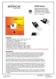
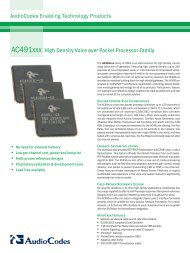
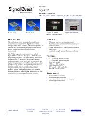
***12x12.5Double***12x12.5Single12x12.5 Single12x12.5 Double<strong>Line</strong> <strong>Card</strong>, 12x12.5 mmCLG : StandardP/NNominalVoltageESRCapacitance Max AllowedLCLength (L) Width (W) Height (H) Pitch (P) Weight(Volt) (mΩ) (mF) (µA) (mm) (mm) (mm) (mm) (gram)CLG03P012L12 * 3.5 600 12 3 12 12.5 2.4 8.0 ** 1.3CLG04P010L12 4.2 720 10 3 12 12.5 2.6 8.0 1.4CLG05P008L12 5.5 1000 8 3 12 12.5 3.1 8.0 1.5CLG06P007L12 6.3 1200 7 3 12 12.5 3.4 8.0 1.6CLG03P025L12 3.5 300 25 6 12 12.5 3.4 8.0 1.6CLG04P020L12 4.2 360 20 6 12 12.5 3.9 8.0 1.7CLG05P016L12 5.5 500 16 6 12 12 4.8 8.0 1.8CLG06P012L12 6.3 600 12 6 12 12.5 5.3 8.0 1.9CLC : Low LeakageP/NNominalVoltageESRCapacitance Max AllowedLCLength (L) Width (W) Height (H) Pitch (P) Weight(Volt) (mΩ) (mF) (µA) (mm) (mm) (mm) (mm) (gram)CLC03P012L12 * 3.5 600 12 1.5 12 12.5 2.4 8.0 ** 1.3CLC04P010L12 4.2 720 10 1.5 12 12.5 2.9 8.0 1.4CLC03P025L12 3.5 330 25 3 12 12.5 3.7 8.0 1.6CLC04P020L12 4.2 390 20 3 12 12.5 4.2 8.0 1.7Notes: * For capacitors with flat leads, P/N is CLG__P__F12 instead of CLG__P__L12.** For capacitors with flat leads, pitch is 7.3 mm instead of 8 mm.*** “Double”- a supercapacitor built of two parallel connected “Single” cells.Revision: 13-02-13Subject to change without notice5
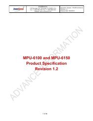
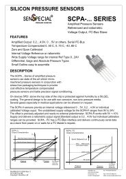
17x17.5 Double**17x17.5 Double**17x17.5 Single17x17.5 Single<strong>Line</strong> <strong>Card</strong>, 17x17.5 mmCLG : StandardP/NNominalVoltageESRCapacitance Max AllowedLCLength( L) Width (W) Height (H) Pitch (P) Weight(Volt) (mΩ) (mF) (µA) (mm) (mm) (mm) (mm) (gram)CLG02P040L17* 2.1 180 40 6 17 17.5 2.2 11.0 2.6CLG03P025L17 3.5 300 25 6 17 17.5 2.4 11.0 2.7CLG04P020L17 4.2 360 20 6 17 17.5 2.6 11.0 2.8CLG05P015L17 5.5 480 15 6 17 17.5 3.1 11.0 3.0CLG02P080L17 2.1 90 80 12 17 17.5 2.5 11.0 3.2CLG03P050L17 3.5 150 50 12 17 17.5 3.4 11.0 3.3CLG04P040L17 4.2 180 40 12 17 17.5 3.9 11.0 3.4CLG05P030L17 5.5 240 30 12 17 17.5 4.8 11.0 3.6CLK : Extra CapacitanceP/NNominalVoltageESR Capacitance Max AllowedLCLength (L) Width (W) Height (H) Pitch (P) Weight(Volt) (mΩ) (mF) (µA) (mm) (mm) (mm) (mm) (gram)CLK03P050L17 3.5 310 50 6 17 17.5 2.9 11.0 2.7CLK04P040L17 4.2 370 40 6 17 17.5 3.2 11.0 2.8CLK05P030L17 5.5 490 30 6 17 17.5 3.8 11.0 3.0CLK03P100L17 3.5 155 100 12 17 17.5 4.5 11.0 3.3CLK04P080L17 4.2 185 80 12 17 17.5 5.2 11.0 3.4CLK05P060L17 5.5 245 60 12 17 17.5 6.3 11.0 3.6Notes: * For capacitors with flat leads, P/N is CLG__P__F17 instead of CLG__P__L17.** “Double”- a supercapacitor built of two parallel connected “Single” cells.Revision: 13-02-13Subject to change without notice6
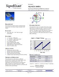
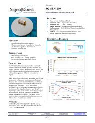
28x17.5 Single28x17.5 Double **28x17.5 Single28x17.5 Double **<strong>Line</strong> <strong>Card</strong>, 28x17.5 mmCLG : StandardP/NNominalVoltageESRCapacitance Max AllowedLCLength (L) Width (W) Height (H) Pitch (P) Weight(Volt) (mΩ) (mF) (µA) (mm) (mm) (mm) (mm) (gram)CLG03P060L28* 3.5 130 60 10 28 17.5 2.4 11.0 4.3CLG04P050L28 4.2 150 50 10 28 17.5 2.6 11.0 4.5CLG05P040L28 5.5 200 40 10 28 17.5 3.1 11.0 4.8CLG06P035L28 6.3 230 35 10 28 17.5 3.4 11.0 5.3CLG12P015L28 12 445 15 10 28 17.5 5.4 11.0 6.4CLG03P120L28 3.5 65 120 20 28 17.5 3.4 11.0 5.3CLG04P100L28 4.2 75 100 20 28 17.5 3.9 11.0 5.4CLG05P080L28 5.5 100 80 20 28 17.5 4.8 11.0 5.7CLG06P070L28 6.3 115 70 20 28 17.5 5.4 11.0 6.3CLG12P030L28 12 225 30 20 28 17.5 9.0 11.0 7.1CLK : Extra CapacitanceP/NNominalVoltageESRCapacitance Max AllowedLCLength (L) Width (W) Height (H) Pitch (P) Weight(Volt) (mΩ) (mF) (µA) (mm) (mm) (mm) (mm) (gram)CLK03P120L28* 3.5 170 120 10 28 17.5 3.1 11.0 4.3CLK04P100L28 4.2 190 100 10 28 17.5 3.4 11.0 4.5CLK05P080L28 5.5 240 80 10 28 17.5 3.8 11.0 4.8CLK12P030L28 12 460 30 10 28 17.5 6.8 11.0 7.8CLK03P240L28 3.5 85 240 20 28 17.5 4.8 11.0 5.3CLK04P200L28 4.2 95 200 20 28 17.5 5.3 11.0 5.4CLK05P160L28 5.5 120 160 20 28 17.5 6.5 11.0 5.7CLK12P060L28 12 230 60 20 28 17.5 12.0 11.0 8.1Notes: * For capacitors with flat leads, P/N is CLG__P__F28 instead of CLG__P__L28.** “Double”- a supercapacitor built of two parallel connected “Single” cells.Revision: 13-02-13Subject to change without notice7
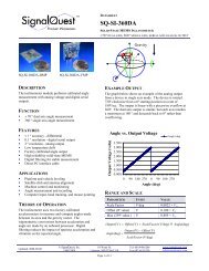
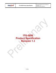
48x30<strong>Line</strong> <strong>Card</strong>, 48x30 mmCLG : StandardP/NNominalVoltageESRCapacitance Max AllowedLCLength (L) Width (W) Height (H) Pitch (P) Weight(Volt) (mΩ) (mF) (µA) (mm) (mm) (mm) (mm) (gram)CLG02P700L48* 2.1 18 700 65 48 30.5 3.3 22.3 18.5CLG03P420L48 3.5 30 420 65 48 30.5 4.2 22.3 19.5CLG04P350L48 4.2 36 350 65 48 30.5 4.7 22.3 20.0CLG05P280L48 5.5 48 280 65 48 30.5 5.6 22.3 21.2CLG06P245L48 6.3 54 245 65 48 30.5 6.1 22.3 21.7CLG09P165L48 9 78 165 65 48 30.5 8.0 22.3 25.2CLG12P120L48 12 108 120 65 48 30.5 10.0 22.3 31.1Notes: * For capacitors with flat leads, P/N is CLG__P__F48 instead of CLG__P__L48.Revision: 13-02-13Subject to change without notice8
Electrical Rating TableCLG Ratings Nominal Minimum MaximumCapacitance tolerance -20% +80%Operating Temp. 25°C -40°C+70°C (all products)+85°C (CLK series)Storage Temp. 25°C -10°C +35°CSurge voltage +15%Pulse currentNo limitRevision: 13-02-13Subject to change without notice9
Mechanical DimensionsThrough Hole Leads, SingleP/NV[V]ESR[mΩ]Cap[mF]LC[µA]L[mm]W[mm]H[mm]P[mm]CLG03P012L123.56001231212.52.48CLG04P010L124.27201031212.52.68CLG03P025L173.53002561717.52.411CLG04P020L174.23602061717.52.611CLG03P060L283.513060102817.52.411CLG04P050L284.215050102817.52.611Revision: 13-02-13Subject to change without notice01
Mechanical DimensionsThrough Hole Leads, DoubleP/NV[V]ESR[mΩ]Cap[mF]LC[µA]L[mm]W[mm]H[mm]P[mm]CLG03P025L123.53002561212.53.48CLG04P020L124.23602061212.53.98CLG03P050L173.515050121717.53.411CLG04P040L174.218040121717.53.911CLG03P120L283.565120202817.53.411CLG04P100L284.275100202817.53.911CLG03P420L483.520420654830.53.422.3CLG04P350L484.225350654830.53.922.3Revision: 13-02-13Subject to change without notice00
Mechanical DimensionsFlat Leads, SingleP/NV[V]ESR[mΩ]Cap[mF]LC[µA]L[mm]W[mm]L1[mm]H[mm]P[mm]CLG03P012F12 3.5 6001231212.52.7CLG04P010F12 4.2 7201031212.52.7CLG03P025F17 3.5 3002561717.53.7CLG04P020F17 4.2 3602061717.53.7CLG03P060F28 3.5 13060102817.53.7CLG04P050F28 4.2 15050102817.53.72.42.62.42.62.42.67.37.311111111Revision: 13-02-13Subject to change without notice02
Mechanical DimensionsFlat Leads, DoubleP/NV[V]ESR[mΩ]Cap[mF]LC[µA]L[mm]W[mm]L1[mm]H[mm]P[mm]CLG03P025F12 3.5 3002561212.52.7CLG04P020F12 4.2 3602061212.52.7CLG03P050F17 3.5 15050121717.53.7CLG04P040F17 4.2 18040121717.53.7CLG03P120F28 3.5 65120202817.53.7CLG04P100F28 4.2 75100202817.53.73.43.93.43.93.43.97.37.311111111Revision: 13-02-13Subject to change without notice03
Cell StructureWrapping MaterialSeparatorRimSealing MaterialLeadsStainless Steel Shell Current Collector Activated Carbon Electrode<strong>Cellergy</strong>’s products typically do not have polarity as the electrodes are symmetrical.Voltage is applied to the capacitors during <strong>Cellergy</strong>’s qualification tests and the capacitor may be sent tothe customer with residual voltages remaining after shorting the cells.Accordingly plus / minus signs are designated in accordance with <strong>Cellergy</strong> Q&R procedures.Revision: 13-02-13Subject to change without notice04
Packing (CL...12)Supercapacitors per traySupercapacitor type112 Single56 DoubleCL...12 tray weight : 31 gr.CL...12 tray material: Transparent PVCRevision: 13-02-13Subject to change without notice05
Packing (CL...17)Supercapacitors per traySupercapacitor type72 Single36 DoubleCL...17 tray weight : 30 gr.CL...17 tray material: Transparent PVCRevision: 13-02-13Subject to change without notice06
Packing (CL...28)Supercapacitors per traySupercapacitor type60 Single30 DoubleCL...28 tray weight : 32 gr.CL...28 tray material: Transparent PVCRevision: 13-02-13Subject to change without notice07
Qualification Test SummaryNo. Item Test Method Limits1 Initial capacitance2Initial leakagecurrent3 Initial ESRCharge to rated voltage for 10min. discharge at constantcurrent, C=Idt/dv (details in the page 19)Charge to rated voltage 12 hr measure current (details inthe page 19)Measure @ 1 KHz, Voltage 20mV amplitude, (details in thepage 19)+80% / -20% of rated valueWithin Limits ( refer to max. LCvalues in line card table)+20% / -50% of rated value4 Endurance1000 hrs at 70°C at rated voltage(500 hrs at 70°C for 12x12 foot print products)(500 hrs at 85°C for CLK series products)Cool to RT measure: ESR,LC,CLC < 3.0x rated valueCap > 0.7x rated valueESR < 3.0x rated value5 Humidity life1000 hrs at 40°C 90-95% humidity no voltageCool to RT measure: ESR,LC,CLC < 1.5x rated valueCap > 0.9x rated valueESR < 1.5x rated value6Robustness ofterminationsIn accordance with IEC 62391-1 and subjected to test Ub:bending of IEC 60068-2-21, method 2; two or more bends inan angle of 90º in the same directionLC : rated valueCap : rated valueESR : rated valueNo visual damage7 Surge voltageApply 15% voltage above rated voltage for 10 sec short cells10 seconds repeat procedure 1000 times measure ESR,LC,CLC : < 2.0x rated valueCap : > 0.7x rated valueESR: < 2.0x rated value8TemperaturecyclingEach cycle consist of following steps:1) Place supercapacitor in cold chamber (–40C) hold for30 min2) Transfer supercapacitor to hot chamber (+70C) in 2to 3 minutes.3) Hold supercapacitor in hot chamber for 30 minNumber of cycles: 5LC : < 1.5x rated valueCap: > 0.9x rated valueESR: < 1.5x rated value9 VibrationFrequency = 10 to 55 HzAmplitude of vibration: 0.75 mm2 hours each in three directions, ( Total 6 hours )LC : rated valueCap : rated valueESR : rated valueNo visual damageRevision: 13-02-13Subject to change without notice08
Measuring Method of Characteristics1) Charge the capacitor to nominal voltage (V_nom) for 30 minutes by constant voltage.2) Discharge the capacitor with constant current (I_dsch) from voltage (V1 = 80% of V_nom) tothe voltage (V2 = 40% of V_nom) while measure discharge time (Δt).3) Calculate capacitance using following formulaSAECWVConstant CurrentDischargeE = V_nomV (Volt)V_nomV1 = 0.8 x V_nomInitial Capacitance(Based on international standardIEC 62391-1)ΔtV2 = 0.4 x V_nomt (sec)Cap = I_dsch*(Δt)/(V1-V2)According to international standard IEC 62391-1, the suggested I_dsch values are:CLGFamilyL12L12L17L17L28L28L48L48Max.allowedLeakageCurrent3uA6uA6uA12uA10uA20uA30uA60uAI_dsch2 mA5 mA5 mA10 mA10 mA20 mA30 mA60 mAInitial ESR @ 1Khz1) Measure ESR by HIOKI Model 3560 AC Low Ohmmeter(Equivalent SeriesResistance)1) Apply Nominal voltage to the capacitor.2) Measure Vr after 12±1 hours.3) Calculate current using following formula.Initial LeakageCurrentRevision: 13-02-13Subject to change without notice09
ESR (mOhm)Capacitance (mF)Typical Capacitor CharacteristicsESR vs. TemperatureESR vs. Temperature CLGXXPXXXL28120010008006004002000-40 -20 0 20 40 60Temperature (C)CLG03P060L28CLG03P120L28CLG04P050L28CLG05P040L28CLG05P080L28Capacitance vs. TemperatureCapacitance vs. Temperature CLGXXPXXXL2825020015010050CLG04P050L28CLG03P060L28CLG05P040L28CLG05P080L28CLG03P120L280-40 -20 0 20 40 60Temperature (C)Capacitance vs. FrequencyRevision: 13-02-13Subject to change without notice21
Part 2: User Manual1. BackgroundFilm capacitors store charge by means of two layers of conductive film that are separatedby a dielectric material. The charge accumulates on bothconductive film layers, yet remains separated due to the dielectric between the conductivefilms.Electrolytic capacitors are composed of metal to which is added a thin layer of nonconductivemetal oxide which serves as the dielectric.These capacitors have an inherently larger capacitance than that of standard film capacitors.In both cases the capacitance is generated by electronic charge and therefore the powercapability of these types of capacitors is relatively high while theenergy density is much lower.The Electrochemical Double Layer Capacitor (EDLC) or Super Capacitor is a form ofhybrid between conventional capacitors and the battery.The electrochemical capacitor is based on the double layer phenomenaoccurring between a conductive solid and a solution interphase.The capacitance, coined the "double layer capacitance", is the result of charge separationin the interphase. On the solid electrode, electronic charge isaccumulated and in the solution counter charge is accumulated in the form of ioniccharge.The EDLC embodies high power and high energy density (Fig. 1).Fig. 1Revision: 13-02-13Subject to change without notice20
Electrochemical CapacitorsThe operating principle of the super capacitor is similar to that of a battery. Pairs ofelectrodes are separated by an ionic conductive, yet electricallyinsulating, separator (Fig. 2). When a super capacitor is charged, electronic chargeaccumulates on the electrodes (conductive carbon) and ions (from the electrolyte) ofopposite charge approach the electronic charge.This phenomenon is coined "the double layer phenomenon".The distance between the electronic and the ionic charges is very small, roughly 1 nanometer,yet electronic tunneling does not occur.Between charging and discharging, ions and electrons shift locations.In the charged state a high concentration of ions will be located along theelectronically charged carbon surface (electrodes).As the electrons flow through an external discharge circuit, slower moving ions willshift away from the double layer. During EDLC cycling electrons and ions constantlymove in the capacitor, yet no chemical reaction occurs.Therefore electrochemical capacitors can undergo millions of charge anddischarge cycles. This phenomenon which occurs with carbon electrodes of very highsurface area and a three-dimensional structure, leads to incredibly high capacitanceas compared to standard capacitors.One can envision the model of the EDLC as two capacitors formed by the solid(carbon) liquid (electrolyte) interphase separated by a conductive ionicmembrane. An equivalent electronic model is two capacitors in a seriesconnection (Fig. 3) where Cdl is the capacitance of each electrode; Rp is theparallel resistance to the electrode, Rs is the resistance of the separator.We conclude that the energy density of electrochemical capacitors is higher than thatof electrolytic capacitors, and therefore they have applicability for systems with lowerfrequency requirements.Current CollectorAnodeSeparatorCathodeFig. 2Fig. 3Revision: 13-02-13Subject to change without notice22
<strong>Cellergy</strong>’s TechnologyBy use of a unique patented production and manufacturing process,<strong>Cellergy</strong> has developed a small footprint, low Equivalent Series Resistance(ESR), high frequency EDLC capable of storing relatively large amounts ofenergy.The development is based on an innovative printing technology allowing theproduction of EDLC’s in many different sizes with varied dimensions andshapes.In fact, <strong>Cellergy</strong> produces one of the smallest low ESR footprint EDLC's onthe market today.Since the patented printing technology is based on conventional printingtechniques, the manufacturing process is simple and unique, and it is possibleto manufacture large wafers of EDLC's.The basis of the technology is a printable aqueous electrode paste based on ahigh surface area carbon paste that is printed in an electrode matrixstructure on an electronically conductive film.The electrodes are then encapsulated with a porous ionic conductingseparator and another electrode matrix is then printed on the separator.This bipolar printing process is repeated as many times as required enablingus to tailor our product to the specifications of the end user.The finished wafer is then cut into individual EDLC's that are then packaged.<strong>Cellergy</strong>'s EDLC's boasts low equivalent series resistance as well as a lowleakage current due to our unique encapsulation technology and electrodecomposition.<strong>Cellergy</strong>'s EDLC's require no cell balancing or de-rating.The combination of the separator and carbon paste lead to the capability ofvery high power bursts within low milli-second pulse widths.<strong>Cellergy</strong>’s technology is based on aqueous components that are allenvironmentally friendly and non-toxic. Though the system is water based,the capacitor can work at temperatures between -40°C and 70°C.This working temperature range is achieved by the unique water basedelectrolyte that impregnates the high surface carbon.Because the chemistry of the system is based on water, the performance of<strong>Cellergy</strong>'s EDLC's is not affected by humidity.Revision: 13-02-13Subject to change without notice23
Application Notes for EDLC<strong>Cellergy</strong>'s super capacitors offer high power and high energy.This characteristic coupled with a battery offer the designer a uniqueopportunity to solve power related issues.The following table lists the characteristics of the EDLC (Table 1):Table 1CharacteristicsWorking VoltageDe-ratingCapacitanceFoot printOperating TemperaturesESRSafetyPowerPolarityNumber of charge/dischargecycles1.4-12 voltsNot required10-100's of mF12x12.5mm, 17x17.5mm, 28x17.5mm,48x30.5mm-40°C to +70°C CLG, CLC-40°C to +85°C CLK10's-100's mEnvironmentally friendly materials,No toxic fumes upon burning10's of Watts, short pulse widthsNo polarityOver 500000Revision: 13-02-13Subject to change without notice24
Voltage DropTwo main factors affect the voltage drop of all capacitors including EDLC's.The first voltage drop is defined as the Ohmic voltage drop.The capacitor has an internal resistance defined as ESR (Equivalent Series Resistance).As current flows through the capacitor, a voltage drop occurs that obeys Ohmslaw. This voltage drop is instantaneous and will diminish themoment that no current is drawn.The second voltage drop (capacitance related voltage drop) is due tocapacitor discharge.The voltage of the capacitor is directly proportional to the chargeaccumulated in the capacitor. During current discharge, capacitance isconsumed (current emitting from the capacitor) thus causing a linearvoltage decrease in the capacitor. When the current is stopped, the voltage of thecapacitor indicates the charge left in the capacitor. The combination of the Ohmicrelated voltage drop and the capacitance related voltage drop determine theactual working voltage window of an EDLC under drain conditions (Fig. 4).V1V2VoltagewindowV3t1t2Fig. 4Pulse widthOhmic voltage drop = V1-V2=Ipulse*ESRCapacitance related voltage drop = V2-V3= Ipulse*(t2-t1)/CWorking voltage window = V1-V3= Ipulse*ESR+ Ipulse*(t2-t1)/C*Where C is CapacitanceRevision: 13-02-13Subject to change without notice25
EDLC and Battery CouplingUnder drain conditions, a battery undergoes a voltage drop similarly to theEDLC. Because of many physical and chemical constraints, thebattery often cannot supply the power required while still retaining itsopen circuit voltage.The working voltage of the battery reflects the load on the battery, thus thelarger the voltage drop of the battery the larger the load on thebattery.Many difficulties are encountered by the designer planning the online powerdemand of a system, mainly because the power of the batteries is limited.If the battery must supply high power at short pulse widths, the voltagedrop may be too great to supply the power and voltage required by the endproduct (cutoff voltage).The large load on the battery may decrease the useful energy stored in thebattery and even may harm the battery and shorten its work life.This problem may be resolved by connecting the battery in parallel to anEDLC (Fig. 5).Fig. 5Revision: 13-02-13Subject to change without notice26
VoltageEDLC and Battery Coupling (Continued)Under conditions of high power and short duration current pulses, a voltagedamping effect will be achieved. The voltage drop of thebattery will be decreased resulting in better energy management andsuperior energy density of the battery (Fig. 6).The power supplied will be produced by both the EDLC and thebattery, and each will supply the relative power inversely to its own ESR.The inefficiency of batteries at lower temperatures is well known.The capacitance of most batteries decreases with decreasingtemperatures.This decrease is due to the slow kinetics of the chemical reaction in thebattery which increases the internal resistance of the battery.At low temperatures, the voltage drop of the battery increases andreduces the usefulness of the battery. This voltage drop can bereduced greatly by coupling of the battery and the EDLC.In conclusion, coupling the battery and EDLC results in superior powermanagement for many short interval and high powerapplications.CurrentPulse WidthBattery AloneBattery +<strong>Cellergy</strong>’s CapacitorFig. 6Revision: 13-02-13Subject to change without notice27
Distinct Applications for <strong>Cellergy</strong>'s Super CapacitorsExtending battery lifetimes – by connecting a primary battery inparallel to <strong>Cellergy</strong>’s capacitor, the designer can reduce the voltage dropduring a high current pulse.Extending secondary battery operation - Reducing voltage drop at lowtemperatures (-40°C).CF, PCMCIA <strong>Card</strong>s - <strong>Cellergy</strong>'s EDLC overcome the current limitation encounteredwhen connecting boards in an application utilizing batteries.Backup or current booster for mechanical applications such as a DC motor.Extending the battery lifetime of digital cameras.Rechargeable backup power source for microprocessors, static RAM's andDAT.AMR – Automatic Meter Readings.GPS-GSM Modules.Active RFIDWireless Sensors NetworkSSDMedical Micro PumpIndustrial PDACamera FlashEnergy HarvestingRevision: 13-02-13Subject to change without notice28
Manual SolderingUpon using a soldering iron, it should not touch the cell body.Temperature of the soldering iron should be less than 410℃ (leaded solderingprofile) or 435℃ (lead free soldering profile) .Soldering time for terminals should be less than 5 seconds or 3 secondsrespectively.Revision: 13-02-13Subject to change without notice29
Handling Cautions1) Do not apply more than rated voltage.If you apply more than rated voltage, <strong>Cellergy</strong> electrolyte will be electrolyzedand the super capacitors ESR may increase.2) Do not use <strong>Cellergy</strong> for ripple absorption.3) Operating temperature and lifeGenerally, <strong>Cellergy</strong> has a lower leakage current, longer back-up timeand longer life in the low temperature range i.e. the room temperature.It will have a higher leakage current and a shorter life at elevated temperatures.Please design the <strong>Cellergy</strong> such that is not adjacent to heat emitting elements.4) Short-circuit <strong>Cellergy</strong>You can short-circuit between terminals of <strong>Cellergy</strong> without a resistor.However when you short-circuit frequently, please consult us.5) StorageIn long term storage, please store <strong>Cellergy</strong> in following condition;1) TEMP. : -10 ~ +35 °C2) HUMIDITY : 45 ~ 75 %RH3) NON-DUST6) Do not disassemble <strong>Cellergy</strong> products. It contains electrolyte.7) The tips of <strong>Cellergy</strong> terminals are very sharp. Please handle with care.8) Reflow process is not recommended for <strong>Cellergy</strong> capacitors.NoteThe <strong>Cellergy</strong> EDLC is a water based component. Extended use of the EDLC at elevatedtemperatures may cause evaporation of water leading to ESR increase.Revision: 13-02-13Subject to change without notice31
Contact :7 Hauman St. South Industrial Zone Migdal Haemek P.O.B 631 23105 ISRAELPhone:+972-4-6544300, Fax:+972-4-6542764