RS-1000 Manual - kamery airlive airlivecam
RS-1000 Manual - kamery airlive airlivecam
RS-1000 Manual - kamery airlive airlivecam
- No tags were found...

You also want an ePaper? Increase the reach of your titles
YUMPU automatically turns print PDFs into web optimized ePapers that Google loves.
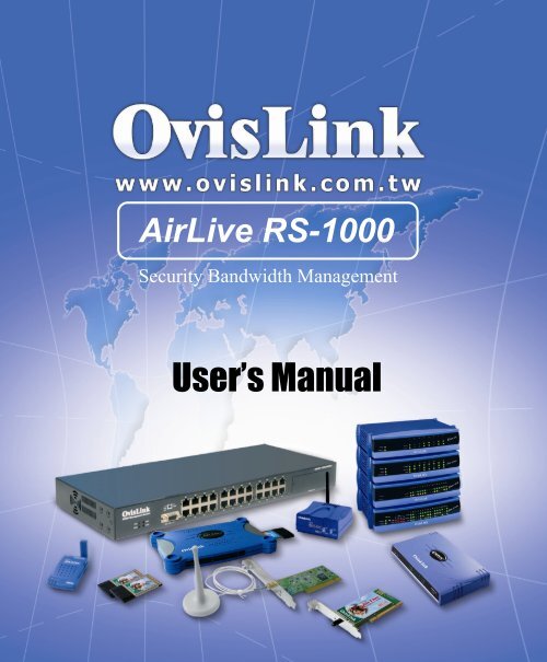
AirLive <strong>RS</strong>-<strong>1000</strong>Security Bandwidth ManagementUser’s <strong>Manual</strong>
ContentsSystem 1Admin3Setting7Date/Time16Language18Permitted IP19Multiple NAT23Hack Alert28Route Table31DHCP35Host Table36Dynamic DNS37Logout42
Software Update43Interface 44Address 54LANLAN GroupWANWAN Group55596367Service 71Pre-definedCustomGroup727378Schedule 82QoS 87Authentication 92Policy 97
OutgoingIncoming98105Content Filtering 113URL BlockingGeneral Blocking114119Virtual Server 120Mapped IPVirtual Server122126LOG 134Traffic LogEvent LogConnection LogLog Backup135138141144Alarm 147Traffic Alarm148
Event Alarm151Accounting Report 154OutboundInbound156162Statistics 168WAN StatisticsPolicy Statistics170171Status 173Interface StatusARP TableDHCP Clients174176177Setup Examples 178
SystemThe Security Bandwidth Manager Administration and monitoring control is set by the SystemAdministrator. The System Administrator can add or modify System settings and monitoringmode. The sub Administrators can only read System settings but not modify them. In System,the System Administrator can:1. Add and change the sub Administrator’s names and passwords;2. Back up all Security Bandwidth Manager settings into local files;3. Set up alerts for Hackers invasion.What is System?“System” is the managing of settings such as the privileges of packets that pass through theSecurity Bandwidth Manager and monitoring controls. Administrators may manage, monitor,and configure Security Bandwidth Manager settings. All configurations are “read-only” for allusers other than the Administrator; those users are not able to change any settings for theSecurity Bandwidth Manager.Admin: has control of user access to the Security Bandwidth Manager. He/she canadd/remove users and change passwords.Setting: The Administrator may use this function to backup Security Bandwidth Managerconfigurations and export (save) them to an “Administrator” computer or anywhere on thenetwork; or restore a configuration file to the device; or restore the Security BandwidthManager back to default factory settings. Under Setting, the Administrator may enablee-mail alert notification. This will alert Administrator(s) automatically whenever the SecurityBandwidth Manager has experienced unauthorized access or a network hit (hacking orflooding). Once enabled, an IP address of a SMTP (Simple Mail Transfer protocol) Server isrequired. Up to two e-mail addresses can be entered for the alert notifications.Date/Time: This function enables the Security Bandwidth Manager to be synchronized eitherwith an Internet Server time or with the client computer’s clock.Language: Both Chinese and English are supported in the Security Bandwidth Manager.1
Multiple NAT Multiple NAT allows local port to set multiple subnet works and connect withthe Internet through different WAN IP Addresses.Address:Enables the Administrator to authorize specific internal/external IP address(s forManager.Hack Alert When abnormal conditions occur, the Security Bandwidth Manager will send ane-mail alert to notify the Administrator, and also display warning messages in the Eventwindow of Alarm.Route Table Use this function to enable the Administrator to add static routes for thenetworks when the dynamic route is not efficient enough.DHCP Administrator can configure DHCP (Dynamic Host Configuration Protocol) settingsfor the LAN (LAN) network.Dynamic DNS The Dynamic DNS (require Dynamic DNS Service) allows you to alias adynamic IP address to a static hostname, allowing your device to be more easily accessed byspecific name. When this function is enabled, the IP address in Dynamic DNS Server will beautomatically updated with the new IP address provided by ISPLogout Administrator logs out the Security Bandwidth Manager. This function protectsyour system while you are away.Software Update The administrator can update the device’s software with the latest version.Administrators may visit distributor’s web site to download the latest firmware.Administrators may update the device firmware to optimize its performance and keep up withthe latest fixes for intruding attacks.2
AdminOn the left hand menu, click on Setup, and then select Admin below it. The current list ofAdministrator(s) shows up.!!Figure1-1Settings of the Administration tableAdministrator Name: The username of Administrators for the Security Bandwidth Manager.The user admin cannot be removed.Privilege: The privileges of Administrators (Admin or Sub Admin)The username of the main Administrator is Administrator with read / write privilege.Sub Admins may be created by the Admin by clicking New Sub Admin. Sub Adminshave read only privilege.Configure: Click Modify to change the “Sub Administrator’s” password and click Removeto delete a “Sub Administrator.”3
Changing the Main/Sub-Administrator’s PasswordStep 1. The Modify Administrator Password window will appear. Enter in the requiredinformation:" Password: enter original password." New Password: enter new password" Confirm Password: enter the new password again.Step 2. Click OK to confirm password change or click Cancel to cancel it.Figure1-24
Adding a new Sub AdministratorStep 1. In the Add New Sub Administrator window:" Sub Admin Name: enter the username of new Sub Admin." Password: enter a password for the new Sub Admin." Confirm Password: enter the password again.Step 2. Click OK to add the user or click Cancel to cancel the addition.Figure 1-35
Removing a Sub AdministratorStep 1. In the Administration table, locate the Administrator name you want to edit, andclick on the Remove option in the Configure field.Step 2. The Remove confirmation pop-up box will appear. Click OK to remove that SubAdmin or click Cancel to cancel.Figure1-4 Remove Sub Admin6
SettingsThe Administrator may use this function to backup Security Bandwidth Managerconfigurations and export (save) them to an “Administrator” computer or anywhere on thenetwork; or restore a configuration file to the device; or restore the Security BandwidthManager back to default factory settings.Entering the Settings windowClick Setting in the System menu to enter the Settings window. The Bandwidth ManagerConfiguration settings will be shown on the screen.!!Figure1-5 Setting7
Exporting Security Bandwidth Manager settingsStep 1. Under Bandwidth Manager Configuration, click on the Download button nextto Export System Settings to Client.Step 2. When the File Download pop-up window appears, choose the destination placeto save the exported file. The Administrator may choose to rename the file ifpreferred.Figure1-6 Select the location where the exported files to be saved8
Importing Security Bandwidth Manager settingsUnder Bandwidth Manager Configuration, click on the Browse button next to ImportSystem Settings. When the Choose File pop-up window appears, select the file whichcontains the saved Security Bandwidth Manager Settings, then click OK.Click OK to import the file into the Security Bandwidth Manager or click Cancel to cancelimporting.Figure1-7 Location and filename for saving imported file9
Restoring Factory Default SettingsStep 1. Select Reset Factory Settings under Bandwidth Manager Configuration.Click OK at the bottom-right of the screen to restore the factory settings.Figure1-8 Select Reset Factory Settings10
Enabling E-mail Alert NotificationStep 1. Select Enable E-mail Alert Notification under E-Mail Settings. This functionwill enable the Security Bandwidth Manager to send e-mail alerts to the SystemAdministrator when the network is being attacked by hackers or when emergencyconditions occur.Step 2. SMTP Server IP: Enter SMTP server’s IP address.Step 3. E-Mail Address 1: Enter the first e-mail address to receive the alarm notification.Step 4. E-Mail Address 2: Enter the second e-mail address to receive the alarmnotification. (Optional)Click OK on the bottom-right of the screen to enable E-mail alert notification.Figure1-9 Enable E-mail Alert Notification11
Web Manager (WAN Interface) (Remote UI Manager)The administrator can change the port number used by HTTP port anytime.(Remote UI Manager)Step 1. Set Web Manager (WAN Interface). The administrator can change the portnumber used by HTTP port anytime.Figure1-10 Web Manager12
MTU (set networking packet length)The administrator can modify the networking packet length.Step 1. MTU Setting. Modify the networking packet length.Figure1-11 MTU13
To-Bandwidth Manager Packets LogOnce this function is enabled, every packet passing through the Firewall willbe recorded for the administrator to trace.Step 1. Select this option to the device’s To-Bandwidth Manager Packets Log. Oncethis function is enabled, every packet to this appliance will be recorded for systemmanager to trace.Figure1-12 Enable To Bandwidth Manager Packets Log14
Security Bandwidth Manager RebootOnce this function is enabled, the Security Bandwidth Manager will be rebooted.Reboot Security Bandwidth Manager: Click Reboot.A confirmation pop-up box will appear. Follow the confirmation pop-up box, click OK to restartSecurity Bandwidth Manager or click Cancel to discard changesFigure1-13 Reboot Security Bandwidth Manager15
Date/TimeSynchronizing the Bandwidth Manager with the System ClockAdmins can configure the Security Bandwidth Manager.s date and time by eithersyncing to an Internet Network Time Server (NTP) or by syncing to your computer.sclock.Follow these steps to sync to an Internet Time ServerStep 1. Enable synchronization by checking the box.Step 2. Click the down arrow to select the offset time from GMT.Step 3. Enter the Server IP Address or Server name with which you want tosynchronize.Step 4. Update system clock every 5 minutes You can set the intervaltime to synchronize with outside servers. If you set it to 0, it meansthe device will not synchronize automatically.Follow this step to sync to your computer’s clock.Step 1. Click on the Sync button.Click OK to apply the setting or click Cancel to discard changes.Figure1-14 System Time16
LanguageAdmins can configure the Security Bandwidth Manager Select the Language versionStep 1. Select the Language version (English Version/Traditional ChineseVersion or Simplified Chinese Version).Step 2. Click 【OK】to set the Language version or click Cancel to discardchanges.!!Figure1-15 Language Setting17
Permitted IPsOnly the authorized IP address is permitted to manage the Security BandwidthManager.!!Figure1-16 Permitted IP Address18
Add Permitted IP AddressStep 1. Click New Entry button.Step 2. In IP Address field, enter the LAN IP address or WAN IP address." IP address:Enter the LAN IP address or WAN IP address." Netmask:Enter the netmask of LAN/WAN." Ping:Select this to allow the external network to ping the IP Address of theFirewall." WebUI:Check this item, Web User can use HTTP to connect to the Settingwindow of Security BandWidth Manager.Step 3. Click OK to add Permitted IP or click Cancel to discard changes.Figure1-17 Add New Permitted IPs19
Modify Permitted IP AddressStep 1. In the table of Permitted IPs, highlight the IP you want to modify, and then clickModify.Step 2. In Modify Permitted IP, enter new IP address.Step 3. Click OK to modify or click Cancel to discard changes.Figure1-18 Modify Permitted IPs20
Remove Permitted IP addressesStep 1. In the table of Permitted IPs, highlight the IP you want to remove, and then clickRemove.Step 2. In Remove Permitted IP, enter new IP address.Step 3. In the confirm window, click OK to remove or click Cancel to discard changes.Figure1-19 Remove Permitted IPs21
Multiple NATMultiple NAT allows local port to set multiple subnetworks and connect with the Internetthrough different WAN IP Addresses.For instance:The lease line of a company applies several real IP Addresses 168.85.88.0/24,andthe company is divided into R&D department, service, sales department, procurementdepartment, accounting department, the company can distinguish each department bydifferent subnetworks for the purpose of convenient Manager. The settings are as thefollowing:1.R&D department subnetwork:192.168.1.11/24(Internal) #$ 168.85.88.253(WAN)2. Service department subnetwork:192.168.2.11/24(Internal) #$ 168.85.88.252(WAN)3.Sales department subnetwork: 192.168.3.11/24(Internal) #$ 168.85.88.251(WAN)4.Procurement department subnetwork 192.168.4.11/24(Internal) #$ 168.85.88.250(WAN)5.Accounting department subnetwork 192.168.5.11/24(Internal) #$ 168.85.88.249(WAN)The first department(R&D department) was set while setting interface IP, the other four oneshave to be added in Multiple NAT,after completing the settings, each department use thedifferent WAN IP Address to connect to the Internet. The settings of each department are asthe followingService IP Address:192.168.2.1Subnet Mask:255.255.255.0Default Gateway:192.168.2.11The other departments are also set by groups, this is the function of Multiple NAT.22
Multiple NAT settingsStep 1. Click Multiple NAT in the System menu to enter Multiple NAT window.!!Figure1-20 Multiple NATGlobal port interface IP Address:Global port IP Address.Local port interface IP Address:Local port IP Address and subnet Mask.Modify: Modify the settings of Multiple NAT. Click Modify to modify the parameters of MultipleNAT or click Delete to delete settings.23
Add Multiple NATStep 1. Click the Add button below to add Multiple NAT.Step 2. Enter the IP Address in the website name column of the new window." Global port interface IP Address: Select Global port IP Address." Local port interface IP Address: Enter Local port IP Address." Subnet Mask:Enter Local port subnet Mask.Step 3. Click OK to add Multiple NAT or click Cancel to discard changes.Figure1-21 Add Multiple NAT24
Modify Multiple NATStep 1. Find the IP Address you want to modify and click ModifyStep 2. Enter the new IP Address in Modify Multiple NAT window.Step 3. Click the OK button below to change the setting or click Cancel to discardchanges.Figure1-22 Modify Multiple NAT25
Delete Multiple NATStep 1. Find the IP Address you want to delete and click Delete.Step 2. A confirmation pop-up box will appear, click OK to delete the setting or clickCancel to discard changes.Figure1-23 Remove Multiple NAT26
Hacker AlarmThe Administrator can enable the device’s auto detect functions in this section. Whenabnormal conditions occur, the Security Bandwidth Manager will send an e-mail alert to notifythe Administrator, and also display warning messages in the Event window of Alarm.!!Auto Detect functionsFigure1-24 Hacker Alert" Detect SYN Attack: Select this option to detect TCP SYN attacks thathackers send to server computers continuously to block or cut down all theconnections of the servers. These attacks will prevent valid users fromconnecting to the servers. After enabling this function, the SystemAdministrator can enter the number of SYN packets per second that isallowed to enter the network/ Security Bandwidth Manager. Once the SYNpackets exceed this limit, the activity will be logged in Alarm and an email alertis sent to the Administrator. The default SYN flood threshold is set to 200Pkts/Sec .27
" Detect ICMP Flood: Select this option to detect ICMP flood attacks. Whenhackers continuously send PING packets to all the machines of the LANnetworks or to the Security Bandwidth Manager, your network is experiencingan ICMP flood attack. This can cause traffic congestion on the network andslows the network down. After enabling this function, the SystemAdministrator can enter the number of ICMP packets per second that isallowed to enter the network/ Security Bandwidth Manager. Once the ICMPpackets exceed this limit, the activity will be logged in Alarm and an email alertis sent to the Administrator. The default ICMP flood threshold is set to <strong>1000</strong>Pkts/Sec." Detect UDP Flood: Select this option to detect UDP flood attacks. A UDPflood attack is similar to an ICMP flood attack. After enabling this function,the System Administrator can enter the number of UDP packets per secondthat is allow to enter the network/Bandwidth Manager. Once the UDPpackets exceed this limit, the activity will be logged in Alarm and an email alertis sent to the Administrator. The default UDP flood threshold is set to <strong>1000</strong>Pkts/Sec ." Detect Ping of Death Attack: Select this option to detect the attacks oftremendous trash data in PING packets that hackers send to cause Systemmalfunction This attack can cause network speed to slow down, or even makeit necessary to restart the computer to get a normal operation." Detect Tear Drop Attack: Select this option to detect tear drop attacks.These are packets that are segmented to small packets with negative length.Some Systems treat the negative value as a very large number, and copyenormous data into the System to cause System damage, such as a shutdown or a restart." Detect IP Spoofing Attack: Select this option to detect spoof attacks.Hackers disguise themselves as trusted users of the network in Spoof attacks.They use a fake identity to try to pass through the Security BandwidthManager System and invade the network.28
" Filter IP Source Route Option: Each IP packet can carry an optional fieldthat specifies the replying address that can be different from the sourceaddress specified in packet’s header. Hackers can use this address field ondisguised packets to invade LAN networks and send LAN networks’ data backto them." Detect Port Scan Attack: Select this option to detect the port scans hackersuse to continuously scan networks on the Internet to detect computers andvulnerable ports that are opened by those computers." Detect Land Attack: Some Systems may shut down when receiving packetswith the same source and destination addresses, the same source port anddestination port, and when SYN on the TCP header is marked.Enable this function to detect such abnormal packets.After enabling the needed detect functions, click OK to activate the changes.29
Route TableIn this section, the Administrator can add static routes for the networks.Entering the Route Table screenStep 1. Click System on the left side menu bar, then click Route Table below it. TheRoute Table window appears, in which current route settings are shown.!!Figure1-25 Route TableRoute Table functions" Interface: Destination network , LAN or WAN 1 networks." Destination IP: IP address of destination network." NetMask: Netmask of destination network." Gateway: Gateway IP address for connecting to destination network." Configure: Change settings in the route table.30
Adding a new Static RouteStep 1. In the Route Table window, click the New Entry button.Step 2. In the Add New Static Route window, enter new static route information.Step 3. In the Interface field’s pull-down menu, choose the network to connect (LAN,WAN).Step 4. Click OK to add the new static route or click Cancel to cancel.Figure1-26 Add New Static Route31
Modifying a Static Route:Step 1. In the Route Table menu, find the route to edit and click the corresponding Modifyoption in the Configure field.Step 2. In the Modify Static Route window, modify the necessary routing addresses.Step 3. Click OK to apply changes or click Cancel to cancel it.Figure1-27 Modify Static Route32
Removing a Static RouteStep 1. In the Route Table window, find the route to remove and click the correspondingRemove option in the Configure field.Step 2. In the Remove confirmation pop-up box, click OK to confirm removing or clickCancel to cancel it.Figure1-28 Remove a Static Route33
DHCPIn the section, the Administrator can configure DHCP (Dynamic Host Configuration Protocol)settings for the LAN (LAN) network.Entering the DHCP windowClick System on the left hand side menu bar, then click DHCP below it. The DHCP windowappears in which current DHCP settings are shown on the screen.!!Figure1-29 Dynamic IP addressDynamic IP Address functions" Subnet : LAN network’s subnet" NetMask : LAN network’s netmask" Gateway: LAN network’s gateway IP address" Broadcast: LAN network’s broadcast IP address34
Enabling DHCP SupportStep 1. In the Dynamic IP Address window, click Enable DHCP Support.Domain Name: The Administrator may enter the name of the LAN network domain ifpreferred.DNS Server 1 : Enter the distributed IP address of DNS Server1.DNS Server 2 : Enter the distributed IP address of DNS Server2.WINS Server 1 : Enter the distributed IP address of WINS Server1.WINS Server 2 : Enter the distributed IP address of WINS Server2.Client IP Address Range 1: Enter the starting and the ending IP addressdynamically assigning to DHCP clients.Client IP Address Range 2: Enter the starting and the ending IP addressdynamically assigning to DHCP clients. (Optional)Step 2. Click OK to enable DHCP support.Figure1-30 Enable DHCP Support35
Adding a new Host TableSTEP 1.Select Host Table in Settings function and enter the following setting:" Click on New Entry" Host Name: The domain name of the server" Virtual IP Address: The virtual IP address that Host Table mapped to" Click OK and complete adding Host Table. (Figure1-31)Figure1-31 Add New Host Table WebUITo use Host Table, the user PC’s first DNS Server must be the same as the LAN Port orDMZ Port IP of Bandwidth Manager. That is, the default gateway.36
Dynamic DNSThe Dynamic DNS (require Dynamic DNS Service) allows you to alias a dynamic IP addressto a static hostname, allowing your device to be more easily accessed by specific name.When this function is enabled, the IP address in Dynamic DNS Server will be automaticallyupdated with the new IP address provided by ISP.!!Figure1-31 Dynamic DNSClick Dynamic DNS in the System menu to enter Dynamic DNS window.The nouns in Dynamic DNS window:!:Update Status【 Connecting; Update succeed; Update fail; Unidentified error】Domain name:Enter the password provided by ISP.WAN IP Address:IP Address of the WAN port.Modify: Modify dynamic DNS settings. Click Modify to change the DNS parameters; clickDelete to delete the settings.How to use dynamic DNS:The Security Bandwidth Manager provides 3 service providers, users have to register prior touse this function. For the usage regulations, see the providers’ websites.37
How to register:Firstly, Click Dynamic DNS in the System menu to enter Dynamic DNSwindow, then click Add button,on the right side of the service providers, click Register, theservice providers’ website will appear, please refer to the website for the way of registration.Click to link to the website selected on the left.Figure1-32 Setting up DDNS38
Add Dynamic DNS settingsStep 1. Click Add button.Step 2. Click the information in the column of the new window.Service providers:Select service providers.Register:to the service providers’ website.WAN IP Address:IP Address of the WAN port.% automatically fill in the WAN IP:Check to automatically fill in the WAN IP.。User Name:Enter the registered user name.Password:Enter the password provided by ISP(Internet Service Provider).Domain name:Your host domain name provided by ISP.Click OK to add dynamic DNS or click Cancel to discard changes.Figure1-33 Add New Dynamic DNS39
Modify dynamic DNSStep 1. Find the item you want to change and click Modify.Step 2. Enter the new information in the Modify Dynamic DNS window.Click OK to change the settings or click Cancel to discard changes.。Figure1-34 Modify Dynamic DNS40
Delete Dynamic DNSStep 1. Find the item you want to change and click Delete.Step 2. A confirmation pop-up box will appear, click OK to delete the settings or clickCancel to discard changes.Figure1-35 Remove Dynamic DNS41
LogoutStep 1. Select this option to the device’s Logout the Security Bandwidth Manager. Thisfunction protects your system while you are away.Step 2. Click Logout the Bandwidth Manager.Step 3. Click OK to logout or click Cancel to discard the change.!!Figure1-36 Logout42
Software UpdateUnder Software Update, the admin may update the device’s software with a newer software.You may acquire the current version number of software in Version Number. Administratorsmay visit distributor’s web site to download the latest version and save it in server’s hard disc.Step 1. Click Browse to select the latest version of Software.Step 2. Click OK to update software.!!Figure1-37 Software UpdateIt takes three minutes to update the software. The system will restart automatically afterupdating the software.43
InterfaceIn this section, the Administrator can set up the IP addresses for the office network. TheAdministrator may configure the IP addresses of the Internal (LAN) network, and the External(WAN) network. The netmask and gateway IP addresses are also configured in this section.In Interface section, the administrator can configure IP address, Netmask, and Gateway ofthe LAN network/ WAN network inside the office network, depending on the ISP selected.44
Entering the Interface menu:Step 1. Click on Configuration in the left menu bar.Step 2. Then click on Interface below it. The current settings of the interface addresseswill appear on the screen.Internal InterfaceUsing the Internal Interface, the Administrator sets up the Internal (LAN) network. TheInternal network will use a private IP scheme. The private IP network will not be routable onthe Internet.Transparent Mode:All the IP internetwork uses real IP.NAT Mode:All the IP Internetwork uses NAT (Network Address Translation), which allows theprivate IP internetworks use non-registered IP addresses to connect to the Internet.IP Address: The private IP address of the Firewall’s internal network is the IP address of theInternal (LAN) port of the Security Bandwidth Manager. The default IP address is192.168.1.1.Note:The IP Address of Internal Interface and the DMZ Interface is a private IP address only.If the new Internal IP Address is not 192.168.1.1, the Administrator needs to set the IPAddress on the computer to be on the same subnet as the Firewall and restart the System tomake the new IP address effective. For example, if the Firewall’s new Internal IP Address is172.16.0.1, then enter the new Internal IP Address 172.16.0.1 in the URL field of browser toconnect to Firewall.NetMask: This is the netmask of the internal network. The default netmask of the SecurityBandwidth Manager is 255.255.255.0.Ping: Select this to allow the internal network to ping the IP Address of the Firewall. If set toenable, the Security Bandwidth Manager will respond to ping packets from the internalnetwork.WebUI: Select this to allow the Security Bandwidth Manager WEBUI to be accessed from theInternal (LAN) network.45
!!46
ADSL user Interface settingPPPoE(External Interface)Step 1. Select Interface function in the menu bar.Step 2. Check the item PPPoE (ADSL User) below WAN Interface.Step 3. Enter each parameter of WAN Interface.!!Figure2-2 PPPoE ADSL User InterfaceFor PPPoE (ADSL User): This option is for PPPoE users who are required to enter ausername and password in order to connect, such as ADSL users.Current Status: Displays the current line status of the PPPoE connection.IP Address: Displays the IP Address of the PPPoE connectionUsername: Enter the PPPoE username provided by the ISP.Password: Enter the PPPoE password provided by the ISP.IP Address provided by ISP:Dynamic: Select this if the IP address is automatically assigned by the ISP.47
48Fixed: Select this if you were given a static IP address. Enter the IP address that is given toyou by your ISP.Upload/Download Bandwidth:The bandwidth your ISP provided. (Maximum bandwidth forUpload/Download Bandwidth is 10Mbps)Service-On-Demand:Auto Disconnect: The PPPoE connection will automatically disconnect after a length of idletime (no activities). Enter in the amount of idle minutes before disconnection. Enter ‘0’ ifyou do not want the PPPoE connection to disconnect at all.Ping: Select this to allow the external network to ping the IP Address of the Firewall. Thiswill allow people from the Internet to be able to ping the Firewall. If set to enable, the SecurityBandwidth Manager will respond to echo request packets from the external network.WebUI: Select this to allow the Security Bandwidth Manager WEBUI to be accessed from theExternal (WAN) network. This will allow the WebUI to be configured from a user on theInternet. Keep in mind that the Security Bandwidth Manager always requires a usernameand password to enter the WebUI.After completing the setting, click OK.
49For Dynamic IP Address (Cable Modem User): This option is for users who areautomatically assigned an IP address by their ISP, such as cable modem users. Thefollowing fields apply:IP Address: The dynamic IP address obtained by the Firewall from the ISP will be displayedhere. This is the IP address of the External (WAN) port of the Security Bandwidth Manager.MAC Address: This is the MAC Address of the Security Bandwidth Manager.User Name (Some ISPs may require):This is provided by your ISP.Hostname: This will be the name assign to the Security Bandwidth Manager. Some cablemodem ISP assign a specific hostname in order to connect to their network. Please enterthe hostname here. If not required by your ISP, you do not have to enter a hostname.Max. Upstream/Downstream Bandwidth: The bandwidth provided by ISP.(Upstream/Downstream can be up to 10Mbps)Renew: Requests for receiving the new WAN IP address.Release: Requests for releasing the obtained WAN IP address.Ping: Select this to allow the external network to ping the IP Address of the Firewall. Thiswill allow people from the Internet to be able to ping the Firewall. If set to enable, theSecurity Bandwidth Manager will respond to echo request packets from the external network.WebUI: Select this to allow the Security Bandwidth Manager WEBUI to be accessed from theExternal (WAN) network. This will allow the WebUI to be configured from a user on theInternet. Keep in mind that the Security Bandwidth Manager always requires a usernameand password to enter the WebUI.
50After setting all of the parameters, click OK button.!!Figure2-3 Dynamic IP Address (Cable Modem User)
For Static IP Address: This option is for users who are assigned a static IP Address fromtheir ISP. Your ISP will provide all the information needed for this section such as IP Address,Netmask, Gateway, and DNS. Use this option if you have more than one public IP Addressassigned to you.IP Address: Enter the static IP address assigned to you by your ISP. This will be the publicIP address of the External (WAN) port of the Security Bandwidth Manager.Netmask: This will be the Netmask of the external (WAN) network. (i.e. 255.255.255.0)Default Gateway: This will be the Gateway IP address.DNS Server 1/2: Enter the DNS 1/2 server provided by ISP. (See Note.)Max. Upstream Bandwidth/Max. Downstream Bandwidth: The bandwidth provided by ISP.(Upstream/Downstream can be up to 10Mbps)Ping: Select this to allow the external network to ping the IP Address of the Firewall. Thiswill allow people from the Internet to be able to ping the Firewall. If set to enable, theSecurity Bandwidth Manager will respond to echo request packets from the external network.WebUI: Select this to allow the Security Bandwidth Manager WEBUI to be accessed from theExternal (WAN) network. This will allow the WebUI to be configured from a user on theInternet. Keep in mind that the Security Bandwidth Manager always requires a usernameand password to enter the WebUI.After setting all of the interface address, click OK button.!!Figure2-4 WAN interface setup for Static IP Address51
52If you want to set up DNS Server, you have to go to Virtual Server function to map the real IPaddress from DNS server to the corresponding private IP address of internal DNS server.Enter the mapped IP address of internal server in DNS server address field.
For PPTP (European User Only): This option is for PPTP users who are required to enter ausername and password in order to connect, especially for European Users.Current Status: Displays the current line status of the PPTP connection.IP Address: Displays the IP Address of the PPTP connectionUsername: Enter the PPTP username provided by the ISP.Password: Enter the PPTP password provided by the ISP.Local IP: Select To obtain an IP address automatically or Use the following IP address.MAC Address: This is the MAC Address of the Bandwidth Manager.Hostname: This will be the name assign to the Bandwidth Manager. Please enter thehostname here. If not required by your ISP, you do not have to enter a hostname.Domain Name: This will be the domain name assign to the Bandwidth Manager.IP Address: Enter the IP address assigned to you by your ISP. This will be the public IPaddress of the External (WAN) port of the Bandwidth Manager.Netmask: This will be the Netmask of the external (WAN) network. (i.e. 255.255.255.0)Default Gateway: This will be the Gateway IP address.PPTP Gateway: This will be the PPTP Server IP address.Connect ID: Enter the phone number that provided and asked by some ISP. (Optional)Max. Upstream/Downstream Bandwidth: The bandwidth provided by ISP.(Upstream/Downstream can be up to 10Mbps)BEZEQ-ISRAEL: The selection especially for the user who wants to connect to Bezeq (theIsraeli phone company which doesn’t conform to the RFC protocol).Service-On-Demand:Auto Disconnect: The PPTP connection will automatically disconnect after a length of idletime (no activities). Enter in the amount of idle minutes before disconnection. Enter ‘0’ ifyou do not want the PPTP connection to disconnect at all.53
AddressThe Security Bandwidth Manager allows the Administrator to set Interface addresses of theLAN network, LAN network group, WAN network, WAN group.What is the Address Table?An IP address in the Address Table can be an address of a computer or a sub network. TheAdministrator can assign an easily recognized name to an IP address. Based on the networkit belongs to, an IP address can be an LAN IP address, WAN IP address . If the Administratorneeds to create a control policy for packets of different IP addresses, he can first add a newgroup in the LAN Network Group or the WAN Network Group and assign those IPaddresses into the newly created group. Using group addresses can greatly simplify theprocess of building control policies.With easily recognized names of IP addresses and names of address groups shown in theaddress table, the Administrator can use these names as the source address or destinationaddress of control policies. The address table should be built before creating control policies,so that the Administrator can pick the names of correct IP addresses from the address tablewhen setting up control policies.How to use Address TableWith easily recognized names of IP addresses and names of address groups shown in theaddress table, the Administrator can use these names as the source address or destinationaddress of control policies. The address table should be built before creating control policies,so that the Administrator can pick the names of correct IP addresses from the address tablewhen setting up control policies.54
LANEntering the LAN windowStep 1. Click LAN under the Address menu to enter the LAN window. The current settinginformation such as the name of the LAN network, IP and Netmask addresses willshow on the screen.!!Figure3-1 LANDefinitionName: Name of LAN network address.IP:IP address of LAN networkNetmask: Netmask of LAN network.MAC Address: MAC address corresponded with LAN IP address.Configure: You can configure the settings in LAN network. Click Modify to change theparameters in LAN network. Click Remove to delete the settings.In the LAN window, if one of the members has been added to Policy or LAN Group, theConfigure column will show the message – In Use. In this case, you are not allowed tomodify or remove the setting.55
Adding a new LAN AddressStep 1. In the LAN window, click the New Entry button.Step 2. In the Add New Address window, enter the settings of a new LAN networkaddress.Step 3. Click OK to add the specified LAN network or click Cancel to cancel the changes.Figure3-2 Add New IP Address in LANIf you want to enable Add in Static DHCP function, enter the MAC Address then check theAdd in Static DHCP.56
57Modifying an LAN AddressStep 1. In the LAN window, locate the name of the network to be modified. Click theModify option in its corresponding Configure field. The Modify Address windowappears on the screen immediately.Step 2. In the Modify Address window, fill in the new addresses.Step 3. Click OK to save changes or click Cancel to discard changes.Figure3-3 Modify LAN IP Address
Removing a LAN AddressStep 1. In the LAN window, locate the name of the network to be removed. Click theRemove option in its corresponding Configure field.Step 2. In the Remove confirmation pop-up box, click OK to remove the address or clickCancel to discard changes.Figure3-4Remove LAN IP Addresses58
LAN GroupEntering the LAN Group windowThe LAN Addresses may be combined together to become a group.Step 1. Click LAN Group under the Address menu to enter the LAN Group window. Thecurrent setting information for the LAN network group appears on the screen.!!Figure3-5 LAN GroupDefinitions (LAN group):Name: Name of the LAN group.Member: Members of the group.Configure: Configure the settings of LAN group. Click Modify to change the settings of LANgroup. Click Remove to delete the group.In the LAN Group window, if one of the LAN Group has been added to Policy, the Configurecolumn will show the message – In Use. In this case, you are not allowed to modify or removethe LAN group. You have to delete the Group in Policy window, and then you are allowed toconfigure the LAN Group.59
Adding a LAN GroupStep 1. In the LAN Group window, click the New Entry button to enter the Add NewAddress Group window.Step 2. In the Add New Address Group window:" Available Address: list the names of all the members of the LAN network." Selected Address: list the names to be assigned to the new group." Name: enter the name of the new group in the open field.Step 3. Add members: Select names to be added in Available Address list, and click theAdd>> button to add them to the Selected Address list.Step 4. Remove members: Select names to be removed in the Selected Address list,and click the
61Modifying a LAN GroupStep 1. In the LAN Group window, locate the network group desired to be modified andclick its corresponding Modify option in the Configure field.Step 2. A window displaying the information of the selected group appears:" Available Address: list names of all members of the LAN network." Selected Address: list names of members which have been assigned to thisgroup.Step 3. Add members: Select names in Available Address list, and click the Add>>button to add them to the Selected Address list.Step 4. Remove members: Select names in the Selected Address list, and click the
Removing a LAN GroupStep 1. In the LAN Group window, locate the group to be removed and click itscorresponding Remove option in the Configure field.Step 2. In the Remove confirmation pop-up box, click OK to remove the group or clickCancel to discard changes.Figure 3-8 Remove LAN Group62
WANEntering the WAN windowStep 1. Click WAN under the Address menu to enter the WAN window. The currentsetting information, such as the name of the WAN network, IP and Netmaskaddresses will show on the screen.!!Figure3-9 WANDefinitionsName: Name of WAN network address.IP/Netmask: IP address/Netmask of WAN network.Configure: Configure the settings of WAN network. Click Modify to change the settings ofWAN network. Click Remove to delete the setting of WAN network.In the WAN Network window, if one of the members has been added to Policy or LANGroup, the Configure column will show the message – In Use. In this case you are notallowed to modify or remove the settings.63
Adding a new WAN AddressStep 1. In the WAN window, click the New Entry button.Step 2. In the Add New Address window, enter the settings for a new WAN networkaddress.Step 3. Click OK to add the specified WAN network or click Cancel to discard changes.Figure3-10 Add WAN IP Address64
65Modifying an WAN AddressStep 1. In the WAN table, locate the name of the network to be modified and click theModify option in its corresponding Configure field.Step 2. The Modify Address window will appear on the screen immediately. In theModify Address window, fill in new addresses.Step 3. Click OK to save changes or click Cancel to discard changes.Figure3-11 Modify WAN IP Address
Removing an WAN AddressStep 1. In the WAN table, locate the name of the network to be removed and click theRemove option in its corresponding Configure field.Step 2. In the Remove confirmation pop-up box, click OK to remove the address or clickCancel to discard changes.Figure3-12 Remove a WAN IP address66
WAN GroupEntering the WAN Group windowStep 1. Click the WAN Group under the Address menu bar to enter the WAN window.The current settings for the WAN network group(s) will appear on the screen.!!Figure3-13 WAN GroupDefinitions:Name: Name of the WAN group.Member: Members of the group.Configure: Configure the settings of WAN group. Click Modify to change the parameters ofWAN group Click Remove to delete the selected group.In the WAN Group window, if one of the members has been added to the Policy, “InUse” message will appear in the Configure column. You are not allowed to modify or removethe settings. Go to the Policy window to remove the setting, and then you can configure.67
Adding an WAN GroupStep 1. In the WAN Group window, click the New Entry button and the Add NewAddress Group window will appear.Step 2. In the Add New Address Group window the following fields will appear:" Name: enter the name of the new group." Available Address: List the names of all the members of the WAN network." Selected Address: List the names to assign to the new group." Add members: Select the names to be added in the Available Address list,and click the Add>> button to add them to the Selected Address list." Remove members: Select the names to be removed in the SelectedAddress list, and click the
69Modifying a WAN GroupStep 1. In the WAN Group window, locate the network group to be modified and click itscorresponding Modify button in the Configure field.Step 2. A window displaying the information of the selected group appears:" Available Address: list the names of all the members of the WAN network." Selected Address: list the names of the members that have been assigned tothis group.Step 3. Add members: Select the names to be added in the Available Address list, andclick the Add>> button to add them to the Selected Address list.Step 4. Remove members: Select the names to be removed in the Selected Addresslist, and click the
Removing a WAN GroupStep 1. In the WAN Group window, locate the group to be removed and click itscorresponding Modify option in the Configure field.Step 2. In the Remove confirmation pop-up box, click OK to remove the group or clickCancel to discard changes.Figure 3-16 Remove WAN Group70
71ServiceIn this section, network services are defined and new network services can be added.There are three sub menus under Service which are: Pre-defined, Custom, and Group.The Administrator can simply follow the instructions below to define the protocols and portnumbers for network communication applications. Users then can connect to servers andother computers through these available network services.What is Service?TCP and UDP protocols support varieties of services, and each service consists of a TCPPort or UDP port number, such as TELNET(23), SMTP(21), POP3(110),etc. The SecurityBandwidth Manager defines two services: pre-defined service and custom service. Thecommon-use services like TCP and UDP are defined in the pre-defined service and cannotbe modified or removed. In the custom menu, users can define other TCP port and UDPport numbers that are not in the pre-defined menu according to their needs. When definingcustom services, the client port ranges from 1024 to 65535 and the server port ranges from 0to 1023.How do I use Service?The Administrator can add new service group names in the Group option under Servicemenu, and assign desired services into that new group. Using service group theAdministrator can simplify the processes of setting up control policies. For example, there are10 different computers that want to access 5 different services on a server, such as HTTP,FTP, SMTP, POP3, and TELNET. Without the help of service groups, the Administratorneeds to set up 50 (10x5) control policies, but by applying all 5 services to a single groupname in the service field, it takes only one control policy to achieve the same effect as the 50control policies.
Pre-definedEntering a Pre-defined windowStep 1. Click Pre-defined under it. A window will appear with a list of services and theirassociated IP addresses. This list cannot be modified.!!Figure4-1 Pre-defined ServiceIcons and DescriptionsFigu DescriptionTCP services, i.g. FTP、FINGER、HTTP、、HTTPS 、IMAP、SMTP、POP3、ANY、AOL、BGP、GOPHER、InterLocator、IRC、L2TP、LDAP、NetMeeting、NNTP、PPTPReal、 Media、RLOGIN、SSH、TCP ANY、TELNET、VDO Live、WAIS、WINFRAME、UDP services, i.g. IKE、DNS、NTP、IRC、RIP、SNMP、SYSLOG、TALK、TFTP、UDP-ANY、UUC, etc.ICMP services, i.g. PING、TRACEROUTE, etc.72
CustomEntering the Custom windowStep 1. Click Custom under it. A window will appear with a table showing all servicescurrently defined by the Administrator.!!Figure4-2 Custom ServiceDefinitions:Service name: The defined service name.Protocol: Network protocol used in the basic setting. Such as TCP、UDP or others.Client port: The range of Client port in defined service.If the number of ports entered in the two fields of Client port is different, it means that the portnumbers between these two numbers are opened. If the number of ports entered in the twofields of Client port is identical, it means that the entered port number is opened.Service port: The range of Service port in defined service.If the number of ports entered in the two fields of Service port is different, it means that theport numbers between these two numbers are opened. If the number of ports entered in thetwo fields of Service port is identical, it means that the entered port number is opened.Configure: Configure the settings in Service table. Click Modify to change the parameters inService table. Click Remove to delete the selected setting.Note: In the Custom window, if one of the services has been added to Policy or Group, ”In73
74Use” message will appear in the Configure column. In this case you are not allowed tomodify or remove the settings. Go to the Policy or Group window to delete the setting, andthen you can configure the settings.
75Adding a new ServiceIn the Custom window, click the New Entry button and a new service table appears.In the new service table:" New Service Name: This will be the name referencing the new service." Protocol: Enter the network protocol type to be used, such as TCP, UDP, orOther (please enter the number for the protocol type)." Client Port: enter the range of port number of new clients." Server Port: enter the range of port number of new servers.The client port ranges from 1024 to 65535 and the server port ranges from 0 to 1023.Step 1. Click OK to add new services, or click Cancel to cancel.Step 2. Click OK to accept editing; or click Cancel.Figure4-3 Add New Custom Service
Modifying Custom ServicesStep 1. A table showing the current settings of the selected service appears on thescreenStep 2. Enter the new values.Step 3. Click OK to accept editing; or click Cancel.Figure4-4 Modify Custom Service76
Removing Custom ServicesStep 1. Click its corresponding Remove option in the Configure field.Step 2. In the Remove confirmation pop-up box, click OK to remove the selected serviceor click Cancel to cancel action.Figure4-5Remove Custom Service77
GroupAccessing the Group windowStep 1. Click Group under it. A window will appear with a table displaying currentservice group settings set by the Administrator.!!Figure4-6 Service GroupDefinitions:Group name: The Group name of the defined Service.Service: The Service item of the Group.Configure: Configure the settings of Group. Click Modify to change the parameters of theGroup. Click Remove to delete the Group.In the Group window, if one of the Service Groups has been added to Policy. “In Use”message will appear in the Configure column. You are not allowed to modify or remove thesettings. Go to the Policy window, remove the Service group first, and then you are allowed toconfigure the setting.78
79Adding Service GroupsStep 1. In the Group window, click the New Entry button.Step 2. In the Add Service Group window, the following fields will appear:" Available Services: list all the available services." Selected Services: list services to be assigned to the new group.Step 3. Enter the new group name in the group Name field. This will be the namereferencing the created group.Step 4. To add new services: Select the services desired to be added in the AvailableServices list and then click the Add>> button to add them to the group.Step 5. To remove services: Select services desired to be removed in the AvailableServices, and then click the
Modifying Service GroupsStep 1. In the Mod (modify) group window the following fields are displayed:" Available Services: lists all the available services." Selected Services: list services that have been assigned to the selectedgroup.Step 2. Add new services: Select services in the Available Services list, and then clickthe Add>> button to add them to the group.Step 3. Remove services: Select services to be removed in the Selected Services list,and then click the
81Removing Service GroupsIn the Remove confirmation pop-up box, click OK to remove the selected service group orclick Cancel to cancel removing.Figure4-9 Remove Group
82ScheduleThe Security Bandwidth Manager allows the Administrator to configure a schedule for policiesto take affect. By creating a schedule, the Administrator is allowing the Security BandwidthManager policies to be used at those designated times only. Any activities outside of thescheduled time slot will not follow the Security Bandwidth Manager policies therefore will likelynot be permitted to pass through the Security Bandwidth Manager. The Administrator canconfigure the start time and stop time, as well as creating 2 different time periods in a day.For example, an organization may only want the Security Bandwidth Manager to allow theLAN network users to access the Internet during work hours. Therefore, the Administratormay create a schedule to allow the Security Bandwidth Manager to work Monday-Friday,8AM-5PM only. During the non-work hours, the Security Bandwidth Manager will not allowInternet access.
Accessing the Schedule windowStep 1. Click on Schedule on the menu bar and the schedule window will appeardisplaying the active schedules.!!Figure5-1 ScheduleThe following items are displayed in this window:Name: the name assigned to the scheduleComment: a short comment describing the scheduleConfigure: modify or remove83
Adding a new ScheduleStep 1. Click on the New Entry button and the Add New Schedule window will appear." Schedule Name: Fill in a name for the new schedule." Period 1: Configure the start and stop time for the days of the week that theschedule will be active.Step 2. Click OK to save the new schedule or click Cancel to cancel adding the newschedule.Figure5-2Add New ScheduleIn setting a Schedule, the value in Start time must be less than the value in Stop Time,or you cannot add or configure the setting.84
Modifying a ScheduleStep 1. In the Schedule window, find the policy to be modified and click thecorresponding Modify option in the Configure field. Make needed changes.Step 2. Click OK to save changes.Figure5-3 Modify Schedule85
Removing a ScheduleStep 1. In the Schedule window, find the policy to be removed and click thecorresponding Remove option in the Configure field.Step 2. A confirmation pop-up box will appear, click on OK to remove the schedule.Figure5-4 Remove Schedule86
87QoSBy configuring the QoS, you can control the outbound Upstream/downstream Bandwidth.The administrator can configure the bandwidth according to the WAN bandwidth.Downstream Bandwidth: To configure the Guaranteed Bandwidth and MaximumBandwidth.Upstream Bandwidth: To configure the Guaranteed Bandwidth and Maximum Bandwidth.QoS Priority:To configure the priority of distributing Upstream/Downstream and unusedbandwidth.The Security Bandwidth Manager configures the bandwidth by different QoS , and selects thesuitable QoS through Policy to control and efficiently distribute bandwidth. The SecurityBandwidth Manager also makes it convenient for the administrator to use the SecurityBandwidth Manager with the best Utility.
88Configuration of QoSClick QoS in the menu bar on the left hand side.!!Definitions:Name:The name of the QoS you want to configure.Downstream Bandwidth:To configure the Guarateed Bandwidth and Maximum Bandwidth.Upstream Bandwidth:To configure the Guarateed Bandwidth and Maximum Bandwidth.QoS Priority:To configure the priority of distrubuting Upstream/Downstream and unusedbandwidth.
89Add New QoSStep 1. Click QoS in the menu bar on the left hand side.Step 2. Click the New Entry button to add new QoS.DefinitionName:The name of the QoS you want to configure.Downstream Bandwidth:To configure the Guarateed Bandwidth and MaximumBandwidth.Upstream Bandwidth:To configure the Guarateed Bandwidth and MaximumBandwidth.QoS Priority:To configure the priority of distrubuting Upstream/Downstream andunused bandwidth.Click the OK button to add new QoS.
90Modify QoSStep 1. Click QoS in the menu bar on the left hand side.Click the Modify button to modify QoS.Definition:Name:The name of the QoS you want to configure.Downstream Bandwidth:To configure the Guarateed Bandwidth and MaximumBandwidth.Upstream Bandwidth:To configure the Guarateed Bandwidth and MaximumBandwidth.QoS Priority:To configure the priority of distrubuting Upstream/Downstream andunused bandwidth.Click the OK button to modify QoS.
Delete QoSStep 1. In the QoS window, find the QoS you want to change, and click Delete in theConfigure column.Step 2. In the Delete QoS window, click OK to delete the QoS or click Cancel to discardthe change.91
92AuthenticationBy configuring the Authentication, you can control the user’s (Internal user or remote userwho connect by VPN and IPSec) connection authority. The user has to pass theauthentication to access to Internet.
93Add New UserSTEP 1.Setting the user’s Address in LAN of Address function.
STEP 2.Enter the following setting in Authentication function:" Click New User" Auth-User Name: Enter guest" Password: Enter 1234" Confirm Password: Enter 1234" Click OK" Complete Authentication Setting"94
STEP 3.Add a policy in Outgoing Policy and input the Address andAuthentication of STEP1, 295
STEP 4.When user_1 is going to access to Internet through browser, theauthentication UI will appear in Browser. After entering the correct username and password, click OK to access to Internet.STEP 5.If the user does not need to access to Internet anymore and is goingto logout, he/she can click LOGOUT Auth-User to logout the system. Orenter the Logout Authentication WebUI (http:// LAN Interface:Authentication port number/ logout.html) to logout.96
97PolicyThis section provides the Administrator with facilities to sent control policies for packets withdifferent source IP addresses, source ports, destination IP addresses, and destination ports.Control policies decide whether packets from different network objects, network services, andapplications are able to pass through the Security Bandwidth Manager.What is Policy?The device uses policies to filter packets. The policy settings are: source address,destination address, services, permission, packet log, packet statistics, and flow alarm. Basedon its source addresses, a packet can be categorized into:(1). Outgoing: a client is in the LAN networks, while a server is in the WAN networks.(2) Incoming, a client is in the WAN networks, while a server is in the LAN networks.How do I use Policy?The policy settings are source addresses, destination addresses, services, permission, log,statistics, and flow alarm. Among them, source addresses, destination addresses and IPmapping addresses have to be defined in the Address menu in advance. Services can beused directly in setting up policies, if they are in the Pre-defined Service menu. Customservices need to be defined in the Custom menu before they can be used in the policysettings.If the destination address of an incoming policy is a Mapped IP address or a Virtual Serveraddress, then the address has to be defined in the Virtual Server section instead of theAddress section.
OutgoingThis section describes steps to create policies for packets and services from the LAN networkto the WAN network.Entering the Outgoing windowStep 1. Click Policy on the left hand side menu bar,Step 2. Click Outgoing under it. A window will appear with a table displaying currentlydefined Outgoing policies.!!Figure7-1 Create an Outgoing PolicyThe fields in the Outgoing window are:" Source: source network addresses that are specified in the LAN section ofAddress menu, or all the LAN network addresses." Destination: destination network addresses that are specified in the WANsection of the Address menu, or all of the WAN network addresses." Service: specify services provided by WAN network servers." Action: control actions to permit or reject/deny packets from LAN networks toWANnetwork travelling through the Security Bandwidth Manager." Option: specify the monitoring functions on packets from LAN networks toWANnetworks travelling through the Security Bandwidth Manager." Configure: modify settings." Move: this sets the priority of the policies, number 1 being the highest priority.98
99Descriptions for Policy figures:Figure Name DescriptionPermitPermit the specified packets from LAN network toWAN network.BlockBlock the specified packets from LAN network toWAN network.Log Traffic and event log function is enabled.Statistics Flow statistics function is enabled.ScheduleThe automatic execution function in Schedule tablehas been enabled.AlarmThresholdTraffic and event alarm function is enabled.QoS QoS function is enabled.Remarks:To view the traffic and event log of the system, click Log function in the menubar on the left hand side.To view the alarm records of the system, click Alarm function in the menu baron the left hand side.To view the statistics of the system, click Statistics function in the menu baron the left hand side.Security Bandwidth Manager can execute the schedule function automaticallyin a certain time and range. To modify the schedule, click the Schedule function inthe menu baron the left hand side.Security Bandwidth Manager can execute the QoS function functionautomatically. To modify the QoS, click the QoS function in the menu bar on theleft hand side.
100Adding a new Outgoing PolicyClick on the New Entry button and the Add New Policy window will appear.Figure7-2Add a new Outgoing PolicySource Address: Select the name of the LAN network from the drop down list. The dropdown list contains the names of all LAN networks defined in the LAN section of the Addressmenu. To create a new source address, please go to the LAN section under the Addressmenu.Destination Address: Select the name of the WANnetwork from the drop down list. The dropdown list contains the names of all WANnetworks defined in the WANsection of the Addresswindow. To create a new destination address, please go to the WANsection under theAddress menu.Service: Specified services provided by WANnetwork servers. These aresrvices/application that are allowed to pass from the LAN network to the WANnetwork.Choose ANY for all services.Action: Select Permit or Deny from the drop down list to allow or reject the packets travellingbetween the source network and the destination network.Logging: Select Enable to enable flow monitoring.Statistics: Select Enable to enable flow statistics.Schedule: Select the pre-defined schedule name from the pull-up menu. The policy will beexecuted in the specific time slot automatically.
101Alarm Threshold: set a maximum flow rate (in Kbytes/Sec). An alarm will be sent if flowrates are higher than the specified value.QoS: To determine if the QoS function can work in this Policy function.Click OK to add a new outgoing policy; or click Cancel to cancel adding a new outgoingpolicy.To change the Policy order of Outgoing, select the number from the pull-down menu on theright hand side Move column
102Modifying an Outgoing policyStep 1. In the Modify Policy window, fill in new settings.Note: To change or add selections in the drop-down list for source or destination address,go to the section where the selections are setup. (Source Address→LAN of Address menu;Destination Address → WAN of Address menu; Service→[Pre-defined],[Custom] orGroup under Service).Click OK to do confirm modification or click Cancel to cancel it.Figure7-3 Modify the Outgoing PolicySource Address: Select the name of LAN from the pull-down menu.The names of LAN listed in this pull-down menu are: the Source Addresses that are alreadyset.Destination Address: Select the name of WAN from the pull-down menu.The names of WAN listed in this pull-down menu are: the Destination Addresses that arealready set IP address of WAN network.Service: Select the service item from the pull-down menuAction: Select Permit or Block to allow or reject the specified packets from LAN network toWAN network.Logging: Select Enable to enable the Logging function.Statistics: Select Enable to enable the Statistics function.
103Schedule: Select the item listed in the schedule to enable the policy to automatically executethe function in a certain time and range.Alarm Threshold: To set the maximum value of transmitting and receiving packet, enter thenumber based on the unit(KBytes/Sec)QoS: To determine if the QoS function can work in this Policy function.Click OK to execute the new setting or click Cancel to discard changes.If you want to change or add new items in the pull-down menu, go to the correspondingchapter for setup.Source Address: LAN of Address menuDestination Address: WAN of Address menu
Removing the Outgoing PolicyStep 1. In the Remove confirmation dialogue box, click OK to remove the policy or clickCancel to cancel removing.Figure7-4Remove a Outgoing Policy104
IncomingThis chapter describes steps to create policies for packets and services from the WANnetwork to the LAN network including Mapped IP and Virtual Server.Enter Incoming windowStep 1. Click Incoming under the Policy menu to enter the Incoming window. TheIncoming table will display current defined policies from the WAN network toassigned Mapped IP or Virtual Server.!!Figure7-5 Incoming PolicyDefinition (Incoming):No.: The numbering of the selected Policy, starting with Number 1.Source Address: The WAN address was selected in WAN function of the Address Table.Destination Address: The mapped IP or Virtual Server IP configured in the Mapped IP orVirtual Server 1/2/3/4 window under Virtual Server function.Service: The service item provided by Virtual Server (or Mapped IP).Action: Control actions to permit or reject packets from LAN networks to WAN network orVirtual Server (Mapped IP) traveling through the Security Bandwidth Manager.Option: Control actions to monitor packets from WAN network or Virtual Server (Mapped IP)traveling through the Security Bandwidth Manager. The first column is the logging function.The second column is the Statistics function. The third column is the Schedule function. The105
106fourth column is the Alarm Threshold function. The fifth column is the QoS function. If thefigures appear in the column, it means that the function is enabled. On the other hand, if thereis no figures appeared in the column, it means that the function is not enabled.The fields of the Incoming window are:" Source: source networks which are specified in the WAN section of theAddress menu, or all the WAN network addresses." Destination: destination networks, which are IP Mapping addresses orVirtual server network addresses created in Virtual Server menu." Service: services supported by Virtual Servers (or Mapped IP)." Action: control actions to permit or deny packets from WAN networks toVirtual Server/Mapped IP travelling through the device." Option: specify the monitoring functions on packets from WAN networks toVirtual Server/Mapped IP travelling through the Security Bandwidth Manager." Configure: modify settings or remove incoming policy." Move: this sets the priority of the policies, number 1 being the highest priority.Descriptions for Policy figures:Figure Name DescriptionPermitBlockLogStatisticsScheduleAlarmThresholdQoSPermit the specified packets from WAN to LAN.Block the specified packets from WAN network toLAN network.Traffic and event log function is enabled.Flow statistics function is enabled.The automatic execution function in Schedule tablehas been enabled.Traffic and event alarm function is enabled.QoS function is enabled.
Remarks:To view the traffic and event log of the system, click Log function in the menu baron the left hand side.To view the alarm records of the system, click Alarm function in the menu bar onthe left hand side.To view the statistics of the system, click Statistics function in the menu bar onthe left hand side.Security Bandwidth Manager can execute the schedule in time slotautomatically. To modify the schedule, click the Schedule function in the menubar.107
Adding an Incoming PolicyUnder Incoming of the Policy menu, click the New Entry button.Figure7-6 Add a Incoming PolicySource Address:Select the name of WAN from the pull-down menu.The names of WAN listed in this pull-down menu are:the Source Addresses that are alreadyset. If you want to add new WAN addresses to WAN of address menu, you have to go to WANfunction window to configure; you will not be able to add new WAN addresses here.Source Address:Select the name of WAN from the pull-down menu.The names of WAN listed in this pull-down menu are:the Source Addresses that are alreadyset. If you want to add new WAN addresses to WAN of address menu, you have to go to WANfunction window to configure; you will not be able to add new WAN addresses here.Destination Address:Select the name of LAN from the pull-down menu.The names of LAN listed in this pull-down menu are:The Mapped IP or Server Virtual IPconfigured in the Mapped IP or Virtual Server 1/2/3/4 window under Virtual Server function. Toadd new items into the pull-down menu, go to Virtual Server window to configure.Service:Select the service item from the pull-down menu.Action:Select from the pull-down menu to determine the WAN, Virtual Server(or Mapped IP)packets are permitted or forbidden to pass. Select Permit or Forbid.Logging:Select Enable to enable the Logging function.Statistics:Select Enable the enable the Statistics function.Schedule:Select the item listed in the schedule to enable the policy to automatically execute108
the function in a certain time and range.Alarm Threshold:To set the maximum value of transmitting and receiving packet, enter thenumber based on the unit(KBytes/Sec)QoS:To determine if the QoS function can work in this Policy function.Click OK to execute the new setting or click Cancel to discard changes.To change the Policy order of Incoming, select the number from the pull-down menu onthe right hand side Move column109
Modifying Incoming PolicyStep 1. In the Modify Policy window, fill in new settings.Step 2. Click OK to save modifications or click Cancel to cancel modifications.Figure7-7 Modify an Incoming PolicySource Address:Select the name of WAN from the pull-down menu.The names of WAN listed in this pull-down menu are:the Source Addresses that are alreadyset. If you want to add new WAN addresses to WAN of address menu, you have to go to WANfunction window to configure; you will not be able to add new WAN addresses here.Destination Address:Select the name of LAN from the pull-down menu.The names of LAN listed in this pull-down menu are:The Mapped IP or Server Virtual IPconfigured in the Mapped IP or Virtual Server 1/2/3/4 window under Virtual Server function. Toadd new items into the pull-down menu, go to Virtual Server window to configure.Service:Select the service item from the pull-down menu.Action:Select from the pull-down menu to determine the WAN, Virtual Server(or Mapped IP)packets are permitted or forbidden to pass. Select Permit or Forbid.Logging:Select Enable to enable the Logging function.Statistics:Select Enable the enable the Statistics function.Schedule:Select the item listed in the schedule to enable the policy to automatically executethe function in a certain time and range.Alarm Threshold:To set the maximum value of transmitting and receiving packet, enter thenumber based on the unit(KBytes/Sec)110
QoS:To determine if the QoS function can work in this Policy function.Click OK to execute the new setting or click Cancel to discard changes.if you want to change or add new items into the pull-down menu, go to the originalconfiguration unit.111
Removing an Incoming PolicyStep 1. In the Remove confirmation window, click Ok to remove the policy or click Cancelto cancel removing.Figure7-8 Remove an Incoming Policy112
Content filteringContent Filtering includes “URL Blocking” and “General Blocking”URL Blocking:The administrator can use a complete domain name, key word, “~” or “*” tomake rules for specific websites.General Blocking:To let Popup、ActiveX、Java、Cookie in or keep them out.Apply PolicyAdministrator can use a complete domain name, key word, wild card(〝~〝or〝*〞)to permitor block access to certain websites.113
URL BlockingThe Administrator may setup URL Blocking to prevent LAN network users from accessing aspecific website on the Internet. Any web request coming from an LAN network computer toa blocked website will receive a blocked message instead of the website.Entering the URL blocking windowStep 1. Click on URL Blocking under the Configuration menu bar.Step 2. Click on New Entry.!!Figure8-1 Enter the URL BlockingDefinition:Block String:The domain name that is permitted or blocked to enter by Security BandwidthManager.Schedule:This schedule is used to set the time of permitting or blocking certain websites toenter.Configuration:To change the settings of URL Blocking, click Modify to change theparameters; click Delete to delete the settings.114
How to use URL Blocking:Description of signs:〝~〞means to permit to enter;〝*〞means wild card。To block certain websites:Enter the complete domain name or key words of the website youwant to block in the Block String column. For example, www.yahoo.com or yahoo。Only permit certain websites to enter:Enter the complete domain name or key words of the website you permit to enter and add thesign 〝~〞in the front.(For example, ~www.yahoo.com or ~yahoo)。After setting all the websites you permit entering, add the sign 〝*〞in front of the last websiteyou want to permit entering. Note:This instruction is always put in front of the last one.If you want to add new websites to permit entering, you have to remove the instruction ofblocking all websites and then key in the new domain name, after that, add the block allinstruction.115
Adding a URL Blocking policyStep 1. After clicking New Entry, the Add New Block String window will appear.Step 2. Enter the URL of the website to be blocked.Step 3. Click OK to add the policy. Click Cancel to discard changes.Figure8-2 Add a New URL Blocking116
Modifying a URL Blocking PolicyStep 1. In the URL Blocking window, find the policy to be modified and click thecorresponding Modify option in the Configure field.Step 2. Make the necessary changes needed.Step 3. Click on OK to save changes or click on Cancel to discard changes.Figure8-3 Modify the URL Blocking117
Removing a URL Blocking policyStep 1. In the URL Blocking window, find the policy to be removed and click thecorresponding Remove option in the Configure field.Step 2. A confirmation pop-up box will appear, click on OK to remove the policy or clickon Cancel to discard changes.Figure8-4 Remove a URL BlockingBlocked URL site:When a user from the LAN network tries to access a blocked URL, the error below will appear.118
General BlockingTo let Popups, ActiveX, Java, or Cookies in or keep them out.Step 1: Click Content Filtering in the menu.Step 2: General Blocking detective functions.Popup filtering: Prevent pop-up boxes from appearing.ActiveX filtering: Prevent ActiveX packets.Java filtering: Prevent Java packets.Cookie filtering: Prevent Cookie packets.Step 3: After selecting each function, click the OK button below.!!Figure8-5 General Blocking PolicyWhen the system detects the setting, the Security Bandwidth Manager will spontaneously work.119
Virtual ServerThe Security Bandwidth Manager separates an enterprise’s Intranet and Internet into LANnetworks and WAN networks respectively. Generally speaking, in order to allocate enoughIP addresses for all computers, an enterprise assigns each computer a private IP address,and converts it into a real IP address through Security Bandwidth Manager’s NAT (NetworkAddress Translation) function. If a server providing service to the WAN networks is locatedin the LAN networks, outside users can’t directly connect to the server by using the server’sprivate IP address.The Security Bandwidth Manager’s Virtual Server can solve this problem. A virtual serverhas set the real IP address of the Security Bandwidth Manager’s WAN network interface to bethe Virtual Server IP. Through the virtual server feature, the Security Bandwidth Managertranslates the virtual server’s IP address into the private IP address of physical server in theLAN network. When outside users on the Internet request connections to the virtual server,the request will be forwarded to the private LAN server.Virtual Server owns another feature known as one-to-many mapping. This is when one virtualserver IP address on the WAN interface can be mapped into 4 LAN network server private IPaddresses. This option is useful for Load Balancing, which causes the virtual server todistribute data packets to each private IP addresses (which are the real servers). By sendingall data packets to all similar servers, this increases the server’s efficiency, reduces risks ofserver crashes, and enhances servers’ stability.How to use Virtual Server and mapped IPVirtual Server and Mapped IP are part of the IP mapping scheme. By applying the incomingpolicies, Virtual Server and IP mapping work similarly. They map real IP addresses to thephysical servers’ private IP addresses (which is opposite to NAT), but there are still somedifferences:120
" Virtual Server can map one real IP to several LAN physical servers whileMapped IP can only map one real IP to one LAN physical server (1-to-1Mapping). The Virtual Servers’ load balance feature can map a specificservice request to different physical servers running the same services." Virtual Server can only map one real IP to one service/port of the LANphysical servers while Mapped IP maps one real IP to all the services offeredby the physical server." IP mapping and Virtual Server work by binding the IP address of the WANvirtual server to the private LAN IP address of the physical server thatsupports the services. Therefore users from the WAN network can accessservers of the LAN network by requesting the service from the IP addressprovided by Virtual Server.121
Mapped IPInternal private IP addresses are translated through NAT (Network Address Translation). If aserver is located in the LAN network, it has a private IP address, and outside users cannotconnect directly to LAN servers’ private IP address. To connect to a LAN network server,outside users have to first connect to a real IP address of the WAN network, and the real IP istranslated to a private IP of the LAN network. Mapped IP and Virtual Server are the twomethods to translate the real IP into private IP. Mapped IP maps IP in one-to-one fashion;that means, all services of one real WANIP address is mapped to one private LAN IP address.Entering the Mapped IP windowStep 1. Click Mapped IP under the Virtual Server menu bar and the Mapped IPconfiguration window will appear.!!Figure9-1 Mapped IPDefinition:External IP:WAN IP Address.Map to Virtual IP:The IP address which WAN maps to the virtual network in the server.Configure:To change the setting, click Configure to modify the parameters; click delete todelete the setting.122
Adding a new IP MappingStep 1. In the Mapped IP window, click the New Entry button. The Add New Mapped IPwindow will appear." WAN IP: select the WAN public IP address to be mapped." Internal IP: enter the LAN private IP address will be mapped 1-to-1 to theWAN IP address.Step 2. Click OK to add new IP Mapping or click Cancel to cancel adding.Figure9-2 Add New Mapped IP123
Modifying a Mapped IPStep 1. In the Mapped IP table, locate the Mapped IP you want it to be modified and clickits corresponding Modify option in the Configure field.Step 2. Enter settings in the Modify Mapped IP window.Step 3. Click OK to save change or click Cancel to cancel.Figure9-3 Modify Mapped IPNote: A Mapped IP cannot be modified if it has been assigned/used as a destination addressof any Incoming policies.124
Removing a Mapped IPStep 1. In the Mapped IP table, locate the Mapped IP desired to be removed and click itscorresponding Remove option in the Configure field.Step 2. In the Remove confirmation pop-up window, click OK to remove the Mapped IP orclick Cancel to cancel.Figure9-4 Remove Mapped IP125
Virtual ServerVirtual server is a one-to-many mapping technique, which maps a real IP address from theWAN interface to private IP addresses of the LAN network. This function provides servicesor applications defined in the Service menu to enter into the LAN network. Unlike a mappedIP which binds an WANIP to an LAN IP, virtual server binds WAN IP ports to LAN IP ports.!!Figure9-5 Virtual ServerDefinition:Virtual Server IP:The WAN IP address configured by the virtual server. Click “Click here toconfigure” button to add new virtual server address.Service name:The service names that provided by the virtual server.Port:The TCP/UDP ports that present the service items provided by the virtual server.Server Virtual IP:The virtual IP which mapped by the virtual server.Configure:To change the service configuration, click Configure to change the parameters;click Delete to delete the configuration.This virtual server provides four real IP addresses, which means you can setup four virtualservers at most (Setup under the Virtual Server sub-selections Virtual Server 1/2/3/4 in themenu bar on the left hand side.) The administrator can select Virtual Server1/2/3/4underVirtual Server selection in the menu bar on the left hand side, click Server Virtual IP to add orchange the virtual server IP address; click “Click here to configure” to add or change thevirtual server service configuration.126
Adding a Virtual ServerStep 1. Click an available virtual server from Virtual Server in the Virtual Server menubar to enter the virtual server configuration window. In the following, VirtualServer is assumed to be the chosen option:Step 2. Click the click here to configure button and the Add new Virtual Server IPwindow appears and asks for an IP address from the WAN network.Step 3. Select an IP address from the drop-down list of available WAN network IPaddresses.Step 4. Click OK to add new Virtual Server or click Cancel to cancel adding.Figure 9-6 Add New Virtual Server127
Modifying a Virtual Server IP AddressStep 1. Click the virtual server to be modified Virtual Server under the Virtual Servermenu bar. A new window appears displaying the IP address and service of thespecified virtual server.Step 2. Click on the Virtual Server’s IP Address button at the top of the screen.Step 3. Choose a new IP address from the drop-down list.Step 4. Click OK to save new IP address or click Cancel to discard changes.Figure9-7 Modify Virtual Server IP Address128
Removing a Virtual ServerStep 1. Click the virtual server to be removed in the corresponding Virtual Server optionunder the Virtual Server menu bar. A new window displaying the virtual server’sIP address and service appears on the screen.Step 2. Click the Virtual Server’s IP Address button at the top of the screen.Step 3. Select Disable in the drop-down list in.Step 4. Click OK to remove the virtual server.Figure9-8 Remove Virtual Server129
Setting the Virtual Server’s servicesStep 1. For the Virtual Server which has already been set up with an IP address, click theNew Service button in the table.Step 2. In the Virtual Server Configurations window:" Server Virtual IP: displays the WAN IP address assigned to the Virtual Server" External Service Port: select the port number that the virtual server will use.Changing the Service will change the port number to match the service." Service: select the service from the pull down list that will be provided by theVirtual Server." Internal Server IP:The internal server IP address mapped by the virtualserver. Four computer IP addresses can be set at most, and the load can bemaintained in a balance.Step 3. Enter the IP address of the LAN network server(s), to which the virtual server willbe mapped. Up to four IP addresses can be assigned at most.Step 4. Click OK to save the settings of the Virtual Server.Note: The services in the drop-down list are all defined in the Pre-defined and Customsection of the Service menu.!!Figure9-9 Add New Virtual Server130
Adding New Virtual Server Service ConfigurationStep 1. Select Virtual Server in the menu bar on the left hand side, and then select VirtualServer 1/2/3/4 sub-selections.Step 2. In Virtual Server 1/2/3/4 Window, click “Click here to configure” button.Step 3. Enter the parameters in the Server Virtual IP column.Figure9-10 Add Virtual ServerServer Virtual IP:Enter the WAN IP address configured by the virtual server.Service Name (Port):Click the pull-down menu the system will display you the service itemport.Service Name:The service names that provided by the virtual server.Internal Server IP:The internal server IP address mapped by the virtual server. Fourcomputer IP addresses can be set at most, and the load can be maintained in a balance.Click OK to execute adding new virtual server service, or click Cancel to discard adding.The administrator can click the “Click here to configure” button in the Virtual Serverwindow to add the service items of virtual server. Remember to configure the serviceitems of virtual server before you configure Policy, or the service names will not beshown in Policy.131
Modifying the Virtual Server configurationsStep 1. In the Virtual Server window’s service table, locate the name of the servicedesired to be modified and click its corresponding Modify option in the Configurefield.Step 2. In the Virtual Server Configuration window, enter the new settings.Step 3. Click OK to save modifications or click Cancel to discard changes.Figure9-11 Modify Virtual ServerWAN:Enter the WAN IP address that configured by the virtual server.Port:Click the pull-down menu and the system will display you the service item portService Name:The service names provided by the virtual server.Server Virtual IP:Enter the internal IP address mapped by the virtual server. Four computerIP addresses can be set at most.Click OK to execute the change of the virtual server, or click Cancel to discard changes.If the destination Network in Policy has set a virtual server, it will not be able to changeor configure this virtual server, you have to remove this configuration of Policy, and then youcan execute the modification or configuration.132
Removing the Virtual Server serviceStep 1. In the Virtual Server window’s service table, locate the name of the servicedesired to be removed and click its corresponding Remove option in theConfigure field.Step 2. In the Remove confirmation pop-up box, click OK to remove the service or clickCancel to cancel removing.Figure9-12 Remove Virtual ServerIf the destination Network in Policy has set a virtual server, it will not be able to changeor configure this virtual server unless you have already removed this configuration of Policy.133
LogThe Security Bandwidth Manager supports traffic logging and event logging to monitor andrecord services, connection times, and the source and destination network address. TheAdministrator may also download the log files for backup purposes. The Administrator mainlyuses the Log menu to monitor the traffic passing through the Security Bandwidth Manager.What is Log?Log records all connections that pass through the Security Bandwidth Manager’s controlpolicies. Traffic log’s parameters are setup when setting up control policies. Traffic logs recordthe details of packets such as the start and stop time of connection, the duration of connection,the source address, the destination address and services requested, for each control policy.Event logs record the contents of System Configuration changes made by the Administratorsuch as the time of change, settings that change, the IP address used to log on, etc.How to use the LogThe Administrator can use the log data to monitor and manage the device and the networks.The Administrator can view the logged data to evaluate and troubleshoot the network, such aspinpointing the source of traffic congestions.134
Traffic LogThe Administrator queries the Security Bandwidth Manager for information, such as sourceaddress, destination address, start time, and Protocol port, of all connections.Entering the Traffic Log windowStep 1. Click the Traffic Log option under Log menu to enter the Traffic Log window.!!Traffic Log TableFigure10-1 Traffic LogThe table in the Traffic Log window displays current System statuses:Definition:" Time: The start time of the connection." Source: IP address of the source network of the specific connection." Destination: IP address of the destination network of the specific connection." Protocol & Port: Protocol type and Port number of the specific connection." Disposition: Accept or Deny.135
Downloading the Traffic LogsThe Administrator can backup the traffic logs regularly by downloading it to the computer.Step 1. In the Traffic Log window, click the Download Logs button at the bottom of thescreen.Step 2. Follow the File Download pop-up window to save the traffic logs into a specifieddirectory on the hard drive.Figure10-2 Traffic Log136
Clearing the Traffic LogsThe Administrator may clear on-line logs to keep just the most updated logs on the screen.Step 1. In the Traffic Log window, click the Clear Logs button at the bottom of thescreen.Step 2. In the Clear Logs pop-up box, click Ok to clear the logs or click Cancel to cancelit.Figure10-3 Clear Traffic Logs137
Event LogWhen the Security Bandwidth Manager WAN detects events, the Administrator can get thedetails, such as time and description of the events from the Event Logs.Entering the Event Log windowStep 1. Click the Event Log option under the Log menu and the Event Log window willappear.!!Figure10-4 Event LogStep 2. The table in the Event Log window displays the time and description of theevents." Time: time when the event occurred." Event: description of the event.138
Downloading the Event LogsStep 1. In the Event Log window, click the Download Logs button at the bottom ofthe screen.Step 2. Follow the File Download pop-up window to save the event logs into a specificdirectory on the hard drive.Figure10-5Download the Event Logs139
Clearing the Event LogsThe Administrator may clear on-line event logs to keep just the most updated logs on thescreen.Step 1. In the Event Log window, click the Clear Logs button at the bottom of the screen.Step 2. In the Clear Logs pop-up box, click OK to clear the logs or click Cancel to cancelit.Figure10-6 Clear the Event Logs140
Connection LogClick Log in the menu bar on the left hand side, and then select the sub-selectionConnection Log.!!Figure10-7 Connection LogDefinition:Time:The start and end time of connection.Connection Log:Event description during connection.141
Download LogsStep 1. Click Log in the menu bar on the left hand side and then select the sub-selectionConnection Log.Step 2. In Connection Log window, click the Download Logs button.Step 3. In the Download Logs window, save the logs to the specified location.Figure10-8 Connection Log142
Clear LogsStep 1. Click Log in the menu bar on the left hand side, and then select the sub-selectionConnection Logs.Step 2. In Connection Log window, click the Clear Logs button.Step 3. In Clear Logs window, click OK to clear the logs or click Cancel to discardchanges.Figure10-9 Clear the Connection Logs143
Log BackupStep 1. Click Log $Log Backup.!!Figure10-10 Log BackupLog Mail Configuration:When the Log Mail files accumulated up to 300Kbytes, router willnotify administrator by email with the traffic log and event log.。Note: Before enabling this function, you have to enable E-mail Alarm in Administrator.Syslog Settings:If you enable this function, system will transmit the Traffic Log and theEvent Log simultaneously to the server which supports Syslog function.window.To restart Connection Log, click the Refresh button on the right hand side in Log144
Enable Log Mail Support & Syslog MessageLog Mail Configuration /Enable Log Mail SupportStep 1. Firstly, go to Admin –Select Enable E-mail Alert Notification under E-MailSettings. Enter the e-mail address to receive the alarm notification. Click OK.Step 2. Go to LOG $Log Backup. Check to enable Log Mail Support. Click OK.System Settings/Enable Syslog MessageStep 1. Check to enable Syslog Message. Enter the Host IP Address and Host Portnumber to receive the Syslog message.Step 2. Click OK.Figure10-11 Log Backup145
Disable Log Mail Support & Syslog MessageStep 1. Go to LOG $Log Backup. Uncheck to disable Log Mail Support. Click OK.Step 2. Go to LOG $Log Backup. Uncheck to disable Settings Message. Click OK.Figure10-12 Disable Log Backup146
AlarmIn this chapter, the Administrator can view traffic alarms and event alarms that occur and theSecurity Bandwidth Manager has logged.Security Bandwidth Manager has two alarms: Traffic Alarm and Event Alarm.Traffic alarm:In control policies, the Administrator set the threshold value for traffic alarm. The Systemregularly checks whether the traffic for a policy exceeds its threshold value and adds a recordto the traffic alarm file if it does.Event alarm:When Security Bandwidth Manager detects attacks from hackers, it writes attacking data inthe event alarm file and sends an e-mail alert to the Administrator to take emergency steps.How to apply Traffic AlarmThe administrator can use Traffic Alarm to track the Source Address, Destination Address,network service and the status of network. The administrator can save Traffic Logs and EventLogs for a pre-determined time and then delete them to keep the newest log.147
Traffic AlarmIn control policies, the Administrator set the threshold value for traffic alarm. The Systemregularly checks whether the traffic for a policy exceeds its threshold value and adds a recordto the traffic alarm file if it does.Entering the Traffic Alarm windowStep 1. Click the Traffic Alarm option below Alarm menu to enter the Traffic Alarmwindow.!!Figure11-1 Traffic AlarmStep 2. The table in the Traffic Alarm window displays the current traffic alarm logs forconnections." Time: The start and stop time of the specific connection." Source: Name of the source network of the specific connection." Destination: Name of the destination network of the specificconnection." Service: Service of the specific connection." Traffic: Traffic (in Kbytes/Sec) of the specific connection.148
Downloading the Traffic Alarm LogsThe Administrator can back up traffic alarm logs regularly and download it to a file on thecomputer.Step 1. In the Traffic Alarm window, click the Download Logs button on the bottom of thescreen.Step 2. Follow the File Download pop-up box to save the traffic alarm logs into specificdirectory on the hard drive.Figure11-2 Traffic Alarm149
Clearing the Traffic Alarm LogsStep 1. In the Traffic Alarm window, click the Clear Logs button at the bottom of thescreen.Step 2. In the Clear Logs pop-up box, click Ok to clear the logs or click Cancel to cancel.Figure11-3 Clear Traffic Alarm150
Event AlarmWhen Security Bandwidth Manager detects attacks from hackers, it writes attacking data inthe event alarm file and sends an e-mail alert to the Administrator to take emergency steps.Entering the Event Alarm windowStep 1. Click the Event Alarm option below the Alarm menu to enter the Event Alarmwindow.!!Figure11-4 Event AlarmThe table in Event Alarm window displays current traffic alarm logs for connections." Time: log time." Event: event descriptions.151
Downloading the Event Alarm LogsThe Administrator can back up event alarm logs regularly by downloading it to a file on thecomputer.Step 1. In the Event Alarm window, click the Download Logs button at the bottom of thescreen.Step 2. Follow the File Download pop-up box to save the event alarm logs into specificdirectory on the hard drive.Figure11-5 Event Alarm152
Clearing Event Alarm LogsThe Administrator may clear on-line logs to keep the most updated logs on the screen.Step 1. In the Event Alarm window, click the Clear Logs button at the bottom of thescreen.Step 2. In the Clear Logs pop-up box, click OK.Figure11-6Clear the Event Alarm153
Accounting ReportAccounting Report can be divided into two parts, one is Outbound Accounting Report, and theother is Inbound Accounting Report.Outbound Accounting ReportIt is the statistics of the downstream and upstream of the LAN, WAN and all kinds ofcommunication services.Source IP:the IP address used by LAN users who use Security Bandwidth ManagerDestination IP:The IP address used by WAN service server which uses SecurityBandwidth Manager.Service:The communication service which listed in the pull-down menu when LAN usersuse Security Bandwidth Manager to connect to WAN service server.154
Inbound Accounting ReportIt is the statistics of downstream/upstream for all kinds of communication services; theInbound Accounting report will be shown when WAN user uses Security BandwidthManager to connect to LAN Service Server.Source IP:the IP address used by WAN users who use Security Bandwidth ManagerDestination IP:the IP address used by LAN service server who use Security BandwidthManagerService:The communication service which listed in the pull-down menu when WANusers use Security Bandwidth Manager to connect to LAN Service server..Administrator can use this Accounting Report to inquire the LAN IP users and WAN IP users,and to gather the statistics of Downstream/Upstream, First packet/Last packet/Duration andthe service of all the user’s IP that passes the Security Bandwidth Manager.155
Outbound Accounting ReportStep 1. Click the Accounting Report function, and then select Outbound.!!156
Outbound source IP Accounting ReportSource IP:When LAN users use Security Bandwidth Manager to connect to WAN serviceserver, all of the Downstream/Upstream/First Packet/Last Packet/Duration log of the source IPwill be recorded.Definitions:TOP:Select the data you want to view, it presents 10 results in one page.Pull-down menu selectionSource IP:The IP address used by LAN users who use Security Bandwidth Manager toconnect to WAN service server.Downstream:The percentage of downstream and the value of each WAN service serverwhich uses Security Bandwidth Manager to LAN user.Upstream:The percentage of upstream and the value of each LAN user who uses SecurityBandwidth Manager to WAN service serverFirst Packet:When the first packet is sent to WAN service server from LAN user, the senttime will be recorded by the Security Bandwidth Manager.Last Packet:When the last packet sent from WAN service server is received by the LAN user,the sent time will be recorded by the Security Bandwidth Manager.Duration:The period of time which starts from the first packet to the last packet to berecorded.Total Traffic:The Security Bandwidth Manager will record the sum of packet sent/receivetime and show the percentage of each LAN user’s upstream/downstream to WAN serviceserver.Reset Counter:Click Reset Counter button to refresh Accounting Report.!!157
Outbound Destination IP Accounting ReportDestination IP:When WAN service server uses Security Bandwidth Manager to connect toLAN user, all of the Downstream/Upstream/First Packet/Last Packet/Duration log of theDestination IP will be recorded.Definition:TOP:Select the data you want to view, it presents 10 results in one page.Pull-down menu selectionDestination IP:The IP address used by WAN service server which uses Security BandwidthManager.Downstream:The percentage of downstream and the value of each WAN service serverwhich uses Security Bandwidth Manager to LAN user.Upstream:The percentage of upstream and the value of each LAN user who uses SecurityBandwidth Manager to WAN service server.First Packet:When the first packet is sent from WAN service server to LAN users, the senttime will be recorded by the Security Bandwidth Manager.Last Packet:When the last packet from LAN user is sent to WAN service server, the senttime will be recorded by the Security Bandwidth Manager.Duration:The period of time which starts from the first packet to the last packet to berecorded.Total Traffic:The Security Bandwidth Manager will record the sum of time and show thepercentage of each WAN service server’s upstream/downstream to LAN user.Reset Counter:Click Reset Counter button to refresh Accounting Report.158
!!159
Outbound Service Accounting ReportService: When LAN users use Security Bandwidth Manager to connect to WAN ServiceServer, all of the Downstream/Upstream/First Packet/Last Packet/Duration logof the Communication Service will be recorded.Definitions:TOP:Select the data you want to view. It presents 10 results in one page.:According to the downstream/upstream report of the selected TOP numbering to drawthe Protocol Distribution chart.Pull-down menu selectionService:The report of Communication Service when LAN users use the Security BandwidthManager to connect to WAN service server.Downstream:The percentage of downstream and the value of each WAN service server whouses Security Bandwidth Manager to connect to LAN user.Upstream:The percentage of upstream and the value of each LAN user who uses SecurityBandwidth Manager to WAN service server.First Packet:When the first packet is sent to the WAN Service Server, the sent time will berecorded by the Security Bandwidth Manager.Last Packet:When the last packet is sent from the WAN Service Server, the sent time will berecorded by the Security Bandwidth ManagerDuration:The period of time starts from the first packet to the last packet to be recorded.Total Traffic:The Security Bandwidth Manager will record the sum of time and show thepercentage of each Communication Service’s upstream/downstream to WAN service server..Reset Counter:Click the Reset Counter button to refresh the Accounting Report.160
!!Pressto return to Accounting Report window.161
InboundStep 1. Click Service in the menu bar on the left hand side of the window. Click Groupunder it.!!162
Inbound Source IP Accounting ReportSource IP:When WAN users use Security Bandwidth Manager to connect to LAN serviceserver, all of the Downstream/Upstream/First Packet/Last Packet/Duration log of the source IPwill be recorded.Definitions:TOP:Select the data you want to view. It presents 10 pages in one page.Select from the Pull-down menuSource IP:The IP address used by WAN users who use Security Bandwidth Manager.Downstream:The percentage of Downstream and the value of each WAN user who usesSecurity Bandwidth Manager to LAN service server.Upstream:The percentage of Upstream and the value of each LAN service server who usesSecurity Bandwidth Manager to WAN users.First Packet:When the first packet is sent from WAN users to LAN service server, the senttime will be recorded by the Security Bandwidth Manager.Last Packet:When the last packet is sent from LAN service server to WAN users, the senttime will be recorded by the Security Bandwidth Manager..Duration:The period of time starts from the first packet to the last packet to be recorded.Total Traffic:The Security Bandwidth Manager will record the sum of time and show thepercentage of each WAN user’s upstream/downstream to LAN service server.Reset Counter:Click the Reset Counter button to refresh the Accounting Report.!!163
Inbound Destination IP Accounting ReportDestination IP:When WAN users use Security Bandwidth Manager to connect to LANservice server, all of the Downstream/Upstream/First Packet/Last Packet/Duration log of theDestination IP will be recorded.Definitions:TOP:Select the data you want to view. It presents 10 pages in one page.Pull-down menu selectionDestination IP:The IP address used by WAN users who uses Security Bandwidth Manager.Downstream:The percentage of Downstream and the value of each WAN user who usesSecurity Bandwidth Manager to LAN service server.Upstream:The percentage of Upstream and the value of each LAN service server who usesSecurity Bandwidth Manager to WAN users.First Packet:When the first packet is sent from WAN users to LAN service server, the senttime will be recorded by the Security Bandwidth Manager.Last Packet:When the last packet is sent from LAN service server to WAN users, the senttime will be recorded by the Security Bandwidth Manager..Duration:The period of time starts from the first packet to the last packet to be recorded.Total Traffic:The Security Bandwidth Manager will record the sum of time and show thepercentage of each WAN user’s upstream/downstream to LAN service server.Reset Counter:Click the Reset Counter button to refresh the Accounting Report.164
!!165
Inbound Service Accounting ReportService: When WAN users use Security Bandwidth Manager to connect to LANService Server, all of the Downstream/Upstream/First Packet/LastPacket/Duration log of the Communication Service will be recorded.Definitions:TOP:Select the data you want to view. It presents 10 results in one page.:According to the downstream/upstream report of the selected TOP numbering to drawthe Protocol Distribution chart.Pull-down menu selectionService:The report of Communication Service when WAN users use the Security BandwidthManager to connect to LAN service server.Downstream:The percentage of downstream and the value of each WAN user who usesSecurity Bandwidth Manager to LAN service server.Upstream:The percentage of upstream and the value of each LAN service server who usesSecurity Bandwidth Manager to WAN user.First Packet:When the first packet is sent to the LAN Service Server, the sent time will berecorded by the Security Bandwidth Manager.Last Packet:When the last packet is sent from the LAN Service Server, the sent time will berecorded by the Security Bandwidth ManagerDuration:The period of time starts from the first packet to the last packet to be recorded.Total Traffic:The Security Bandwidth Manager will record the sum of time and show thepercentage of each Communication Service’s upstream/downstream to LAN service server..Reset Counter:Click the Reset Counter button to refresh the Accounting Report.166
!!Pressand return to Accounting Report window.167
StatisticsIn this chapter, the Administrator queries the Security Bandwidth Manager for statistics ofpackets and data which passes across the Security Bandwidth Manager. The statisticsprovides the Administrator with information about network traffics and network loads.What is StatisticsStatistics are the statistics of packets that pass through the Security Bandwidth Manager bycontrol policies setup by the Administrator.How to use StatisticsThe Administrator can get the current network status from statistics, and use the informationprovided by statistics as a basis to mange networks.How to apply WAN StatisticsThe Administrator needs to go to Policy to set the network IP addresses that youwant to gather statistics, in this way, the administrator can handle the whole networkcondition and takes it as a basis of managing the network.The administrator needs to go to the Policy to set the network IP of the WANstatistics. By the Wan statistics you can obtain the status of the network.168
WAN StatisticsStep 1. Click Statistics in the menu bar on the left hand side, and then select WANStatistics.Step 2. The WAN Statistics will be displayed.!!Figure13-1 WAN StatisticsTime:The statistics based on the units of minute, hour and day.WAN Downstream FigureWAN Upstream FigureWAN Downstream Packet FigureWAN upstream Packet Figure169
WAN StatisticsStep 1. Click Statistics in the menu bar on the left hand side, and then select WANStatistics.Step 2. In Statistics window, find the domain name you want to view.Step 3. In the Statistics window, find the network you want to view and click Minute on theright hand side, and then you will be able to view the Statistics figure everyminute; click Hour to view the Statistics figure every hour; click Day to view theStatistics figure every day.Y-Coordinate:Network Traffic(Kbytes/Sec).X-Coordinate:Time(Hour/Minute/Day).!!Figure13-2 WAN Sttatistics170
Policy StatisticsEntering the Statistics windowStep 1. The Statistics window displays the statistics of current network connections." Source: the name of source address." Destination: the name of destination address." Service: the service requested." Action: permit or deny" Time: viewable by minutes, hours, or days!!Figure13-3 Policy StatisticsTo use Statistics, the administrator needs to go to Policy to enable Statistics function.171
Entering the Policy SatisticsStep 1. Click Statistics in the menu bar on the left hand side, and then select WANStatistics.Step 2. In Statistics window, find the domain name you want to viewStep 3. In the Statistics window, find the network you want to view and click Minute on theright hand side, and then you will be able to view the Statistics figure everyminute; click Hour to view the Statistics figure every hour; click Day to view theStatistics figure every day.Y-Coordinate:Network Traffic(Kbytes/Sec)。X-Coordinate:Time(Hour/Minute/Day)。!!Figure13-4 Checking Policy Statistics172
StatusIn this section, the device displays the status information about the Security BandwidthManager. Status will display the network information from the Configuration menu. TheAdministrator may also use Status to check the DHCP lease time and MAC addresses forcomputers connected to the Security Bandwidth Manager.173
Interface StatusEntering the Interface Status window!!Figure14-1 Interface Status174
Internal InterfaceIn Internet Interface window: The interface IP will be displayed.System Uptime:The time of booting the Security Bandwidth Manager.Forwarding Mode:NAT mode or Transparent mode.MAC Address:The serial number of the network card.IP Address/Netmask: Internal IP Address/Internal NetmaskRx Pkts, Error Pkts:The received packets and the error received packets will be shown.Tx Pkts, Error Pkts:The transmit packets and the error transmit packets will be shown.ADSL Static IP or Cable Modem usersForwarding Mode:NAT mode or Transparent mode.Connection Status:Displays the connection status of LAN network.Connection Time:Displays the connection time of LAN network.MAC Address:The serial number of the network card.IP Address/Netmask: external IP Address/external NetmaskDefault Gateway:Displays the WAN Gateway address.Rx Pkts, Error Pkts:The received packets and the error received packets will be shown.Tx Pkts, Error Pkts:The transmit packets and the error transmit packets will be shown.DNS Server 1:Displays the using DNS Server 1DNS Server 2:Displays the using DNS Server 2.175
ARP TableEntering the ARP Table windowStep 1. Click on Status in the menu bar, then click ARP Table below it.Step 2. A window will appear displaying a table with IP addresses and theircorresponding MAC addresses. For each computer on the LAN, WAN networkthat replies to an ARP packet, the device will list them in this ARP table.!!IP Address: The IP address of the host computerFigure14-3 ARP TableMAC Address: The MAC address of that host computerInterface: The port that the host computer is connected to (LAN, WAN)176
DHCP ClientsEntering the DHCP Clients windowStep 1. Click on Status in the menu bar, then click on DHCP Clients below it.Step 2. A window will appear displaying the table of DHCP clients that are connected tothe device. The table will list host computers on the LAN network that obtain itsIP address from the Bandwidth Manager’s DHCP server function.!!Figure14-4 DHCP ClientsIP Address: the IP address of the LAN host computerMAC Address: MAC address of the LAN host computerLeased Time: The Start and End time of the DHCP lease for the LAN host computer.177
Setup ExamplesExample 1: Allow the LAN network to be able to access the InternetExample 2: The LAN network can only access Yahoo.com websiteExample 3: Outside users can access the LAN FTP server through Virtual ServersExample 4: I Install a server inside the LAN network and have the Internet (WAN) usersaccess the server through IP MappingExample 5: Use QoS to setup LAN to WAN network to attain the maximumdownstream/upstream bandwidth. The setup orders should be QoS and then PolicyExample 1:Allow the LAN network to be able to access the InternetStep 1. Enter the Outgoing window under the Policy menu.Step 2. Click the New Entry button on the bottom of the screen.Step 3. In the Add New Policy window, enter each parameter, then click OK.Step 4 When the following screen appears, the setup is completed.178
Example 2:The LAN network can only access Yahoo.com website.Step 1. Enter the WAN window under the Address menu.Step 2. Click the New Entry button.Step 3. In the Add New Address window, enter relating parameters.Step 4. Click OK to end the address table setup.Step 5. Go to the Outgoing window under the Policy menu.Step 6. Click the New Entry button.Step 7. In the Add New Policy window, enter corresponding parameters. Click OK.Step 8.When the following screen appears, the setup is completed.179
180
Example 3:Outside users can access the LAN FTP server through Virtual ServersStep 1. Enter Virtual Server under the Virtual Server menu.Step 2. Click the ‘click here to configure’ button.Step 3. Select an WANIP address, then click OK.Step 4. Click the New Service button on the bottom of the screen.Step 5. Add the FTP service pointing to the LAN server IP address.Step 6. Click OK.Step 7. A new Virtual Service should appear.181
Step 8. Go to the Incoming window under the Policy menu, then click on the New Entrybutton.Step 9.In the Add New Policy window, set each parameter, then click OK.Step 10. An Incoming FTP policy should now be created.182
Example 4: Install a server inside the LAN network and have the Internet (WAN)users access the server through IP MappingStep 1. Enter the Mapped IP window under the Virtual Server menu.Step 2. Click the New Entry button.Step 3. In the Add New IP Mapping window, enter each parameter.Step 4. Click OK.Step 3. When the following screen appears, the IP Mapping setup is completed.Step 4. Go to the Incoming window under the Policy menu.Step 5. Click the New Entry button.183
Step 6. In the Add New Policy window, set each parameter, then click OK.Step 7. Open all the services. (ANY)Step 8. The setup is completed.184
Example 5: Use QoS to setup LAN to WAN network to attain the maximumdownstream/upstream bandwidth. The setup orders should be QoS and then PolicyStep 1. Enter the QoS window in the menu bar on the left hand side of the window.Step 2. Click the New Entry button.Step 3. In the Add New QoS window, enter each parameter.Step 4. Click OK.Step 5. When the following screen appears, the QoS setup is completed.Step 6. Go to the Outgoing window under the Policy menu.185
Step 7. Click the New Entry button.Step 8. In Add New Policy window, set each parameter, then click OK.186
Step 9. Open all the services (ANY). The setup is completed.187
Install a server inside the LAN network, open to all the IP addresses including LAN and WANIPs to use QoS to attain the maximum downstream and upstream bandwidth. The setuporders should be QoS, Virtual Server and then Policy.Step 1. Enter the QoS window in the menu bar on the left hand side of the window.Step 2. Click the New Entry button.Step 3. In the Add New QoS window, enter each parameter.Step 4. Click OK.Step 5. When the following screen appears, the QoS setup is completed.Step 6. Go to the Virtual server 1 window under the Virtual server menu.Step 7.Click the Click here to configure button.188
Step 8. In Virtual Server 1 window, enter the Virtual Server Real IP, and then click OK.189
Step 9. After adding new server IP, click the New Service button.Step 10. In the Virtual Server Configuration window, set each parameter, then clickOK.190
Step 11. When the following screen appears, the virtual server setup is complete.Step 12. Enter the Incoming window under the Policy menu.Step 13. Click the New Entry button.191
Step 14. In the Add New Policy window, set each parameter, then click OK.192