About Omneon MediaGrid - Harmonic Inc
About Omneon MediaGrid - Harmonic Inc About Omneon MediaGrid - Harmonic Inc
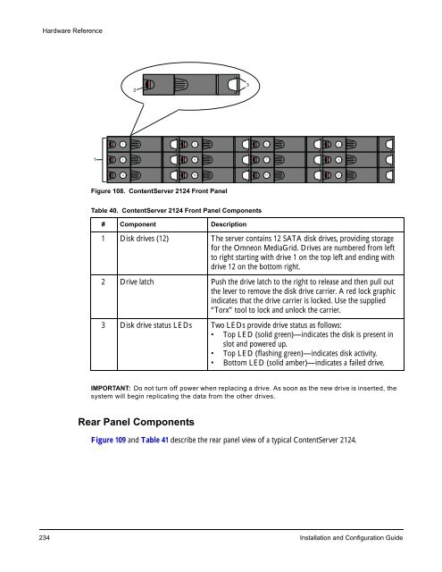
Hardware Reference 1 1 5 9 2 Figure 108. ContentServer 2124 Front Panel Table 40. ContentServer 2124 Front Panel Components # Component Description 1 Disk drives (12) The server contains 12 SATA disk drives, providing storage for the Omneon MediaGrid. Drives are numbered from left to right starting with drive 1 on the top left and ending with drive 12 on the bottom right. 2 Drive latch Push the drive latch to the right to release and then pull out the lever to remove the disk drive carrier. A red lock graphic indicates that the drive carrier is locked. Use the supplied “Torx” tool to lock and unlock the carrier. 3 Disk drive status LEDs Two LEDs provide drive status as follows: • Top LED (solid green)—indicates the disk is present in slot and powered up. • Top LED (flashing green)—indicates disk activity. • Bottom LED (solid amber)—indicates a failed drive. IMPORTANT: Do not turn off power when replacing a drive. As soon as the new drive is inserted, the system will begin replicating the data from the other drives. Rear Panel Components 2 6 10 Figure 109 and Table 41 describe the rear panel view of a typical ContentServer 2124. 234 Installation and Configuration Guide 3 3 7 11 4 8 12
2 1 2 1 3 ID Figure 109. ContentServer 2124 Rear Panel 4 5 S tatus NIC 0 NIC 1 Table 41. ContentServer 2124 Rear Panel Components # Component Description 6 7 8 9 11 10 Hardware Reference 1 Power supplies Dual, redundant power supplies provide power to the system. 2 Power supply status LED Lights to indicate status of the power supply, as follows: • No Color—indicates no AC power to power supply unit. • Green (blinking)—indicates that power supplied to the unit and standby voltages are available. • Green (solid on)—indicates that all power outputs available. • Amber (solid on)—indicates that the power supply has failed; shutdown due to over current; shutdown due to over temperature; indicating a predictive failure. 3 ID LED Blinks on when the unit has been “winked” from the SystemManager application. 4 PS/2 mouse connector Use to connect a mouse to the system. 5 PS/2 keyboard connector Use to connect a keyboard to the system. 6 System status LED Lights to indicate status of the system, as follows: • No Color—indicates that the system not ready; the AC power is off. • Green/Amber (alternate blinking)—indicates the system is not ready; pre-power is on. • Green (solid on)—indicates the system booted and is ready. • Green (blink)—indicates the system degraded. • Amber (blink)—indicates a on-critical or non-fatal alarm. • Amber (solid on)—indicates a critical, non-recoverable error. The system has failed or shut down. Omneon, Now Part of Harmonic 235 13 NIC 3 NIC 2 14 12
- Page 207 and 208: Administrative Procedures Use the f
- Page 209 and 210: Administrative Procedures 1. From t
- Page 211 and 212: To log on to a ContentDirector: 1.
- Page 213 and 214: 3. Type the following two lines at
- Page 215 and 216: Administrative Procedures 1. Attach
- Page 217 and 218: 4. Change directory to /mnt, as sho
- Page 219 and 220: CHAPTER 7 Hardware Reference This c
- Page 221 and 222: Figure 67. Rear View of 1010 Networ
- Page 223 and 224: Power, fault and locator LEDs Conso
- Page 225 and 226: Power and fault LEDs Figure 75. Rea
- Page 227 and 228: Table 8. ContentDirector Indicator
- Page 229 and 230: Drive-status Indicator Pattern Cond
- Page 231 and 232: Indicator Pattern Condition Content
- Page 233 and 234: Off White Blue Red Ethernet Port 0
- Page 235 and 236: Link indicator Port 0 Port 1 Figure
- Page 237 and 238: Yellow Power on White Red Ethernet
- Page 239 and 240: Table 21. Drive-status Indicator Pa
- Page 241 and 242: Power Supply LEDs Figure 93 and Tab
- Page 243 and 244: Table 26. ContentServer 1042 Ethern
- Page 245 and 246: Table 29. ContentServer 1042B Rear
- Page 247 and 248: Figure 99. Rear View of ContentServ
- Page 249 and 250: 1 PWR RST MediaGrid Figure 101. Con
- Page 251 and 252: Table 34. ContentServer 2122 Front
- Page 253 and 254: 2 1 2 1 3 ID Figure 104. ContentSer
- Page 255 and 256: Front Panel Components Front Bezel
- Page 257: Table 39. ContentServer 2124 Front
- Page 261 and 262: ContentServer 3000 Hardware Referen
- Page 263 and 264: Left Control Panel Figure 113. Cont
- Page 265 and 266: Table 46. Disk Drive Status LEDs LE
- Page 267 and 268: Table 47. ContentServer 3000 Rear P
- Page 269 and 270: Figure 117. NVRAM Card LEDs 2 1 3 T
- Page 271 and 272: Figure 119. 10 Gigabit Ethernet Add
- Page 273 and 274: 1 Drive 15 15 OPEN 14 Figure 121. C
- Page 275 and 276: Table 55. ContentStore 3160 Front B
- Page 277 and 278: Table 57. ContentStore 3160 Rear Pa
- Page 279 and 280: CHAPTER 8 Troubleshooting This sect
- Page 281 and 282: Troubleshooting The dhcp-leases fil
- Page 283 and 284: Troubleshooting The two most import
- Page 285 and 286: Troubleshooting points. The number
- Page 287 and 288: Security with Microsoft Domain Cont
- Page 289 and 290: mdsclientn dialog output: Troublesh
- Page 291 and 292: sessions output: *** 1/64 RPC sessi
- Page 293 and 294: APPENDIX A Legacy Hardware Platform
- Page 295 and 296: Figure 127. ContentDirector Hard Dr
- Page 297 and 298: . Figure 129. ContentDirector Power
- Page 299 and 300: Table 65. ContentDirector Indicator
- Page 301 and 302: Drive-status Indicator Pattern Cond
- Page 303 and 304: 1. Link indicator 2. Activity indic
- Page 305 and 306: Figure 139 and Table 72 describe th
- Page 307 and 308: Figure 141. ContentBridge Front Pan
Hardware Reference<br />
1<br />
1<br />
5<br />
9<br />
2<br />
Figure 108. ContentServer 2124 Front Panel<br />
Table 40. ContentServer 2124 Front Panel Components<br />
# Component Description<br />
1 Disk drives (12) The server contains 12 SATA disk drives, providing storage<br />
for the <strong>Omneon</strong> <strong>MediaGrid</strong>. Drives are numbered from left<br />
to right starting with drive 1 on the top left and ending with<br />
drive 12 on the bottom right.<br />
2 Drive latch Push the drive latch to the right to release and then pull out<br />
the lever to remove the disk drive carrier. A red lock graphic<br />
indicates that the drive carrier is locked. Use the supplied<br />
“Torx” tool to lock and unlock the carrier.<br />
3 Disk drive status LEDs Two LEDs provide drive status as follows:<br />
• Top LED (solid green)—indicates the disk is present in<br />
slot and powered up.<br />
• Top LED (flashing green)—indicates disk activity.<br />
• Bottom LED (solid amber)—indicates a failed drive.<br />
IMPORTANT: Do not turn off power when replacing a drive. As soon as the new drive is inserted, the<br />
system will begin replicating the data from the other drives.<br />
Rear Panel Components<br />
2<br />
6<br />
10<br />
Figure 109 and Table 41 describe the rear panel view of a typical ContentServer 2124.<br />
234 Installation and Configuration Guide<br />
3<br />
3<br />
7<br />
11<br />
4<br />
8<br />
12


