About Omneon MediaGrid - Harmonic Inc
About Omneon MediaGrid - Harmonic Inc About Omneon MediaGrid - Harmonic Inc
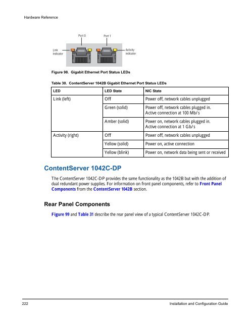
Hardware Reference Link indicator Port 0 Port 1 Figure 98. Gigabit Ethernet Port Status LEDs Table 30. ContentServer 1042B Gigabit Ethernet Port Status LEDs LED LED State NIC State Link (left) Off Power off, network cables unplugged ContentServer 1042C-DP The ContentServer 1042C-DP provides the same functionality as the 1042B but with the addition of dual redundant power supplies. For information on front panel components, refer to Front Panel Components from the ContentServer 1042B section. Rear Panel Components Activity indicator Green (solid) Power off, network cables plugged in. Active connection at 100 Mb/s Amber (solid) Power on, network cables plugged in. Active connection at 1 Gb/s Activity (right) Off Power off, network cables unplugged Yellow (solid) Power on, active connection Yellow (blink) Power on, network data being sent or received Figure 99 and Table 31 describe the rear panel view of a typical ContentServer 1042C-DP. 222 Installation and Configuration Guide
Figure 99. Rear View of ContentServer 1042C-DP Table 31. ContentServer 1042C-DP Rear Panel Descriptions Indicator, Button, or Connector Description ContentServer NIC Indicator Codes Figure 100 and Table 32 provide descriptions of the Gigabit Ethernet Port Status LEDs. Hardware Reference 1. Power Supplies (2) Dual redundant power supplies. For replacement instructions, refer to the Omneon MediaGrid Component Replacement Guide. 2. Power Supply Status LED LEDs to indicate status of the power supply, as follows: • Off—indicates no AC power to power supply unit. • Green (blinking)—indicates unit is powering on • Green (solid on)—indicates that all power outputs available • Red (blinking on)—indicates that the power supply has failed Note that when a power supply has failed, an audible alarm sounds 3.Reset Button Restarts an unresponsive ContentServer. Use only when directed by Omneon Support. Pressing this button during normal operation may cause loss of data 4. Soft Power Button Used to control the motherboard power-on status, independent of the physical power switch on the rear panel of the ContentServer. This may be used to power on the ContentServer if it is still unresponsive after turning on the physical power switch. Use only when directed by Omneon Support. Pressing this button during normal operation may cause loss of data. 5. Wink LED Blinks on when the unit has been “winked” from the SystemManager application. 6. Serial Connector Unused 7. Gigabit Ethernet ports (Left =NIC 0, Right =NIC 1) Use these Gigabit Ethernet ports for system communication and interfacing with selected applications. Refer to Table 32 for a description of each LED state. Omneon, Now Part of Harmonic 223
- Page 195 and 196: Accessing the Omneon MediaGrid •
- Page 197 and 198: Using AFP on a Macintosh Client Fol
- Page 199 and 200: Accessing the Omneon MediaGrid For
- Page 201 and 202: CHAPTER 6 Administrative Procedures
- Page 203 and 204: Table 6. mgcopy Values Values Descr
- Page 205 and 206: Figure 60. Firmware Version Selecti
- Page 207 and 208: Administrative Procedures Use the f
- Page 209 and 210: Administrative Procedures 1. From t
- Page 211 and 212: To log on to a ContentDirector: 1.
- Page 213 and 214: 3. Type the following two lines at
- Page 215 and 216: Administrative Procedures 1. Attach
- Page 217 and 218: 4. Change directory to /mnt, as sho
- Page 219 and 220: CHAPTER 7 Hardware Reference This c
- Page 221 and 222: Figure 67. Rear View of 1010 Networ
- Page 223 and 224: Power, fault and locator LEDs Conso
- Page 225 and 226: Power and fault LEDs Figure 75. Rea
- Page 227 and 228: Table 8. ContentDirector Indicator
- Page 229 and 230: Drive-status Indicator Pattern Cond
- Page 231 and 232: Indicator Pattern Condition Content
- Page 233 and 234: Off White Blue Red Ethernet Port 0
- Page 235 and 236: Link indicator Port 0 Port 1 Figure
- Page 237 and 238: Yellow Power on White Red Ethernet
- Page 239 and 240: Table 21. Drive-status Indicator Pa
- Page 241 and 242: Power Supply LEDs Figure 93 and Tab
- Page 243 and 244: Table 26. ContentServer 1042 Ethern
- Page 245: Table 29. ContentServer 1042B Rear
- Page 249 and 250: 1 PWR RST MediaGrid Figure 101. Con
- Page 251 and 252: Table 34. ContentServer 2122 Front
- Page 253 and 254: 2 1 2 1 3 ID Figure 104. ContentSer
- Page 255 and 256: Front Panel Components Front Bezel
- Page 257 and 258: Table 39. ContentServer 2124 Front
- Page 259 and 260: 2 1 2 1 3 ID Figure 109. ContentSer
- Page 261 and 262: ContentServer 3000 Hardware Referen
- Page 263 and 264: Left Control Panel Figure 113. Cont
- Page 265 and 266: Table 46. Disk Drive Status LEDs LE
- Page 267 and 268: Table 47. ContentServer 3000 Rear P
- Page 269 and 270: Figure 117. NVRAM Card LEDs 2 1 3 T
- Page 271 and 272: Figure 119. 10 Gigabit Ethernet Add
- Page 273 and 274: 1 Drive 15 15 OPEN 14 Figure 121. C
- Page 275 and 276: Table 55. ContentStore 3160 Front B
- Page 277 and 278: Table 57. ContentStore 3160 Rear Pa
- Page 279 and 280: CHAPTER 8 Troubleshooting This sect
- Page 281 and 282: Troubleshooting The dhcp-leases fil
- Page 283 and 284: Troubleshooting The two most import
- Page 285 and 286: Troubleshooting points. The number
- Page 287 and 288: Security with Microsoft Domain Cont
- Page 289 and 290: mdsclientn dialog output: Troublesh
- Page 291 and 292: sessions output: *** 1/64 RPC sessi
- Page 293 and 294: APPENDIX A Legacy Hardware Platform
- Page 295 and 296: Figure 127. ContentDirector Hard Dr
Hardware Reference<br />
Link<br />
indicator<br />
Port 0 Port 1<br />
Figure 98. Gigabit Ethernet Port Status LEDs<br />
Table 30. ContentServer 1042B Gigabit Ethernet Port Status LEDs<br />
LED LED State NIC State<br />
Link (left) Off Power off, network cables unplugged<br />
ContentServer 1042C-DP<br />
The ContentServer 1042C-DP provides the same functionality as the 1042B but with the addition of<br />
dual redundant power supplies. For information on front panel components, refer to Front Panel<br />
Components from the ContentServer 1042B section.<br />
Rear Panel Components<br />
Activity<br />
indicator<br />
Green (solid) Power off, network cables plugged in.<br />
Active connection at 100 Mb/s<br />
Amber (solid) Power on, network cables plugged in.<br />
Active connection at 1 Gb/s<br />
Activity (right) Off Power off, network cables unplugged<br />
Yellow (solid) Power on, active connection<br />
Yellow (blink) Power on, network data being sent or received<br />
Figure 99 and Table 31 describe the rear panel view of a typical ContentServer 1042C-DP.<br />
222 Installation and Configuration Guide


