Positioning System HIWIN - Industrial Technologies
Positioning System HIWIN - Industrial Technologies
Positioning System HIWIN - Industrial Technologies
- No tags were found...

You also want an ePaper? Increase the reach of your titles
YUMPU automatically turns print PDFs into web optimized ePapers that Google loves.
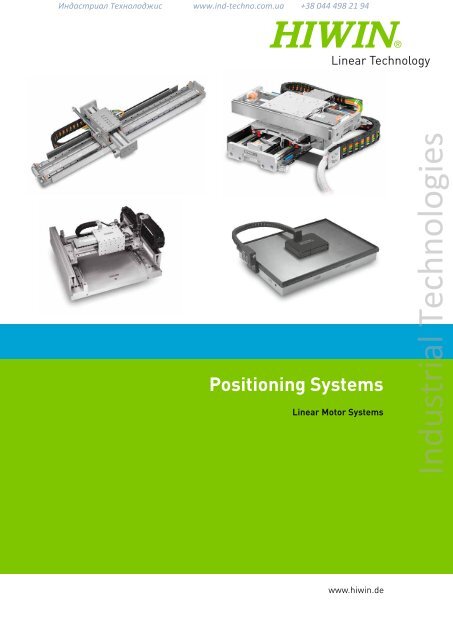
Индастриал Технолоджис www.ind-techno.com.ua +38 044 498 21 94<strong>Positioning</strong> <strong>System</strong>sLinear Motor <strong>System</strong>s<strong>Industrial</strong> <strong>Technologies</strong>www.hiwin.de
Индастриал Технолоджис www.ind-techno.com.ua +38 044 498 21 94<strong>HIWIN</strong> GmbHBrücklesbünd 2D-77654 OffenburgPhone +49 (0) 7 81 9 32 78 - 0Fax +49 (0) 7 81 9 32 78 - 90info@hiwin.dewww.hiwin.de<strong>Industrial</strong> <strong>Technologies</strong>All rights reserved.Complete or partial reproductionis not permitted without our permission.Note:The technical data in this catalog maybe changed without prior notice.
Индастриал Технолоджис www.ind-techno.com.ua +38 044 498 21 94Welcome to <strong>HIWIN</strong><strong>HIWIN</strong> positioning systems facilitate positioning that isaccurate in terms of time and location. These positioningsystems are designed as direct drives and are suitable forinstallation in a horizontal or vertical position. Due to thedirect drive, they are free of backlash, very dynamic andare low maintenance. They can be supplied as a completesolution including a drive amplifier on request.<strong>Industrial</strong> <strong>Technologies</strong>
Индастриал Технолоджис www.ind-techno.com.ua +38 044 498 21 94<strong>Positioning</strong> <strong>System</strong>sMaking linear progress affordable<strong>Industrial</strong> <strong>Technologies</strong>
Индастриал Технолоджис www.ind-techno.com.ua +38 044 498 21 94Table of ContentsIntroduction1. General Information1.1 Glossary 21.2 Typical Parameters 42. Linear Motors2.1 Product overview 62.2 Typical characteristics of Linear Motors 82.3 Scope of delivery 92.4 Drive Amplifier for Linear Motors 102.5 <strong>System</strong> Configuration 112.6 Model Numbers 122.7 LMX1E Linear Motors 152.8 LMX1L-S Linear Motors 222.9 LMX1L-T Linear Motors 362.10 LMV1L Linear Motors 382.11 LMH1L Linear Motors 402.12 X-Y Stages 432.13 Gantry systems 473. Customized <strong>Positioning</strong> <strong>System</strong>s3.1 Examples 484. Planar servo motors and planar motors4.1 LMSP Planar Servo Motors 544.2 Control Card PC14P 584.3 Terminal block PC14B-TB 58<strong>Industrial</strong> <strong>Technologies</strong>1
Индастриал Технолоджис www.ind-techno.com.ua +38 044 498 21 94<strong>Positioning</strong> <strong>System</strong>sCustomized <strong>Positioning</strong> <strong>System</strong>s1.1 GlossaryResolutionThis is the smallest stroke that can be detected by the distance measuringsystem in use. The achievable > increment is usually higher than the resolutiondue to additional factors.AccelerationThis is the speed change per time unit, i.e. acceleration = speed / time or a = v / t.Acceleration timeThis is defined as the time that a drive requires to reach maximum speedfrom standstill.Continuous torque, continuous force(also see Section 1.3, F c )A motor can produce continuous torque or nominal torque (with rotationalmovements) and continuous force or nominal force (with linear movements)in continuous operation (duty cycle = 100 %).Continuous current I c(also see Section 1.3, I c )This is the current supplied over a longer period; the maximum permittedcontinuous current per winding is referred to as the nominal current.The continuous current is characterized by the fact that the dissipationpower only results in motor warming of approximately 90 °C above ambienttemperature.TorqueThis is the dimension which causes a rotation movement in a body and consequentlya vectorial dimension, which can be expressed in the following cross product:M = r x F 1The torque is expressed physically in the unit Nm = kgm²/s².FlatnessThis is a measure for the vertical straightness of a movement on the X axis.A deviation from the absolute levelness is a shift on the Z axis when movingon the X axis.Guide deviationThis is the linear deviation from the stroke axis. It is dependent on straightness(thus the accuracy at the level of the table) and levelness (the accuracy externalto the level of the table).Back EMF constant(also see Chapter 1.3, K u )This is the relation between the back EMF voltage (rms) and the motor rotational speedor speed (rpm or m/s). Back EMF is the electromagnetic force that is created duringthe movement of windings in the magnetic field of permanent magnets, e.g.in a servo motor.Accuracy (Absolute accuracy)This, or the actual inaccuracy, corresponds to the deviation between a targeted positionand the actual position. The accuracy along an axis is defined as the differencebetween the actual and target positions after all other linear deviations that can beeliminated have been excluded. Such systematic and linear deviations are the result,for example, of cosine errors, angle deviations, shaft pitch errors, thermal expansionetc. Accuracy is calculated for all relevant target positions of an application using tothe following formula:Maximum of all sums of systematic target-actual deviations + 2 sigma(standard deviation). Accuracy must not be confused with > repeatability.StraightnessThis is a measure for the horizontal straightness of a movement on the X axis. A deviationfrom the absolute straightness is a shift on the Y axis when moving on the X axis.Force, torqueForce (in linear movements) or torque (in rotational movements) is givenfor defined conditions, e.g. as continuous force or torque at:25 °C ambient temperature110 °C winding temperature100 % operating time for linear motors and torque motors50 % operating time for rotary tablesor as peak force or peak torque.<strong>Industrial</strong> <strong>Technologies</strong>EccentricityThis is the deviation of the center point of rotation of rotary tables from its positionduring rotation. It is created by centering and bearing tolerances.2
Индастриал Технолоджис www.ind-techno.com.ua +38 044 498 21 94Force constant K f(also see Chapter 1.3, K f )This is the winding-specific parameter used to calculate the resultant forceas F = I × K f by multiplication with the input current.Attraction force F aThis force is created between the primary and secondary parts of iron-core linearmotors, by biasing voltage of the drive system, which must then be taken upby the guide.Motor constant K m(also see Chapter 1.3, K m )This designates the ratio of generated power and dissipation powerand consequently is a measure for efficiency of a motor.IncrementThis, or the smallest increment, is the minimum stroke that a linear drive cantravel repeatedly. It is determined by the >resolution of the linear drive plus theincrement of the motor and all errors in the drive line (reverse play, winding etc.)Peak torque, peak force F pThe peak torque (for rotational movements) or the peak force (for linear movements)is the maximum force that a motor can generate for approximately one second.With <strong>HIWIN</strong>, it is at the end of the linear modulation range at peak current I pand is significant especially during acceleration and braking.Peak current I p(also see Chapter 1.3, I p )It is used for short-term generation of peak power. <strong>HIWIN</strong> defines peak currentas follows: Iron-core motors and coreless motors have three times the permittedcontinuous current as Ip. The maximum permitted length of peak current isone second. Thereafter, the motor must cool down to the nominal temperaturebefore peak current can be supplied again.Multi-IndexOne incremental track is arranged on the scale. The sensor in the encoder headreads out 3 signals: incremental tracks A and B and Z-track for the internalreference signal. Each reference mark on the scale creates a reference signal(multi-index). An external reference switch is essential to trigger the referencesignal. After operating the external reference switch the next reference mark onthe magnetic scale defines the reference signal.Single-IndexThe magnetic scale is split in two tracks, incremental track and reference-track.Depending on the specification one or several reference marks are on the index rackare arranged on scale.In the sensor are two sensor heads integrated. One for the tracks A and B and one forthe reference track. Single-index-scales are always custom-made.StiffnessThis corresponds to the mechanical deformation resistance that a component or assemblyhas against a static external load in a steady-state, static state (static stiffness)or the elastic deformation resistance that a component or assembly has againsta dynamic force working from the outside (dynamic stiffness).WobblingThis is the angle deviation in the rotation axis from rotary tables during rotationalmovements, i.e. tipping of the surface of a rotary table. The causes are mainlytolerances in the bearing.Winding resistance R 25This is the winding-specific dimension that is produced by the winding resistanceat 25 °C winding temperature . At 80 °C winding temperature, the winding resistanceincreases to approximately 1.2 × R 25.Winding temperature T max(also see Chapter 1.3, T)This is the permitted winding temperature. The actual motor temperature is dependenton the installation, cooling and operating conditions and consequently can only bedetermined in an actual case and cannot be calculated.RepeatabilityThis may not be confused with absolute preciseness. A linear axis can have slightpreciseness, but high repeatability. The uni-directional repeatability is measuredwhen there is movement to a target position from an appropriately large stroke inthe same direction several times; doing this the other way around does not work.In the measurement of bi-direction repeatability, there is movement to a targetposition is driven from different movement directions; doing this the other wayaround does not work.<strong>Industrial</strong> <strong>Technologies</strong>3
Индастриал Технолоджис www.ind-techno.com.ua +38 044 498 21 94<strong>Positioning</strong> <strong>System</strong>sCustomized <strong>Positioning</strong> <strong>System</strong>s1.2 Typical Dimensions1.2.1 Winding-independent dimensions1.2.2 Winding-dependent dimensionsF aF cF pK mP vP vpP cTRelative constant force between primary and secondary part (magneticbasis) that must be handled by a mechanical guide.Motor power, which is available in nominal operation as continuous forceand which results in warming to 90 °C above ambient temperature.Motor power that can be generated for a short time, which is reachedat I p at the end of the linear modulation range and resultsin substantial heating up when there is no cooling.Motor constant, which expresses the ratio of generated power and dissipationpower and consequently the degree of effectiveness.The heat output created in the motor winding, which results in a time-dependenttemperature rise dependent on the operating mode (current) and the ambientconditions (cooling) In the upper control P v is especially high in the upper modulationrange (at I p ) due to the quadratic dependency of current, while only relatively slightwarming occurs in the range of the nominal current. P v is calculated using themotor constant K m for a movement section with the required force F: P v = F / K m2Peak dissipation power at I pDissipation power at I cPermissible winding temperature, which is recorded by sensorsor thermal circuit breakers; the created motor surface temperatureis dependent onthe actual installation conditions (table size)the heat dissipation conditions (cooling)the operating mode and consequently the mean performance entrycan only be determined if these variables are known.I cI pK fK uFor generating the current connected for continuous force.For short-term generation of the peak force of connected peak current.Winding dimension, which produces the created force with the current:F = I × K fWinding dimension, which results dependent on the speedcreated in the motor terminalsingenerator operation: U g = K u × vR 25 Winding resistance at 25 °C; this increasesto approx. 1.2 times the value at 80 °C.<strong>Industrial</strong> <strong>Technologies</strong>4
Индастриал Технолоджис www.ind-techno.com.ua +38 044 498 21 942. Linear Motors2.1 Product overview 62.2 Typical characteristics of Linear Motors 82.3 Scope of delivery 92.4 Drive Amplifier for Linear Motors 102.5 <strong>System</strong> Configuration 112.6 Model Numbers 122.7 LMX1E Linear Motors 152.8 LMX1L-S Linear Motors 222.9 LMX1L-T Linear Motors 362.10 LMV1L Linear Motors 382.11 LMH1L Linear Motors 402.12 X-Y Stages 432.13 Gantry systems 472.7 2.8 2.92.10 2.11 2.12<strong>Industrial</strong> <strong>Technologies</strong>2.135
Индастриал Технолоджис www.ind-techno.com.ua +38 044 498 21 94<strong>Positioning</strong> <strong>System</strong>sLinear motor axis2. Linear Motor Axe2.1 Product OverviewLMX1E Page 15Complete axis with coreless motor, type LMCIdeal for applications with a high degree of synchronization requirementsOptional enclosure by metal cover or bellow coverAlso for use as a cross tableStroke is measured via optical distance measuring system incrementallyor absolutelyTotal length up to 4000 mmLMX1L-S Page 22Complete axis with iron-core motor, type LMSIdeal for applications with high continuous power requirementsOptional enclosure by metal cover or bellow coverAlso for use as a cross tableStroke is measured via optical or magnetic distance measuring systemincrementally or absolutely depending on requirementsTotal length up to 4000 mmLMX1L-T Page 36Complete axis with iron-core motor, type LMTSandwich design makes high power density possible without static loadof the guides by attraction forcesOptional enclosure by metal cover or bellow coverStroke is measured via optical or magnetic distance measuring systemincremental or absolutely depending on requirementsTotal length up to 4000 mm<strong>Industrial</strong> <strong>Technologies</strong>LMV1L Page 38Complete axis with iron-core motor, type LMSUse as a vertical axisFor applications with gripper connectionStroke is measured via optical or magnetic distance measuring systemincrementally or absolutely depending on requirements6
Индастриал Технолоджис www.ind-techno.com.ua +38 044 498 21 94LMH1L Page 40Complete axis with iron-core motor, type LMSStroke is measured incrementally via magnetic encodersIdeal for applications with long stroke (up to 30 m)Enclosure possibleCross tables Page 43Combination of axis from the LMX seriesWith coreless or iron-core motorsGantry systems Page 47Standardized gantry systems with coreless motorsor iron-core motors<strong>Industrial</strong> <strong>Technologies</strong>7
Индастриал Технолоджис www.ind-techno.com.ua +38 044 498 21 94<strong>Positioning</strong> <strong>System</strong>sLinear motor axis2.2 Typical Properties of Linear Motor Axis<strong>HIWIN</strong> linear motor axis are directly driven axis with linear motors, which aredesigned as a plug and play solution. Standardized energy chains and customizedcable guides are available as an option. These are suspended complete axis withdistance measuring system, guides, limit switches and optionally with coversas protection against environmental influences. An arresting brake canbe built in optionally.Several forcers per axisCan be combined with other axisNo realignmentLow maintenanceLong operating life and high reliabilityExtremely precise and fast positioningSmooth runningHigh stroke speedCompact design, consequently small space requirementsOptimum accuracyDue to the direct drive, the linear axis are free from backlash, very dynamic,low maintenance and can also be equipped with several forcers. The linearaxis are supplied as a complete solution including drive amplifier on request.Customers can select the drive manufacturer of their wish. We supplythe required electronic parameters for adaptation of the linear motors.<strong>Industrial</strong> <strong>Technologies</strong>8
Индастриал Технолоджис www.ind-techno.com.ua +38 044 498 21 942.3 Scope of deliveryDrive amplifier:(see page 10)The suitable drive amplifier is selectedaccording to the customer’s applicationsand parameterized in line with the linearmotor axis to be supplied. This ensures thedynamic running properties of the respectivelinear motor axis.Possible Interfaces:ProfibusCANopenSercosSerial via RS23210 V analogPulse/directionOhters on requestPositive (+) movement directionThe movement direction is defined via the positionof the reference switch. As a standard, it ison the same side as the limit switch plug (1).+Richtung(1)Power feedStandard type or designed customer-specificand adapted to local conditionsDifferent dimensions for additional cables possibleDifferent screw-on positions possibleThree cables:Output cableEncoder cableLimit switch cableStandard lengths each L = 2 m, optional to L max = 10 mfrom the end of the cable chain possible; the cables arecertified according to CE and UL regulations.<strong>Industrial</strong> <strong>Technologies</strong>Standard linear motor axisDifferent types: see pages 15 – 489
Индастриал Технолоджис www.ind-techno.com.ua +38 044 498 21 94<strong>Positioning</strong> <strong>System</strong>sLinear motor axis2.4 Drive Amplifier for Linear Motor Axis<strong>HIWIN</strong> selects the drive amplifier suitable for the respective application or according to customer request.Our system partners for drive amplifiers include:<strong>Industrial</strong> <strong>Technologies</strong>ESR Pollmeier GmbHwww.esr-pollmeier.de10
Индастриал Технолоджис www.ind-techno.com.ua +38 044 498 21 942.5 <strong>System</strong> Configuration1 Fixing of the power feed2 Motor plug3 Distance measuring system plug (encoder)4 Power feed5 optional: Distance plate for cover6 Forcer plate7 Cam switch8 Forcer9 Linear guideway block10 Distance measuring system MAGIC-PG11 Rail with magnet scale for MAGIC-PG12 Rail13 Stator14 Stopping buffer15 optional: Distance plate for cover16 End cap17 Plug for limit- and reference switch18 Limit- and reference switch incl. fixing bracket19 Fixing of the power feed20 Basic profileGeneral Specifications for Linear Motor AxisName Motor type v max[m/s]a max[m/s 2 ]Total lengthL max[mm]Repeatability1) Values apply only with an appropriate specified base frame.2) Values apply to the optical incremental distance measuring system with 40 µm periods of the sin/cos signal.3) Values apply to the <strong>HIWIN</strong>-MAGIC optical incremental distance measuring system with a sinus/cosinus signal (see catalogue Direct Components).4) If bellow covers are used, the maximum acceleration could be restricted.[mm]Accuracy 1)[mm/300 mm]Straightness 1)[mm/300 mm]Flatness[mm/300 mm]LMX1E- ... LMC 5 100 4) 4000 ± 0.001 2) ± 0.005 2) ± 0.01 ± 0.01 15LMX1L-S ... LMS 4 50 4) 4000 ± 0.001 2) ± 0.005 2) ± 0.01 ± 0.01 22LMX1L-T ... LMT 4 50 4000 ± 0.001 2) ± 0.005 2) ± 0.01 ± 0.01 36LMV1L- ... LMS 1.8 30 600 ± 0.001 2) ± 0.005 2) ± 0.01 ± 0.01 38LMH1L- ... LMS 4 50 30000 ± 0.02 3) ± 0.05 3) ± 0.03 ± 0.03 40<strong>Industrial</strong> <strong>Technologies</strong>PageThe distance measuring system is optical or magnetic, depending on the linear axis type or the customer’s requirement. As standard, sin/cos 1 V ppis processed as an output signal; a TTL signal is also possible.The maximum operating voltage depends on the linear motor type in use. For motor types LMS and LMT (iron-core motors), the maximum permissibleoperating voltage is AC 530 V. For the LMC motor series (coreless motors), the maximum operating voltage is AC 240 V.11
Индастриал Технолоджис www.ind-techno.com.ua +38 044 498 21 94<strong>Positioning</strong> <strong>System</strong>sLinear motor axis2.6 Model Numbers for Linear Motor Axis2.6.1 Model Numbers for Single Linear Motor AxisLinear motor axisAxis typeX: Horizontal axisV: Vertical axisH: PortalaxisLM X 1 L S23 1 0872 A 1 0 0 0 XXXNumber of axis1: single axisGuide railsL: Standard for iron-core motors (LMS)E: Standard for coreless motors (LMC)F: Flat design for coreless motors,max. length 1 mC: CustomisedMotor typeSxx: iron-core linear motorsCxx: coreless linear motorsT37x: iron-core linear motorin sandwich designNumber of forcers1) For LMH-axis distance measuring system “D” is obligatoryStroke [mm]Cover0: none (standard)A: Metal coverB: Bellow coverLimit switch0: none1: inductive, PNP (standard)2: optical, NPNPower feed size0: Standard for LMC-Axis1: Standard for LMS-Axis2: Standard for LMH-AxisC: CustomisedPower feed alignment0: none (standard)1: for horizontal alignment2: for vertical alignmentC: CustomisedDistance measuring system 1)A: optical, period 40 µm, analog 1V pp sin/cosB: optical, period 20 µm, analog 1V pp sin/cosC: <strong>HIWIN</strong>-MAGIC: magnetic, period 1 mm, 1 V pp sin/cosD: <strong>HIWIN</strong>-MAGIC-PG: magnetic, period 1 mm, 1 V pp sin/cos Magneticway integrated in the guide rails (standard)E: optical, absolute, enclosed, with ENDAT interfaceF: optical, incremental, 4 µm periods, glass scaleG: optical, digital TTL, resolution 1 µmAll encoders with individual reference signal at the start of the axisJob number of drawingSeveral forcers, Hall sensor,mass compensation,brake, special fixing holes<strong>Industrial</strong> <strong>Technologies</strong>12
Индастриал Технолоджис www.ind-techno.com.ua +38 044 498 21 942.6.2 Model numbers forr Cross TablesLinear motor axisAxis typeX: Horizontal axisLM X 2 L S23 S27 232 280 A 1 XXXNumber of axis2: two axisGuide railsL: Standard for iron-core motorsE: Standard for coreless motorsF: Flat design for coreless motors,max. length 1 mC: CustomisedMotor type of upper axisSxx: iron-core linear motorsCxx: coreless linear motorsMotor type of lower axisSxx: iron-core linear motorsCxx: coreless linear motorsStroke of upper axis [mm]Limit switch0: none1: inductive, PNP (standard)2: optical, NPNDistance measuring systemA: optical, period 40 µm, analog 1V pp sin/cosB: optical, period 20 µm, analog 1V pp sin/cosC: <strong>HIWIN</strong>-MAGIC: magnetic, period 1 mm, 1 V pp sin/cosD: <strong>HIWIN</strong>-MAGIC-PG: magnetic, period 1 mm, 1 V pp sin/cos Magneticway integrated in the guide rails (standard)E: optical, absolute, enclosed, with ENDAT interfaceF: optical, incremental, 4 µm periods, glass scaleG: optical, digital TTL, resolution 1 µmAll encoders with individual reference signal at the start of the axisStroke of lower axis [mm]Job number of drawingSeveral forcers, Hall sensor, mass compensation,brake, special fixing holes<strong>Industrial</strong> <strong>Technologies</strong>13
Индастриал Технолоджис www.ind-techno.com.ua +38 044 498 21 94<strong>Positioning</strong> <strong>System</strong>sLinear motor axis2.6.3 Model Numbers for Gantry <strong>System</strong>sLinear motor axisAxis typeG: Gantry systemLM G 2 A S13 S27 300 400 A 2 XXXNumber of axis2: two axisGuide railsA: Type A (standard)C: CustomisedMotor type of upper axisSxx: iron-core linear motorsCxx: coreless linear motorsMotor type of lower axisSxx: iron-core linear motorsCxx: coreless linear motorsStroke of upper axis [mm]Limit switch0: none1: inductive, PNP (standard)2: optical, NPNDistance measuring systemA: optical, period 40 µm, analog 1V pp sin/cosB: optical, period 20 µm, analog 1V pp sin/cosC: <strong>HIWIN</strong>-MAGIC: magnetic, period 1 mm, 1 V pp sin/cosD: <strong>HIWIN</strong>-MAGIC-PG: magnetic, period 1 mm, 1 V pp sin/cos Magneticway integrated in the guide rails (standard)E: optical, absolute, enclosed, with ENDAT interfaceF: optical, incremental, 4 µm periods, glass scaleG: optical, digital TTL, resolution 1 µmAll encoders with individual reference signal at the start of the axisStroke of lower axis [mm]Job number of drawingSeveral forcers, Hall sensor, mass compensation,brake, special fixing holes<strong>Industrial</strong> <strong>Technologies</strong>14
Индастриал Технолоджис www.ind-techno.com.ua +38 044 498 21 942.7 LMX1E Linear Motor AxisLMX1E linear motor axis are equipped with a coreless motor and are well suitedfor applications with a high degree of synchronous operational requirements.They can also be used in cross tables. They are distinguished by their very flatdesign. The stroke is measured incrementally or absolutely via optical encoders.The LMX1E linear motor axis have very high dynamics and are available in overalllengths up to 4,000 mm.Max. acceleration 100 m/s 2Max. speed 5 m/sUp to 4,000 mm longDimension of power feedPower feedalignmentSpecifications for LMX1E Linear Motor AxisName(Model number)xxxx = Stroke [mm]C[mm]D[mm]InternaldimensionB i × H i [mm]Horizontal 97 170 50 × 21Vertical 79 170 50 × 21Motor typeF c[N]F p[N]BMass ofglider[kg]Power feed horizontalLength ofglider[mm]v max[m/s]a max[m/s²]Power feed verticalDimension A[mm]Dimension BLMX1E-CB5-1-xxxx-A100 LMC B5 90 270 2 178 5 100 178 80LMX1E-CB6-1-xxxx-A100 LMC B6 110 330 3 208 5 100 178 80LMX1E-CB8-1-xxxx-A100 LMC B8 145 435 4.2 272 5 100 178 80LMX1E-CB5-1-xxxx-A1A0 LMC B5 90 270 2.3 178 5 100 178 92/101*LMX1E-CB6-1-xxxx-A1A0 LMC B6 110 330 3.3 208 5 100 178 92/101*LMX1E-CB8-1-xxxx-A1A0 LMC B8 145 435 4.5 272 5 100 178 92/101*AHiCCBiDDCBiB[mm]<strong>Industrial</strong> <strong>Technologies</strong>HiANotes:F c = Continuous power, 100 % operating time (ED) at 80 °C winding temperatureF p = Peak force (1 s)Electrical parameters for linear motors:* See Dimensional Tables on pages 16 – 2115
Индастриал Технолоджис www.ind-techno.com.ua +38 044 498 21 94<strong>Positioning</strong> <strong>System</strong>sLinear motor axis2.7.1 LMX1E without CoverDimensions and mass of the LMX1E-CB5 axis without coverAll values in mm<strong>Industrial</strong> <strong>Technologies</strong>Stroke [mm] 144 272 400 528 656 784 912 1040 1296 1552 1808Total length L [mm] 450 578 706 834 962 1090 1218 1346 1602 1858 2114Mass [kg] 19 22.5 26 30 33 36.5 40.5 44 51 58.5 6616
Индастриал Технолоджис www.ind-techno.com.ua +38 044 498 21 94Dimensions and Mass of the LMX1E-CB6 Axis without CoverAll values in mm<strong>Industrial</strong> <strong>Technologies</strong>Stroke [mm] 112 240 368 496 624 752 880 1008 1264 1520 1776Total length L [mm] 450 578 706 834 962 1090 1218 1346 1602 1858 2114Mass [kg] 19.3 23 26.6 30.2 33.9 37.5 41.2 44.8 52.1 59.4 66.617
Индастриал Технолоджис www.ind-techno.com.ua +38 044 498 21 94<strong>Positioning</strong> <strong>System</strong>sLinear motor axisDimensions and Mass of the LMX1E-CB8 Axis without CoverAll values in mmh = H – 80<strong>Industrial</strong> <strong>Technologies</strong>Stroke [mm] 176 304 432 560 688 816 944 1200 1456 1712Total length L [mm] 578 706 834 962 1090 1218 1346 1602 1858 2114Mass [kg] 24.5 28.1 31.7 35.4 39 42.7 46.3 53.6 60.8 68.118
Индастриал Технолоджис www.ind-techno.com.ua +38 044 498 21 942.7.2 LMX1E with coverDimensions and Mass of the LMX1E-CB5 Axis with CoverAll values in mmh = H – 80L 1 = Total length with metal cover [mm]L 2 = Total length with bellow cover [mm]<strong>Industrial</strong> <strong>Technologies</strong>Stroke [mm] 144 272 400 528 656 784 912 1040 1296 1552 1808Total length L 1 [mm] 450 578 706 834 962 1090 1218 1346 1602 1858 2114Total length L 2 [mm] 458 660 860 1060 1259 1460 1660 1859 2260 2659 3060H [mm] 92 92 92 92 92 92 92 92 101 101 101Mass [kg] 20.3 24.3 28 32 36 40 44 48 56 64 71.719
Индастриал Технолоджис www.ind-techno.com.ua +38 044 498 21 94<strong>Positioning</strong> <strong>System</strong>sLinear motor axisDimensions and Mass of the LMX1E-CB6 Axis with CoverAll values in mmh = H – 80L 1 = Total length with metal cover [mm]L 2 = Total length with bellow cover [mm]<strong>Industrial</strong> <strong>Technologies</strong>Stroke [mm] 112 240 368 496 624 752 880 1008 1264 1520 1776Total length L 1 [mm] 450 578 706 834 962 1090 1218 1346 1602 1858 2114Total length L 2 [mm] 442 642 841 1041 1242 1442 1641 1842 2241 2642 3041H [mm] 92 92 92 92 92 92 92 92 101 101 101Mass [kg] 21 25 28.9 32.8 36.8 40.7 44.7 48.7 56.6 64.5 72.420
Индастриал Технолоджис www.ind-techno.com.ua +38 044 498 21 94Dimensions and Mass of the LMX1E-CB8 Axis with CoverAll values in mmh = H – 80L 1 = Total length with metal cover [mm]L 2 = Total length with bellow cover [mm]<strong>Industrial</strong> <strong>Technologies</strong>Verfahrweg [mm] 176 304 432 560 688 816 944 1200 1456 1712Gesamtlänge L 1 [mm] 578 706 834 962 1090 1218 1346 1602 1858 2114Gesamtlänge L 2 [mm] 606 806 1005 1205 1406 1605 1805 2206 2606 3005H [mm] 92 92 92 92 92 92 92 101 101 101Gewicht [kg] 26.4 30.4 34.3 38.3 42.2 46.2 50.2 58 66 7421
Индастриал Технолоджис www.ind-techno.com.ua +38 044 498 21 94<strong>Positioning</strong> <strong>System</strong>sLinear motor axis2.8 LMX1L-S Linear Motor AxisLMX1L linear motor axis are equipped with an iron-core motor, which providessubstantial continuous force. They can also be used in cross tables. The stroke ismeasured via the optical or magnetic distance measuring systems incrementallyor absolutely. The LMX1L-S linear motor axis have a very compact designand are available in overall lengths up to 4,000 mm.Max. acceleration 50 m/s 2Max. speed 4 m/sUp to 4,000 mm longDimension of power feedPower feedalignmentC[mm]D[mm]InternaldimensionB i × H i [mm]Horizontal 115 223 68 × 21Vertical 89 222 68 × 21Name(Model number)xxxx = stroke [mm]Motor typeF c[N]F p[N]Mass ofGlider[kg]BAPower feed horizontalLength ofglider[mm]Hiv max[m/s]CCBia max[m/s 2 ]DDDimension A[mm]CBBiPower feed verticalHiDimension BLMX1L-S23-1-xxxx-D100 LMS 23 220 600 7.5 200 4 50 178 90LMX1L-S27-1-xxxx-D100 LMS 27 340 900 9.5 280 4 50 178 90LMX1L-S37-1-xxxx-D100 LMS 37 475 1250 12 280 3.5* 50 202 95LMX1L-S37L-1-xxxx-D100 LMS 37L 475 1250 12 280 4 50 202 95LMX1L-S47-1-xxxx-D100 LMS 47 650 1700 18 280 2.5* 50 232 95LMX1L-S47L-1-xxxx-D100 LMS 47L 650 1700 18 280 4 50 232 95LMX1L-S57-1-xxxx-D100 LMS 57 780 2000 22 280 2* 50 252 100LMX1L-S57L-1-xxxx-D100 LMS 57L 780 2000 22 280 4 50 252 100LMX1L-S67-1-xxxx-D100 LMS 67 950 2500 26 280 2* 50 272 100LMX1L-S67L-1-xxxx-D100 LMS 67L 950 2500 26 280 4 50 272 100LMX1L-S23-1-xxxx-D1A0 LMS 23 220 600 7.8 200 4 50 178 102/111LMX1L-S27-1-xxxx-D1A0 LMS 27 340 900 9.9 280 4 50 178 102/111LMX1L-S37-1-xxxx-D1A0 LMS 37 475 1250 12.5 280 3.5* 50 202 107/116LMX1L-S37L-1-xxxx-D1A0 LMS 37L 475 1250 12.5 280 4 50 202 107/116LMX1L-S47-1-xxxx-D1A0 LMS 47 650 1700 18.8 280 2.5* 50 232 107/116LMX1L-S47L-1-xxxx-D1A0 LMS 47L 650 1700 18.8 280 4 50 232 107/116LMX1L-S57-1-xxxx-D1A0 LMS 57 780 2000 23 280 2* 50 252 112/121LMX1L-S57L-1-xxxx-D1A0 LMS 57L 780 2000 23 280 4 50 252 112/121LMX1L-S67-1-xxxx-D1A0 LMS 67 950 2500 27 280 2* 50 272 112/121LMX1L-S67L-1-xxxx-D1A0 LMS 67L 950 2500 27 280 4 50 272 112/121[mm]<strong>Industrial</strong> <strong>Technologies</strong>ANotes:F c = Continuous power, 100 % operating time (ED), at 80 °C winding temperatureF p = Peak force (1 s)Electrical parameters of LMS linear motors: see catalogue Direct Components* Limited by back-EMF of the motor winding22
Индастриал Технолоджис www.ind-techno.com.ua +38 044 498 21 942.8.1 LMX1L-S linear motor axis without coverDimensions and Mass of the LMX1L-S23 Linear Axis without CoverAll values in mm<strong>Industrial</strong> <strong>Technologies</strong>Stroke [mm] 104 232 360 488 616 744 872 1000 1256 1512 1768 2024Total length L [mm] 450 578 706 834 962 1090 1218 1346 1602 1858 2114 2370Mass [kg] 21.0 23.5 27.0 31.0 34.0 37.0 40.0 43.0 50.0 56.0 62.0 68.023
Индастриал Технолоджис www.ind-techno.com.ua +38 044 498 21 94<strong>Positioning</strong> <strong>System</strong>sLinear motor axisDimensions and Mass of the LMX1L-S27 Linear Axis without CoverAll values in mm<strong>Industrial</strong> <strong>Technologies</strong>Stroke [mm] 152 280 408 536 664 792 920 1176 1432 1688 1944 2200Total length L [mm] 578 706 834 962 1090 1218 1346 1602 1858 2114 2370 2626Mass [kg] 27.0 30.0 33.5 37.0 40.0 43.5 46.5 52.0 58.0 64.0 70.0 76.024
Индастриал Технолоджис www.ind-techno.com.ua +38 044 498 21 94Dimensions and Mass of the LMX1L-S37 und LMX1L-S37L Linear Axis without CoverAll values in mm<strong>Industrial</strong> <strong>Technologies</strong>Stroke [mm] 152 280 408 536 664 792 920 1176 1432 1688 1944 2200Total length L [mm] 578 706 834 962 1090 1218 1346 1602 1858 2114 2370 2626Mass [kg] 33 36 40 43 47 50 54 62 70 78 86 9425
Индастриал Технолоджис www.ind-techno.com.ua +38 044 498 21 94<strong>Positioning</strong> <strong>System</strong>sLinear motor axisDimensions and Mass of the LMX1L-S47 und LMX1L-S47L Linear Axis without CoverAll values in mm<strong>Industrial</strong> <strong>Technologies</strong>Stroke [mm] 152 280 408 536 664 792 920 1176 1432 1688 1944 2200Total length L [mm] 578 706 834 962 1090 1218 1346 1602 1858 2114 2370 2626Mass [kg] 38 41 46 50 55 58 63 71 80 88 96 10526
Индастриал Технолоджис www.ind-techno.com.ua +38 044 498 21 94Dimensions and Mass of the LMX1L-S57 und LMX1L-S57L Linear Axis without CoverAll values in mm<strong>Industrial</strong> <strong>Technologies</strong>Stroke [mm] 152 280 408 536 664 792 920 1176 1432 1688 1944 2200Total length L [mm] 578 706 834 962 1090 1218 1346 1602 1858 2114 2370 2626Mass [kg] 47 51 57 63 69 73 80 90 100 110 120 13027
Индастриал Технолоджис www.ind-techno.com.ua +38 044 498 21 94<strong>Positioning</strong> <strong>System</strong>sLinear motor axisDimensions and Mass of the LMX1L-S67 und LMX1L-S67L Linear Axis without CoverAll values in mm<strong>Industrial</strong> <strong>Technologies</strong>Stroke [mm] 152 280 408 536 664 792 920 1176 1432 1688 1944 2200Total length L [mm] 578 706 834 962 1090 1218 1346 1602 1858 2114 2370 2626Mass [kg] 50 55 61 68 74 78 86 97 107 118 129 14028
Индастриал Технолоджис www.ind-techno.com.ua +38 044 498 21 942.8.2 LMX1L-S linear motor axis with coverDimensions and Mass of the LMX1L-S23 Linear Motor Axis with CoverAll values in mmh = H – 90L 1 = Total length with metal cover [mm]L 2 = Total length with bellow cover [mm]<strong>Industrial</strong> <strong>Technologies</strong>Stroke [mm] 104 232 360 488 616 744 872 1000 1256 1512 1768 2024Total length L 1 [mm] 450 578 706 834 962 1090 1218 1346 1602 1858 2114 2370Total length L 2 [mm] 421 621 821 1021 1222 1421 1621 1821 2221 2622 3021 3421H [mm] 102 102 102 102 102 102 102 102 111 111 111 111Mass [kg] 23.0 26.0 29.5 34.0 37.0 40.0 43.5 46.5 54.0 60.5 67.0 74.029
Индастриал Технолоджис www.ind-techno.com.ua +38 044 498 21 94<strong>Positioning</strong> <strong>System</strong>sLinear motor axisDimensions and Mass of the LMX1L-S27 Linear Motor Axis with CoverAll values in mmh = H – 90L 1 = Total length with metal cover [mm]L 2 = Total length with bellow cover [mm]<strong>Industrial</strong> <strong>Technologies</strong>Stroke [mm] 152 280 408 536 664 792 920 1176 1432 1688 1944 2200Total length L 1 [mm] 578 706 834 962 1090 1218 1346 1602 1858 2114 2370 2626Total length L 2 [mm] 576 775 976 1176 1376 1576 1776 2177 2576 2976 3376 3776H [mm] 102 102 102 102 102 102 102 111 111 111 111 111Mass [kg] 29.5 32.5 36.0 40.0 43.0 47.0 50.0 56.0 62.5 69.0 75.5 82.030
Индастриал Технолоджис www.ind-techno.com.ua +38 044 498 21 94Dimensions and Mass of the LMX1L-S37 and LMX1L-S37L Linear Motor Axis with CoverAll values in mmh = H – 95L 1 = Total length with metal cover [mm]L 2 = Total length with bellow cover [mm]<strong>Industrial</strong> <strong>Technologies</strong>Stroke [mm] 152 280 408 536 664 792 920 1176 1432 1688 1944 2200Total length L 1 [mm] 578 706 834 962 1090 1218 1346 1602 1858 2114 2370 2626Total length L 2 [mm] 576 775 976 1176 1376 1576 1776 2177 2576 2976 3376 3776H [mm] 107 107 107 107 107 107 107 116 116 116 116 116Mass [kg] 36 40 44 47 51 55 59 68 76 85 94 10331
Индастриал Технолоджис www.ind-techno.com.ua +38 044 498 21 94<strong>Positioning</strong> <strong>System</strong>sLinear motor axisDimensions and Mass of the LMX1L-S47 und LMX1L-S47L Linear Motor Axis with CoverAll values in mmh = H – 95L 1 = Total length with metal cover [mm]L 2 = Total length with bellow cover [mm]<strong>Industrial</strong> <strong>Technologies</strong>Stroke [mm] 152 280 408 536 664 792 920 1176 1432 1688 1944 2200Total length L 1 [mm] 578 706 834 962 1090 1218 1346 1602 1858 2114 2370 2626Total length L 2 [mm] 576 775 976 1176 1376 1576 1776 2177 2576 2976 3376 3776H [mm] 107 107 107 107 107 107 107 116 116 116 116 116Mass [kg] 42 45 50 55 60 63 69 78 87 96 105 11432
Индастриал Технолоджис www.ind-techno.com.ua +38 044 498 21 94Dimensions and Mass of the LMX1L-S57 und LMX1L-S57L Linear Motor Axis with CoverAll values in mmh = H – 100L 1 = Total length with metal cover [mm]L 2 = Total length with bellow cover [mm]<strong>Industrial</strong> <strong>Technologies</strong>Stroke [mm] 152 280 408 536 664 792 920 1176 1432 1688 1944 2200Total length L 1 [mm] 578 706 834 962 1090 1218 1346 1602 1858 2114 2370 2626Total length L 2 [mm] 576 775 976 1176 1376 1576 1776 2177 2576 2976 3376 3776H [mm] 112 112 112 112 112 112 112 121 121 121 121 121Mass [kg] 48.5 53.0 59.0 65.5 72.0 76.0 73.5 94.0 104.0 114.5 125.0 135.533
Индастриал Технолоджис www.ind-techno.com.ua +38 044 498 21 94<strong>Positioning</strong> <strong>System</strong>sLinear motor axisDimensions and Mass of the LMX1L-S67 und LMX1L-S67L Linear Motor Axis with CoverAll values in mmh = H – 100L 1 = Total length with metal cover [mm]L 2 = Total length with bellow cover [mm]Stroke [mm] 152 280 408 536 664 792 920 1176 1432 1688 1944 2200Total length L 1 [mm] 578 706 834 962 1090 1218 1346 1602 1858 2114 2370 2626Total length L 2 [mm] 576 775 976 1176 1376 1576 1776 2177 2576 2976 3376 3776H [mm] 112 112 112 112 112 112 112 121 121 121 121 121Mass [kg] 50 55 62 67 73 79 85 96 108 119 130 141<strong>Industrial</strong> <strong>Technologies</strong>34
Индастриал Технолоджис www.ind-techno.com.ua +38 044 498 21 942.8.3 Installation Dimensions for LMX1L-S Linear Motor AxisConnection dimensions for LMX1L-S linear motor axisConnection dimensions for LMX1L-S linear motor axis, values A-L* dg = continuousA[mm]B[mm]C[mm]D[mm]E[mm]Connection dimensions for LMX1L-S linear motor axis, value N and strokeF[mm]G[mm]H[mm]K[mm]All values in mmLMX1L-S23 93 42.5 200 30 2 158 180 6 M6 × 1P/12 deep Dia. 6.5/dg*, dia. 11/8.5 deepLMX1L-S27 93 42.5 280 35 3 158 180 8 M6 × 1P/12 deep Dia. 6.5/dg*, dia. 11/8.5 deepLMX1L-S37 115 43.5 280 35 3 182 204 8 M8 × 1.25P/15 deep Dia. 9/dg*, dia. 14/10 deepLMX1L-S37L 115 43.5 280 35 3 182 204 8 M8 × 1.25P/15 deep Dia. 9/dg*, dia. 14/10 deepLMX1L-S47 145 43.5 280 35 3 212 234 8 M8 × 1.25P/15 deep Dia. 9/dg*, dia. 14/10 deepLMX1L-S47L 145 43.5 280 35 3 212 234 8 M8 × 1.25P/15 deep Dia. 9/dg*, dia. 14/10 deepLMX1L-S57 165 43.5 280 35 3 232 254 8 M8 × 1.25P/15 deep Dia. 9/dg*, dia. 14/10 deepLMX1L-S57L 165 43.5 280 35 3 232 254 8 M8 × 1.25P/15 deep Dia. 9/dg*, dia. 14/10 deepLMX1L-S67 185 43.5 280 35 3 252 274 8 M8 × 1.25P/15 deep Dia. 9/dg*, dia. 14/10 deepLMX1L-S67L 185 43.5 280 35 3 252 274 8 M8 × 1.25P/15 deep Dia. 9/dg*, dia. 14/10 deepLMX1L-S23Stroke [mm] 104 232 360 488 616 744 872 1000 1256 1512 1768 2024N 3 4 5 6 7 8 9 10 12 14 16 18LMX1L-S27 (L) to -S67(L)Stroke [mm] 152 280 408 536 664 792 920 1176 1432 1688 1944 2200N 4 5 6 7 8 9 10 12 14 16 18 20L[mm]<strong>Industrial</strong> <strong>Technologies</strong>35
Индастриал Технолоджис www.ind-techno.com.ua +38 044 498 21 94<strong>Positioning</strong> <strong>System</strong>sLinear motor axis2.9 LMX1L-T Linear Motor AxisLMX1L-T linear motor axis are complete axis with iron-core motors. The attractionforces are cancelled thanks to the special design of the motor with arrangementof the forcer between two stators (sandwich construction). This relieves the load,especially on the guide rails.Very high power densityNo attraction forces are created thanks to the sandwich constructionof the motor, so that the guides are not subject to static loadsAn optical or magnetic encoder measures the stroke incrementallyor absolutelyTotal length up to 4000 mmMax. acceleration 50 m/s²Max. speed 4 m/sSpecifications for LMX1L-T Linear Motor AxisName(Model number)xxxx = StrokeMotor typeF c[N]F p[N]Mass ofglider[kg]Length ofglider[mm]*Dimensions C and D are customer-specificv max[m/s]a max[m/s 2 ]Dimension ALMX1L-T37-1-xxxx-A1A0 LMT 37 950 2500 25 300 2* 50 297 223LMX1L-T37L-1-xxxx-A1A0 LMT 37L 950 2500 25 300 4 50 297 223LMX1L-T37D-1-xxxx-A1A0 LMT 37D 1900 5000 50 600 2* 50 297 223LMX1L-T37LD-1-xxxx-A1A0 LMT 37LD 1900 5000 50 600 4 50 297 223[mm]Dimension B[mm]<strong>Industrial</strong> <strong>Technologies</strong>Notes:F c = Continous power, 100 % operating time (ED), at 80 °C winding temperatureF p = Peak force (1 s)Electrical parameters for linear motors: see catalogue Direct Components* Limited by back-EMF of the motor winding36
Индастриал Технолоджис www.ind-techno.com.ua +38 044 498 21 94Dimensions of LMX1L-T Linear Motor AxisAll values in mmDimensions and Mass of the LMX1L-T37 and LMX1L-T37L Linear Motor Axis with CoverStroke [mm] 388 644 900 1156 1412 1668 1924 2180 3160Total length L [mm] 858 1124 1370 1626 1882 2138 2394 2650 3674N 3 4 5 6 7 8 9 10 14Mass [kg] 120 150 179 208 237 267 297 327 565<strong>Industrial</strong> <strong>Technologies</strong>Dimensions and Mass of the LMX1L-T37D und LMX1L-T37LD Linear Motor Axis with CoverStroke [mm] 388 644 900 1156 1412 1668 1924 2180 3160Total length L [mm] 1114 1370 1626 1882 2138 2394 2650 2906 3930N 4 5 6 7 8 9 10 11 15Mass [kg] 175 205 234 263 292 322 352 382 62037
Индастриал Технолоджис www.ind-techno.com.ua +38 044 498 21 94<strong>Positioning</strong> <strong>System</strong>sLinear motor axis2.10 LMV1L Linear Motor AxisLMV1L linear motor axis are equipped with an iron-core motor, which providessubstantial continuous force. These axis are equipped with pneumatic weightcompensation as a standard to ensure high dynamics in a vertical direction.The moving distance is measured incrementally or absolutely via opticalor magnetic encoders depending on requirements.LMV1L linear motor axis are ideal for applications with a gripper connection,in which the gripper extends completely out of the transfer area. The movedworking load is approx. 20 kg.Max. acceleration 30 m/s 2Max. speed 1.8 m/s<strong>Industrial</strong> <strong>Technologies</strong>Specifications for LMV1L linear motor axisName(Model number)Motor typeF c[N]F p[N]Mass ofglider[kg]LMV1L-S13-1-120-A100 LMS 13 180 470 6 1.8 30 120LMV1L-S13-1-250-A100 LMS 13 180 470 8 1.8 30 250LMV1L-S23-1-250-A100 LMS 23 220 600 10 1.8 30 250LMV1L-S23-1-400-A100 LMS 23 220 600 12 1.8 30 400v max[m/s]a max[m/s 2 ]Stroke [mm][mm]Notes:38F c = Continuous power, 100 % operating time (ED), at 80 °C winding temperatureF p = Peak force (1 s)Electrical parameters for linear motors: see catalogue Direct Components
Индастриал Технолоджис www.ind-techno.com.ua +38 044 498 21 94Dimensions of LMV1L linear motor axisAll values in mm<strong>Industrial</strong> <strong>Technologies</strong>Total length and mass of the LMV1L linear motor axisModel numberStroke[mm]Total length L[mm]LMV1L-S13-1-120-A100 120 444 15LMV1L-S13-1-250-A100 250 572 19LMV1L-S23-1-250-A100 250 572 26LMV1L-S23-1-400-A100 400 722 29Mass[kg]39
Индастриал Технолоджис www.ind-techno.com.ua +38 044 498 21 94<strong>Positioning</strong> <strong>System</strong>sLinear motor axis2.11 LMH1L Linear Motor AxisLinear guideways and linear motor rare integrated in the Al-profile of the LMHaxis.This enables a very compact construction. The linear motor axes LMH1L areavailable in three profile sizes of 160, 200 and 240 mm width.2.11.1 LMH1L-S1The LMH1L-S1 portal axis equipped with linear motors are designed as a completeaxis with strokes up to 30 m. Several gliders can be positioned independently of eachother using the linear motor technology. The distance is measured incrementallyand enables positioning accuracy up to 0.05 mm. An absolute measuring systemcan be built in as an option.Max. acceleration 50 m/s²Max. speed 4 m/sUp to 30 m strokeConnection Dimensions for LMH1L-S1 Linear Motor AxisInstallation notes: The axis are attached to the machine bedusing T-slots. The customer mechanism is also attachedusing T-slots on the glider.All values in mm13090160M8M880106Dimension of power feedPower feedalignmentC[mm]HiD[mm]InternaldimensionB i × H i [mm]Horizontal 110 245 57 × 25Vertical 105 260 57 × 25CCBiPower feed horizontalDDCBiPower feed vertical<strong>Industrial</strong> <strong>Technologies</strong>HiSpecifications for LMH1L-S1 Linear Motor AxisName(Model number)xxxx = stroke [mm]Notes:Motor typeF c = Continuous power, 100 % operating time (ED), at 80 °C winding temperatureF p = Peak force (1 s)Electrical parameters for linear motors: see catalogue Direct ComponentsF c[N]F p[N]Mass ofglider[kg]Length ofglider[mm]LMH1L-S13-1-xxxx-D000 LMS 13 180 540 7 260 4 50 20LMH1L-S17-1-xxxx-D000 LMS 17 210 630 10 355 4 50 20LMH1L-S17D-1-xxxx-D000 LMS 17D 420 1260 20 620 4 50 2040v max[m/s]a max[m/s 2 ]Massof the girder[kg/m]
Индастриал Технолоджис www.ind-techno.com.ua +38 044 498 21 942.11.2 LMH1L-S2The LMH1L-S2 portal axis equipped with linear motors are designed as a completeaxis with strokes up to 30 m. Several gliders can be positioned independently of eachother using the linear motor technology. The distance is measured incrementallyand enables positioning accuracy up to 0.05 mm. An absolute measuring systemcan be built in as an option.Max. acceleration 50 m/s²Max. speed 4 m/sUp to 30 m strokeConnection Dimensions for LMH1L-S2 Linear Motor AxisInstallation notes: The axis are attached to the machine bedusing T-slots. The customer mechanism is also attachedusing T-slots on the glider.All values in mmDimension of power feedPower feedalignmentC[mm]HiD[mm]InternaldimensionB i × H i [mm]Horizontal 110 245 57 × 25Vertical 128 260 57 × 25CCBiPower feed horizontalDDCBiPower feed vertical<strong>Industrial</strong> <strong>Technologies</strong>HiSpecifications for LMH1L-S2 Linear Motor AxisName(Model number)xxxx = stroke [mm]Notes:Motor typeF c = Continuous power, 100 % operating time (ED), at 80 °C winding temperatureF p = Peak force (1 s)Electrical parameters for linear motors: see catalogue Direct ComponentsF c[N]F p[N]Mass ofglider[kg]Length ofglider[mm]LMH1L-S23-1-xxxx-D000 LMS 23 220 600 8 250 4 50 28LMH1L-S27-1-xxxx-D000 LMS 27 340 900 11 343 4 50 28LMH1L-S27D-1-xxxx-D000 LMS 27D 680 1800 22 600 4 50 28v max[m/s]a max[m/s 2 ]Massof the girder[kg/m]41
Индастриал Технолоджис www.ind-techno.com.ua +38 044 498 21 94<strong>Positioning</strong> <strong>System</strong>sLinear motor axis2.11.3 LMH1L-S4 Linear Motor AxisThe portal axis LMH1L-S4 equipped with linear motors is designed as a completeaxis with strokes up to 30 m for very high continuous forces. Several gliders canbe positioned independently of each other using the linear motor technology.The stroke is measured incrementally and enables positioning accuracy upto 0.05 mm. An absolute measuring system can be built in as an option.Max. acceleration 50 m/s²Max. speed 4 m/sUp to 30 m strokeConnection Dimensions for LMH1L-S4 Linear Motor AxisInstallation note: Mounting of the connection mechanism viaM10 threads at distances of 120 mm.Dimension of power feedPower feedalignmentC[mm]D[mm]InternaldimensionB i × H i [mm]Horizontal 110 245 57 × 25Vertical 105 260 57 × 25Dimensions of mounting areaHiC-10BiCDDCBi<strong>Industrial</strong> <strong>Technologies</strong>HiPower feed horizontalPower feed verticalSpecifications for LMH1L-S4 Linear Motor AxisName(Model number)xxxx = stroke [mm]Notes:Motor typeF c = Continuous power, 100 % operating time (ED), at 80 °C winding temperatureF p = Peak force (1 s)Electrical parameters for linear motors: see catalogue Direct ComponentsF c[N]F p[N]Mass ofglider[kg]Length ofglider[mm]LMH1L-S47L-1-xxxx-D000 LMS 47L 650 1700 19 325 4 50 37LMH1L-S47LD-1-xxxx-D000 LMS 47LD 1300 3400 36 600 4 50 37v max[m/s]a max[m/s 2 ]Massof the girder[kg/m]42
Индастриал Технолоджис www.ind-techno.com.ua +38 044 498 21 942.12 Cross TablesThe linear motor axis of the LMX series can be combined to form cross tables.The structure of the model number shows that almost any combination of LMXaxis is possible. A cross table with LMX2E axis is shown in Chapter 2.12.1.Chapter 2.12.2 shows a cross table with LMX2L axis.2.12.1 LMX2E-CB5-CB8 Cross TableEquipped with coreless linear motorsSlight inertia and fast accelerationNo coggingExtremely stiff aluminum frame with low profileSimple assembly<strong>Industrial</strong> <strong>Technologies</strong>Specifications for LMX2E-CB5-CB8 cross tableName(Model number)xxxx = stroke [mm]Notes:Orthogonality[arc-sec]Repeatability[mm]v max[m/s]a max[m/s 2 ]F c = Continuous power, 100 % operating time (ED), at 80 °C winding temperatureF p = Peak force (1 s)Electrical parameters for linear motors: see catalogue Direct ComponentsMotor typeFc[N]Fp[N]Mass ofglider[kg]LMX2E-CB5 CB8-xxxx-xxxx-A1 ± 10 ± 0.002 5 100 Upper axis: LMC B5 90 270 2.5Lower axis: LMC B8 145 435 Mass lower axis + 4.043
Индастриал Технолоджис www.ind-techno.com.ua +38 044 498 21 94<strong>Positioning</strong> <strong>System</strong>sLinear motor axisDimensions of LMX2E-CB5-CB8 cross tableAll values in mm<strong>Industrial</strong> <strong>Technologies</strong>Connection dimensions and mass of the LMX2E-CB5-CB8 cross table with three stroke examplesName(Model number)Stroke(upper/lower)[mm]Total length(LX × LY)[mm]N[mm]Mass(upper axis)[kg]LMX2E-CB5-CB8-144-176-A1 144 × 179 450 × 578 4 19 42LMX2E-CB5-CB8-272-304-A1 272 × 304 578 × 706 5 22.5 49.5LMX2E-CB5-CB8-432-400-A1 400 × 432 706 × 834 6 26 57Mass(XY axis)[kg]44
Индастриал Технолоджис www.ind-techno.com.ua +38 044 498 21 942.12.2 LMX2L-S23-S27 Cross TableEquipped with iron-core linear motorsHigher force and fast accelerationExtremely stiff aluminum frame with low profileSimple assembly<strong>Industrial</strong> <strong>Technologies</strong>Specifications for LMX2L-S23-S27 cross tableName(Model number)xxxx = stroke [mm]Orthogonality[arc-sec]Repeatability[mm]v max[m/s]a max[m/s 2 ]Motor typeFc[N]Fp[N]Mass ofglider[kg]LMX2L-S23 S27-xxxx-xxxx-A1 ± 10 ± 0.002 4 50 Upper axis: LMS 23 220 600 7.5Lower axis: LMS 27 340 900 Mass upper axis + 9.5Notes:F c = Continuous power, 100 % operating time (ED), at 80 °C winding temperatureF p = Peak force (1 s)Electrical parameters for linear motors: see catalogue Direct Components45
Индастриал Технолоджис www.ind-techno.com.ua +38 044 498 21 94<strong>Positioning</strong> <strong>System</strong>sLinear motor axisDimensions of LMX2L-S23-S27 cross tableAll values in mm<strong>Industrial</strong> <strong>Technologies</strong>Connection dimensions and mass of the LMX2L-S23-S27 cross table with three stroke examplesName(Model number)Stroke(upper/lower)[mm]Total length(LX × LY)[mm]N[mm]Mass(upper axis)[kg]LMX2L-S23-S27-232-280-A1 232 × 280 578 × 706 5 26 58.5LMX2L-S23-S27-360-408-A1 360 × 408 706 × 834 6 29.5 65.5LMX2L-S23-S27-706-536-A1 706 × 536 706 × 962 7 29.5 70Mass(XY axis)[kg]46
Индастриал Технолоджис www.ind-techno.com.ua +38 044 498 21 942.13 Gantry <strong>System</strong>sThe standardized gantry systems of the LMG2A series are systems with one-sidedstep bearings. The LMG2A-C type has coreless linear motors. The LMG1A-S typeis driven by iron-core linear motors.2.13.1 LMG2A-CB6 CC8 Gantry <strong>System</strong>Notes:Equipped with coreless linear motorsSlight inertia and fast accelerationNo coggingStiff aluminum bridgeSimple assemblySpecifications for LMG2A-CB6 CC8 gantry systemName(Model number)xxxx = Stroke [mm]Orthogonality[arc-sec]Repeatability[mm]v max[m/s]F c = Continuous power, 100 % operating time (ED), at 80 °C winding temperatureF p = Peak force (1 s)Electrical parameters for linear motors: see catalogue Direct Componentsa max[m/s 2 ]Type(Model number)Motor typeF c[N]StrokeX axis[mm]StrokeY axis[mm]DimensionsW[mm]W1[mm]L[mm]LMG2A-CB6 CC8-0300-0400-A1 300 400 870 940 870LMG2A-CB6 CC8-0500-0500-A1 500 500 1070 1140 970LMG2A-CB6 CC8-0750-0750-A1 750 750 1390 1390 1220LMG2A-CB6 CC8-0750-1000-A1 750 1000 1390 1390 1470F p[N]Massof the glider[kg]LMG2A-CB6 CC8-xxxx-xxxx-A1 ± 10 ± 0.002 / 0.004 5 100 Upper axis: LMC B6 110 330 3.0Lower axis: LMC C8 195 585 Mass upper axis + 3.5Dimensions of the LMG2A-CB6 CC8 gantry systemDimensions of the LMG2A-CB6 CC8 gantry system with four stroke examples<strong>Industrial</strong> <strong>Technologies</strong>47
Индастриал Технолоджис www.ind-techno.com.ua +38 044 498 21 94<strong>Positioning</strong> <strong>System</strong>sLinear motor axis2.13.2 LMG2A-S13 S27 Gantry <strong>System</strong>Notes:Equipped with iron-core linear motorsHigher force and fast accelerationLess cogging and constant speedStiff aluminum bridgeSimple assemblySpecifications for LMG2A-S13 S27 gantry systemName(Model number)xxxx = Stroke [mm]Type(Model number)Orthogonality[arc-sec]F c = Continuous power, 100 % operating time (ED), at 80 °C winding temperatureF p = Peak force (1 s)Electrical parameters for linear motors: see catalogue Direct ComponentsStrokeX axis[mm]Repeatability[mm]StrokeY axis[mm]DimensionsW[mm]W1[mm]L[mm]LMG2A-S13 S27-0300-0400-A1 300 400 870 940 870LMG2A-S13 S27-0500-0500-A1 500 500 1070 1140 970LMG2A-S13 S27-0750-0750-A1 750 750 1320 1390 1220LMG2A-S13 S27-0750-1000-A1 750 1000 1320 1390 1470v max[m/s]a max[m/s 2 ]Motor typeFc[N]Fp[N]Mass ofGlider[kg]LMG2A-S13 S27-xxxx-xxxx-A1 ± 10 ± 0.002 / 0.004 4 50 Upper axis: LMS 13 180 360 5.0Lower axis: LMS 27 340 680 Mass upper axis + 7.0Dimensions of LMG2A-S13 S27 gantry system with four stroke examplesDimensions of LMG2A-S13 S27 gantry systemDimensions Units: mm<strong>Industrial</strong> <strong>Technologies</strong>48
Индастриал Технолоджис www.ind-techno.com.ua +38 044 498 21 943. Customized <strong>Positioning</strong> <strong>System</strong>sThe standardized positioning stages shown in this catalogare designed to handle many different kinds of positioning tasks.For positioning tasks that cannot be solved using standard stages,application engineers are available to work out an optimized solution.3.1 ExamplesEconomic Installation and InspectionXY gantry systems make many applications extremely economical.Setup of the gantry from standard components.Standard axis of the LMX1L seriesRepeatability ± 2 µmSupplied with machine bedMicro shapes and MacroshapesMilling and microstructures with cutting tools and lasers are application areasin which gantry systems can deliver a number of benefits.They are also an excellent buy for your money.Coreless LMC motorsRepeatability ± 2 µmTried and tested technology with high outputPlanar motorsServo-planar motors offer an excellent technological platform for inspectiontasks. In inspection of printed circuit boards, they have an optical sensorfor complete monitoring of printed conductive tracks and SMD components.Air-cushion bearing ensures minimum wearGuaranteed levelness for the complete stroke(up to 1000 mm × 1000 mm)Repeatability ± 3 µmA few customized solutions are shown on the next four pages.Sometimes only the mechanics are customized. In the planar motor example,the customized solution used special software for optimum integrationof the positioning system in the production process.<strong>Industrial</strong> <strong>Technologies</strong>49
Индастриал Технолоджис www.ind-techno.com.ua +38 044 498 21 94<strong>Positioning</strong> <strong>System</strong>sLinear motor axisWafer quality control at the highest levelHigh precision X-Y Stages with air-cushions are the prerequisitesfor surface monitoring, which even find the smallest errors, for example,in wafer production for the electronics and chip industries.Flatness ± 2 µmRepeatability ± 2 µmAccuracy ± 5 µmMicro-system Technology and Wafer ProcessingAbsolute precision and suitability for clean room conditions are the prerequisitesfor every drive in microsystem technology and wafer processing.Linear motor X-Y Stages are ideal for these tasks.Stroke 200 mm × 200 mm, optional 300 mm × 300 mmFlatness ± 4 µm across the complete strokeRepeatability ± 1 µm across both axesAccuracy ± 4 µm across both axesClean room suitability class 100, optional class 10Optionally suitable for vacuums up to 10 -3 mbarOverview for Laser ScannersHigh degree of synchronization and extended operating lives are a mustfor optical inspection systems such as laser scanners.Linear Motors with air bearings fulfill these requirements.No friction thanks to air bearingsNo cogging thanks to coreless linear motorsStroke up to 1,500 mmPhotovoltaic-panel assemblyHigh dynamic positioning of Silicium-cells for 24 hours each day.Linear motors also in vertical axes enable a long durabilityVertical axes with adjustable mass compensation and clamping element foremergeny-stop.<strong>Industrial</strong> <strong>Technologies</strong>50
Индастриал Технолоджис www.ind-techno.com.ua +38 044 498 21 94X-ray-inspection of printed circuit boardsDelivery of the whole linear-motor-system consisting of Linear motor axis,drives, cables for an inline-inspection-machine.<strong>System</strong> with Coreless LMC-componentsHigh dynamic in spite of 100 kg mass to moveStroke: 550 × 550 mmRepeatability: ± 1µmAutomatic assemblyDynamic Assembly of circuit boards in fully automated assembly lines.Gantry system with LMS-components and KK-stage (Z-axis)Stroke: 650 × 660 × 135 mmAcceleration: 20 m/s²Flatness: ± 20 µmRectangularity: 0.01°Interferometrical survey of the axisDelivery ready assembled in the base frameMoveable SawLinear Motor Axis enables the cutting during the transport of bars.Customised LM-system with LMS47DCycle time approx. 1.3 s (mass: 55 kg, Stroke: 1.5 m)Speed: 3 m/sAcceleration: 22 m/s²Film transportCompact and flat linear motor axis with high power density integratedin the production line.<strong>Industrial</strong> <strong>Technologies</strong>Two parallel LMC-axisStroke: 300 mmAll components assembled on a customisedbase frame 600 × 500 mm51
Индастриал Технолоджис www.ind-techno.com.ua +38 044 498 21 94<strong>Positioning</strong> <strong>System</strong>sLinear motor axisLaser trimmingOptimal results make a high demand on evenness and rectangularity ona large stroke. Themetal particles of the laser machining necessitate thebellow cover.Cross table with bellow coverStroke: 700 × 750 mmRepeatability: ± 2 µmFlatness: ± 0.01 / 300 mmRectangularity: ± 5 arcsecDispenserHighest requirements on the flatness.Stroke of cross table: 150 × 250 × 60 mmHigh Stiffness of the lower axes due the steel frameUpper axes stiffened by aluminium profileCreation of a Calibration chart to compensate the deviation of the flatnessLaser scripingHigh Accuracy due the use of glass scales.Customised LMC-linear motor systemLower axis is positions the part. Upper axis operates the LaserStroke: 400 × 110 mmRepeatability: ± 1µmRectangularity: 8 µmFlatness: ± 5 µmLaser ExposureExcelent results enabled due the very smooth motion of the coreless linearmotor axes.4 forcers on each axesOptimised adaptation of the profile of the existing frame<strong>Industrial</strong> <strong>Technologies</strong>52
Индастриал Технолоджис www.ind-techno.com.ua +38 044 498 21 944. Planar servo motors and planar motors4.1 LMSP Planar Servo Motor 544.2 LMPP Planar Motor 584.3 Control Card PC14P 584.14.24.3<strong>Industrial</strong> <strong>Technologies</strong>53
Индастриал Технолоджис www.ind-techno.com.ua +38 044 498 21 94<strong>Positioning</strong> <strong>System</strong>sPlanar Servo Motors and Planar Motors4. Planar Servo Motors and Planar MotorsXY movements with air suspension through A planar servo stepping motor withintegrated stroke measurement. Can be operated above head and even in a vacuum.4.1 LMSP Planar Servo MotorLMSP planar servo motors are equipped with integrated stroke measurement sensorsand work with position control (closed loop).XY tableClosed loop thanks to integrated distance measurementStepping motor facilitates the use of simple drive electronicsAir suspension free of wearNo externally measurable magnetic fieldsPractically no heating upCan be built in above headStator area up to 1000 × 1000 mmCan be used in vacuums4.1.1 Configuration of LMSP with LMDX Servo DriverLMDX drive amplifier(see page 57)Connection blockLMSP forcerLMSP statorAir connection3 – 4 bar<strong>Industrial</strong> <strong>Technologies</strong>If required, 24 Vsupply voltage for the I/Oof the control cardPCI4P control card built into PC(see page 58)54
Индастриал Технолоджис www.ind-techno.com.ua +38 044 498 21 944.1.2 Specifications for the LMSP Planar Servo MotorConnection dimensions for the LMSP Planar Servo Motor(For W fvalues see Table 4.1, for W svalues see Table 4.2)Stator LMSPAir connectionØ 1/4˝ (Ø 6 mm)D-Sub15-poligCable chainForcer LMSPX1Table 4.1 Specifications for the LMSP Planar Servo MotorForcer PerformanceDForcer LMSPX2DAll values in mmSymbol Unit LMSPX1 LMSPX2Max. force T m N 75 140Resolution R s mm 0.001 0.001Repeatability R p mm 0.002 0.002Accuracy A c mm ± 0.015 ± 0.015Max. speed V m /s 0.9 0.8Max. load — kg 12.2 24.3Length L f mm 154 175Width W f mm 184 320Height H f mm 28 30Air pressure P a kg /cm 2 3 – 4 3 – 4Air flow rate F a l/min 6.4 11Mass M f kg 1.8 3.7Distance between fixing holes A f × B f mm × mm 146 × 87.5 72 × 140<strong>Industrial</strong> <strong>Technologies</strong>55
Индастриал Технолоджис www.ind-techno.com.ua +38 044 498 21 94<strong>Positioning</strong> <strong>System</strong>sPlanar Servo Motors and Planar MotorsTable 4.2 Dimensions and mass of stators LMSP-P1 to LMSP-P6Unit P1 P2 P3 P4 P5 P6Dimensions of stator L S × W S mm 350 × 330 450 × 450 600 × 450 600 × 600 1000 × 600 850 × 850Max. stroke LMSPX1 mm 190 × 140 290 × 260 440 × 260 440 × 410 840 × 410 690 × 660(one forcer) LMSPX2 mm — 270 × 125 420 × 125 420 × 275 820 × 275 670 × 525Height of stator mm 50 50 70 70 100 120Mass of stator kg 27 36 52 66 120 250Distance A between fixing holes S × B S mm 165 × 310 213 × 426 288 × 426 288 × 576 (318-324-318) × 280 400 × 400n = (number of fixing holes) 6 6 6 6 10 94.1.3 Model Numbers for LMSP Planar Servo MotorsPlanar servo motorsForcer type(see Table 4.2)X1, X2LMSP X1 1 P3Number of forcersStator type (see Table 4.2)P1, P2, P3, P4, P5, P6<strong>Industrial</strong> <strong>Technologies</strong>56
Индастриал Технолоджис www.ind-techno.com.ua +38 044 498 21 944.1.4 LMDX servo driverThe servo driver for the LMSP planar servo motor is available in two different voltageversions and with a digital I/O interface card.Dimensions of the LMDX Servo DriverTable 4.3 Specifications for the LMDX Servo DriverUnitValueAll values in mmPower supply Voltage V AC 95 – 125 (Model number LMDX1)200 – 240 (Model number LMDX2)Frequency H z 50 / 60Power V A 500 (max.)Output current A 3 (max.)Interface Parameterization: RS-232 9600 baud, 8 data bits, 2 stop bits, unequal parityDigital I/O signal DXIO modular card: 8 inputs: including HOME and RESET6 outputs: including IN POSITION, ALARM, SVONDXIO16 modularCard (optional): 16 inputs, 16 outputsPulse Pulse STEP/DIRECTIONResolution µm/Pulse up to min. 1 (configurable)Mass kg 13.3Max. operating temperature °C 50<strong>Industrial</strong> <strong>Technologies</strong>57
Индастриал Технолоджис www.ind-techno.com.ua +38 044 498 21 94<strong>Positioning</strong> <strong>System</strong>sPlanar Servo Motors and Planar Motors4.2 PCI4P Control CardThe <strong>HIWIN</strong> control card PCI4P controls the drive amplifier for up to four axes.It can be used for stepping motors and for pulse-controlled servo motors.32 bit PCI card, Plug and Play4-output pulse sequence generator13 digital inputs, 5 digital outputsSupports the STEP/DIR and (CW/CCW) pulse formatsLinear interpolation for three axesCircular interpolation for two axesSupports T and S speed profiles4 × 32-bit counter for digital incremental encodersDLL driver libraries for Windows, MCCL Motion Library for VC++/VBprogramming under Windows 98/2000/XP with 98 functionsReferencing, limit switch, jog functionFor operation of stepping motors, AC servo motors and linear motorsMotionMaker user interface for convenient operationDifferential pulse output reduces noise4.3 PCI4B-TB Terminal BlockThe PCI4B-TB terminal block provides clear connection optionsfor pulse generators and all control card inputs and outputs.Power supply slot+ 5 V DC + – 5 %, max. 900 mA via PCI bus in PCExternal supply voltage+24 V DC + – 5 %, max. 500 mA, user-configured<strong>Industrial</strong> <strong>Technologies</strong>58
Индастриал Технолоджис www.ind-techno.com.ua +38 044 498 21 94<strong>Industrial</strong> <strong>Technologies</strong>
Индастриал Технолоджис www.ind-techno.com.ua +38 044 498 21 94Linear GuidewaysBall ScrewsLinear Axes with ballscrewLinear Motor <strong>System</strong>sBall Bearings<strong>HIWIN</strong> GmbHBrücklesbünd 2D-77654 OffenburgPhone +49 (0) 7 81 9 32 78 - 0Fax +49 (0) 7 81 9 32 78 - 90info@hiwin.dewww.hiwin.deVertriebsbüro OsnabrückFranz-Lenz-Str. 449084 OsnabrückPhone +49 (0) 5 41 33 06 68 - 0Fax +49 (0) 5 41 33 06 68 - 29osnabrueck@hiwin.dewww.hiwin.deVertriebsbüro StuttgartZettachring 2A70567 StuttgartPhone +49 (0) 7 11 79 47 09 - 0Fax +49 (0) 7 11 79 47 09 - 29stuttgart@hiwin.dewww.hiwin.deRotary TablesVerkoopkantoor NederlandKamille 7NL-3892 AJ ZeewoldePhone +49 (0) 7 81 9 32 78 - 0Fax +49 (0) 7 81 9 32 78 - 90Mob. +31 6 12 12 85 05info@hiwin.nlwww.hiwin.nlBiuro dystrybucji Warszawaul. Puławska 405PL-02-801 WarszawaPhone +48 (0) 22 544 07 07Fax +48 (0) 22 544 07 08info@hiwin.plwww.hiwin.plÉrtékesítési Iroda BudapestKis Gömb u. 19. V/1H–1135 BudapestPhone +36 (06) 1 786 6461Fax +36 (06) 1 789 4786info@hiwin.huwww.hiwin.hu<strong>HIWIN</strong> s.r.o.Kastanova 34CZ-62000 BrnoPhone +420 548 528 238Fax +420 548 220 223info@hiwin.czwww.hiwin.cz<strong>HIWIN</strong> (Switzerland) GmbHSchachenstrasse 80CH-8645 JonaPhone +41 (0) 55 225 00 25Fax +41 (0) 55 225 00 20info@hiwin.chwww.hiwin.ch<strong>HIWIN</strong> FranceLinear Technology S.A.R.L.Route de BretoncellesF-61110 DorceauPhone +33 (2) 33 85 22 66Fax +33 (2) 33 25 32 35info@hiwin.frwww.hiwin.fr<strong>HIWIN</strong> <strong>Technologies</strong> Corp.No. 46, 37th RoadTaichung <strong>Industrial</strong> ParkTaichung 407, TaiwanPhone +886-4-2359-4510Fax +886-4-2359-4420business@hiwin.com.twwww.hiwin.com.twLinear Actuators<strong>HIWIN</strong> – Your specialistfor Linear Technology.<strong>HIWIN</strong> Mikrosystem Corp.No.7, Jingke Rd.Nantun DistrictTaichung City 408, TaiwanPhone +886-4-2355-0110Fax +886-4-2355-0123business@mail.hiwinmikro.com.twwww.hiwinmikro.com.tw<strong>HIWIN</strong> Corporation3F. Sannomiya-Chuo Bldg.4-2-20 Goko-Dori. Chuo-KuKobe 651-0087, JapanPhone +81-78-262-5413Fax +81-78-262-5686mail@hiwin.co.jpwww.hiwin.co.jp<strong>HIWIN</strong> CorporationHeadquarters1400 Madeline Ln.Elgin, IL 60124, USAPhone +1-847-827 2270Fax +1-847-827 2291info@hiwin.comwww.hiwin.com<strong>Industrial</strong> <strong>Technologies</strong>PS-03-0-E-O903-K