50-654 Accessory Planer Stand and Roller Extension Tables
50-654 Accessory Planer Stand and Roller Extension Tables
50-654 Accessory Planer Stand and Roller Extension Tables

Create successful ePaper yourself
Turn your PDF publications into a flip-book with our unique Google optimized e-Paper software.
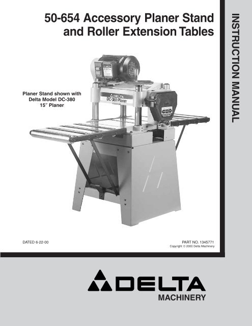
<strong>50</strong>-<strong>654</strong> <strong>Accessory</strong> <strong>Planer</strong> <strong>St<strong>and</strong></strong><strong>and</strong> <strong>Roller</strong> <strong>Extension</strong> <strong>Tables</strong><strong>Planer</strong> <strong>St<strong>and</strong></strong> shown withDelta Model DC-38015″ <strong>Planer</strong>INSTRUCTION MANUALDATED 6-22-00 PART NO. 1345771Copyright © 2000 Delta MachineryMACHINERY
INTRODUCTIONThis manual illustrates the st<strong>and</strong> with roller extension tables assembled to a Delta DC-380 15″ <strong>Planer</strong>. The accessoryheavy-duty steel planer st<strong>and</strong> not only gives a stable support surface for the 15″ planer, but is equipped with two rollerextension tables that provide added work support <strong>and</strong> prevent sniping of the wood when planing longer workpieces. Eachtable features four (4) large 2-1/4″ diameter rollers which will allow smoother, easier infeed <strong>and</strong> outfeed operations.UNPACKING AND CLEANINGYour 15″ planer st<strong>and</strong> with roller extension tables is shipped in one container. Carefully remove the protective coatingfrom the machined surfaces of the extension tables. This coating may be removed with a soft cloth moistened withkerosene. DO NOT USE ACETONE, GASOLINE OR LACQUER THINNER FOR THIS PURPOSE. Figure 2, illustratesthe components of the st<strong>and</strong>. Figure 3 illustrates the components of the roller extension tables.1. Side Supports (2)2. Upper <strong>St<strong>and</strong></strong> SupportBrackets (2)13. Lower <strong>St<strong>and</strong></strong> SupportBrackets (2)4. 5/16-18 x 3/4″ CarriageHead Screws (16)5. M8 Flat Washers (16)46. 5/16-18 Hex Nuts (16)7. M8 x 30MM Hex HeadScrews (4)8. M8 Flange Nuts (4)25679. M8.1 Lockwashers (4)398Fig. 21110. <strong>St<strong>and</strong></strong> Supports (2)181011. <strong>Roller</strong> <strong>Extension</strong> <strong>Tables</strong> (2)12. 1/4-20 x 3/4″ Hex HeadScrews (6)13. 1/4″ Flat Washers (8)14. 1/4-20 Hex Nuts (2)15. M6 x 20 Hex FlangeScrews (6)16. M6 Flange Nuts (6)17. Clips (2)18. Leg Support171213141516Fig. 32
ASSEMBLING STAND1. Assemble the two longer support brackets (A) Fig. 4,one of which is shown, to the inside of end panels (B) witheight 5/16-18 x 3/4″ carriage head screws (C), flatwashers, <strong>and</strong> 5/16-18 hex nuts. DO NOT COMPLETELYTIGHTEN HARDWARE AT THIS TIME.BDB2. Assemble the two shorter support brackets (D) Fig. 4,to the inside top of end panels (B) with the remainingeight 5/16-18 x 3/4″ carriage head screws (C), flat washers<strong>and</strong> 5/16-18 hex nuts. DO NOT COMPLETELY TIGHTENHARDWARE AT THIS TIME. NOTE: Make certain the toplip of support brackets (D) are positioned under the toplips of end panels (B) as shown in Fig. 4.ACFig. 4ASSEMBLING PLANER TO STANDE1. Carefully lift the planer (E) Fig. 5, onto the st<strong>and</strong> (B) asshown. CAUTION: EXTREME CARE SHOULD BE TAKENWHEN LIFTING THE PLANER ONTO THE STAND ASTHE CUTTERHEAD KNIVES ARE EXTREMELY SHARPAND THE PLANER IS VERY HEAVY. IF IT IS NOT DONEMECHANICALLY, A MINIMUM OF FOUR PEOPLE AREREQUIRED TO MANUALLY LIFT THE MACHINE.2. Align the four holes in the bottom of the planer (E)Fig. 5, with the mounting holes in the top of st<strong>and</strong> (B), <strong>and</strong>mount the planer to the st<strong>and</strong> with four M8 x 30MM hexhead screws (F) Fig. 5, lockwashers <strong>and</strong> flange nuts.NOTE: Screws (F) Fig. 6, one of which is shown, arestarted upward from the inside of st<strong>and</strong> (B). Later planermodels may not need flange nuts.BFig. 5F3. Once the planer is assembled to the st<strong>and</strong>, pushdown on top of the planer so the legs of the st<strong>and</strong> adjustto the floor surface. Tighten all st<strong>and</strong> mountinghardware.EBFFig. 63
ASSEMBLING SUPPORTBRACKETS TO ROLLEREXTENSION TABLES1. Place extension table (A) Fig. 7, on a firm supportingsurface. Align ends of support assembly (B) Fig. 7, withslotted holes (C) at both sides of extension table (A), <strong>and</strong>fasten support bracket assembly to extension table withtwo 1/4-20 x 3/4″ hex head screws <strong>and</strong> flat washers (D).IMPORTANT: In the position shown in Fig. 7, makecertain the longer side of notches (E) will be closest tohinge (F) of support table.2. Assemble the remaining support bracket to otherextension table in the same manner.EFCDDFig. 7BAASSEMBLING ROLLEREXTENSION TABLES TOPLANER AND STAND1. Assemble bracket clips (A) <strong>and</strong> leg support (F) Fig. 8,to the front <strong>and</strong> rear lower st<strong>and</strong> brackets (B), one ofwhich is shown assembled, with two 1/4-20 x 3/4″ hexhead screws (C), four flat washers (D) <strong>and</strong> two 1/4-20 hexnuts (E). Adjustment to height of clip can be made later.AEBFDCFig. 82. Align the three holes in the hinge of extension table(G) Fig. 9, with three holes in the front of the planer base(H) <strong>and</strong> loosely fasten the extension table to the planer asshown with three M6 x 20MM hex flange screws (K) <strong>and</strong>flange nuts. NOTE: Only finger tighten the three screws atthis time as height adjustment to the table will benecessary as explained later in STEP 4. Later planermodels may not need flange nuts.GKKH3. Place the notches at the bottom of extension tablesupport (B) Fig. 10, so the longer edge of the supportrests on the ledge of bottom support bracket (L) asshown. Adjust bracket clip (A) so it contacts the horizontalsupport bar (M). Tighten screw (N) after adjustment ismade. NOTE: Clip (A) acts as a safety device so theextension table will not fall accidentally during operationof the planer. Assemble the remaining roller extensiontable to the rear of the planer in the same manner.Fig. 9BMALN4Fig. 10
PAGFig. 11Fig. 124. IMPORTANT: Make certain the rollers on theextension tables are level with the table surface of theplaner. This will provide maximum work support <strong>and</strong>prevent sniping of the wood being planed.5. Place a straight edge (P) Fig. 11, on the table surface<strong>and</strong> extending out of the entire surface of the tableextension rollers as shown. Align the two surfaces <strong>and</strong>carefully tighten three screws (K) Fig. 9, that are holdingthe extension table to the base of the planer. Readjustbracket clip (A) if necessary.6. When not in use, the roller extension tables (G) Fig. 12,one of which is shown, can be lowered in front <strong>and</strong> backof the planer to prevent accidental movement, whichcould result in misalignment of the rollers. To lower thetables, raise the end of extension table (G) Fig. 13,slightly to relieve pressure on the table support (B) <strong>and</strong>move the table support inward away from clip (A), whilelowering extension table (G).GBFig. 13A7. Fig. 14, illustrates the st<strong>and</strong> with roller extensiontables assembled to a Delta 15″ DC-380 <strong>Planer</strong>.Fig. 145
MACHINERYPARTS, SERVICE OR WARRANTY ASSISTANCEAll Delta Machines <strong>and</strong> accessories are manufactured to high quality st<strong>and</strong>ards <strong>and</strong> are serviced by anetwork of Porter-Cable/Delta Factory Service Centers <strong>and</strong> Delta Authorized Service Stations. To obtainadditional information regarding your Delta quality product or to obtain parts, service, warranty assistance, orthe location of the nearest service outlet, please call 1-888-848-5175.MACHINERYDelta Building Trades <strong>and</strong> Home Shop MachineryTwo Year Limited WarrantyDelta will repair or replace, at its expense <strong>and</strong> at its option, any Delta machine, machine part, ormachine accessory which in normal use has proven to be defective in workmanship or material,provided that the customer returns the product prepaid to a Delta factory service center or authorizedservice station with proof of purchase of the product within two years <strong>and</strong> provides Delta withreasonable opportunity to verify the alleged defect by inspection. Delta may require that electricmotors be returned prepaid to a motor manufacturer’s authorized station for inspection <strong>and</strong> repairor replacement. Delta will not be responsible for any asserted defect which has resulted fromnormal wear, misuse, abuse or repair or alteration made or specifically authorized by anyone otherthan an authorized Delta Service facility or representative. Under no circumstances will Delta beliable for incidental or consequential damages resulting from defective products. This warranty isDelta’s sole warranty <strong>and</strong> sets forth the customer’s exclusive remedy, with respect to defectiveproducts; all other warranties, express or implied, whether of merchantability, fitness for purpose,or otherwise, are expressly disclaimed by Delta.6Printed in U.S.A.