Syntron® Electromagnetic Feeders - FMC Technologies
Syntron® Electromagnetic Feeders - FMC Technologies
Syntron® Electromagnetic Feeders - FMC Technologies

Create successful ePaper yourself
Turn your PDF publications into a flip-book with our unique Google optimized e-Paper software.
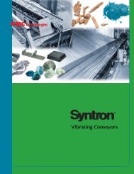
Heavy Duty <strong>Feeders</strong>
Look to <strong>FMC</strong> <strong>Technologies</strong> for exceptional value and performance in bulk material handling. For nearly 80years, we’ve partnered with our customers to solve material handling requirements in the most demandingand diverse industries and applications. Proven, low-maintenance and built to last, our Syntron ® line –backed by our expert team of engineers and application specialists – sets the standard for quality, performanceand reliability.<strong>FMC</strong> <strong>Technologies</strong> is committed to complete customer satisfaction, with fast, efficient solutions for mostbulk handling applications. From state-of-the-art electronic data capabilities, to expert sales and engineeringsupport specialists, we’re focused on ensuring a smooth design, production and installation process –from start to finish. Once you’re up and running, our customer service and field service teams are on call24/7 with technical assistance and service.Heavy-Duty <strong>Feeders</strong>The first name in vibration technology. Rugged and built tolast, Syntron ® bulk material handling equipment has a proventrack record for reliable, low-maintenance performance for awide range of industries and applications.
table of contentsSyntron ® Heavy-duty<strong>Feeders</strong>2Syntron ® <strong>Electromagnetic</strong>4<strong>Feeders</strong>Syntron ® Electromechanical<strong>Feeders</strong> 14Syntron ® RF Electromechanical<strong>Feeders</strong> 16Syntron ® MF Electromechanical<strong>Feeders</strong>18Syntron ® Feeder Controls 26Recommended Installation30GuidelinesSyntron ® Vibrators 33
Heavy-Duty <strong>Feeders</strong>Increase bulk handling productivity with controlledhigh feed rates that improve cost-per-ton handlingefficiency.
Syntron ® Heavy-Duty Vibrating <strong>Feeders</strong>Syntron ® Vibrating <strong>Feeders</strong> for heavy industry are ideal for feeding a widevariety of bulk materials from storage piles, hoppers, bins and silos. Ruggedand dependable, Syntron heavy-duty feeders are backed by years of serviceprovenperformance in the mining, aggregates, glass, cement, chemical,wood products and steel industries.Syntron Vibrating <strong>Feeders</strong> are designed to increase bulk handling productivitywith high, controlled feed rates to improve cost-per-ton efficiency.<strong>Electromagnetic</strong> and electromechanical models are available. With capacityranges from 25 to 4,000 tons per hour, these feeders are ideally suited forhigh-tonnage feeding. Feeder selection should include consideration of productionrequirements, material characteristics, and operating environment.Syntron Vibrating <strong>Feeders</strong> are sub-resonant tuned, two-mass, spring-connectedsystems. These features enable Syntron feeders to work consistently undermaterial damping and other varying headload conditions with negligiblechanges in trough stroke. Sub-resonant tuning maintains stroke consistencyand speed stability, thus delivering higher capacities at controlled feed rates.Precise, sub-resonant tuning is a key characteristic of both types of Syntronvibrating feeders. <strong>Electromagnetic</strong> models are tuned through careful calculationof the number and thickness of the special leaf springs required toaccomplish the desired tuning ratio. Electromechanical models are tuned byadjusting the operating speed to obtain the exact tuning ratio. Because subresonanttuning is so critical to feeder performance, a detailed explanationis provided for electromagnetic feeders on page 6 and for electromechanicalfeeders on page 15.Dependable, flexible control sets Syntron vibrating feeders apart from otherfeeding and conveying machinery. Material feed rates are controlled andeasily adjusted with Syntron solid-state controls; a wide range of standardand special models is available. Control devices can also be supplied forintegration into systems that use external signals from automatic sensingdevices. In addition, control arrangements are available for selecting andsequencing a group of feeders.<strong>Electromagnetic</strong> FeederSyntron ® F-Series<strong>Electromagnetic</strong> FeederElectromechanical <strong>Feeders</strong>Syntron ® MF ElectromechanicalFeederSyntron ® RF ElectromechanicalFeederMaterial Handling Solutions3www.fmctechnologies.com/materialhandling
Syntron ® <strong>Electromagnetic</strong> <strong>Feeders</strong>Syntron ® Heavy-Duty <strong>Electromagnetic</strong> <strong>Feeders</strong>Bulk material feeding with full-range control.Syntron ® Heavy-Duty <strong>Electromagnetic</strong><strong>Feeders</strong> come in tendifferent models with capacitiesranging from 25 to 1600 tons perhour.* These versatile feeders arecapable of handling a variety ofmaterials from the finest powdersto large, coarse particles.Syntron <strong>Electromagnetic</strong> <strong>Feeders</strong>can be supplied in various configurationsincluding multiple- driveunits and above-deck drive units.Above-deck drive units are recommendedwhere there is insufficientspace below the trough.Syntron <strong>Electromagnetic</strong> <strong>Feeders</strong>require minimal maintenance asthere are no mechanical parts to wearout, such as cams, eccentrics, beltsand bearings – thus eliminating theneed for lubrication. All movementis confined to the heavy-duty leafsprings. Electrical components, suchas the coil, will provide years ofservice under normal operatingconditions. Dust-tight drive unitsare standard on all models.Dependable, flexible controls provideeasily adjustable feed rates withinstantaneous response. A varietyof controls with special controlarrangements are available.(For more information onelectromagnetic feeder controls,see pages 26 - 28.)Syntron ®F-450 <strong>Electromagnetic</strong> <strong>Feeders</strong> feed sand in a glass factory.<strong>Electromagnetic</strong> Feeder Features■ Dust-tight and maintenance-free drive units■ Above- or below-deck drive units■ Two-mass, spring-connected, sub-resonant tuned■ High frequency - 3600 VPM at 60Hz■ Stroke - 0.060 inches■ Stroke generated by creating a magnetic field■ Suspension mount, base mount or combination of both■ Bolt-in replacement trough liners■ Multiple-drive unit feeders available* Based on dry sand weighing 100 pounds per cubic foot. Capacities vary depending on drive unit location, material characteristics, materialdensity, trough length and width, trough liner type, feeder installation, skirt boards and hopper transitions.4
Syntron ® F-380 <strong>Electromagnetic</strong> Feeder with above-deckdrive unit evenly distributes parts at a consistent rate toa heat treatment furnace.Feeding gypsum with Syntron model F-380<strong>Electromagnetic</strong> Feeder.Syntron ® <strong>Electromagnetic</strong><strong>Feeders</strong> are normally installedby suspension mounting withfour flexible wire rope cables.They can also be supplied forbase mounting on a solid base,or with a combination of basemounting and suspensionmounting.Syntron <strong>Electromagnetic</strong> <strong>Feeders</strong> are ideal for use in a stationary operation suchas a tunnel system from a surge pile. They are usually controlled from a remotepoint to provide the desired feed rate. In this application,a model FH-22 feeds limestone to a belt conveyor.Material Handling Solutions5www.fmctechnologies.com/materialhandling
Syntron ® <strong>Electromagnetic</strong> <strong>Feeders</strong> (cont’d.)Sub-Resonant Tuning for <strong>Electromagnetic</strong> <strong>Feeders</strong>Low sub-resonant tuning is the keycharacteristic of Syntron ®electromagnetic feeders, makingthem the most stable and consistentfeeders available on the market.Feeder tuning involves adjustmentof the natural frequency of thefeeder in relationship to itsoperating frequency. If the operatingfrequency is greater than the naturalfrequency, the feeder is superresonanttuned, making it veryunstable under headload. Conversely,if the natural frequency is greaterthan the operating frequency, thefeeder is sub-resonant tuned, makingit more consistent and stable underheadload.<strong>Electromagnetic</strong> feeders are tunedthrough careful calculation of thenumber and thickness of the specialleaf springs required to accomplishthe desired tuning ratio.Regardless of manufacturer, allheavy-duty, two-mass electromagneticvibrating feeders are subresonanttuned. For sub-resonanttuned feeders, the distance fromresonance is critical to feeder performance.Most manufacturers tunetheir feeders closer to resonance,while Syntron electromagneticfeeders are tuned further fromresonance.The natural frequency of all Syntron ® Heavy-Duty <strong>Electromagnetic</strong> <strong>Feeders</strong> ischecked at our test stations before shipment.Material damping and othervariations in headload causefluctuations in capacity and feedrates of all sub-resonant tunedfeeders. Because Syntron electromagneticfeeders are tuned furtherfrom resonance, capacity and feedrates remain more stable and consistenteven when the feeder issubjected to material damping andother variations in headload.This is why Syntron electromagnetic<strong>Feeders</strong> are the best solution forrugged material handlingapplications.6
<strong>Electromagnetic</strong> Feeder SpecificationsModel FH-22Approx.Trough Approx. Current Approx.W x L tph ◆ (460 V) Model Wt. (lb) Feeder/Control12 x 60 50 5 Amps CRSDC-2C 480 57518 x 42 125 5 Amps or 460 55524 x 42 170 5 Amps EVF-7.5D 480 575Please request a certified drawing for installation.◆ Based on feeder with 10˚ down slope, below-deck drive unit,installed with proper hopper transition and skirt board arrangement,feeding sand weighing 100 pounds per cubic foot. 240/480/600 Volt60 Hz single-phase. 230/400/415 Volt 50 Hz single-phase.Above-deck and base mounting drive units are available.A B C D E F G H J K L M N Pin 12 60 5 6 1 /2 66 1 /2 23 17 1 /2 16 1 /2 21 1 /2 8 1 /4 47 3 /4 10 1 /2 18 3 /4 19 3 /4mm 305 1524 127 165 1689 584 445 419 546 210 1213 267 476 502in 18 42 5 15 5 /16 57 5 /16 26 3 /4 17 1 /2 18 23 8 5 /16 40 9 24 3 /4 19 3 /4mm 457 1067 127 389 1456 679 445 457 584 211 1016 229 629 502in 24 42 5 15 5 /16 57 5 /16 32 3 /4 17 1 /2 18 23 8 5 /16 40 9 30 3 /4 19 3 /4mm 610 1067 127 389 1456 832 445 457 584 211 1016 229 781 502Model FH-24Approx.Trough Approx. Current Approx.W x L tph ◆ (460 V) Model Wt. (lb) Feeder/Control18 x 60 125 7 Amps CRSDC-2C 600 65024 x 48 195 7 Amps or 600 65030 x 36 200 7 Amps EVF-7.5D 600 650Please request a certified drawing for installation.◆ Based on feeder with 10˚ down slope, below-deck drive unit,installed with proper hopper transition and skirt boardarrangement, feeding sand weighing 100 pounds per cubic foot.240/480/600 Volt 60 Hz single-phase. 230/400/415 Volt 50 Hz singlephase.Above-deck and base mounting drive units are available.A B C D E F G H J K L M N Pin 18 60 5 6 5 /16 66 5 /16 28 19 5 /8 18 23 8 5 /16 47 1 /2 10 1 /2 24 3 /4 24 3 /4mm 457 1524 127 160 1684 711 498 457 584 211 1207 267 629 629in 24 48 5 12 5 /16 60 5 /16 32 3 /4 19 1 /4 18 23 8 5 /16 41 7 /8 10 1 /8 30 3 /4 19 3 /4mm 610 1219 127 313 1532 832 489 457 584 211 1064 257 781 502in 30 36 5 8 5 /16 54 5 /16 38 3 /4 19 1 /4 18 23 8 5 /16 37 9 36 3 /4 19 3 /4mm 762 914 127 135 1380 984 489 457 584 211 940 229 933 502Many other trough sizes are available. Capacities vary depending on drive unit location, material characteristics, material density,trough length and width, trough liner type, feeder installation, skirt boards and hopper transitions. Cad drawings are available.Please call <strong>FMC</strong> <strong>Technologies</strong> for expert help with your application.Material Handling Solutions7www.fmctechnologies.com/materialhandling
Syntron ® <strong>Electromagnetic</strong> <strong>Feeders</strong> (cont’d.)<strong>Electromagnetic</strong> Feeder Specifications, cont’d.Model F-330Please request a certified drawing for installation.Trough Approx. Approx. Approx.W x L Capacity Current Control Net Ship Wt. (lb)tph ◆ (460 V) Model Wt. (lb) Feeder/Control24 x 54 230 13 Amps CRSDC-2C 1130 120030 x 48 305 13 Amps or 1130 1200EVF-15D◆ Based on feeder with 10˚ down slope, below-deck drive unit,installed with proper hopper transition and skirt board arrangement,feeding sand weighing 100 pounds per cubic foot. 240/480/600 Volt60 Hz single-phase. 230/400/415 Volt 50 Hz single-phase. Above-deckand base mounting drive units are available.A B C D E F G H J K L M N Pin 24 54 6 21 1 /16 75 1 /16 35 7 /8 22 1 /2 21 27 12 15 /16 50 5 /8 11 1 /2 32 5 /8 24 3 /4mm 610 1372 152 535 1907 911 572 533 686 329 1286 292 829 629in 30 48 6 24 1 /8 72 1 /8 41 7 /8 22 1 /2 21 27 13 50 5 /8 8 1 /2 38 5 /8 24 3 /4mm 762 1219 152 613 1832 1064 572 533 686 330 1286 216 981 629Model F-380Trough Approx. Approx. Approx.W x L Capacity Current Control Net Ship Wt. (lb)tph ◆ (460 V) Model Wt. (lb) Feeder/Control24 x 60 230 18 Amps CRSDC-2C 1370 140030 X 60 330 18 Amps or 1400 145036 x 48 375 18 Amps EVF-15D 1400 1450Please request a certified drawing for installation.◆ Based on feeder with 10˚ down slope, below-deck drive unit,installed with proper hopper transition and skirt board arrangement,feeding sand weighing 100 pounds per cubic foot. 240/480/600 Volt60 Hz single-phase. 230/400/415 Volt 50 Hz single-phase. Above-deckand base mounting drive units are available.A B C D E F G H J K L M N Pin 24 60 6 18 1 /8 78 1 /8 35 7 /8 23 1 /4 22 3 /4 28 3 /4 12 7 /8 50 3 /4 14 1 /2 32 5 /8 32mm 610 1524 152 460 1984 911 591 578 730 327 1289 368 829 813in 30 60 6 18 1 /8 78 1 /8 41 7 /8 23 1 /4 22 3 /4 28 3 /4 12 7 /8 50 3 /4 14 1 /2 38 5 /8 36mm 762 1524 152 460 1984 1064 591 578 730 327 1289 368 981 91in 36 48 6 24 1 /8 72 1 /8 47 7 /8 23 1 /4 22 3 /4 28 3 /4 12 7 /8 50 3 /4 8 1 /2 44 5 /8 26 1 /4mm 914 1219 152 613 1832 1016 591 578 730 327 1289 216 1133 666Many other trough sizes are available. Capacities vary depending on drive unit location, material characteristics, material density,trough length and width, trough liner type, feeder installation, skirt boards and hopper transitions. Cad drawings are available.Please call <strong>FMC</strong> <strong>Technologies</strong> for expert help with your application.8
Syntron ® <strong>Electromagnetic</strong> <strong>Feeders</strong> (cont’d.)<strong>Electromagnetic</strong> Feeder Specifications, cont’d.Model F-480Trough Approx. Approx. Approx.W x L Capacity Current Control Net Ship Wt. (lb)tph ◆ (460 V) Model Wt. (lb) Feeder/Control42 X 84 665 31.5 Amps CRSDC-2C 4100 420048 X 72 780 31.5 Amps or 4000 4100EVF-25DPlease request a certified drawing for installation.◆ Based on feeder with 10˚ down slope, below-deck drive unit,installed with proper hopper transition and skirt boardarrangement, feeding sand weighing 100 pounds per cubic foot.480/600 Volt 60 Hz single-phase. 400/415 Volt 50 Hz single-phase.Above-deck and base mounting drive units are available.A B C D E F G H J K L M N Pin 42 84 7 23 15 /16 107 15 /16 54 3 /8 33 30 11 /16 37 11 /16 17 7 /16 71 1 /2 19 50 3 /4 51mm 1067 2134 178 608 2742 1381 838 779 957 443 1816 483 1289 1295in 48 72 7 28 1 /16 100 1 /16 60 3 /8 33 27 13 /16 34 13 /16 17 1 /2 61 5 /8 21 56 3 /4 57mm 1219 1829 178 713 2542 1534 838 706 884 445 1565 533 1441 1448Model F-560Please request a certified drawing for installation.Trough Approx. Approx. Approx.W x L Capacity Current Control Net Ship Wt. (lb)tph ◆ (460 V) Model Wt. (lb) Feeder/ControlCRSDC-2C54 X 72 820 27 Amps or 8500 9000EVF-25D◆ Based on feeder with 10˚ down slope, below-deck drive unit,installed with proper hopper transition and skirt boardarrangement, feeding sand weighing 100 pounds per cubic foot.480/600 Volt 60 Hz single-phase. 400/415 Volt 50 Hz single-phase.Above-deck and base mounting drive units are available.A B C D E F G H J K L M N Pin 54 72 8 48 3 /8 120 3 /8 66 3 /4 51 1 /2 35 1 /2 43 1 /2 21 3 /8 80 19 63 63 1 /2mm 1372 1829 203 1229 3058 1695 1308 902 1105 543 2032 483 1600 1613Many other trough sizes are available. Capacities vary depending on drive unit location, material characteristics, material density,trough length and width, trough liner type, feeder installation, skirt boards and hopper transitions. Cad drawings are available.Please call <strong>FMC</strong> <strong>Technologies</strong> for expert help with your application.10
Model F-660Trough Approx. Approx. Approx.W x L Capacity Current Control Net Ship Wt. (lb)tph ◆ (460 V) Model Wt. (lb) Feeder/ControlCRSDC-2C60 X 90 1000 31.5 Amps or 9200 9300EVF-25DPlease request a certified drawing for installation.◆ Based on feeder with 10˚ down slope, below-deck drive unit,installed with proper hopper transition and skirt boardarrangement, feeding sand weighing 100 pounds per cubic foot.480/600 Volt 60 Hz single-phase. 400/415 Volt 50 Hz single-phase.Above-deck and base mounting drive units are available.A B C D E F G H J K L M N Pin 60 90 8 40 130 72 1 /2 51 1 /2 39 1 /2 47 1 /2 21 1 /2 96 15 1 /2 69 63 1 /2mm 1524 2286 203 1016 3302 1842 1308 1003 1207 546 2438 394 1753 1613Model F-88Trough Approx. Approx. Approx.W x L Capacity Current Control Net Ship Wt. (lb)tph ◆ (460 V) Model Wt. (lb) Feeder/Control72 X 96 1600 70 Amps CRSDC-3C 11400 12000Please request a certified drawing for installation.◆ Based on feeder with 10˚ down slope, below-deck drive unit,installed with proper hopper transition and skirt boardarrangement, feeding sand weighing 100 pounds per cubic foot.480/600 Volt 60 Hz single-phase. 400/415 Volt 50 Hz single-phase.Above-deck and base mounting drive units are available.A B C D E F G H J K L M N Pin 72 96 8 49 9 /16 145 9 /16 87 51 1 /2 40 3 /32 48 3 /32 22 3 /4 103 9 /16 19 1 /4 82 63 1 /2mm 1829 2438 203 1259 3697 2210 1308 1018 1222 578 2630 489 2083 1613Many other trough sizes are available. Capacities vary depending on drive unit location, material characteristics, material density,trough length and width, trough liner type, feeder installation, skirt boards and hopper transitions. Cad drawings are available.Please call <strong>FMC</strong> <strong>Technologies</strong> for expert help with your application.Material Handling Solutions11www.fmctechnologies.com/materialhandling
Syntron ® <strong>Electromagnetic</strong> <strong>Feeders</strong> (cont’d.)<strong>Electromagnetic</strong> Feeder TroughsSyntron ® <strong>Electromagnetic</strong> Feeder models FH-22 through F-88 can be furnishedwith standard flat-bottom troughs, special flat-bottom troughs or belt-centeringdischarge troughs.Drive units can be positioned either above or below the trough. A below-deckdrive unit is most commonly used, but above-deck drive units can be suppliedfor installations where there is insufficient space below the trough. However,an above-deck drive unit may reduce feeder capacity slightly.Capacities for feeder models with standard troughs are based on sandweighing 100 pounds per cubic foot. Capacities vary depending on drive unitlocation, material characteristics, material density, trough length and width,trough liner type, feeder installation, skirt boards and hopper transitions.Several trough options are available for special applications. Syntron ® extralongfeeder troughs can be supplied with either below-deck or above-deckmultiple electromagnetic drive units. Extra-long feeder troughs provide manyadvantages in conveying materials over long distances; unlike belt conveyors,there are no idlers or pulley drive units to wear, lubricate, or replace. Longtubular troughs can convey pure, clean materials without atmospheric contaminationand safely convey dusty, poisonous materials without endangeringprocessing personnel.Other trough options include:• Syntron vibrating inspection tables feed material forward at a smooth,controlled rate of flow. This enables an operator to remove materialthat does not meet specification.• Syntron “spreader” feeders spread a wide, even layer of material witha diagonal discharge trough or diagonal-slotted trough.• Electrically heated trough liner plates minimize accumulation of damp orwet materials in feeder troughs. Available only on specially designed feeders,heated liner plates increase feeder efficiency by eliminating the downtimerequired to clean troughs. They are especially effective for materials withmoisture contents ranging from five to fifteen percent. The electric heatingelement is insulated and sandwiched between two steel plates.Diagonal discharge spreader feeder.Standard flat-bottom trough,below-deck drive unit.Tubular trough, below-deck driveunit.Flat bottom trough, above-deckdrive unit.Other Trough Options Include:■ Covered Trough with Dust Seals■■■■Open Trough with Dust SealsScreening <strong>Feeders</strong>Diagonal Discharge TroughBelt-Centering Discharge TroughTrough Liner Options Include:■ T-1A■■AR-400AR-500■ Stainless Steel■■■■UHMW PlasticRubberCeramicCarbide Overlay12
Multiple-Drive Unit <strong>Electromagnetic</strong> <strong>Feeders</strong>Syntron ® <strong>Electromagnetic</strong> drive units can be combinedto create feeders ideally suited for special applications.Multiple-drive units, positioned one behind the other,result in a long, vibrating conveyor. When an especiallywide material layer is desired, multiple-drive units canbe placed side by side on extra wide feeder troughs. Thenumber of drive units required is determined by thetrough width and length.Dual-twin drive units – two sets of twin drive units, oneset placed behind the other – provide both increasedcapacity and the ability to handle exceptionally heavy loads.The material flow rate of all multiple-drive unit modelscan be easily regulated. A special control permits adjustmentof all drive units simultaneously to control theflow rate of the entire feeder.Sixteen foot, triple drive unit Syntron ® F-440<strong>Electromagnetic</strong> Feeder conveyor.Syntron F-560 <strong>Electromagnetic</strong> Feeder with twodrive units.<strong>Electromagnetic</strong> drive units with tubular trough.An eight-foot wide by twenty-four inch long troughpowered by four Syntron F-330 electromagnetic driveunits.A selection of some of the available multiple-drive unitconfigurations.Material Handling Solutions13www.fmctechnologies.com/materialhandling
Syntron ® Electromechanical <strong>Feeders</strong>Syntron ® Electromechanical <strong>Feeders</strong>Increase bulk handling productivity with controlled high feed rate units.Syntron ® Heavy-Duty Electromechanical <strong>Feeders</strong>are available in a number of models with capacitiesranging from 400 to 4,000 tons per hour.* Abovedeckdrive units are available, but will provideslightly lower capacities.Syntron Electromechanical <strong>Feeders</strong> are ruggedlyconstructed to reduce maintenance and improveproduction efficiency.ControlsDependable, flexible solid-state control sets Syntronheavy-duty feeders apart from other feeding andconveying machinery. Feed rates are easily adjusted.Response is instantaneous. Control devices can besupplied for integration in systems using externalsignals from automatic sensing devices in instruments.Special control arrangements are also available forselecting and sequencing a group of feeders.Variable frequency controls for RF and MF feedersprovide linear feed rate and are available for eitherlocal or remote control operation. Control componentsare enclosed in a sturdy wall-mounted enclosure,and are available in general purpose, dust-tight,watertight or explosion-proof construction. Formore information about electromechanical feedercontrols, see page 29.Trough SelectionFeeder troughs for RF and MF feeders are one-pieceunitized weldments providing a rigid durable troughto meet application requirements. Troughs withbolt-together construction are available for tunnelinstallations or other confined areas.Standard finish includes High Solids Enamel Paint,International Red, 2.0 to 3.0 mils D.F.T. Stainlesssteel troughs are also available. Special coatingsand trough liners are available options to satisfyapplication requirements.Syntron ® RF-120 Electromechanical Feeder handles mediumloads.Syntron MF-200 Electromechanical Feeder feeding rock fromprimary crusher to belt conveyor.* Based on sand weighing 100 pounds per cubic foot.Capacities vary depending on material density, troughliner type, trough length, trough width, hoppertransitions and skirt board arrangement.14
Sub-resonant Tuning for Electromechanical <strong>Feeders</strong>Stroke consistency and speed stability for high-capacity feeding.Low sub-resonant tuning is the key characteristicof Syntron ® electromechanicalfeeders, making them the most stable andconsistent feeders available on the market.Feeder tuning involves adjustment of thenatural frequency of the feeder in relationshipto its operating frequency. If theoperating frequency is greater than thenatural frequency, the feeder is superresonanttuned, making it very unstableunder headload. Conversely, if the naturalfrequency is greater than the operatingfrequency, the feeder is sub-resonant tuned,making it more consistent and stable underheadload.Regardless of manufacturer, all heavy-duty,two-mass electromechanical vibratingfeeders are sub-resonant tuned. For subresonanttuned feeders, the distance fromresonance is critical to feeder performance.Most manufacturers tune their feederscloser to resonance, while Syntron feedersare tuned further from resonance.Material damping and other variations inheadload cause fluctuations in capacityand feed rates of all sub-resonant tunedfeeders. Because Syntron electromechanicalfeeders are tuned further from resonance,capacity and feed rates remain more stableand consistent even when the feeder issubjected to material damping and othervariations in headload. In addition, Syntronelectromechanical feeder design incorporatesinternal damping, which contributesto their stability and consistency.On the comparison chart (Figure 1), curve 1represents a typical competitive feeder ina no-load state without internal damping.Curve 2 represents a Syntron feeder in ano-load state with internal damping.Curve 3 represents a feeder with materialheadload and associated damping.Because Syntron feeders are tuned furtherfrom resonance and are designed withSub-Resonant Tuning forElectromechanical <strong>Feeders</strong>Figure 1. Comparison of Tuning Ratiosinternal damping, it is evident that theloss in relative trough stroke under headloadfor a Syntron feeder (Y) is negligibleas compared to a substantial loss in relativetrough stroke for competitive feeders (X).This is why Syntron electromechanicalfeeders are more consistent and stable thanany other feeder, even when subjected tomaterial damping and other variations inheadload.Material Handling Solutions15www.fmctechnologies.com/materialhandling
Syntron ® RF Electromechanical <strong>Feeders</strong>RF Medium-Duty Electromechanical <strong>Feeders</strong>These master material movers can feed it all.Syntron ® RF Medium-Duty ElectromechanicalVibrating <strong>Feeders</strong> meet the varying, mid-rangebulk material handling needs of industry.Capable of handling a wide range of materials,these two models provide feed rate capacitiesfrom 400 to 600 tons per hour.*Syntron RF feeders are two-mass vibrating units;the trough is one mass and the exciter unit isthe other. The exciter is belt-driven by a standardframeinduction motor and connected to thetrough with long-life polymeric shear springs.The ball bearings in the exciter unit have aminimum life expectancy of 20,000 L10 hours.Variable pitch motor sheaves provide a positivemethod of tuning. This Syntron design permitshigher feed capacities from smaller trough sizes,enabling you to select a more economical unit tomeet your capacity requirements.Variable operating speeds and trough stroke,combined with the damping characteristics ofpolymeric shear springs, are significant factorsin the performance capabilities of Syntron RFMedium-Duty Electromechanical <strong>Feeders</strong>.All Syntron RF Feeder motors are labeled forinverter duty and vibration service and arefurnished with a cast-iron frame. Special motorscan be supplied to meet UL explosion-proofrequirements.Two Syntron ® RF medium-duty electromechanical feedersfeeding coal onto a belt conveyor.* Based on dry sand weighing 100 pounds percubic foot. Capacities vary depending onmaterial density, trough liner type, troughlength, trough width, hopper transitions andskirt board arrangement.Syntron RF Electromechanical Feeder16
RF Medium-Duty Feeder SpecificationsModel RF-80Trough Capacity HP Approx. Control Net Ship Wt.W x L ◆ Current (460 V) Model Wt. Feeder/Control30 x 48 400 1 1.5 VF-1D 1150 135030 x 54 400 1 1.5 VF-1D 1200 1400◆ Based on feeder with 10˚ down slope, below-deck drive unit, installedwith proper hopper transition and skirt board arrangement, feedingsand weighing 100 pounds per cubic foot. 230/460/575 Volt 60 Hzthree-phase. 230/380/415 Volt 50 Hz three-phase.Please request a certified drawing for installation.A B C D E F G H J K L M N S max S min T U V Win 30 48 7 4 50 3 /16 43 1 /4 22 1 /2 16 1 /8 24 3 /8 7 3 /8 39 7 /8 6 5 /8 36 3 /4 42 17 6 5 1 1mm 762 1219 178 102 1275 1099 572 410 619 187 1013 168 933 1067 432 152 127 25 25in 30 54 7 4 51 3 /8 43 1 /4 22 1 /2 15 7 /8 25 1 /4 7 3 /8 46 1 /4 6 3 /4 36 3 /4 49 24 6 5 2 4mm 762 1372 178 102 1305 1099 572 403 641 187 1175 171 933 1245 610 152 127 51 102Model RF-120Trough Capacity HP Approx. Control Net Ship Wt.W x L ◆ Current (460 V) Model Wt. Feeder/Control36 x 60 600 2 3.0 VF-2D 1600 180036 x 72 600 2 3.0 VF-2D 1650 1850◆ Based on feeder with 10˚ down slope, below-deck drive unit, installedwith proper hopper transition and skirt board arrangement, feedingsand weighing 100 pounds per cubic foot. 230/460/575 Volt 60 Hzthree-phase. 230/380/415 Volt 50 Hz three-phase.Please request a certified drawing for installation.A B C D E F G H J K L M N S max S min T U V Win 36 60 8 4 56 7 /8 49 1 /4 25 1 /2 16 1 /2 26 15 /16 7 1 /8 53 1 /2 3 5 /8 42 3 /4 42 17 6 5 2 1 /2 4 1 /2mm 914 1524 203 102 1445 1251 648 419 684 181 1359 92 1086 1067 432 152 127 64 114in 36 72 8 4 62 1 /16 49 1 /4 25 1 /2 15 9 /16 28 1 /16 7 1 /8 63 1 /16 5 1 /8 42 3 /4 42 17 6 5 2 1 /2 6mm 914 1829 203 102 1576 1251 648 395 713 181 1602 130 1086 1067 432 152 127 64 152Many other trough sizes are available. Capacities vary depending on material density, trough liner type, trough length, trough widthand hopper transitions and skirt board arrangement. Cad drawings are available. Please call <strong>FMC</strong> <strong>Technologies</strong> for expert help withyour application.Material Handling Solutions17www.fmctechnologies.com/materialhandling
Syntron ® MF Electromechanical <strong>Feeders</strong>MF Heavy-Duty Electromechanical <strong>Feeders</strong>The high-capacity performers.Syntron ® MF Heavy-Duty Electromechanical <strong>Feeders</strong> arethe heavy-weights of bulk material handling and areused for higher capacity requirements. The eight heavydutymodels handle capacities from 600 to 4,000 tonsper hour.*Syntron Heavy-Duty Electromechanical <strong>Feeders</strong> combineextra structural strength with durable components. Thedeep wing plates form a bridge between inlet and dischargesuspension supports, providing extra strength foryears of dependable service. Standard troughs featureunitized weldments–one-piece, completely weldedunits for greater strength. Troughs are also availablewith bolt-together construction for tunnel installationsor other confined areas.MF Heavy-Duty Electromechanical <strong>Feeders</strong> are two-mass,spring-connected and sub-resonant-tuned. The exciterunit is connected to the trough with corrosion resistantpolymeric springs, which are more stable under varyingconditions. The springs are compressed for improvedload stability, improved feed angles and straight linemotion. The spring design eliminates pinch points, animportant safety feature. Exciters in these heavy-dutyfeeders use double roll, spherical roller bearings, withL10 expectancies up to 140,000 hours.All Syntron MF Electromechanical Feeder motors arelabeled for inverter duty and vibration service. Specialmotors can be supplied to meet UL explosion-proofrequirements.Attachments for safety cables are included on allSyntron MF feeders.Crusher Loading Feeder with peripheral discharge.* Based on sand weighing 100 pounds per cubic foot.Capacities vary depending on material characteristics,material density, trough length and width, trough linertype, feeder installation, skirt boards and hopper transitions.Syntron ® MF-200 Electromechanical Feeder feedingcrushed stone in an aggregate operation.18
MF Electromechanical Feeder Features■■■■■■■■■Operating frequency - 1100 VPM at 60HzStroke: 0.25 - 0.30 inchesStart and operate in empty or fully-loaded stateDependable, flexible, easily adjustable controlPrecise sub-resonant tuning ratio- Stroke consistency and speed stability undervarying material conditions- Reduces effects of varying headload andmaterial dampingStructural strength- Deep wing plates- Unitized weldmentsInfinite unbalance adjustment- Achieve desired stroke with easy adjustmentSuitable for use in hazardous areas- Explosion-proof motors required by coal, coke orother hazardous environments are availableBolt-in trough linersSyntron ® MF-400 Electromechanical Feeder feedingcoal from a truck dump hopper to a belt conveyor.Syntron MF-1600 Electromechanical Feeder feedingrock from the primary crusher to a belt conveyor.Syntron MF-600 Electromechanical Feeder feedingrock to a crusher.Material Handling Solutions19www.fmctechnologies.com/materialhandling
Syntron ® MF Electromechanical <strong>Feeders</strong> (cont’d.)MF Heavy-Duty Feeder SpecificationsModel MF-200Please request a certified drawing for installation.Approx. Approx. Approx. Approx.Trough Capacity HP Current Control Net Ship Wt. (lb)W x L (tph) ◆ (460 V) Model Wt. (lb) Feeder/Control36 x 72 600 5 7.0 Amps VF-5D 2200 280042 x 72 700 5 7.0 Amps VF-5D 2400 300048 x 84 900 5 7.0 Amps VF-5D 2500 310048 x 96 900 5 7.0 Amps VF-5D 2600 320054 x 96 1000 5 7.0 Amps VF-5D 2800 3400◆ Based on feeder with 10˚ down slope, below-deck drive unit, installedwith proper hopper transition and skirt board arrangement, feeding sandweighing 100 pounds per cubic foot. 460/575 Volt 60 Hz three-phase.380/415 Volt 50 Hz three-phase.A B C D E F G H J K L M N P R S T U V Win 36 72 8 2 1 /2 81 3 /16 60 1 /2 30 23 1 /8 35 5 /8 65 1 /4 8 3 /8 54 45 1 /2 21 3 /4 19 8 7 1 /4 2 2 9 7 /16mm 914 1829 203 64 2062 1537 762 587 905 1657 213 1372 1156 552 483 203 184 51 51 240in 42 72 8 4 81 1 /4 65 30 23 1 /8 35 5 /8 64 3 60 51 1 /2 21 3 /4 19 8 7 1 /4 4 3 4mm 1066 1829 203 102 2064 1651 762 587 905 1626 76 1524 1308 552 483 203 184 102 76 104in 48 84 8 4 87 1 /8 72 1 /2 30 22 1 /16 36 11 /16 71 1 /4 6 13 /16 66 57 1 /2 25 21 3 /4 9 8 -- 3 7 13 /16mm 1219 2134 203 102 2213 1842 762 560 932 1810 173 1676 1461 635 552 229 203 -- 76 198in 48 96 8 4 93 72 1 /2 30 21 37 3 /4 76 1 /4 10 7 /8 66 57 1 /2 25 21 3 /4 9 8 2 2 12mm 1219 2438 203 102 2362 1842 762 533 959 1937 276 1676 1461 635 552 229 203 51 51 305in 54 96 8 4 93 77 30 21 34 3 /4 74 7 /8 12 1 /8 72 72 21 3 /4 21 3 /4 8 8 2 2 10mm 1372 2438 203 102 2362 1956 762 533 883 1902 308 1829 1829 552 552 203 203 51 51 254Model MF-300Please request a certified drawing for installation.Approx. Approx. Approx. Approx.Trough Capacity HP Current Control Net Ship Wt. (lb)W x L (tph) ◆ (460 V) Model Wt. (lb) Feeder/Control36 x 72 800 5 7.0 Amps VF-5D 2300 290048 x 84 1200 5 7.0 Amps VF-5D 2600 3200◆ Based on feeder with 10˚ down slope, below-deck drive unit, installedwith proper hopper transition and skirt board arrangement, feeding sandweighing 100 pounds per cubic foot. 460/575 Volt 60 Hz three-phase.380/415 Volt 50 Hz three-phase.A B C D E F G H J K L M N P R S T U V Win 36 72 8 10 9 /16 84 59 30 24 1 /6 36 5 /6 65 1 /16 8 3 /6 54 45 1 /2 21 3 /4 19 8 7 1 /4 2 2 9 7 /16mm 914 1829 203 268 2134 1499 762 613 930 1653 213 1372 1156 552 483 203 184 51 51 240in 48 84 8 8 5 /16 86 5 /16 71 30 36 3 /4 37 11 /16 71 3 /16 6 13 /16 66 57 1 /2 21 3 /4 21 3 /4 8 8 3 7 13 /16mm 1219 2134 203 211 2192 1803 762 933 957 1808 173 1676 1461 552 552 203 203 25 76 198Many other trough sizes are available. Capacities vary depending on material density, trough liner type, trough length, trough width, hoppertransitions and skirt board arrangement. Cad drawings are available. Please call <strong>FMC</strong> <strong>Technologies</strong> for expert help with your application.20
Model MF-400Please request a certified drawing for installation.Approx. Approx. Approx. Approx.Trough Capacity HP Current Control Net Ship Wt. (lb)W x L (tph) ◆ (460 V) Model Wt. (lb) Feeder/Control54 x 84 900 10 12 Amps VF-10D 4500 520054 x 96 1000 10 12 Amps VF-10D 4600 530060 x 84 1000 10 12 Amps VF-10D 4600 530060 x 96 1200 10 12 Amps VF-10D 4800 540066 x 96 1400 10 12 Amps VF-10D 4900 560072 x 96 1600 10 12 Amps VF-10D 5100 5800◆ Based on feeder with 10˚ down slope, below-deck drive unit,installed with proper hopper transition and skirt board arrangement,feeding sand weighing 100 pounds per cubic foot. 460/575 Volt 60 Hzthree-phase. 380/415 Volt 50 Hz three-phase.A B C D E F G H J K L M N P R S T U V Win 54 84 8 2 1 /2 105 1 /16 80 1 /2 38 28 3 /8 42 15 /16 80 10 3 /4 74 63 1 /2 26 1 /2 21 3 /4 9 8 2 2 11 13 /16mm 1372 2134 203 64 2669 2045 965 721 1091 2032 273 1880 1613 673 552 229 203 51 51 300in 54 96 8 2 1 /2 113 5 /16 80 1 /2 38 28 3 /16 44 13 /16 85 5 /16 10 3 /4 74 63 1 /2 26 21 3 /4 9 8 2 2 11 13 /16mm 1372 2438 203 64 2878 2045 965 716 1138 2167 273 1880 1613 660 552 229 203 51 51 300in 60 84 8 2 1 /2 105 1 /16 88 1 /2 38 28 3 /8 42 15 /16 80 1 /2 10 3 /4 82 69 1 /2 26 1 /2 21 3 /4 9 8 2 2 11 13 /16mm 1524 2134 203 64 2669 2248 965 721 1091 2045 273 2083 1765 673 552 229 203 51 51 300in 60 96 8 8 113 5 /16 90 1 /2 38 28 3 /16 44 13 /16 85 3 /4 11 1 /4 84 69 1 /2 26 21 3 /4 9 8 2 2 12 5 /16mm 1524 2438 203 203 2878 2299 965 716 1138 2178 286 2134 1765 660 552 229 203 51 51 313in 66 96 8 2 1 /2 113 5 /16 96 1 /2 38 28 3 /16 44 13 /16 85 3 /4 11 1 /4 90 75 1 /2 26 21 3 /4 9 8 2 2 12 5 /16mm 1676 2438 203 64 2878 2451 965 716 1138 2178 286 2286 1918 660 552 229 203 51 51 313in 72 96 8 2 1 /2 114 3 /4 98 1 /2 38 28 3 /4 45 5 /16 86 1 /2 11 1 /4 92 81 1 /2 26 21 3 /4 9 8 2 2 12 5 /16mm 1829 2438 203 64 2915 2502 965 729 1151 2197 286 2337 2070 660 552 229 203 51 51 313Model MF-600Approx. Approx. Approx. Approx.Trough Capacity HP Current Control Net Ship Wt. (lb)W x L (tph) ◆ (460 V) Model Wt. (lb) Feeder/Control66 x 108 1600 15 18.5 Amps VF-15D 8300 910072 x 96 1800 15 18.5 Amps VF-15D 8100 8900Please request a certified drawing for installation.◆ Based on feeder with 10˚ down slope, below-deck drive unit,installed with proper hopper transition and skirt board arrangement,feeding sand weighing 100 pounds per cubic foot. 460/575 Volt 60 Hzthree-phase. 380/415 Volt 50 Hz three-phase.A B C D E F G H J K L M N P R S T U V Win 66 108 8 8 120 1 /8 99 45 30 1 /8 48 7 /8 94 13 5 /8 90 81 1 /8 32 1 /2 33 1 /4 11 3 /4 11 3 /4 2 2 14 11 /16mm 1676 2743 203 203 3051 2515 1143 765 1241 2388 346 2286 2061 826 845 298 298 51 51 373in 72 96 8 8 114 1 /4 105 45 31 3 /16 47 13 /16 85 3 /16 12 3 /4 96 87 1 /8 32 1 /2 33 1 /4 11 3 /4 11 3 /4 2 3 13 11 /16mm 1829 2438 203 203 2902 2667 1143 792 1214 2164 324 2438 2213 826 845 298 298 51 76 348Many other trough sizes are available. Capacities vary depending on material density, trough liner type, trough length, trough width, hoppertransitions and skirt board arrangement. Cad drawings are available. Please call <strong>FMC</strong> <strong>Technologies</strong> for expert help with your application.Material Handling Solutions21www.fmctechnologies.com/materialhandling
Syntron ® MF Electromechanical <strong>Feeders</strong> (cont’d.)MF Heavy-Duty Feeder Specifications, cont’d.Model MF-800Approx. Approx. Approx. Approx.Trough Capacity HP Current Control Net Ship Wt. (lb)W x L (tph) ◆ (460 V) Model Wt. (lb) Feeder/Control72 x 108 1800 20 25.5 Amps VF-20D 11550 1235084 x 108 2300 20 25.5 Amps VF-20D 12350 13150Please request a certified drawing for installation.◆ Based on feeder with 10˚ down slope, below-deck drive unit,installed with proper hopper transition and skirt board arrangement,feeding sand weighing 100 pounds per cubic foot. 460/575 Volt 60 Hzthree-phase. 380/415 Volt 50 Hz three-phase.A B C D E F G H J K L M N P R S T U V Win 72 108 10 8 1 /2 128 5 /8 107 50 32 7 /16 51 1 /8 93 1 /4 16 3 /8 96 87 1 /4 33 1 /4 33 1 /4 12 1 /2 11 3 /4 3 3 17 5 /8mm 1829 2743 254 216 3267 2718 1270 824 1299 2369 416 2438 2216 845 845 318 298 76 76 448in 84 108 8 8 128 5 /8 117 45 31 11 /16 51 1 /8 94 16 5 /8 108 99 1 /8 32 1 /2 33 1 /4 11 3 /4 11 3 /4 2 2 14 11 /16mm 2134 2743 203 203 3267 2972 1143 805 1299 2388 422 2743 2518 826 845 298 298 51 51 373Model MF-1000Approx. Approx. Approx. Approx.Trough Capacity HP Current Control Net Ship Wt. (lb)W x L (tph) ◆ (460 V) Model Wt. (lb) Feeder/Control72 x 120 2000 25 28.5 Amps VF-25D 13500 1450084 x 132 2500 25 28.5 Amps VF-25D 14000 15000Please request a certified drawing for installation.◆ Based on feeder with 10˚ down slope, below-deck drive unit,installed with proper hopper transition and skirt board arrangement,feeding sand weighing 100 pounds per cubic foot. 460/575 Volt 60 Hzthree-phase. 380/415 Volt 50 Hz three-phase.A B C D E F G H J K L M N P R S T U V Win 72 120 10 10 143 7 /16 109 58 33 1 /2 54 5 /16 106 1 /8 17 3 /8 98 87 1 /4 33 1 /4 33 1 /4 12 1 /2 11 3 /4 3 3 18 3 /4mm 1829 3048 254 254 3643 2769 1473 851 1380 2696 441 2489 2216 845 845 318 298 76 76 476in 84 132 10 10 149 3 /8 121 58 32 7 /16 55 3 /8 116 1 /2 16 5 /8 110 110 33 1 /4 32 1 /2 12 1 /2 11 3 /4 3 3 15mm 2134 3353 254 254 3794 3073 1473 824 1407 2959 422 2794 2794 845 826 318 298 76 76 381Many other trough sizes are available. Capacities vary depending on material density, trough liner type, trough length, trough width, hoppertransitions and skirt board arrangement. Cad drawings are available. Please call <strong>FMC</strong> <strong>Technologies</strong> for expert help with your application.22
Model MF-1600Approx. Approx. Approx. Approx.Trough Capacity HP Current Control Net Ship Wt. (lb)W x L (tph) ◆ (460 V) Model Wt. (lb) Feeder/Control90 x 132 3200 30 35.0 VF-30D 19800 21600Please request a certified drawing for installation.◆ Based on feeder with 10˚ down slope, below-deck drive unit,installed with proper hopper transition and skirt board arrangement,feeding sand weighing 100 pounds per cubic foot. 460/575 Volt 60 Hzthree-phase. 380/415 Volt 50 Hz three-phase.A B C D E F G H J K L M N P R S T U V Win 90 132 10 10 161 1 /8 127 80 36 11 /16 59 5 /8 113 1 /2 22 1 /2 116 116 53 53 27 27 4 4 19 1 /2mm 2286 3353 254 254 4093 3226 2032 932 1514 2883 572 2946 2946 1346 1346 686 686 102 102 495Model MF-2000The largest Syntron ® ElectromechanicalFeeder is the MF-2000. With a troughmeasuring 120-inches wide x 168-incheslong, the MF-2000 has capacities up to4,000 tph. Each one is custom built tomeet demanding capacity requirements.Please contact <strong>FMC</strong> <strong>Technologies</strong> fordimensions.A Syntron ® MF-2000 Electromechanical Feeder measuring72-inches wide by 240-inches long is custom built to feedcoal at 1000 tph.Many other trough sizes are available. Capacities vary depending on material density, trough liner type, trough length, trough widthand hopper transitions and skirt board arrangement. Cad drawings are available. Please call <strong>FMC</strong> <strong>Technologies</strong> for expert help withyour application.Material Handling Solutions23www.fmctechnologies.com/materialhandling
Syntron ® MF Electromechanical <strong>Feeders</strong> (cont’d.)Syntron ® Crusher Loading FeederThe new Syntron Crusher Loading Feeder is a traditional mechanical stylevibratory feeder with a peripheral discharge. The Crusher Loading Feederretains the high reliability and robust design of the mechanical feeder; theperipheral discharge, which has its origins in distribution of snack foods andcereals onto radial scales, enables equal distribution of fine and coarse product.The trough is fully lined to account for wear, and it is suspended by the samemethod as traditional vibratory feeders. The suspension framework is mountedon a trolley that can simply be moved out of the way for crusher maintenance.In side-by-side installations of a feeder-plus-rotary distributor and a SyntronCrusher Loading Feeder directly feeding the crusher, the Crusher LoadingFeeder delivered superior, cone-friendly performance. The specially configureddischarge blended fines and coarse materials to provide uniform distributionof material to the cone.In addition to the savings potential of reduced capital equipment costs, theSyntron Crusher Loading Feeder provides easy installation and maintenanceaccessibility. Like all Syntron feeders, the Crusher Loading Feeder is subresonanttuned and incorporates linear feed rate control to improve bulkhandling productivity. It can be sized to match application requirements.For more information, call 1-800-356-4899 and ask to speak with one ofour applications specialists.4-inch rock being distributedthrough the peripheral dischargeof the Crusher Loading Feeder.Blended material feeding directlyfrom the Crusher Loading Feederto the crusher.Material FlowUniform distribution of materialto the cone.Benefits of the Syntron ® CrusherLoading Feeder Include:■■■■■■One piece of equipmentLower amp draw on crusherLonger life for crusher wearcomponentsHigher crusher productivityEasier maintenance for the crusherImproved fracture ratio24
MF Heavy-Duty Feeder Trough StylesAll standard troughs are unitized welded constructionand can be supplied in a variety of materials. Specialcoatings and liners are available, including abrasionresistantsteel, manganese, stainless steel, urethane,UHMW plastic, rubber overlay and ceramic tiles.Optional above-deck drive units can be furnished forinstallations where there is insufficient space below thetrough. Covers, down spouts and belt centering dischargescan also be provided.Flat Bottom Troughs are standard.Tubular Troughs seal path of dusty materials.Grizzly Bar Sections for scalping or coarse screening.Belt Centering Discharge directs material on to a belt.Other Trough Options Include:■ Covered Trough with Dust Seals■ Open Trough with Dust Seals■ Screening <strong>Feeders</strong>■ Diagonal Discharge TroughTrough Liner Options Include:■ T-1A ■ Carbide Overlay■ AR-400 ■ Ceramic■ AR-500 ■ Rubber■ Stainless Steel ■ UHMW PlasticMaterial Handling Solutions25www.fmctechnologies.com/materialhandling
Syntron ® Feeder ControlsSyntron ® Heavy-Duty <strong>Electromagnetic</strong> Feeder ControlsEVF SeriesSyntron ® <strong>Electromagnetic</strong>Feeder Controls are solidstateunits that control material flow.Controls for electromagnetic feedersare EVF Series (VFD-type) and areoptimized for efficient operation.EVF Series controls feature a fullrange of adjustable control with a10:1 turn-down ratio. The newlydesigned EVF line of electromagneticfeeder controls are available insingle- or three-phase input withsingle-phase half-wave output thusallowing for reduced power consumptionwhen compared to ourlegacy CRSDC controls. Additionalfeatures of the new EVF productoffering include precise voltageregulation, expanded DC controlsignals and PC communication,and improved diagnostic capability.Please reference the chart belowfor model offerings or call one ofour applications specialists at1-800-356-4899 for additionalinformation.HzCertificationsControl Intermittent DC Signal Manual Output Voltage Soft VariableModel Input Voltage 50 60 Amps Enclosure Contacts Input Control RC Regulation Start Frequency UL CUL CEEVF-7.5D*EVF-15D*EVF-25D*EVF-50D*230, 380-460,575-600230, 380-460,575-600230, 380-460,575-600230, 380-460,575-600● ● 10 A Nema 1 ● ● Keypad ● ● ● ● ● ● ●● ● 21 A Nema 1 ● ● Keypad ● ● ● ● ● ● ●● ● 34 A Nema 1 ● ● Keypad ● ● ● ● ● ● ●● ● 60 A Nema 1 ● ● Keypad ● ● ● ● ● ● ●● Standard in the model listed* Available in Single-Phase or Three-PhaseCRSDC SeriesSyntron controls provide infinitevariable control of material feedrates. The CRSDC-2C Series controlsare the standard for Syntron Heavy-Duty <strong>Electromagnetic</strong> <strong>Feeders</strong>.They operate on half-wave rectificationof AC power and provideadjustable control with a 10:1turndown ratio. CRSDC-2C controlscontain an SCR (silicon controlledrectifier) and produce 3600 vibrationsper minute at 60 Hz operation.These compact controls conform toNational Electrical ManufacturersAssociation (NEMA) standards.HzCertificationsControl Intermittent DC Signal Manual Output Voltage Soft VariableModel Input Voltage 50 60 Amps Enclosure Contacts Input Control RC Regulation Start Frequency UL CUL CECRSDC-2CCRSDC-3C230, 400, 415 ●240, 480, 600 ●230, 400, 415 ●240, 480, 600 ●8-60 A Nema 4 ● ● Pot ● ● ●90 A Nema 4 ● ● Pot ● ● ●●Standard in the model listed26
<strong>Electromagnetic</strong> Feeder Control DimensionsOverall Dims (in.)Mtg. Dims (in.)Model Feeder Type A B C D E F G H J Weight (lbs)EVF - 7.5D F-22, FH-22, FH-24 7.88 12.72 7.22 3.01 7.31 11.93 0.28 0.12 – 18EVF - 15D F-330, F-380 7.88 12.72 7.22 3.01 7.31 11.93 0.28 0.12 – 29EVF - 25D F-440, F-450, F-480, F-560, F-660 9.84 15.9 8.08 4.33 8.9 15.12 0.39 0.39 – 29EVF - 50D F-88 14.57 23.19 10.24 5.22 13.19 22.05 0.51 0.72 0.71 79CRSDC-2C F-22 through F-660 19.75 19.75 8.25 9.14 18.11 20.56 0.34 0.125 – 53CRSDC-3C F-88 24 24 12 12.92 22.5 22.5 0.5 – – 72EVF SeriesEVF - 7.5D,EVF - 15DEVF -25DEVF - 50DCRSDC-2C SeriesCRSDC-2C, CRSDC-3CMaterial Handling Solutions27www.fmctechnologies.com/materialhandling
Syntron ® Feeder Controls (cont’d.)Syntron ® Heavy-Duty <strong>Electromagnetic</strong> Vibrating Feeder ControlsStandardElectronicFeeder ControlElectronic Control accepts a variable DC current or voltage signal from an external sourceand uses it to vary the feed rate.Two-RateAutomaticScalePerfect for batch weighing or bagging operations. External scale switches connected to controlautomatically signal primary fast material flow, secondary dribble flow, and instant shut-off atexactly the pre-selected weight. Primary and secondary setpoints are adjustable on keypad.LoadMonitoringControlSensor on electrical load of process equipment motors to determine when the machine isapproaching an overload or underload condition connected to control which adjusts feederoutput to correct machine loading.28
Syntron ® Electromechanical Feeder ControlsSyntron ® Electromechanical Feeder Controls arestate-of-the-art, solid-state units that can varymaterial flow rate.Controls for electromechanical feeders are VFSeries (variable frequency VFD-type) controls andare optimized for efficient operation. VF Seriescontrols feature a full range of adjustable controlwith a 10:1 turn-down ratio. Diagnostic featuresare additional benefits of VF controls.The VF Series controls are UL/CUL approved. Inaddition, a wide range of optional functions areavailable for specific control requirements.Variable-frequency controls offer total feed rate regulation throughmanual adjustment or PLC interface.Variable-Frequency ControlElectromechanical Feeder Control DimensionsOverall Dims (in.)Mtg. Dims (in.)Model* Feeder Type A B C D E F G H J Weight (lbs)VF - 1D RF-80 4.65 7.28 5.71 1.97 4.25 6.81 0.22 0.12 – 3.5VF - 2D RF-120 4.65 7.28 6.3 2.56 4.25 6.81 0.22 0.12 – 3.5VF - 5D MF-200, 300 5.91 10.24 6.31 3.01 5.32 9.63 0.26 0.12 – 10.5VF - 10D MF-400 7.88 12.72 7.22 3.01 7.31 11.93 0.28 0.12 – 17VF - 15D MF-600 7.88 12.72 7.22 3.01 7.31 11.93 0.28 0.12 – 17VF - 20D MF-800 9.84 15.9 8.08 4.33 8.9 15.12 0.39 0.39 – 29VF - 25D MF-1000 9.84 15.9 8.08 4.33 8.9 15.12 0.39 0.39 – 29VF - 30D, 40D MF-1600, 2000 9.84 15.9 8.08 4.33 8.9 15.12 0.39 0.39 – 32* Models VF-1D, VF-2D, VF-5D, VF-10D, and VF-15D are representative of IMAGE A below. Models VF-20 D, VF-25-D, and VF-30D represent IMAGE B.VF SeriesIMAGE AIMAGE BMaterial Handling Solutions29www.fmctechnologies.com/materialhandling
Recommended InstallationRecommended Designs for Hoppers and TransitionsFeeder Transition HoppersFeeder capacity depends on the design of the hopper. Material characteristicssuch as size distribution, shear properties and cohesiveness generallydictate the configuration of feeder transition hoppers. Material flowvelocities vary, depending upon material properties, feeder stroke andoperating speed.Good transition hopper design optimizes flow rate, resulting in the mosteconomical choice of a feeder. Improperly designed transition hoppers willsubstantially reduce feeder capacities.Figure 1 illustrates Ideal and Acceptable Hopper designs.The Ideal Hopperwith a throat (T) to gate height (H) ratio of 0.6 shows a uniform materialflow pattern to the feeder trough. Material at the front and rear of thehopper moves at nearly the same velocity, and the discharge depth (d) isnearly equal to the hopper gate height. The Ideal Hopper design allows themost economical feeder to be used.The Acceptable Hopper design may require a slightly larger feeder thanrequired for the Ideal Hopper design. This is due to the non-uniform flowpattern of material at the rear of the hopper. Material flow velocity isreduced, material depth “d” is reduced and there is a reduction in feedercapacity. A T/H ratio of 0.6 to 1.0 is generally acceptable. However, whenthe T/H ratio exceeds this range, the material flow patterns distortdrastically and will significantly reduce capacities.T = ThroatGF = Gate FactorH = Gate Height Opening R = Flow Rate (ft/min) ◆ See ChartC = CapacityW = Feeder Width (inches)d = Depth of Flow at DischargeCapacity (tons per hour) x 4800d (in) =[W (in) - 4 (in)] x R (ft/min) x D (lb/ft 3 )C (tph) =[W (in) - 4 (in)] x R (ft/min) x D (lb/ft 3 ) x d (in)4800H (in) = GF x d (in)◆ Flow Rate - R (ft/min)Suggested <strong>Electromagnetic</strong> SizeIf material size is -4-in with a trough down slope of up to 10˚, use 30-40 ft/min.If material size is +4-in to -12-in with a trough down slope of up to 10˚, use 25-30 ft/min.If material size is +12-in with a trough down slope of up to 10˚, use 20-30 ft/min.Suggested Electromechanical SizeIf material size is -4-in with a trough down slope of up to 10˚, use 50-60 ft/min.If material size is +4-in to -12-in with a trough down slope of up to 10˚, use 45-55 ft/min.If material size is +12-in with a trough down slope of up to 10˚, use 40-50 ft/min.Figure 1. Hopper DesignIdeal Hopper Promotes:■ Uniform flow pattern■ Maximum capacity■ Maximum material velocity■ Maximum material depth■ Optimized feeder size■ Reduced potential for material buildupat inlet■ Reduced potential for spillage at backand sides■ Reduced material load on feederFeeder down slope usually effects flow rate by 2% per degree. As down slopeincreases flow rate increases. As down slope decreases flow rate decreases.30
Recommended Hopper Design and Feeder SelectionRefer to Figure 2.1. Rear wall angle steep enough to permit material flow (60˚ ± 5˚).2. Front wall angle just enough to permit material flow (55˚ ±5˚).3. The throat dimension “T” for random size material should be aminimum of 2 times the largest particle of material. For particlesthat are nearly the same size (near size), “T” should be a minimumof 4 times the largest particle size to prevent blockage at the throatopening. In all cases, the arc “A” should exceed 2 1/2 times thelargest particle size.4. Gate opening “H” must be a minimum of 2 times the largestparticle of material and should increase proportionally for thedesired capacity. The most economical feeder is selected when thethroat dimension “T” is equal to or slightly larger than H/2. If “T” isgreater than “H” the flow pattern of the material is disturbed, resultingin non-uniform flow.5. When adjustable gates are used, the gate must be parallel to thehopper’s front wall and must be as close to the front wall as possible.The separation must not exceed 2 inches. The gate should act as anadjustable front wall. Leveling blades and down stream gates mustnot be used. Horizontal cut off gates should be used to performfeeder maintenance and must not be used to regulate flow.6. The inside width of the opening “D” (between stationary skirtboards)should allow for a 1-inch clearance between the feeder trough andskirt boards and should be a minimum of 2 1/2 times the largestparticle size. For near size material the width of “D” should be aminimum of 4 times the largest particle size.7. The minimum length of the feeder is determined by projecting theangle of repose for the specific material from the gate point to thefeeder pan and adding approximately 6 inches.8. The feeder must not contact any adjacent structure but must befree to vibrate. Allowance must be made for a decrease in feederelevation of approximately 2 inches, due to static material load. Inaddition, 1 inch minimum clearance at sides and 1 1/2 inches atbottom and back must be maintained in both loaded and unloadedconditions.9. The skirts must taper in the direction of flow (diverge fromconveying surface) to prevent material from jamming and causingadditional problems such as spillage and build-up. Skirts must runparallel to trough sides and must be reinforced to resist bulgingoutward against trough.Figure 2. Ideal Hopper IllustrationFor more information about hopper design,please request our free book or CD ROM,“Working with Hoppers.” Or, visit ourwebsite, call our Application Specialists at(662) 869-5711 or (800) 356-4899 or emailus at mhsol.info@fmcti.com.<strong>FMC</strong> <strong>Technologies</strong> offers free review and advice onyour hopper and Syntron ® feeder installation andisolation. Just send us your layout drawings.Material Handling Solutions31www.fmctechnologies.com/materialhandling
Recommended Installation (cont’d.)Feeder Mounting and IsolationBase MountingBase-mounted vibratory equipmentsits directly on isolation springsmounted on seats which attach tothe stationary support structuremade by others. The springs can besteel coil, polymeric or pneumatic.Suspension-mounted vibratory equipmenthangs from isolation assembliesattached to the overhead stationarysupport structure made by others.Suspension Mounting<strong>FMC</strong> <strong>Technologies</strong> recommends theuse of flexible wire rope for suspension-mountedvibratory equipment.A chart of the proper wire rope sizesis available on our website,www.fmcsyntron.com, in our freebook “Working with Isolation” and inour Service Instruction Manualswhich accompany the shipment ofequipment.<strong>Electromagnetic</strong> Feeder IsolationRF Feeder HangerMF Feeder HangerElectromechanical Feeder HangersWire Rope Diagram<strong>Electromagnetic</strong> Trough PostAngle HangerBail Hanger<strong>FMC</strong> <strong>Technologies</strong> suggests the useof link bar assemblies when a wirerope suspension is too short to beassembled in accordance with wirerope manufacturer recommendations.Contact <strong>FMC</strong> <strong>Technologies</strong> forappropriate link bar dimensions forspecific applications.Beam Hanger<strong>Electromagnetic</strong> Feeder HangersElectromechanical Dual Spring Isolation<strong>FMC</strong> <strong>Technologies</strong> does not recommendthe use of turnbuckles or rodswhen mounting vibratory equipment.Safety cables are recommended onall suspension-mounted vibratoryequipment.Link Bar AssemblyElectromechanical Single Spring IsolationMounting Lug for Wire Rope or Link Bar IsolationFor more information about feeder mounting and isolation, ask for our free book “Working with Isolation,” visitour website, call the Application Specialists at (662) 869-5711 or (800) 356-4899, or email us at mhsol.info@fmcti.com.32
Syntron ® VibratorsSyntron ® VibratorsSyntron ® Vibrators offer an efficient, cost-effectivemeans to maintain free flow of product from bins,hoppers and chutes, with a direct and positive result onthe bottom line. Whether the need is to ensure constant,uninterrupted material flow, or to eliminate the necessityfor manual manipulation of a bin, hopper or bulk material,Syntron Vibrators increase productivity and reduce productioncosts.Three types of Syntron Vibrators – electromagnetic,rotary electric and pneumatic – provide product flowsolutions for just about any industry, application orenvironment. Compact yet mighty, Syntron Vibrators aredesigned for years of high-performance, trouble-freecontinuous or intermittent operation, with the broadestselection of models and power ranges available.Syntron <strong>Electromagnetic</strong> Vibrators are ideal for continuousor intermittent operation. An easily adjustable controlassures optimum and variable material flow. DependableSyntron <strong>Electromagnetic</strong> Vibrators are virtually maintenance-freebecause the electromagnetic design eliminatesmoving parts. Most models come standard with fullyencloseddust-tight and watertight construction.Syntron Electric Rotary Vibrators are motor driven forreduced noise levels. These rugged vibrators are totallyenclosed for reliable operation in dusty, dirty or moistenvironments. Adjustable eccentric weights allow easyadjustment of force to suit varying applications.Syntron Pneumatic Vibrators can be installed whereelectricity is not readily available because they use compressedair. Two types of pneumatic vibrators, turbineand piston, are available. Designed to keep operatingnoise at a minimum, Syntron Pneumatic Turbine Vibratorsare ideal for locations where noise pollution is undesirable.Vibrator speed is adjusted by simply varying the air supply.Pneumatic turbine vibrators feature totally enclosedconstruction which eliminates concern over environmentalfactors such as dust, dirt or moisture.Syntron ® <strong>Electromagnetic</strong> VibratorsSyntron ® Electric Rotary Vibrators by VisamSyntron ® Pneumatic VibratorsMaterial Handling Solutions33www.fmctechnologies.com/materialhandling
Syntron ® serviceand supportAt <strong>FMC</strong> <strong>Technologies</strong>, we understand that good, reliableequipment – operating at peak performance – is crucial toyour bottom line. That’s why we’re committed to giving ourcustomers value – before, during and after the sale.Syntron Material Handling Solutions are based on the most rugged, reliable and durable vibratory equipmentavailable – Syntron vibrating feeders, conveyors, screens, parts feeders and bin vibrators. To begin with, we’llhelp you select the right equipment, considering all the variables of your application in order to maximize productionand reduce costs.Once you’re up and running, our Syntron Services Team will keep you on top and moving ahead. We’re on call–at the factory or in the field – wherever and whenever you need us for parts, service, inspection and training.Dependable equipment is critical to your operation, and your success is critical to our success.At <strong>FMC</strong> <strong>Technologies</strong>, your satisfaction is our number one priority. You can rely on us.www.fmctechnologies.com/materialhandlingCaution: Syntron ® Heavy-Duty <strong>Feeders</strong> must be installed, operated and maintained in accordance with accompanying <strong>FMC</strong><strong>Technologies</strong> Service Instructions. Failure to follow these instructions can result in serious personal injury, property damage or both.<strong>FMC</strong> <strong>Technologies</strong> Service Instructions accompany the shipment of equipment. If additional copies are required, they are available,free of charge from Material Handling Solutions, <strong>FMC</strong> <strong>Technologies</strong>, Inc., PO Box 1370, Tupelo, MS 38802.Material Handling Solutions37www.fmctechnologies.com/materialhandling
Product Offering• Belt Conveyor Idlers• Idler Rolls• Screw Conveyors• Bucket Elevators• Link-Belt ® Component Parts• Heavy-Duty Vibrating <strong>Feeders</strong>• Light-Duty Vibrating <strong>Feeders</strong>• Screening <strong>Feeders</strong>• Vibrating Screens• Vibra-Drive Units• Volumetric Feeder Machines• Grizzly Bar Screens• Vibrating Conveyors• Bin Vibrators• Packing Tables• Paper Joggers• Syntron ® Component PartsTechnisys Product Offering• Automation and Process Control• SCADA and Process Software• Variable Frequency Drives• DC Drives• Motors• Harmonic Filters• Line Reactors• Power Factor Correction• Enclosures (Metal, Fiberglass, Plastic)• Sensors• Transformers• Circuit Protective Devices• Industrial Controls• UL Panel Shop<strong>FMC</strong> <strong>Technologies</strong>, Inc.PO Box 1370Tupelo, MS 38802Tel: 662-869-5711Fax: 662-869-7493Toll Free: 800-356-4898Email: mhsol.info@fmcti.com<strong>FMC</strong> <strong>Technologies</strong>, Inc.2# Road No. 1Changshu Export Processing ZoneChangshu, Jiangsu, China 215513Tel: 86-0512-52299002Fax: 86-0512-52297228Email: mhsolchina.info@fmcti.com<strong>FMC</strong> <strong>Technologies</strong> Chile Ltda.Callao 2970, Office 704Las Condes, Santiago, ChileTel: 56 2 234 441856 2 246 4361Fax: 56 2 232 0825Email: fmc@entelchile.net<strong>FMC</strong> <strong>Technologies</strong>, Inc.479 West 900 NorthNorth Salt Lake, UT 84054Tel: 801-296-9500Fax: 801-296-9601Email: mhsol.info@fmcti.comwww.fmctechnologies.com/materialhandling© 2010 • <strong>FMC</strong> <strong>Technologies</strong>, Inc.Form No. 006-TUP Printed in U.S.A