Automated Planning: Theory & Practice
Automated Planning: Theory & Practice
Automated Planning: Theory & Practice

Create successful ePaper yourself
Turn your PDF publications into a flip-book with our unique Google optimized e-Paper software.
About the AuthorsMalik Ghallab is Directeur de Recherche at CNRS, the French national organizationfor scientific research. His main interests lay at the intersection of roboticsand AI, in the robust integration of perception, action, and reasoning capabilitieswithin autonomous robots. He contributed to topics such as object recognition,scene interpretation, heuristics search, pattern matching and unification algorithms,knowledge compiling for real-time synchronous systems, temporal planning, andsupervision systems. His work on the latter topic has been focused on the developmentof the IxTeT system for planning and chronicle recognition. IxTeT has beenapplied to robotics as well as to other domains, example, scheduling and processsupervision. Malik Ghallab is head of the French national robotics program Robeaand director of the LAAS-CNRS institute in Toulouse.Dana Nau is a professor at the University of Maryland in the Department ofComputer Science and the Institute for Systems Research. His research interestsinclude AI planning and searching as well as computer-integrated design andmanufacturing. He received his Ph.D. from Duke University in 1979, where he wasa National Science Foundation (NSF) graduate fellow. He has more than 250 technicalpublications. He has received an NSF Presidential Young Investigator award,an Outstanding Faculty award, several "best paper" awards, and several prizes forcompetition-level performance of his AI planning and game-playing programs. Heis a Fellow of the American Association for Artificial Intelligence (AAAI).Paolo Traverso is Head of Division at ITC-IRST in Trento, Italy. The Division isactive in the fields of automated planning, model checking, case-based reasoningand machine learning, distributed systems, and agents. His main research interestsinclude automated reasoning, planning under uncertainty, and the synthesisof controllers. He has contributed to research on mechanized metatheories, formalverification, knowledge management, embedded systems, and logics for the integrationof planning, acting, and sensing, for a list of recent publications. He is amember of the Editorial Board of the Journal of Artificial Intelligence Research, amember of the Executive Council of the International Conference on <strong>Automated</strong><strong>Planning</strong> and Scheduling, and a member of the Board of Directors of the ItalianAssociation for Artificial Intelligence.
ForewordI am very pleased to have this opportunity to write a foreword to <strong>Automated</strong> <strong>Planning</strong>:<strong>Theory</strong> and <strong>Practice</strong>. With this wonderful text, three established leaders inthe field of automated planning have met a long-standing need for a detailed,comprehensive book that can be used both as a text for college classes~completewith student exercises~and as a reference book for researchers and practitioners.In recent years, comprehensive texts have been written for several of the othermajor areas of Artificial Intelligence (AI), including machine learning, naturallanguageprocessing, and constraint satisfaction processing, but until now, the fieldof planning has been devoid of such a resource, despite the considerable number ofadvances in and the significant maturation of planning research in the past decade.With <strong>Automated</strong> <strong>Planning</strong>: <strong>Theory</strong> and <strong>Practice</strong>, Dana Nau, Malik Ghallab, andPaolo Traverso have filled that void and have done so with a remarkably clear andwell-written book.The authors made an important decision about what to emphasize in the text.Although, as they point out in the Preface, "the bulk of research on automatedplanning focuses on... classical planning," they decided not to devote a proportionalamount of their text to this restrictive framework but instead to showcase andemphasize techniques that move beyond the classical strictures. They don't ignoreclassical techniques: indeed, they provide a comprehensive coverage of them. Butthey then go on to provide ample coverage of such topics as temporal planningand resource scheduling, planning under uncertainty, and the use of a wide rangeof modern techniques for plan generation, including propositional satisfiability,constraint satisfaction, and model checking.Making good on its name, the book also includes a large section on the practice ofAI planning, including several case studies both of application classes such as robotplanning and of specific fielded applications such as the Deep Space 1 Remote Agentand the Bridge Baron game player. These case studies illustrate the process by whichthe relatively generic methods of automated planning are transformed into powerfuldomain-dependent tools and also show that, as a result of this transformation,automated planning can be made useful~that planning is good for much more thanjust stacking towers ofblocks. (Now if only I could transform my own bridge-playingstrategies so effectively!)<strong>Automated</strong> <strong>Planning</strong>: <strong>Theory</strong> and <strong>Practice</strong> is a terrific contribution to the AIliterature and will be widely used not only by those of us already active in the fieldof planning but also by our students and colleagues who want to know more thisimportant area of research.Martha E. PollackUniversity of Michiganxxi
PrefaceOne motivation for studying automated planning is very practical: the needfor information processing tools that provide affordable and efficient planningresources. Such tools are needed for use in complex and changing tasks that involvedemanding safety and/or efficiency requirements. They are needed for integratingmore autonomy and intelligent control capabilities in complex artifacts. <strong>Automated</strong>planning technology is already capable enough to be useful in a variety of demandingapplications, in areas ranging from controlling space vehicles and robots todeploying emergency operations and playing the game of bridge.Another motivation for automated planning is more theoretical. <strong>Planning</strong> is animportant component of rational behavior. If one purpose of Artificial Intelligence(AI) is to grasp the computational aspects of intelligence, then certainly planning,as the reasoning side of acting, is a key element in such a purpose.These two motivations create the potential for synergy between theory and practicein automated planning. By observing what works well in practice, it is possibleto develop better theories of planning. These better theories will in turn lead tobetter planning systems for practical applications.The intent of this textbook is to give readers an understanding of automatedplanning theory and automated planning practice and how they relate to eachother. The book contains a set of theoretical chapters to introduce the theory ofautomated planning and a set of case-study chapters to illustrate how to adapt andcombine automated planning techniques in a variety of application domains.Material CoveredThe published literature related to automated planning is quite large, and it is notfeasible in a single book to give detailed discussions of all of it. Our choice of whatto cover was motivated by the following considerations.The bulk of research on automated planning focuses on a restricted form calledclassical planning. We feel strongly that for the field of automated planning to realizeits full potential, it needs to move beyond classical planning. For that reason, whilecovering classical planning as prerequisite introductory material, we have devotedlarge parts of the book to extended classes of automated planning that relax thevarious restrictions required by classical planning.We also devoted a large part of the book to descriptions of application-orientedwork. These chapters are mainly illustrative case studies. From the application pointxxiii
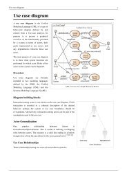
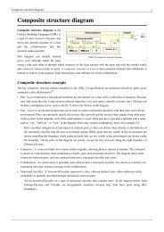
xxivPrefaceofview, the field ofplanning is still in an early stage. It has not yet developed a matureengineering methodology to enable us to present a comprehensive mapping fromthe features of an application domain to the planning techniques that best addressthese features. We do hope that this book can contribute to the development ofsuch a mature technology.Using This BookThis book may be used both as a graduate-level textbook and as an informationsource for professionals in the field. We assume that readers already know thebasic concepts of search algorithms, data structures, computational complexity,and programming languages at the level that one might get in an undergraduatecomputer science curriculum. Prior knowledge of heuristic search and first-orderlogic would also be helpful but probably is not strictly necessary since Appendices Aand B provide overviews of those topics.The book is composed of twenty-four chapters, which are organized into sevenparts, and three appendices. Parts I and II cover a restricted model ofplanning problemsand algorithms for planning within that model. Part III deals with heuristicsand control strategies for planning; and Parts III to V discuss several extended modelsand planning algorithms. Part VI is devoted to five case studies and applications.In Part VII, the last chapter discusses briefly other problems and techniques relatedto planning, example, planning and acting or planning and learning, to which itwas not possible to devote a full chapter.Figure 1 shows which chapters depend on which others. The required precedencerelationship is indicated by solid lines. The figure shows that one may proceedalong several possible paths when studying the book. In particular, several of theapplication-oriented chapters can be tackled quite early. The book contains morematerial than can fit into a single semester. The precedence relationship betweenchapters can help teachers decide which chapters to cover. 1Web SiteThe publisher's Web site offers additional material related to this book. It containslinks to related work; links to planning programs that may be downloaded atbooks.etsevier.com/m k/1558608567; copies of slides that have been used in lecturesbased on this book; and additional illustrations, examples, and exercises as may beappropriate.1. As an example of what can be covered in a single semester, a recent course on planning at theUniversity of Maryland covered the following chapters: 1, 2 (skipping set-theoretic representation),3, 4, 5, 6, a quick overview of 7, most ofg, 10, 11, 14, 15, most of 16, most of 17, 20, 22, and 23. Thecourse also included term projects in which the students, in groups of two or three people, proposedand carried out research projects on topics related to automated planning.
Prefacexxv. 1. IntroductionandOverview llLandr A.ComplexityJSearch 1.com0,ex, e0 .,or r F,r -OrOer } I 'c. oOe,' 1of Classical Classical [ Logic Checking<strong>Planning</strong> <strong>Planning</strong> ..\ \i,. ,a,e. oace l .P,an. o cel 6. P,annino- .Prooo,,,ona,<strong>Planning</strong> I " <strong>Planning</strong> I Graph SatisfiabilityTechniques Techniques~ I |' 8"C~ I "~1 9. Heuristicsl "~ IRulesin ,.I I ~ , Satisfaction _ . ..,,on I I ." inPlann.ng 9 I /\ I<strong>Planning</strong>_.! I I~ ! lecnnlques I I -- / N/'111. Hierarchical I 13. Time for 12. ControlTask Network I <strong>Planning</strong> Strategies in<strong>Planning</strong> | / \ Deductive <strong>Planning</strong>II // k \II/// ~ \~ .........~.1 116, <strong>Planning</strong> I ~ . . . . i I 15, <strong>Planning</strong> 17. <strong>Planning</strong>I ]4 lemporal I n R r9iI I Based on I I ~,~'lannlng. . . . la d esou ce Based on'[ I MDPs I I I I Scheduling Model Checking~ ~'~I ~@! <strong>Planning</strong> for 8 Uncer T t ain t9 20 <strong>Planning</strong> 19 Space "yManufacturability .." ....... g~ ('f^,,~ ....... .."~"~ with NeoclassicalAnal .... u .... %j, ~,-,vv,,u,~,,u,~,/ TechniquesE~v22. Emergency~X ~ ~. 23. <strong>Planning</strong> in~"~ 24. Conclusionscuation Plannina/~, ~x~e Game of Bridg~ and OtherTopicsFigure 1: Dependencies among the chapters. Boxes with rounded corners representappendices, boxes with square corners represent theoretical chapters, and ovalsrepresent case-study chapters. A solid line means that one chapter is needed in orderto understand another. A dashed line means that one chapter is not necessary foranother but may help the reader understand it more deeply. The dependencies forChapter 24 are not shown because each of its sections would need a different set oflines.
xxviPrefaceAcknowledgmentsWe wish to acknowledge the feedback from students who took courses based onvarious rough drafts of this book, in particular the students at the universities ofMaryland, Toulouse, and Trento and the ESSLL12002 summer school participants.Much thanks to our reviewers; their comments resulted in significant improvements.We are thankful to several colleagues and friends who gave us very valuablefeedback on parts of this book; among these are S. Biundo, University of Ulm;S. Chien, California Institute of Technology; K. Erol, Mindlore Inc.; M. Fox, Universityof Strathclyde; F. Kabanza, University of Sherbrooke; J. Koehler, Schindler Lifts;I. P. Laumond, LAAS-CNRS (Laboratoire d'Analyse et d'Architecture des Syst6mes,Centre National de la Recherche Scientifique); D. Long, University of California,Santa Cruz; A. Lotem, University of Maryland; H. Mufioz-Avila, University ofMaryland; M. Pistore, Instituto per la Ricerca Scientifica e Tecnologica/InstitutoTrend di Culture; A. Pogel, New Mexico State University; S. J. J. Smith, Great GameProductions; S. Thiebaux, Australian National University; D. Wilkins, SRI International;Q. Yang, Simon Fraser University. Thanks to M. Herrb and R. Prajoux, whohelped us set up the distributed CVS server and Latex environment. We also wish toacknowledge the support of our respective workplaces, which provided facilities thathelped make this work possible: LAAS-CNRS in Toulouse, France, the Universityof Maryland in College Park, Maryland, and ITC-IRST in Trento, Italy.
Table of NotationNotationa,AAcC,C8(u,m,a)8(w,u,m,a)effects(o)effects + (o)effects- (o)fgg+,gy(s,a)y-l(s,a)r(s)^r(s)r-l(g)~-~(g)hm,Mname(o)network(m)o, 0P = (O, so, g)Pa(s'ls)72p = (X, so, Sg)= (f, c)rr, FIMeaningActionSet of actionsConstraintSet of constraintsTask network produced from u by decomposing itwith the method m under the substitution aTask network produced from w by decomposing uwith the method m under the substitution aEffects of an operator or actionPositive effects of an operator or actionNegative effects of an operator or actionSet of tqes (temporally qualified expressions) or temporalconstraintsGoal formulaSets of positive and negative literals in gProgression, i.e., the state or set of states producedby applying a to sRegressionSet of all immediate successors of sTransitive closure of F(s)Set of all states whose immediate successors satisfy gTransitive closure of F -1 (g)Heuristic function, historyHTN method, set of methodsName of an operator or actionNetwork of subtasks of a method mOperator, set of operatorsStatement of a classical planning problemProbability of s' if a is executed in s<strong>Planning</strong> problemSet-theoretic or classical planning problemChronicle or temporal databasePlan, set of plans(continued)xxvii
xxviiiTable of NotationNotationprecond(o)precond+ (o)precond- (o)s,Sso, SoSgr= (S,A,•subtasks(m)tuT0(el.T)UW~(al,a2 ..... ak)( al, a2 .... , an)MeaningPreconditions of an operator or actionPositive preconditions of an operator or actionNegative preconditions of an operator or actionState, set of statesInitial state, set of initial statesSet of goal statesSubstitutionState-transition system, set-theoretic planning domain,or classical planning domainSubtasks of a method rnTask associated with a task node uDecomposition treeSet of enabling conditionsTask nodeTask networkConcatenation, e.g., e. E or E. e or E. E I, where e is an expressionand E, E I are sequencesComposition of two relations, e.g., rlor2k-tuple (where k is fixed)Sequence (where n may vary)
CHAPTER 1Introduction and Overview1.1 First Intuitions on <strong>Planning</strong><strong>Planning</strong> is the reasoning side of acting. It is an abstract, explicit deliberation processthat chooses and organizes actions by anticipating their expected outcomes.This deliberation aims at achieving as best as possible some prestated objectives.<strong>Automated</strong> planning is an area of Artificial Intelligence (AI) that studies thisdeliberation process computationally.Some of our actions require planning, but many do not. In our everyday activitieswe are always acting, and we do anticipate the outcome of our actions, even if weare not fully aware of anticipating [64]. But we act much more frequently than weexplicitly plan our actions: we are not often conscious of performing an explicitdeliberation process prior to acting. When the purpose of an action is immediategiven our knowledge of that action, or when we perform well-trained behaviorsfor which we have prestored plans, or when the course of an action can be freelyadapted while acting, then we usually act and adapt our actions without explicitlyplanning them.A purposeful activity requires deliberation when it addresses new situations orcomplex tasks and objectives or when it relies on less familiar actions. <strong>Planning</strong> isalso needed when the adaptation of actions is constrained, for example, by a criticalenvironment involving high risk or high cost, by a joint activity with someone else,or by an activity to be synchronized with a dynamic system. Since planning is a verycomplicated, time-consuming, and costly process, we resort to planning only whenit is strictly needed or when the trade-off of its cost versus its benefit compels us toplan. Furthermore, we generally seek only good, feasible plans rather than optimalplans[480].One motivation for automated planning is very practical: designing informationprocessing tools that give access to affordable and efficient planning resources.Some professionals face complex and changing tasks that involve demandingsafety and/or efficiency requirements. Imagine, as an example, a rescue operationafter a natural disaster such as an earthquake or a flood. That operation may involvea large number of actors and require the deployment of a communication andtransportation infrastructure. It relies on careful planning and the assessment ofseveral alternate plans. But it is also time constrained and it demands immediate
Chapter i Introduction and Overviewdecisions that must be supported with a planning tool. The need for such a toolis also felt by organizers of simpler and more mundane tasks such as organizinga social meeting or professional travel for a group of persons. At the individuallevel, a planning resource that is seamlessly integrated with electronic organizersor web services could be of great benefit in handling constraints, offering alternateplans not yet considered, and pointing out critical actions and what may need to berelaxed [443,445].Another motivation for automated planning is more theoretical. <strong>Planning</strong> is animportant component of rational behavior. If one purpose of AI is to grasp thecomputational aspects of intelligence, then certainly planning, as the reasoningside of acting, is a key element in such a purpose. The challenge here is to studyplanning not as an independent abstract process but as a fully integrated componentof deliberative behavior.An important combination of the practical and the theoretical motivations forautomated planning is the study and design of autonomous intelligent machines.Such a study is of practical concern because some of our complex artifacts suchas satellites and spacecraft require autonomy and deliberative behavior. These artifactscannot always be teleoperated because of operational constraints or becauseof a demanding interaction with nonexpert humans that is more natural at the tasklevel than at the low level of control signals. The study of autonomous intelligentmachines is also of theoretical concern because planning as a fully integrated componentof deliberative behavior requires embodiment into a machine that can senseand act as well as it reasons on its actions.1.2 Forms of <strong>Planning</strong>Because there are various types of actions, there are also various forms of planning.Examples include path and motion planning, perception planning and informationgathering, navigation planning, manipulation planning, communication planning,and several other forms of social and economic planning.Path and motion planning is concerned with the synthesis of a geometric pathfrom a starting position in space to a goal and of a control trajectory along thatpath that specifies the state variables in the configuration space of a mobile system,such as a truck, a mechanical arm, a robot, or a virtual character. Motion planningtakes into account the model of the environment and the kinematic and dynamicconstraints of the mobile system. It is a well-advanced area that appears today to bequite mature and offers a wide range of efficient and reliable methods.Motion planning can be seen as a particular case of the generic problem of planningcontrol actions for dynamic systems. While motion planning seeks a trajectoryin the configuration space of a mobile system, the generic planning problem is concernedwith more abstract state spaces. Consider, as an example, the problem ofcontrolling a ceramic plant or a blast furnace from its current state to a desired state.When these two states are close enough, a corrective control action can be computed
1.3 Domain-Independent <strong>Planning</strong> 3from their difference. If the desired state is too far apart from the current one (e.g.,for driving the furnace to a shutdown state), then a sequence of control actions thatmeets some constraints and criteria must be planned.Perception planning is concerned with plans involving sensing actions for gatheringinformation. It arises in tasks such as modeling environments or objects,identifying objects, localizing through sensing a mobile system, or more generallyidentifying the current state of the environment. An example of these tasks is thedesign of a precise virtual model of an urban scene from a set of images. Perceptionplanning addresses questions such as which information is needed and when it isneeded, where to look for it, which sensors are most adequate for this particulartask, and how to use them. It requires models of available sensors and their capabilitiesand constraints. It relies on decision theory for problems of which and wheninformation is needed, on mathematical programming and constraint satisfactionfor the viewpoint selection and the sensor modalities.Data gathering is a particular form of perception planning which is concernednot with sensing but instead with querying a system: e.g., testing a faulty device indiagnosis or searching databases distributed over a network. The issues are whichqueries to send where and in what order.Navigation planning combines the two previous problems of motion and perceptionplanning in order to reach a goal or to explore an area. The purpose ofnavigation planning is to synthesize a policy that combines localization primitivesand sensor-based motion primitives, e.g., visually following a road until reachingsome landmark, moving along some heading while avoiding obstacles, andso forth.Manipulation planning is concerned with handling objects, e.g., to buildassemblies. The actions include sensory-motor primitives that involve forces, touch,vision, range, and other sensory information. A plan might involve picking up anobject from its marked sides, returning it if needed, inserting it into an assembly,and pushing lightly till it clips mechanically into position.Communication planning arises in dialog and in cooperation problems betweenseveral agents, human or artificial. It addresses issues such as when and how toquery needed information and which feedback should be provided.There is a wide range of other kinds of planning problems, particularly in socialand economic realms. As examples, urban planning involves the deployment andorganization of an urban infrastructure (e.g., public transportation, schools, hospitals)in order to meet the needs of a community, family planning deals withdemography, and financial planning focuses on narrow financial optimization.1. 3 Domain-Independent <strong>Planning</strong>A natural approach for these diverse forms of planning is to address each problemwith the specific representations and techniques adapted to the problem.One develops predictive models for the type of actions to be planned for and for the
4 Chapter 1 Introduction and Overviewstates of the system in which they take place. Computational tools for running thesemodels, in order to predict and assess the effects of alternate actions and plans invarious situations, exploit the specifics of the domain. For example, geometry, kinematics,and dynamics are the tools needed for motion or manipulation planning.Mathematical programming and optimization techniques are the tools widely usedin various forms of economic planning.These domain-specific approaches to specific forms of planning are certainly welljustified. They are highly successful in most of the application areas mentionedearlier. However, they are frustrating for several reasons.9 Some commonalities to all these forms of planning are not addressed in thedomain-specific approaches. The study of these commonalities is needed forunderstanding the process of planning; it may help improve the domainspecificapproaches.9 It is more costly to address each planning problem anew instead of relying onand adapting some general tools.9 Domain-specific approaches are not satisfactory for studying and designing anautonomous intelligent machine. Its deliberative capabilities will be limited toareas for which it has domain-specific planners, unless it can develop by itselfnew domain-specific approaches from its interactions with its environment.For all these reasons, automated planning is interested in domain-independentgeneral approaches to planning. For solving a particular problem, a domainindependentplanner takes as input the problem specifications and knowledge aboutits domain. <strong>Automated</strong> planning is not meant to be opposed to domain-specificplanning techniques, just as automated reasoning is not intended to replace everyarithmetic and floating-point calculus processor and other specialized reasoningtechniques in a computer. Because planning is the reasoning side of acting, the purposeof automated planning is to develop general approaches to this particular formof reasoning that may build on and can be well integrated with domain-specificplanning tools.Domain-independent planning relies on abstract, general models of actions.These models range from very simple ones that allow only for limited forms ofreasoning to models with richer prediction capabilities. There are in particular thefollowing forms of models and planning capabilities.9 Project planning, in which models of actions are reduced mainly to temporaland precedence constraints, e.g., the earliest and latest start times of an actionor its latency with respect to another action. Project planning is used forinteractive plan edition and verification. A possible plan is given by the useras input to a project-planning tool that checks the feasibility of the constraintsand computes several useful attributes of the given plan such as its criticalpaths. Here, the models of the actions in the plan (i.e., their effects and theirinteractions) remain mostly in the mind of the user.
1.4 Conceptual Model for <strong>Planning</strong> 59 Scheduling and resource allocation, in which the action models include theabove types of constraints plus constraints on the resources to be used byeach action. A scheduling tool takes as input the actions to be carried outtogether with resource constraints and optimization criteria. The tool returnsa temporal organization and resource allocation for the given actions in orderto meet all the constraints and optimize the criteria.9 Plan synthesis, in which the action models enrich the precedent models withthe conditions needed for the applicability of an action and the effects of theaction on the state of the world. A plan synthesis tool takes as input the modelsof all known actions, a description of the state of the world, and some objective.The tool returns an organized collection of actions whose global effect, if theyare carried out and if they perform as modeled, achieves the objective.<strong>Automated</strong> planning is concerned with the general form of plan synthesis.Although it is still in its early stages theoretically, automated planning already isadvanced enough to be useful in demanding applications, several of which arediscussed in Part VI of this book.<strong>Automated</strong> planning already has several success stories; one is the control ofthe spacecraft Deep Space 1. This spacecraft was launched from Cape Canaveral onOctober 24, 1998, and was retired on December 18, 2001, after it completed its missionsuccessfully by encountering Comet BorreUy and returning the best images andother science data ever returned about a comet. The Deep Space I mission successfullytested a number of advanced technologies. Among these was the AutonomousRemote Agent software system. The Autonomous Remote Agent, which was basedon automated planning techniques, successfully operated Deep Space 1 betweenMay 17 and May 21, 1999. Chapter 19 discusses Deep Space I in greater detail.1. 4 Conceptual Model for <strong>Planning</strong>A conceptual model is a simple theoretical device for describing the main elementsof a problem. It can depart significantly from the computational concernsand algorithmic approaches for solving that problem. However, it can be veryuseful for explaining basic concepts, for clarifying restrictive assumptions, for analyzingrequirements on representations and trade-offs, and for proving semanticproperties.Since planning is concerned with choosing and organizing actions for changingthe state of a system, a conceptual model for planning requires a general model fora dynamic system. Most of the planning approaches described in this book rely ona general model, which is common to other areas of computer science, the modelof state-transition systems [146] (also called discrete-event systems).Formally, a state-transition system is a 4-tuple E = (S, A, E, y), where:9 S -- {Sl, S2 .... } is a finite or recursively enumerable set of states;
Chapter I Introduction and Overview9 A = {al, a2,...} is a finite or recursively enumerable set of actions;9 E = {el, e2,...} is a finite or recursively enumerable set of events; and9 ~,'S x A x E --, 2 s is a state-transition function.A state-transition system may be represented by a directed graph whose nodes arethe states in S. If s p ~ y (s, u), where u is a pair (a, e), a ~ A and e ~ E, then thegraph contains an arc from s to s p that is labeled with u. Each such arc is called astate transition. It can be convenient to introduce a neutral event E to account fortransitions that are due only to actions and, symmetrically, a neutral action no-opfor denoting transitions caused solely by an event. We write y (s, a, E) as y (s, a) and?'(s, no-op, e) as y(s, e).Example 1.1 Figure 1.1 shows a state-transition system involving a container in apile, a crane that can pick up and put down the container, and a robot thatcan can carry the container and move it from one location to another. Here,the set of states is {so, s~, s2, s3, s4, ss }, the set of actions is [take, put, toad, untoad,morel, move2}, and there are no events. The arc (so, sl) is labeled with the actiontake, the arc (s4, ss) with the action move2, and so forth. Each state transition isdeterministic, i.e., it leads to just one other state.IIBoth events and actions contribute to the evolution of the system. The differencelies in whether the planner has any control over them or not. Actions are transitionsthat are controlled by the plan executor. If a is an action and y(s, a) is not empty,then action a is applicable to state s; applying it to s will take the system to somestate in y (s, a). Events are transitions that are contingent: instead ofbeing controlledby the plan executor, they correspond to the internal dynamics of the system. Theyshould be taken into account by planning, but they cannot be chosen or triggered.If e is an event and y(s, e) is not empty, then e may possibly occur when the systemis in state s; its occurrence in s will bring the system to some state in y (s, e).A precise specification of the semantics of the transition function, as defined byy : S x A x E ~ 2 s, requires a refinement of this conceptual model. One model,the Markov game model, supposes that no action takes place in states where eventsoccur and vice versa. That is, S is partitioned into action states and event states. Analternative model is to suppose that actions can "compete" with events in the samestates. That is, ifwe apply a to s and y(s, e) is not empty, then the next state can beany element of y (s, a, e). 1Given a state transition system E, the purpose of planning is to find whichactions to apply to which states in order to achieve some objective when starting1. We will refer in Chapter 14 to a model where an action with time-dependent effects makes a statetransition and start a process that triggers, at some later state, an event that causes another statetransition [ 194 ].
1.4 Conceptual Model for <strong>Planning</strong> 7Figure 1.1 A state-transition system for a simple domain involving a crane and a robot fortransporting containers.from some given situation. A plan is a structure that gives the appropriate actions.The objective can be specified in several different ways.9 The simplest specification consists of a goal state Sg or a set of goal states Sg.In this case, the objective is achieved by any sequence of state transitions thatends at one of the goal states. For example, if the objective in Figure 1.1 isto have the container loaded onto the robot cart, then the set of goal states issg= {s4, s51.9 More generally, the objective is to satisfy some condition over the sequence ofstates followed by the system. For example, one might want to require states tobe avoided, states the system should reach at some point, and states in whichit should stay.
Chapter i Introduction and OverviewInitial state ~ Description of T_,"~I Planner]Objectives1 PlansI Controller IObservations T 1 Actions[ System Z IT EventsFigure 1.2 A simple conceptual model for planning.9 An alternative specification is through a utility function attached to states,with penalties and rewards. The goal is to optimize some compound functionof these utilities (e.g., sum or maximum) over the sequence of states followedby the system.9 Another alternative is to specify the objective as tasks that the system shouldperform. These tasks can be defined recursively as sets of actions and othertasks.It is convenient to depict this model through the interaction between threecomponents (Figure 1.2).1. A state-transition system Z evolves as specified by its state-transition functiony, according to the events and actions that it receives.2. A controller, given as input the state s of the system, provides as output anaction a according to some plan.3. A planner, given as input a description of the system Z, an initial situation,and some objective, synthesizes a plan for the controller in order to achievethe objective.An important element must be added to this model: the information that thecontroller has about the current state of the system. In general, this informationis not complete. Partial knowledge about the state can be modeled as an observationfunction r/: S---~ O that maps S into some discrete set O--{ol, o2 .... } ofpossible observations. The input to the controller is then the observation o = r/(s)corresponding to current state.Notice that the controller performs its task along with the dynamics of the statetransitionsystem. It works online with Z. On the other hand, the planner is notdirectly connected to Z. It works offline. It relies on a formal description of the
1. 5 Restricted Model 9Initial state--['Objectives ,,Execution statusObservations I~, Description of Y_,frlControllerPlans1 ActionsI System Y-, Il EventsFigure 1. 3 A conceptual model for dynamic planning.system, together with an initial state for the planning problem and the requiredgoal. It is concerned not with the actual state of the system at the time the planningoccurs but instead with what states the system may be in when the plan is executing.Most of the time, there are differences between the physical system to be controlledand its model, as described by E. In general, planning is restricted to themodel formally represented by E. The controller is supposed to be robust enough tocope with the differences between E and the real world. Dealing with observationsthat depart from what is expected in the plan requires more complex control mechanismsthan are needed for just observing the state and applying the correspondingaction. Several enhancements to this conceptual model are required to address adeliberative goal-directed behavior. A more realistic model interleaves planning andacting, with plan supervision, plan revision, and replanning mechanisms. There is aneed for a closed loop between the planner and the controller (Figure 1.3). The latterreturns to the planner the execution status of the plan to enable dynamic planning.1.5 Restricted ModelThis conceptual model is not meant to be directly operational. Instead, it will beused throughout this book as a reference for our representations. Let us considerit as a starting point for assessing various restrictive assumptions, particularly thefollowing ones.Assumption AO (Finite 1c). The system E has a finite set of states.Assumption A1 (Fully Observable E). The system E is fully observable, i.e., onehas complete knowledge about the state of ~. In this case the observation functionr/is the identity function.
10 Chapter 1 Introduction and OverviewAssumption A2 (Deterministic E). The system E is deterministic, i.e., for everystate s and for every event or action u, IF(s, u)l _< 1. If an action is applicable to astate, its application brings a deterministic system to a single other state; similarlyfor the occurrence of a possible event.Assumption A3 (Static E). The system Z is static, i.e., the set of events E is empty.E has no internal dynamics; it stays in the same state until the controller appliessome action. 2Assumption A4 (Restricted Goals). The planner handles only restricted goals thatare specified as an explicit goal state sg or set of goal states Sg; the objective is anysequence of state transitions that ends at one of the goal states. Extended goals suchas states to be avoided and constraints on state trajectories or utility functions arenot handled under this restricted assumption.Assumption A5 (Sequential Plans). A solution plan to a planning problem isa linearly ordered finite sequence of actions.Assumption A6 (Implicit Time). Actions and events have no duration; they areinstantaneous state transitions. This assumption is embedded in state-transitionsystems, a model that does not represent time explicitly.Assumption A7 (Offline <strong>Planning</strong>). The planner is not concerned with any changethat may occur in E while it is planning; it plans for the given initial and goal statesregardless of the current dynamics, if any.The simplest case, which we will call the restricted model, combines all eightrestrictive assumptions: complete knowledge about a deterministic, static, finitesystem with restricted goals and implicit time. Here planning reduces to thefollowing problem:Given Z = (S, A, F), an initial state so and a subset of goal states Sg, find asequence of actions (al, a2,..., ak) corresponding to a sequence of state transitions(so, Sl,..., Sk) such that Sl ~ F (so, al ), s2 ~ F (Sl, a2 ) .... , Sk ~ F (Sk- 1, ak ),and Sk ~ Sg.Since the system is deterministic, if F is applicable to s then F(s,a) containsone state s t. To simplify the notation, we will say F(s, a)= s r rather thanF(s, a) = {st}. For this kind of system, a plan is a sequence (al, a2,..., ak) such thatY ( F (... F ( F (so, al ), a2 ),..., ak- ] ), ak ) is a goal state.The assumption about complete knowledge (Assumption A0) is needed only atthe initial state so because the deterministic model allows all of the other states to2. This assumption is not properly named because the plan is intended precisely to change the state ofthe system; what is meant here is that the system remains static unless controlled transitions takeplace.
1.6 Extended Models 11be predicted with certainty. The plan is unconditional, and the controller executingthe plan is an open-loop controller, i.e., it does not get any feedback about the stateof the system.This restricted case may appear trivial: planning is simply searching for a pathin a graph, which is a well-known and well-solved problem. Indeed, if we are giventhe graph ]2 explicitly then there is not much more to say about planning for thisrestricted case. However even for a very simple application domain, the graph ]2can be so large that specifying it explicitly is not feasible. In the simple exampleintroduced earlier (Example 1.1), in which a robot has to move containers, supposethere are five locations, three pries of containers per location, three robots, andone hundred containers. Then ]2 has about 10277 states, which is about 10190 timesas many states as even the largest estimates [562] of the number of particles in theuniverse! Thus it is impossible in any practical sense to list all of ]2's states implicitly.Consequently, there is a need for powerful implicit representations that will enableus to describe useful subsets of S in a way that is compact and can easily be searched.Classical and neoclassical approaches to planning will be covered in Parts I and IIofthe book, respectively. Most of these approaches rely on an implicit representationbased on logic for describing states and on ad hoc state-transition operators forrepresenting actions. Specific rules and assumptions are required for defining andeasily computing the next state y(s, a).<strong>Planning</strong> as theorem proving, within the restricted model of this section, reliesentirely on a logic representation for describing both states and state-transitionoperators. The idea is to use a set of logical formulas to describe not just single statesbut instead the entire set of states and the relationships among them. This approachwill be covered in Part II.The remaining parts of the book consider other approaches in order to deal withless restricted models of planning.1.6 Extended ModelsSeveral interesting models are obtained by relaxing some of the restrictiveassumptions. We now review briefly the models that will be covered later.Relaxing Assumption A0 (Finite E). An enumerable, possibly infinite set of statesmay be needed, e.g., to describe actions that construct or bring new objects in theworld or to handle numerical state variables. This raises issues about decidabilityand termination to planners that will be discussed in Parts I and III.Relaxing Assumption A1 (Fully Observable E). If we allow a static, deterministicsystem to be partially observable, then the observations of ]2 will not fullydisambiguate which state E is in. For each observation o, there may be more thanone state s such that r/(s) = o. Without knowing which state in 7 -1 (o) is the currentstate, it is no longer possible to predict with certainty what state ]2 will be in aftereach action. This case will be covered in Part V.
12 Chapter 1 Introduction and OverviewRelaxing Assumption A2 (Deterministic Z). In a static but nondeterministicsystem, each action can lead to different possible states, so the planner may have toconsider alternatives. Usually nondeterminism requires relaxing assumption A5 aswell. A plan must encode ways for dealing with alternatives, e.g., conditional constructsof the form "do a and, depending on its result, do either b or c" and iterativeconstructs like "do a until a given result is obtained." Notice that the controller hasto observe the state s: here we are planning for closed-loop control.If the complete knowledge assumption (assumption A1) is also relaxed, this leadsto another difficulty: the controller does not know exactly the current state s of thesystem at run-time. A limiting case is null observability, where no observations at allcan be done at run-time. This leads to a particular case of planning for open-loopcontrol called conformant planning.Part V describes different approaches for dealing with nondeterminism. Some ofthem extend techniques used in classical planning (like graph-based or satisfiabilitybasedplanning), while others are designed specifically to deal with nondeterminism,like planning based on Markov Decision Processes (MDPs) and planning as modelchecking.Relaxing Assumption A3 (Static Z). We can easily deal with a dynamic system Zif it is deterministic and fully observable, and if we further assume that for everystate s there is at most one contingent event e for which ~, (s, e) is not empty andthat e will necessarily occur in s. Such a system can be mapped into the restrictedmodel: one redefines the transition for an action a as y(y(s, a), e), where e is theevent that occurs in the state y(s, a).In the general model of possible events that may or may not occur in a state and"compete" with actions, a dynamic system is nondeterministic from the viewpointof the planner even if IF(s, u)l _
1.7 A Running Example: Dock-Worker Robots 13when other assumptions are relaxed, as we have seen in the case of nondeterministicsystems (assumption A3) or when relaxing assumptions A1, A3, A4, and A6. Plansas partially ordered sets or as sequences of sets of actions, studied in Chapter 6 andin Part II, are more easily handled than conditional plans and policies that will beseen in Part V.Relaxing Assumption A6 (Implicit Time). In many planning domains, action durationand concurrency have to be taken into account. Time may also be needed forexpressing temporally constrained goals and occurrence of events with respect toan absolute time reference. However, time is abstracted away in the state-transitionmodel) This conceptual model considers actions or events as instantaneous transitions:at each clock tick, the controller synchronously reads the observation for thecurrent state (if needed) and applies the planned action. To handle time explicitlywill require an extension to our conceptual model; this will be considered in Part IV.Relaxing Assumption A7 (Offline <strong>Planning</strong>). The control problem of drivinga system toward some objectives has to be handled online with the dynamics ofthat system. While a planner may not have to worry about all the details of theactual dynamics, it cannot ignore completely how the system will evolve. At theleast, it needs to check online whether a solution plan remains valid and, if needed,to revise it or replan. Other approaches consider planning as a process that modifiesthe controller online. Issues with online planning will be surveyed in Part VI.These extensions cannot be handled directly within the restricted model.However, in some cases that we will illustrate later, they can be handled indirectly,possibly at the cost of a blowup of the domain description.1. 7 A Running Example" Dock-Worker RobotsWhenever possible, we will illustrate the planning procedures and techniques in thisbook on a simple yet nontrivial running example called the Dock-Worker Robots orDWR domain. Here we describe it only informally, but it will serve as an examplefor various planning formalisms throughout the book.The environment is a generalization of Example 1.1 (see page 6). It represents aharbor with several locations corresponding to docks, docked ships, storage areasfor containers, and parking areas for trucks and trains. This harbor is served byseveral robot carts and cranes that move containers in order to load and unloadships.3. Other formalisms, such as timed automata, extend state-transition systems with explicit representationof time.
14 Chapter i Introduction and OverviewAn abstract version of this domain can be defined by giving five finite sets ofconstant symbols plus one additional symbol.9 A set of locations {ll, 12,...}: A location can be a storage area, a dock, a dockedship, or a parking or passing area.9 A set of robots {rl, r2 .... }: Each robot is a container carrier cart that can beloaded and can transport just one container at a time. When a robot is withinsome location it can move to any other adjacent location.9 A set of cranes {kl,k2 .... }: A crane belongs to a single location; it canmanipulate containers within that location, between piles and robots.9 A set of piles {pl, p2 .... }: A pile is a fixed area attached to a single location.At the bottom of each pile is a pallet, on top of which are stacked zero or morecontainers.9 A set of containers {cl, c2,...}: A container can be stacked in some pile ontop of the pallet or some other container, loaded on top of a robot, or held bya crane.9 A symbol pallet: This denotes the pallet that sits at the bottom of a pile. Thereis no need to have separate symbols for individual pallets because each palletis uniquely identified by the pile it is in.Locations do not necessarily have pries. A location without pries is a parking orpassing area for robots. Any location that has pries also has one or more cranes.A crane can move a container from the top of a pile to an empty robot or to thetop of another pile at the same location. We will assume that a location can beoccupied by at most one robot at a time. The topology of the domain is denotedusing instances of the following predicates.9 adjacent(l, l'): Location l is adjacent to location l t.9 attached(p, l): Pile p is attached to location l.9 betong(k, l): Crane k belongs to location l.Those three predicates denote fixed relationships that do not change over time.The current configuration of the domain is denoted using instances of the followingpredicates, which represent relationships that change over time.9 occupied(l): Location l is already occupied by a robot.9 at(r,/): Robot r is currently at location l.9 loaded(r, c): Robot r is currently loaded with container c.9 unloaded(r): Robot r is not loaded with a container.9 hotding(k, c): Crane k is currently holding container c.9 empty(k): Crane k is not holding a container.
1.7 A Running Example: Dock-Worker Robots 159 in(c, p)" Container c is currently in pile p.9 on(c, c'): Container c is on some container c' or on a pallet within a pile.9 top(c, p): Container c sits on top of pile p. If pile p is empty, this will bedenoted as top(pallet, p).These nine predicates are not independent. For example, untoaded(r) holds if andonly if there is no c such that toaded(r, c) holds. Similarly, empty(k) holds if andonly if there is no c such that hotding(k, c) holds, and top(c, p) holds if and only ifthere is no container c t such that on(c t, c) holds. The reasons for these relationshipsand how they are maintained in the domain will be discussed in Chapter 2.There are five possible actions in the DWR domain.9 Move a robot r from some location l to some adjacent and unoccupiedlocation l t.9 Take a container c with an empty crane k from the top of a pile p colocatedwith k in the same location l.9 Put down a container c held by a crane k on top of a pile p colocated with kin the same location l.9 Load with a container c held by a crane k an unloaded robot r that is withinthe same location l.9 Unload a container c with empty crane k from a loaded robot r within thesame location l.More formal specifications of the DWR domain and several problem instancesare given in the rest of this book. 4Variants of the DWR Domain. At certain points, in order to give detailed explanationsof intricate data structures and algorithms, we will need a simpler version ofthe DWR domain. In the Simplified DWR domain, locations have no piles and nocranes, locations offer unlimited floor space for containers and robots, and everyrobot is equipped with an arm for loading and unloading a container. In this case,there are only three actions: moving, loading, and unloading.At various points, we also will enrich the DWR domain in order to illustrateenhanced planning possibilities. Chapter 20 will even describe a realistic instance ofthe domain that has been deployed experimentally. Here are some examples of thekinds of extensions we will consider.Space constraints are not taken into account in the basic domain. An explicithandling of space will require metric models. For example, one may slightly enrichthe domain by stating that a location can hold at most a given number of robots4. The web site at http://www.[aas.fr/ptanning/contains auxiliary material for this book. It includesthe <strong>Planning</strong> Domain Description Language specification and a few problem instances of the DWRdomain.
16 Chapter 1 Introduction and Overviewinstead of just one. Another extension is to allow more than one action to occurconcurrently because there are several independent robots and cranes. Resourceswill have to be made explicit in order to constrain the concurrency to nonconflictingactions. Realistically, explicit time is also needed because a feasible organizationof actions and resources is a function of durations. Goals also have to be constrainedin time (e.g., with respect to the arrival and departure of ships). Finally,partial information and uncertainty about the state of the world and about effectsof actions needs to be modeled.
1Classical <strong>Planning</strong>A restricted state-transition system is one that meets all of the restrictive assumptionsA0 through A7 given in Chapter 1. It is a deterministic, static, finite, and fullyobservable state-transition system with restricted goals and implicit time. Such asystem is denoted E--(S,A, F) instead of (S,A, E, Y) because there are no contingentevents. Here S, A, and Y are finite, and y(s, a) is a single state when a isapplicable to s.A planning problem for a restricted state-transition system E--(S,A, F) isdefined as a triple P = (E, so, g), where so is an initial state and g corresponds to aset of goal states. A solution to P is a sequence of actions (al, a2 ..... ak) correspondingtoa sequence ofstate transitions (so, Sl,..., Sk) such that Sl = Y(so, al),..., Sk -y(Sk-l,ak), and Sk is a goal state. The planning problem is to synthesize such asequence of actions.Classical planning refers generically to planning for restricted state-transitionsystems. 1 There are several motivations for studying classical planning problems.9 As usual in science when one is facing a very complex problem, it is very usefulto make restrictive assumptions in order to work out well-founded models andapproaches. In planning, assumptions A0 through A7 led to this baseline class.Classical planning is now a well-formalized and well-characterized problem.It is important, at least for pedagogical reasons, to have a good understandingof its representations and properties.9 Classical planning opened the way to algorithms and techniques that scale upreasonably well (presented in Parts II and III).1. This class of planning problems is also referred to in the literature as STRIPS planning, in referenceto STRIPS, an early planner for restricted state-transition systems [ 189].17
18 Part I Classical <strong>Planning</strong>9 As long as one keeps in mind that this is a restrictive and unrealistic model thatis not to be studied only for its own sake, many extensions to more realisticplanning models can be studied from this baseline (Parts III and IV).The main issues in classical planning are the following:9 How to represent the states and the actions in a way that does not explicitlyenumerate S,A, and y. Without such a representation, it is not possible todevelop domain-independent approaches to planning.9 How to perform the search for a solution efficiently: which search space, whichalgorithm, and what heuristics and control techniques to use for finding asolution.This part of the book is devoted to classical planning in two particular typesof search spaces: state spaces (Chapter 4) and plan spaces (Chapter 5). Chapter 2describes the representations used in classical planning. To explain why planningis a problem even in this restricted model, Chapter 3 analyzes the complexity ofclassical planning.
CHAPTER 2Representations for Classical<strong>Planning</strong>2.1 IntroductionA necessary input to any planning algorithm is a description of the problem tobe solved. In practice, it usually would be impossible for this problem descriptionto include an explicit enumeration of all the possible states and state transitions:Such a problem description would be exceedingly large, and generating it wouldusually require more work than solving the planning problem. Instead, a problemrepresentation is needed that does not explicitly enumerate the states and statetransitions but makes it easy to compute them on-the-fly.In this chapter, we discuss three different ways to represent classical planningproblems. Each of them is equivalent in expressive power, in the sense that a planningdomain represented in one of these representations can also be representedusing either of the other representations.1. In a set-theoretic representation (Section 2.2), each state of the world is a setof propositions, and each action is a syntactic expression specifying whichpropositions belong to the state in order for the action to be applicable andwhich propositions the action will add or remove in order to make a new stateof the world.2. In a classical representation (Section 2.3), the states and actions are like theones described for set-theoretic representations except that first-order literalsand logical connectives are used instead of propositions, This is the mostpopular choice for restricted state-transition systems.3. In a state-variable representation (Section 2.5), each state is represented by atuple of values of n state variables {Xl,..., Xn}, and each action is representedby a partial function that maps this tuple into some other tuple of values of then state variables. This approach is especially useful for representing domainsin which a state is a set of attributes that range over finite domains and whosevalues change over time.19
20 Chapter 2 Representations for Classical <strong>Planning</strong>There are also various ways to extend these approaches. Examples include the useoflogical axioms to infer things about states ofthe world and the use ofmore generallogical formulas to describe the preconditions and effects of an action. Section 2.4gives an overview of such approaches for classical representations.2.2 Set-Theoretic RepresentationIn this section we discuss set-theoretic representations of classical planningproblems. For brevity, we will usually call such problems set-theoretic planningproblems, and we will refer to the representation scheme as set-theoretic planning.2.2.1 <strong>Planning</strong> Domains, Problems, and SolutionsA set-theoretic representation relies on a finite set of proposition symbols that areintended to represent various propositions about the world.Definition 2.1 Let L = {Pl .... , Pn} be a finite set of proposition symbols. A set-theoreticplanning domain on L is a restricted state-transition system X = (S,A, y) suchthat:9 S _ 2 L, i.e., each state s is a subset of L. Intuitively, s tells us which propositionscurrently hold. If p ~ s, then p holds in the state of the world represented bys, and ifp r s, then p does not hold in the state of the world represented by s.9 Each action a cA is a triple of subsets of L, which we will write asa = (precond(a), effects-(a), effects + (a)). The set precond(a) is called the preconditionsof a, and the sets effects + (a) and effects-(a) are called the effectsof a. We require these two sets of effects to be disjoint, i.e., effects +(a) Neffects-(a) = 0. The action a is applicable to a state s ifprecond(a) _c s.9 S has the property that if s ~ S, then, for every action a that is applicableto s, the set (s - effects-(a)) U effects + (a) ~ S. In other words, whenever anaction is applicable to a state, it produces another state. This is useful to usbecause once we know what A is, we can specify S by giving just a few of itsstates.9 The state-transition function is y(s,a) -- (s - effects-(a)) U effects+ (a) ifa ~ A is applicable to s ~ S, and ~, (s, a) is undefined otherwise.IIDefinition 2.2A set-theoretic planning problem I is a triple P = (•, so, g), where:9 so, the initial state, is a member of S.1. When the meaning is clear from context, we will drop the adjective set-theoretic and just say planningdomain and planning problem.
2.2 Set-Theoretic Representation 219 g c_ L is a set ofpropositions called goal proposifions that give the requirementsthat a state must satisfy in order to be a goal state. The set of goal states isSg = {s ~ SIg c_ s}.IIDefinition 2.2 specifies what a planning problem is semantically, but it is not thesyntactic specification we would use to describe a planning problem to a computerprogram. The latter will be discussed in Section 2.2.3.Example 2.1 Here is one possible set-theoretic representation of the domain describedin Example 1.1.L = {onground, onrobot, hotding, at1, at2}, where:onground means that the container is on the ground;onrobot means that the container is on the robot;hotding means that the crane is holding the container;at1 means that the robot is at location 1; andat2 means that the robot is at location 2.S = {so,..., ss}, where:so = {onground, at2}; Sl = {hotding, at2};s2 = {onground, atl}; s3 = {hotding, atl}; ands4 = {onrobot, at1}; ss = {onrobot, at2}.A = {take, put, toad, untoad, move1, move2} where:take = ({onground}, {onground}, {hotding});put = ({holding}, {holding}, {onground});toad = ({hotding, atl}, (hotding}, {onrobot});unload = ({onrobot, atl}, {onrobot}, {hotding});move1 = ({at2}, {at2}, {at1}); andmove2 = ({atl}, {atl}, {at2}).IIDefinition 2.3 A plan is any sequence of actions Jr = (al,..., ak), where k > 0.The length of the plan is IJrl = k, the number of actions. If zq = (al .... ,ak)and zr2 = (a' 1 .... , a;) are plans, then their concatenation is the plan Zrl.Zr2 ='( al, .... ak, al, . . . , . IIThe state produced by applying Jr to a state s is the state that is produced byapplying the actions of Jr in the order given. We will denote this by extending thestate-transition function y as follows:sy(s, yr) = y(y(s, al), (a2,...,ak))undefinedif k = 0 (i.e., zr is empty)if k > 0 and al is applicable to sotherwise
22 Chapter 2 Representations for Classical <strong>Planning</strong>Definition z.4 Let P = (E, so, g) be a planning problem. A plan zr is a solution for P ifg c_ g (so, Jr). A solution Jr is redundant if there is a proper subsequence of Jr thatis also a solution for P; Jr is minimal if no other solution plan for P contains feweractions than Jr.INote that a minimal solution cannot be redundant.Example 2.2is so and g = {onrobot, at2}. Let:In the planning domain described in Example 2.1, suppose the initial state/rl -- (move2, move2)~r2 -- (take, movel)Jr3 - (take, movel, put, move2, take, movel, load, move2)~r4 - (take, movel, load, move2)zr5 - (movel, take, load, move2)Then Jr 1 is not a solution because it is not applicable to so; ~r2 is not a solutionbecause although it is applicable to so, the resulting state is not a goal state; Jr3 is aredundant solution; and ~4 and zr5 are the only minimal solutions.I2.2.2 State ReachabilityIf s is a state, then the set of all successors of s isr(s) = {y(s, a)l a ~ A and a is applicable to s}.Ifwe let l"2(s) = l"(1-'(s)) -- U{F(s t) [ st E 1-'(s)}, and similarly for F 3, ..., F n, thenthe set of states reachable from s is the transitive closure:I%(s) "-- I"(S) U l"2(S) U ....An action a is said to be relevant for a goal g iff g M effects + (a) # 0 and g Meffects-(a) = 0. Intuitively, these conditions state that a can contribute towardproducing a state in Sg - {s ~ S [ g c__ s}. Let us define the regression set of a goal g,for an action a that is relevant for g, to be the minimal set of propositions requiredin a state s in order to apply a to s and to get g:y-l(g, a) = (g - effects+(a)) U precond(a).Thus for any state s, V(s, a)6 Sg iff F -l(g,a) __c s, i.e., s is a superset of theregression set.
2.2 Set-Theoretic Representation 23The set of the regression sets over all actions relevant for a goal g is:F-l(g) = {y-1 (g, tl) [ g E A is relevant for g}.A goal state is reachable in a single step from a state s iff s is a superset of an elementof F-1 (g), i.e., there is s t E F-1 (g): s t _ s. Similarly, the set ofaU regression sets ofg in two steps is F-2(g) = F-1 (F-1 (g)), etc., and the set ofaU regression sets ofg,whose supersets are states from which g is reachable, is the transitive closure:~,-l(g) = r-l(g) U F-2(g) U ....Proposition 2.1 A planningproblem P = (}3, so, g) has a solution iff Sg N F(so) ~ O.Proposition 2.2 A planning problem P = (E, so, g) has a solution iff so is a superset ofsome element in ~-l (g).2.2. 3 Stating a <strong>Planning</strong> ProblemFor set-theoretic planning, we have defined the planning domain ~ = (S,A, y),which is independent of any particular goal or initial state, and the planning problemP = (E, so, g), which includes a domain, an initial state, and a goal.We began this chapter by mentioning the need for a way to specify P withoutgiving all of the members of S and y explicitly. To accomplish that, we willuse the statement of 7 ~, defined to be the triple P = (A, so, g). P and P can beregarded as semantic and syntactic specifications, respectively (for more about this,see Section 2.3.4).One difficulty is that the statement of a planning problem is ambiguous becauseit does not specify the set of states S (see Example 2.3).Example 2.3Let P = ({al},s0, g), where:al = ({pl}, {pl}, {p2})so = {pl}g = {p2}Then P is the statement of the planning problem P, in which:L = {pl, p2}S = {{pl}, {p2}}y({pl}, al) = {p2}
24 Chapter 2 Representations for Classical <strong>Planning</strong>However, P is also the statement of the planning problem "Pt, in which:L = {pl, p2, p3}S = {{pl}, {p2}, {pl, p3}, {p2, p3}}?,({pl}, al) = {p2}y({pl, p3},al)= {p2, p3}Note, however, that p3 plays no role in problem P': the set ~-l(g) of regressionsets and the set 1 ~ (so) of states reachable from so are the same in both P and pt.F'-I(g) = {{pl},{p2}};F'(so) = {{pl},{p2}}BThe following proposition generalizes the final equation:Proposition 2.3 Let 7 ) and P' be two planning problems that have the same statement.Then both 7 9 and 7 9' have the same set of reachable states I" (so) and the same set ofsolutions.This proposition means that the statement of a planning problem is unambiguousenough to be acceptable as a specification of a planning problem.2.2.4 Properties of the Set-Theoretic RepresentationWe now discuss some advantages and disadvantages of the set-theoretic representationscheme.Readability. One advantage of the set-theoretic representation is that it providesa more concise and readable representation of the state-transition system than wewould get by enumerating all of the states and transitions explicitly.Example 2.4 Consider the DWR domain shown in Figure 2.1. The robot can be at either[ocl or [oc2. The robot can be empty or can be holding any one of the containers,and likewise for the crane. The rest of the containers can be distributed in anyorder between pitel and pile2. The total number of possible states is 2,580,480(see Exercise 2.17). If we used a state-transition representation in which the stateswere named Sl, s2 ..... s2,580,480, it would be difficult to keep track ofwhat each statemeant.In a set-theoretic representation, we can make each state's meaning moreobvious by using propositions to represent the statuses of the containers, the
2.2 Set-Theoretic Representation 2 5Figure 2.1 A DWR state for Example 2.4.crane, and the robot. For example, the state shown in Figure 2.1 might be representedas:{nothing-on-c3, c3-on-c2, c2-on-cl, cl-on-pitel,nothing-on-c8, c8-on-c7, c7-on-c6, c6-on-c5,c5-on-c4, c4-on-pite2, robot-at-[oc2, crane-empty}Furthermore, the set-theoretic representation lets us avoid specifying all 2,580,480of the states (and their associated state transitions) explicitly because we can generatethem as needed using techniques such as the ones described next.mComputation. A proposition in a state s is assumed to persist in y(s, a) unlessexplicitly mentioned in the effects of a. These effects are defined with two subsets:effects + (a), the propositions to add to s, and effects- (a), the propositions to removefrom s in order to get the new state y(s, a). Hence, the transition function y andthe applicability conditions of actions rely on very easily computable set operations:if precond(a) __c_ s, then y (s, a) -- (s - effects- (a)) U effects + (a).Expressivity. A significant problem is that not every state-transition system E hasa set-theoretic representation. The work-around is to construct a state-transitionsystem E' that is equivalent to E but does have a set-theoretic representation (seeExample 2.5).Example 2.5 Suppose a computer has an n-bit register r and a single operator incrthat assigns r ~-- r d- I mod m, where m -- 2 n. Let L = (va[o,..., Vatm-1], whereeach vati is the proposition "the register r contains the value i." Then we canrepresent the computer as a state-transition system ~ = (S, A, ?'), where each stateis a member of L, A = {incr}, and y(va[i, incr) = va[i+l mod m for each i. Now,suppose that r contains some value c in the initial state and that the goal is for r
26 Chapter 2 Representations for Classical <strong>Planning</strong>to contain a prime number. Then the classical planning problem is 7:' = (E, so, g),where so = Va[c and Sg = {vat/ [ i is prime}.Ifwe use the above definitions for E and 7 9, then there is no set-theoretic actionthat represents incr, nor is there any set of propositions g _c 2 L that represents theset of goal states Sg. We can circumvent this difficulty by defining a state-transitionsystem E t and planning problem T 'r as follows:L' = L U {prime}S I = 2 L'A' = {incr0,..., incrm_l }{prime, vati+l mod m}?,'(vat/, incri) = {vati+l mod m}E' = (S', A', y')if i + I mod m is primeotherwiseSg - {s C 2L'I prime ~ s}']Y -- ( ~-,', SO, Sg,)7" has the following set-theoretic representation:g'= {prime};precond(incri) = {vat/}, i = 0 .... , neffects-(incri) = / {vat/}{vat/' --, prime} otherwiseif i primeeffects+(incri) = / {va[i+l mod m, prime} if i + 1 mod m is prime/ {va[i+ 1 mod rn} otherwiseHowever, creating this set-theoretic representation incurs a large computationalcost. There are 2 n different actions, and in order to write all of them, we mustcompute all of the prime numbers from I to 2 n.IIAnother expressivity issue with this representation scheme is that not every setof propositions in L corresponds to a meaningful state of a domain we are trying torepresent.Example 2.6 Consider the domain of Example 2.1 (see page 21). The state {hotding} isambiguous in our intended interpretation of the domain because it does not containa proposition that gives the robot location. Furthermore, the state {hotding, at2,
2.3 Classical Representation 2 7onrobot} is not consistent with our intended interpretation because it says that thecontainer is both on the crane and on the robot.IIIf the actions of a planning problem and so are written correctly, then an ambiguousor inconsistent state s will never appear in any solution to the planning problem:either s will not be reachable from so (i.e., s r F(so)) or g will not be reachable froms (i.e., s is not a superset ofan element off -l(g)). However, this puts all the burdenof a good definition of a domain on the specification of the set of actions.2. 3 Classical RepresentationThe classical representation scheme generalizes the set-theoretic representationscheme using notation derived from first-order logic. 2 States are represented assets of logical atoms that are true or false within some interpretation. Actions arerepresented by planning operators that change the truth values of these atoms.2.3.1 StatesTo develop a language for classical planning, we will start with a first-order languageE in which there are finitely many predicate symbols and constant symbols and nofunction symbols; thus every term of E is either a variable symbol or a constantsymbol. We will augment E to include some additional symbols and expressions. Forthe predicate and constant symbols of E, we will use alphanumeric strings that areat least two characters long (e.g., crane 1 or r2) with a sans-serif font. For the variablesymbols, we will use single characters, possibly with subscripts (e.g., x or Y13).A state is a set of ground atoms of E. Since E has no function symbols, the set Sof all possible states is guaranteed to be finite. As in the set-theoretic representationscheme, an atom p holds in s iffp ~ s. If g is a set of literals (i.e., atoms and negatedatoms), we will say that s satisfies g (denoted s ~ g) when there is a substitution asuch that every positive literal of a (g) is in s and no negated literal of a (g) is in s.Example 2.7 Suppose we want to formulate a DWR planning domain in which thereare two locations (tocl, toc2), one robot (rl), one crane (crane1), two piles(pl, p2), and three containers (cl, c2, c3). The set of constant symbols is{tocl, toe2, rl, crane1, pl, p2, cl, c2, c3, pattet}. Recall that pattet is a symbol thatdenotes the object that sits at the bottom of a pile; hence if a pile p3 is empty, thentop(pattet, p3). One of the states is the state Sl shown in Figure 2.2.II2. See Appendix B for an introduction and first-order logic.
28 Chapter 2 Representations for Classical <strong>Planning</strong>Figure 2.2 The DWR state Sl = {attached(pl,[ocl), attached(p2,[ocl), in(cl,pl), in(c3,pl),top(c3,pl), on(c3,cl), on(cl,pa[[et), in(c2,p2), top(c2,p2), on(c2,pa[[et),betong(cranel,[ocl), empty(crane1), adjacent([ocl,[oc2), adjacent([oc2,[ocl), at(rl,[oc2),occupied([oc2), unloaded(r1)}.Note that the truth value of an atom may vary from state to state. For example,at(rl,toc2) holds in the state depicted in Figure 2.2, but it does not hold in astate where robot rl moves to location [ocl. Hence, the predicate at can be consideredas a function of the set of states; it will be called a fluent or flexible relation.However, not every predicate symbol in E is necessarily fluent. For example, thetruth value of adjacent([ocl,toc2) is not intended to vary from state to state for agiven DWR domain. A state-invariant predicate such as adjacent is called a rigidrelation.Note also that although/~ is a first-order language, a state is not a set of firstorderformulasmit is just a set of ground atoms. Both here and in the set-theoreticrepresentation scheme, we use the closed-world assumption: an atom that is notexplicitly specified in a state does not hold in that state.2.3.2 Operators and ActionsThe transition function F is specified generically through a set of planning operatorsthat are instantiated into actions.Definition 2.5 In classical planning, a planning operator is a triple o = (name(o),precond(o), effects(o)) whose elements are as follows:9 name(o), the name of the operator, is a syntactic expression of the formn(xl,..., Xk), where n is a symbol called an operator symbol, Xl .... , Xk are allof the variable symbols that appear anywhere in o, and n is unique (i.e., notwo operators in/~ have the same operator symbol).9 precond(o) and effects(o), the preconditions and effects of o, respectively,are generalizations of the preconditions and effects of a set-theoretic
2.3 Classical Representation 29action: instead of being sets of propositions, they are sets ofliterals (i.e., atomsand negations of atoms).IIRigid relations cannot appear in the effects of any operator o because they areinvariant over all the states; they can be used only in precond(o). In other words,any predicate in effects(o) is a flexible relation.Rather than writing o = (name(o), precond(o), effects(o)) to define a planningoperator, we will usually write operator definitions as shown in Example 2.8.Example 2.8Here are the planning operators for the DWR domain.move(r, l, m),, robot r moves from location l to an adjacent location mprecond: adjacent(l, m), at(r, l), --, occupied(m)effects: at(r, m), occupied(m), -, occupied(l), --, at(r, l)toad(k, l, c, r);; crane k at location l toads container c onto robot rprecond: belong(k, l), holding(k, c), at(r, l), unloaded(r)effects: empty(k),-, holding(k, c), loaded(r, c), --, unloaded(r)unload(k, l, c, r),, crane k at location I takes container c from robot rprecond: belong(k, l), at(r, l), loaded(r, c), empty(k)effects: -, empty(k), holding(k, c), unloaded(r), --, loaded(r, c)put(k, l, c, d, p);; crane k at location l puts c onto d in pile pprecond: belong(k, l), attached(p, l), holding(k, c), top(d, p)effects: -,hotding(k,c),empty(k),in(c,p),top(c,p),on(c,d),-,top(d,p)take(k, l, c, d, p);; crane k at location l takes c off of d in pile pprecond: belong(k, l), attached(p, l), empty(k), top(c, p), on(c, d)effects: hotding(k,c),-~empty(k), --, in (c, p), --, top(c, p), --, on (c, d),top(d,p)IIThe purpose of an operator's name is to provide an unambiguous way torefer to the operator or to substitution instances of the operator without havingto write their preconditions and effects explicitly. If o is an operator or an operatorinstance (i.e., a substitution instance of an operator), then name(o) refers unambiguouslyto o. Thus, when it is clear from the context, we will write name(o) torefer to the entire operator o.
3oChapter 2 Representations for Classical <strong>Planning</strong>Example2,.9 take( k, l, c, d, p ) is the last of the operators in Example 2.8, andtake(cranel,locl,cl,c2,pl) is the following operator instance:take( crane 1,[oc 1 ,c 1 ,c2, p 1 );; crane crane1 at location [ocl takes cl off of c2 in pile plprecond: belong(cranel,[ocl), attached(pl,[ocl),empty(crane1), top(cl,pl), on(cl,c2)effects: holding(cranel,cl), -~empty(cranel), -~in(cl,pl),-~top(cl,pl),-~on(cl,c2), top(c2,pl)Definition 2.6 For any set of literals L, L + is the set of all atoms in L, and L- is theset of all atoms whose negations are in L. In particular, if o is an operator oroperator instance, then precond § (o) and precond- (o) are o's positive and negativepreconditions, respectively, and effects + (o) and effects- (o) are o's positive andnegative effects, respectively.mDefinition 2. 7 An action is any ground instance of a planning operator. If a is an actionand s is a state such that precond+(a) _ s and precond-(a) N s = 0, then a isapplicable to s, and the result of applying a to s is the state:~, (s, a) = (s - effects- (a) ) U effects + (a).Thus, like in set-theoretic planning, state transitions can easily be computedusing set operations.Example 2.10 take(cranel,locl,c3,cl,pl) is applicable to the state Sl of Figure 2.2. Theresult is the state s5 = )/(Sl, take(crane1, locl, cl, c2, pl)) shown in Figure 2.3.IIBIIFigure 2,. 3 The DWR state s5 = {attached(pl,locl), in(cl,pl), top(cl,pl), on(cl,pallet),attached(p2,[ocl), in(c2,p2), top(c2,p2), on(c2,pallet), belong(cranel,[ocl),holding(cranel,c3), adjacent([ocl,loc2), adjacent(loc2,[ocl), at(rl,[oc2), occupied([oc2),unloaded(r1)}.
2.3 Classical Representation 312.3.3 Plans, Problems, and SolutionsHere are the definitions of classical planning domains, problems, plans, andsolutions.Definition 2,.8 Let/~ be a first-order language that has finitely many predicate symbolsand constant symbols. A classical planning domain 3 in /~ is a restrictedstate-transition system E = (S, A, y) such that:9 S c 2 {all ground atoms of L};9 A -- {all ground instances of operators in O}, where O is a set of operators asdefined earlier;9 y(s,a) = (s - effects-(a)) U effects+(a) ifa ~ A is applicable to s ~ S, andotherwise y(s, a) is undefined; and9 S is closed under y, i.e., if s ~ S, then for every action a that is applicable to s,},,(s, a) ~ S.BDefinition 2.9 A classical planning problem is a triple P = (~, so, g), where:9 so, the initial state, is any state in set S;9 g, the goal, is any set of ground literals; and9 Sg = {s ~ Sis satisfies g}.The statement of a planning problem P = (Y~, so, g) is P = (O, so, g).BThe statement of a planning problem is the syntactic specification that we woulduse, e.g., to describe P to a computer program. Its properties are like those forset-theoretic planning (Section 2.2.3): More than one classical planning problemmay have the same statement, but if two classical problems have the same statement,then they will have the same set of reachable states and the same set ofsolutions.Since g contains negated atoms, the definition of y-1 differs from the one inDefinition 2.1 (see page 20). An action a is relevant for g, i.e., a can produce a statethat satisfies g, ifi9 g N effects(a) y~ 0, i.e., a's effects contribute to g; and9 g+ N effects- (a) = 0 and g- A effects + (a) - 0, i.e., a's effects do not conflictwith g.3. Our definition of a planning domain is more specific than the usual informal use of that expression.A domain is relative to a language E; e.g., in the DWR example we would know from L all theconstants, locations, piles, robots, cranes, and containers there are in the domain. The informal useis to say that a domain is a set of operators, i.e., that a domain includes all planning problems whosestatements can be expressed with O and some initial state and goal.
32 Chapter 2 Representations for Classical <strong>Planning</strong>If a is relevant for g, then:y-l(g,a) = (g - effects(a)) U precond(a)The set of all regression sets over all actions relevant for a goal g is as before:1-,-1 (g) = {)/-1 (g, a) [ a is an operator instance relevant for g}l~(so) and ~-1 (g) have the same properties as earlier.The definitions of a plan and the result of applying it to a state are the same asthey were in set-theoretic planning. A plan zr is a solution for 7 9 if ~, (s0, Jr) satisfiesg. As before, a solution is redundant if a proper subsequence of it is a solution, andits length is shortest or minimal if no solution contains fewer actions.Example 2.11Consider the following plan:7/" 1 "-- (take(crane1, tocl, c3, cl, pl),move(r1, toc2, tocl),toad(crane1, tocl, c3, rl))This plan is applicable to the state Sl shown in Figure 2.2, producing the state s6shown in Figure 2.4. Zrl is a minimal solution to the DWR problem Pl whose initialstate is Sl and whose goal formula is:gl = {[oaded(rl, c3), at(rl, t2)}7/" 1 is also a solution to the DWR problem P2 whose initial state is Sl and whose goalformula is g2 - {at(r1, tocl)}, but in this case 7/" 1 is redundant.IIFigure 2. 4 The state s6 = {attached(pl,tocl), in(cl,pl), top(cl,pl), on(cl,pattet),attached(p2,[ocl), in(c2,p2), top(c2,p2), on(c2,pattet), betong(cranel,[ocl),empty(crane 1), adjacent([ocl,[oc2), adjacent([oc2,[ocl ), at(rl,[ocl), occupied(tocl),[oaded(rl,c3)}.
2.3 Classical Representation 332.3.4 Semantics of Classical RepresentationsSo far, we have deliberately blurred the distinction between the syntactic specificationof a classical planning problem and what it means. The distinction is analogousto the distinction between a logical theory and its models (see Appendix B).Intuitively, the semantics is given by I2 and the syntax is specified by P.Suppose P = (O, so, g) is the statement of a classical planning problem P. Letbe the restricted state-transition system for P, and I is a function, called aninterpretation, such that (see Figure 2.5):9 For every state t of P, I(t) is a state of ~.9 For every operator instance o of P, I(o) is an action of I2.To specify the semantics of the representation, we define the pair (~, I) to be amodel of P if for every state t of P and every operator instance o of P:y(I(s),I(o))= I((s - effects-(o)) U effects+(o))This distinction between P and Y~ is needed in order to establish the soundnessproperty 4 of a representation scheme.In classical planning, we have used a first-order language/3 but have used noneof the inferential capabilities of first-order logic. As a consequence, the question ofwhether ~ is a model of P is quite trivial. However, there are cases where we mightlike to extend the classical planning formalism to allow states, goals, and operatorsto contain nonatomic first-order formulas. With such an extension, the semanticconsiderations are more complicated (see Section 2.4.5).Statement P.Interpretation:State-transition ~system T_,:/IL--IIOperatorinstance o////i)II[ Action I(o) II/IIFigure 2. 5 Interpretation of a planning domain as a state-transition system.4. See Appendix B.
34 Chapter 2 Representations for Classical <strong>Planning</strong>2,4 Extending the Classical RepresentationSince the classical planning formalism is very restricted, extensions to it are needed inorder to describe interesting domains. It is possible to extend the classical planningformalism, while staying within the same model of restricted state-transition systems,by allowing expressions that are more general than just collections of literalsin the preconditions and effects of the operator, as well as in the descriptions ofstates. The following subsections discuss several examples.2.4.1 Simple Syntactical ExtensionsOne of the simplest extensions is to allow the goal formula g to be any existentiallyclosed conjunct of literals, such as 3x 3y(on(x, cl)/~ on(y, c2)). This brings noincrease in expressive power, for if g is an existentially closed conjunct, it can bereplaced by a single ground atom p and a planning operator whose preconditionis g with the quantifiers removed and whose effect is p. However, in some casesthe extension may make the planning representation look more natural for humanreaders.Another simple extension is to allow the use of typed variables and relations. Thestatement of a problem can involve not only the specification of O, so, and g butalso the definition of sets of constants. For example, in the DWR domain, the setof constants is partitioned into classes such as locations, robots, cranes, piles, andcontainers.A typed variable ranges over a particular set, e.g., ! is in locations, r in robots.A type is a unary predicate whose truth value does not change from state to state.Figure 2.6 illustrates how to specify part of the DWR domain using typed variables;the notation is that of the PDDL planning language [387].Like the previous extension, this one gives no increase in expressive power. If wewant to say that a variable l must be of type location, we can do this within ordinaryclassical planning by introducing location as a new predicate symbol and includinglocation(l) in the precondition of any operator that uses l. However, this extensioncan reduce the programming effort needed to specify a classical planning domain:if a planning system enforces the type restrictions, then the domain author has away to ensure that each variable has the correct range of values. Furthermore, theextension may improve the efficiency of such a planning system by reducing thenumber of ground instances it needs to create.2.4.2 Conditional <strong>Planning</strong> OperatorsThere are many situations in which we might want the effects of an action to dependon the input situation. One of the simplest examples would be to model the effectsof a push button that turns a lamp off if the lamp is on and vice versa. One way to dothis is to extend the classical operator formalism to include conditional operatorsas described below.
2.4 Extending the Classical Representation 35(define (domain dwr)(:requirements :strips :typing)(:types location pile robot crane container)(:predicates(adJacent ?[I ?[2 - location) (attached ?p - pile ?[- location)(belong ?k - crane ?[- location)(at ?r- robot ?[- location) (Occupied ?[- location)(loaded ?r- robot ?c - container) (unloaded ?r- robot)(holding ?k - crane ?c - container) (empty ?k - crane)(in ?c - container ?p - pile) (top ?c - container ?p - pile)(on ?kl - container ?k2 - container))(:action move:parameters (?r- robot ?from ?to - location):precondition (and (adjacent ?from ?to)(at ?r ?from) (not (occupied ?to))):effect (and (at ?r ?to) (not (occupied ?from))(occupied ?to) (not (at ?r ?from))))(:action load:parameters (?k- crane ?c- container ?r- robot):vars (?[-[ocaron):precondition (and (at ?r ?[) (belong ?k ?[)(holding ?k ?c) (unloaded ?r)):effect (and (loaded ?r ?c) (not (unloaded ?r))(empty ?k) (not (holding ?k ?c))))Figure 2.6 A partial PDDL specification of the DWR domain, adjacent is declared to be abinary predicate symbol whose arguments both are of type location, attached isdeclared to be a binary predicate symbol whose first arguments have type pileand location, and so forth.A conditional operator o is an (n + 1)-tuple,n, tl, t2 .... , tn,where n is a syntactic expression O(Xl, .... Xk) as in the usual classical operatordefinition, and each ti is a pair (precondi, effects/) such that precondi is a set ofpreconditions and each effects/is a set of effects.Let a be a ground instance of a conditional operator, s be a state, and I = {i :s satisfies precondi(a)}. If I # 0, then we say that o is applicable to the state s andthat the result is the state:• a) = (s - U effects+(")) u U errects;-(a)i~Ii~I
36 Chapter 2 Representations for Classical <strong>Planning</strong>Instead of a set of pairs (precondi, effects/), an operator with conditional effectsis usually written in an equivalent but more compact expression, as illustrated inExample 2.12. The operator has the usual unconditional preconditions and effectsfollowed by the conditional effects and their qualifying conditions. Syntacticalfacilities such as nested conditionals are also allowed by many planning languages.Example 2.12In Example 2.8 (see page 29), the location of a container loaded on a robotor held by a crane is not explicit. Suppose we need to keep this location explicit, e.g.,with the at predicate. Since the location changes for a container loaded on a robotwith a move operator, we can respecify a new move operator with a condition effectas follows:move(r, l, m, c);; robot r with possibty a container c moves from tocation l to tocation mprecond: adjacent(l, m), at(r, l), -~ occupied(m)effects: at(r, m), occupied(m), --, occupied(l), --, at(r, l),(when toaded(r,c) then at(c,m),-~at(c,l))In the last line, the construct when is followed by an additional precondition; whentoaded(r, c) is true in state s, then the additional effects at(c, rn) and ~ at(c, l) takeplace in state y(s, a). This operator is equivalent to two pairs (precondi, effects/)corresponding to the two cases of a loaded and an unloaded robot.II2.4.3 Quantified ExpressionsSuppose we have robots that can hold several ~:ontainers, and suppose we wantto keep track of the location of all containers, as discussed in Example 2.12. Oneway to express this is to extend the operator representation so that effects(o) is notjust a set of literals but a logical formula in which some of the literals representadditional preconditions and other literals represent effects that will occur if thosepreconditions are satisfied. To represent this, we might use a notation such as thefollowing:move(r, l, m, x);; robot r moves from tocation l to m with possibly severat containersprecond: at(r, l)effects: -~ at(r, l), at( r, m),(forall x when toaded(r,x) then at(x, m),-~ at(x, l))In the final line ofthe operator, the literal toaded(r, x) is an additional precondition,and the literals at(x, rn) and --, at(x, l) are effects that will occur for every containerx such that the precondition is satisfied. For example, suppose we apply the actiona = move(rl,ll,12) to this state:s -{at(r1, [1), at(c1, [1), at(c2, [1), toaded(rl, cl), [oaded(rl, c2))
2.4 Extending the Classical Representation 37In this case, the positive and negative effects of a will be:effects + (a) = {at(r1, L2), at(c1, L2), at(c2, L2)}effects-(a) = {--at(r1, L1),--at(c1, L1), -, at(c2, L1)}These effects will produce this state:y(s, a) = {at(rl, L2), at(cl, L2), at(c2, L2), Loaded(rl, ci), Loaded(rl, c2)}Because of our assumption of finite domains, the forall quantifier can beexpanded into a finite expression. In the case of the previous move operator, thisexpression is a finite conjunction of conditional effects for all the containers of theproblem.Quantified expressions can also be convenient for specifying concisely the initialstate or the goal of a planning problem, e.g., for saying that all the robots are initiallyunloaded or that the goal is to have all containers stacked into a destination pile.Typed variables and rigid predicates for testing the types are very useful for handlingefficiently quantified expressions.2.4.4 Disjunctive PreconditionsContinuing the previous example, suppose that we can move the robot cart fromlocation l to location m under either of two conditions: either there must be a roadfrom l to m, or the cart must have all-wheel drive. One way to represent this is toextend the operator representation so that precond(o) may be any logical formulacomposed of conjuncts and disjuncts of literals. Then we could create an operatorsuch as the following:move(r.l.m);; move robot cart r from [ocation l to location mprecond: at(r. l)A(road(/. m) v att-wheet-drive(r))effects: -- at(r. l). at(r. m).(forall x when toaded(r.x) then at(x. m).-,at(x, l))Thus. the action move(rl,tl,[2) would be applicable to the state{road(tl. t2). at(r1, tl). at(c1. L1). at(cl. [1). toaded(cl, rl). Loaded(c2. rl)}and to the state{att-wheet-drive(rl), at(r1, L1), at(c1, L1), at(c1, tl), Loaded(c1, rl), Loaded(c2, rl)}but would not be applicable to the state{at(r1, L1), at(c1, L1), at(c1, L1), Loaded(c1, rl), Loaded(c2, rl)}
38 Chapter 2 Representations for Classical <strong>Planning</strong>2.4.5 Axiomatic InferenceSometimes we may want to infer conditions that are not stated explicitly in a state ofthe world. For example, it could be useful in the DWR domain to have two formulassaying that the adjacent property between locations is symmetric and that a craneis empty iff it is not holding anything:Vl Vl' (adjacent(l, l') ~-~ adjacent(/', l))Vk (Vx -~ holding(k, x)) ~ empty(k)(2.1)(2.2)Furthermore, we might also like to say that in the initial state so of a particular DWRproblem, all containers are in location tocl, i.e.:Vc (container(c) --~ in(c, tocl)) (2.3)Formula 2.1 can easily be introduced into the classical planning formalismbecause adjacent is a predicate whose truth value does not change from state tostate: it is a rigid relation. Recall that rigid relations do not appear in the effectsof any operator because their truth values do not change; they may appear only inpreconditions. Hence, whatever is deduced with a formula like Formula 2.1 remainstrue everywhere. However, special care needs to be taken with Formula 2.2 becauseholding and empty both are flexible relations.To handle Formula 2.2 properly, we need to remove empty from the effects of alloperators and to rewrite Formula 2.2 as two implications that give the truth valueof empty from that of hotding, for all cranes and containers being held:Vk (~3x hotding(k, x) -+ empty(k))Vk (3x holding(k, x) -~ -~empty(k))This technique establishes a further distinction between two classes of flexiblerelations.1. Primary relations, such as hotding, can appear in the effects and preconditionsof operators.2. Secondary relations, such as empty, cannot appear in effects but only in preconditions;secondary relations are deduced from primary and secondaryrelations.In a way, secondary relations are a "syntactical sugar" that simplifies the specificationof operators. States and state transitions are entirely defined by primary relations.What about Formula 2.3, which is intended to be true in just one particularstate? If we rely solely on the machinery that we introduced so far for representingand computing state transitions, i.e., difference and union of sets, thenclearly Formula 2.3 cannot be handled in a general way. We have to restrict the
2.4 Extending the Classical Representation 39language so that the only nonatomic formulas allowed must be true everywhere.However, because we are restricting the language to finite domains, formulas suchas Formula 2.3 can be dealt with using an expansion of the formula into its correspondingground atoms. This technique is also applied to quantified formulas ineffects of operators (see Section 2.4.3).Although some of the original approaches to AI planning were based onaxiomatic inference [249], many classical planners do not use it. This is mainlyin order to avoid complications such as the ones described above. As a generalrule, it is much easier to use axiomatic inference in planners that keep track of thecurrent state, which is something that most classical planners do not do. Axiomaticinference plays an important role in several successful nonclassical planners (seeChapters 10 and 11) that keep track of the current state.2.4.6 Function SymbolsThe planning language E can be extended to include function symbols. However,function symbols must be used with care because their presence can make planningproblems undecidable (see Chapter 3). Also, some classical planning procedureswork by creating all possible ground instances of every atom, which is not possiblewith function symbols because there may be infinitely many ground atoms.2.4.7 Attached ProceduresAttached procedures can sometimes be used to evaluate predicates and functionsymbols. For example, suppose we want to formulate a DWR domain such that eachcontainer c has a numeric weight weight(c), and we can load c onto a robot r onlyif the container's weight is less than the robot's weight limit maxweight(r). Thenfor the toad operator, we might have a constraint tess(weight(c),maxweight(r)),where tess is a predicate evaluated by a procedure that returns true if weight(c)
40 Chapter 2 Representations for Classical <strong>Planning</strong>Extended goals are not allowed in classical planning problems per se, but certainkinds of planning problems with extended goals can be mapped into equivalentclassical planning problems. 5 Here are several examples.9 Consider a DWR domain in which there is some location bad-[oc to whichwe never want our robots to move. We can express this by changing the moveoperator to include an additional precondition ~ at(r, bad-toc).9 Consider a DWR problem in which we want rl to go first to [ocl and laterto [oc2. We can express this by adding an additional effect visited(m) to themove operator and putting both visited(loci) and at([oc2) into the problem'sgoal formula.9 Suppose we want to require every solution to contain five actions or fewer.Like the above problem, this one requires us to extend classical planning toinclude function symbols. Then we can put an atom count(f(f(f(f(f(0)))))) inthe initial state, add a precondition count(f(y)) to every action, and add effects~count(f(y)) and count(y) to every action.9 Consider a DWR problem in which we want rl to visit tocl twice. This problemcannot be translated into a classical planning problem that has the same setof solutions as the original problem. We could keep track of whether wehave visited tocl twice by introducing two different move operators moreland move2 that have slightly different preconditions and effectsmbut if wedo this, then we no longer have the same set of solutions as in the originalplanning problem. We can ensure that rl visits [ocl twice if we extend theclassical formalism to include the predicate symbols, function symbols, andattached procedures needed to perform integer arithmetic. If we do this, thenwe can put into the initial state a set of atoms consisting of visited(l,0) forevery location l. Next, we can modify the move(r, l, m) operator to have aprecondition visited(m, i) and effects --,visited(m, i) and visited(m, i + 1).Finally, we can add an additional goal visited([ocl, 2).9 Suppose we want to require that the number of times rl visits [ocl must be atleast three times the number of times it visits [oc2. This again requires us toextend classical planning by introducing integer arithmetic. In this case, we canmodify the planning problem as follows. First, put atoms into the initial stateof the form visited(r, l, 0) for every robot r and every location l. Next, modifythe operator move(r, l, m) to have an additional precondition visited(r, m, i)and additional effects -,visited(r, m, i) and visited(r, m, i + 1). Finally,modify the goal to include the atoms visited(rl,tocl,i), visited(rl,toc2,j),and i > 3j.In several of these examples, it was necessary to extend classical planningto accommodate function symbols and integer arithmetic. As we discussed in5. Unlike the other subsections, this one does not discuss a way to extend the classical representationscheme. Instead, it discusses how to map certain kinds of nonclassical planning problems into classicalplanning problems.
2.5 State-Variable Representation 41Sections 2.4.6 and 2.4.7, not all classical planning algorithms can be extended toaccommodate these things. Furthermore, even with these extensions, certain kindsof extended goals cannot be accommodated (e.g., see Example 10.6).2. 5 State-Variable RepresentationThe state-variable representation is a third representation for classical planningsystems, equivalent in expressiveness to the two previous ones, set-theoretic representationand classical representation. The main motivation here is to rely onfunctions instead of flexible relations.2.5.1 State VariablesFor example, consider the atom at(r1, tocl) in the classical representation of theDWR domain: it represents an element of a relation between a robot rl and alocation [ocl. The truth value of this relation varies from one state to another.However, because rl cannot be at two places at once and it is necessarily somewhere,then, for any given state s, there is one and only one location l such that at(r1, I)holds in s. In our intended model of this domain, this relation is a function thatmaps the set of states into the set of locations.It can be advantageous to represent this relation using an explicit functionalnotation, e.g., rtOCrl : S ~ tocations, such that the value ofr[ocrl (s) gives the uniquelocation of robot rl in state s. Here, the symbol rtocn is a state-variable symbol thatdenotes a state-variable function whose values are characteristic attributes of thecurrent state.Furthermore, if there are several robots in a domain, it is convenient to rely ona more general notation in order to refer to the location of any robot r. Hence,instead of defining one state-variable rtocrl for each robot in the domain, we willuse a function from the set of robots and the set of states into the set of locations,e.g., rtoc(rl, s) =tocl.Let D be the finite set of all constant symbols in a planning domain. For example,in the DWR domain, D might include containers, robots, locations, cranes, and soforth. It is convenient to partition D into various classes of constants, such as theclasses of robots, tocations, cranes, and containers. We will represent each constantby an object symbol such as rl, toc2, or crane1.In order to write unground expressions (see upcoming discussions), we will useobject variables. These are variable symbols that range over sets of constants. 6 Eachobject variable v will have a range D v that is the union of one or more classes. Aterm is either a constant or an object variable.6. These are the usual variables in a first-order language, qualified here as object variables to distinguishthem from state variables.
42 Chapter 2 Representations for Classical <strong>Planning</strong>A k-ary state variable is an expression of the form X(Vl . . . . . Vk), where x is astate-variable symbol, and each vi is either an object symbol or an object variable.A state variable denotes an element of a state-variable function,x" D~ x ... x D k x S --~ Dk+ 1,where each D x ___ D is the union of one or more classes.Example 2.13Consider a simplified DWR domain in which there are no piles and nocranes; robots can load and unload containers autonomously. As we said earlier, wecan use rtoc(rl, s) to designate the current location of the robot rl. In a state s wemight have rtoc(rl, s) = [ocl; in another state s' we might have floc(rl, s') = toc2;hence rtoc: robots x S ~ tocafions.Similarly, cpos(cl, s) could designate the current position of the container cl,which is either a location or a robot if ci is on a robot. Thus in a state s we mighthave cpos(cl, s) = [ocl, and in another state we might have cpos(cl, s ~) = rl.Hence cpos: containers x S ----> locations U robots.Finally, rtoad: robots x S --+ containers u {nit} can be used as a state variable toidentify which container is loaded on a robot, if any.IISince all state variables depend on the current state, the (k + 1)th argument of ak-ary state variable will be left implicit: X(Vl, .... Vk) = Vk+l refers implicitly to thevalue of this state variable in the current state s.A state variable x(cx ..... Ck) is ground if each ci is a constant in D x. A statevariable x(vx ..... Vk) is unground if one or more of Vl ..... Vk are object variables.For example, rtoc(r) is an unground state variable, and rtoc(rl) and cpos(cl) areground state variables.A state variable is intended to be a characteristic attribute of a state. Hence, inthis representation a state s is specified by giving the values in s of all the groundstate variables. More specifically, for every ground state variable X(Cl . . . . . Ck), a states includes a syntactic expression of the form X(Cl ..... Ck) = Ck+l such that Ck+l isthe value of X(Cl, .... Ck) in s, each ci being a constant in the appropriate range.Notice that the state variables are not necessarily independent, in the sense thatthey may not take any values within their respective domains independently of eachother. In Example 2.13 we have rtoad (r) = c iff cpos (c) = r, e.g., we cannot havea meaningful state s with rtoad(rl) = cl and cpos(cl) = toc2.Example 2.14 Continuing the previous example, consider a planning problem that hasone robot (rl), three containers (cl, c2, c3), and three locations (tl, t2, t3). Hereare some examples of possible states for this problem:so = {rtoc(rl) = tl, rtoad(rl) = nit, cpos(cl) = tl, cpos(c2) = t2, cpos(c3) = t2}sl = {rtoc(rl) = tl, rtoad(rl) = ci, cpos(cl) = rl, cpos(c2) = t2, cpos(c3) = t2}I
2.5 State-Variable Representation 43Some properties, such as adjacent(tocl, toc2) in the DWR domain, do not varyfrom one state to another. We called these properties rigid relations. For a k-aryrigid relation r(vl ..... Vk), there will be sets D~ ..... D~ such that each D r is theunion of one or more classes and r _ D{ x ... x D~. For example, adjacent _ctocations x tocations.By definition, rigid relations are invariant for a given planning domain. Hence,they do not need to be stated in every state. They have to be specified in the problemstatement, together with the specification of the various classes of the constants inthe domain, e.g., tocations(toc2), robots(rl), containers(c3), adjacent(tocl,toc2),adjacent(toc2,toc3), etc.2.5.2 Operators and ActionsLet us define planning operators and actions for the state-variable representation.Definition 2.10where:A planning operator is a triple o = (name(o), precond(o), effects(o))9 name(o) is a syntactic expression ofthe form n(ul . . . . . Uk), where n is a symbolcalled an operator symbol, Ul, .... Uk are all of the object variable symbols thatappear anywhere in o, and n is unique (i.e., no two operators can have thesame operator symbol).9 precond(o) is a set of expressions on state variables and relations.9 effects(o) is a set of assignments of values to state variables of the formX(tl .... , tk) ~-- tk+l, where each ti is a term in the appropriate range.IIExample 2.15 Consider the simplified DWR domain in which there are no piles andno cranes; robots can load and unload containers autonomously. This simplifieddomain has only three operators.move(r, l, m);; robot r at [ocation l moves to an adjacent [ocation mprecond: rtoc(r) = l, adjacent(l, m)effects: rtoc(r) +-- mtoad(c, r, I);; robot r toads container c at tocation lprecond: rtoc(r) - l, cpos(c) - l, rtoad(r) - niteffects: rl.oad(r) +--c, cpos(c) ,-- runtoad(c, r, I);; robot r untoads container c at tocation Iprecond: rtoc(r) = l, rl.oad(r) = ceffects: rtoad(r) ,-- nit, cpos(c) ,-- l
44 Chapter 2 Representations for Classical <strong>Planning</strong>Here, c, r, l, and m are object variables. There are three state variables in theseoperators, rtoc(r), rtoad(r), and cpos(c):rtoc: robots x S ~ tocationsrtoad: robots x S --, containers U {nit}cpos" containers x S ~ tocations u robotsThere is one rigid relation: adjacent c tocations x tocations. To keep the notationsimple, the state argument in state variables is implicit: the conditions in precond(a)refer to the values of state variables in a state s, whereas the updates in effects(a)refer to the values in the state y (s, a). This is similar to the notation used in theset-theoretic and classical representations where the effects + and effects- of anaction refer also to changes in y (s, a). Note that the types of object variables, hereleft implicit, can be specified in a straightforward way in precond(o) with unaryrigid relations: tocations(l), robots(r), containers(c), etc.1An action a is a ground operator o that meets the rigid relations in precond(o),i.e., every object variable in o is replaced by a constant of the appropriate class suchthat these constants meet the rigid relations in precond(o). For example, the groundoperator move(rl,tocl,toc4) is not considered to be an action ifadjacent(tocl,toc4)does not hold in the domain. 7An action a is applicable in a state s when the values of the state variables in s meetthe conditions in precond(a). In that case, the state y(s, a) is produced by updatingthe values of the state variables according to the assignments in effects(a). For example,in the domain of Figure 2.2 adjacent(toc2,tocl) holds, hence move(rl,toc2,tocl)is an action; this action is applicable to the state sl because rtoc(rl)= toc2 instate Sl.As in the classical representation, the set of states S is defined as the states thatare reachable with the specified planning operators from some initial state, giventhe rigid relations of the problem.A goal is given by specifying the values of one or more ground state variables.For example, g = {cpos(cl)= [oc2, cpos(c2)= toc3} specifies that the containercl has to be brought to location toc2 and c2 to toc3. More generally, a goal canbe specified with a set of expressions on state variables, as in the preconditions ofoperators.2.5.3 Domains and ProblemsLet us now summarize what has been introduced so far and define more formallyplanning domains and problems. A state-variable representation relies onthe following ingredients.7. This is a simple matter of economy because this ground operator cannot contribute to any statetransition.
- (E,2.5 State-Variable Representation 459 Constant symbols, also called object symbols, are partitioned into disjoint classescorresponding to the objects of the domain, e.g., the finite sets of robots,tocations, cranes, containers, and pites in the DWR domain.9 Object variable symbols: these are typed variables, each of which ranges over aclass or the union of classes of constants, e.g., r E robots, l ~ tocations, etc.9 State variable symbols: these are functions from the set of states and zero ormore sets of constants into a set of constants, e.g., rtoc, rtoad, and cpos.9 Relation symbols: these are rigid relations on the constants that do not varyfrom state to state for a given planning domain, e.g., adjacent(tocl,toc2),betong(pite 1,tocl), attached(cranel,tocl).9 <strong>Planning</strong> operators: they have preconditions that are sets of expressions onstate variables and relations plus effects that are sets of assignments of valuesto state variables, as illustrated in Example 2.15.A planning language E in the state-variable representation is given by the definitionof a finite set of state variables X, a finite set of rigid relations R, and the setsof constants that define their domains.Let X be the set of all ground state variables of Z3, i.e., if x is a k-ary state variablein X, then for every tuple (Cl ..... Ck) ~ D~ x ... x D~ that meets the rigid relationsin R, the ground state variables X(Cl ..... Ck) ~ X.Definition 2.11 Let E be a planning language in the state-variable representation definedby X and R. A planning domain in E is a restricted state-transition system E =(S, A, y ) such that:* S c__ I-Ixex Dx, where Dx is the range of the ground state variable x; a state s isdenoted s = {(x = c) I x ~ X}, where c ~ Dx.9 A = {all ground instances of operators in O that meet the relations in R},where O is a set of operators as defined earlier; an action a is applicable to astate s iff every expression (x = c) in precond(a) is also in s.9 y(s, a) = {(x = c) [ x ~ X}, where c is specified by an assignment x ~ c ineffects(a) if there is such an assignment, otherwise (x = c) ~ s.9 S is closed under y, i.e., if s ~ S, then for every action a that is applicable to s,y(s,a) ~ S.iDefinition 2.12 A planning problem is a triple 79 - so, g), where so is an initial statein S and the goal g is a set of expressions on the state variables in X.nThe goal g may contain unground expressions; e.g., g = {cpos(c) = [oc2}requires moving any container c to toc2. A state s satisfies a goal g if there is asubstitution cr such that every expression of cr(g) is in s. A goal g corresponds to a
46 Chapter 2 Representations for Classical <strong>Planning</strong>set of goal states Sg defined as follows:Sg = {s ~ S I s satisfies g}As in the classical representation, we can define the relevance of an action a fora goal g and y-l(g, a). If we restrict for simplicity to ground goals, then an actiona is relevant for g iffboth of the following conditions hold:9 g N effects(a) ~ 0.9 For every expression (x = c) in g, effects(a) contains no assignment of theform x ~ d such that c and d are different constant symbols.If a is relevant for g, then F-l(g, a) -- (g - O(a)) U precond(a), where O(a) --{(x = c)[(x 4- c) ~ effects(a)}.Definition 2.13 The statement of a planning problem is a 4-tuple P = (O, R, so, g),where O is the set of operators, R is the set of rigid relations, so is the initial state,and g is the goal.mNote that the statement of a planning problem is here a 4-tuple, instead of a3-tuple as in the previous representations. Because rigid relations are not explicit inthe specification of the state, they cannot be deduced from so, hence we need theadditional term R in P.A state-variable representation is ground if no state variable has any arguments.As we will discuss in Section 2.6, ground state-variable representations are similarto set-theoretic representations, and unground state-variable representations aresimilar to classical representations. Note that a ground state-variable representationdoes not have rigid relations because it does not have object variables: these relationsneed to be specified implicitly through the actions in A.As in the classical representation, a plan for a problem P is a sequence of actionsyr -- (al ..... ak) such that al is applicable to so, i.e., the conditions and relations inprecond(al) are met in state so, a2 is applicable in F (so, al ) .... , and the conditionsin the goal g are met in F (so, ak).:2.5.4 PropertiesWe have not introduced logical connectors in preconditions or effects, neither instates or goals of this representation. Clearly, the lack of negation operators is not arestrictive assumption on the expressiveness of the representation.9 The negation in the effects of classical planning operators is already expressedhere through the state-variable assignments because we are using functionsinstead of relations. For example, rtoc(r) 4-- m in the move operator of Example2.15 corresponds to the two literals at(r, m) and ~ at(r, l) in the effects ofthat operator in Example 2.8.
:.6 Comparisons 479 The negation in preconditions can be handled through a simple syntacticalchange, as discussed in the following section (in the comparison between theset-theoretic and the classical representations).Furthermore, complex expressions on state variables, such as r[oad(r) r nitor cpos(c) E {tocl, toc2}, can easily be introduced in preconditions and goals,as will be illustrated in Section 8.3. Other extensions, similar to those discussed inSection 2.4, can also be added to the state-variable representation.Recall that here a state s is a tuple s ~ I-Ixex Dx: we said that s is specified bygiving the value of every ground state variable in X. In order to avoid a fastidiousenumeration of all the ground state variables, 8 it is possible to rely on a default valueassumption, similar to the closed-world assumption that assumes the value raise forevery atom not explicitly stated as true. More interesting schemes are possible whenthe range of a state variable is an ordered set or a lattice.Finally, let us go back to the advantages of the state-variable representation. Inclassical planning, these advantages are simply the conciseness of the functionalnotation. This conciseness goes beyond what has been illustrated up to here. Forexample, some of the axiomatic inference extensions of classical planning, discussedin Section 2.4.5, are already provided in the state-variable representation. An axiomsuch as Formula 2.2, which states that a crane is empty iffit is not holding anything,is simply expressed through a state variable. For example, hotds: cranes x S --+containers w {nit} tells us that the crane k is empty iff hotds(k)= nit. Similarly,a state variable that denotes what object, if any, is above a container, e.g., above:(containers o {patter}) x S ~ containers o {nit}, tells us that a container c is atthe top of a pile iff above(c)= nit. Hence, we do not need to manage explicitlystate variables equivalent to the predicates empty and top. Other advantages of thestate-variable representation will appear later, in particular in Part IV, when we willgo beyond classical planning.2.6 ComparisonsFrom a theoretical point of view, the classical and state-variable representationschemes have equivalent expressivity: a problem represented in one of them caneasily be translated into the other with at most a linear increase in size. To translatea classical representation into a state-variable representation, replace every positiveliteral p(tl ..... tn) with a state-variable expression of the form p(tl ..... tn) = 1and every negative literal --,p(tl ..... tn) with a state-variable expression of the formp(tl ..... tn) = O.Here is how to translate a state-variable representation into a classical representation.First, in the initial state and the preconditions of all operators, replace every8. For the same domain, there are in general fewer ground state variables than ground atoms in theclassical representation: if IDxl = 2 m then x corresponds to m propositions.
48 Chapter 2 Representations for Classical <strong>Planning</strong>state-variable expression X(tl ..... tn) = v with an atom of the form X(tl ..... tn, v).Next, for every state-variable assignment x( tl,..., tn) ~-- v that appears in the effectsof an operator, replace it with a pair of literals --,X(tl ..... tn, w) and X(tl ..... tn, v),and insert X(tl ..... Xn, w) into the operator's preconditions.Classical and state-variable representations are more expressive than settheoreticrepresentations. Although all three representation schemes can stillrepresent the same set of planning domains, a set-theoretic representation of aproblem may take exponentially more space than the equivalent classical and statevariablerepresentations. For example, suppose we have a classical representation inwhich the number of constant symbols is k. Then each n-ary predicate correspondsto k n propositions, and if a classical operator's preconditions and effects lists eachcontain two n-ary predicates, then the operator corresponds to (4k) n set-theoreticactions. For a more concrete example, see Example 2.5 (see page 25).If we restrict all of the atoms and state variables to be ground, then from atheoretical point ofview the set-theoretic, classical, and state-variable representationschemes are essentially equivalent: each can be translated into the other with at mosta linear increase in size. More specifically:* Ground classical and ground state-variable representations can be translatedinto each other as described earlier.9 To translate a set-theoretic representation into a ground classical representation,replace each action a = (precond(a), effects + (a), effects-(a)) with anoperator whose preconditions and effects are precond(a) and effects+(a) U{-,(e) I e ~ effects-(a)}.9 To translate a ground classical representation into a set-theoretic representation,do the following. First, for every negated atom --,e that appearsanywhere as a precondition, create a new atom e t, replace --,e with e t whereverthe latter occurs as a precondition, add an additional effect --,e ~ toevery operator whose effects include e, and add an additional effect e ~ toevery operator whose effects include --,e. Next, replace each ground atomp(cl ..... cn) (where each ci is a constant symbol) with a proposition symbolPcl ..... c,. Next, replace each operator (o, precond(o), effects(o)) with an action(precond (o), effects + (o), effects-(o)).9 Ground state-variable representations can be translated into set-theoreticrepresentations and vice versa by first translating them into classical representationsand then translating them into the desired representation with oneof the methods outlined earlier.Beyond these theoretical considerations, there may be practical reasons why oneor another of these representation schemes is preferable in a given domain. Forexample, if we want to express a concept that is essentially a single-valued function,e.g., the location of a robot rl, then it may be more convenient to use a statevariablerepresentation (e.g., tocation(rl)= [ocl) than a classical representation(e.g., tocation (rl,tocl)) because the former avoids the necessity of explicitly deletingtocation(rl,tocl) in order to assert [ocation(rl,toc2).
2.7 Discussion and Historical Remarks 492. 7 Discussion and Historical RemarksIn the planning literature, there has often been confusion between the languagefor specifying a planning problem and the model of that problem (i.e., thestate-transition system). This confusion is reflected in our somewhat awkwarddistinction between a planning problem and the statement of a planning problem(see Section 2.2.3).Early work on automated planning was heavily influenced by work on automatedtheorem proving. One of the first formulations of automated planning [249] usedan axiomatic description of the initial state, goal, and planning operators; usedresolution theorem proving to produce a constructive proof that a plan exists; andthen used answer extraction to find the actual plan (see Chapter 12). However, thisapproach was hampered by a problem that became known as the frame problem[383], which was the problem of specifying axiomatically not only what changes anoperator would make to a state but also what elements of the state it would leaveunchanged. One motivation for the development of the classical planning formulationwas that it provided a simple solution to the frame problem: in the classicalformulation, any atom not mentioned in an operator's effects remains unchanged.The classical representation scheme is linked to STRIPS (see [189] andChapter 4), an early automated planning system. In the original version of STRIPS,the states and planning operators were similar to those of classical planning, butthe operators had more expressive power. Each operator had a precondition list,add list, and delete list, and these were allowed to contain arbitrary well-formedformulas in first-order logic. However, there were a number of problems with thisformulation, such as the difficulty ofproviding a well-defined semantics for it [362].In subsequent work, researchers restricted the representation so that the preconditions,add lists, and delete lists would contain only atoms. Nilsson used thisformulation to describe STRIPS in his 1980 textbook [426]. Hence, the operatorsand the representation scheme became known as STRIPS-style operators andSTRIPS-style planning, respectively.In the UCPOP planner [436], Penberthy and Weld introduced a syntactic modificationof STRIPS-style operators in which the operators did not have add listsand delete lists but instead had positive and negative effects. This representation isthe basis of our classical planning operators. Classical planning and STRIPS-styleplanning have equivalent expressive power, in the sense that any classical planningproblem can easily be translated into a STRIPS-style planning problem with thesame set of solutions and vice versa (see Exercise 2.13).The semantics of classical planning has been addressed by Lifschitz [362]. Thecommunity working on reasoning on action and change studies more ambitiousrepresentations in a logical framework, e.g., for handling the frame problem ingeneral state-transition systems (without the restrictive assumptions A0 through A7introduced in Chapter 1), for dealing with operators that may have implicit effects(the so-called ramification problem) and implicit preconditions (the qualificationproblem). A general framework for the study of the representations of actions isproposed by Sandewall [463 ].
50 Chapter 2 Representations for Classical <strong>Planning</strong>The Action Description Language (ADL) representation, introduced by Pednault[434, 435], proposes a trade-off between the expressiveness of general logical formalismand the computation complexity of reasoning with that representation, i.e.,computing the transition function y. Starting from UCPOP [436], several planners[120, 142, 433, 438] were generalized to ADL or to representations close to ADLthat handle most of the extensions introduced in Section 2.4. These extensions havebeen implemented in the PDDL planning language used in the AIPS (InternationalConference on AI <strong>Planning</strong> and Scheduling) planning competitions [196, 387].Syntactic constructs similar to our state variables have been used in operationsresearch for many years [422] and have been used indirectly in AI planning, e.g.,to encode classical planning problems as integer programming problems [539].The idea of using state variables rather than logical atoms directly in the planningoperators was introduced in B~ickstr6ms's planner SAS [38, 39, 40, 286] andin several other planners such as IxTeT [224]. We will come back to the latterin the temporal planning chapter (Chapter 14). The work on the former plannerled to the extensive study of the complexity of several classes of state-variableplanning, corresponding to a broad range of interesting syntactic and structuralrestrictions.The set-theoretic, classical, and state-variable representation schemes all use aspecial case of the well-known closed-world assumption: the only atoms or statevariableexpressions that are true in a state are the ones explicitly specified in thestate.The notion of two planning formalisms having "equivalent expressivity," whichwe discussed informally in Section 2.6, has been defined formally by Nebel [418],who defines two representation schemes to have equivalent expressivity if there arepolynomial-time translations between them that preserve plan size exactly.In this chapter, we have avoided discussing a plan's cost and whether it is optimal.This notion was not emphasized in the early years of research on classical planningbecause it was difficult enough to find a plan at all without worrying about whetherthe plan was optimal. However, some of the later formulations of classical planning(e.g., [560]) include cost explicitly. The usual way of doing this is to assume thateach action has a cost and that the cost of a plan is the sum of the costs of itsactions. However, this formulation is relatively limited in comparison with moresophisticated notions used in fields such as scheduling and operations research,such as monotonic cost functions, flexibility of a plan in order to allow for changes,penalties for achieving some but not all goals [355], and Pareto optimality [209].2,.8 Exercises2.1 Here is a classical planning problem that involves moving blocks around on a table.so = {on(cl, tabte), on(c3, cl), ctear(c3), on(c2, tabte), ctear(c2)}g = {on(c2, c2), on(c3, c3)}
2.8 Exercises 51pickup(x)precond: on(x,tabte), dear(x)effects: -~on(x,tabte),-~ctear(x), holding(x)putdown(x)effects: hol.ding(x)precond: -,holding(x), on(x,tab[e), dear(x)unstack(x, y)precond: on(x,y), dear(x)effects: -~on(x, y),-,dear(x), holding(x), dear(y)stack(x, y)effects: holding(x), clear(y)precond: -,holding(x), ~ctear(y), on(x,tabte), dear(x)(a) Rewrite the problem as a set-theoretic planning problem.(b) Why are there separate operators for pickup and unstack, rather than a singleoperator for both?(c) In the DWR domain, why do we not need two operators analogous to pickupand unstack for taking containers from a pile with a crane?(d) What else can you say about the similarities and differences between thisformulation of the Sussman anomaly and the one in Example 4.3 (seepage 23)?(e) Rewrite the problem as a state-variable planning problem.(f) Rewrite the problem as a state-variable planning problem in which no statevariable has any arguments.2.2 Let P1 -" (O, so, gl) and/>2 = (O, so, g2) be two classical planning problems thathave the same operators and initial state. Let 7/'1 = (al ..... an) be any solution forP1, and Jr2 = (bl ..... bn) be any solution for P2.(a) IfZrl 9 zr2 is executable in/>2, then is it a solution for P27(b) Ifno operator has negative effects, then is (al, bl, a2, b2 ..... an, bn) a solutionfor ( O, so, gl U g2)?(c) Suppose no operator has any negative effects, and let zr~ be any permutation!of Jr2. Is Jr 2 a solution for/>272.3 Let P - (O, so, g) be the statement of a classical planning problem. In each of thefollowing, explain the reason for your answer.(a) Let H = {Jr ] zr is applicable to so}. Is H finite?(b) Let S -- { y (so, zr) I Jr ~ H }. Is S finite?
52 Chapter 2 Representations for Classical <strong>Planning</strong>(c) Let FI t = {n [ n is nonredundant and is applicable to so}. Is Fl' finite?(d) Suppose no operator has any negative effects, and let Jr' be any permutationof Jr. Is zr' a solution for P?(e) IfZrl and zr2 are plans, then nl is a subplan ofzr2 ifall actions in 7l'1 also appearin zr2 in the same order (although possibly with other actions in between).If zr is a solution for P, then will Jr have a subplan that is a shortest solutionfor P?(f) Let Jr be a solution for P, and let P' = (0, so, g'), where g c_ g'. Is Jr asubplan of a solution for P'?2.4 Let E be the planning domain described in Example 2.7 (see page 27). Suppose wemap the classical representation of E into a set-theoretic representation as describedin Section 2.6. How many states will the set-theoretic representation contain? Howmany actions will it contain?2.5 Specify the operators of the DWR domain of Example 2.8 (see page 29) entirelyin a state-variable representation. Apply this set of operators to the domain ofExample 2.7 extended with a third pile p3 and a second crane, both in toc2. Theinitial state is as depicted in Figure 2.2 with p3 initially empty. The goal is to haveall containers in pile p3 in the following order: pattet, c3, c2, cl.2.6 In the planning domain described in Example 2.7 (see page 27), let s be a state that ismissing one or more atoms of the form in(c, p), while the position of the containersis correctly specified by the on(c, c') predicates. Write a preprocessing procedurethat will restore the missing atoms.2. 7 In the planning domain described in Example 2.7 (see page 27), let s be a state that ismissing one or more atoms of the form top(c, p). Write a preprocessing procedurethat will restore the missing atoms.2.8 In the planning domain described in Example 2.7 (see page 27), let s be a statethat is missing one or more atoms of the form on(c, pallet). Write a preprocessingprocedure that will restore the missing atoms.2.9 Which of the three previous preprocessing procedures would also work correctlyon goal formulas? Why?2.10 How will it change the DWR domain if we redefine the take operator as follows?take(k, l, c, d, p);; crane k at location l takes c off d in pite pprecond: betong(k, l), attached(p, l), empty(k),in(c, p), top(c, p), on(c, d), in(d, p)effects: hotding(k, c), -, in(c, p), -, top(c, p),-, on(c, d), top(d, p),-- empty(k)2.11 In the definition of a classical operator, why did we require that each variable ofprecond(o) and effects(o) must be a parameter of o?2.12 Give the statement of a classical planning problem and a solution Jr for the problemsuch that Jr is not redundant and not shortest.
2.8 Exercises 532.13 Rewrite the DWR domain in the STRIPS-style planning formalism of Section 2.7.(Hint: Replace each negated atom with a new nonnegated atom.)2.14 Let P be the statement of a classical planning problem in which all of the predicatesare ground (i.e., there are no variable symbols). Write an algorithm for convertingP into the statement of a set-theoretic planning problem.2,15 Suppose a state of the world is an arbitrary pair of integer coordinates (x, y), andthus S is infinite. Suppose we have an action a such that y((x, y), a) is the state(x + 1, y + 1). How many classical planning operators are needed to express a?2.16 If we extended the classical representation scheme to allow function symbols, thenhow would your answer to Exercise 2.15 change?2.17 Show that the total number of states for the domain corresponding to Figure 2.1 is8n(n!) if there are n > 0 containers.2.18 Prove Proposition 2.1 (see page 23).2.19 Prove Proposition 2.2 (see page 23).2.20 Prove Proposition 2.3 (see page 24).2.21 How many classical planning operators would you need to represent the incr operatorof Example 2.5 (see page 25)? How many conditional operators would youneed?2.22 One way function symbols can be used is to encode lists. For example, the list(a, b, c) can be represented as cons(a, cons(b, cons(c, nil))), where cons is a binaryfunction symbol and nil is a constant symbol. Write planning operators to put anelement onto the front of a list and to remove the first element of a nonempty list.
CHAPTER3Complexity of Classical<strong>Planning</strong>3.1 IntroductionMuch planning research has been motivated by the difficulty of producing completeand correct plans. We now examine how the decidability and complexity of classicalplanning varies depending on a variety of conditions. The results in this chapter canbe summarized as follows.1. For classical planning, plan existence is decidable, i.e., it is possible to write analgorithm that takes as input a statement P - (A, so, g) of a planning problemP and returns yes if P is solvable and no otherwise. This is independent ofwhether the statement of the problem uses the set-theoretic, classical, orstate-variable representations.2. There are a number of syntactic restrictions we can place on the planning operatorsto reduce the complexity of the planning problem. The computationalcomplexity of classical planning varies from constant time to EXVSVACEcomplete,1 depending on which representation we use and which restrictionswe make.3. The classical and state-variable representation schemes can be extended toallow the terms to contain function symbols (e.g., see Section 2.4.6). Such anextension puts them outside of the set of restricted state-transition systemsdiscussed in Chapter 2 because it means that the set of possible states can beinfinite. In this case, plan existence is semidecidable. It is possible to write aprocedure that always terminates and returns yes if P is solvable and neverreturns yes if 7 ~ is unsolvable. However, if P is unsolvable, then there is noguarantee that the procedure will terminate. It remains semidecidable even ifwe make several restrictions on the planning operators.1. See Appendix A.55
56 Chapter 3 Complexity of Classical <strong>Planning</strong>4. All of these results are independent of whether or not we extend the planningoperators to have conditional effects.In this chapter, Section 3.3 discusses the decidability and undecidability results,Section 3.4 discusses the complexity results, Section 3.5 discusses the significanceand limitations of the results, and Section 3.6 contains discussion and historicalremarks. The results in this chapter are based largely on work by Bylander [100],Erol et al.[ 176], and Biickstr6m and Nebel [40].3.z PreliminariesIn order to analyze the decidability and complexity of planning problems, theymust be reformulated as language-recognition problems. Appendix A discusses thedetails of how to do this. Given a set D of statements of planning problems, we let:9 PLAN-EXISTENCE(D) be the set of all statements P ~ D such that P representsa solvable planning problem; and9 PLAN-LENGTH(D) be the set of all statements P ~ D such that P represents aplanning problem for which there is a solution that contains no more than kactions.For example, D may be the set of all classical planning problems, or the set of allplanning problems that can be obtained by extending the representation scheme toinclude function symbols, or the set of all classical problems in which none of theoperators have negative effects, etc. When it is obvious what D is, we will omit itand just write PLAN-EXISTENCE or PLAN-LENGTH instead.In our theorems and proofs, we will concentrate primarily on classical planning(i.e., on planning problems expressed using the classical representation scheme).However, in most cases this is sufficient to establish results for set-theoretic andstate-variable planning as well because of the equivalences among them described inSection 2.6. Classical planning and state-variable planning are essentially equivalent;and set-theoretic planning, ground classical planning, and ground state-variableplanning are all essentially equivalent.We also consider a variety of syntactic extensions and restrictions on classicalplanning, such as allowing the terms to contain function symbols (see Section 2.4.6),not allowing the operators to have negative preconditions, not allowing them to havenegative effects, and so forth. These extensions and restrictions are also applicableto set-theoretic planning, with one exception: it makes no sense to allow functionsymbols in set-theoretic planning because the latter does not have terms.With one exception, equivalent extensions and restrictions can also be madefor state-variable planning. As examples, both classical planning and statevariableplanning can be extended to allow function symbols, and requiringclassical planning operators to have no negative preconditions is equivalent torequiring state-variable planning operators to have no inequality preconditions.
3.3 Decidability and Undecidability Results 57The exception is that although we can restrict classical planning operators fromhaving negative effects, there is no sensible way to accomplish the same thing instate-variable planning. If X(Vl,..., Vn) = c and a state-variable planning operatorassigns x(vl ..... Vn) ~-- d, this automatically removes the old value, c.Whenever the extensions and restrictions can sensibly be applied to set-theoreticand state-variable planning, our results for classical planning can be generalized toinclude them as well. We will point this out as appropriate.3,3 Decidability and Undecidability ResultsThe decidability and undecidability results are summarized in Table 3.1. For ordinaryclassical planning, PLAN-EXISTENCE and PLAN-LENGTh are decidable. The sameis true for both set-theoretic and state-variable planning. If we extend classicalor state-variable planning to allow the terms to contain function symbols, thenPLAN-LENgTH remains decidable, but PLAN-EXISTENCE becomes semidecidable. Thelatter is true even with several syntactic restrictions on the planning operators.Table 3.1 Decidability of PLAN-EXISTENCE and PLAN-LENGTH.Allow function Decidability of Decidability ofsymbols? PLAN-EXISTENCE PLAN-LENGTHNoa Decidable DecidableYes Semidecidable b Decidablea This is ordinary classical planning.b True even if we make several restrictions (see text).PLAN-EXISTENCE becomes semidecidable. The latter is true even with severalsyntactic restrictions on the planning operators.Proposition 3.1 For classical, set-theoretic, and state-variable planning, PLAN-EXISTENCEis decidable.The above proposition is not hard to prove. For a classical planning problem,the number of possible states is finite, so it is possible to do a brute-force searchto see whether a solution exists. The same is true of set-theoretic and state-variableplanning.Proposition 3.2 If we extend classical planning or state-variableplanning to allow the termsto contain function symbols, then PLAN-LENCTH is still decidable.Proof We present the proof only for classical planning; it is straightforward to generalizeit to state-variable planning.Let P = (O, so, g) be the statement of a classical planning problem and k be anonnegative integer. We can modify the Lifted-backward-search procedure of
58 Chapter 3 Complexity of Classical <strong>Planning</strong>Chapter 4 to exit with failure every time it reaches a plan of length k that is nota solution. It is not hard to see that this procedure is sound and is guaranteed toterminate. If we can also show that the procedure is complete, this will be sufficientto show that eLAN-rESeTS is decidable.To show that the procedure is complete, let Jr be any solution for P of lengthk or less. If [Jr[ - 0, then Jr is empty, so our procedure terminates immediately.Otherwise, let al be the last action in Jr. Then al is relevant for g, so it mustbe a substitution instance of some operator Ol chosen in one of our procedure'snondeterministic traces. Thus, y- 1 (g, al ) is a substitution instance of ~'- 1 (g, Ol ). If[zr[ = 1, then so satisfies y-l(g, al), so it also satisfies )/-l(g, 01), so the procedureterminates. Otherwise, let a2 be the second-to-last action in zr. Then a2 is relevantfor y- 1 (g, al), so it must be a substitution instance of some operator o2 chosen byone of our procedure's nondeterministic traces. Continuing in this manner, we canshow that some execution trace of our procedure will terminate in [zr[ iterations.Proposition 3.3 If we extend classical planning or state-variable planning to allow the termsto contain function symbols, then PLAN-EXISTENCE is semidecidable.Proof As before, we will present the proof just for classical planning.Let P = (O, so, g) be a statement of a planning problem. PLAN-EXISTENCE is noworse than semidecidable because LiRed-backward-search(P) will terminate ifa solution exists for P.To show that PLAN-EXISTENCE is not decidable, let P = (O, so, g) be a statementof a planning problem such that each operator of O has no negative preconditions,no negative effects, and at most one positive effect. Then we can define a set of Hornclauses Hp as follows. Each atom a ~ so is also in Hp. Corresponding to the goal g,Hp includes the following Horn clause::-gIf o ~ O is an operator, there are atoms Pl ..... Pn, e such that precond(o) =[Pl, .... Pn] and effects(o) -- {e]. Corresponding to this operator, He includes thefollowing Horn clause:e :- Pl ..... PnIt is straightforward to show that P and Hp are equivalent in the sense that P has asolution plan iffHp is consistent. It is a well-known result of logic programming thatit is not decidable whether Hp is consistent; thus it follows that it is not decidablewhether P has a solution.mThe same result holds regardless of whether or not the planning operators havenegative preconditions, negative effects, more than one precondition, or conditionaleffects. The result is true even if the planning operators are fixed in advance (to
3.4 Complexity Results 59enable the use of a domain-specific planning algorithm) or given as part of theinput.3.4 Complexity ResultsTable 3.2 Complexity of classical planning.As summarized in Table 3.2, the computational complexity for classical planningproblems (and thus for most set-theoretic and state-variable planning problems)Kind ofrepresentationHow the Allow Allow Complexity Complexityoperators negative negative of PLAN- Of PLANaregiven effects? preconditions? EXISTENCE LENGTHClassicalrep.In theinputYesNoYes/noYesNoNo aEXPSPACE-completeNEXPTIME-completeEXVTIMEcompletePSPACE-completeNEXPTIME-completeNEXPTIME-completeNEXeTIMEcompletePSPACE-completeSet-theoreticor groundclassical rep.Yes Yes/no PSPACE b PSPACE bIn advance Yes Nv b NP bNo No v Nv bNo a NLOGSVACE NVYes Yes/no PSPACE- PSPACEcompletecompleteIn the Yes Np-complete NV-completeinput No No v Nv-completeNoa /no c NLOGSPACE- NPcompletecompleteIn advance Yes/no Yes/no Constant ConstanttimetimeState-variable In the Yes d Yes/no EXPSPACE- NEXPTIMErep.input complete completeIn advance Yes d Yes/no PSPACE b VSVACE bGround In the Yes d Yes/no PSPACE- PSPACEstate-variableinput complete completerep. In advance Yes d Yes/no Constant Constanttimetimea No operator has > 1 precondition.b With PSVAC~.- or Nv-completeness for some sets of operators.CEach operator with > I precondition is the composition of other operators.d There is no way to keep the operators from having negative effects.
60 Chapter 3 Complexity of Classical <strong>Planning</strong>varies from constant time to ExPsPAcE-complete, depending on what kinds ofrestrictions we make. Rather than proving every entry in Table 3.2 (which wouldmake for a very long chapter!), we will illustrate the proof techniques by provingthe first entry in the table, which says that ordinary classical planning is EXPSPACEcomplete.The proof, which appears in Section 3.4.2, involves reducing a known EXPSPACF.-complete language-recognition problem, the ~XPSl, Ac~-bounded Turing Machineproblem, to classical planning. The proof depends on using function-free groundatoms to represent binary n-bit counters and function-free planning operators toincrement and decrement these counters. Section 3.4.1 shows how this can be done.3.4.1 Binary CountersTo represent a counter that can be incremented, we would like to have an atomc(i) whose intuitive meaning is that the counter's value is i and an operator incrthat deletes c(i) and replaces it with c(i + 1). The problem is that without functionsymbols, we cannot directly represent the integer i nor the arithmetic operation onit. However, because we have the restriction 0 _< i _< 2 n - 1 for some n, then wecan achieve the same effect by encoding i in binary asi = il • 2 n-1 q-/2 • 2 n-2 -k-..-k in-1 • 21 + in,where each ik is either 0 or 1. Instead of the unary predicate c(i), we can usean n-ary predicate c(il, i2 ..... in); and to increment the counter we can use thefollowing operators:incrl (il, i2 ..... in- 1 )precond: c(il, h .... , in-l, O)effects: -,c( il, i2 .... , in-l, 0), c( il, i2 .... , in-l, 1)incr2 (il, i2 ..... in-2)precond: c( il, i2,..., in-2, O, 1)effects: "-,c( il, i2 ..... in-2, O, 1), c( il, i2,..., in-2, 1, O)incrn()precond: c(O, 1, 1,..., 1)effects: c(O, 1, 1 .... ,1), c(1, O, 0 .... , O)For each i < 2 n - 1, exactly one ofthe incrj will be applicable to c(il, i2,..., in), andit will increment i by 1. If we also wish to decrement the counter, then similarly wecan define a set of operators {decrk 9 k = 1, .... n} as follows:decrk (il,/2, .... in-k+ 1 )precond: c(il,/2,..., in-k+l, 1, O, .... O)
3.4 Complexity Results 61effects: ~c(il, h ..... in-k+1, 1, 0 .... ,0),c(il, h ..... in-k+1, O, 1 .... ,1)For each i > O, exactly one of the decrk will be applicable to c(il, i2, .... in), and itwill decrement i by 1.Suppose we want to have two n-bit counters having values 0 _< i _< 2 n and0
62 Chapter 3 Complexity of Classical <strong>Planning</strong>apply it. We do this repeatedly until we reach the goal, solving the planning problemin NEXVSVACE. NEXVSVACE is equal to EXPSVACE, hence our problem is in ExvswcE.To see that PLAN-EXISTENCE is EXVSVAcE-hard, we define a polynomial reductionfrom the ExvsvAcE-bounded Turing Machine problem, which is defined as follows:Given a Turing Machine M that uses at most an exponential number of tapecells in terms of the length of its input and an input string x, does M acceptthe string x?To transform this into a planning problem, a Turing Machine M is normally denotedby M = (K, E, I", 8, qo, F). K = { qo, .... qm } is a finite set ofstates. F _ K is the set offinal states. F is the finite set ofallowable tape symbols; we use # to represent the "blank"symbol. E _ F is the set ofallowable input symbols, q0 e K is the start state. 8, thenext-movefunction, is a mapping from K x F to K x F x {[eft, Right}.Suppose we are given M and an input string x = (x0, x2,... ,Xn-1) such thatxi e E for each i. To map this into a planning problem, the basic idea is torepresent the machine's current state, the location of the head on the tape, and thecontents of the tape by a set of atoms.The transformation is as follows.Predicates: contains(/, c) means that c is in the ith tape cell, where i = il, i2 ..... inis the binary representation of i. We can write c on cell i by deleting contains(/, d)and adding contains(/, c), where d is the symbol previously contained in cell i.StateF(q) means that the current state of the Turing Machine is q. h(i) meansthat the current head position is i. We can move the head to the right or left bydeleting h(i) and adding h(i + 1) or h(i - 1). counter(/) is a counter for use in initializingthe tape with blanks, start() denotes that initialization of the tape has beenfinished.Constant symbols: F U K U {0, 1}.Operators: Each operator in this subsection that contains increment or decrementoperations (such as mapping i to i + 1 or i- 1) should be expanded into n operatorsas described in Section 3.4.1.Whenever 8(q, c) equals (s, c', Left), we create the following operator:LS,C' ( i)q,c -precond: h(i). Statev(q). contains(i, c), start()effects: -.h(i).-.StateF(q).-. contains(/, c).h(i - 1). StateF(s). contains(i, c')Whenever 8(q, c) equals (s, c', Right), we create the following operator:RS,C' ( i)q,c -precond: h(i), Statev(q), contains(i, c), start()effects: -~h(i). ",StateF( q). -. contains(i, c).h(i + 1), Statev(s), contains(/, c')
3.4 Complexity Results 63We have the following operator that initializes the tape with blank symbols:I(_/)precond: counter(i), -~ start()effects: counter(i + 1), contains(i, #)The following operator ends the initialization phase:z*()precond: counter(2 ~ - 1), ~ start()effects: contains(2 n - 1, #), start()Finally, for each q E F we have this operator:Fq()precond: StateF( q)effects: done()Initial state: {counter(n), StateF(qo), h(O)} U {contains(_/,xi) : i -- O, .... n - 1}.Goal condition: done().The transformation is polynomial both in time and space. It directly mimics thebehavior of the Turing Machine. Thus PLAN-EXISTENCE is EXPSPACE-hard.m3.4.3 Other ResultsUsing techniques like the ones in the previous sections, complexity results can beproved for PLAN-FXISTENCE and PLAN-LENCTH in a large variety of situations. Assummarized in Table 3.2, the computational complexity varies from constant timeto EXPSPACE-Complete, depending on a wide variety of conditions: whether or notnegative effects are allowed; whether or not negative preconditions are allowed;whether or not the atoms are restricted to be ground (which is equivalent to settheoreticplanning); and whether the planning operators are given as part of theinput to the planning problem or instead are fixed in advance. Here is a summaryof how and why these parameters affect the complexity of planning.1. If no restrictions are put on the planning problem 7:', then as shown inSection 3.4.2, an operator instance might need to appear many times in thesame plan, forcing us to search through all the states. Because the size of anystate is at most exponential, PLAN-EXISTENCE can be solved in EXPSPACE.2. If the planning operators are restricted to have no negative effects, thenany predicate instance asserted remains true throughout the plan, henceno operator instance needs to appear in the same plan twice. Because thenumber of operator instances is exponential, this reduces the complexity ofPLAN-EXISTENCE to NEXPTIME.3. If the planning operators are further restricted to have no negative preconditions,then no operator can ever delete another's preconditions. Thus the
64 Chapter 3 Complexity of Classical <strong>Planning</strong>order of the operators in the plan does not matter, and the complexity ofI,LAN-EXISTENCE reduces to EXI,TIME.4. In spite of the restrictions above, PLAN-LENGTH remains NEXPTIME. Becausewe try to find a plan of length at most k, which operator instances we chooseand how we order them makes a difference.5. If each planning operator is restricted to have at most one precondition,then we can do backward search, and because each operator has at mostone precondition, the number of the subgoals does not increase. Thus bothPLAN-EXISTENCE and PLAN-LENGTH with these restrictions can be solved inI,SPACE.6. If we restrict all atoms to be ground, the number of operator instances andthe size of each state reduce from exponential to polynomial. The complexityresults for this case (and hence for set-theoretic planning) are usually onelevel lower than the complexity results for the nonground case.We could get the same amount of reduction in complexity by placing aconstant bound on the arity of predicates and the number of variables in eachoperator. Set-theoretic planning corresponds to the case where the bound iszero.7. If the operator set is fixed in advance, then the arity of predicates and thenumber of variables in each operator are bound by a constant. Thus, thecomplexity of planning with a fixed set of operators is the same as the complexityof set-theoretic planning. For classical planning with a fixed set ofoperators, the complexity of planning is at most in I,SI,ACE, and there existsuch domains for which planning is VSVACE-complete.Examination of Table 3.2 reveals several interesting properties.1. Extending the planning operators to allow conditional effects does not affectour results. This should not be particularly surprising because conditionaloperators are useful only when we have incomplete information about theinitial state of the world or the effects of the operators, so that we can try tocome up with a plan that would work in any situation that is consistent withthe information available. Otherwise, we can replace the conditional operatorswith a number of ordinary operators to obtain an equivalent planningdomain.2. Comparing the complexity of I,LAN-EXISTENCE in the set-theoretic case withthe classical case reveals a regular pattern. In most cases, the complexityin the classical case is exactly one level harder than the complexityin the corresponding set-theoretic case. We have EXI,SI,ACE-Complete versusI,Si,ACE-complete, NEXI,TIME-COmpIete versus NI,-complete, EXPTIMEcompleteversus polynomial.3. If negative effects are allowed, then PLAN-EXISTENCE is EXVSVACE-completebut PLAN-LENGTH is only NEXVTIME-COmplete. Normally, one would notexpect I,LAN-LENCTH to be easier than I,LAN-EXISTENCE. In this case, it
3.5 Limitations 65happens because the length of a plan can sometimes be doubly exponentialin the length of the input. In PLAN-LENGTH we are given a bound k,encoded in binary, which confines us to plans of length at most exponentialin terms of the input. Hence finding the answer is easier in the worst case ofPLAN-LENGTH than in the worst case of PLAN-EXISTENCE.We do not observe the same anomaly in the set-theoretic case because thelengths of the plans are at most exponential in the length of the input. As aresult, giving an exponential bound on the length of the plan does not reducethe complexity of PLAN-LENGTH.4. PLAN-LENGTH has the same complexity regardless of whether or not negatedpreconditions are allowed. This is because what makes the problem hardis how to handle enabling-condition interactions, which are situations wherea sequence of actions that achieves one subgoal might also achieve othersubgoals or make it easier to achieve them. Although such interactions donot affect PLAN-EXISTENCE, they do affect PLAN-LENGTH because they make itpossible to produce a shorter plan. It is not possible to detect and reason aboutthese interactions if we plan for the subgoals independently; instead, we haveto consider all possible operator choices and orderings, making PLAN-LENGTHnP-hard.5. Negative effects are more powerful than negative preconditions. Thus, if theoperators are allowed to have negative effects, then whether or not they havenegated preconditions has no effect on the complexity.3.5 LimitationsThe results in this chapter say that the worst-case computational complexity ofclassical planning is quite high, even if we make severe restrictions. However, sincethese results are worst-case results, they do not necessarily describe the complexityof any particular classical planning domain.As an example, consider the DWR domain. Since the planning operators forthis domain have both negative preconditions and negative effects, this puts thedomain into the class of planning problems in the first line of Table 3.2, i.e.,the class for which PLAN-EXISTENCE is EXVSVACE-COmplete and PLAN-LENGTH isNEXPTIME-Complete. We can get a much more optimistic measure of the complexityby observing that the operators are fixed in advance: this puts the DWR domaininto the class of domains given in the fifth line of the table, where PLAN-EXISTENCEand PLAN-LENGTH are both in PSPACE.Furthermore, by devising a domain-specific planning algorithm, we can get aneven lower complexity. In the DWR domain, PLAN-EXISTENCE can be determinedin polynomial time, and PLAN-LENGTH is only nv-complete. Chapter 4 gives a fastdomain-specific planning algorithm for a restricted case of the DWR domain.
66 Chapter 3 Complexity of Classical <strong>Planning</strong>3.6 Discussion and Historical RemarksWhat we call set-theoretic planning is usually called propositional planning, and itscomplexity has been heavily studied. The best-known works on this topic and thesources of the set-theoretic planning entries in Table 3.2 are Bylander [101] andErol et al. [176]. Bylander [101] has also studied the complexity of propositionalplanning extended to allow a limited amount of inference in the domain theory. Hiscomplexity results for this case range from polynomial time to PSPnCE-complete.Littman et al. [365,366] have analyzed the complexity of propositional planningif it is extended to allow probabilistic uncertainty (see Chapter 16). Their complexityresults range from NP-complete to EXPWlUE-complete depending on what kinds ofrestrictions are imposed.Most of our results for classical planning come from Erol et al. [176]. Theyalso describe some restrictions under which planning remains decidable when theplanning formulation is extended to allow function symbols.Our results on state-variable planning come from B/ickstr6m et al. [38, 39, 40,286]. They also describe several other sets of restrictions on state-variable planning.Depending on the restrictions, the complexity ranges from polynomial to PSPACEcomplete.3.7 Exercises3.1 Let P be a set-theoretic planning problem in which the number of proposition symbolsis r, the number of actions is a, and each operator has at most p preconditionsand e effects. Write an upper bound on the number of states in P.3.2 Let 7 v be a classical planning problem in which the number of predicate symbols isr, each predicate takes at most a arguments, the number of constant symbols is c,the number of operators is o, and each operator has at most p preconditions ande effects. Write an upper bound on the number of states in P.3.3 Suppose we extend classical planning to include function symbols. Write an algorithmthat, given the statement of a planning problem P, returns yes if P has asolution of length k or less and no otherwise.3.4 PLAN-EXISTENCE is F xvsPACE-complete for classical planning. However, every classicalplanning problem can be rewritten as a set-theoretic planning problem, andPLAN-EXISTENCE is only PsPhcE-complete for set-theoretic planning. Resolve theapparent contradiction.3.5 A blocks-world planning problem is a classical planning problem whose statement isas follows: The operators are those of Exercise 2.1 (see page 50), and the initial stateand the goal are arbitrary sets of ground atoms in which every atom has one of thefollowing forms: clear(x), holding(x), on(x, y), ontable(x). Let B be the set ofall blocks-world planning problems.
3.7 Exercises 67(a) Write a polynomial-time algorithm to solve PLAN-EXISTENCE(B), therebyshowing that PLAN-EXISTENCE(B) is in P.(b) Write a polynomial-time nondeterministic algorithm to solve PLAN-LENGTH(B), thereby showing that PLAN-LENGTH(B) is in NP.(c) Which lines of Table 3.2 include PLAN-EXISTENCE(B) and PLAN-LENGTH(B)?Resolve the apparent contradiction between this information and the resultsyou proved in parts a and b of this exercise.3.6 Write the exact set of operators produced by the transformation in Section 3.4.2for the case where n = 3. Ifs0 = {c(O,O,O)} and g = {c(1, 1, 1)}, then what is thesize of the state space?3.7 If we rewrite the planning problem of Section 3.4.2 as a set-theoretic planningproblem, how many actions will there be?
4State-Space <strong>Planning</strong>4.1 IntroductionThe simplest classical planning algorithms are state-space search algorithms. Theseare search algorithms in which the search space is a subset of the state space: Eachnode corresponds to a state of the world, each arc corresponds to a state transition,and the current plan corresponds to the current path in the search space.In this chapter, Section 4.2 discusses algorithms that search forward from theinitial state ofthe world to tryto find a state that satisfies the goal formula. Section 4.3discusses algorithms that search backward from the goal formula to try to find theinitial state. Section 4.4 describes an algorithm that combines elements of bothforward and backward search. Section 4.5 describes a fast domain-specific forwardsearchalgorithm.4.2, Forward SearchOne of the simplest planning algorithms is the Forward-search algorithm shownin Figure 4.1. The algorithm is nondeterministic (see Appendix A). It takes asinput the statement P = (O, so, g) of a planning problem 7:'. If 7:' is solvable, thenForward-search(O, so, g) returns a solution plan; otherwise it returns faiture.The plan returned by each recursive invocation of the algorithm is called a partialsolution because it is part of the final solution returned by the top-level invocation.We will use the term partial solution in a similar sense throughout this book.Although we have written Forward-search to work on classical planning problems,the same idea can be adapted to work on any planning problem in which we can(1) compute whether or not a state is a goal state, (2) find the set of all actionsapplicable to a state, and (3) compute a successor state that is the result of applyingan action to a state.Example 4.1 As an example of how Forward-search works, consider the DWR problemwhose initial state is the state s5 shown in Figure 2.3 and whose goal formula is69
7oChapter 4 State-Space <strong>Planning</strong>Forward-search(O, so, g)s +-- SO7r ~ the empty planloopif s satisfies g then return Jrapplicable
4.2 Forward Search 71For the first loop iteration, this is trivial since Jr is empty. If it is true at the beginningof the ith iteration, then because the algorithm has completed i - 1 iterations, thereare actions al ..... ai- 1 such that Jr = (al ..... ai- 1) and states Sl ..... si- 1 such thatfor j = 1 ..... i - 1, sj = ?'(s j_l, aj). If the algorithm exits at either of the returnstatements, then there is no (i + 1)th iteration. Otherwise, in the last three steps ofthe algorithm, it chooses an action ai that is applicable to si-1, assignss +-- ?'(Si-l,ai)-- ?'(?'(so, (al ..... ai-1}), ai)= ?'(so, (al ..... ai)),and assigns Jr ~-- (al ..... ai). Thus s = ?' (so, zr ) at the beginning ofthe next iteration.If the algorithm exits at the first return statement, then it must be true that ssatisfies g. Thus, because s = ?'(so, z), it follows that Jr is a solution to (0, so, g).IIProposition 4.2 Let 79 = (0, so, g) be a classicalplanningproblem, and let H be the set of allsolutions to 79. For each Jr ~ FI, at least one execution trace of Forward-search (0, so, g)will return Jr.Proof Let zr0 -- (al ..... an) ~ H. We will prove that there is an execution trace suchthat for every positive integer i _< n + 1, Jr - (al ..... ai-1) at the beginning ofthe ith iteration of the loop (which means that the algorithm will return zr0 at thebeginning of the (n + 1)th iteration). The proof is by induction on i.9 If i = 0, then the result is trivial.9 Let i > 0, and suppose that at the beginning of the ith iteration,s = ?"(so, (al ..... ai- 1 )). If the algorithm exits at either of the return statements,then there is no (i + 1)st iteration, so the result is proved. Otherwise,(al ..... an) is applicable to so, so (al ..... ai-1, ai) is applicable to so, so ai isapplicable to ?"(so, ( al ..... ai- 1 ) ) -- S. Thus ai E E, so in the nondeterministicchoice, at least one execution trace chooses a - ai. This execution traceassignss ~y(s0, y((al ..... ai-1), ai)= ?'(so, (al .... , ai-1, ai))so S = y(SO, (al ..... ai-l,ai)) at the beginning ofthe (i + 1)st iteration.IIOne consequence of Proposition 4.2 is that Forward-search is complete. Anotherconsequence is that Forward-search's search space is usually much larger than itneeds to be. There are various ways to reduce the size of the search space by modifyingthe algorithm to prune branches of the search space (i.e., cut off search below
72 Chapter 4 State-Space <strong>Planning</strong>these branches). A pruning technique is safe if it is guaranteed not to prune everysolution; in this case the modified planning algorithm will still be complete. If wehave some notion of plan optimality, then a pruning technique is strongly safe ifthere is at least one optimal solution that it doesn't prune. In this case, at least onetrace of the modified planning algorithm will lead to an optimal solution if oneexists.Here is an example of a strongly safe pruning technique. Suppose the algorithmgenerates plans zrl and zr2 along two different paths of the search space, and supposeZrl and zr2 produce the same state ofthe world s. IfZrl can be extended to form somesolution 7r 1 9 Yr 3, then zr2 9 zr3 is also a solution, and vice versa. Thus we can pruneone of Zrl and Jr2, and we will still be guaranteed of finding a solution if one exists.Furthermore, if we prune whichever of zrl and zr2 is longer, then we will still beguaranteed of finding a shortest-length solution if one exists.Although the above pruning technique can remove large portions of a searchspace, its practical applicability is limited due to the following drawback: it requiresus to keep track of states along more than one path. In most cases, this will makethe worst-case space complexity exponential.There are safe ways to reduce the branching factor of Forward-search withoutincreasing its space complexity, but most of them are problem-dependent.Section 4.5 is an example.4.2.2 Deterministic ImplementationsEarlier we mentioned that in order for a depth-first implementation of a nondeterministicalgorithm to be complete, it needs to detect and prune all infinitebranches. In the Forward-search algorithm, this can be accomplished by modifyingthe algorithm to incorporate a simple loop-checking scheme: Keep a record of thesequence (so, Sl ..... sk) of states on the current path, and return failure wheneverthere is an i < k such that sk = si. This will prevent sequences of assignments suchas the one described in Example 4.1 (see page 69), but there are some domainsin which the second modification will prune infinite sequences sooner than thefirst one.To show that the modification works correctly, we need to prove two things:(1) that it causes the algorithm to return failure on every infinite branch of thesearch space, and (2) that it does not cause the algorithm to return faiture on everybranch that leads to a shortest-length solution.To prove (1), recall that classical planning problems are guaranteed to have onlyfinitely many states. Thus, every infinite path must eventually produce some statesk that is the same as a state si that previously occurred on that path--and wheneverthis occurs, the modified algorithm will return faiture.To prove (2), recall that ifthe modification causes the algorithm to return faiture,then there must be an i
4.3 Backward Search 73will be(SO, 9 9 9 Si-1, Si, Si+l, 9 9 9 Sk-1, Sk, Sk+l, 9 9 9 Sn),where n is the length of the solution. Let that solution be p = (al ..... an), wheresj+x - y(sj, aj+l) for j --- 0 ..... n - 1. Then it is easy to prove that the planpl __ (al ..... ai-1, ak, ak+l ..... an) is also a solution (see Exercise 4.3). Thus, pcannot be a shortest-length solution.4.3Backward Search<strong>Planning</strong> can also be done using a backward search. The idea is to start at the goaland apply inverses of the planning operators to produce subgoals, stopping if weproduce a set of subgoals satisfied by the initial state. The set of all states that arepredecessors of states in Sg is:F -1 (g) -- {s I there is an action a such that ~/--l(g, a) satisfies g}This is the basis of the Backward-search algorithm shown in Figure 4.2. It is easyto show that Backward-search is sound and complete; the proof is analogous to theproof for Forward-search.Example 4.2 As an example of how Backward-search works, consider the same DWRproblem given in Example 4.1 (see page 69). Recall that in this problem, the initialstate is the state ss of Figure 2.3, and the goal formula is g - {at(r1, [ocl),Backward-search(O, so, g)Jr
74 Chapter 4 State-Space <strong>Planning</strong>toaded(rl, c3)}, which is a subset ofthe state s6 of Figure 2.4. In one of the executiontraces of Backward-search it does the following:In the first iteration of the loop, it chooses a = toad(crane1, tocl, c3, rl) andthen assigns:g ~-- y-l(g,a)= (g - effects + (a)) U precond(a)= ({at(r1, tocl), toaded(rl, c3)} - {empty(crane1), toaded(rl, c3)})u {betong(cranel, tocl), hotding(cranel, c3), at(r1, tocl), untoaded(rl)}- {at(r1, tocl), betong(cranel, tocl), hotding(cranel, c3), un[oaded(rl)}In the second iteration of the loop, it chooses a - move(r1, [oc2, tocl) and thenassigns:g O, let gi be the value of g at the end of the ithiteration of the loop. Suppose we modify Backward-search to keep a record of theII
4.3 Backward Search 75Lifted-backward-search(O, so, g)Jr
76 Chapter 4 State-Space <strong>Planning</strong>atoms, so it is possible to have infinite paths in which no two nodes are the same.However, if two different sets of atoms are unifiable, then they are essentially equivalent,and there are only finitely many possible nonunifiable sets of atoms. Thus,we can guarantee termination if we backtrack whenever there is an i < k such thatgi unifies with a subset of gk.4.4The STRIPS AlgorithmWith all of the planning algorithms we have discussed so far, one of the biggestproblems is how to improve efficiency by reducing the size of the search space. TheSTRIPS algorithm was an early attempt to do this. Figure 4.4 shows a ground versionof the algorithm; STRIPS is the lifted version (see Exercise 4.11).STRIPS is somewhat similar to Backward-search but differs from it in the followingways.9 In each recursive call of the STRIPS algorithm, the only subgoals eligible tobe worked on are the preconditions of the last operator added to the plan.This reduces the branching factor substantially; however, it makes STRIPSincomplete.9 If the current state satisfies all of an operator's preconditions, STRIPS commitsto executing that operator and will not backtrack over this commitment.Ground-STRIPS(O, s, g)Jr
4.4 The STRIPS Algorithm 77This prunes a large portion of the search space but again makes STRIPSincomplete.As an example of a case where STRIPS is incomplete, STRIPS is unable to find aplan for one of the first problems a computer programmer learns how to solve: theproblem of interchanging the values of two variables.Even for problems that STRIPS solves, it does not always find the best solution.Here is an example.Example 4.3 Probably the best-known planning problem that causes difficulty forSTRIPS is the Sussman anomaly, which was described in Exercise 2.1. Figure 4.5shows a DWR version of this problem. In the figure, the objects include onelocation (tocl), one crane (cranel), three containers (cl, c2, c3), and five piles(pl, p2,ql, q2,q3). Although STRIPS's search space for this problem containsinfinitely many solutions (see Exercise 4.15), none of them are nonredundant. Theshortest solutions that STRIPS can find are all similar to the following:( take(c3,toc, crane, cl)put(c3,toc, crane, ql)take( c 1, to c, cra n e, p 1 )put(cl,toc, crane, c2)take(cl,toc, crane, c2)put(cl,toc, crane, pl)take( c2, to c, c ra he, p2 )put(c2,toc, crane, c3)take(cl,toc, crane, pl)put(cl,toc, crane, c2))(STRIPS has achieved on(cl,c2).)(STRIPS has achieved on(c2,c3)but needs to reachieve on(cl,c2).)(STRIPS has now achieved both goals.)In both Example 4.3 and the problem ofinterchanging the values oftwo variables,$TRIPS's difficulty involves deleted-condition interactions, in which the action chosento achieve one goal has a side effect of deleting another previously achieved goal.For example, in the plan shown in Example 4.3, the action take(cl,toc, crane, c2) isnecessary in order to help achieve on(c2,c3), but it deletes the previously achievedcondition on(cl,c2).One way to find the shortest plan for the Sussman anomaly is to interleaveplans for different goals. The shortest plan for achieving on(cl,c2) from the initialstate is:(take(c3,toc, crane, cl), put(c3,toc, crane, ql), take(cl,toc, crane, pl),put(cl,toc, crane, c2))The shortest plan for achieving on(c2,c3) from the initial state is:(take(c2,toc, crane, p2), put(c2,toc, crane, c3))II
78 Chapter 4 State-Space <strong>Planning</strong>Figure 4.5 A DWR version of the Sussman anomaly.We can get the shortest plan for both goals by inserting the second plan between thesecond and third actions of the first plan.Observations such as these led to the development of a technique called plan-spaceplanning, in which the planning system searches through a space whose nodes arepartial plans rather than states of the world, and a partial plan is a partially orderedsequence of partially instantiated actions rather than a totally ordered sequence.Plan-space planning is discussed in Chapter 5.4.5Domain-Specific State-Space <strong>Planning</strong>This section illustrates how knowledge about a specific planning domain can be usedto develop a fast planning algorithm that very quickly generates plans whose lengthsare optimal or near optimal. The domain, which we call the container-stackingdomain, is a restricted version of the DWR domain.4"5"1 The Container-Stacking DomainThe language for the container-stacking domain contains the following constantsymbols. There is a set of containers (cl, c2 ..... cn) and a set of piles(pl,p2 ..... pm, ql,q2 ..... ql), where n, m, and/may vary from one problem to
4.5 Domain-Specific State-Space <strong>Planning</strong> 79Table 4.1 Positions of containers in the initial state shown in Figure 4.5.Container Position Maximal? Consistent with goal?c I {on(c 1, pa [tet) } Noc2 { on (c2, pa t[et) } Yesc3 {on(c3,cl),on(cl,pa[[et)} YesNo: contradicts on(cl,c2)No: contradicts on(c2,c3)No: contradicts on(cl,c2)another and l >_ n. There is one location [oc, one crane crane, and a constant symbolpattet to represent the pallet at the bottom of each pile. The pries pl ..... pm arethe primary piles, and the piles ql ..... ql are the auxiliary piles.A container-stacking problem is any DWR problem for which the constant symbolsare the ones just described and for which the crane and the auxiliary piles areempty in both the initial state and the goal. As an example, Figure 4.5 shows acontainer-stacking problem in which n = 3.If s is a state, then a stack in s is any set of atoms e _c s of the form{in(c1, p), in(c2, p) ..... in(ck, p), on(cl, c2), on(c2, c3) ..... on(ok_l, Ck), on(ck, t)},where p is a pile, each ci is a container, and t is the pallet. The top and bottom of eare Cl and Ck, respectively. The stack e is maximal if it is not a subset of any otherstack in s.If s is a state and c is a container, then position(c, s) is the stack in s whose topis c. Note that position(c, s) is a maximal stack iff s contains the atom top(c, p); seeTable 4.1 for examples.From these definitions, it follows that in any state s, the position of a container cis consistent with the goal formula g only if the positions of all containers below care also consistent with g. For example, in the container-stacking problem shown inFigure 4.5, consider the container c3. Because position(c1, so) is inconsistent withg and c3 is on cl, position(c1, so) is also inconsistent with g.4.5.2 <strong>Planning</strong> AlgorithmLet P be a container-stacking problem in which there are m containers and n atoms.We can check whether P is solvable by checking whether g satisfies some simpleconsistency conditions. For example, g should not mention any containers notmentioned in so, g should not say that a container is sitting on two other containersat once, and so forth. It is not hard to write an algorithm to check these things intime O(n log n).If P is solvable, then let Ul, U2 ..... U k be all of the maximal stacks in g. It is easyto construct a plan that solves P by moving all containers to auxiliary pallets andthen building each maximal stack from the bottom up. The length of this plan is atmost 2m and it can be generated in time O(n).
80 Chapter 4 State-Space <strong>Planning</strong>Stack-containers(O, so, g):if g does not satisfy the consistency conditions thenreturn failure ;; the planning problem is unsolvableJr ~- the empty plans
4.6 Discussion and Historical Remarks 81The only steps of Stack-containers that may cause the plan's length to be nonoptimalare the ones in the eLse clause at the end of the algorithm. However, thesesteps usually are not executed very often because the only time they are needed iswhen there is no other way to progress toward the goal.4.6 Discussion and Historical RemarksAlthough state-space search might seem like an obvious way to do planning, itlanguished for many years. For a long time, no good techniques were known forguiding the search; and without such techniques, a state-space search can search ahuge search space. During the last few years, better techniques have been developedfor guiding state-space search (see Part III of this book). As a result, some of thefastest current planning algorithms use forward-search techniques [33, 271,414].The container-stacking domain in Section 4.5 is a DWR adaptation of a wellknowndomain called the blocks world. The blocks world was originally developed byWinograd [555] as a test bed for his program for understanding natural language,but it subsequently has been used much more widely as a test bed for planningalgorithms.The planning problem in Example 4.3 (see page 77) is an adaptation of a blocksworldplanning problem originally by Allen Brown [540], who was then a Ph.D.student of Sussman. Sussman popularized the problem [501]; hence it becameknown as the Sussman anomaly.In Fikes and Nilsson's original version of STRIPS [189], each operator had aprecondition list, add list, and delete list, and these were allowed to contain arbitrarywell-formed formulas in first-order logic. However, in the presentation of STRIPSin Nilsson's subsequent textbook [426], the operators were restricted to a formatequivalent to our classical planning operators.Stack-containers is an adaption of Gupta and Nau's blocks-world planningalgorithm [ 253 ]. Although our version of this algorithm runs in O(n 3) time, Slaneyand Thi6baux [481] describe an improved version that runs in linear time. Theyalso describe another algorithm that runs in linear time and finds significantly betterplans.4.7 Exercises4.1 Here is a simple planning problem in which the objective is to interchange the valuesof two variables vl and v2.so = {value(v1,3), vatue(v2,5), val.ue(v3,0)}g = {val.ue(vl,5), val.ue(v2,3)}
82 Chapter 4 State-Space <strong>Planning</strong>assign(v, w, x, ,v)precond: vatue(v, x), vatue( w, y)effects: --, vatue(v, x), vatue(v, y)If we run Forward-search on this problem, how many iterations will there be inthe shortest execution trace? In the longest one?4.2 Show that the algorithm shown in Figure 4.7 is equivalent to Forward-search, in thesense that both algorithms will generate exactly the same search space.4.3 Prove property (2) of Section 4.2.2.4.4 Prove that if a classical planning problem P is solvable, then there will always be anexecution trace of Backward-search that returns a shortest-length solution for P.4.5 Prove that if we modify Backward-search as suggested in Section 4.3, the modifiedalgorithm has the same property described in Exercise 4.4.4.6 Explain why Lifted-backward-search needs to standardize its operators.4.7 Prove that Lifted-backward-search is sound and complete.4.8 Prove that Lifted-backward-search has the same property described in Exercise 4.4.4.9 Prove that the search space for the modified version of Lifted-backward-search neverhas more nodes than the search space for the modified version of Backward-search.4.10 Why did Exercise 4.9 refer to the modified versions of the algorithms rather thanthe unmodified versions?4.11 Write STRIPS, the lifted version of the STRIPS algorithm in Figure 4.4.4.12 Trace the operation of the STRIPS algorithm on the Sussman anomaly to create theplan given in Section 4.4. Each time STRIPS makes a nondeterministic choice, tellwhat the possible choices are. Each time it calls itself recursively, give the parametersand the returned value for the recursive invocation.Recursive-forward-search (0, so, g)if s satisfies g then return the empty ptanactive ~- {a I a is a ground instance of an operator in 0and a's preconditions are true in s}if active = 0 then return faiturenondeterministica[ty choose an action al ~ activeSl 4-- }/(S, al)zr
4.7 Exercises 8 34.13 In order to produce the plan given in Section 4.4, STRIPS starts out by working onthe goal on(cl,c2). Write the plan STRIPS will produce if it starts out by working onthe goal on(c2,c3).4.14 Trace the operation of STRIPS on the planning problem in Exercise 4.1.4.15 Prove that STRIPS's search space for the Sussman anomaly contains infinitely manysolutions and that it contains paths that are infinitely long.4.16 Redo Exercises 4.12 through 4.14 using your lifted version of STRIPS.4.17 Our formulation of the container-stacking domain requires n auxiliary piles. Willthe nth pile ever get used? Why or why not? How about the (n - 1)th pile?4.18 Show that if we modify the container-stacking domain to get rid of the auxiliarypiles, then there will be problems whose shortest solution lengths are longer thanbefore.4.19 Suppose we modify the notation for the container-stacking domain so that insteadof writing, e.g.,in(a,pl), in(b, pl), top(a,pl), on(a,b), on(b, pa[[et),in(c, p2), in(d,p2), top(c, p2), on(c,d), on(d,pa[[et),we would writedear(a), on(a,b), on(b, pl), dear(c), on(c,d), on(c, p2).(a) Show that there is a one-to-one correspondence between each problemwritten in the old notation and an equivalent problem written in the newnotation.(b) What kinds ofcomputations can be done more quickly using the old notationthan using the new notation?4.20 If P is the statement of a container-stacking problem, what is the correspondingplanning problem in the blocks-world domain described in Exercise 3.5? Whatthings prevent the two problems from being completely equivalent?4.21 Trace the operation of Stack-containers on the Sussman anomaly to show that thisalgorithm finds the shortest solution.4.22 Find a container-stacking problem for which Stack-containers will not always finda shortest-length solution. Hint: You probably will need at least 13 containers.
5Plan-Space <strong>Planning</strong>5.1 IntroductionIn the previous chapter, we addressed planning as the search for a path in the graphE of a state-transition system. For state-space planning, the search space is givendirectly by E. Nodes are states of the domain; arcs are state transitions or actions;a plan is a sequence of actions corresponding to a path from the initial state to agoal state.We shall be considering in this chapter a more elaborate search space that is notE anymore. It is a space where nodes are partially specified plans. Arcs are planrefinement operations intended to further complete a partial plan, i.e., to achieve anopen goal or to remove a possible inconsistency. Intuitively, a refinement operationavoids adding to the partial plan any constraint that is not strictly needed foraddressing the refinement purpose. This is called the least commitment principle.<strong>Planning</strong> starts from an initial node corresponding to an empty plan. The searchaims at a final node containing a solution plan that correctly achieves the requiredgoals.Plan-space planning differs from state-space planning not only in its searchspace but also in its definition of a solution plan. Plan-space planning uses a moregeneral plan structure than a sequence of actions. Here planning is considered astwo separate operations: ( 1 ) the choice of actions, and (2) the ordering of the chosenactions so as to achieve the goal. A plan is defined as a set of planning operatorstogether with ordering constraints and binding constraints; it may not correspondto a sequence of actions.The search space is detailed in Section 5.2. Properties of solution plans areanalyzed in Section 5.3; correctness conditions with respect to the semantics of statetransitionsystems are established. Algorithms for plan-space planning are proposedin Section 5.4. Several extensions are considered in Section 5.5. A comparison tostate-space planning is offered in Section 5.6. The chapter ends with discussion andexercises.85
86 Chapter 5 Plan-Space <strong>Planning</strong>5.2 The Search Space of Partial PlansGenerally speaking, a plan is a set of actions organized into some structure, e.g.,a sequence. A partial plan can be defined as any subset of actions that keeps someuseful part of this structure, e.g., a subsequence for state-space planning. All planningalgorithms seen up to now extend step-by-step a partial plan. However, thesewere particular partial plans. Their actions are sequentially ordered. The total orderreflects the intrinsic constraints of the actions in the partial plan and the particularsearch strategy of the planning algorithm. The former constraints are needed;a partial plan that is just an unstructured collection of actions would be meaninglessbecause the relevance of a set of actions depends strongly on its organization.However, the constraints reflecting the search strategy of the algorithm are notneeded. There can be advantages in avoiding them.To find out what is needed in a partial plan, let us develop an informal planningstep on a simple example. Assume that we already have a partial plan; let us refine itby adding a new action and let us analyze how the partial plan should be updated.We'll come up with four ingredients: adding actions, adding ordering constraints,adding causal relationships, and adding variable binding constraints.Example 5.1 In the DWR domain, consider the problem where a robot rl has to movea container cl from pile pl at location tl to pile p2 and location t2 (see Figure 5.1).Initially rl is unloaded at location [3. There are empty cranes kl and k2 at locationstl and [2, respectively. Pile pl at location tl contains only container cl; pile p2 atlocation [2 is empty. All locations are adjacent.IIFor Example 5.1, let us consider a partial plan that contains only the twofollowing actions.9 take(kl,cl,pl,[1): crane kl picks up container cl from pile pl at location tl.9 [oad(kl,cl,rl,[1): crane kl loads container cl on robot rl at location [1.Adding Actions. Nothing in this partial plan guarantees that robot rl is alreadyat location tl. Proposition at(rl,tl), required as a precondition by action toad, isa subgoal in this partial plan. Let us add to this plan the following action.9 move(rl,/,tl): robot rl moves from location t to the required location tl.Adding Ordering Constraints. This additional move action achieves its purposeonly if it is constrained to come before the load action. Should the move action comebefore or after the take action? Both options are feasible. The partial plan does notcommit unnecessarily at this stage to either one. This follows the least commitmentprinciple of not adding a constraint to a partial plan unless strictly needed. Here, theonly needed constraint is to have move before load. Other constraints that may be
5.2 The Search Space of Partial Plans 87Figure 5.1 A simple DWR problem.needed later while planning or even executing the plan may order move and take ormay permit them to run concurrently.Adding Causal Links. In the partial plan, we have added one action and one orderingconstraint to another action already in the plan. Is that enough? Not quite.Because there is no explicit notion of a current state, an ordering constraint doesnot say that the robot stays at location [1 until the toad action is performed. Whilepursuing the refinement of the partial plan, the planner may find other reasons tomove the robot elsewhere, forgetting about the rationale for moving it to tl in thefirst place. Hence, we'll be encoding explicitly in the partial plan the reason whyaction move was added: to satisfy the subgoal at(rl,tl) required by action toad.This relationship between the two actions move and toad with respect to propositionat(rl,tl), is called a causal link. The former action is called the provider ofthe proposition, the later its consumer. 1 The precise role of a causal link is to statethat a precondition of an action is supported by another action. Consequently, aprecondition without a causal link is not supported. It is considered to be an opensubgoal in the partial plan.A provider has to be ordered before a consumer but not necessarily strictly beforein a sequence: other actions may take place in between. Hence, a causal link does1. Not in the sense of consuming a resource: toad does not change this precondition.
88 Chapter 5 Plan-Space <strong>Planning</strong>not prevent interference between the provider and the consumer that may be dueto other actions introduced later. Note that a causal link goes with an orderingconstraint, but we may have ordering constraints without causal links. None ofthese relations is redundant with respect to the other.Adding Variable Binding Constraints. A final item in the partial plan that goeswith the refinement we are considering is that of variable binding constraints.<strong>Planning</strong> operators are generic schemas with variable arguments and parameters.Operators are added in a partial plan with systematic variable renaming. We shouldmake sure that the new operator move concerns the same robot rl and the samelocation [1 as those in operators take and toad. What about location l the robot willbe coming from? At this stage there is no reason to bind this variable to a constant.The same rationale of least commitment applies here as in the ordering betweenmove and take. The variable l is kept unbounded. Later, while further refining thepartial plan, we may find it useful to bind the variable to the initial position of therobot or to some other location.To sum up, we have added to the partial plan an action, an ordering constraint,a causal link, and variable binding constraints. These are exactly the four ingredientsof partial plans.Definition 5.1 A partial plan is a tuple re = (A, - aj), such that ai and aj are actionsin A, the constraint (ai -< aj) is in -
5.2 The Search Space of Partial Plans 89<strong>Planning</strong> in a plan space is a search in that graph of a path from an initial partialplan denoted 7r0 to a node recognized as a solution plan. At each step, the plannerhas to choose and apply a refinement operation to the current plan Jr in order toachieve the specified goals. We now describe how goals and initial states are specifiedin the plan space.Partial plans represent only actions and their relationships; states are not explicit.Hence, goals and initial states also have to be coded within the partial plan format asparticular actions. Since preconditions are subgoals, the propositions correspondingto the goal g are represented as the preconditions of a dummy action, call it a~,that has no effect. Similarly, the propositions in the initial state so are representedas the effects of a dummy action, a0, that has no precondition. The initial plan ;Tois defined as the set {a0, a~}, together with the ordering constraint (a0 -< aoo),but with no binding constraint and no causal link. The initial plan zr0 and anycurrent partial plan represent goals and subgoals as preconditions without causallinks.Example 5.2 Let us illustrate two partial plans corresponding to Example 5.1 (seeFigure 5.1). The goal of having container cl in pile p2 can be expressed simplyas in(cl,p2). The initial state is:{adjacent(tl,t2), adjacent(tl,t3), adjacent(t2,t3),adjacent(L2,L1), adjacent(J3,[1), adjacent([3,[2),attached(p1,[1), attached(p2,[2), belong(k1,[1), belong(k2,[2),empty(k1), empty(k2), at(rl,L3), unloaded(r1), occupied(J3),in(cl,pl), on(cl,pa[[et), top(cl,pl), top(palLet, p2)}The first three lines describe rigid properties, i.e., invariant properties on the topologyof locations, piles, and cranes; the last two lines define the specific initialconditions considered in this example.A graphical representation of the initial plan ~r0 corresponding to this problemappears in Figure 5.2. The partial plan discussed earlier with the three actionstake, toad, and move appears in Figure 5.3. In these figures, each box is an actionin(cl,p2)empty(kl), empty (k2)at(r1,13), unloaded(rl)occupied(l 3)in(cl,pl), on(cl,pal let)top(cl,pl), top(pal I et,p2)Figure 5.2 Initial plan 7to.
90 Chapter 5 Plan-Space <strong>Planning</strong>in(cl,pl) ~at(rl,13) \\\\~._---,- in(cl,pl)empty(k1)~[take(kl,cl,pl,ll) iholding(kl,cl) ....~in(cl,pl)adjacent(l,l 1),-,- at(rl,l )~ occupied(l 1)"-I move(rl,l,Zl)at(r1,11)--, at (rl, Z)--- occupied(11)occupied(/)~---,- at (rl,l 1)I---a---~holding(kl cl)fliII'unloaded(r1)~[load(kl,cl,rl,ll)~--~vloaded (rl,cl)empty(k1)in(cl,p2)--IFigure 5,3 A partial plan.with preconditions above and effects below the box. To simplify, rigid propertiesare not shown in the effects of a0. Solid arrows are ordering constraints; dashedarrows are causal links; and binding constraints are implicit or shown directly in thearguments.IITo summarize, a partial plan Jr is a structured collection of actions that providesthe causal relationships for the actions in zr, as well as their intrinsic orderingand variable binding constraints. A partial plan also provides subgoals in Jr aspreconditions without causal links. A plan-space planner refines the partial plan byfurther ordering and constraining its actions or by adding new actions anywherein the partial plan, as long as the constraints in Jr remain satisfiable. A partialplan enables us to neatly decouple two main issues in classical planning: (1) whichactions need to be done in order to meet the goals, and (2) how to organize theseactions.It is convenient to view a partial plan zr as representing a particular set of plans.It is the set of all sequences of actions corresponding to a path from the initial stateto a goal state that can be obtained by refinement operations on Jr, i.e., by addingto n operators and ordering and binding constraints. A refinement operation onreduces the set of plans associated with n to a smaller subset. This view will beformalized in the next section.
5.3 Solution Plans 915.3Solution PlansIn order to define planning algorithms in the plan space, we need to formally specifywhat is a solution plan in the plan space. A solution plan for a problem P = (E, so, g)has been formally defined, with respect to the semantics of state-transition systems,as a sequence of ground actions from so to a state in g (see Section 2.3.3). We nowhave to take into account that actions in a partial plan Jr = (A,-
92 Chapter 5 Plan-Space <strong>Planning</strong>in(cl,pl) /at(r1,13)_)////---,- in(cl,pl) ---~ ....Iempty(k1)--~take (kl'cl'pl'l I) I ~Iholding(kl,c1) ---J~in(cl,pl)adjacent (l, 11),--~ at(r1,/)-~ occupied(l 1)--,~ move(rl,l,ll)at(rl,l 1)~at(rl,l)-~ occupied(l 1)occupied(1)..... 9 ~ at (rl, 11),ii II,~holding(kl,cl)unloaded (rl)"~[ (klr, l oadloaded(rl,cl)empty(k1)9 .~11 move(r,l',l"), cl , rl ,11) F---~Iin(cl,p2)Figure 5.4 A plan containing an incorrect sequence.action toad, and without any binding constraint that requires r to be distinct fromrl or l t from L1 (Figure 5.4).Among the set of totally ordered and instantiated sequences of actions of sucha plan, there is at least one sequence that contains the subsequence(move(rl,l, tl) ..... move(rl,tl,l") ..... toad(kl,cl,rl,tl)),which is not a correct solution: the precondition at(rl,L1) is not satisfied in the statepreceding action Load.iDefinition 5.3 An action ak in a plan ~r is a threat on a causal link (ai p ~ aj) iff:9 ak has an effect -~q that is possibly inconsistent with p, i.e., q and p are unifiable;9 the ordering constraints (ai -< ak) and (ak -< aj) are consistent with -
5.3 Solution Plans 93Proposition 5.1 A partial plan zt = (A, -
94 Chapter 5 Plan-Space <strong>Planning</strong>-jtake(kl,cl,pl,l 1)=Imove(r1,13,1)1~.Jload(kl,cl,rl,ll) I'x /Imove(rl,11,12) I Jput(kl,c ,pz,lz)J/Junload(kl,cl,rl)Figure 5.5 A solution plan.flexibility introduced allows us to handle partially instantiated goals. Recall thatvariables in a goal are existentially quantified. For example, any state in which thereis a container c in the pile p2 meets a goal such as in(c, p2) (see Exercise 5.4).5.4Algorithms for Plan-Space <strong>Planning</strong>This section presents search procedures in the plan space. We first introducea generic schema for planning in the plan space that clarifies the main ingredientsof flaws and resolvers for flaws. We then introduce a particular control schemethat processes differently the two types of flaws in a partial plan.5.4.1 The PSP ProcedureThe characterization of the set of solution plans gives the elements needed for thedesign of planning algorithms in the plan space. Since zr is a solution when it has noflaw, the main principle is to refine Jr, while maintaining -< and B consistent, untilit has no flaw. The basic operations for refining a partial plan Jr toward a solutionplan are the following.9 Find the flaws of Jr, i.e., its subgoals and its threats.9 Select one such flaw.9 Find ways to resolve it.9 Choose a resolver for the flaw.9 Refine Jr according to that resolver.The resolvers of a flaw are defined so as to maintain the consistency of-< and B inany refinement of Jr with a resolver. When there is no flaw in Jr, then the conditions
5.4 Algorithms for Plan-Space <strong>Planning</strong> 95PSPOr)flaws ~ OpenGoats(zr) U Threats(zr)if flaws = 0 then returnOr)setect any flaw r ~ flawsresolvers ~ Resotve(4~, Jr)if resolvers = 0 then return(faiture)nondeterministicatty choose a resotver p ~ resolverszr' ~ Refine(p, Jr)return(PSPOr'))endFigure 5.6 The PSP procedure.of Proposition 5.1 are met, and Jr is a solution plan. Symmetrically, when a flaw hasno resolver, then Jr cannot be refined into a solution plan.Let us specify the corresponding procedure as a recursive nondeterministicschema, called PSP (for Plan-Space <strong>Planning</strong>). The pseudocode of PSP is givenin Figure 5.6. The following variables and procedures are used in PSP.9 flaws denotes the set of all flaws in Jr provided by procedures OpenGoal.s andThreats; q~ is a particular flaw in this set.9 resolvers denotes the set of all possible ways to resolve the current flaw ~ inplan Jr and is given by procedure Resotve. The resolver p is an element ofthis set.9 Jr t is a new plan obtained by refining Jr according to resolver/9, using for thatprocedure Refine.The PSP procedure is called initially with the initial plan yr0. Each successfulrecursion is a refinement of the current plan according to a given resolver. Thechoice of the resolver is a nondeterministic step. The correct implementation of thenondeterministicatty choose step is the following.9 When a recursive call on a refinement with the chosen resolver returns a failure,then another recursion is performed with a new resolver.9 When all resolvers have been tried unsuccessfully, then a failure is returnedfrom that recursion level back to a previous choice point. This is equivalent toan empty set of resolvers.Note that the selection of a flaw (setect step) is a deterministic step. All flaws needto be solved before reaching a solution plan. The order in which flaws are processed
96 Chapter 5 Plan-Space <strong>Planning</strong>is very important for the efficiency of the procedure, but it is unimportant for itssoundness and completeness. Before getting into the properties of PSP, let us detailthe four procedures it uses.OpenGoals (Jr). This procedure finds all subgoals in Jr. These are preconditionsnot supported by a causal link. This procedure is efficiently implemented with anagenda data structure. For each new action a in n, all preconditions of a are added tothe agenda; for each new causal link in Jr, the corresponding proposition is removedfrom the agenda.Threats (n). This procedure finds every action ak that is a threat on some causal link(ai P > ai). This can be done bytesting all triples ofactions in n, which takes O(n3),n being the current number of actions in Jr. Here also an incremental processing ismore efficient. For each new action in Jr, all causal links not involving that actionare tested (in O(n2)). For each new causal link, all actions in Jr, but not those ofthecausal link, are tested (in O(n)).Resolve (q~, Jr). This procedure finds all ways to solve a flaw ~. If ~ is a subgoal fora precondition p of some action aj, then its resolvers are either of the following:9 A causal link (ai P > aj) if there is an action ai already in Jr whose effect canprovide p. This resolver contains three elements: the causal link, the orderingconstraint (ai -< aj) if consistent with - aj) by an action ak that has an effect --q,and q is unifiable with p, then its resolvers are any of the following: 29 The constraint (ak -< ai), if consistent with -
5.4 Algorithms for Plan-Space <strong>Planning</strong> 97Refine (p, zr). This procedure refines the partial plan Jr with the elements in theresolver, adding to Jr an ordering constraint, one or several binding constraints,a causal link, and/or a new action. This procedure is straightforward: no testingneeds to be done because we have checked, while finding a resolver, that the correspondingconstraints are consistent with Jr. Refine just has to maintain incrementallythe set of subgoals in the agenda and the set of threats.The Resolve and Refine procedures perform several query and update operationson the two sets of constraints -< and B. It is preferable to have these operationscarried out by specific constraint managers. Let us describe them briefly.The Ordering constraint manager handles query and update operations. The formerinclude operations such as querying whether a constraint (a -< a') is consistentwith -< and asking for all actions in A that can be ordered after some action a. Theupdate operations consist of adding a consistent ordering constraint and removingone or several ordering constraints, which is useful for backtracking on a refinement.The alternatives for performing these operations are either of the following:9 Maintain as an explicit data structure only input constraints. In that case,updates are trivial, in O(1), whereas queries require a search in O(n 2), n beingthe number of constraints in -
98 Chapter 5 Plan-Space <strong>Planning</strong>ITI Threats [IB,,) IIOpen goa'slflawSolution planvet"," FailurefOrderingconstraintmanagerBindingconstraintmanagerII Refine IFigure 5.7 Organization of the PSP procedure.Proposition 5.2 The PSP procedure is sound and complete: whenever zoo can be refined intoa solution plan, PSP (zro) returns such a plan.Proof Let us first prove the soundness, then the completeness.In the initial zr0, the sets of constraints in -< and B are obviously consistent. TheResotve procedure is such that every refinement step uses a resolver that is consistentwith -< and B. Consequently, the successful termination step of PSP returns a plan Jrthat has no flaw and whose sets of constraints in -< and B are consistent. Accordingto Proposition 5.1 (see page 93), 7r is a solution plan, hence PSP is sound.In order to prove the completeness of this nondeterministic procedure, we mustshow that at least one of its execution traces returns a solution, when there is one.Let us prove it inductively on the length k of a solution plan.Base step, for k = O: If the empty plan is a solution to the problem, then zr0 hasno flaw and PSP returns immediately this empty plan.
5.4 Algorithms for Plan-Space <strong>Planning</strong> 99Induction step: Assume that PSP is complete for planning problems that havesolutions of length (k - 1), and assume that the problem at hand V = (O, so, g)admits a solution (al ..... ak) oflength k. Because ak is relevant for the goal g, thenthere is at least one trace of PSP that chooses (and partially instantiates) an operatora k t to address the flaws in zr0, such that ak is an instance of a k. t Let [a~, ao~] be the setof goal propositions (in plan-space notation) corresponding to y-1 (g, a~). The next1recursion of PSP takes place on a partial plan st1 that has three actions {a0, a k, aoo}.7rl is equivalent to the initial plan of a problem from the state so to a goal givenby [a~, aoo]. This problem admits (al ..... ak-x) as a solution of length (k - 1).By induction, the recursion of PSP on 7rl has an execution trace that finds thissolution.IIAn important remark is in order. Even with the restrictive assumption of a finitetransition system (assumption A0 in Section 1.5) the plan space is not finite. Adeterministic implementation of the PSP procedure will maintain the completenessonly if it guarantees to explore all partial plans, up to some length. It has to rely,e.g., on an iterative deepening search, such as IDA*, where a bound on the lengthof the sought solution is progressively increased. 4 Otherwise, the search may keepexploring deeper and deeper a single path in the search space, adding indefinitelynew actions to the current partial plan and never backtracking. Note that a searchwith an A* algorithm is also feasible as long as the refinement cost from one partialplan to the next is not null.5.4.2 The PoP ProcedureThe PSP procedure is a generic schema that can be instantiated into several variants.Let us describe briefly one of them, algorithm PoP, which corresponds to a popularimplementation for a planner in the plan space.Figure 5.8 gives the pseudocode for PoP. It is specified as a nondeterministicrecursive procedure. It has two arguments: (1) zr, which is the current partial plan,and (2) agenda, which is a set of ordered pairs of the form (a, plY), where a is anaction in A and p is a precondition of a that is a subgoal. The arguments of theinitial call are zr0 and an agenda containing aoo with all its preconditions.PoP uses a procedure called Providers that finds all actions, either in A or innew instances of planning operators of the domain, that have an effect q unifiablewith p. This set of actions is denoted relevant for the current goal.There is a main difference between PSP and PoP. PSP processes the two types offlaws in a similar way: at each recursion, it selects heuristically a flaw from any typeto pursue the refinement. The PoP procedure has a distinct control for subgoalsand for threats. At each recursion, it first refines with respect to a subgoal, then it4. See Appendix A.
100 Chapter 5 Plan-Space <strong>Planning</strong>PoP(zr, agenda) ;; where Jr = (A, - aj)}update B with the binding constraints of this causal [inkif ai is a new action in A then do"update A with aiupdate -< with (ai -< aj), (ao -< ai -< aoo)update agenda with art preconditions of aifor each threat on (ai P> aj) or due to ai do:resolvers +- set of reso[vers for this threatif resolvers - 0 then return(failure)nondeterministica[[y choose a reso[ver in resolversadd that reso[ver to -< or to Breturn(PoP(~r, agenda))endFigure 5,8 The PoP procedure.proceeds by solving all threats due to the resolver of that subgoal. Consequently,there are two nondeterministic steps: (1) the choice of a relevant action for solvinga subgoal, and (2) the choice of an ordering constraint or a binding constraint forsolving a threat.Backtracking for these two nondeterministic steps is performed chronologicallyby going over all resolvers for a threat and, if none of them works, then backtrackingto another resolver for the current subgoal. Note that a resolver for a threat is a singleconstraint to be added to either -< or B.5.5 ExtensionsThe PoP procedure is a simplified version of a planner called UCPOP thatimplements many of the extensions of the classical representation introduced inSection 2.4. Let us mention here briefly how plan-space planning can handle someof these extensions.Conditional Operators. Recall that a conditional operator has, in addition to normalpreconditions and effects, some conditional effects that depend on whether an
5.6 Plan-Space versus State-Space <strong>Planning</strong> 101associated antecedent condition holds in the state s to which the operator is applied.In order to handle a conditional operator, two changes in the PoP procedure arerequired.1. The Providers procedure may find an action that provides p conditionally. Ifthis is the action chosen in relevant, then the antecedent on which p conditionallydepends needs to be added to the agenda, along with the otherunconditional preconditions of the action.2. An action ak can be a conditional threat on a causal link (ai P > aj) when thethreatening effect is a conditional effect of ak. In that case, there is anotherset of possible resolvers for this threat. In addition to ordering and bindingconstraints, here one may also solve the threat by adding to the agenda, asa precondition ofak, the negation of a proposition in the antecedent conditionof the threat. By making the antecedent condition false, one is sure that akcannot be a threat to the causal link. Note that there can be several suchresolvers.Disjunctive Preconditions. These correspond to a syntactical facility that allowsone to specify in a concise way several operators into a single one. They are inprinciple easy to handle although they lead to an exponentially larger search space.Whenever the pair selected in the agenda corresponds to a disjunctive precondition,a nondeterministic choice takes place. One disjunct is chosen for which relevantproviders are sought, and the procedure is pursued. The other disjuncts of theprecondition are left as a possible backtrack point.Quantified Conditional Effects. Under the assumption of a finite Y~, a quantifiedexpression can be expanded into a finite ground expression. This expansion is madeeasier when each object in the domain is typed (see Section 2.4).5.6 Plan-Space versus State-Space <strong>Planning</strong>The search space is a critical aspect for the types of plans that can be synthesized andfor the performance of a planner. Here are some of the ways in which plan-spaceplanning compares to state-space planning.9 The state space is finite (under assumption A0), while the plan space is not, asdiscussed earlier.9 Intermediate states are explicit in state-space planning, while there are noexplicit states in the plan space.9 A partial plan separates the choice ofthe actions that need to be done from howto organize them into a plan; it only keeps the intrinsic ordering and binding
102 Chapter 5 Plan-Space <strong>Planning</strong>constraints of the chosen actions. In state-space planning, the ordering of thesequence of actions reflects these constraints as well as the control strategy ofthe planner.9 The plan structure and the rationale for the plan's components are explicit inthe plan space: causal links give the role of each action with respect to goalsand preconditions. It is easy to explain a partial plan to a user. A sequencegenerated by a state-space planner is less explicit with regard to this causalstructure.9 Nodes of the search space are more complex in the plan space than in states.Refinement operations for a partial plan take significantly longer to computethan state transitions or state regressions.Despite the extra cost for each node, plan-space planning appeared for a whileto be a significant improvement over state-space planning, leading to a searchexploring smaller spaces for several planning domains [52, 544].However, partial plans have an important drawback: the notion of explicit statesalong a plan is lost. Recent state-space planners have been able to significantly benefitfrom this advantage by making very efficient use of domain-specific heuristicsand control knowledge. This has enabled state-space planning to scale up to verylarge problems. There are some attempts to generalize these heuristics and controltechniques to plan-space planning [424]. However, it appears to be harder tocontrol plan-space planners as efficiently as state-space ones because of the lack ofexplicit states. 5In summary, plan-space planners are not today competitive enough in classicalplanning with respect to computational efficiency. Nevertheless, plan-spaceplanners have other advantages.* They build partially ordered and partially instantiated plans that are moreexplicit and flexible for execution than plans created with state-spaceplanners.9 They provide an open planning approach for handling several extensions tothe classical framework, such as time, resources, and information gatheringactions. In particular, planning with temporal and resource constraints can beintroduced as natural generalization of the PSP schema (see Chapter 14).9 They allow distributed planning and multiagent planning to be addressed verynaturally, since different types of plan-merging operations are easily definedand handled on the partial plan structure.A natural question then arises: is it possible to blend state-space planning andplan-space planning into an approach that keeps the best of the two worlds?5. For more detail, see Part III about heuristics and control issues, and in particular see Section 9.4 onheuristics for plan-space planning.
5.7 Discussion and Historical Remarks 103The planner called FLECS [527] provides an affirmative answer. The idea in FLECSis to combine the least commitment principle with what is called an eager commitmentstrategy. The former chooses new actions and constraints in order to solveflaws in a partial plan 7r, as is done PSP. The latter maintains a current state s;whenever there is in Jr an action a applicable to s that has no predecessor in -
~o4 Chapter 5 Plan-Space <strong>Planning</strong>Weld [52], where the authors introduce a planner-dependent notion of triviallyand laboriously serializable goals. According to their analysis, plan-space plannershave the advantage of more often leading to trivial serializable goals that are easilysolved.The truth criterion in a partial plan has been another major debate in the field.In state-space planning, it is trivial to check whether some condition is true or notin some current state. But plan-space planning does not keep explicit states. Henceit is less easy to verify whether a proposition is true before or after the executionof an action in a partially ordered and partially instantiated set of actions. Theso-called Modal Truth Criterion (MTC) [120] provided a necessary and sufficientcondition for the truth of a proposition at some point in a partial plan Jr. A plannercalled TWEAK relied at each recursion on the evaluation of this MTC criterion forsynthesizing a plan in the plan space. It was shown that if Jr contains actions withconditional effects, then the evaluation of the MTC is an NP-hard problem. Thiscomplexity result led to a belief that plan-space planning with extended representationis impractical. However, this belief is incorrect because planning does notrequire a necessary and sufficient truth condition. It only has to enforce a sufficienttruth condition, which basically corresponds in PSP to the identification and resolutionof flaws, performed in polynomial time. A detailed analysis of the MTC inplanning appears in Kambhampati and Nau [303].The UCPOP planner of Penberthy and Weld [436, 544] has been a major contributionto plan-space planning. It builds on the advances brought by SNLP [381 ],an improved formalization of TWEAK, to propose a proven sound and completeplanner able to handle most of the extensions to the classical representation introducedin the Action Description Language (ADL) of Pednault [433, 434]. Thewell-documented open-source Lisp implementation of UCPOP [50] offers severalenhancements such as domain axioms and control rules. The latter even incorporatesome of the learning techniques developed in the state-space planner PRODIGY[393, 524] for acquiring control knowledge.The work on UCPOP opened the way to several other extensions such as handlingincomplete information and sensing actions [183, 236, 438] and managingextended goals with protection conditions that guarantee a plan meeting somesafety requirements [546] (see Part V). Issues such as the effects of domain featureson the performance of the planner [327] and the role of ground actions(i.e., an early commitment as opposed to a late commitment strategy) [563] havebeen studied. Recent implementations, such as HCPOP [217], offer quite effectivesearch control and pruning capabilities. The study of the relationship betweenstate space and plan space exemplified in the FLECS planner [527] follows onseveral algorithmic contributions such as those by Minton et al. [392, 394] andon studies that relate the performance of PSP to specific features of the planningdomain [327]. The work of Kambhampati et al. [296, 302] introduces a muchwider perspective and a nice formalization that takes into account many designissues such as multiple contributors to a goal or systematicity [295], i.e., whethera planner is nonredundant and does not visit a partial plan in the space morethan once.
5.8 Exercises 105---,- val ue (vl,3)IL__,. val ue(v2,5) ,.... ,.- val ue(vl,5)f~ assign(vl,v2,3,5) ~ ~,.- l value(v2,3)IiIL_~assign(v2,w,x,3)IL_l iIJFigure 5.9 Partial plan for interchanging variables.5" 8 Exercises5.1 Figure 5.9 shows a partial plan generated by PSP for the variable-interchangeproblem described in Exercise 4.1.(a) How many threats are there?(b) How many children (immediate successors) would this partial plan have?(c) How many different solution plans can be reached from this partial plan?(d) How many different nonredundant solution plans can be reached from thispartial plan?(e) If we start PSP running from this plan, can it ever find any redundantsolutions?(f) Trace the operation of PSP starting from this plan, along whichever executiontrace finds the solution that has the smallest number of actions.5.2 Trace the PSP procedure step-by-step on Example 5.1 (see page 86), from Figure 5.2to Figure 5.5.5.3 Trace the operation of PSP on the Sussman anomaly (Example 4.3; see page 86).5.4 Trace the PSP procedure on the problem that has a single partially instantiated goalin(c,p2) with an initial state similar to that of Figure 5.1 except that location tl hastwo piles pO and pl, pO has a single container cO, and pl has a container cl.5.5 Let 7 9 be a planning problem in which no operator has any negative effects.(a) What part(s) of PSP will not be needed to solve 7:'?(b) Suppose we run PSP deterministically, with a best-first control strategy.When, if at all, will PSP have to backtrack?5.6 Consider the following "painting problem." We have a can of red paint (cl), acan of blue paint (c2), two paint brushes (rl, r2), and four unpainted blocks
106 Chapter 5 Plan-Space <strong>Planning</strong>-,- canpa i nt (r 1, red)~l dip-brush(rl,cl,red) ~-
5.8 Exercises 107(f) If we start PSP running with this plan as input, will PSP find a solution?Explain why or why not.5.7 Dan wants to wash his clothes with a washing machine wm, wash his dishes in a dishwasherdw, and bathe in a bathtub bt. The water supply doesn't have enough pressureto do more than one of these activities at once. Here is a classical representation ofthe problem:Initial state: status(dw, ready), status(wm,ready), status(bt, ready),dean(dan,O), clean(clothes,O), dean(dishes,O),[oc(dishes,dw), toc(c[othes,wm), [oc(dan,bt), use(water, O)Goal formula: ctean(c[othes,1), clean(dishes, I), ctean(dan,1)Operators:start-tiLt(x)precond:effects:status(x, ready), use(water, O)status(x,fi[t),use(water, I)end-flU(x)precond:effects"status(x,fitt)status(x,futt),use(water, O)start-wash(x)precond: status(x,futt)effects: status(x,wash)end-wash(x, y)precond: status(x,wash)effects" status(x,ready), ctean(y,1)(a) Let 7t'l be the partial plan shown in Figure 5.11. What threats are in 7l"17(b) What flaws are in 7t'l other than threats?(c) How many different solutions can PSP find if we start it out with plan Yrland do not allow it to add any new actions to the plan? Explain your answer.(d) How many different solutions can PSP find if we do allow it to add newactions to 7/" 1 ? Explain your answer.5.8 Let P = (O, so, g) and P' = (O, so, g~) be the statements of two planning problemshaving the same operators and initial state. Let B and B ~ be the search spaces for PSPon P and P~, respectively.(a) If g _ g', then is B c__ B I?(b) If B _ B', then is g c_ g'?(c) Under what conditions, if any, can we guarantee that B is finite?(d) How does your answer to part (c) change if we run PSP deterministicallywith a breadth-first control strategy?(e) How does your answer to part (c) change if we run PSP deterministicallywith a depth-first control strategy?
108 Chapter 5 Plan-Space <strong>Planning</strong>~ Ac- 0 ~,~c'- c- c-~ ~ I .IU~ttU U(_____-- ( ~--____3e--om ~ mm e- m .,~4J ~ ~ 4J i~\_ \\i ~ :,\i = ' i ,-, .m~\\or- ~ I or,-4-- 4-- 4--v v vx x,9 -~ Lf.. m iiv ~ r~ 2Lmu~IIJL_._~u_
5.8 Exercises 1095.9 If E is a planning language in which the number of different ground atoms is n,then for any planning domain whose language is s the number of possible differentstates is at most 2 n. Use this upper bound on the number of states to create a simpleloop-detection mechanism for PSP. Why is this loop-detection mechanism not veryuseful in practice?5.10 Discuss the commonalities and differences of FLECS and STRIPS. Why is the formercomplete while the latter is not?5.11 Download one of the public-domain plan-space planners, e.g., UCPOP 7 or HCPOP[217]. Test the full DWR example on several domains and problems with an increasingnumber of locations, robots, and containers. Discuss the practical range ofapplicability of this planner for the DWR application.7. http://www.cs.washington.edu/ai/ucpop.htm L
PART IINeoclassical <strong>Planning</strong>Neoclassical planning, like classical planning, is also concerned with restricted statetransitionsystems. We will be using here the classical representations developed inChapter 2. However, at a time when classical planning appeared to be stalled forexpressiveness as well as for complexity reasons, the techniques discussed in this part,that we qualify as neoclassical,1 led to a revival of the research on classical planningproblems. The development of neoclassical techniques brought new search spacesand search algorithms for planning that allowed directly (or indirectly throughimprovement of classical techniques) a significant increase on the size of classicalproblems that could be solved.The main differences between classical and neoclassical techniques are thefollowing.* In classical planning, every node of the search space is a partial plan, i.e., asequence of actions in the state space, or a partially ordered set of actions inthe plan space; any solution reachable from that node contains all the actionsof this partial plan.* In neoclassical planning, every node of the search space can be viewed as aset of several partial plans. This set is either explicit or implicit in the datastructures that make a search node, but it is evident in the fact that in theneoclassical approaches, not every action in a node appears in a solution planreachable from that node. 21. Neoclassic: of or relating to a revival or adaptation of the classical style, especially in literature, art, ormusic [Webster New Collegiate Dictionary]. Neoclassical has referred to slightly different meaningsin planning literature depending on one's views of where and when the revival took place.2. Because of this property, neoclassical planning approaches have sometimes been called disjunctiverefinementapproaches [306].III
112 Part II Neoclassical <strong>Planning</strong>We will come back to this common feature in Part III, once the reader hasbecome familiar with the neoclassical techniques. Three such techniques will bestudied here.9 <strong>Planning</strong>-graph techniques are based on a powerful reachability structure for aplanning problem called a planning graph, which is used to efficiently organizeand constrain the search space.9 Propositional satisfiability techniques encode a planning problem into a SATproblem and then rely on efficient SAT procedures for finding a solution,among which are complete methods based on the Davis-Putnam procedureand pseudorandom local search methods.9 Constraint satisfaction techniques similarly enable encoding a planning probleminto a constraint satisfaction problem and also bring to the field avariety of efficient methods, in particular filtering and constraint propagationfor disjunctive refinements in the plan space or within the planning-graphapproaches.These three techniques are described in Chapters 6, 7 and 8, respectively.
CHAPTER 6<strong>Planning</strong>-Graph Techniques6.1 IntroductionThe planning-graph techniques developed in this chapter rely on the classical representationscheme. 1 These techniques introduce a very powerful search space calleda planning graph, which departs significantly from the two search spaces presentedearlier, the state space (Chapter 4) and the plan space (Chapter 5).State-space planners provide a plan as a sequence of actions. Plan-spaceplanners synthesize a plan as a partially ordered set of actions; any sequencethat meets the constraints of the partial order is a valid plan. <strong>Planning</strong>-graphapproaches take a middle ground. Their output is a sequence of sets of actions,e.g., ({ al, a2 }, { a3, a4 }, { as, a6, a7 }), which represents all sequences starting with aland a2 in any order, followed by a3 and a4 in any order, followed by as, a6, and a7 inany order. A sequence of sets of actions is obviously more general than a sequenceof actions: there are 2 x 2 x 6 = 24 sequences of actions in the previous example.However, a sequence of sets is less general than a partial order. It can be expressedimmediately as a partial order, but the converse is false, e.g., a plan with three actionsal, a2, and a3 and a single ordering constraint al -< a3 cannot be structured as asequence of sets unless an additional constraint is added.We have seen that the main idea behind plan-space planning is the least commitmentprinciple: i.e., to refine a partial plan, one flaw at a time, by addingonly the ordering and binding constraints needed to solve that flaw. <strong>Planning</strong>graphapproaches, on the other hand, make strong commitments while planning:actions are considered fully instantiated and at specific steps. These approaches relyinstead on two powerful and interrelated ideas: reachability analysis and disjunctiverefinement.Reachability analysis addresses the issue ofwhether a state is reachable from somegiven state so. Disjunctive refinement consists of addressing one or several flaws1. The Graphpl.an algorithm assumes, for notational convenience, a somewhat restricted but theoreticallyequivalent representation, with no negated literals in preconditions of operators nor in goals; thisrestriction is easily relaxed.n3
114 Chapter 6 <strong>Planning</strong>-Graph Techniquesthrough a disjunction of resolvers. Because in general flaws are not independentand their resolvers may interfere, dependency relations are posted as constraints tobe dealt with at a later stage.Disjunctive refinement may not appear right away to the reader as the mainmotivation in planning-graph techniques. However, reachability analysis is clearlya driving mechanism for these approaches. Let us detail its principles andthe planning-graph structure (Section 6.2) before getting into planning-graphalgorithms (Section 6.3).6.2 <strong>Planning</strong> GraphsThe planning-graph structure provides an efficient way to estimate which set ofpropositions 2 is possibly reachable from so with which actions. We first discuss herethe general notion of state reachability, which cannot be computed in a tractableway. We then introduce the relaxed reachability estimate provided by a planninggraph. Then we detail the issues of independence between actions and mutualexclusion for actions and propositions in a planning graph.6.2.1 Reachability TreesGiven a set A of actions, a state s is reachable from some initial state so if there isa sequence of actions in A that defines a path from so to s. Reachability analysisconsists of analyzing which states can be reached from so in some number of stepsand how to reach them. Reachability can be computed exactly through a reachabilitytree that gives I ~ (s0), or it can be approximated through a planning graph developedas shown in this section. Let us first introduce an example.Example 6.1 Consider a simplified DWR domain with no piles and no cranes whererobots can load and unload autonomously containers and where locations maycontain an unlimited number of robots. In this domain, let us define a problem (seeFigure 6.1) with two locations (tocl and [oc2), two containers (conta and contb),and two robots (robr and robq). Initially, robr and conta are in location tocl, robqand contb are in [oc2. The goal is to have conta in toc2 and contb in tocl. Here,the set A has 20 actions corresponding to the instances of the three operators inFigure 6.1.To simplify the forthcoming figures, let us denote ground atoms by propositionalsymbols.2. In the context of a first-order language classical planning, we will use the terms ground atom andproposition interchangeably.
6.2 <strong>Planning</strong> Graphs 115move(r, l, l t) ;; robot r at location l moves to a connected location l tprecond: at(r, l), adjacent(l, l')effects: at(r, l'), -- at(r, l)toad(c, r, l) ;; robot r loads container c at location lprecond: at(r, l), in(c, l), unloaded(r)effects: loaded(r, c),-1 in(c, l),--, unLoaded(r)unload(c, r, l) ;; robot r unloads container c at location lprecond: at(r, l), Loaded(r, c)effects: unloaded(r), in(c, l),-~ Loaded(r, c)Figure 6.1 A simplified DWR problem.9 rl and r2 stand for at(robr, tocl) and at(robr, toc2), respectively.9 qx and q2 stand for at(robq,tocl) and at(robq,toc2), respectively.9 al, a2, ar, and aq stand for container conta in location tocl, in location [oc2,loaded on robr, and loaded on robq, respectively.9 bl, b2, br, and bq stand for the possible positions of container contb.9 Ur and uq stand for untoaded(robr) and untoaded(robq), respectively.Let us also denote the 20 actions in A as follows.. Mr12 is the action move(robr, tocl,toc2), Mr21 is the opposite move, and Mq12and Mq21 are the similar move actions of robot robq.9 Larl is the action toad(conta,robr,[ocl). Lar2, Laql, and Laq2 are the othertoad actions for conta in toc2 and with robq, respectively. Lbrl, Lbr2, Lbql,and Lbq2 are the toad actions for contb.9 Uarl, Uar2, Uaql, Uaq2, Ubrl, Ubr2, Ubql, and Ubq2 are the unloadactions.The reachability tree for this domain, partially developed down to level 2 fromthe initial state { rl, q2, al, b2, Ur, Uq}, is shown in Figure 6.2.iA reachability tree is a tree T whose nodes are states of Z and whose edgescorresponds to actions of Z. The root of T is the state so. The children of a node s are
116 Chapter 6 <strong>Planning</strong>-Graph TechniquesMr12 Mq21 Lbq2M 12 Mi 2Figure 6.2, Reachability tree.all the states in r' (s). A complete reachability tree from so gives F (so). A reachabilitytree developed down to depth d solves all planning problems with so and A, forevery goal that is reachable in d or fewer actions: a goal is reachable from so in atmost d steps iff it appears in some node of the tree. Unfortunately, a reachabilitytree blows up in O(k d) nodes, where k is the number ofvalid actions per state.Since some nodes can be reached by different paths, the reachability tree canbe factorized into a graph. Figure 6.3 illustrates such a reachability graph down tolevel 2 for Example 6.1 (omitting for clarity most of the back arcs from a node to itsparents). However, even this reachability graph would be a very large, impracticalsize, as large as the number of states in the domain.
6.2 <strong>Planning</strong> Graphs 117Mr12ti---~1 -'~' I"--------.~Ubq2Mo21 ~~ LarlLbr2 / Lbq21 ~ \ Larl \ /Mq21 \ Lbq2\l \Mq21Figure 6.3 Reachability graph.6.2.2 Reachability with <strong>Planning</strong> GraphsA major contribution of the Graphp[an planner is a relaxation of the reachabilityanalysis. The approach provides an incomplete condition of reachability througha planning graph. A goal is reachable from so only if it appears in some nodeof the planning graph. However, this is not a sufficient condition anymore. Thisweak reachability condition is compensated for by a low complexity: the planninggraph is of polynomial size and can be built in polynomial time in the size of theinput.The basic idea in a planning graph is to consider at every level of this structurenot individual states but, to a first approximation, the union of sets of propositions
118 Chapter 6 <strong>Planning</strong>-Graph Techniquesin several states. Instead of mutually exclusive actions branching out from a node,the planning graph considers an inclusive disjunction of actions from one node tothe next that contains all the effects of these actions. In a reachability graph a nodeis associated with the propositions that necessarily hold for that node. In a planninggraph, a node contains propositions that possibly hold at some point. However,while a state is a consistent set of propositions, the union of sets of propositions forseveral states does not preserve consistency. In Example 6.1 (see page 114) we wouldhave propositions showing robots in two places, containers in several locations, etc.Similarly, not all actions within a disjunction are compatible; they may interfere.A solution is to keep track of incompatible propositions for each set of propositionsand incompatible actions for each disjunction of actions. Let us explain informallyhow this is performed.A planning graph is a directed layered graph: arcs are permitted only fromone layer to the next. Nodes in level 0 of the graph correspond to the set P0 ofpropositions denoting the initial state so of a planning problem. Level 1 containstwo layers: an action level A1 and a proposition level P1.9 A1 is the set of actions (ground instances of operators) whose preconditionsare nodes in Po.9 P1 is defined as the union of Po and the sets of positive effects of actionsin A1.An action node in A1 is connected with incoming precondition arcs from itspreconditions in Po, with outgoing arcs to its positive effects and to its negativeeffects in P1. Outgoing arcs are labeled as positive or negative. Note that negativeeffects are not deleted from P1, thus Po c P1.3 This process is pursued from onelevel to the next. This is illustrated in Figure 6.4 for Example 6.1 down to level 3.(Dashed lines correspond to negative effects, and not all arcs are shown.)In accordance with the idea of inclusive disjunction in Ai and of union of propositionsin Pi, a plan associated to a planning graph is no longer a sequence of actionscorresponding directly to a path in E, as defined in Chapter 2. Here, a plan FIis sequence of sets of actions Fl -- (zq, zr2 ..... ~k)" It will be qualified as a layeredplan since it is organized into levels corresponding to those of the planning graph,with rci c_ Ai. The first level yrl is a subset of independent actions in A1 that canbe applied in any order to the initial state and can lead to a state that is a subsetof P1. From this state, actions in 7/'2 c A2 would proceed and so on until a levelZrk, whose actions lead to a state meeting the goal. Let us define these notions moreprecisely.3. The persistence principle or "frame axiom," which states that unless it is explicitly modified, aproposition persists from one state to the next, is modeled here through this definition that makesPo C_ P1 .
6.2 <strong>Planning</strong> Graphs 119Mr12Mr21./~ Mr12 x~... Mq12~.~c__ ~lt ~"/ Mr21 ~ Mq21t ~_Mr12~!,~ M: 12~"'~~q~~ ~LarlUarl:,~1"~ ~ Mq21 , i ~ ~~" Larl ~i~r ~Uar2 ..... ,,.Jr~Larl ~
120 Chapter 6 <strong>Planning</strong>-Graph Techniques9 a deletes a positive effect of b: the resulting state will depend on their order; or9 symmetrically for negative effects of b with respect to a:precondition on a positive effect of a.b deletes aNote that the independence of actions is not specific to a particular planningproblem: it is an intrinsic property of the actions of a domain that can be computedbeforehand for all problems of that domain.Definition 6.2 A set Jr of independent actions is applicable to a state s iffprecond(zr) c s. The result of applying the set Jr to s is defined as:y(s, zr) = (s - effects-(~r)) U effects+ (Jr ), where:9 precond(Jr) = U {precond(a) I Ya 6 Jr},9 effects+(Jr) = U {effects+(a) I Ya 6 Jr}, and9 effects-(zr) = U {effects-(a) I Ya 6 Jr}.Proposition 6.1 If a set zr of independent actions is applicable to s then, for anypermutation ( al ..... a k) of the elements of Jr, the sequence ( al . . . . . ak ) is applicableto s, and the state resulting from the application of Jr to s is such thaty(s, 7r) -- y(... y(y(s, al), a2).., ak).This proposition (whose proof is left as Exercise 6.6) allows us to go back to thestandard semantics of a plan as a path in a state-transition system from the initialstate to a goal.Definition 6.3 A layered plan is a sequence of sets of actions. The layered planFI = (Zrl.... ,7rn) is a solution to a problem (O, so, g) iff each set zri 6 FI is independent,and the set rrl is applicable to so, zr2 is applicable to y(so, Zrl) ..... etc., andg c y(... y(y(so, 7/'1), yl"2)...7/'n). 1IProposition 6.2 If FI = (zra . . . . . 7gn) is a solution plan to a problem (0, so, g), then asequence of actions corresponding to any permutation of the elements of ~rl, followedby any permutation of Jr2 .... followed by any permutation of Jrn is a path from so to agoal state.This proposition follows directly from Proposition 6.1.6.2.4 Mutual Exclusion RelationsTwo dependent actions in the action level A1 of the planning graph cannot appearsimultaneously in the first level 7rl of a plan. Hence, the positive effects of twodependent actions in A1 are incompatible propositions in P1, unless these propositionsare also positive effects of some other independent actions. In our example,
6.2 <strong>Planning</strong> Graphs 121r2 and ar are the positive effects, respectively, of Mrl2 and Larl, and only of thesedependent actions. These two propositions are incompatible in P1 in the followingsense: they cannot be reached through a single level of actions ~rl, and similarly forql and bq.Furthermore, negative and positive effects of an action are also incompatiblepropositions. This is the case for the pair (rx, r2), (qI, q2), (ar, Ur), (bq, Uq)in level P1of Figure 6.4. In order to deal uniformly with this second type of incompatibilitybetween propositions, it is convenient to introduce for each proposition p a neutralno-op action, noted up, whose precondition and sole effect is p.4 If an action a hasp as a negative effect, then according to our definition, a and otp are dependentactions; their positive effects are incompatible.Dependency between actions in an action level Ai of the planning graph leadsto incompatible propositions in the proposition level Pi. Conversely, incompatiblepropositions in a level Pi lead to additional incompatible actions in the followinglevel Ai+l. These are the actions whose preconditions are incompatible. InExample 6.1, (rl, r2) are incompatible in PI. Consequently, Larl and Mr21 areincompatible in A2. Note that an action whose preconditions are incompatible issimply removed from Ai+x. This is the case for Uar2 (r2 and ar incompatible) andfor Ubq2 in A2. Indeed, while an incompatible pair in Ai is useful because one of itsactions may be used in level ni of a plan, there is no sense in keeping an impossibleaction.The incompatibility relations between actions and between propositions in aplanning graph, also called mutual exclusion or mutex relations, are formally definedas shown in Definition 6.4.Definition 6.4 Two actions a and b in level Ai are mutex if either a and b are dependentor if a precondition of a is mutex with a precondition of b. Two propositions p andq in Pi are mutex if every action in Ai that has p as a positive effect (including no-opactions) is mutex with every action that produces q, and there is no action in Ai thatproduces both p and q.mNote that dependent actions are necessarily mutex. Dependency is an intrinsicproperty of the actions in a domain, while the mutex relation takes into accountadditional constraints of the problem at hand. For the same problem, a pair ofactions may be mutex in some action level Ai and become nonmutex in some latterlevel Aj of a planning graph.Example 6.2 Mutex relations for Example 6.1 (see page 114) are listed in Table 6.1,giving for each proposition or action at every level the list of elements that aremutually exclusive with it, omitting for simplicity the no-op actions. A star (*)denotes mutex actions that are independent but have mutex preconditions.m4. Hence, the result of no-op actions is to copy all the propositions of Pi-1 into Pi: no-ops are also away of modeling the persistence principle.
122 Chapter 6 <strong>Planning</strong>-Graph TechniquesTable 6.1 Mutex actions and propositions.LevelMutex elementsA1P1A2P2A3P3{Mrl2} x {Larl}{Mq21} x {Lbq2}{r2} • {rl,ar}{ql} x {q2, bq}{ar} x {al, Ur}{bq} x {b2, Uq}{Mr12} x {Mr21,Larl,Uarl}{Mr21} x {Lbr2,Larl*,Uarl*}{Mq12} x {Mq21,Laq1,Lbq2*,Ubq2*}{Mq21} x {Lbq2,Ubq2}{Larl} x {Uarl,Laql,Lbr2}{Lbr2} x {Ubq2,Lbq2,Uarl,Mrl2*}{Laql} x {Uar1,Ubq2,Lbq2,Mq21*}{Lbq2} x {Ubq2}{ br } x { rl, b2, Ur, bq, ar }{aq} x {q2, al, Uq, bq, at}{rl} x {r2}{ql} x {q2}{ar} x {al, Ur}{bq} x {b2, Uq}{Mrl2} x {Mr21,Larl,Uarl,Lbr2*,Uar2*}{Mr21} x {Lbr2,Uar2,Ubr2}{Mq12} x {Mq21,Laql,Uaql,Ubql,Ubq2*}{Mq21} x {Lbq2,Ubq2,Laql*,Ubql*}{Larl} x {Uarl,Uaql,Laql,Uar2,Ubr2,Lbr2,Mr21*}{Lbr2} x {Ubr2,Ubq2,Lbq2,Uarl,Uar2,Ubql*}{Laql} x {Uarl,Uaql,Ubql,Ubq2,Lbq2,Uar2*}{Lbq2} x {Ubr2,Ubq2,Uaql,Ubql,Mql2*}{Uaql} x {Uar1,Uar2,Ubql,Ubq2,Mq21}*{Ubr2} x {Uarl,Uar2,Ubql,Ubq2,Mr12}*{Uarl} x {Uar2,Mr21*}{Ubql} x {Ubq2}{a2} x { ar, al , rl , aq, br }{bl} x {bq, b2, q2, aq, br}{ar} x {Ur, al, aq, br}{bq} x {Uq, b2, aq, br}{aq} x {al, Uq}{br} x {b2, Ur}{rl} x {r2}{ql} x {q2}
6.3 The Graphpl.an Planner 123In the rest of the chapter, we will denote the set of mutex pairs in Ai as/zAi, andthe set of mutex pairs in Pi as lzPi. Let us remark that:9 dependency between actions as well as mutex between actions or propositionsare symmetrical relations, and9 for Vi : Pi-1 c Pi, and Ai-x c Ai.Proposition 6.3 If two propositions p and q are in Pi-1 and (p, q) ~ lzPi-1, then (p, q) 4~txPi. If two actions a and b are in Ai-1 and (a, b) 4i lzAi-1, then (a, b) 4i lzAi.Proof Every proposition p in a level Pi is supported by at least its no-op action c~p.Two no-op actions are necessarily independent. If p and q in Pi-1 are suchthat (p, q) 4~ lzPi-1, then (Otp, Otq) 4~ lzAi. Hence, a nonmutex pair of propositionsremains nonmutex in the following level. Similarly, if (a, b) 4~ IzAi-1, then a andb are independent and their preconditions in Pi-1 are not mutex; both propertiesremain valid at the following level.IIAccording to this result, propositions and actions in a planning graph monotonicallyincrease from one level to the next, while mutex pairs monotonically decrease.These monotonicity properties are essential to the complexity and termination ofthe planning-graph techniques.6.3Proposition 6.4 A set g of propositions is reachable from so only if there is in the correspondingplanning graph a proposition layer Pi such that g ~ Pi and no pair of propositionsin g are in I~Pi.The Graphptan PlannerThe Graphp[an algorithm performs a procedure close to iterative deepening, discoveringa new part of the search space at each iteration. It iteratively expands theplanning graph by one level, then it searches backward from the last level of thisgraph for a solution. The first expansion, however, proceeds to a level Pi in whichall of the goal propositions are included and no pairs of them are mutex becauseit does not make sense to start searching a graph that does not meet the necessarycondition of Proposition 6.4.The iterative loop of graph expansion and search is pursued until either a plan isfound or a failure termination condition is met. Let us detail the algorithm and itsproperties.6.3.1 Expanding the <strong>Planning</strong> GraphLet (O, so, g) be a planning problem in the classical representation such thatso and g are sets of propositions, and operators in O have no negated literals in
124 Chapter 6 <strong>Planning</strong>-Graph Techniquestheir preconditions. Let A be the union of all ground instances of operators in 0and of all no-op actions ap for every proposition p of that problem; the no-op actionfor p is defined as precond(ctp) = effects+(ctp) = [p}, and effects- = 0. A planninggraph for that problem expanded up to level i is a sequence of layers of nodes andof mutex pairs:G = (Po,A1, lzA1, P1, lzP1 .... ,Ai, #Ai, Pi, IzPi)This planning graph does not depend on g; it can be used for different planningproblems that have the same set of planning operators O and initial state so.Starting initially from P0 ~-- so, the expansion of G from level i - 1 to level i isgiven by the Expand procedure (Figure 6.5). The steps of this procedure correspondto generating the sets Ai, Pi, IzAi, and P, Pi, respectively, from the elements in theprevious level i - 1.Let us analyze some properties of a planning graph.Proposition 6.5 The size of a planning graph down to level k and the time required toexpand it to that level are polynomial in the size of the planning problem.Proof If the planning problem (O, so, g) has a total of n propositions and m actions, thenVi : lPil
- #Ai).6.3 The 6raphpLan Planner 125create new constant symbols, s Hence, if c is the number of constant symbols givenin the problem, e - maxoeo{[ effects + (o) [}, and ~ is an upper bound on the numberof parameters ofany operator, then m _< [O[ x c a, and n _< [so[ + e x [O[ x c a.IIMoreover, the number of distinct levels in a planning graph is bounded: at somestage, the graph reaches a fixed-point level, as defined next.Definition 6.5 Afixed-point level in a planning graph G is a level K such that for u i > K,level i of G is identical to level K, i.e., Pi = PK, #Pi - tzP~c, Ai = AK, and#A/= #AK.IIProposition 6.6 Every planning graph G has a fixed-point level K, which is the smallest ksuch that [Vk-1 [ = [Pk[ and [IZPk-x [ = [/zPk[.Proof To show that the planning graph has a fixed-point level, notice that (1) there is afinite number of propositions in a planning problem, (2) Vi, Pi-x c_C_ Pi, and (3) ifa pair (p, q) 4~ tzPi-x, then (p, q) 4i tzPi. Hence, a proposition level Pi either hasmore propositions than Pi-1 or it has as many propositions and, in that case, it hasan equal number or fewer mutex pairs. Because these monotonic differences arebounded, at some point (Pi-1 = Pi) and (tzPi-1 = lzPi). Hence (Ai+l = Ai) and(lzAi+ 1 -Now, suppose that [Pk-l[ -- [Pk[ and [/zPk-l[ -- [/zPk[; let us show that all levelsstarting at k are identical.9 Because ([Pk-l[ -- [Pk[) and u Pi-1 c Pi, it follows that (Pk-1 -" Pk).* Because (Pk-1 -- Pk) and ([/zPk-l[ -- [/zPk[), then (/zPk-1 -- lzPk). This isthe case because a nonmutex pair of propositions at k - 1 remains nonmutexat level k (Proposition 6.3).9 Ak+l depends only on Pk and #Pk. Thus (Pk-1 -- Pk) and (#Pk-1 -- tzPk)implies (Ak+l -- Ak), and consequently (Pk+l = Pk). The two sets Ak+l andAk have the same dependency constraints (that are intrinsic to actions) andthe same mutex between their preconditions (because #Pk-1 = lzPk), thus#Ak+l = #Ak. Consequently #Pk+l = tzPk.Level k + 1 being identical to level k, the same level will repeat for all i such that i > k.m6.3.2 Searching the <strong>Planning</strong> GraphThe search for a solution plan in a planning graph proceeds back from a levelPi that includes all goal propositions, no pair of which is mutex, i.e., g ~ Pi andg2 fq IzPi = 0. The search procedure looks for a set ~ri ~ Ai of nonmutex actions5. This is due to assumption A0 about a finite E (see Chapter 1).
126 Chapter 6 <strong>Planning</strong>-Graph Techniquesthat achieve these propositions. Preconditions of elements of zri become the newgoal for level i - 1 and so on. A failure to meet the goal of some level j leads toa backtrack over other subsets of Aj+I. If level 0 is successfully reached, then thecorresponding sequence (7rl,..., zri) is a solution plan.Example 6.3 The goal g = {a2, bl} of Example 6.1 (see page 114) is in P3 without mutex(see Figure 6.6, where goal propositions and selected actions are shown in bold).The only actions in A3 achieving g are, respectively, Uar2 and Uqbl. They arenonmutex, hence 7/" 3 = {Uar2, Ubql}.At level 2, the preconditions of the actions in 7/'3 become the new goal:{r2, ar, ql, bq}. 1"2 is achieved byar2 or byMrl2 inA2; ar byaar or byLarl. Out ofthefour combinations of these actions, three are mutex pairs: (Mr21,Lar1), (Ctr2,Larl),and (ar2,Ctar); the last two are mutex because they require mutex preconditions(rl, r2) and (r2, ar) in P1. Similarly for the two couples of actions achieving ql and bq:(Mq21 ,Lbq2), (OCql ,Lbq2), and (O~ql ,Olbq ); are mutex pairs. Hence the only possibilityin A2 for achieving this subgoal is the subset Jr2 - {Mr12, Crar, Mq21, abq}.At level 1, the new goal is {rl,ar, q2, bq}. Its propositions are achieved,respectively, by arl, Larl, ctq2, and Lbq2.Level 0 is successfully reached.Mr12Mr21~Mr12~Mq12/,~../" Mr21~ Mq21~ri ' ~ ! ~ ' ~ LarlUarlt2 Uar2 --------)2 UarlJr Uaql ~Ubq2Ubq2Ubr2P0 A1 *~ A2 P2 A3 P3Figure 6.6 A solution plan.
6.3 The Graphp[an Planner 127The solution plan is thus the sequence of subsets, without no-op actions:1"I = ({Larl, Lbq2},{Mrl2, Mq21},{Uar2, Ubql}). mThe extraction of a plan from a planning graph corresponds to a search in anAND/OR subgraph of the planning graph.9 From a proposition in goal g, OR-branches are arcs from all actions in thepreceding action level that support this proposition, i.e., positive arcs to thatproposition.9 From an action node, AND-branches are its precondition arcs (shown inFigure 6.6 as connected arcs).The mutex relation between propositions provides only forbidden pairs, nottuples. But the search may show that a tuple of more than two propositionscorresponding to an intermediate subgoal fails. Because of the backtracking anditerative deepening, the search may have to analyze that same tuple more than once.Recording the tuples that failed may save time in future searches. This recording isperformed by procedure Extract (Figure 6.7) into a nogood hash-table denoted V.This hash table is indexed by the level of the failed goal because a goal g may fail atlevel i and succeed at j > i.Extract takes as input a planning graph G, a current set of goal propositionsg, and a level i. It extracts a set of actions rci c_ Ai that achieves propositionsof g by recursively calling the 6P-Search procedure (Figure 6.8). If it succeeds inreaching level 0, then it returns an empty sequence, from which pending recursionssuccessfully return a solution plan. It records failed tuples into the V table, and itchecks each current goal with respect to recorded tuples. Note that a tuple g is addedto the nogood table at a level i only if the call to 6P-Search fails to establish g at thislevel from mutex and other nogoods found or established at the previous level.Extra ct ( G, g, i)if i= 0 then return (())if g ~ V(i) then return(faiture)~i
128 Chapter 6 <strong>Planning</strong>-Graph TechniquesGP-Search(G, g, ~ri, i)ifg = 0 then do1-I +-- Extract(G, L.J{precond(a) I Va ~ Jri}, i- 1)if FI = failure then return(failure)return(TI. (Jri))else doselect any p a gresolvers +-- {a ~ Ai l p ~ effects+(a) and Vb ~ 7ri : (a, b) 4~ lzAi}if resolvers = 0 then return(failure)nondeterministical[y choose a ~ resolversreturn (G P-Search ( G, g - effects+(a), Jri U {a}, i))endFigure 6.8 Search for actions zr i ~ A i that achieve goal g.The GP-Search procedure selects each goal proposition p at a time, in someheuristic order. Among the resolvers of p, i.e., actions that achieve p and that are notmutex with actions already selected for that level, it nondeterministically choosesone action a that tentatively extends the current subset Jri through a recursive call atthe same level. This is performed on a subset of goals minus p and minus all positiveeffect of a in g. As usual, a failure for this nondeterministic choice is a backtrackpoint over other alternatives for achieving p, if any, or a backtracking further up ifall resolvers of p have been tried. When g is empty, then ~ri is complete; the searchrecursively tries to extract a solution for the following level i - 1.One may view the GP-Search procedure as a kind of CSP solver. 6 Here CSPvariables are goal propositions, and their values are possible actions achieving them.The procedure chooses a value for a variable compatible with previous choices(nonmutex) and recursively tries to solve other pending variables. This view canbe very beneficial if one applies to procedure GP-Search the CSP heuristics (e.g.,for the ordering of variables and for the choice of values) and techniques suchas intelligent backtracking or forward propagation. The latter is easily added tothe procedure: before recursion, a potential value a for achieving p is propagatedforward on resolvers of pending variables in g; a is removed from consideration if itleads to an empty resolver for some pending goal proposition.We are now ready to specify the Graphplan algorithm (Figure 6.9) with thegraph expansion, search steps, and termination condition. Graphplan performs aninitial graph expansion until either it reaches a level containing all goal propositionswithout mutex or it arrives at a fixed-point level in G. If the latter happens first,then the goal is not achievable. Otherwise, a search for a solution is performed. If no6. This view will be further detailed in Chapter 8.
6.3 The 6raphplan Planner 12 9Graphp[an(A, so, g)i
130 Chapter 6 <strong>Planning</strong>-Graph TechniquesProposition 6.7 Vi, j such thatj > i, Vj(i) c_ Vj+I(i).Proof A tuple of goal propositions g is added as a nogood in Vj(i) only when Graphptanhas performed an exhaustive search for all ways to achieve g with the actions in Aiand it fails: each set of actions in Ai that provides g is either mutex or involves a tupleof preconditions gt that was shown to be a nogood at the previous level Vk (i -- 1),for i < k < j. In other words, only the levels from 0 to i in G are responsible for thefailure of the tuple g at level i. By iterative deepening, the algorithm may find that gis solvable at some later level i t > i, but regardless of how many iterative deepeningstages are performed, once g is in Vj(i), it remains in Vj+I(i) and in the nogoodtable at the level i in all subsequent deepening stages.IIProposition 6.8 The GraphpLan algorithm is sound, and complete, and it terminates. Itreturns faiture iff the planning problem (0, so, g) has no solution; otherwise, it returnsa sequence ofsets of actions FI that is a solution plan to the problem.Proof To show the soundness of the algorithm, assume that Graphptan returns thesequence FI = (zrl.... ,Zrn). The set resolvers, as defined in 6P-Search, is suchthat every set of actions zri ~ FI is independent. Furthermore, the set of actions zrnachieves the set of problem goals, zrn-1 achieves precond(zrn), etc. Finally, when6P-Search calls Extract on the recursion i = 1, we are sure that all precond(zrl) arein P0. Hence the layered plan lq meets Definition 6.3 (see page 120) of a solutionplan to the problem.Suppose that instead of finding a solution, the algorithm stops on one of thetwo failure termination conditions, i.e., either the fixed point x is reached beforeattaining a level i that contains all goal propositions (no pair of which is mutex)or there are two successive deepening stages such that [Vj-I(K)I = IVj(K)I. Inthe former case G does not have a level that meets the necessary condition ofProposition 6.4 (see page 123), hence the problem is unsolvable.In the latter case:9 Vj_ I(K) = Vj(K) because of Proposition 6.7.9 Vj_I(K ) = ~j(K -Jr- 1) because the last i- x levels are identical, i.e., Vj_I(K ) isto stage j - 1 what Vj(x + 1) is to stage j.These two equations entail Vj(K) = Vj(K + 1): all unsolvable goal tuples at thefixed-point level (including the original goals of the problem) are also unsolvable atthe next level K + 1. Hence the problem is unsolvable.Finally, we have to show that Graphptan necessarily stops when the planningproblem is unsolvable. Because of Proposition 6.7, the number of nogood goaltuples at any level grows monotonically, and there is a finite maximum numberof goal tuples. Hence, there is necessarily a point where the second failuretermination condition is reached, if the first failure condition did not applybefore.II
6.4 Extensions and Improvements of 6raphp[an 131To end this section, let us underline two main features of 6raphptan.1. The mutex relation on incompatible pairs of actions and propositions, andthe weak reachability condition of Proposition 6.4 (see page 123), offer a verygood insight about the interaction between the goals of a problem and aboutwhich goals are possibly achievable at some level.2. Because of the monotonic properties of the planning graph, the algorithm isguaranteed to terminate; the fixed-point feature together with the reachabilitycondition provide an efficient failure termination condition. In particular,when the goal propositions without mutex are not reachable, no search at allis performed.Because of these features and its backward constraint-directed search, 6raphptanbrought a significant speed-up and contributed to the scalability of planning.Evidently, 6raphp[an does not change the intrinsic complexity of planning, whichis PSI, ACE-complete in the set-theoretic representation. Since we showed that theexpansion of the planning graph is performed in polynomial time (Proposition 6.5(see page 124)), this means that the costly part of the algorithm is in the search ofthe planning graph. Furthermore, the memory requirement of the planning-graphdata structure can be a significant limiting factor. Several techniques and heuristicshave been devised to speed up the search and to improve the memory managementof its data structure. They will be introduced in the next section.6.4 Extensions and Improvements of GraphptanThe planning-graph techniques can be extended and improved along differentdirections. Several extensions to the planning language will be presented. Variousimprovements to planning-graph algorithms will then be discussed. Finally, theprinciple of independent actions in a graph layer will be relaxed to a less demandingrelation.6.4.1 Extending the LanguageThe planning algorithm described in Section 6.3.3 takes as input a problem (O, so, g),stated in a restricted classical representation, where so and g are sets of propositions,and operators in O have no negated literals in their preconditions. A more expressivelanguage is often desirable. Let us illustrate here how some of the extensions ofthe classical representation described in Section 2.4 can be taken into account inGraphptan.Handling negation in the preconditions of operators and in goals is easily performedby introducing a new predicate not-p to replace the negation of a predicate p
132 Chapter 6 <strong>Planning</strong>-Graph Techniquesin preconditions or goals (see Section 2.6). This replacement requires adding notopin effects- when p is in effects + of an operator o and adding not-p in effects + whenp is in effects- of o. One also has to extend so with respect to the newly introducednot-p predicate in order to maintain a consistent and closed 7 initial world.Example 6.4The DWR domain has the following operator:move(r, l, m) ;; robot r moves from location l to location mprecond: adjacent(l, m), at(r, l), ~ occupied(m)effects: at(r, m), occupied(m), -~ occupied(l), -~ at(r, l)The negation in the precondition is handled by introducing the predicatenot-occupied in the following way:move(r, l, m) ;; robot r moves from location l to location mprecond: adjacent(l, m), at(r, l), not - occupied(m)effects: at(r, m), occupied(m), --, occupied(l), -~ at(r, l),not-occupied(l), -~ not-occupied (m)Furthermore, if a problem has three locations (tl, it, t3) such that only [1 is initiallyoccupied, we need to add to the initial state the propositions not-occupied(t2)and not-occupied(J3).IIThis approach, which rewrites a planning problem into the restricted representationrequired by Graphptan, can also be used for handling the other extensionsdiscussed in Section 2.4. For example, recall that an operator with a conditionaleffect can be expanded into an equivalent set of pairs (precondi, effects/). Hence itis easy to rewrite it as several operators, one for each such pair. Quantified conditionaleffects are similarly expanded. However, such an expansion may lead to anexponential number of operators. It is preferable to generalize the algorithm fordirectly handling an extended language.Generalizing Graphptan for directly handling operators with disjunctive preconditionscan be done by considering the edges from an action in Ai to its preconditionsin Pi-1 as being a disjunctive set of AND-connectors, as in AND/OR graphs. Thedefinition of mutex between actions needs to be generalized with respect to theseconnectors. The set of resolvers in GP-Search, among which a nondeterministicchoice is made for achieving a goal, now has to take into account not the actionsbut their AND-connectors (see Exercise 6.11).Directly handling operators with conditional effects requires more significantmodifications. One has to start with a generalized definition of dependency betweenactions, taking into account their conditional effects. This is needed in order to keepthe desirable result of Proposition 6.1 (see page 120), i.e., that an independent setof actions defines the same state transitions for any permutation of the set. One alsohas to define a new structure of the planning graph for handling the conditionaleffects, e.g., for propagating a desired goal at level Pi, which is a conditional effect,7. That is, any proposition that is not explicitly stated is false.
6.4 Extensions and Improvements of Graphptan 133over to its antecedent condition either in a positive or in a negative way. One alsohas to come up with ways to compute and propagate mutex relations and with ageneralization of the search procedure in this new planning graph. For example, theplanner called IPP labels an edge from an action to a proposition by the conditionsunder which this proposition is an effect of the action. These labels are taken intoaccount for the graph expansion and search. However, they are not exploited forfinding all possible mutex, hence leaving a heavier load on the search.6.4.2 Improving the PlannerMemory Management. The planning-graph data structure makes explicit all theground atoms and instantiated actions of a problem. It has to be implementedcarefully in order to maintain a reasonable memory demand that is not a limitingfactor on the planner's performance.The monotonic properties of the planning graph are essential to this purpose.Because Pi-1 c Pi and Ai-1 c Ai, one does not need to keep these sets explicitlybut only to record for each proposition p the level i at which p appeared for the firsttime in the graph, and similarly for each action.Because of Proposition 6.3 (see page 123), a symmetrical technique can be usedfor the mutex relations, that is, to record the level at which a mutex disappeared forthe first time. Furthermore, there is no need to record the planning graph after itsfixed-point level x. One just has to maintain the only changes that can appear afterthis level, i.e., in the nogood table of nonachievable tuples. Here also the monotonicproperty of Proposition 6.7 (see page 130), i.e., Vj(i) G Vj+I (i), allows incrementalmanagement.Finally, several general programming techniques can also be useful for memorymanagement. For example, the bitvector data structure allows one to encode a stateand a proposition level Pi as a vector of n bits, where n is the number ofpropositionsin the problem; an action is encoded as four such vectors, one for each of its positiveand negative preconditions and effects.Focusing and Improving the Search. The description of a domain involves rigidpredicates that do not vary from state to state. In the DWR domain, e.g., the predicatesadjacent, attached, and betong are rigid: there is no operator that changestheir truth values. Once operators are instantiated into ground actions for agiven problem, one may remove the rigid predicates from preconditions andeffects because they play no further role in the planning process. This simplificationreduces the number of actions. For example, there will be no actiontoad(crane3,tocl,cont2,robl) if be[ong(crane3,tocl) is false, i.e., if crane3 is notin location [ocl. Because of this removal, one may also have flexible predicates thatbecome invariant for a given problem, triggering more removals. There can be agreat benefit in preprocessing a planning problem in order to focus the processingand the search on the sole relevant facts and actions. This preprocessing can bequite sophisticated and may allow one to infer nonobvious object types, symmetries,
134 Chapter 6 <strong>Planning</strong>-Graph Techniquesand invariant properties, such as permanent mutex relations, hence simplifying themutex computation. It may even find mutex propositions that cannot be detectedby 6raphptan because of the binary propagation.Nogood tuples, as well as mutex relations, play an essential role in pruningthe search. However, if we are searching to achieve a set of goals g in a level i,and if g' ~ Vi such that g' c g, we will not detect that g is not achievable andprune the search. The Extract procedure can be extended to test this type of setinclusion, but this may involve a significant overhead. It turns out, however, thatthe termination condition of the algorithm, i.e., IVj-I(K)I = IVj(K)I, holds even ifthe procedure records and keeps in Vi only nogood tuples g such that no subset ofg has been proven to be a nogood. With this modification, the set inclusion test canbe efficiently implemented.In addition to pruning, the G P-Search procedure has to be focused with heuristicsfor selecting the next proposition p in the current set g and for nondeterministicallychoosing the action in resolvers. A general heuristics consists of selecting first aproposition p that leads to the smallest set of resolvers, i.e., the proposition pachieved by the smallest number of actions. For example, if p is achieved by justone action, then p does not involve a backtrack point and is better processed asearly as possible in the search tree. A symmetrical heuristics for the choice of anaction supporting p is to prefer no-op actions first. Other heuristics that are morespecific to the planning-graph structure and more informed take into account thelevel at which actions and propositions appear for the first time in the graph. Thelater a proposition appears in the planning graph, the most constrained it is. Hence,one would select the latest propositions first. A symmetrical reasoning leads one tochoose for achieving p the action that appears earliest in the graph. 8Finally, a number of algorithmic techniques allow one to improve the efficiencyof the search. For example, one is the forward-checking technique: before choosingan action a in resolvers for handling p, one checks that this choice will not leaveanother pending proposition in g with an empty set of resolvers. Forward-checkingis a general algorithm for solving constraint satisfaction problems. It turns out thatseveral other CSP techniques apply to the search in a planning graph, which is aparticular CSP problem. 96.4.3 Extending the Independence RelationWe introduced the concept of layered plans with a very strong requirement ofindependent actions in each set Jri. In practice, we do not necessarily need to haveevery permutation of each set be a valid sequence of actions. We only need to ensurethat there exists at least one such permutation. This is the purpose of the relationbetween actions called the allowance relation, which is less constrained than theindependence relation while keeping the advantages of the planning graph.8. This topic will be further developed in Chapter 9, which is devoted to heuristics.9. This point is developed in Section 8.6.2 of the CSP chapter.
6.4 Extensions and Improvements of Graphp[an 135An action a allows an action b when b can be applied after a and the resultingstate contains the union of the positive effects of a and b. This is the case when adoes not delete a precondition of b and b does not delete a positive effect of a:a allows b iff effects-(a) N precond(b) = 0 and effects-(b) N effects+(a) = 0Allowance is weaker than independence. Independence implies allowance: if aand b are independent, then a allows b and b allows a. Note that when a allows bbut b does not allow a, then a has to be ordered before b. Note also that allowanceis not a symmetrical relation.If we replace the independence relation with the allowance relation inDefinition 6.4 (see page 121) we can say that two actions a and b are mutex either9 when they have mutually exclusive preconditions, or9 when a does not allow b and b does not allow a.This definition leads to fewer mutex pairs between actions, and consequentlyto fewer mutex relations between propositions. On the same planning problem,the planning graph will have fewer or at most the same number of levels, beforereaching a goal or a fixed point, than with the independence relation.Example 6.5 Let us illustrate the difference entailed by the two relations on a simpleplanning domain that has three actions (a, b, and c) and four propositions(p, q, r, and s).precond(a) = {p}; effects+(a)= {q}; effects-(a)= {}precond(b) = {p}; effects+(b) = {r}; effects-(b) = {p}precond(c)- {q,r};effects+(c)- {s}; effects-(c)- {}Actions a and b are not independent (b deletes a precondition of a), hencethey will be mutex in any level of the planning graph built with the independencerelation. However, a allows b: these actions will not be mutex with the allowancerelation. The two graphs are illustrated in Figure 6.10 for a problem whose initialstate is {p} and goal is {s} (solution plans are shown in bold). In graph (i) with theindependence relation, preconditions of c are mutex in P1; because of the no-op aqthey become nonmutex in ['2. Action c appears in A3 giving the goal in P3. In graph(ii) with the allowance relation, q and r are nonmutex in P1, and the goal is reachedone level earlier.mThe benefit of the allowance relation, i.e., fewer mutex pairs and a smaller fixedpointlevel, has a cost. Since the allowance relation is not symmetrical, a set ofpairwise nonmutex actions does not necessarily contain a "valid" permutation.For example, if action a allows b, b allows c, and c allows a but none of theopposite relations holds, then the three actions a, b, and c can be nonmutex (pending
136 Chapter 6 <strong>Planning</strong>-Graph TechniquesGraph(i) ~ %. a : spbp bb ....VPo A1 Pl A2 P2 A3 P3Graph(iOp~//. a i sPo A1 P1 A2 P2Figure 6.10 <strong>Planning</strong> graphs for independence (i) and allowance (ii) relations.nonmutex preconditions), but there is no permutation that gives an applicablesequence of actions and a resulting state corresponding to the union of their positiveeffects. While earlier a set of nonmutex actions was necessarily independent andcould be selected in the search phase for a plan, here we have to add a furtherrequirement for the allowance relation within a set.A permutation (al ..... ak) of the elements of a set zri is allowed if every actionallows all its followers in the permutation, i.e., Yj, k: ifj < k, then aj allows ak. A setis allowed if it has at least one allowed permutation.
6.5 Discussion and Historical Remarks 137The state resulting from the application of an allowed set can be defined asin Section 6.3: F(s, rri) = (s - effects-(rri)) U effects+(yri). All propositions ofSection 6.2.3 can be rephrased for an allowed set and for a layered plan whose levelsare allowed sets by just replacing "any permutation" with "any allowed permutation"(see Exercise 6.14).In order to compute y (s, hi) and to use such a set in the GP-Search procedure,one does not need to produce an allowed permutation and to commit the planto itmone just needs to check its existence. We already noticed that an orderingconstraint "a before b" would be required whenever a allows b but b does not allowa. It is easy to prove that a set is allowed if the relation consisting of all pairs (a, b)such that "b does not allow a" is cycle free. This can be checked with a topologicalsorting algorithm in complexity that is linear in the number of actions and allowancepairs. Such a test has to take place in the GP-Search procedure right before recursionon the following level:GP-Search(G, g, :ri, i)if g- 0 then doif 7ri is not attowed then return(faiture)/I +- Extract(G, [,.J {precond(a) Ira ~ :r/'i}, i- 1)... etc. (as in Figure 6.8)It is easy to show that with the above modification and the modification in Expandfor the definition of allowance in lzAi, the Graphptan algorithm keeps the sameproperties of soundness, completeness, and termination. The allowance relationleads to fewer mutex pairs, hence to more actions in a level and to fewer levelsin the planning graph. The reduced search space pays off in the performance ofthe algorithm. The benefit can be very significant for highly constrained problemswhere the search phase is very expensive.6.5 Discussion and Historical RemarksThe 6raphp[an planner attracted considerable attention from the research community.The original papers on this planner [74, 75] are among the most cited referencesin AI planning. One reason for that was the spectacular improvement in planningperformance introduced by Graphptan in comparison with the earlier plan-spaceplanners. The other and probably more important reason is the richness of theplanning-graph structure, which opened the way to a broad avenue of research andextensions. For several years, a significant fraction of the papers in every planningconference was concerned with planning-graph techniques. An extensive survey ofthese papers is beyond the scope of this section. Let us discuss a few illustrativecontributions.The analysis of the planning graph as a reachability structure is due toKambhampati et al. [305], who introduced three approximations of the reachability
138 Chapter 6 <strong>Planning</strong>-Graph Techniquestree (the "unioned plangraph," where every level is the union of states in the correspondinglevel of the reachability tree; the "naive plangraph" that does not takeinto account mutex in action levels; and the planning graph). They also proposeda backward construction of the planning graph starting from the goal. This paperrelied on previous work (e.g., [306]) to analyze Graphp[an as a disjunctive refinementplanner and to propose CSP techniques for improving it [158]. Some CSPtechniques, such as forward-checking, were already in the initial Graphptan article[75]. But other contributions (e.g., [299, 300]) elaborated further by showing thata planning graph is a dynamic CSP and by developing intelligent backtracking andefficient recording and management of failure tuples.The proposal for translating into the restricted language of Graphptan a classicalplanning problem with some of the extensions of Section 6.4.1 is due to Gazenand Knoblock [213]. Several contributions for handling directly and efficientlyextended constructs, like conditional effects, have also been developed [20, 332].Some of the improvements to the encoding, memory management, and algorithmsofthe planning-graph techniques (see Section 6.4.2) appeared in other sources [ 192,489]. A significant part of the work for extending the language or improving thealgorithms took part along with the development of two Graphptan successors, theIPP [331] and STAN [367] planners. Several domain analysis techniques [218, 420,565] for removing nonrelevant propositions and action instances and for detectingsymmetries and invariance properties were proposed in order to focus the graphand the search. Domain analysis techniques have been extensively developed in asystem called the Type Inference Module [192] and integrated to STAN [193].Several articles on the planning-graph techniques insisted on plans with parallelactions as an important contribution of Graphptan. We carefully avoided mentioningparallelism is this chapter because there is no semantics of concurrency inlayered plans. 1~ This is clearly illustrated in the extension from the independenceto the allowance relations, i.e., the requirement to have all permutations of actionsin a layer zri equivalent, and the weaker requirement that there is at least one permutationthat achieves the effects of zri from its preconditions. This extension fromindependence to allowance is due to Cayrol et al. [ 112] for a planner called LCGP.The work on LCGP led also to contributions on level-based heuristics forGraphptan [ 111 ]. Similar heuristics were independently proposed by Kambhampatiand Nigenda [304]. More elaborated heuristics relying on local search techniqueswere proposed in the LPG planner [220] and led to significant performances, asillustrated in AIPS'02 planning competition results [ 195]. A related issue that aroseat that time (and to which we will return in Chapter 9) is the use of Graphptannot as a planner but as a technique to derive heuristics for state-based planners[271,423,425].The relationship between two techniques that were developed in parallel, theplanning graph and the SAT-based techniques (see Chapter 7) have been analyzedby several authors (e.g., [42, 316]).10. See Chapter 14, and particularly Section 14.2.5, which is devoted to concurrent actions with interferingeffects.
6.6 Exercises 139Many other extensions to the planning-graph techniques have been studied, e.g.,handling resources [330], dealing with uncertainty [73,554], and managing a partialspecification of the domain [488 ].6.6 Exercises6.1 Suppose we run Graphptan on the painting problem described in Exercise 5.6.(a) How many actions does it generate at level 1 of the planning graph? Howmany of these are maintenance actions?(b) Expand the planning graph out to two levels, and draw the result.(c) What is the first level at which Graphptan calls Extract?(d) At what level will Graphptan find a solution? What solution will it find?(e) If we kept generating the graph out to infinity rather than stopping whenGraphptan finds a solution, what is the first level of the graph at which thenumber of actions would reach its maximum?6.2 Redo Exercise 6.1 on the washing problem described in Exercise 5.7.6.3 How many times will Graphptan need to do graph expansion if we run it on theSussman anomaly (see Example 4.3)?6.4 How much time (give big-O figures) do Expand and Extract procedures take?Give answers for both (a) the amount of time needed during a single iterationof Graphptan's while loop and (b) the cumulative time needed over all iterations ofGraphptan's while loop.6.5 Let P = (O, so, g) and pt __ (O, so, f) be the statements of two solvable planningproblems such that g _c_ f. Suppose we run Graphptan on both problems, generatingplanning graphs G and G ~. Is G _ G~?6.6 Prove Proposition 6.1 (see page 120) about the result of a set ofindependent actions.6.7 Prove Proposition 6.4 (see page 123) about the necessary condition for reaching agoal in a planning graph.6.8 Show that the definition of Pi in the Expand procedure can be modified to bePi ~ [Pi-1 - N {effects-(a) I a C Ai}] U {effects+(a) I a c Ai)}.Discuss how this relates to the usual formula for the transition function, i.e.,y(a, s) = (s - effects-(a)) t3 effects+(a).6.9 Specify the Graphptan algorithm, including the procedures Expand, Extract, and6P-Search, without the no-op actions. Discuss whether this leads to a benefit in thepresentation and/or in the implementation of the algorithm.
140 Chapter 6 <strong>Planning</strong>-Graph Techniques6.10 Suppose we want to modify Graphptan so that it can use the following operators toincrement and decrement a register r that contains some amount v:addl(r, v)precond: contains(r, v)effects: --contains(r, v), contains(r, v + 1)subl(r, v)precond: contains(r, v)effects: --contains(r, v), contains(r, v - 1)We could modify Graphptan to instantiate these operators by having it instantiate vand then compute the appropriate value for v 4- 1 or v - 1.(a) What modifications will we need to make to Graphptan's graph-expansionsubroutine, if any?(b) Suppose we have the following initial state and goal:so = {contains(rl, 5), contains(r2, 8)}g = {contains(rl, 8), contains(r2, 7)}How many operator instances will we have at level 1 of the planning graph?(c) What atoms will we have at level 2 of the planning graph?(d) At what level of the planning graph will we start calling the solutionextractionsubroutine?(e) What modifications will we need to make to Graphpl.an's solution-extractionsubroutine, if any?(f) Why wouldn't it work to have the following operator to add an integeramount w to a register r?addto(r, v, w)precond: contains(r, v)effects: --,contains(r, v), contains(v, v + w)6.11 Detail the modifications required for handling operators with disjunctive preconditionsin the modification of mutex relations and in the planning procedures.6.12 Apply the Graphptan algorithm to a modified version ofthe problem in Example 6.1(see page 114) in which there is only one robot. Explain why the problem with tworobots is simpler for Graphptan than the problem with just one robot.6.13 Apply Graphptan with the allowance relation to the same planning problem mentionedin Exercise 6.12. Compare the two planning graphs and the obtainedsolutions.6.14 In Propositions 6.1 and 6.2 (see page 120), replace the expression "any permutation"with "any allowed permutation" and prove these new propositions.6.15 Discuss the structure of plans as output by Graphptan with the allowance relation.Compare these plans to sequences of independent sets of actions, to plans that aresimple sequences of actions, and to partially ordered sets of actions.
6.6 Exercises 1416.16 Download one of the public-domain implementations of Graphplan, e.g., the originalGraphplan, 11 IPP, 12 STAN, 13 or SGP. 14 Test the full DWR example on severaldomains and problems with an increasing number of locations, robots, and containers.Discuss the practical range of applicability of this planner for the DWRapplication.11. http://www-2.cs.cmu.edu/afs/cs.cmu.edu/usr/avdm/<strong>Planning</strong>/Graphplan/12. http://www.informatik.uni-freiburg.de/koehler/ipp/IPPcode4.1.tar.gz13. http://plan ning.cis.strath.ac.uk/STAN14. ftp://ftp.cs.washington.edu/pub/ai/sgp.tgz
7Propositional SatisfiabilityTechniques7.1 IntroductionThe general idea underlying the "planning as satisfiability" approach is to map aplanning problem to a well-known problem for which there exist effective algorithmsand procedures. A plan is then extracted from the solution to the newproblem. More specifically, the idea is to formulate a planning problem as apropositional satisfiability problem, i.e., as the problem of determining whether apropositional formula is satisfiable. The approach follows this outline.9 A planning problem is encoded as a propositional formula.9 A satisfiability decision procedure determines whether the formula is satisfiableby assigning truth values to the propositional variables.9 A plan is extracted from the assignments determined by the satisfiabilitydecision procedure.Recent improvements in the performance of general purpose algorithms forpropositional satisfiability provide the ability to scale up to relatively large problems.The ability to exploit the efforts and the results in a very active field of research incomputer science is indeed one of the main advantages of this approach.In this chapter, we focus on the encoding of planning problems into satisfiabilityproblems and describe some existing satisfiability procedures that have been used inplanning. We first discuss a way to translate a planning problem to a propositionalformula (Section 7.2). Then we show how standard decision procedures can beused as planning algorithms (Section 7.3). We then discuss some different ways toencode a planning problem into a satisfiability problem (Section 7.4).In this chapter we focus on classical planning problems, with all the restrictionsdescribed in Chapter 1. The "planning as satisfiability" approach has been recentlyextended to different kinds of planning problems, most notably to the problem of143
144 Chapter 7 Propositional Satisfiability Techniquesplanning in nondeterministic domains. These extensions are described in Part V,Chapter 18.7.2 <strong>Planning</strong> Problems as Satisfiability ProblemsWe consider a classical planning problem T' as defined in Sections 2.1 and 2.2, whereT' = (E, s0, Sg); E = (S,A, y) is the planning domain, S the set ofstates, A the setof actions, y the deterministic transition function, so the initial state, and Sg the setof goal states.In the "planning as satisfiability" approach, a classical planning problem isencoded as a propositional formula with the property that any of its models correspondto plans that are solutions to the planning problem. A model of a propositionalformula is an assignment of truth values to its variables for which the formula evaluatesto true. 1 A satisfiability problem is the problem of determining whether aformula has a model. We say that a formula is satisfiable if a model of the formulaexists.In the following subsections we describe how a planning problem can be translatedto the problem of determining whether a propositional formula is satisfiable.The two key elements that need to be translated to propositional formulas arestates and state transitions. We first provide some guidelines on how states andstate transitions can be translated to propositional formulas (Sections 7.2.1 and7.2.2, respectively). We then describe the encoding of a planning problem to asatisfiability problem (Section 7.2.3). The size of the encoding, i.e., the number ofpropositional variables and the length of the formula, are critical. Sizes of differentencodings are discussed in Section 7.4.7.2.1 States as Propositional FormulasSimilar to the set-theoretic representation (Section 2.2), we use propositional formulasto represent facts that hold in states. For instance, consider a simple domainwhere we have a robot rl and a location tl. The states where the robot is unloadedand at location tl can be represented with the following formula:at(rl, [I) A -~[oaded(rl) (7.1)If we consider at(rl, [1) and [oaded(rl) as propositional variables, Formula 7.1 isa propositional formula. A model of Formula 7.1 is the one that assigns true to the1. See Appendix B for a review of basic concepts in propositional logic, e.g., propositional formulas,propositional variables, and models.
7.2 <strong>Planning</strong> Problems as Satisfiability Problems 145propositional variable at(r1, tl), and false to toaded(rl). Let us call this model/z.More formally, # can be written as:/z = {at(r1, tl) ~-- true, toaded(rl) ,--false} (7.2)Consider now the case where we have two locations tl and t2. As a consequence wehave, beyond the propositional variables at(rl, tl) and toaded(rl ), the propositionalvariable at(r1, tz), which intuitively represents the fact that robot rl is at locationt2. Suppose we want to represent the fact that the robot is unloaded and at location[1. Formula 7.1 does not "exactly" entail this. Indeed, we have two models://'1 = {at(r1,[1) ~-- true, loaded(r1) ~-- false, at(rl, t2) ,- true}/z2 = {at(rl, tl) ~-- true, toaded(rl) ~- false, at(rl, t2) ~ false}/z2 is the intended model, i.e., intuitively, the model we have in mind when we writeFormula 7.1 because we think that a robot cannot stay in two locations at the sametime./zl is an unintended model, i.e., an assignment to the formula that we do nothave in mind but makes the formula true. Formally, nothing distinguishes/Zl from/z2. They are both models. In order to avoid the unintended model, we have to addto Formula 7.1 a proposition that represents an obvious fact for us, i.e., the fact thatthe robot cannot be at location [2:at(r1, tl)/x -~at(rl, [2)/x -~[oaded(rl) (7.3)The only model of Formula 7.3 is/z2, i.e., the intended model.A propositional formula can represent sets of states rather than a single state. Forinstance,(at(r1, tl)/x-~at(rl, t2)) v (-~at(rl, tl)/x at(r1, t2))/x -~[oaded(rl) (7.4)represents both the state where the robot is at tl and the one where it is at t2.Encoding states as propositional formulas is therefore rather straightforward.However, notice that a propositional formula represents a state (or a set of states)without encoding the dynamics of the system. We need some different kind ofpropositional formulas to represent the fact that a system evolves from a state toanother state.7.2.2 State Transitions as Propositional FormulasThe behavior of deterministic actions is described by the transition functiony : S x A --~ S. Figure 7.1 depicts the state transition of an action move(rl,[1,[2)
146 Chapter 7 Propositional Satisfiability Techniquesmove (rl, 1 1,12)at(rl,ll)not at(r1,12)at(r1,12)not at(rl,ll)Figure 7.1 An example of state transition.such that y(Sl, move(r1, tl, t2)) = s2. In Sl, the robot rl is at location [1, while in s2it is at t2. States Sl and s2 could be represented by Formulas 7.5 and 7.6, respectively:at(r1, [1) A -~at(rl, t2)-~at(rl, [1) A at(r1, [2)(7.5)(7.6)However, these formulas cannot be used to represent the fact that the system evolvesfrom state Sl to state s2. We need a propositional formula to assert that, in state Sl,before executing the action, Formula 7.5 holds, and in state s2, after the executionof the action, Formula 7.6 holds. We need different propositional variables thathold in different states to specify that a fact holds in one state but does not hold inanother state.For instance, we can have two distinct propositional variables at(r1, [1, sl) andat(r1, [2, s2). The first one intuitively means that the robot is at location [1 in state Sl,while the second means that the robot is at location [2 in state s2. They are differentand can be assigned different truth values. The transition in Figure 7.1, i.e., the factthat the system evolves from state Sl to state s2, can be represented by the followingpropositional formula:at(r1, [1, sl) A ~at(rl, [2, sl) A --,at(r1, [1, s2) A at(r1, [2, s2) (7.7)where at(rl,[1,sl), at(rl,[2,sl), at(rl,[1,s2), and at(rl,[2,s2) are four differentpropositional variables. 2 A model of Formula 7.7 is/z3 = { at(r1, [1,sl)
7.2 <strong>Planning</strong> Problems as Satisfiability Problems 147wayto do this is to encode move(r1,[1,[2) as a propositional variable. We always haveto take into account the fact that we need to distinguish when the action is executed instate Sl from when it is executed in another state. We therefore introduce a propositionalvariable, move(rl,tl,t2,sl), whose intended meaning is that the action isexecuted in state Sl. The function F(Sl, move(r1, tl, t2)) can therefore be encoded asmove(rl, tl, t2,sl)/x at(rl, tl, sl)/x --,at(rl,[2,sl)/x --,at(rl, tl, s2)/x at(rl, t2,s2) (7.8)We have one model of Formula 7.8:/Z 4 : { move(r1, [1, [2, sl) +-- true,at(r1, [1, sl) +-- true,at (rl, t2, s 1) +-- false,at(r1, tl, s2) +-- false,at(r1, [2,s2) ~true}This encoding is similar to the situation calculus representation (see Chapter 12).The main difference is that situation calculus allows for variables denoting states,called situations, in a first-order logical language, while propositional satisfiabilityencodes the planning problem with propositions.Notice also that this encoding is conceptually different from the set-theoreticrepresentation (Section 2.2), where state transitions are represented as operators,i.e., as functions that map states to states that are represented as sets of propositions.Here the encoding represents the state transition as a formula in propositional logic.7.2.3 <strong>Planning</strong> Problems as Propositional FormulasGiven the fact that we can encode states and state transitions as propositional formulas(Sections 7.2.1 and 7.2.2), we can then encode a planning problem to apropositional formula, say, O. The construction of 9 is based on two main ideas.9 Restrict the planning problem to the problem of finding a plan of knownlength n for some fixed n. This problem is called the boundedplanningproblem.We call each i, 0 _< i _< n, a step of the planning problem.9 Transform the bounded planning problem into a satisfiability problem. Thedescription of states and actions of the bounded planning problem are mappedto propositions that describe states and actions at each step, from step 0(corresponding to the initial state) to step n (corresponding to the goal state).Technically, each predicate symbol with k arguments is translated into a symbol ofk + 1 arguments, where the last argument is the step. In the case ofpredicate symbolsdescribing the state such as at(rl,tl) we have at(rl,tl,i), 0 _< i _< n. The intended
148 Chapter 7 Propositional Satisfiability Techniquesmeaning is that the robot rl is at location [1 at step i. We call fluents the groundatomic formulas that describe states at a given step, e.g., at(rl,tl,i). 3 In the caseof actions, such as move(rl,tl,t2), we have move(rl,tl,t2,i), 0 _ i _< n - 1. Theintended meaning is that the robot rl moves from location tl at step i and gets tot2 at step i + 1. Intuitively, the proposition encoding an action at step i representsan action that is executed at step i and its effects hold at step i + 1.A bounded planning problem can be easily extended to the problem of findinga plan of length < n, for some fixed n, with the use of a dummy action that doesnothing. In principle, if a solution plan exists, the plan has a maximum length lessthan or equal to the number of all states, i.e., I SI, which is a double exponentialin the number of constant symbols and predicate arity: n
7.2 <strong>Planning</strong> Problems as Satisfiability Problems 1492. The set of goal states is encoded as a proposition that is the conjunction offluents that must hold at step n.Aso Asof~g+ f~g-(7.10)The goal state is partially specified by the conjunction of the fluents that holdin all the goal states.3. The fact that an action, when applicable, has some effects is encoded witha formula that states that if the action takes place at a given step, then itspreconditions must hold at that step and its effects will hold at the nextstep. Let A be the set of all possible actions. For each a ~ A and for each0 ___ i _< n- 1, we have:A p A A e+l)paprecond(a) e~effects(a)4. We need to state that an action changes only the fluents that are in its effects. Forinstance, moving a container does not change the position of other containers.The need for formalizing and reasoning about this fact is known as the frameproblem (see also Chapter 2). This fact can be reformulated equivalently in aslightly different way as the fact that, ira fluent changes, then one of the actionsthat have that fluent in its effects has been executed. More precisely, if a fluent f,which does not hold at step i, holds instead at step i 4- 1, then one of theactions that has f in its positive effects has been executed at step i. Similarly,in the case that f holds at step i and not at step i 4- 1, an action that has f inits negative effects has been executed. We have therefore a set of propositionsthat enumerate the set of actions that could have occurred in order to accountfor a state change. These formulas are called explanatory frame axioms. Foreach fluent f and for each 0 _ i
150 Chapter 7 Propositional Satisfiability TechniquesExample 7.1 Consider a simple example where we have one robot rl and two locations [1and t2. Let us suppose that the robot can move between the two locations. In theinitial state, the robot is at tl; in the goal state, it is at t2. The operator that movesthe robot is:move(r, l, l')precond: at(r, l)effects" at(r, l'), -, at(r, l)In this planning problem, a plan of length 1 is enough to reach the goal state. Wetherefore fix the length of the plan to n - 1. The initial and goal states are encodedas formulas (init) and (goat), respectively:(init) at(rl,tl,0)/x-~ at(rl,t2,0)(goat) at(rl,t2,1)/x-- at(rl,tl,1)The action is encoded as:(move1) move(r1, tl, t2, 0) ~ at(r1, [1, 0) A at(rl, [2,1) A --,at(r1, [1,1)(move2) move(r1, t2, tl, 0) =~ at(r1, t2, 0) A at(r1, tl, 1) A -,at(r1, t2,1)The explanatory frame axioms are:(at1) --,at(r1, tl, 0)/x at(rl, tl, 1) ~ move(r1, t2, tl, 0)(at2) --,at(r1, t2, 0)/x at(r1, t2,1) =~ move(r1, tl, t2, 0)(at3) at(r1, tl, 0)/x --,at(rl, tl, 1) =~ move(r1, tl, t2, 0)(at4) at(r1, t2, 0)/x --,at(r1, t2,1) =~ move(r1, t2, tl, 0)The complete exclusion axioms are:--,move(r1, tl, t2, 0) v --,move(r1, t2, tl, 0)mWe can easily extract a plan from the model of ~. Given a bounded planningproblem of length n, we take a sequence of propositional variables (al(O) .....an(n - 1)), where ai(j) is the propositional variable representing action ai at step j,such that the model assigns true to all ai+l (i), 0 ~ i _< n -- 1. The plan that can beextracted is (al ..... an).Example 7.2 Consider Example 7.1. A model of the formula 9 assigns true tomove(rl,[1,[2,0). The plan oflength 1 that is extracted is move(rl,[1,t2). Suppose wenow have a different planning problem where the robot can move from/to the twolocations and load and unload containers. In the initial state, we have the robot rlat location tl, the robot is unloaded, and a container cl is in location [1. The goal isto move container cl to t2. We fix the bound to three steps. The encoded planningproblem has a model that assigns true to:move(rl,tl,[2,1), [oad([1,cl,rl,0), un[oad([1,cl,rl,2)The plan that is extracted is the sequence:([oad([1,cl,rl), move(rl,tl,t2), untoad([1,cl,rl) )II
7.3 <strong>Planning</strong> by Satisfiability 151We can now formalize the notion of encoding correctly a planning problem intoa satisfiability problem. Let E = (S, A, y) be a deterministic state-transition system(as described in Section 1.4). Let 7:' = (~, so, Sg) be a classical planning problem,where so and Sg are the initial and goal states, respectively. Let Enc be a functionthat takes a planning problem T' and a length bound n and returns a propositionalformula ~: Enc(7:', n) = ~.Definition 7.1 Enc encodes the planning problem 7 ~ to a satisfiability problem when thefollowing holds: 9 is satisfiable iff there exists a solution plan of length n to 7 ~. Wesay, in short, that Enc encodes planning to satisfiability.mProposition 7.1 The encoding defined by Formulas 7.9 through Z13 encodes planning tosatisfiability.See Kautz et al. [312] for a proof of this proposition.7,3 <strong>Planning</strong> by SatisfiabilityOnce a bounded planning problem is encoded to a satisfiability problem, a modelfor the resulting formula can be constructed by a satisfiability decision procedure.A variety of different procedures have been devised in the literature. In this sectionwe describe some of the procedures that have been used extensively for planning.We describe mainly two different kinds of procedures.1. The algorithms based on the Davis-Putnam procedure are sound and complete.A satisfiability procedure is sound if every input formula on which itreturns a model is satisfiable; it is complete if it returns a model on everysatisfiable input formula. When a bounded planning problem of length n isencoded as a satisfiability problem, this means that the returned plans aresolution plans and that if no solution plan of length n exists, they can tell youthat no plan exists. Note that soundness and completeness hold for boundedplanning problems. The fact that a plan does not exist for a bounded planningproblem does not imply that no plan exists for the original planningproblem.2. The procedures based on the idea of randomized local search, called stochasticprocedures, are sound but not complete. This means that even for a boundedplanning problem they cannot return failure and guarantee therefore thata plan does not exist. However, these procedures can sometimes scale upbetter than complete algorithms to large problems in the case a solution doesexist.
Chapter 7 Propositional Satisfiability Techniques7.3.1 Davis-Putnam ProcedureThe Davis-Putnam procedure, one of the first decision procedures, is still one of themost effective and widely used in the "planning as satisfiability" approach. A versionof the Davis-Putnam procedure is shown in Figure 7.2. Calling Davis-Putnam((1),O),where 9 is a propositional formula, returns a model # ~ 0 if 9 is satisfiable; otherwise,it returns/z = 0. We suppose @ to be in Conjunctive Normal Form (CNF), 4i.e., it is a conjunction of clauses, where a clause is a disjunction of literals. A literalis a propositional variable (positive literal) or its negation (negative literal). A unitclause is a clause with one literal. A CNF formula can thus be represented as a setof clauses, where each clause is represented as a set of literals. The model/z is representedas a set of of literals, with positive and negative literals corresponding toassignments to true and false, respectively.Davis-Putnam performs a depth-first search through the space of all possibleassignments until either it finds a model or explores the entire search space withoutfinding any. Unit-Propagate eliminates in one shot all that can be eliminated andreturns a smaller formula. Indeed, for any unit clause in the formula, i.e., for everyclause composed by a single literal, if the literal is positive (negative), Unit-Propagatesets the literal to true (false) and simplifies. This step is called unitpropagation. Then,Davis-Putnam selects a variable P to be simplified and recourses sequentially firstDavis-Putnam(rif 0 E (1) then returnif r = 0 then exit with/zUnit-Propagate(~,/z)setect a vaFiab[e P such that P or -~P occurs in @Davis-Putnam(~ U {P},/z)Davis-Putnam(r U {-~P},/z)endUnit-Propagate(rwhile there is a unit clause {/} in 9 doend,--for every clause C Eif I E C then (1)
7.3 <strong>Planning</strong> by Satisfiability 153D and (not D or A or not B) and (not D or not A or not/3) and(not D or not A or B) and (D or A) v= {}Unit Propagation(A or not B) and (not A or not B) and(not A or B)v={D}Variable Splittingp = {D, A}not B and Bnot Bp = {O, not A}Unit Propagationfalse false truep = {D, not A, not B}Figure 7.3 An example of a search tree constructed by Davis-Putnam.with P = true and then, if this choice fails, with P = false. The sequential choiceof the truth assignment is a particular implementation of a nondeterministic step,where the nondeterminism resides in whether to assign true or false to the selectedvariable. This step is called variable selection.The variable selection rule may be as simple as choosing the first remainingvariable in ~, or it may be quite sophisticated. For instance, it can select a variableoccurring in a clause of minimal length, or it can select a variable with a maximumnumber of occurrences in minimum-size clauses. These heuristics try to eliminateclauses as early as possible in the search.Example 7.3Consider the following propositional formula in CNF:(I) -- D A (~D v A v --,B) A (--D v --,A v --,B) A (--,D v ~A v B) A (D v A)In Figure 7.3 we depict the search tree dynamically constructed by Davis-Putnam.We label each node with the formula 9 that gets simplified step-by-step and withthe current assignment #. Edges represent either unit propagation or recursivecalls to Davis-Putnam with a variable selection. We label edges with the literal thatis selected. Given 9 and/z = 0, Unit-Propagate eliminates in one step the unitclause D. It returnsr = (A v--,B)/~ (--,A v-,B)/x ('-,A v B)
154 Chapter 7 Propositional Satisfiability Techniquesand /z={D}. Let us suppose that the variable selection rule chooses A.0avis-Putnam (~ U A,/,) calls Unit-Propagate again, which eliminates A and returnsq~ =--,B ABwith/z = {D,A}. Unit propagation returns false (0 ~ ~) and Davis-Putnam backtracksby choosing --,A. Unit-Propagate simplifies 9 to ~B with/z - {D, ~A}, andfinally to the empty set. It returns/, - {D, -~A, -~B}.mWe discuss now how Davis-Putnam works when we encode a planning problemfor a simplified DWR domain.Example 7.4 Consider5 Example 6.1, which we have used for Graphptan in Chapter 6.We have two locations (tl and [2) and two robots (rl and r2) that can transportcontainers (cl and c2) from one location to the other (no pries, cranes, pallets,etc.). We have three operators--move(r,l,l'), toad(c,r,l), and un[oad(c,r,l)--andthe following predicates: at(r,/), in(c,/), toaded(c,r), and untoaded(r). In the initialstate we have the container cl at location [1, and c2 at t2. In the goal state wewant the position of the containers to be exchanged, i.e., cl at [2, and c2 at tl. Inthis simple case we know that a plan of length 6 is enough to solve the problem;therefore, we fix the plan length to n = 6. We encode the planning problem withFormulas 7.9 through 7.13 described in Section 7.2.3.Davis-Putnam first applies Unit-Propagate to the unit clauses in the encodingof the initial state and of the goal states. This first step rules out the propositionalvariables corresponding to the actions that are not applicable in the initial state atstep 0 and the actions at step 5 that do not lead to the goal state at step 6. Forinstance, consider one of the formulas for the operator move that is instantiated atstep 0 according to formulas like Formula 7.11:move(r1, t2, [1, 0) =~ at(r1, [2, 0)/x at(r1, [1,1)/x --at(r1, t2,1) (7.14)Because in the initial state we have the unit clause --,at (rl, [2, 0), it is easy to verify thatunit propagation simplifies the CNF version of Formula 7.14 to --move(r1, [2, [1, 0).Then/z, at the second iteration ofunit propagation, assigns false to move(r1,[2,[1,0).This corresponds to the fact that move(r1,[2,[1,0) is not applicable in the initial state.Consider now one of the formulas for the operator unload that is instantiated atstep 5 according to formulas like Formula 7.11:unload(c1, rl, [1, 5) =~loaded(c1, rl, 5)/x at(r1, [1, 5) Aunloaded(r1, 6) A in(c1, [1, 6)/x -,loaded(c1, rl, 6)(7.15)5. This example is available at http://www.taas.fr/ptanning/.
7.3 <strong>Planning</strong> by Satisfiability 155Because in the goal state we have the unit clause --in(cl, tl,6), it is easyto verify that unit propagation simplifies the CNF version of Formula 7.15 to--,untoad(cl, rl, tl, 5). Then/z, at the second iteration of unit propagation, assignsfalse to untoad(cl,rl,[1,5). This corresponds to the fact that untoad(cl,rl,[1,5) doesnot lead to the goal; indeed, cl is required to be in t2 in the goal state.Unit propagation 6 in its first step also simplifies frame axioms. For instance, theframe axiom--,at(rl, tl, 0) A at(rl, tl, 1) =~ move(rl, [2, [1, 0) (7.16)gets simplified to true by the unit clause at(rl,tl,0), while the frame axiom--,at(rl, [2, 0) A at(rl, t2, 1) =, move(rl, tl, t2, 0) (7.17)gets simplified by the unit clause --,at (rl, [2, 0) toat(rl, t2,1) ~ move(rl, tl, t2, 0) (7.18)A similar simplification is performed for frame axioms that involve instantiationsat step 6.Complete exclusion axioms get simplified at the second iteration of unit propagation.For instance, since the first iteration has simplified to --,move(r1, t2, tl, 0),complete exclusion axioms like~move(rl, 1.2, [1, O) v ---,move(r2, tl, 1.2, O) (7.19)simplify to true. This intuitively corresponds to the fact that since move(rl,[2,[1,0)corresponds to an action that is not applicable in the initial state, we do not needto eliminate the case in which it could get applied in the same step with anotheraction, in this case, move(r2,tl,t2,0).The first call to Unit-Propagate eliminates all these possible facts. When unitpropagation terminates, the variable selection phase has to select a variable to eliminate.We can choose among different propositional variables that correspond todifferent applications of actions in different steps or to different propositions thatmay hold in different steps. How the search will proceed depends on this choice.Variable selection may end up in two main cases, depending on whether it choosesa variable instantiated at step i that will actually correspond or will not correspondto either an action of a solution plan at step i - 1 or a fact that holds after executingan action of a solution plan at step i - 1. If this is done at each recursive call ofDavis-Putnam, then the recursive application of Davis-Putnam will lead to a solutionplan. Otherwise, Davis-Putnam will need to backtrack.For instance, let us suppose that variable selection chooses move(rl,tl,t2,0) itsfirst time (the robot needs to be loaded first). This is an unlucky choice because it6. Here, for simplicity, we do not write formulas in the CNF version.
156 Chapter 7 Propositional Satisfiability Techniquesrules out the possibility of finding a solution plan of length 6. Davis-Putnam is calledrecursively until it discovers that and has to backtrack.A good choice is instead [oad(cl,rl,tl,0) because the solution plan of length 6must first load one of the two robots. Unit propagation does its job by ruling outall the actions that are not applicable after loading the robot, e.g., toad(cl,rl,tl,1).Some good alternatives to toad(cl,rl,tl,0) are toad(ce,ra,tl,0) (loading the otherrobot as the first action), move(rl,[1,[2,1) (moving the first robot as the secondaction), untoad(ra,a) (unloading the second robot as the second action), and soon. Alternative good choices for predicates are toaded(cl,rl,1), ~untoaded(rl, 1),at(rl,tl,1), etc.Of course, the procedure does not have to choose first the propositions instantiatedat step 0, then those at step 1, etc. The first (good) choice can be, for instance,untoad(ca,ra,tl,5).In our example, Davis-Putnam, depending on the choice of variables, can returnmany different totally ordered plans corresponding to different possible models.Here are two possibilities:toad(c1, rl, tl, 0), move(rl, tl, t2, I), untoad(cl, rl, t2, 2),I.oad(c2, r2,1.2, 3), move(r2,1.2, tl, 4), unl.oad(c2, r2, [1, 5)andtoad(c2, r2,1.2, 0), l.oad(cl, rl, tl, 1), move(r2,1.2, tl, 2),move(rl, [1, [2, 3), unload(c2, r2, [1, 4), unload(c1, rl, [2, 5)Notice that in this case a partially ordered plan (in the style of Graphpl.an) wouldhelp a lot to keep the planning length shorter. Indeed, we could devise a partiallyordered plan of length 3: we load, move, and unload the two robots. The use ofcomplete exclusion axioms prevents the possibility of searching for partially orderedplans. In Section 7.4 we will describe a different kind of encoding that allows forpartially ordered plans. This encoding is called conflict exclusion and is similar inspirit to the mutual exclusion (mutex) relations of 6raphp[an.IIProposition 7.2 Davis-Putnam is sound and complete.7.3.2 Stochastic ProceduresDavis-Putnam works with partial assignments: at each step, not all the variables areassigned a truth value. At the initial step, /z is empty; then it is incrementallyconstructed by adding assignments to variables. An alternative idea is to devisealgorithms that work from the beginning on total assignments, i.e., on assignmentsto all the variables in ~. A trivial algorithm based on this idea is the one that
7.3 <strong>Planning</strong> by Satisfiability 157randomly selects an initial total assignment, checks whether there is a model, and, ifnot, iteratively selects a different total assignment until a model is found or the spaceof all possible total assignments is exhausted. This is of course a sound and completeprocedure, but it is of no practical use because it searches randomly through thehuge space of all possible assignments. However, it can be used as the basic ideaunderlying a set of incomplete satisfiability decision procedures that have been shownexperimentally to scale up to rather large problems.Typically, incomplete procedures employ some notion of randomized localsearch. Figure 7.4 presents an algorithm based on randomized local search.[ocat-Search-SAT selects randomly a total assignment/z and, if it is not a model, triesto improve the choice by replacing it with a "better" assignment/z I. The assignmentis "better" according to a function cost Cost(/z,~) that typically is the number ofclauses of 9 that are not satisfied by/z. Condition [/z -/zt[ = 1 imposes that thesearch is local because/z and/Z must differ for the assignment to one variable.In other words,/Z is obtained from/z by flipping one variable, i.e., by changingthe assignment to one variable in ~. It is easy to show that Local-Search-SAT issound and incomplete. Incompleteness is due to the possible existence of localminima.A widely used variation of Local-Search-SAT is the GSAT algorithm. A basic versionof GSAT is presented in Figure 7.5. At each step of Basic-GSAT, one variableis flipped: Flip(P,/z) returns the truth assignment obtained by flipping the variableP (this is equivalent to computing a/z ~ at hamming distance 1 from/z, seeLocal-search-SAT). The new truth assignment is selected by flipping the variablethat leads to the best neighboring assignment: arg min~v Cost(/zp, ~) returns a/zpsuch that Cost(/zp, ~) is minimal. Notice that, unlike Local-Search-SAT, Basic-GSATdoes not impose any condition on the fact that the assignment must be improved,i.e., it does not impose that the number of unsatisfied clauses decreases. Indeed,even the best flip can increase the number of unsatisfied clauses. In this aspect,Basic-GSAT differs significantly from the classical notion of local search, in which animprovement is made at every step and search is terminated when no improvingLocal-Search-SAT(O)select a total assignment/~ for 9 randomlywhile/z does not satisfy 9 doif 3/Z s.t. Cost(/~',r < Cost(/~,r and I~ - ~'1 - 1then/~
158 Chapter 7 Propositional Satisfiability TechniquesBasic-GSAT(O)select/~ randomlywhile/~ does not satisfy (D dofor every P E O,/~p
7.3 <strong>Planning</strong> by Satisfiability 159flipping iteratively one variable in C. While Random-watk can be shown to solve anysatisfiable CNF formula, it has been shown experimentally to suffer several problemson formulas of a certain complexity. However, a variation of Random-walk calledWatksat has been shown experimentally to perform better than local search andGSAT. Watksat is a "probabilistically greedy" version of Random-watk. After C isselected randomly, Watksat selects randomly the variable to be flipped among thetwo following possibilities: (1) a random variable in C or (2) the variable in Cthat leads to the greatest number of satisfied clauses when flipped. The intuitionunderlying Watksat is that mixing up randomly nongreedy (case 1) and greedy(case 2) choices provides the ability to move toward a better choice while avoidinglocal minima as much as possible.Conceptually, Watksat has similarities with another incomplete method,Simutated-Anneating, which has been shown to perform comparably.Simutated-hnneating is a method for finding global minima of an energy function.It was originally devised as a method for combinatorial optimization (i.e., fordetermining the minimum value of a function with several independent variables)and has been applied for the analysis of the equations of state in n-body systems(e.g., to analyze how liquids freeze or metals recrystallize during the process ofannealing). In the satisfiability problem, the value of the energy can be seen as thenumber of unsatisfied clauses in the propositional formula. Simutated-Anneatingperforms the following steps.1. Select an initial assignment randomly.2. Select randomly any variable P.3. Compute 8, i.e., the change in the number of unsatisfied clauses when P isflipped.4. If 8 < 0, make the flip.5. If8 > 0, make the flip with probability e 's/T, where T is the temperature and isusually a decreasing function of the number of steps taken. For instance, thetemperature T ( 1 ) at the first step can be a predefined high value (the maximaltemperature), and the temperature at step i + 1 can be computed asT(i + 1) - T(i)ATwhere A T is the difference between the maximal value of the temperature(i.e., T(1)) and a predefined minimal value.Example 7.5 Consider the same propositional formula used in Example 7.3"(I) = D A (-~D v A v --B) A (-~D v ~A v --B) A (--~D v --A v B) A (D v A)We describe some of the possible executions of the different stochastic proceduresdiscussed in this section.
160 Chapter 7 Propositional Satisfiability Techniques* Local-Search-SAT selects a random total assignment first. Let us suppose theassignment is/z = {D,A,B}. Under this assignment, the only unsatisfiedclause is (--D v ~A v ~B), and therefore Cost(/z,~) = 1. There is no/z t suchthat [/z -/z~[ = i and Cost(#,~) < 1. Local-Search-SAT terminates executionwith failure. It behaves differently if the initial guess is different, for instance,if/z - {-D, A, ~B}, then it finds the model in one iteration step.9 Basic-GSAT selects a random total assignment. Let us suppose it starts also withthe initial guess/z -- {D,A,B}. Different than Local-Search-SAT, Basic-GSAThas two alternatives. It can flip either variable D or B because the correspondingcost is 1 (flipping A has a cost of 2). If D is flipped, then the alternative isto flip D again or to flip B. If B is flipped, then one of the alternatives is to flipA. If this alternative is taken, the solution is found.9 Iterative-Repair, with the same initial guess, has to repair clause (--D v--,A v ~B). Different assignments can repair this clause. One is the solution/z= {D, ~A, -~B}. If this is not selected, Iterative-Repair has to reiterate.Let us suppose/z = {~D, ~A, ~B} is selected. We then have two clauses torepair: D and (D v A). If D is selected, then Iterative-Repair finds the solutionby repairing it. If D v A is selected, then Iterative-Repair has two differentpossibilities, and one of them leads to the solution.II7.4Different EncodingsIn Section 7.2, we presented one particular encoding of a bounded planning problemto a satisfiability problem. The encoding determines the number of propositionalvariables and the number of clauses in the satisfiability problem, i.e., the variablesand the clauses in the formula 9 that is generated. Since the efficiency ofsatisfiabilitydecision procedures (both complete and incomplete ones) depends on the numberof variables and clauses (e.g., Wa[ksat takes time exponential in the number ofvariables), the choice of encoding is critical. The encoding in Section 7.2 is based ontwo main choices.1. The encoding of actions. Each ground action is represented by a differentlogical variable at each step. For instance, we encode operator rnove(r,l,l t)with the propositional variables move(rl,[1,[2,i), move(rl,[2,[1,i), etc. Thisresults in [A[ = n[O[[D[ A~ variables, where n is the number of steps, [O[is the number of operators, [D[ is the number of constants in the domain,and A0 is the maximum arity of operators. One could devise a differenttype of encoding, e.g., provide m bits that can encode each ground action.This encoding is called "bitwise." For example, if we have four groundactions--ax = move(rl,tl,[2,i), a2 = move(rl,[2,[1,i), a3 = move(r2,[1,[2,i),and a4 = move(r2,[2,[1,i)--we can use just two bits: bitl(i) and bit2(i).
7.4 Different Encodings 161The formula bitl(i) A bit2(i) can represent al, bitl(i) A --,bit2(i) representsa2, etc. This reduces the number of variables to [log 2 IAIq.2. The encoding of the frame problem. We have chosen explanatory frame axioms,i.e., formulas that, for each fluent, enumerate the set of actions that couldhave occurred in order to account for a state change (see Formula 7.12). Wecould have used the most natural way to formalize the fact that actions changeonly the values of fluents that are in their effects by generating formulas that,for each action, state that the fluents that do not appear in their effects remainthe same. For instance, for action move(rl,tl,t2), we could have a formulalike untoaded(rl, i) A move(rl, tl, t2, i) =~ untoaded(rl, i + 1), which statesthat moving an unloaded robot leaves the robot unloaded. The formulasresulting from this way of encoding are called classical frame axioms. In thecase of classical frame axioms, the number of clauses in 9 is O(n, IFI, IAI),where IFI is the number of ground fluents. In the case of explanatory frameaxioms, we have just O(n, IFI) clauses if actions are represented as describedin Section 7.2.Different encodings can be classified depending on how actions are representedand how the frame problem is formalized. In the following we review some of themain alternatives proposed in the literature.7.4.1 Action RepresentationWe discuss four alternatives for encoding actions.Regular. This is the encoding proposed in Section 7.2: each ground action isrepresented by a different logical variable. It results in [A[ = n[ O[ [D] A~ variables.Simple Operator Splitting. The idea is to replace each n-ary action groundproposition with n unary ground propositions. For instance, the propositionalvariable move(rl,[1,t2,i), resulting from the regular action representation, isreplaced by movel(rl, i) A move2([1, i) A move3([2, i). Intuitively, the advantageis that instances of each operator share the same variables. For instance, the samevariable move2([1,i) is used to represent move(rl,[1,[2,i) can be reused to representmove(r2,tl,t3,i) without generating a number ofvariables that is exponential on thearity of an operator. In other words, the same variable can be used to represent differentcases where the starting location of the move operation is the same. Consider,for instance, the case in which we have three robots and three locations. We need33 = 27 variables in the regular representation, while we need just 3 + 3 + 3 = 9variables with the simple operator splitting. In general, simple operator splittingresults in n[ O[ [DIA0 variables.
162 Chapter 7 Propositional Satisfiability TechniquesOverloaded Operator Splitting. This generalizes the idea of simple operator splittingby allowing different operators to share the same variable. This is done byrepresenting the action (e.g., move) as the argument of a general action predicate Act.For instance, move(rl,tl,t2,i) is replaced by Act(move, i) A Actl(rl, i) A Act2(tl, i) AAct3(t2, i). Notice that a different action, like fty(rl,tl,t2,i), can share the samevariables of move(rl,tl,t2,i): Act(fly, i) A Actl(rl, i) A ActZ(tl, i) A Act3(t2, i).Overloaded splitting further reduces the number of variables to n([O[ + [DlA0).Bitwise. This is the technique already introduced in this section, n[log 2 IAllpropositional variables can be used in a sort of binary encoding. For instance,in order to represent 30 ground actions, we need just 5 bits because 25 = 32.The conclusion of this analysis on action representation could let us think that thebitwise encoding is the most convenient. This is not true! The number of variables isnot the only cause of complexity that satisfiability decision procedures have to dealwith. The complexity depends also on the number of clauses generated, their length,and other factors. Moreover, action representation is not the only choice we have.Depending on the frame axioms we choose, one or another action representationmight be more or less convenient. In the next subsection, we proceed along theother dimension of the space of encodings: frame axioms.7.4.2 Frame AxiomsLet us discuss in more detail the two different possibilities we have alreadyintroduced: classical and explanatory frame axioms.Classical Frame Axioms. This is the most obvious formalization of the fact thatactions change only what is explicitly stated. With this choice, formulas likeFormula 7.12 are replaced with formulas of the following kind. For each actiona, for each fluent f r effects(a), and for each 0 < i < n - 1, we have:fi A ai ::~ j~+l (7.20)However, such a replacement is not enough. Indeed, notice that if action ai does notoccur at step i, ai is false and Formula 7.20 is trivially true. Classical frame axiomsdo not constrain the value ofj~+l, which can therefore take an arbitrary value. Thefinal consequence is that we have unintended models. For instance, consider thisclassical frame axiom:un[oaded(rl, i) A move(rl, tl, tz, i) ~ untoaded(rl, i) (7.21)When the robot is not moved from [1 to [2 at step i the robot might become loaded"magically." We do not want this! A solution is to add the at-least-one axioms, i.e.,
7.4 Different Encodings 163a disjunction of every possible ground action at step i, that assures that at least oneaction is performed: 7V ai (7.22)aEAWhile classical frame axioms force us to add at-least-one axioms, they avoid completeexclusion axioms (Formula 7.13) when we need to state that just one actionoccurs at a time. Indeed, classical frame axioms like Formula 7.20 combined withthe axioms on action preconditions and effects (Formula 7.11) ensure that any twoactions that occur at step i lead to an identical state at step i + 1. Therefore, if morethan one action occurs in a step, then either one can be selected to form a valid plan.Explanatory Frame Axioms. We used this kind of axiom in Section 7.3,Formula 7.12. No at-least-one axioms are required. On the other hand, we need tostate complete exclusion axioms (Formula 7.13) to ensure that just one action occursat a given step. The result is that we are searching for totally ordered plans, whichmight not be the best thing to do. We have seen that other planning approaches(e.g., Graphptan) take strong advantage of searching in the space of partial-orderedplans. While classical frame axioms impose total order, explanatory frame actionscan allow for partial order. This can be done by limiting exclusion axioms to conflictingactions. The notion of conflicting actions is similar to the one provided inGraphptan: two actions are conflicting if one's precondition is inconsistent with theother's effect. We have axioms of the form -'ai v -'bi only if a and b are conflicting.This form of encoding is called conflict exclusion, as opposed to completeexclusion.In Figure 7.7, we report the worst-case size for the different possible encodingsof actions and frame axioms. The size of the encoding is measured in termsof number of variables and number of clauses. The conversion, compared with theoriginal problem statement (see Chapter 2), grows the size of the problem statementexponentially. Figure 7.7 gives an idea of the complexity of the formula resultingfrom the encodings. However, as reported in Ernst et al. [172], practical experimentationshows that some of the expectations from this complexity analysis arenot fulfilled. From several experiments in planning domains from the literature,regular explanatory and simple splitting explanatory encodings are the smallestones. Indeed, explanatory frame axioms are in practice smaller than classical onesbecause they state only what changes, rather than what does not change, when anaction occurs, and an action usually affects just a few fluents. Regular explanatoryencodings allow for parallel actions and as a consequence for shorter plans. Moreover,conflict exclusion axioms are a subset of complete exclusion axioms. It issurprising that bitwise encoding does not give advantages in practice. In the worst7. Axioms like Formula 7.22 are not necessary with a bitwise representation of actions because all themodels must assign values to bitl(i) such that at least one action is executed.
,, ,,,x64Chapter 7 Propositional Satisfiability Techniques[] ActionsRegularSimple splittingOverloaded splittingBitwiseNumber of variablesnlFI + nl OI IDI A~nlFI + nl OI IDIAonlFI + n(IOI + IDIAo)nlFI + nFlog 2 IOIIDIA~iom III ActionNumber of clausesRegularClassicalO(nlFIIAI)RegularExplanatoryO(nlFI IAI + nlAI 2)Simple splitting ClassicalO( nlFI IAIAo -+- nlAIAo TM )Simple splitting Explanatory O(nlFIAo IAI + n(IAIAo) 2)Overloaded splitting ClassicalO(nlFIIAIAo + nlAIAo TM).... Overloaded splitting Explanatory O(nlFI(IAIAo) 2 + nlFIIAIAo IAI)BitwiseClassicalO(nlFI IAI log2 IAI)Bitwise Explanatory O(nlFIIAl(log 2 IAI) IAI)Figure 7.7 Size of the different encodings: n is the number of steps of the plan; IFI is thenumber of fluents, with IFI - IPIIDI Ap, where IPI is the number of predicatesymbols, IDI is the number of constants in the domain, and Ap is the maximumarity of predicates; IOI is the number of operators; A 0 is the maximum arity ofoperators; and IAI = IOIIDI AO is the number of ground actions.case, it has the smallest number of variables. A possible explanation is that bitwiseencoding cannot take advantage of possible simplifications during the search.Operator splitting allows for reasoning about parts of actions, which represent asort of generalization of many possible instantiations. It is possible to deduce morefrom generalized formulas than from fully instantiated ones.7.5Discussion and Historical RemarksThe original idea of"planning as satisfiability" is due to Kautz and Selman [313, 314]and was subsequently incorporated into a planner called BlackBox [315]. Differentpossible encodings were first investigated by the work by Kautz, McAllester, andSelman [312]. A rationalization and further investigation of the encoding problemand of its automatic generation is due to Ernst, Millstein, and Weld [172]. Alongthese lines, different methods and encodings have been proposed (e.g., [232]). Theability to add control knowledge to gain efficiency has been shown in two papers[122, 315]. Finally, the approach has been extended to resource handling [556].A good survey of complete and incomplete methods for deciding satisfiability canbe found in Cook and Mitchell [132]. A detailed description and discussion of thesimulated annealing method can be found in other sources [62, 284, 469].
7.6 Exercises 165The "planning as satisfiability" approach has demonstrated that general purposelogic-based reasoning techniques can be applied effectively to plan synthesis. 8 Inearly attempts, general purpose logic-based planning was done by deduction, e.g.,by first-order resolution theorem proving (see the seminal work by Green in 1969[249]). Deduction, however, could not compete with algorithms designed specificallyfor planning, such as search-based algorithms in the state or plan space. Inthe first AIPS <strong>Planning</strong> Competition in 1998, the BlackBox planning system [315]was competitive with the most efficient planners, including Graphptan and plannersthat do heuristic search. This was mainly for two main reasons: (1) the ability toexploit recent improvements in the performance of general purpose algorithms forpropositional satisfiability [244, 469], and (2) probably most importantly, the useof an encoding based on conflict exclusion axioms based on the idea of mutex inGraphptan, called Graphplan-based encoding (see Section 7.4). Graphptan has sinceactually been used to efficiently generate the SAT encoding [41, 316].In this chapter we have focused on planning in classical planning problems.The approach has been extended to deal with different kinds of problems (seeChapter 18). Finally, note that the SAT encoding is a particular case of the CSPencoding (see Chapter 8).7.6 Exercises7.1 Are the following formulas satisfiable?(~D v A v ~B) A (~D v ~A v ~B) A (~D v --,A v B) A (D v A)(D --~ (A ~ --,B)) v (D A (--,A --~ -,)B) A (~D v --A v B) A (D --~ A)Run the Davis-Putnam procedure on them and explain the result. Also run astochastic procedure.7.2 Complicate Example 7.1 (see page 150) with a loading and unloading operation.Describe the regular, explanatory, and complete exclusion encodings. How manyclauses do the encodings generate?7.3 Consider Example 7.1 (see page 150) with two robots. Write the different possibleencodings.7.4 Describe the different possible encodings of the complete DWR example. For eachencoding, how many clauses do we have?7.5 Can conflict exclusion be used with simple and overloading action representation?Why?7.6 Can you find an example of a planning problem where Davis-Putnam is moreeffective than the stochastic procedures? Vice versa?8. Notice, however, that the reasoning technique used in SAT is much closer to, indeed a particular caseof, CSP techniques (see Chapter 8) than logical deduction.
166 Chapter 7 Propositional Satisfiability Techniques7.7 In Example 7.1 (see page 150), suppose you do not know in which location therobot is initially. Suppose the planning problem is to find a plan such that no matterwhere the robot is initially, the plan leads to the goal "the robot must be in [2." Canyou find an encoding such that the problem can be formulated as a satisfiabilityproblem?7.8 Run BlackBox (http://www.cs.washington.edu/homes/kautz/btackbox) on theDWR domain. Check the size of the encoding.7.9 Describe the possible encodings of the planning problem described in Exercise 2.1.Run BlackBox on this planning problem.
CHAPTER 8Constraint SatisfactionTechniques8.1 IntroductionConstraint satisfaction is a general and powerful problem-solving paradigm that isapplicable to a broad set of areas, ranging from planning and scheduling to computervision, pattern recognition, CAD, modeling, and decision support systems.The general formulation of a constraint satisfaction problem (CSP) is as follows.Given (1) a set of variables and their respective domains, and (2) a set of constraintson the compatible values that the variables may take, the problem is to find a valuefor each variable within its domain such that these values meet all the constraints.Three instances of this general problem are of special interest to planning.9 Boolean values and Boolean constraints, dealt with in the previous chapter onSAT techniques (Chapter 7).9 Variables ranging over real values or integer values with linear constraints. Thisis the case of the linear programming or integer programming techniques. Wewill refer to these mainly in Chapter 15 on planning and resource scheduling.9 Finite domains and finite tuples of constraints.CSPs over finite domains can be used in planning in two different ways:1. Directly, by stating a planning problem as a CSP. It is indeed possible to followan approach similar to that of SAT, i.e., to encode a planning problem into aCSP and to rely entirely on CSP tools for planning.2. Indirectly, by using CSP techniques within approaches specific to planning.This latter use of CSPs in planning is much more frequent and broader thanthe former direct encoding. We already met several instances of particular constraintsatisfaction problems in previous chapters. CSP techniques are even more167
168 Chapter 8 Constraint Satisfaction Techniquesimportant in plan-space or 6raphptan approaches within the disjunctive-refinementframework. Other instances of CSP techniques will be discussed in the rest of book,in particular with regard to planning with time and resources (Part IV). CSPs are alsorelevant for planning because several planning heuristics (Chapter 9) and extensionsto classical planning, in particular, can rely on CSP techniques.This chapter provides a general introduction to CSP techniques, as well as somedevelopments on their specific use in planning. The chapter first reviews the essentialdefinitions and concepts of CSPs over finite domains (Section 8.2). It then presentsan approach for encoding a planning problem into a CSP and extracting a plan fromthe solution of that CSP (Section 8.3). Algorithms for solving a CSP and filteringtechniques for testing its consistency are introduced (Section 8.4). The chapterbriefly discusses two particular classes of CSPs of relevance to planning: active CSPsand valued CSPs (Section 8.5). CSP techniques in the plan-space approach and the6raphptan approach are discussed in Section 8.6. The chapter ends with a discussionand exercises.8.z Constraint Satisfaction ProblemsA CSP over finite domains is defined to be a triple T' - (X, 79, C) where:9 X --" {X1,...,Xn} is a finite set of n variables.9 79 -- {D1, .... Dn } is the set of finite domains of the variables, xi E Di.9 C - {Cl ..... Cm} is a finite set of constraints. A constraint cj of some arity krestricts the possible values of a subset of k variables {x jl ..... Xjk} C_ X. cj isdefined as a subset of the cartesian product: cj c_ Djl • x Djk, i.e., as the setof tuples of values allowed by this constraint for its variables: { (Vjl ..... Vjk) EDjl • • Djk l (Vjl ..... Vjk) E Cj }.Definition 8.1 A solution to a CSP (X,79,C) is an n-tuple a = (v I ..... Vn) such thatvi E Di and the values of the variables xi - vi, for 1 < i < n, meet all theconstraints in C. A CSP is consistent if such a solution a exists.IA tuple a is a solution iff for every constraint cj ~ C, the values specified in a forthe variables Xjl, .... Xjk of cj correspond to a tuple (Vjl,..., Vjk) E cj.A set of constraints is interpreted throughout this book as a conjunction of theconstraints, unless explicitly stated otherwise. We will say that the set of constraints{Cl ..... Cm } is consistent or, equivalently, that the conjunction Cl A.../x Cm holds,when there is a solution a that meets every constraint in the set. Note that an emptyset of constraints always holds because it is met by every tuple of values, whereas aset containing an empty constraint never holds.A constraint can be specified explicitly by listing the set of its allowed tuples orthe complementary set of forbidden tuples. It can also be specified implicitly by
8.2 Constraint Satisfaction Problems 169using one or more relation symbols, e.g., xi :/: xj. The tuples in a constraint may beconveniently denoted by giving the variables and their values, e.g., (xi = vi, xj - vj).We will often refer to the universal constraint, which is satisfied by every tuple ofvalues of its variables, i.e., a constraint cj - Djl x ... x Djk. If there is no constraintbetween a subset of variables, then this is equivalent to the universal constraint onthese variables. We will also refer to the empty constraint, which forbids all tuplesand cannot be satisfied.A CSP is binary whenever all its constraints are binary relations. A binary CSPcan be represented as a constraint network, i.e., a graph in which each node is aCSP variable xi labeled by its domain Di, and each edge (xi, xj) is labeled by thecorresponding constraint on the two variables xi and xj. In a binary CSP, a constrainton xi and xj is simply denoted cij.The symmetrical relation of a binary constraint c is the set of pairs c' ={(w, v) [ (v, w) 6 c}. A binary CSP is symmetrical if for every constraint Cij E C, thesymmetrical relation c)'i is in C. A symmetrical CSP P - (X, D, C) can be definedfrom P - (X, D, C) by letting u j, ~ij - cij M c' ji"A unary constraint ci on a variable xi is simply a subset of Di, the domain ofxi. One can replace Di with ci and remove this unary constraint. Hence, if a CSPinvolves unary and binary constraints, it is simple to express the former directlyas reduced domains, keeping only binary constraints. In the remainder of thischapter, we'll focus mainly on binary symmetrical CSPs. Many popular puzzles andcombinatorial problems, such as the eight-queens problem (place eight queens ona chessboard without threats between them) and the map coloring problem, areeasily formalized as binary CSPs.Let us illustrate the forthcoming definitions with a simple example.Example 8.1 A constraint network for a symmetrical binary CSP that has five variables{Xl..... xs} and eight constraints {C12, C13 ..... C45} is given in Figure 8.1. All thevariables have the same domain: Di -- {ct, fl, y }, 1 < i _< 5. A solution to this CSPis, e.g., the tuple (ct, y, fl, y, or), which satisfies all eight constraints:(r y) E C12; (~,~) E C13; (a, y) E C14; (a,a) E C15(y,~) E C23; (y, y) E C24; (fl, a) E C35; (y,Ot) E C45The other solutions are (a, fl, fl, a, fl), (a, F, fl, a, fl), and (fl, y, F, a, F).IIt is convenient to consider a constraint network for a binary CSP as a completedirected graph. If it is not complete, then a missing edge from xi to xj correspondsimplicitly to the symmetrical relation of cji if edge (xj, xi) exists in the network, orto the universal constraint if (xj, xi) does not exist. In Example 8.1, the edge (x2, Xl)is implicitly labeled with the symmetrical relation of c12, and the edge (x2, xs) islabeled with the universal constraint.Definition 8.2 Two CSPs 7:' and T '~ on the same set of variables X are equivalent if theyhave the same set of solutions.I
170 Chapter 8 Constraint Satisfaction Techniques//O~C14 = {((X,(X);C15 = {(G,G); (G,~); (~,'~); (~G)}c~2 = {(a,131; (a,y); (13,131;(13,y)}~''',%c~a = {(r(y, oO}fo~Figure 8.1 A CSP network.For example, a binary CSP P and the symmetrical CSP P obtained from 7 > areequivalent (see Exercise 8.2). Given a CSP P, one may prefer to solve an equivalentCSP P' if P' appears simpler, e.g., if P' has smaller domains or fewer constraintsthan 7 ~. These extra values are said to be redundant in 7 > and the extra constraints tobe entailed from the other constraints.Definition 8.3 A value v in a domain Di is redundant ifit does not appear in any solution;a tuple in a constraint cj is redundant if it is not an element of any solution.mExample 8.2 Assume that the only solutions of the CSP in Figure 8.1 are the four tuplesgiven in Example 8.1. It is easy to check that the value y is redundant in D1, ct isredundant in DE, the pair (/~,/~) is redundant in c12, and (t~, y) is redundant in q3.mThe removal of a value from a domain or a tuple from a constraint correspondsto tightening the CSP unless that value or tuple is redundant. The removal of aredundant value from a domain or a redundant tuple from a constraint gives anequivalent CSP because it does not change the solution set. Note that if all values ina domain or if all tuples in a constraint are redundant, then the corresponding CSPis not consistent.Definition 8.4 A CSP is minimal if it has no redundant values in the domains of 19 andno redundant tuples in the constraints of C.m
8.2 Constraint Satisfaction Problems 171Definition 8.5 A set of constraints C is consistent with a constraint c iff the followingholds: when (X, 79, C) is consistent, then (X, 79, C tJ { c}) is also consistent.IIn other words, when the CSP (X, 79, C) has a solution and the additional constraintc does not reduce its set of solutions to the empty set, then C is consistentwith c.Example 8.3 The constraint c25 = {(c~,c~),(fl, fl), (},, y)} is consistent with the CSPin Figure 8.1: it leaves the tuples (ot, fl, fl, a, fl) and (fl, y, },,a, y) as solutions to(X, 79, C U {c25}). 1Definition 8.6 A set of constraints C entails a constraint c, denoted as C ~ c, iff theCSP (X, 79, C) is equivalent to (X, 79, C tJ { c}), i.e., the two CSPs have the same setof solutions.IIn other words, C entails c when c does not restrict the set of solutions furtherthan the constraints in C. This is the case, e.g., for constraints that are transitiverelations over an ordered domain: {x < y, y < z} entails the constraint x < z. Notethat an entailed constraint c may or may not be in C: if c belongs to C, then it istrivially entailed by C. Note also that if C entails c, then C is consistent with c.Example 8.4 The constraint c25 = {(ct, ct), (fl, fl), (y, y)} given in Example 8.3 is notentailed by (7 because it reduces the set of solutions: the two tuples (ct, y, fl, y, or)and (ct, y, fl, or, fl) are not consistent with c25. However, the constraint c~5 = {fl, fl),(?,, y), (y, or), (y, fl)} is entailed byC because the four solution tuples are consistentwith this constraint.mDefinition 8.7 A constraint c E C is redundant iff the CSP (X, 79, C) is equivalent to(X, 79, C - c), i.e., the removal of c from C does not change the set of solutions.IExample 8.5In the CSP of Figure 8.1, the constraint C13 is redundant.IIn general, removing a constraint c from C or adding tuples to c correspondsto relaxing the CSP problem unless that constraint c is redundant. Contrarily,removing tuples from a constraint corresponds to tightening the problem unlessthat tuple is redundant. Note that removing a redundant constraint from a set C isequivalent to replacing it with the universal constraint. This is due to the notion ofremoving a redundant tuple within a constraint. In a symmetrical binary CSP, foreach (i, j) either cij or cji are redundant. Hence, when a binary CSP is transformedinto a symmetrical CSP, one may keep only one edge and one constraint betweeneach pair of nodes.
172 Chapter 8 Constraint Satisfaction Techniques8.3Given a CSP, one may be interested in addressing: (1) a resolution problem:finding a solution tuple; (2) a consistency problem: checking whether such a solutionexists; (3) a filtering problem: removing some redundant values from domains orsome redundant tuples from constraints; and (4) a minimal reduction problem:removing every redundant value and redundant tuple.One may define several levels of filtering, but filtering is weaker than minimalreduction because remaining values in a filtered domain may or may not belong toa solution. Minimal reduction solves the consistency problem because a CSP has nosolution iff minimal reduction reduces a domain or a constraint to an empty set.Minimal reduction greatly simplifies the resolution problem, providing potentiallyall solutions.The consistency problem of a binary CSP over finite domains is sP-complete.Resolution and minimal reduction are sP-hard problems. Filtering is a polynomialproblem. Its practical efficiency makes it desirable as an approximation to consistencychecking: it provides a necessary but not a sufficient condition of consistency.If filtering reduces a domain or a constraint to an empty set, then the CSP is inconsistent,but the converse is not true. Filtering is useful in particular when a CSP isspecified incrementally, as is typical for CSPs in planning, by adding at each step newvariables and constraints. One needs to check whether a step is consistent beforepursuing it further. This incremental checking can be approximated by filteringtechniques.<strong>Planning</strong> Problems as CSPsThis section presents a technique for encoding a bounded planning problem I Pinto a constraint satisfaction problem p1. This encoding has the following property:given P and a constant integer k, there is a one-to-one mapping between the set ofsolutions of P of length _< k and the set of solutions of PI. From a solution of the CSPproblem pt, if any, the mapping provides a solution plan to planning problem P.If P~ has no solution, then there is no plan of length _
8.3 <strong>Planning</strong> Problems as CSPs 1739 Object variable symbols are typed variables; each ranges over a class or theunion of classes of constants, e.g., r ~ robots, l e tocations, etc.9 State variable symbols are functions from the set of states and one or more setsof constants into a set of constants, such as:rtoc: robots x S --, tocationsrtoad: robots xS --, containers u {nit}cpos: containers x S ---> tocations u robots9 Relation symbols are rigid relations on the constants that do not varyfrom state to state for a given planning domain, e.g., adjacent(tocl,toc2),betong(pitel,tocl), attached(cranel,tocl). The type of an object variable canalso be specified with a rigid relation, e.g., tocations(l), robots(r).A planning operator is a triple: o = (name(o),precond(o),effects(o)) whereprecond(o) is a set of expressions that are conditions on state variables and onrigid relations, and effects(o) is a set of assignments of values to state variables. Thestatement of a bounded planning problem is P = (O, R, so, g, k), where O, so, andg are as usual, R is the set of rigid relations of the domain, and k is the lengthbound.The encoding of a planning problem into a CSP will be illustrated on a simpleexample that we presented earlier (Example 2.8).Example 8.6 This simplified DWR domain has no piles and no cranes, and robotscan load and unload autonomously containers. The domain has only threeoperators:move(r,l,m);; robot r at tocation l moves to an adjacent tocation mprecond: rtoc(r) = l, adjacent(l, m)effects: rtoc(r) .-- mtoad(c, r, 1);; robot r toads container c at tocation lprecond: rtoc(r) = l, cpos(c) = l, rtoad(r) = niteffects: rtoad(r) +-- c, cpos(c) ,- runl.oad(c, r, l),, robot r untoads container c at tocation lprecond: rtoc(r) = l, rtoad(r) - ceffects: rtoad(r) ~ nit, cpos(c) ~- lThe domain has three state variables, i.e., rtoc(r), rtoad(r), and cpos(c), and arigid relation adJacent(l, m). To keep the notation simple, the state argument instate variables is implicit. The expressions in precond(a) for an action a refer to thevalues of state variables in a state s, whereas the updates in effects(a) refer to thevalues in the state ~, (s, a).II
174 Chapter 8 Constraint Satisfaction Techniques8.3.1 Encoding a <strong>Planning</strong> Problem into a CSPA bounded planning problem P - (O, R, so, g, k) in the state-variable representationis encoded into a constraint satisfaction problem pt in four steps correspondingrespectively to (1) the definition of the CSP variables of Pt, (2) the definition of theconstraints of P~ encoding the initial state so and the goal g, (3) the encoding ofthe actions that are instances of operators in O, and (4) the encoding of the frameaxioms.This encoding of P = (O, R, SO, g, k) is with respect to the given integer k: the setof solutions of the CSP P~ is intended to correspond to the set of plans (al ..... ak)of P of length < k. We are interested in characterizing the sequences of states(so, Sl,..., Sk) corresponding to such plans. For convenience, let us refer to the statesj in this sequence by its index j, for 0 _< j _< k.Step 1- CSP Variables. The CSP variables of P~ are defined as follows.9 For each ground state variable xi of P ranging over Di and for each 0 < j < k,there is a CSP variable of pt, xi(j, Vu ..... Vw) whose domain is Di.9 For each 0 < j < k - 1, there is a CSP variable of Pt, denoted act(j), whosedomain is the set of all possible actions in the domain, in addition to a no-opaction that has no preconditions and no effects, i.e., u y(s, hoop) = s. Moreformally:act: {0..... k - 1} ~ DactDact -- {a(vu ..... Vw) ground instance of o ~ O} U {noop}Hence, the CSP variables are all the ground state variables of P, plus one variableact(j) whose value corresponds to the action carried out in state j.Example 8.7Let P = (O, R, so, g), where O are the operators given in Example 8.6 fora simplified DWR domain with one robot (rl), three containers (cl, c2, c3), andthree locations (tl, t2, t3). Let so be the state so - {rtoc(rl) = tl, rtoad(rl) = nit,cpos(cl) = [1, cpos(c2) = t2, cpos(c3) = t2}; and let g = {cpos(cl) = t2, cpos(c2) =[1}. Assume that we are seeking a plan of at most k - 4 steps. The correspondingCSP P~ has the following set of variables:9 rtoc(j,rl) ~ {[1, [2, t3}, for 0 _< j _< 4* rtoad(j,rl) ~ {cl, c2, c3, nit}, for 0 _< j
8.3 <strong>Planning</strong> Problems as CSPs 175Step 2: Constraints Encoding so and g. The encoding of the state so and the goal ginto constraints follows directly from the definition of the CSP variables.Every ground state variable xi whose value in so is vi is encoded into a unaryconstraint of the corresponding CSP variable for j = 0 of the form:(xi(O) -- vi) (8.1)Every ground state variable xi whose value is vi in the goal g is encoded into aunary constraint of the corresponding CSP variable for j = k:(xi(k) - vi) (8.2)Note that there is no constraint for so and g on the CSP variables act(j).Example 8.8 The state so of Example 8.7 is translated into the following constraints:rtoc(0,rl) = tl, rtoad(0,rl) - nit, cpos(0,cl) = tl, cpos(0,c2) -- t2,cpos(0,c3) = [2.The goal g is translated into the two constraints:cpos(4,cl) = [2, and cpos(4,c2) = tl.IIStep 3: Constraints Encoding Actions. This encoding step translates the actionsof the planning problem P into binary constraints of P!. Let a(vu ..... Vw) be anaction instance of some operator o e O such that the constants Vu ..... Vw meetthe rigid relations in the preconditions of a. Then, Yj, 0 _< j _< k - 1:9 Every condition of the form (xi = vi) in precond(a) is translated into aconstraint with a single tuple of the form:(act(j) = a(v,, ..... Vw),xi(j) = vi) (8.3)9 Every condition of the form (xiconstraint corresponding to the set of pairs:!~- D i) in precond(a) is translated into a{(act(j) = a(vu ..... vw),xi(j) = vi) l vi ~ D~} (8.4)9 Every assignment xi
176 Chapter 8 Constraint Satisfaction TechniquesExample 8.9 Let us give the constraints translating the move and toad operators inExample 8.7. The move operator has only one condition and one effect; it is encodedinto the following constraints:{(act(j) = move(r, l, m), rtoc(j, r) = l) I adjacent(l, m) A 0 _< j < 3}{(act(j) = move(r, l, m), rtoc(j + 1, r) = m) I adjacent(l, m) A 0 _< j _< 3}The operator toad has three conditions and two effects, which are encoded into thefollowing constraints:{(act(j) = toad(c, r, l), rtoc(j, r) = l) I 0 < j < 3}{(act(j) = toad(c, r, l), rtoad(j, r) = nit) I 0
8.3 <strong>Planning</strong> Problems as CSPs 177and the sequence Jr = (al ..... ak) is a valid plan of P that possibly includes no-opactions.Proposition 8.1 There is a one-to-one mapping between the set of plans of length
178 Chapter 8 Constraint Satisfaction TechniquesThe encoding of a planning problem into a CSP requires m = k(n + 1) - 1CSP variables, where n is the number of state variables and k is the bound on theplan length. However, the domain of each CSP variable can be quite large. It isimportant to remark that both CSP and SAT are NP-complete problems, whereasplanning, and more precisely the PLAN-LENGTH problem which is of interest tous here, is VSVACE- or NEXPTIME-Complete (see Section 3.3 and Table 3.2). Thisis explained by the fact that the two encodings of planning, into SAT or into aCSP, lead to a blowup in the size of the resulting problem. For SAT, this blowupresults in an exponential number of Boolean variables. For the CSP encoding, thenumber ofvariables remains linear in the size of P, but the total size of the CSP P' isexponential, i.e., it is d - I-I i=r~ IDil, where Di is the domain ofthe CSP variable xi.For the same value of d, it is often easier to solve a CSP that has a small numberof CSP variables (small m) ranging over large domains than a CSP that has alarge number of binary variables. However, this depends largely on the constraintsinvolved.A related issue here is that the frame axioms are encoded into ternary constraints.CSP solvers have less efficient techniques for handling ternary constraints thanbinary constraints. Ternary constraints can be translated into binary ones [35, 149],but at the expense of an increase in the size of the problem.An interesting property of the CSP encoding is that the problem P' remains closeenough to the original planning problem P to allow embedding in the CSP solverdomain-specific control knowledge for planning, if such knowledge is available, inaddition to general CSP heuristics.8.4 CSP Techniques and AlgorithmsThis section is devoted to a brief presentation of the main algorithms used forhandling a CSP, either for solving it (Section 8.4.1) or for filtering its domainsand constraints (Section 8.4.2). These algorithms are the backbones of general CSPsolvers over finite domains. They can also be useful for designing a constraintmanager for a planner.For simplicity, this section focuses on algorithms for binary CSPs. The managementof higher arity constraints will be briefly discussed in Section 8.7.8.4.1 Search Algorithms for CSPsA backtracking search algorithm that solves a CSP is given in Figure 8.2. It is anondeterministic recursive procedure. Its arguments are cr, the tuple of valuescorresponding to the current partial solution, and X, the set of remaining variablesfor which a value has to be found. Starting from an empty cr and the full set X ofn variables, the procedure heuristically selects the next variable xi. Then it propagatesprevious choices of the values in cr on the domain of xi. This is done by reducing
8.4 CSP Techniques and Algorithms 179Backtrack(a, X )if X = 0 then return(a)select any xi ~ Xfor each value vj in a doni ~ ni CI {v E nil(v, vj) ~ cij}if Di = 0 then return(faiture)nondeterministicatty choose vi ~ DiBacktrack(a. (vi),X - {xi})endFigure 8.2 Backtracking search algorithm for a CSP.Di to the sole values consistent with those already in a. In this reduced domain, avalue vi for xi is nondeterministically chosen. This value is added to a in a recursivecall on remaining variables.In a deterministic implementation, the nondeterministic step would be associatedto a backtracking point over other untried values in the reduced Di, if any,or a backtracking point further up in the recursion tree if needed, as for an emptyDi. Note that the step setect is not a backtracking point: all variables have to beprocessed, and the order in which they are selected affects the efficiency of thealgorithm, not its completeness (see Appendix A).This algorithm is sound and complete. It runs in time O(n d) for d -- maxi{IDil].Its practical performance depends essentially on the quality of the heuristics usedfor ordering the variables and for choosing their values.9 Heuristics for variable ordering rely on the idea that a backtrack deep in thesearch tree costs more than an early backtrack. Hence the principle is tochoose first the most constrained variables in order to backtrack, if needed,as early as possible in the search tree. These most constrained variables areheuristically evaluated by the cardinality of their domains. The heuristicchooses the variable xi with the smallest ]Di].9 Heuristics for the choice of values apply the opposite principle of preferring theleast constraining value vi for a variable xi. These least constraining values viare heuristically evaluated by the number of pairs in constraints cij in which viappears. The heuristics chooses the most frequent vi.Both types of heuristics can be computed statically, before the algorithm starts,or dynamically at each recursion node, taking into account current domains andconstraints as reduced by earlier choices. Heuristics computed dynamically are moreinformed than static ones.Another improvement to the Backtrack algorithm is to propagate a potentialchoice vi for xi on the domains of remaining variables before committing to that
180 Chapter 8 Constraint Satisfaction Techniqueschoice in the following recursions. Propagation consists of removing valuesinconsistent with vi. It is preferable to find out at this point whether such apropagation leads to an empty domain Dj than to discover it much later in therecursion tree, when xj is considered. The algorithm implementing this technique iscalled Forward-Checking. It is given in Figure 8.3. Forward-Checking has been shownempirically and analytically to be a faster algorithm than backtracking [334].Other improvements to backtrack search are based on intelligent backtracking ordependency-directed backtracking and on learning techniques. These techniques canbe seen as look-back improvements of the search, while Forward-Checking provides alook-ahead improvement. The principle of intelligent backtracking is to identify at afailure position the variables that can be usefully backtracked to. If a failure occursat xi with an empty Di, then there is no need to backtrack to the next previous pointxj if the value vj in a did not contribute toward reducing Di. The conflict set at afailure position corresponds to the tuple included in a that made Di empty. Thealgorithm called Backjumping [ 148] backtracks to the next previous variable withinthe conflict set. Learning relies on recording and analyzing these conflict sets asnogood tuples never to be committed to again [ 148, 298].8.4.2 Filtering TechniquesDespite good heuristics and many improvements, the resolution of a CSP remainsin general a costly combinatorial problem. However, it is possible to test the consistencyof a CSP with fast algorithms that provide a necessary but not a sufficientcondition of consistency. These algorithms address the filtering problem introducedearlier, i.e., they remove redundant values from domains or redundant tuples fromconstraints. When such a removal leads to an empty domain or to an emptyconstraint, then the CSP is inconsistent.Filtering techniques rely on a constraint propagation operation. Propagating aconstraint on a variable x consists of computing its local effects on variables adjacentForward-Checking (c~, X )if X - 0 then return(~)select any xi ~ Xnondeterministicat[y choose vi ~ Difor each xj ~ X, j # i doDj +-- Dj fq {v ~ Djl(vi, v) ~ cij}if Dj = 0 then return(faiture)Forward(a. (vi),X - {xi})endFigure 8. 3 Forward-checking search algorithm for a CSP.
8.4 CSP Techniques and Algorithms 181to x in the constraint network, removing redundant values and tuples. This removalin turn leads to new constraints that need to be propagated. Hence, filtering is a localpropagation operation that is pursued until no further change occurs, i.e., untila fixed-point termination condition.Filtering through constraint propagation is particularly adequate when a CSPis defined incrementally by adding to it new variables and constraints, as in manyplanning systems. Incremental filtering algorithms allow a fast although partialtesting of the consistency of the current state of a CSP.Arc Consistency. A straightforward filter, called arc consistency, consists of removingfrom a domain Di any value that does not satisfy constraints cij involving xi.Such a value is redundant because it necessarily violates a constraint.A naive algorithm for arc consistency is to perform an iteration over all pairs ofvariables, (xi, xj), i -7/= j, with the two following updates:Di ~-" {v E Di l 3v' E Dj: (v,v') E c/j};Dj ~{v' E Dj I 3v E Di: (v,v') E c/j}.Once a pair ofvariables (xi, xj) is filtered out, the next pair involving one of thesetwo variables, e.g., (xi, Xk), may further reduce Di. This may entail other redundantvalues in Dj and so on. One may keep repeating the naive iteration until a fixedpoint is reached. Such a fixed point is a complete iteration during which no domainis reduced. At this point, one is sure that the only values left in a domain Di meet allthe constraints involving variable xi. If a domain Di is reduced to an empty set, thenthe CSP is inconsistent. If no Di is reduced to an empty set, then the CSP is said tobe arc-consistent or 2-consistent. Arc-consistent CSPs are not necessarily consistent.Example 8.11 In the CSP of Example 8.1, filtering out the variables (Xl, X2) reduces thetwo domains to D1 = {or,/3 } and/92 = {fl, ?' } because no pair in q2 starts with a yor ends with an a.IA better arc-consistency algorithm, called AC3 (Figure 8.4), keeps a list L of pairsof variables whose domains have to be filtered. Initially L is the set of all constrainedpairs in the CSP, i.e., L -- {(xi, xj) [ cij or cji are in C}. L is updated whenever filteringreduces a domain, which may entail further filtering. Note that when (xi, xj) is in L,then (xj, xi) is also in L. Hence the two domains Di and Dj are both filtered out.AC3 runs in time o(md2), where m = [C] and d -- maxi{[Dil}. It is an incrementalalgorithm: it can filter out a CSP to which variables and constraints are addedincrementally. In that case, L is initially the set of pairs concerned with newly addedvariables and constraints. Other arc-consistency algorithms, improving on the ideaof AC3, have been developed, e.g., algorithm AC4 [399].Path Consistency. A more thorough filter, called path consistency, consists of testingall triples of variables xi, xj, and Xk, checking that they have values that meet the
182 Chapter 8 Constraint Satisfaction TechniquesAC3(L)while L # 0 doselect any pair (xi, xj) in L and remove it from LD +-- {v E Dil=lv' ~ Dj :(v, v') ~ cij}if D ~ Di then doDi +--DL ~ LU{(xi, Xk),(Xk, Xi) 13Cik or Cki E C,k y~ j}endFigure 8.4 An arc-consistency algorithm.three constraints cij, Cjk, and Cik. A pair of values (v i, vj) can be part of a solution ifit meets the constraint cij and if there is a value Vk for Xk such that (vi, Vk) meetsCik and (Vk, vj) meets Ckj. In other words, the two constraints Cik and Ckj entail bytransitivity a constraint on cij.Let us define a composition operation between constraints, denoted .:Cik 9 Ckj -- { (V, V'), V E Di, v' E Dj l=tw E Dk: (v, w) E Cik and (w, v') E Ckj}.The composition Cik 9 ckj defines a constraint from xi to xj entailed by thetwo constraints Cik and Ckj. For example, in Figure 8.1, C24 9 C45 -- {(a, Cg),(~, ~), (~, • (• ~), (• • (• ~)}.A pair (v i, vj) has to meet cij as well as the composition Cik 9 Ckj for every k;otherwise, it is redundant. Hence the filtering operation here is:cij +-- cij VI [Cik 9 Ckj], for every k 7~ i, jWhen the filterings lead to an empty constraint, then the CSP is inconsistent.Note that while arc consistency removes redundant values from domains, pathconsistency removes redundant tuples from constraints.Example 8.12 In the CSP of Figure 8.1, c14 9 c45 = {(or, or), (ot,/~), (0r y), (/~, y)}; henceC15 N [1714 9 c45] filters out the tuple (y, or).=A simple algorithm called PC (Figure 8.5) filters out constraints for all triples(x i, xj, Xk) on the basis of this operation until a fixed point with no further possiblereduction is reached. This algorithm assumes a complete symmetrical graph, or agraph implicitly completed for missing edges with the symmetrical constraint orwith the universal constraint. Note that the symmetrical of [Cik 9 Ckj ] is [Cjk 9 Cki].
8.4 CSP Techniques and Algorithms 183PC(C)untit stabitization of art constraints in C dofor each k" 1 < k < n domfor each pairi, j" l_
184 Chapter 8 Constraint Satisfaction TechniquesIPC(Updatelist)white Updatelist ~= 0 dosetect any cii in Updatelist and remove it from Updatelistfor each k" 1 _< k < n and k ~= i,j doUpdatelist K-- Updatelist u Revise(i, k, [cii 9 C/k])Updatelist
8.5 Extended CSP Models 185Alternatively, a local search may use a bounded systematic search for assessing alocal neighborhood. For example, ]ussien and Lhomme [292] propose a techniquecalled decision-repair: at some node of the search a value is chosen for a variable.Filtering is applied from this partial tuple, and if an inconsistency is detected, alocal search is performed to improve the current tuple. Good results on several CSPapplications have been reported for these hybrid techniques [292, 470].8.5 Extended CSP ModelsThe standard CSP model discussed so far can be extended in several ways. Two suchextensions, active CSPs and valued CSPs, of interest to planning are brieflyintroduced here. A third extension, called mixed CSPs or stochastic CSPs, whichinvolves normal CSP variables linked with constraints to contingent random variableswhose values cannot be chosen by the CSP solver, will be briefly discussedin Section 8.7 and in the chapters on temporal constraints and temporal planning(see Part IV).8.5.1 Active CSPsThe active CSP model extends the constraint satisfaction model with a notion ofactivity for variables. 2 The set X is partitioned into active and inactive variables.Initially, a subset of variables is active. Other inactive variables may become activedepending on the values chosen for the already active variables. This is stated by aset of activity constraints of the form:(Xi = Vi) A... A (Xj "- Vj) ::~ Xk,..., Xl are activeOne has to solve the CSP of finding consistent values only for active variablesmthose initially active and those that become active because of the triggered activityconstraints.Example 8.14 Let us modify three constraints in the network of Figure 8.1 as follows:remove the pair (fl, or) from C35, remove (a, t) from C45, and remove (fl, y ) from C15.This leads to the network in Figure 8.7, which is an inconsistent CSP.Assume now that this is an active CSP with the following activity constraints:(Xl = a) =, x2 and x3 active(x2 = t) =~ x4 and x5 active(x3 = t) =~ x4 active2. This type of CSP is often referred to in the literature as dynamic CSPs. In the context of planning,it is preferable to reserve the latter expression for the case where the CSP variables evolve dynamicallyas functions of time and where the problem is to find a set of such functions that meet all theconstraints.
186 Chapter 8 Constraint Satisfaction Techniques//0~C14 = {((X,,(X,);I((x,,"(); (~,G); ('Y,~)}c15 = {(o~,o0; (~,13); (~,,~)}c~2 = {(o~,13); (o~a,); (13,13); (13a')}%c~3 = {(0~,13);!(13a,); (~,,o0}fFigure 8. 7 An active CSP network.If only Xl is initially active, then this active CSP has a single solution:(Xl = ~,X2 -- fl, X3 -- fl, X4 "-- Ol).IISearch algorithms such as Backtrack and Forward-Checking can be extended tohandle active CSPs. For example, in Backtrack one restricts the set X to the variablesinitially active. X is updated according to activity constraints whenever a value ischosen for a variable. Forward-Checking requires an additional restriction of thedomains of newly active variables to values compatible with the current ~; it alsorequires a careful management of backtracking steps.Instead, one may transform an active CSP into a normal CSP and apply to it allthe standard resolution algorithms or filtering techniques and known heuristics.This transformation proceeds as follows.9 Extend the domain of every initially inactive variable with a particular valuecalled inactive.9 Rewrite the activity constraints as normal constraints of the form:(xi = vi) A... A (xj = vj) =~ (Xk ~= inactive) A.../X (Xl ~= inactive)This transformation of an active CSP into a normal one allows the direct use of allthe algorithms, heuristics, and software tools developed for CSPs.
8.6 CSP Techniques in <strong>Planning</strong> 1878.5.2 Valued CSPsThe valued CSP model extends the model of constraint satisfaction with utilities andan optimization criteria. A utility value is attached to each constraint. An n-tuplecy = (Vl ..... Vn) that meets a subset ofthe constraints in C has a utility U(~) equal tothe sum ofthe utilities ofthe constraints satisfied by ~. The problem is to find a solutionthat maximizes the criteria U. A dual formulation is to associate costs to constraintsand to seek a tuple that minimizes the sum ofthe costs ofviolated constraints.Exact resolution techniques for valued CSPs are based on the Branch-and-Boundalgorithm. Basically, one extends the search algorithm with heuristics and boundingestimates in order to prune the search tree.The local search techniques offer approximation approaches that are moretractable for large problems with hundred ofvariables and constraints. One searcheslocally in the neighborhood of an n-tuple ~ through local modifications in order toimprove the criteria. Random techniques such as simulated annealing, tabu search,and genetic algorithms are examples of these approximation techniques.8.6 CSP Techniques in <strong>Planning</strong>As explained in Section 8.1, the use of CSP techniques within approaches specificto planning is much more frequent and broader than the direct encoding of aplanning problem into a CSP. We already encountered constraint satisfaction issuesin plan-space and planning-graph planning (Chapters 5 and 6, respectively). In theforthcoming chapters, particularly for planning with time and resources (Part IV),we will rely extensively on CSPs. Let us revisit here briefly the plan-space andplanning-graph approaches in order to review possible improvements in the lightof CSP techniques.8.6.1 CSPs in Plan-Space SearchIn plan-space planning, a partial plan involves precedence constraints betweenactions and binding constraints between variables. The precedence constraintsdefine a very specific CSP that is efficiently handled with the usual graph-searchtechniques. The binding constraints, however, correspond to a general CSP. 3 It canbe very time-consuming to check the consistency of these constraints at each stepof the planner, when new binding constraints are added or modified. One may relyon filtering techniques to perform partial tests at each incremental refinement ofa partial plan. A complete consistency check can be performed at regular stages,at least when a plan has been found. Here, backtracking will be more difficult tomanage.3. For example, a graph coloring problem is directly coded with binding constraints of the form x • y.
188 Chapter 8 Constraint Satisfaction TechniquesThe relationship between plan-space planning and CSPs is more important if onegeneralizes the flaw-repair refinement framework of a plan-space algorithm. Recallthat this framework involves three steps:1. Analyze flaws, i.e., goals and threats.2. Find resolvers for each flaw.3. Choose one resolver for a flaw and refine the current plan with that resolver.In plan-space procedures such as PSP (Figure 5.6), this last step is a nondeterministicbranching point where backtracking occurs whenever needed. In a more generalframework, called disjunctive refinement, one does not branch nondeterministicallyon the choice of a particular resolver for a flaw. Instead one keeps as much as possiblethe entire disjunction of resolvers. This leads to a refinement without branching.The current node is refined with the disjunction of resolvers. Hence, a node is nota partial plan anymore but a disjunction of partial plans.The main idea, introduced in the Descartes planner, is to associate with eachflaw a CSP variable whose domain is the set of resolvers for that variable. One hasto manage variables associated with threats differently than those associated withopen goals. This is because a refinement for a threat adds only constraints to a node;it does not add new resolvers to other pending flaws. But a refinement for an opengoal may add new resolvers to other flaws. We will explore more details on thesetechniques in the context of temporal planning (Section 14.3.5).Finally, as a transition to the next section, let us mention some recentimprovements of plan-space planning that involve CSP techniques as well asGraphp[an-based distance heuristics [424].8.6.2 CSPs for <strong>Planning</strong>-Graph TechniquesGraphp[an already handles the mutex relations between propositions and actionsin every level as binary constraints. In our discussion of this algorithm and itsimprovements (Section 6.4.2), we referred to several CSP techniques and heuristicsfor Graphptan, such as look-ahead enhancements, e.g., through forward-checking,or look-back improvements, e.g., through intelligent backtracking and learning.But one may go even further in the use of CSP techniques and tools by encodingthe planning graph for a given planning problem into a CSP, as proposed in theGP-CSP planner. Along that view, the graph expansion phase corresponds to theencoding of the problem into a particular CSP, while the graph extraction phase isthe resolution of that CSP. In this encoding, the following conditions are met.9 Each proposition p ~ Pi is a CSP variable.9 The values in the variable p are the actions in Ai supporting p.9 The constraints between CSP variables are given by the mutex relationsbetween actions. If a and b are two mutex actions, then for every p and q
8.7 Discussion and Historical Remarks 189supported respectively by a and b, we have a constraint that forbids the pair(p=a,q=b).This encoding leads to an active CSP. The goal propositions are the variables initiallyactive. Activity constraints say that when a proposition p is associated to a value a,then all preconditions of a in the previous level become active, unless a is in the firstlevel A1 (because we do not need to support the propositions in s0). Finally, mutexrelations between propositions are encoded into constraints on activities: ifp and qare mutex in some level, then we have the constraint --,(active(p) A active(q)).A further encoding step makes it possible to transform this active CSP into anormal CSP, as explained in Section 8.5.1, and to run a standard CSP solver for itsresolution. The iterative deepening procedure of Graphptan (which is equivalentto considering bounded planning problems over increasing bounds) and thetermination condition can be directly handled in this encoding framework.There can be several benefits in compiling a planning graph into a CSP and solvingit with standard CSP tools. Among the benefits are the availability of severalCSP filtering and local search techniques that can speed up the search and provideheuristics, pruning, and control information; the capability to perform a nondirectionalsearch (unlike Graphptan, whose search follows the graph levels in decreasingorder) as directed by available control information; and the potential to integrateplanning to other problems that are naturally solved with CSP tools, suchas scheduling and design.Finally, there are also several techniques in constraints programming that enableone to provide additional control knowledge as constraints and to guide the searchin an interactive user-oriented framework.8.7 Discussion and Historical RemarksCSPs were developed very early in the history of computer science withinparticular application areas such as CAD and pattern recognition. There is thewell-known contribution of Waltz [542] for line labeling in computer vision, whichstarted constraint propagation techniques, and the contribution of Stallman andSussman [497] in CAD circuit analysis, which introduced intelligent backtrackingtechniques.The pioneering work of Montanari [400] established CSPs as a generic problemsolvingparadigm. There is now a very wide range of literature in this area. Severalsurveys [151,339] offer a good introduction to the field. Russel and Norvig devotea chapter to CSPs in the new edition of their textbook [458]. The monographsof Tsang [515] and Mariott and Stuckey [379] detail extensively most of the CSPtechniques we have discussed. This last reference develops CSPs as a paradigmfor programming, following on a long tradition of work on logic programmingand logic and constraints programming. Constraint programming is successfullyused today for addressing resource allocation and scheduling problems [45, 178].
190 Chapter 8 Constraint Satisfaction TechniquesSearch techniques for CSPs have been studied and improved through manycontributions [ 148, 201,373]. Montanari [400] started filtering techniques. Arc consistencyreceived considerable attention, e.g., the AC3 algorithm is due to Mackworth[373], AC4 to Mohr and Henderson [399], and AC6 to Bessiere and Cordier [67].More general k-consistency techniques are due to Freuder [202]. Heuristics for CSPhave been proposed and analyzed in two sources [153, 395]. The performance ofseveral search techniques has been studied empirically [34] and theoretically [334].Local search methods for CSPs started with Kirkpatrick et al. [324], within anoptimization framework, followed by several other contributions, in particular tohybrid approaches [292, 470].The extended CSP models, such as active and valued CSPs, have attracted manycontributions (e.g., [466, 529]). The work on the so-called mixed CSPs or stochasticCSPs, which involve normal CSP variables linked with constraints to contingentrandom variables whose values cannot be chosen by the CSP solver, is more recent(e.g., [185, 541]). It certainly is of relevance for planning, in particular for themanagement of temporal constraints (see Part IV).Constraints in planning appeared quite early. For example, the Molgen planner[498] provides a good illustration of the management ofbinding constraints. SeveralHTN planners, particularly UMCP [174], make extensive use of CSP techniques tomanage state, variable binding, and ordering constraints.Advanced CSP techniques in plan-space planning were introduced in theDescartes planner [289, 290] for handling threats and open goals. The use of CSPsfor managing threats or causal constraints has been analyzed [296]. CSPsfor 6raphptan have been discussed [305]; look-back enhancements such asdata-directed backtracking and learning have been introduced [298, 299, 300]. Theidea has been further developed for both types of flaws in the Descartes planner.The encoding of a planning problem into a CSP has been explored in particular[158, 519, 539, 556]. The paper by van Beck and Chen [519] proposes a constraintprogramming approach in which the planning problem is directly specified bythe user as a CSP problem. Two other approaches [539, 556] use encodings intoInteger Linear Programming (ILP), a special class of CSP with integer variablesand linear constraints (see Section 24.3). The approach of Do and Kambhampati[158], summarized in Section 8.6.2, encodes the planning graph into a CSP. It ledto a planner called GP-CSP that relies on the CSPLIB software library [518]. Doand Kambhampati report a more compact and efficient encoding than the SATbasedor ILP-based encodings and a significant speedup with respect to standardGraphptan.8.8 Exercises8.1 In the CSP of Figure 8.1, find all the redundant values in Di, 1
8.8 Exercises 1918.2 Prove that a binary CSP T' and the symmetrical CSP P obtained from T' areequivalent.8.3 Define the five operators of the DWR domain in the state-variable representation(see the three operators of the simplified DWR of Example 8.6; see page 173).8.4 Define a planning problem P in the state-variable representation for the DWRdomain of the previous exercise, with three locations, five containers initially in[ocl, and one robot in [oc2, with the goal of having all containers in [oc3. Encode Pinto a CSP.8.5 Run the Forward-Checking algorithm on the CSP of Example 8.1 (see page 169).Modify the pseudocode of this algorithm (given in Figure 8.3) so as to find all solutionsand run it on this CSP. Compare with the four solutions given in Example 8.1(see page 169).8.6 Run the AC3 algorithm on the CSP of Example 8.1 (see page 169). What are thefiltered domains of the variables?8.7 Modify the pseudocode of algorithm PC (Figure 8.5) so as to filter with both arc andpath consistency, i.e., to test for strong 3-consistency. Run this algorithm on thetwo networks in Figures 8.1 and 8.7.8.8 Dowload the GP-CSP planner. 4 Run it on the same DWR domains and problemsused for Exercise 6.16. Discuss the practical range of applicability of this planner forthe DWR application.8.9 Compare the performances of GP-CSP on the DWR domain with those of theGraphp[an planner from Exercise 6.16.8.10 Compare the performances of GP-CSP on the DWR domain with those of theHSPOP planner from Exercise 5.11.4. See http://rakaposhi.eas.asu.edu/gp-csp.htmt.
PART IIIHeuristics andControl StrategiesAlthough planning systems have become much more efficient over the years, theystill suffer from combinatorial complexity. As described in Chapter 3 on the complexityof planning, even relatively restricted planning domains can be intractablein the worst case.The four chapters in this part of the book are devoted to several approachesfor improving the efficiency of planning. To provide a foundation for presentingthese approaches, we now describe an abstract common framework for the planningprocedures presented earlier in the book.Nearly all of the planning procedures in Parts I and II of this book can be viewedas instances of the Abstract-search procedure shown in Figure III.1. The objectiveof Abstract-search is to find at least one solution, if a solution exists, withoutenumerating all of the set explicitly.Abstract-search nondeterministically searches a space in which each node u representsa set of solution plans YI u, namely, the set of all solutions that are reachablefrom u. A node u is basically a structured collection of actions and constraints.99In state-space planning, u is simply a sequence of actions. Every solutionreachable from u (i.e., every plan in Flu) contains this sequence as either aprefix or a suffix, depending on whether we are doing a forward search or abackward search.In plan-space planning, u is a set of actions together with causal links, orderingconstraints, and binding constraints. Every solution reachable from u containsall the actions in u and meets all the constraints.193
194 Part III Heuristics and Control Strategies9 In the 6raphpl.an algorithm, u is a subgraph of a planning graph, i.e., a sequenceof sets of actions, together with constraints on preconditions, effects, andmutual exclusions. Each solution reachable from u contains the actions in ucorresponding to the solved levels and at least one action from each level ofthe subgraph that has not been solved yet in u.9In SAT-based planning, u is a set of assigned literals and remaining clauses,each of which is a disjunction of literals that describe actions and states. Eachsolution reachable from u corresponds to an assignment of truth values to theunassigned literals such that all of the remaining clauses are satisfied.9 In CSP-based planning, u is a set of CSP variables and constraints, some variableshaving already assigned values. Each solution reachable from u includesthese assigned variables and assignments to all other CSP variables that satisfythe constraints.In state-space and plan-space planning; u is a partial plan; every action in ubelongs to any solution plan in H u. But in the latter three approaches just listed,not every action in u appears in a solution plan in YI u. 1 For example, several actionsmay achieve a propositional goal in a planning graph, but perhaps only one of themwill be needed in a solution plan in YI u.The Abstract-search procedure involves three main steps in addition to atermination step.1. A refinement step consists of modifying the collection of actions and/or constraintsassociated with a node u. In a refinement of u, the set H u of solutionscorresponding to u remains unchanged. For example, if we find out that thereis only one action a that meets a particular constraint in u, then we mightmake a an explicit part of u and remove the constraint.2. A branching step generates one or more children of u; these nodes will be thecandidates for the next node to visit. Each child v of the node u representsa subset of solution IIv _ YIu. For example, in a forward state-space search,each child would correspond to appending a different action to the end ofa partial plan. Branching does not need to generate explicitly all the childnodes of u.3. A pruning step consists of removing from the set of candidate nodes{ul ..... Uk} some nodes that appear to be unpromising for the search. Forexample, we might consider a node to be unpromising if we have a record ofhaving already visited that node or if we have some domain-specific reasonsto believe that it is unlikely to contain any desirable solutions. 21. Because of this property, the latter three approaches have sometimes been called disjunctiverefinementapproaches [306].2. What constitutes a "desirable" solution depends largely on the planning domain. Sometimes a planningproblem can be viewed as an optimization problem involving a numeric objective function suchas the "cost" or "utility" of a plan. In other cases, it may be a Pareto optimization problem [209] that
Part III Heuristics and Control Strategies 195Abstract-search(u)if Terminat(u) then return(u)u +-- Refine(u) ;; refinement stepB K-- Branch(u) ;; branching stepC ,- Prune(B) ;; pruning stepif C = 0 then return(failure)nondeterministica[[y choose v E Creturn (Abstract-search ( v ))endFigure III.1 An abstract search procedure that provides a general framework for describingclassical and neoclassical planning procedures.In some planning procedures, the order of these three steps may be different. Forexample, a procedure might do branching, then pruning, then refinement. Also,some planning procedures may extend Abstract-search to use a control mechanismsuch as heuristic search or iterative deepening (see Appendix A).Here is a brief discussion of how the refinement, branching, pruning, andtermination steps of Abstract-search relate to previous planning procedures.In plan-space planning, branching consists of selecting a flaw and finding itsresolvers; refinement consists of applying such a resolver to the partial plan; andthere is no pruning step. Termination occurs when no flaws are left in the plan.Since paths in the plan space are likely to be infinite, a control strategy such asbest-first search or iterative deepening should be used.The relationship between Abstract-search and state-space planning is also verydirect: branches are actions; pruning removes candidate nodes corresponding tocycles; and termination occurs when the plan goes all the way from the initial stateto a goal.Graphptan corresponds to using Abstract-search with an iterative-deepeningcontrol strategy. Refinement consists of propagating constraints for the actionschosen in the branching step. Branching identifies possible actions that achievesubgoals. Pruning uses the recorded nogood tuples of subgoals that failed in somelayer. Termination occurs if the solution-extraction process succeeds.In SAT planning, refinement is exactly the Unit-Propagate procedure. Branchingconsists of selecting some proposition and calling Davis-Putnam with both of thepossible truth values (true and fatse) for that proposition. Termination occurs ifno clause remains unsatisfied.involves several competing objective functions (e.g., cost, time, number of goals achieved). In othercases, a plan's desirability may depend on things like how easily it can be modified during executionto accomodate unforeseen events (e.g., unanticipated delays or failures, new goals to achieve).
196 Part III Heuristics and Control StrategiesFinally, CSP-based planning branches over the consistent values in the domainof a CSP variable; the refinement step consist of propagating the chosen value forthat variable over remaining constraints.Note that we may need to extend Abstract-search with some type of iterativedeepeningcontrol mechanisms in order to model the expansion phase of 6raphptanor the control needed for handling the infinite search space in plan-space planning,for example.Abstract-search includes a nondeterministic step that chooses among the currentnode's nonpruned children, if any, to get the next node to visit in the searchspace. As discussed in Chapter 4 and Appendix A, this essential step is usuallyimplemented as a depth-first backtracking search. Thus, a node-selection functionSetect(C) is needed to choose which child u ~ C to visit next, i.e., in place of thenondeterministic choice in Figure III.1 we will have a step such as v ,-- 5etect(C).In general, the search procedure will perform well if the Refine, Branch, Prune,and 5erect procedures can do a good job of organizing the search space and guidingthe search. A number of heuristic techniques have been developed to try toaccomplish this.Sometimes, the heuristics are domain-independent, i.e., intended for use inmany different planning domains. Chapter 9 describes several domain-independentheuristics for node selection.Alternatively, the heuristics may be domain-specific, i.e., tailor-made for a particularkind of domain. One way to reduce the effort needed to write these heuristics isto provide a domain-independent planning engine plus a language in which to writethe heuristics. Chapter 10 describes how to use temporal logic to write node-pruningrules that focus the search. Chapter 11 describes how to use task decomposition towrite branching rules. Chapter 12 describes how to specify search strategies in twodifferent logic formalisms: situation calculus and dynamic logic. The formalismsdescribed in these chapters have expressive power that goes substantially beyondclassical planning: they can accommodate numeric computations, external functioncalls, axiomatic inference, time durations, and overlapping actions.Although it can take some effort to write and tune domain-specific heuristics, thecase for doing so is quite strong. In the last two AI planning competitions [28, 195],the systems that were fastest, could solve the hardest problems, and could handle thewidest variety of planning domains all incorporated domain-specific control of theplanning process. Furthermore, nearly every successful planning system for realworldapplications incorporates domain-specific heuristics or even domain-specificalgorithms.To end this introduction, here is a brief discussion of other proposed unifyingframeworks for planning.A general formulation of planning as a refinement search has been proposed andanalyzed in [302, 306]. The notion of refinement used in that work is slightlydifferent from ours, since it includes branching and pruning. However some ofthe notions described there can be transported easily to Abstract-search. Examplesinclude completeness, i.e., the property that every solution in u is included in at leastone of the nodes of B', and systematicity, i.e., the property that the nodes of B' define
Part III Heuristics and Control Strategies 197a partition of the set of solutions in u. It is important to note that completenessrequires that only nodes in B corresponding to an empty set of solutions can bepruned.Another unifying framework [427] views planning as a branch-and-bound search.Branch-and-bound is a widely known technique for optimization problems. It maintainsan upper bound )~ on the cost of the optimal solution, which can simply bethe cost of the best solution found so far. When the procedure visits a new node uin its search space, it calls a domain-specific lower bound function l(u) that returnsa lower bound on the cost of the best solution in 1-Iu. If l(u) > ~., then the procedureprunes the node u; if u is terminal, then the procedure updates ~. and decideseither to stop or to pursue some promising open node. More generally, branch-andboundcan incorporate an abstract pruning function similar to our Prune function,which can prune nodes based on criteria other than just bounding [415]. OurAbstract-search procedure can be viewed as a version of such a branch-and-boundprocedure.
9Heuristics in <strong>Planning</strong>9"1 IntroductionThe introduction to this part described a conceptual view of planning as an abstractsearch problem in which the steps include refinement, branching, and pruning. Theintroduction pointed out that in order to implement the search deterministically,a node-selection function Setect(C) is needed to choose which node u to visit nextfrom a set of candidate nodes C. Often, although not always, the deterministicsearch is done in a depth-first manner; Figure 9.1 gives an abstract example. Thischapter focuses on heuristic techniques for node selection.The outline of the chapter is as follows. We first discuss the notion of relaxationas a general principle for designing heuristics (Section 9.2). We then detail severalheuristics for state-space planning and relate them to the planning-graph techniques(Section 9.3). We finally present heuristics for flaw selection and resolver selectionin plan-space planning (Section 9.4). The chapter ends with a discussion sectionand exercises.9"2 Design Principle for Heuristics" RelaxationA node-selection heuristic is any way of ranking a set of nodes in order of their relativedesirability. We will model this heuristic as a function h that can be used to computea numeric evaluation h(u) for each candidate node u a C, with a conventionthat says that the preferred node u ~ C is the one that has the smallest h(u), i.e.,Setect(C) = argmin{ h(u) [ u ~ C}.Node-selection heuristics are used for resolving nondeterministic choices. Ifthere is a known deterministic technique for choosing at each choice point the rightnode for solving the problem, one would just integrate that way into a deterministicalgorithm and we would not call it a heuristic. Hence, a node-selection heuristic isusually not foolproof, in the sense that the node recommended by the heuristic isnot always guaranteed to be the best choice: this node may not always lead to the best199
200 Chapter 9 Heuristics in <strong>Planning</strong>Depth-first-search(u)if Terminal(u) then return(u)u
9.3 Heuristics for State-Space <strong>Planning</strong> 201as the iterative-deepening scheme, are usually able to guarantee an optimal solutionwhen guided with an admissible node-selection heuristic. But quite often, one mayhave to trade admissibility for informativeness.9.3Heuristics for State-Space <strong>Planning</strong>This section presents several node-selection heuristics for state-space planning. Westart with a simple heuristic function and present its use in guiding a forward-searchbacktracking algorithm, then a backward-search procedure. We then develop severalmore elaborate heuristics and discuss their properties. Finally, the relationshipbetween these heuristics and the planning-graph techniques is discussed.9.3.1 State Reachability RelaxationLet us consider a planning domain in the set-theoretic representation (Section 2.2),and let us focus on a forward-search procedure in the state space. At some pointthe candidate nodes are the successor states of the current state s, for the actionsapplicable to s. In order to choose the most preferable one, we need to assess howclose each action may bring us to the goal.For any action a applicable to a state s, the next state is given by the transitionfunction: y(s, a) = (s- effects-(a)) U effects+(a). Although this is a very simple setoperation for each elementary transition, y(s, a) does not allow an easy prediction ofdistances to a goal: even if effects + (a) brings us apparently closer by adding some ofthe goal propositions to s, we may still be getting off track with an action a becauseof its effects-(a).A very intuitive relaxation idea for the classical planning search is to neglecteffects-(a). This simplified y(s, a) involves only a monotonic increase in the numberof propositions from s to y(s, a). Hence, it is easier to compute distances togoals with such a simplified y. The following heuristic functions are based on thisrelaxation idea.Definition 9.1 Let s ~ S be a state, p a proposition, and g a set of propositions. Theminimum distance from s to p, denoted by A* (s, p), is the minimum number ofactions required to reach from s a state containing p. The minimum distance froms to g, A*(s, g), is the minimum number of actions required to reach from s a statecontaining all propositions in g.ILet A(s,p) be an estimate of A*(s,p), and A(s,g) be an estimate of A*(s,g).In the remaining sections, we will be defining several instances of the estimate A,denoted by A0, A1 ..... A k, and Ag, as well as heuristic functions obtained fromthese estimates, denoted by h0 .... , hk. These estimates will rely on different
202 Chapter 9 Heuristics in <strong>Planning</strong>relaxations of the planning problem. Let us focus on the estimate A0, which ignoreseffects-(a) for all a and which approximates the distance to g as the sum of thedistances to the propositions in g. This estimate is based on the intuitive relaxationdiscussed previously. A0 is given by the following equations.A0(s, p) = 0A0(s,p) = ooA0(s, g) = 0ifp ~ sifVa ~ A,p r effects+ (a)if g _c sotherwise:A0(s,p) = mina{1 + Ao(s, precond(a))[p ~ effects+(a)}Ao(s, g) = ~peg Ao(s, p)(9.1)These equations give an estimate of the distance to g in the relaxed problem, andthis value is an estimate of the distance to g in the unrelaxed problem. The first twoequations are simple termination conditions. The third one says that p is not reachablefrom s if the domain contains no action that produces p. The fourth equationdefines A0(s, p) recursively with respect to A0(s, g). It states that if a is applicable tos p and produces p, then it takes just one step to reach p from s t, precond(a) c s', andA0 is the minimum distance to reach any such s'. The last equation states that thedistance to g is the sum of the distances to its propositions. It follows the relaxationintuition that each proposition in g can be reached independently of the others. Thisfollows the independence relaxation. Note that Formulas 9.1 do ignore the effectsofactions.We can now define a heuristic function ho(s) that gives an estimate ofthe distancefrom a node s to a node that satisfies the goal g of a planning problem 7:' = (E], so, g):ho(s) = Ao(s, g)Figure 9.2 shows an algorithm that computes h0(s) by using Formulas 9.1 tocompute A0 (s, p) for every proposition p in the domain. It is similar to a minimumdistancegraph-searching algorithm: starting from the state s, it proceeds througheach action whose preconditions have been reached, until a fixed point is reached.The algorithm is polynomial in the number of propositions and actions.If we are given a planning problem where each action a has a cost cost(a), thenwe will define the distance to a proposition p or to a goal g to be the cost of achievingp or g, and we will try to estimate such a distance. This can be done easily whenthe cost of a sequence of actions is the sum of the individual costs. In that case, inFormulas 9.1 and in the Detta algorithm, we just need to replace the digit "1" withcost(a). The same is true for the other node-selection heuristics that we will definelater in Formulas 9.3 through 9.5.A state-space algorithm that is heuristically guided with h0 is given in Figure 9.3.This algorithm does a recursive backtracking search. Among the children ofeach node s, it first goes to the child whose A0 value is best. If backtracking isrequired, then the algorithm tries the second-best child, then the third-best child,
9.3 Heuristics for State-Space <strong>Planning</strong> 203Delta(s)for each p do: if p ~ s then A0(s,p) +- 0, else A0(s,p) +- ooU ~{s}iteratefor each a such that 3u ~ U, precond(a) c u doU +-- { u} LJ effects + (a)for each p ~ effects+(a) doAo(s,p) .-- min{Ao(s,p), 1 + ~q~precond(~) AO(S, q)}until no change occurs in the above updatesendFigure 9.2 Algorithm for computing heuristic estimates of distances from a state s topropositions.Heuristic-forward-search (zr, s, g, A)if s satisfies g then return zroptions +-- {a ~ A I a applicable to s}for each a ~ options do De[ta(y(s, a))while options ~: 0 doa +-- argmin{Ao(~,(s,a),g)la ~ options}options .-- options- {a}Jr' ~ Heuristic-forward-searchQr. a, y(s, a), g,A)if Jr t #- faiture then return(Jr t)return(faiture)endFigure 9.3 Heuristically guided forward-search algorithm.and so forth. The argument Jr is the current partial plan; thus the initial call isHeuristic-forward-search((), so, g,A), where () is the empty plan.One may also use h0 with a greedy search algorithm or with a best-first search thatkeeps all candidate nodes and chooses at each step the best one. Variants that areless memory intensive than a best-first search can be a mixture between greedy andbest-first (keep a greedy strategy unless its choice is too far from the best candidatenode) or an iterative-deepening algorithm.The generalization of Detta and the above procedure to the classical planningrepresentation with predicate symbols in planning operators is quite easy. In sucha representation, a state s is a set of ground atoms, and a goal formula g is a set of
204 Chapter 9 Heuristics in <strong>Planning</strong>ground literals. Along with the relaxation principle, we estimate the distances to thegoal by approximating g to g+, its set of positive atoms. We do not need to computethe distances A0(s, p) for all ground instances of predicate symbols in the domainbut only for those needed to get the sum: ~_.peg+ A0(s, p).9.3.2 Heuristically Guided Backward SearchAlthough the Detta algorithm is very efficient, it will be heavily used in the Heuristicforward-searchalgorithm because it has to be run for every applicable action of everyvisited state. By doing a backward search instead of a forward search, we can use thenode-selection heuristic more economically in the number of calls to Detta.A backward search would proceed by regressing the current goal g through anaction a that is relevant for g until the initial state so is reached. 1 According to thedefinition of y- 1, the heuristic distances are with respect to various current goals anda single initial state so. We may run Detta initially and compute, just once, Ao (so, p)for every p. In backward search, the current node is a current goal g. The heuristicestimate ofg is given from the precomputed values by A0(s0, g) = Y~peg A0(SO, p).The guided backward-search procedure is specified in Figure 9.4. It does notinclude any call to procedure Delta, but it relies on an initial run of Detta(so). Afterthis run, the procedure is called initially with Backward-search((), so, g, A).We close this section with two remarks. First, a goal regression does not involveeffects-(a) because y-l(g, a) - (g- effects+ (a)) U precond(a). In a sense, the goalregression achieved by not taking into account effects- is similar to the relaxationused here in Detta. However, recall that the definition of a relevant actionBackward-search (Jr, So, g, A)if So satisfies g then return(~r)options
9.3 Heuristics for State-Space <strong>Planning</strong> 205(and consequently the set options in the above procedure) does involve effects-(a)because we defined a to be relevant for g iff g (3 effects+(a) ~- 0 and g f3effects- (a) -- 0.Second, in the classical representation, goals are ground literals, includingnegated literals. The generalization of this approach to the classical representationrequires neglecting the atoms in g- but also taking into account ungroundatoms that may appear in y-1 because of precond(a). In that case, A0(so,p) canbe defined as the minimal distance to any ground instance of p. The initial run ofalgorithm Delta is pursued until A0(so, g) can be computed, for the initial goal g.This run is resumed incrementally whenever a new set of atoms gt requires the valueof not yet computed distances A0(so, p).9.3.3 Admissible State-Space HeuristicsThe heuristic h0 is not admissible. In other words, the estimate A0(s, g) is nota lower bound on the true minimal distance A*(s, g). This is easily verified. Forexample, assume a problem where there is an action a such that precond(a) c_ so,effects+(a) = g, and so N g = 0. In this problem the distance to the goal is 1, butA0(so, g) = Y~p~g A0(so, p) = [g[.It can be desirable to use admissible heuristic functions for two reasons. We maybe interested in getting the shortest plan, or there may be explicit costs associatedwith actions and we are using a best-first algorithm and requiring an optimal ornear optimal plan. Furthermore, admissible heuristics permit a safe pruning: if Y isthe length (or the cost) of a known plan and if h(u) > Y, h being admissible, thenwe are sure that no solution oflength (or cost) smaller than Y can be obtained fromthe node u. Pruning u is safe in the sense that it does not affect the completeness ofthe algorithm.It is very simple to obtain an admissible heuristic by modifying the estimate A0given earlier. Instead of estimating the distance to a set of propositions g to bethe sum of the distances to the elements of g, we estimate it to be the maximumdistance to its propositions. This leads to an estimate, denoted A 1, which is definedby changing the last equation of Formulas 9.1 to the following:Al(S,g) -- max{Al(S,p) [ p ~ g} (9.2)The heuristic function associated with this estimate is hi (s) -- A l(S, g).The Detta algorithm is easily changed for computing hi" the update step for eachp e effects + (a) is now:Al(S,p) ~-- min{Al(S,p), 1 + max{Al(S,q)[q ~ precond(a)}}The heuristic hi can be used, like h0 was used, to guide a state-space searchalgorithm in a forward or backward manner. In addition, it allows a safe pruning
- min{206 Chapter 9 Heuristics in <strong>Planning</strong>with respect to an a priori given upper bound. However, experience shows that hiis not as informative as h0. It usually leads to a much less focused search.The idea behind hi can be extended in order to produce a more informativeheuristic that is still admissible. Instead of considering that the distance to a set g isthe maximum distance to a proposition p ~ g, we estimate it to be the maximumdistance to a pair of propositions {p, q} ~ g. This new estimate A2 is defined accordingto the three following recursive equations (in addition to the termination casesthat remain as in Formulas 9.1):A2(s,p)A2(s,{p,q})A2(s,g)= mina{1 + A2(s, precond(a))lp ~ effects+(a)}mina{1 + A2(s, precond(a)) l {p,q} c effects+(a)}mina{1 + A2(s, {q} t_J precond(a)) [ p ~ effects+(a)}min~{1 + A2(s, {p} tA precond(a)) I q ~ effects+(a)}}= maxp,q{A2(s, {p, q})I {P, q} _ g}(9.3)The first equation gives, as before, the value of A2 for a single proposition p. Thesecond equation states that a pair {p, q} can be reached in one step from a state s I towhich is applicable an action a that produces both p and q, when precond(a) c sl;or it can be reached in one step from a state s" by an action a that produces either por q when s" contains the other proposition q or p and the preconditions of a. Thelast equation states the relaxation condition: it estimates the distance from s to g asthe longest distance to the pairs in g. This new estimate A2 leads to the heuristicfunction h2(s) = A2(s, g).The heuristic h2 is admissible (see Exercise 9.3) and is significantly more informativethan hi. It takes longer to compute. However, the backward-search proceduredevised with/70, which relies on precomputed distances from so, is applicable toh2. In this scheme, we modify the Detta algorithm to compute distances from so topairs of propositions, and we either run it just once to reach every pair or run itincrementally when the backward search reaches a pair whose distance from so isnot already precomputed (see Exercise 9.4).It is interesting to note that the relaxation idea in the heuristic h2 can begeneralized. Instead of estimating the distance from s to g through the pairs ing, we may rely on the triples of g or on its k-tuples for any k.Recall that A*(s,g) is the true minimal distance from a state s to a goal g.A* can be computed (albeit at great computational cost) according to the followingequations:A*(s, g) =0 if g_ s,oo ifVa ~ A, a is not relevant for g, andmina{1 q- A*(s, y-l(g, a)) [ a relevant for g}otherwise. (9.4)
9.3 Heuristics for State-Space <strong>Planning</strong> 207From A*, let us define the following family A k, for k > 1, of heuristic estimates:Ak(s,g) --0 ifg __G_ s,c~ ifYa ~ A, a is not relevant for g,mina{1 + A*(s, F-l(g,a)) ] a relevant for g}if [g[ _< k,maxg,{Ak(S, gt) [ gt c_ g and [g'[ -- k}otherwise.(9.5)The third equation in Formula 9.5 says that when g has at most k propositions,we take the exact value A*; otherwise, the relaxation approximates the distance A kto g as the maximum distance to its k-tuple. The corresponding heuristic functionis hk(s) "- Ak(s, g).The heuristic hk is very informative, but it also incurs a high computational cost,having a complexity of at least O(n k) for a problem with n propositions. Whenk- maxa{lg[, [precond(a)l}, with g being the goal of the problem, getting theheuristic values requires solving the planning problem first! For the family ofadmissible heuristics hi, h2, .... hk, the quality of the heuristic estimate and itscomputational cost increase with larger values of k. The natural question is how tofind the best trade-off. Most published results and experimental data are for lowvalues of k, typically k < 2; beyond that the overhead seems to be too high.9.3.4 6raphpian as a Heuristic Search PlannerThe Backward-search procedure of Section 9.3.2 relies on an initial run of thealgorithm Delta that computes, in a forward manner, the distances from state so;Backward-search then uses these distances in a backward-search manner to find asolution. The 6raphptan procedure (Chapter 6) follows a similar approach. Indeed,Graphptan also runs a forward expansion of polynomial complexity, namely theExpand algorithm (Figure 6.5), before starting a backward search with the procedureGP- Search (Figure 6.8) that relies on the result of the first phase.The two algorithms Delta and Expand both perform a reachability analysis. Themain difference is that Expand builds a data structure, the planning graph, whichprovides more information attached to propositions than just the distances to so.Indeed, these distance estimates are directly explicit in the planning graph. LetAt(so, p) be the level i of the first layer Pi such that p ~ Pi. Then AG(SO, p) isan estimate of A*(so, p) that is very similar to previously defined estimates. Theirdifferences are clarified in the next step.The planning graph provides not only these distance estimates from so to everyreachable proposition but also the mutual exclusion relations/zPi. Recall that theGP- Search procedure of 6raphptan selects a set of propositions g in a layer onlyif no pair of elements in g is mutex. Furthermore, we showed that if a pair is notmutex in a layer, then it remains nonmutex in the following layers: if p and q arein Pi-1 and (p, q) ~/zPi-1, then (p, q) ~/zPi. Consequently, we can consider that
208 Chapter 9 Heuristics in <strong>Planning</strong>the planning-graph structure approximates the distance A*(SO, g) with an estimateAt(SO, g) that is the level of the first layer of the graph such that g c Pi andno pair of g is in lzPi. This is very close to A2, as defined in Formulas 9.3. Thedifference between A c (s0, p) and A0 is that A 2 counts each action individually witha cost of 1, because it is a state-space distance, whereas AG(sO, g) counts all theindependent actions of a layer with a total cost of 1.It is simple to modify Formulas 9.3 to get exactly the distance estimates A c (sO, g)defined from the planning-graph structure. We modify the second equation to statethat a pair (p, q) is reachable in one step if either there is a single action achievingboth propositions or there are two independent actions achieving each one. Thismodification gives a more informed node-selection heuristic in a domain whereindependence between actions is important.Consequently, Graphptan can be viewed as a heuristic search planner that firstcomputes the distance estimates At(sO, g) in a forward propagation manner andthen searches backward from the goal using an iterative-deepening approach (i.e.,the planning graph is deepened if needed) augmented with a learning mechanismcorresponding to the nogood hash table of previously failed sets of propositions.9.4Heuristics for Plan-Space <strong>Planning</strong>Plan-space planning (e.g., the PSP procedure described in Chapter 5) searches asearch space whose nodes are partial plans and finds solutions by repairing flaws inthese plans. This search space can be viewed as a search in an AND/OR tree (seeFigure 9.5). The flaws in a plan correspond to an AND-branch because all of themmust eventually be resolved in order to find a solution. For each flaw, the possibleresolvers correspond to an OR-branch because only one of them is needed in orderto find a solution. Each solution corresponds to a solution tree that starts at the rootofthe tree and includes one edge at each OR-branch and edges at each AND-branch.As an example, Figure 9.5 shows one of the solution trees in boldface.Thus, plan-space planning leaves room for two types of node-selection heuristics:heuristics for selecting the next flaw, and heuristics for choosing the resolver of theselected flaw. Section 9.4.1 discusses the former type of heuristic, while the latter isdiscussed in Section 9.4.2.9.4.1 Flaw-Selection HeuristicsSince a plan-space planner such as PSP repairs flaws one at a time, this means that ineffect it searches a serialization of the AND/OR tree. The flaws that are not exploredimmediately do not appear at the top of the serialized tree but instead appear lowerin that tree. For example, consider the AND-branch at the top of Figure 9.5. Thisbranch represents three flaws in the partial plan zr. Suppose PSP chooses to resolve
9-4 Heuristics for Plan-Space <strong>Planning</strong> 209J Partial plan ~[Unestablished Unestablished Action aFlaws: precondition gl precondition g2 threatens b'sResolvers:/ Resolvers:/~ Resolvers:~precondition pAction/ Action //Action I ~ Action before b/ k~a, / a2/ a3 ; ,x~a 4 a bbeforeaPartial Partial Partial Partial Partial Partialp~ plan/1; 2 plan 11; 3 plan 11; 4 plan ~5 plan/1;6Figure 9.5 An AND/OR tree for flaw repair. Each set of flaws corresponds to an AND-branch, andeach set of resolvers corresponds to an OR-branch. A solution tree is shown inboldface.I Partial plan ~1Action a 1 /1Partialpla n/1; 1a before b ~b before aPartialplan/I;11Action ~J.'~ ActionA~ti3~ n'x" ~Partial Partial Partialplan 11; 111 plan 71; 112 plan 71; 113Partialplan/I;12Action .~ .'~ Action1Cat i3~ n"~Partial Partial Partialplan 11;121 plan/I;122 plan/1;12 3Figure 9.6 A serialization of the AND/OR tree shown in Figure 9.5.these flaws in the following order: first find an establisher for gl, then resolve thethreat, and then find an establisher for g2. Then PSP will develop the serialized treeshown in Figure 9.6. However, if PSP chooses to resolve these flaws in the oppositeorder, then it will explore the tree shown in Figure 9.7. Both of these trees areserializations of the AND/OR tree in Figure 9.5.
210 Chapter 9 Heuristics in <strong>Planning</strong>Partial plan ~]Action a 2 / ~ ~ n ~ a 4~r,~ Action a 3"~ ~......~Partial Partial Partialplan 11; 1 plan 11; 2 plan 11; 3a before b~before a a before b~before a a before b~before aPartial Partial Partial Par :ial Partial Partialplan/I;11 plan/I;12 plan/1:21 plan/1:22 plan/1;31 plan/1:32Action81Action81Action81Action Action81 81Action81Partialplan ~111Partialplan/I;121Partialplan/1:211Partialplan 11;221Partialplan/I;311Partialplan/1;321Figure 9.7 Another serialization of the AND/OR tree.Each serialization of an AND/OR tree leads to exactly the same set of solutions,but different serializations contain different numbers of nodes. The speed of PSPvaries significantly depending on the order in which it selects flaws to resolve.The fewest alternatives first (FAF) heuristic is to choose the flaw having thesmallest number of resolvers. The rational for that is to work on flaws with thesmallest branching factor as early as possible in order to limit the cost of eventualbacktracks. The extreme case is a flaw with just one resolver: such a flaw does notinvolve any branching but only a refinement of the current node. For example, inFigure 9.5, there is one resolver for the unestablished precondition gl, three forthe unestablished precondition g2, and two for the threat. Thus, the FAF heuristicwould choose to resolve gl first, the threat next, and g2 last. In this case, PSP woulddevelop the tree shown in Figure 9.6. The FAF heuristic is easy to compute: thecomputation takes time | where n is the number of flaws in a partial plan.Furthermore, experimental comparisons [288, 290] have shown that FAF worksrelatively well compared with other flaw-selection heuristics.There is a limitation on how good a job FAF or any other flaw-selection heuristiccan do: if nmin and nmax are, respectively, the sizes of the smallest and largestserializations of an AND/OR graph, then no resolver-selection heuristic can reducethe size of the search space by more than nmax - nmin. To get an idea of thislimitation, suppose we take the pattern shown in Figure 9.8(a), and use it repeatedlyto form an AND/OR tree Gb,k of height 2k, as shown in Figure 9.8(b). In Gb,k, thenumber of occurrences of the pattern isCb, k -- 1 -+- (b -Jr- 1) + (b -4- 1) 2 -t-...-[- (b + 1) k-1 -- O(bk),
9.4 Heuristics for Plan-Space <strong>Planning</strong> 211(a) Basic pattern, (b) AND/OR tree G2, 3 produced by the pattern if b = 2 and k = 3withparameter b~,IlIIIIIIIIIIIII],LIIIIIIIIIIIIIIIJIIIIIIIIIIIIIII, ~[llll~lllllllllidl~llllllllllllidlllllllllllllll, l(c) The smallest possible serialization T, min of 2,3 G2,3Figure 9.8 A basic pattern (a), an AND/OR tree formed by repetitions of the pattern (b), and thesmallest possible serialization of the AND/OR tree (c).
212 Chapter 9 Heuristics in <strong>Planning</strong>so the total number of nodes in Gb, k isnb, k = 1 + (b + 3)Cb,k = O(bk).Let Tb,kmin and Tb,kmax be the serializations of Gb k that have the smallest and largestnumbers of nodes, respectively. Both of these trees have the same height hb,k, whichcan be calculated recursively as follows:2hb'k -- 2 hb, k_ 1 -[- 2if k= 1otherwise-- E 2i = 2k+1 -- 2i=1T min and T max each have 2 k- 1 levels of unary OR-branches interspersed with 2 k- 1b,k b,klevels of b-ary OR-branches. However, the unary OR-branches of T b,k min are as nearto the top as possible, and the unary OR-branches of T b,k min are as near to the bottomas possible. As shown in Figure 9.8(c), the branches at the top k levels of T b,k min areunary and the branches at the bottom 2 k- 1 levels are all b-ary; the reverse is true forT max It can be shown that the number of nodes in T min is n min - O(b 2k) nodesb,k " b,k b,kand the number ofnodes in Tmaxb,k is nb, kmax _. |In the above analysis, the good news is that if we can find the best possibleserialization, we can potentially divide the number of nodes by an exponentialamount, namely, | However, the bad news is that this still leaves a doublyexponential number of nodes in the search space, namely, | Thus, in orderfor PSP to be efficient, it needs not just a good flaw-selection heuristic but also agood resolver-selection heuristic. Some resolver-selection heuristics are describedin the next subsection.9.4.2 Resolver-Selection HeuristicsThis section focuses on the heuristic choice of a resolver for a subgoal. The techniquespresented in Section 9.3 do not apply directly here because they rely onrelaxed distances between states, while states are not explicit in the plan space(except for so). Hence, we have to come up with other means to rank the candidatenodes at a search point, which are here partial plans.Let | = {7/'1..... ~m} be the set of partial plans corresponding to the open nodesat some search point, and let us use rl(zr) to denote a heuristic estimate of a partialplan Jr. Several such heuristics r/0(zr), 771 (~),..., will be introduced. Let g~r be theset of subgoals in partial plan zr ~ | Remember that & is the set of propositionsin zr without causal links. A very simple and intuitive heuristic is to choose in | the
9.5 Discussion and Historical Remarks 213partial plan Jr that has the smallest set grr, i.e., 01 (7/") = ]gzr I. However, this heuristicis not very informative.A more informed heuristic involves building from each grr an AND/OR graph,along regression steps defined by y-1 down to some fixed level k. Let Ok(g,) be theweighted sum of: (1) the number of actions in this graph that are not in Jr, and(2) the number of subgoals remaining in its leaves that are not in the initial state so.Then Ok(g~r) gives an estimate ofhow far gJr is from so, given Jr. The procedure thenchooses the following partial plan: Jr
214 Chapter 9 Heuristics in <strong>Planning</strong>Distance-based goal-ordering heuristics for Graphpl.an were proposed in severalsources [304, 423, 425].The success of liSP inspired Hoffmann's development of the Fast-Forward planningsystem [271, 272]. 2 Fast-Forward's heuristic estimate is based on the samerelaxation as HSP's, but Fast-Forward computes an explicit solution to the relaxedplanning problem and uses information about this solution both to compute itsheuristic estimate h and to prune some of the current state's successors. Fast-Forward also incorporates some modifications to its hill-climbing algorithm inan effort to prevent getting trapped in local minima [270]. These modificationsworked well for Fast-Forward; it outperformed HSP in the AIPS '00 planningcompetition [28].For plan-space planning, Pollack et al. [444] have done experimental comparisonsof several different flaw-selection heuristics. In their experimental results,the FAF heuristic performed well, but no one flaw-selection heuristic consistentlydominated the others. Our analysis of the limitations of flaw-selection heuristicsfor PSP is adapted from the one by Tsuneto et al. [517]. Aside from being viewedas a state-space planning algorithm, forward search can alternatively be viewed as aflaw-selection heuristic for plan-space planning: the next flaw to be selected is theone that will occur first in the plan being developed. Although forward search is notparticularly effective by itself, it has the advantage that the current state is knownat each point in the planning process. This enables the use of the node-selectionfunctions discussed above, as well as the use of some powerful domain-dependentpruning rules, which are discussed in Chapter 10. In HTN planning, which will beintroduced in Chapter 11, the flaws to be resolved include unachieved subtasks andconstraints that have not yet been enforced. Tsuneto et al. have shown that the FAFheuristic works well here but that it is helpful to supplement FAF with an analysisof the preconditions of tasks in the task network [516, 517].Analogously to forward search, the forward-decomposition approach to HTNplanning (see Chapter 11) can be viewed as a flaw-selection heuristic in which thenext flaw to be selected is the one that will occur first in the resulting plan. As withforward search, forward decomposition has the advantage that the current state isknown at each point in the planning process.9.6 Exercises9.1 Compute the values of h0, hi, and h2 at level P2 of the planning graph in Figure 6.4.Compare these values with each other and with the true distance to a solution.9.2 Compute the values of h0, hi, and h2 at level P1 of the planning graph in Figure 6.4.Compare these values with each other and with the true distance to a solution.9.3 Prove directly that the heuristic functions hk, for k > 1, are admissible.2. See http://www.informatik.uni-freiburg.de/~hoffmann/ff.htmL
9.6 Exercises 2159.4 Modify the Delta algorithm to compute distances from so to pairs of propositionseither systematically to every pair or incrementally. Detail a backward-searchprocedure with heuristic h2 that uses this modified Detta.9.5 Let 79 be a planning problem whose state space is a binary tree T whose root nodeis the initial state so. Suppose that every node at depth d is a leaf node, and noother nodes are leaf nodes. Suppose that there is exactly one node sg that is a goalnode and that this node is a leaf of T. Suppose we have a heuristic function h suchthat at each node s that is an ancestor of sg, there is a probability of 0.9 that h willrecommend the action that takes us toward sg. Suppose a Heuristic-forward-searchalgorithm starts at so and uses h to decide which action to choose at each node.(a) What is the probability that se, will be the first leaf node visited by thealgorithm?(b) What is the probability that the algorithm will visit all of the other leaf nodesbefore visiting sg?(c) On average, how many other leaf nodes will the algorithm visit beforevisiting Sg ?9.6 How many different serializations are there for the AND/OR tree in Figure 9.5?9.7 Let T be a binary AND/OR tree in which the topmost branch is an AND-branch,every node at depth d is a leaf node, and no other nodes are leaf nodes.(a) How many leaf nodes are there in any serialization of T?(b) How many different serializations are there for T?(c) What are the smallest and largest possible numbers of leaf nodes in anyserialization of T?(d) Let e be an edge at the bottom of the tree. Then e will correspond to severaldifferent edges in any serialization of T. What are the smallest and largestpossible values for this number of edges?
C.A T . 10Control Rules in <strong>Planning</strong>10.1 IntroductionIn the Abstract-search procedure in Figure III. 1, the purpose of the Prune function isto detect unpromising nodes and prune them from the search space. The efficiencyof a planning procedure can often be improved dramatically if a good way can befound to do thismfor example, in some cases it may enable a procedure to solveproblems in polynomial time that might otherwise take exponential time.Deciding whether a node can be pruned often involves a collection of highlydomain-specific tests to detect situations in which we can be confident that thesolutions that lie below a node are less desirable than the solutions that lie belownodes elsewhere in the search space. Here is an example.Example 10.1 Suppose we want to solve a container-stacking problem (see Section 4.5)using a modified version of Forward-search that includes a Prune function to pruneundesirable nodes. Recall that each node corresponds to a state s, and the node'schildren are produced by applying actions to s. If we consider long plans to be lessdesirable than short ones, then here are some situations in which some of thosechildren can be pruned.1. Suppose that in the state s there is a container c whose position is consistentwith the goal g. Then c will never need to be moved. For any action a thatmoves c and any solution plan zr that applies a to s, there is a shorter solutionzr' that does not apply a to s. Thus the state F(s, a) can be pruned.2. Suppose c's position is inconsistent with g but there is an action a that movesc to a position consistent with g. Then for any action b that moves c to aposition inconsistent with g and for any solution plan Jr that applies b tos, there is a shorter solution Jr' that applies a to s instead. Thus we canprune F(s, b).If we modify Forward-search to prune nodes in these situations and a few others, itwill search the same search space as the Stack-containers procedure of Section 4.5.Thus it will find near-optimal solutions in low-order polynomial time.II217
218 Chapter 10 Control Rules in <strong>Planning</strong>In order to write pruning rules like the ones above, we need a language forexpressing relationships among properties of the current state and properties ofsubsequent states. This chapter describes such a language and a planning algorithmbased on it. Our presentation is based loosely on ideas developed by Bacchus andKabanza [33 ].Section 10.2 describes a language for writing control rules, Section 10.3 describesa procedure for evaluating control rules written in that language, and Section 10.4describes a planning procedure based on the inference procedure. Section 10.5describes ways to extend the approach. Section 10.6 discusses how to handle certainkinds of extended goals.10.2 Simple Temporal LogicThis section describes a logical formalism that we will call Simple Temporal Logic(STL). STL extends first-order logic to include some modal operators that expressrelationships among the current state and subsequent states.Let s be any function-free first-order language. Then s the STL languagebased on s includes all the symbols of s plus the following:9 The propositional constants true, which is an atom that is always true, andfalse, which is an atom that is always false.9 The modal operators U (until), D (always), q (eventually), 9 (next), andGOAL. These operators have the following syntax. If r and r are formulas,then so are ~1 U ~2, [] ~1, ~ ~1, and 9 r If ~1 contains no modal operators,then GOAL(el) is a formula.Below are the rules for how to interpret a formula r of ET. The interpretationof r involves not just the current state as in classical planning (see Chapter 2) butinstead a triple (S, si, g), where S = (so, s1 .... ) is an infinite sequence of states,si ~ S is the current state, and g is a goal formula.The case that will interest us, of course, is where ET is based on the language E ofsome planning domain/), and S is the sequence of states produced by a plan. Onedifficulty is that a finite plan Jr = (al, a2 ..... an) produces only a finite sequence ofstates STr = (so,.... Sn), where Sl = ?'(so, al),S2 -- y(sl, a2), .... Sn = F(Sn-l, an).^The work-around is to consider the infinite sequence of states S~r -(SO, Sl ..... Sn-1, Sn, Sn, Sn .... ). Intuitively, this is the sequence of states that we getby executing n and then doing nothing forever afterward.Definition 10.1 Let r be an STL formula, S = (so, Sl .... ) be an infinite sequence ofstates,and g be a goal formula like the ones in Chapter 2. Then here are the rules thatdefine whether ( S, si, g) ~ r9 If r is a ground atom, then (S, si, g) ~ r iff si ~ r In other words, r is trueif it is true in the current state.
10.2 Simple Temporal Logic 2199 Quantifiers and logical connectives have the same semantic rules as in firstorderlogic. For example, (S, si, g) ~ ~bl A ~b2 iff both (S, si, g) ~ ok1 and( S, si, g) ~ dp2.9 (S, si, g) ~ t2 dp iff (S, sj, g) ~ dp for every j > i. For example, if q~ containsno modal operators, then [] q~ is true iff ~ is true in si and all subsequentstates.9 (S, si, g) ~ Odp iff(S, Si+l,g) ~ q~, i.e., Oq~ is true iffq~ is true in Si+l.9 (S, si, g) ~ ~ ~ iff there is a j > i such that (S, sj, g) ~ el), i.e., q q~ is true iffq~ is true in some state sj that is after si.9 (S, si, g) ~ t~l U t~2 iff there is a j > i such that (S, Sk, g) ~ t])l for k =i ..... j - 1 and (S, sj, g) ~ q~2, i.e., t~l U ~2 is true if t~l is true in all states fromsi up until the first state (if any) in which q~2 is true.9 (S, si, g) ~ coar(q~) iff q~ ~ g. In other words, cohr(~b) is true if q~ is a goal.If q~ contains no occurrences of the COAL operator, then g is irrelevant, and in thiscase we will write (S, Si) ~ dp to mean (S, Si, g) ~ ~.IIExample 10.2Let S = (so, Sl, S2 .... ) be a sequence of DWR states. Then:9 Each of the following means that on(cl,c2) and on(c2,c3) are true in s2:s2 ~ on(cl, c2) A on(c2, c3)(S, so) ~ 9 O(on(cl, c2) A on(c2, c3))(S, Sl) ~ O(on(cl, c2) A on(c2, c3))(S, s2) ~ (on(c1, c2) A on(c2, c3))9 (S, si) ~ []-~ho[ding(cranel, cl) means that ho[ding(cranel, cl) is false inall of si, Si+ l .....9 (S, si) ~ Vx(on(x, cl) -. [] on(x, cl)) means that if another container is oncl in si, then the same container is on cl in all subsequent states. (S, si)Vx D(on(x, cl) --~ O on(x, cl)) has the same meaning.9 (S, si, g) ~ Vy (on(y, pa[tet) A GOAL(On(y, patter)) ~ O on(y, pattet)) meansthat for every container that is at the bottom of a pile in both si and the goal,it is also at the bottom of a pile in Si+l.9The next example illustrates how to use STL to write a control formula describingsituations where states can be pruned.Example 10.3Here is how to write an STL formula ~b that encodes item 1 inExample 10.1. First, here is a formula ~bl (c, d, p) that holds if it is acceptable for thecontainer c to be on the item d (which may be either a container or a pallet) in thepile p, i.e., if there is no goal requiring c to be in another pile or on top of somethingelse:t~I(C, d, tg) =[GOAL(in(c,p)) V ~::lq GOAL(in(c, q))]A [GOAL(0n(c, d)) V ~:'-]e GOAL(0n(c, e))]
220 Chapter 10 Control Rules in <strong>Planning</strong>Here is a formula ~2(c,p) saying that ok(c,p) holds iff c is in the pile p and c'sposition is consistent with the goal:~b2(c,p) = ok(c,p) ~ [same(p, pattet) v 3d (~x(c,d,p) A ok(d,p))]Here is a formula ~b3 (c) that holds iff c's position is consistent with the goal:~b3(c) =3p (~b2(c,p) A ok(c,p))Finally, here is a formula ~b that holds iff for every container c whose position isconsistent with g, c will never be moved, i.e., c will always remain in the same pileand on the same item in that pile:- Vc [~b3(c) --~ =lpqd D(in(c,p) A in(c, d))] I10.3 ProgressionIn order to use control formulas to prune nodes during planning, one of the keyideas is to compute the progression of a control formula ~b from a state si to the nextstate si+l. The progression of ~b is a formula progress (~b, si) that is true in Si+l iff~b is true in si.First, we define a formula progr (~b, si) recursively as follows. If ~b contains nomodal operators, then:true ifsi~rprogr(r si) = raise ifsi Ir = rLogical connectives are handled in the usual fashion:progr(~bl A ~b2, Si) = progr(~bl, Si) A progr(~b2, Si)progr(-~4~, si) = ~progr(4~, si)Quantifiers are handled as follows. Because/~T has no function symbols, its onlyground terms are Cl,..., Ck. For j -- 1,..., k, let Oj be the substitution {x ~- cj}.Then:progr(Vx~b, si) = progr(01 (~b), si) A.../xprogr(0k(~b), si)progr(3x~b, si) = progr(01(~b), si) v... v progr(0k(~b), si)Modal operators are handled as follows:progr(9 ~b, si ) = c/)progr(~bl U(/)2, Si)= ((~bl U~2)A progr(~bl, si)) v progr(~b2, si)progr(O ~b, si) = (~ ~b) v progr(~b, si)progr(n r si) = (n ~)/x progr(r si)
10.3 Progression 221Next, progress(~, si) is the formula produced from progr(~, s) by performingthe usual simplifications (i.e., replace true/x d with d, true v d with true, ~true withraise, false/x d with raise, and so forth).progr(~, s) and progress(~, s) can be computed in low-order polynomial time 1by writing algorithms that directly implement their definitions (see Exercise 10.1).Proposition 10.1 says that progress(~, s) means what it is supposed to mean.Proposition 10.1(S, si, g) ~ dp iff (S, Si+l, g) ~ progress(~,si).The proof is by induction (Exercise 10.10), but here is a simple example.Example 10.4 Here is a proof for the special case where ~ = D on(c1, c2). There aretwo cases. The first one is where si [= on(cl, c2). In this case, si ]= ck iffsi+l ~ ~, so:progress(~, si) - [3 on(cl, c2)/x progress(on(cl, c2), si)= 13 on(cl, c2)/x true=~The second case is where si ~ --,on(c1, c2). In this case, si V = dp, so:progress(~, si) = [3 on(c1, c2)/x progress(on(c1, c2), si)= [3 on(cl, c2)/x fatse= falseThus, si ~ ck iff si+ 1 ~ progress(~, si).IIIf ~ is a closed formula and S = (so,... ,Sn) is any finite sequence of states(e.g., the sequence of states produced by a plan), then we define progress(~, S) tobe the result of progressing ~ through all of those states:progress(~, S) ={~progress(progress(q~, (so ..... Sn-1)), Sn)if n=0otherwiseThe following two propositions tell how to use a control formula to prune nodesduring planning. Proposition 10.2 can be proved by induction (see Exercise 10.11),and Proposition 10.3 follows as a corollary (see Exercise 10.12).Proposition 10.2 Let S = (so, sl,...) be an infinite sequence of states and r be an STLformula. If (S, so, g) ~ dp, then for every finite truncation S' = (so, sx ..... si) of S,progress(~, S') # false.1. Readers who are familiar with model checking will note that this is much lower than the exponentialtime complexity for progression in model checking.
222 Chapter 10 Control Rules in <strong>Planning</strong>Proposition 10.3 Let SO be a state, Jr be a plan applicable to so, and S = (so,.... Sn)be the sequence of states produced by applying Jr to so. If dp is an STL formula andprogress(~, S) = false, then S has no extension S t = (so..... Sn, Sn+l, Sn+2 .... ) suchthat ( S t, so, g) ~ d?.Example 10.5 Let so and g be be the initial state and goal formula, respectively, tbr acontainer-stacking problem whose constant symbols are q, .... Ck. Let ~bl, ~b2, ~3,and ~b be as in Example 10.3 (see page 219). Then:progress(~b, s0) -progress(u [~b3(c) --+ 3p3d o(in(c,p) A in(c, d))], so)- progress([~b3(Cl) --~ 3p3d O(in(cl,p) A in(cl, d))],s0)A progress([~b3(c2) --> 3p3d o(in(c2,p) A in(c2, d))], so)A,,oA progress([~b3(Ck) -~ 3p3d n(in(ck,p) A in(ck, d))],so)Suppose that in so, there is exactly one container Cl whose position is consistentwith g. Then so ~ ~3 (Cl), and so ~ ~b3 (ci) for i = 2 ..... k. Suppose also that inso, Cl is on item dl in pile Pl. Then:progress(~b, so) -progress(:lpZld o(in(cl, p) A in(q, d)), so)= progress(n(in(cl, Pl) A in(q, dl)), so)- o(in(cl,Pl) Ain(cl,dl))Let a be an action applicable to so. If a moves q, then Cl will no longer be onitem dl in pile Pl, whence ~'(s0, a) ~ progress(~b, so). Thus F(so, a) can be pruned.gg10.4 <strong>Planning</strong> ProcedureIt is straightforward to modify the Forward-search procedure of Chapter 4 to pruneany partial plan zr such that progress(~b, S~r) - false. Furthermore, there is an easyway to optimize the computation ofprogress(~b, Sjr), by setting ~b 4-- progress(~b, s)each time through the loop. The optimized procedure, STL-p[an, is shown inFigure 10.1.The soundness of STL-p[an follows directly from the soundness of Forward-search.Proposition 10.4 establishes a condition on ~b that is sufficient to make STL-p[ancomplete.Proposition 10.4 Let (0, so, g) be the statement of a solvable planning problem 7 ~ and d?be an STL formula such that ( Sn, so, g) ~ c~ for at least one solution n o)'7 2. ThenSTL-p[an( O, so, g, dp) is guaranteed to return a solution for 7 ~.Proof From the condition on ~b, we know there is at least one solution Jr for P suchthat (Szr, so, g) ~ ~b. Thus from Proposition 10.2, it follows that STL-ptan will not
10.5 Extensions 223STL-ptan(O, so, g, q~)s+--soJr
224 Chapter I0 Control Rules in <strong>Planning</strong>to restrict every universally quantified formula to have the form u (a -~ ~) andevery existentially quantified formula to have the form 3x (a A ~b), where a is anatom known to be true for only finitely many values of x. Then instead of evaluating~b for every possible value of x, we only need to consider the values of x that makea true. 2Axioms. To include axioms, we need a way to perform axiomatic inference. Theeasiest approach is to restrict the axioms to be Horn clauses, and use a Horn-clausetheorem prover. If an operator or method has a positive precondition p, then wetake p to be true iff it can be proved from the current state s.In some planning domains, it is useful to allow negated conditions to occur in thetails of the Horn clauses and in the preconditions of the planning operators. If wedo this, then there is a problem with what it means for a condition to be satisfied bya state because there is more than one possible semantics for what logical entailmentmight mean [500]. However, if we restrict the set of Horn-clause axioms to be astratified logic program, then the two major semantics for logical entailment agreewith each other [46], and in this case the inference procedure will still be sound andcomplete.Attached Procedures. It is easy to generalize STL-p[an and similar planning proceduresto allow some of the function symbols and predicate symbols to be evaluatedas attached procedures. In some cases, restrictions can be put on the attached proceduresthat are sufficient to preserve soundness and completeness. In the most generalcase, soundness and completeness cannot be preserved, but attached procedures arenevertheless quite useful for practical problem solving.Time. It is possible to generalize STL-p[an and similar procedures to do certainkinds of temporal planning, e.g., to deal with actions that have time durations andmay overlap with each other. The details are beyond the scope of this chapter, butsome references are given in Section 10.7.10.6 Extended GoalsBy using STL, we can extend the classical planning formalism to allow a much largerclass of extended goals than the ones that can be translated into ordinary classicalplanning problems. We do this by defining an STL planning problem to be a 4-tuple(O, so, g, ~b), where ~b is a control formula expressed in STL. A solution to an STL2. In practice, a similar restriction is normally used even if/~ is function-flee, in order to alleviate thecombinatorial explosion that occurs when a formula contains multiple quantifiers. For example, if~b = YXl u ... YXn dy and there are k different possible values for each variable x i, then progr(~b)is a conjunct of k n different instances of ~b. The restriction can decrease the complexity of thiscomputation in the same way as if we had decreased the value of k.
10.6 Extended Goals 22,5planning problem is any plan Jr = (al, .... ak) such that the following conditionsare satisfied.9 n is a solution to the classical planning problem (0, so, g).9 For i = 1 ..... k, let si = y (si-1, ai). Then the infinite sequence of states(so, Sl ..... Sk, Sk, Sk .... ) satisfies ~b.Here are examples of how to encode several kinds of extended goals in STLplanning problems.9 Consider a DWR domain in which there is some location bad-toc to whichwe never want our robots to move. To express this as a classical planningdomain, it is necessary to add an additional precondition to the move operator(see Section 2.4.8). For STL planning, such a change to the move operator isunnecessary because we can instead use the control ruleq~ = D --I at(rl, bad-toc).9 Suppose that rl begins at location [ocl in the initial state, and we want rl togo from tocl to toc2 and back exactly twice. In Section 2.4.8, we said that thiskind of problem cannot be expressed as a classical planning problem. However,it can be expressed as an STL planning problem by using this control rule:4~ = (o at(toc2)) A (o o at(tocl)) A (o o o at(toc2)) A (oooo D at(tocl))9 To require that every solution reach the goal in five actions or fewer, we canuse this control rule:= g v (Og) v (OOg) v (O00g) v (O000g)9 Suppose we want to require that the number of times rl visits [ocl must beat least three times the number of times it visits toc2. Such a requirementcannot be represented directly in an STL planning problem. However, it canbe represented using the same approach we described for classical planningin Section 2.4.8: extend STL planning by introducing the predicate symbols,function symbols, and attached procedures needed to perform integer arithmetic,modify the move operator to maintain atoms in the current state thatrepresent the number of times we visit each location, and modify the goal toinclude the required ratio of visits. Unlike most classical planning procedures,STL-p[an can easily accommodate this extension. The key is to ensure that allof the variables of an attached procedure are bound at the time the procedureis called. This is easy to accomplish in STL-p[an because it plans forward fromthe initial state.Because STL-pl.an returns only plans that are finite sequences of actions, there aresome kinds of extended goals it cannot handle. Here is an example.
226 Chapter i0 Control Rules in <strong>Planning</strong>Example 10.6 Consider an STL planning problem 7:' in which so = {p}, g = 0, ~ =o(~ p/x ~ -,p), and O contains the following operators:off on no-opprecond: p precond: --,p precond:(none)effects: --,p effects: p effects: (none)Now, consider the infinite sequence of actions:zr = (off, on, off, on, off, on .... )Our formal definitions do not admit Jr as a solution, nor will STL-p[an return it.However, there are situations in which we would want to consider yr to be a solutionfor a planning problem. We might consider modifying STL-ptan to print out yrone action at a time. However, because STL-p[an is nondeterministic, there is noguarantee that it would print out Jr rather than, say:(no-op, no-op, no-op .... )Part V describes some nonclassical planning formalisms and algorithms thataddress problems like these.II10.7 Discussion and Historical RemarksOne of the earliest planning systems to incorporate search-control rules wasPRODIGY [ 105, 524, 525]. 3 Unlike the approach described in this chapter, in whichthe control rules are written by a human, PRODIGY's rules are designed to belearned automatically. They are not written in a logical formalism like STL butinstead act like expert-system rules for guiding algorithmic choices made by thesearch algorithm. Although PRODIGY's planning speed is not competitive withmore recent control-rule planners such as TLPlan and TALplanner (discussednext), it can use its learning techniques to improve its efficiency on various classicalplanning problems [ 105].STL is a simplification of the version of the Linear Temporal Logic that Bacchusand Kabanza used in their TLPlan system [33]. 4 Similarly, STL-ptan is a simplificationof TLPlan's planning algorithm. TLPlan incorporates most or all of theextensions we described in Section 10.5. If it is given a good set of domain-specificcontrol rules to guide its search, TLPlan can outperform all of the classical planningsystems described in Parts I and II. TLPlan won one of the top two prizes in the2002 International <strong>Planning</strong> Competition [ 195].STL's modal operators are similar to those used in model checking, but theyare used in a different way. In STL-ptan, modal formulas are used to prune pathsin a forward-search algorithm. In model checking (see Appendix C), the objectiveis to determine whether a modal formula will remain true throughout all possible3. For a downloadable copy of PRODIGY, see http://www-2.cs.cmu.edu/afs/cs.cmu.edu/project/prodigy/Web/prodigy- ho me. htm t.4. For a downloadable copy of TLPlan, see http://www.cs.toronto.edu/~fbacchus/ttptan.htmt.
lO.8 Exercises 22 7behaviors of a nondeterministic finite-state system, and the algorithms for doingthis are rather different than forward search. However, these algorithms can also beused to do planning (see Chapter 17).Doherty and Kvarnstr6m's TALplanner [160, 342] has a planning algorithmsimilar to TLPlan's but uses a different temporal logic. TALplanner has capabilitiesand efficiency similar to those ofTLPlan; TALplanner won one of the top two prizesin the AIPS '00 <strong>Planning</strong> Competition [28]. Both TLPlan and TALplanner can docertain kinds of temporal planning [29,342]. See Long and Fox [368] for a discussionof some of the issues involved.Advantages and Disadvantages. Compared to classical and neoclassical planners,the primary advantage of planners such as TLPlan and TALplanner is their sophisticatedknowledge representation and reasoning capabilities. They can represent andsolve a variety of nonclassical planning problems, and with a good set of controlrules they can solve classical planning problems orders of magnitude more quicklythan classical or neoclassical planners. The primary disadvantage of TLPlan andTALplanner is the need for the domain author to write not only a set of planningoperators but also a set of control rules.10.8 Exercises10.1 Write pseudocode for computing progr(q~, S), and analyze its worst-case timecomplexity.10.2 Consider the painting problem described in Exercise 5.6.(a) Suppose we run STL-ptan on this problem without any control rules.How many nodes will there be at depth 3 of the search space?(b) Write a control rule to prevent brushes from being dipped first into one canand then into the other.(c) Suppose we run STL-pl.an on this problem with your control rule. How manynodes will there be at depth 3 of the search space?10.3 Consider the washing problem described in Exercise 5.7.(a) Suppose we run STL-p[an on this problem without any control rules. Howmany nodes will there be at depth 3 of the search space?(b) Write control rules to ensure that once we start filling an object x, we willnot try to fill any other object y until we are finished filling x.(c) Will your control rule make any difference in what set of states STL-ptanvisits? Why or why not?10.4 Write the rest of the rules needed for the pruning function in Example 10.1 (seepage 217).
228 Chapter 10 Control Rules in <strong>Planning</strong>10.5 Encode the second rule in Example 10.1 as a set of STL formulas similar to those inExample 10.3 (see page 219).10.6 The first rule in Example 10.1 (see page 217) is not strong enough to express theidea that if c's position is consistent with g, then c should not be moved at all. Writea set of STL formulas to represent this.10.7 For the variable-interchange problem described in Exercise 4.1, do the following.(a) Write a control rule saying that SYL-ptan should never assign a value intovl until it has copied the value of vl into some other variable.(b) Generalize the rule so that it applies to both vl and v2.(c) Trace the execution of STL-p[an on the variable-interchange problem usingthe control rule you wrote in part (b), going along the shortest path to a goalstate. For each node you visit, write the associated control rule.(d) With the control rule in part (b), are there any paths in STL-p[an's searchspace that do not lead to goal nodes? If so, write a control rule that willbe sufficient to prune those paths without pruning the path you found inpart (c).10.8 Give an example of a situation in which both Proposition 10.2 (see page 221) andits converse are true.10.9 Give an example of a situation in which the converse of Proposition 10.2 (see page221) is false.10.10 Prove Proposition 10.1 (see page 221).10.11 Prove Proposition 10.2 (see page 221).10.12 Prove Proposition 10.3 (see page 222).10.13 Let ~b be the control formula in Example 10.4 (see page 221). Prove that for anycontainer-stacking problem, there is at least one solution yr such that (Szr, so, g)10.14 Professor Prune says, "Under the conditions of Proposition 10.10,STL-ptan(O, so, g,@) will return a solution yr such that (Srr,so, g) ~ ~b." Provethat Professor Prune is wrong.10.15 Download a copy of TLPlan fromh ttp://www, cs. t o ro nt o. ed u/~ fb a c c h us/tip tan. htm t.(a) Write several planning problems for TLPlan in the blocks world (seeSection 4.6), including the one in Exercise 2.1, and run TLPlan on themusing the blocks-world domain description that comes with it.(b) Rewrite TLPlan's blocks-world domain description as a domain descriptionfor the container-stacking domain (See Section 4.5). Rewrite your blocksworldplanning problems as container-stacking problems, and run TLPlanon them.
CHAPTER 11Hierarchical Task Network<strong>Planning</strong>11.1 IntroductionHierarchical Task Network (HTN) planning is like classical planning in that eachstate of the world is represented by a set of atoms, and each action correspondsto a deterministic state transition. However, HTN planners differ from classicalplanners in what they plan for and how they plan for it.In an HTN planner, the objective is not to achieve a set of goals but insteadto perform some set of tasks. The input to the planning system includes a set ofoperators similar to those of classical planning and also a set of methods, each ofwhich is a prescription for how to decompose some task into some set of subtasks(smaller tasks). <strong>Planning</strong> proceeds by decomposing nonprimitive tasks recursivelyinto smaller and smaller subtasks, until primitive tasks are reached that can beperformed directly using the planning operators. An HTN planner will apply anoperator only ifdirected to do so by a method; thus in the terminology ofFigure III. 1,each method is part of the specification of the Branch function.HTN planning has been more widely used for practical applications than anyof the other planning techniques described in this book. This is partly becauseHTN methods provide a convenient way to write problem-solving "recipes" thatcorrespond to how a human domain expert might think about solving a planningproblem. Here is a simple example that we will refer to several times in this chapter.Example 11.1 Figure 11.1 shows a DWR problem in which three stacks of containersneed to be moved from the piles pla, p2a, and p3a to the piles plc, p2c, and p3c ina way that preserves the ordering of the containers, i.e., each container should be ontop of the same container that it was on originally. Here is an informal descriptionof some methods for solving this problem.* To accomplish the task of moving all three of the stacks in a way that preservesthe containers' ordering, we can do the following for each stack: Move it to anintermediate pile (which will reverse the order of the containers), then move229
230 Chapter 11 Hierarchical Task Network <strong>Planning</strong>Figure 11,1 A DWR problem in which several stacks of containers need to be moved to differentpiles.it to the desired pile (which will put the containers back into their originalorder).* To accomplish the task of moving a stack of containers from a pile p to anotherpile q, we can do the following until p is empty: repeatedly move the topmostcontainer of p to q.9 To accomplish the task of moving the topmost container of a pile p to anotherpile q, we can use the DWR domain's take operator to remove the containerfrom p and use the put operator to put it on top of q.An HTN description ofthe problem would include the DWR operators, the initialstate, the task of moving the three stacks in a way that preserves their ordering, anda formal description of the methods just listed. These methods make it much easierto solve the planning problem because they generate only plans that are solutionsto the problem.II
11.2 STN <strong>Planning</strong> 231This chapter describes ways to represent HTN planning problems and algorithmsfor solving the problems. The presentation draws loosely from ideas developed bySacerdoti [460], Tate [503], Wilkins [549], Erol etal. [ 174], and Nau etal. [413,414].Sections 11.2 through 11.4 discuss a simplified version of HTN planning that wewill call Simple Task Network (STN) planning. Section 11.2 describes the representationscheme, Section 11.3 discusses a planning procedure for a case in whichthe tasks are totally ordered, and Section 11.4 describes a planning procedure for amore general case in which the tasks may be partially ordered (e.g., to specify thatwe don't care about the order in which the stacks are moved). Section 11.5 discussesHTN planning, in full generality, including its representation scheme and planningprocedures. Section 11.6 discusses the expressivity and complexity of HTNplanning; it can express planning problems that cannot be expressed as classicalplanning problems. Section 11.7 discusses how to extend HTN planning to includeextensions like the ones in Section 2.4, and Section 11.8 covers extended goals.Section 11.9 contains discussion and historical remarks.11.2 STN <strong>Planning</strong>This section describes a language for a simplified version of HTN planning calledSimple Task Network (STN) planning. Our definitions of terms, literals, operators,actions, and plans are the same as in classical planning. The definition of ~,(s, a),the result of applying an action a to a state s, is also the same as in classical planning.However, the language also includes tasks, methods, and task networks, which areused in the definitions of a planning problem and its solutions.11.2.1 Tasks and MethodsOne new kind of symbol is a task symbol Every operator symbol is a task symbol,and there are some additional task symbols called nonprimitive task symbols. A taskis an expression ofthe form t(rl ..... rk) such that t is a task symbol, and rl ..... rkare terms. If t is an operator symbol, then the task is primitive; otherwise, the taskis nonprimitive. The task is ground if all of the terms are ground; otherwise, it isunground. An action a = (name(a), precond(a), effects(a)) accomplishes a groundprimitive task t in a state s if name(a) = t and a is applicable to s.Definition 11.1 A simple task network (or, for short, a task network) is an acyclic digraphw = (U, E) in which U is the node set, E is the edge set, and each node u ~ Ucontains a task tu. w is ground if all of the tasks { tu I u ~ U} are ground; otherwise,w is unground, w is primitive if all of the tasks { tu I u ~ U} are primitive; otherwise,w is nonprimitive.II
232 Chapter 11 Hierarchical Task Network <strong>Planning</strong>The edges of w define a partial ordering of U, namely, u -< v it there is a pathfrom u to v. If the partial ordering is total, then we say that w is totally ordered.In this case, we will sometimes dispense with the graph notation for w and insteadwrite w as the sequence of tasks, namely, w -- (tl,..., tk), where tl is the task in thefirst node of U, t2 is the task in the second node of U, and so forth. Note that if wis ground, primitive, and totally ordered, and if there are actions al,..., ak whosenames are tl,..., tk, then w corresponds to the plan Zrw = (al ..... ak).Example 11.2 In the DWR domain, let tl = take(crane2, tocl, cl, ca, pl) and t2 =put(crane2, toc2, c3, c4, p2). Let t3 = move-stack(p1, q), where move-stack is anonprimitive task symbol. Then h and t2 are primitive tasks, and t3 is a nonprimitivetask. Let Ul, U2, and u3 be nodes such that tui = ti Vi. Let Wl =({Ul, u2, u3}, {(Ul, u2), (u2, u3)}) and w2 = ({Ul, u2}, {(ul, u2)}). Then wl and WE aretask networks. Since w2 is totally ordered, we would usually write it as w2 = (tl, t2).Since w2 also is ground and primitive, it corresponds to the plan (al, a2), where aland a2 are the actions whose names are tl and t2, respectively. Since we normallyuse the names of actions to refer to the actions themselves, we usually would saythat this is the plan (take(crane2, tocl, cl, c2, pl), put(crane2, toc2, c3, c4, p2)).BWe also will include in the planning language a new set of symbols called methodsymbols.Definition 11.2 An STN method I is a 4-tuplem = (name(m), task(m), precond(m), network(m))in which the elements are described as follows.9 name(m), the name of the method, is a syntactic expression of the formn(xl ..... Xk), where n is a unique method symbol (i.e., no two methods havethe same value for n), and Xl ..... Xk are all of the variable symbols that occuranywhere in m.9 task(m) is a nonprimitive task.9 precond(m) is a set ofliterals called the method's preconditions.9 network(m) is a task network whose tasks are called the subtasks of m.BIn Definition 11.2, name(m) has the same purpose as the name of a classicalplanning operator: it lets us refer unambiguously to substitution instances of themethod, without having to write the preconditions and effects explicitly, task(m)tells what kind of task m can be applied to, precond(m) specifies what conditionsthe current state must satisfy in order for m to be applied, and network(m) specifiesthe subtasks to accomplish in order to accomplish task(m).1. As usual, we will abbreviate this and other terms by omitting adjectives such as STN and HTN whenwe can do so unambiguously.
11.2 STN <strong>Planning</strong> 233A method m is totally ordered if network(m) is totally ordered. In this case,rather than specifying the digraph network(m) explicitly, it is simpler to specifysubtasks(m), the sequence of subtasks in network(m). For example, if we writethen this means thatsubtasks(m) = (tl ..... tk),network(m) -- ({Ul ..... Uk}, {(Ul, u2), (u2, u3) ..... (Uk-1, Uk)})where each ui is a node such that tui = ti.Rather than writing methods as 4-tuples, we usually will write them in the formatshown in the following example.Example 11. 3 Here are formal descriptions of the methods mentioned in Example 11.1(see page 229). We need two methods for the task of moving a stack of containers:one for the case where the stack is nonempty, and one for the case where it is empty.The subtasks of the first three methods are totally ordered, so for each of themwe specify subtasks(m) rather than network(m). In the last method, the subtasksare partially ordered, so we need to specify its task network explicitly. We do this bynaming each of the nodes and using those names to specify the edges.take-and-put(c, k, ll, 12, Px , P2, XI, X2 ):task: move-topmost-container(p1, P2)precond: top(c, Pl), on(c, Xl), ; true if Pl is not emptyattached(p1,/1), belong(k,/1), ; bind ll and kattached(p2,/2), top(x2,P2) ; bind 12 and x2subtasks: (take(k, ll, c, Xl, Pl ), put(k,/2, c, x2, P2))recursive-move(p, q, c, x):task: move-stack(p, q)precond: top(c,p), on(c,x) ; true if p is not emptysubtasks: (move-topmost-container(p, q), move-stack(p, q));; the second subtask recursively moves the rest of the stackdo-nothing(p, q)task: move-stack(p, q)precond: top(pattet, p) ; true if p is emptysubtasks: () ; no subtasks because we are donemove-each-twice()task: move-art-stacks()precond:network:; no preconditions; move each stack twice:Ul = move-stack(pla,plb), u2 = move-stack(plb, plc),u3 = move-stack(p2a,p2b), u4 = move-stack(p2b, p2c),
234 Chapter 11 Hierarchical Task Network <strong>Planning</strong>us = move-stack(p3a,p3b), u6 = move-stack(p3b, p3c),{(Ul, U2), (U3, U4), (U5,/46)}mDefinition 11.3 A method instance m is applicable in a state s if precond + (m) __ s andprecond- (m) n s - 0.mFor planning, we will be interested in finding method instances that are bothapplicable in the current state and relevant for some task we are trying to accomplish.We now formalize what we mean by relevance.Definition 11.4 Let t be a task and m be a method instance (which may be either groundor unground). If there is a substitution a such that a(t)= task(m), then m isrelevantfor t, and the decomposition of t by m under a is 8(t, m, a) = network(m).If m is totally ordered, we may equivalently write 8(t, m, a) -- subtasks(m).mExample 11.4 Continuing Example 11.3, let t be the nonprimitive task move-stack(pla, q), s be the state of the world shown in Figure 11.1(a), and m be the methodinstance recursive-move(pla, plb, c11, c12). Then m is applicable in s, is relevantfor t under the substitution a - {q +-- plb}, and decomposes t into:3(t, m, a) = (move-topmost-container(pla,plb)move-stack(pla,plb))As shown in Figure 11.2, we can draw the decomposition as an AND-branch. 2The next section discusses how to combine such branches into tree structures thatrepresent derivations of plans.9I move-stack(pla,q) I{q ~- plb}recursive-move (pla,plb,c11,c12) j/ ~I move-topmost-contai ner (pla, plb) II move-stack(pla,plb) IFigure 11.2 An AND-branch depicting the decomposition of the task move-stack(pla,q)using the method instance recursive-move(pta,plb, ctl,c12). The branch is labeledwith the substitution and the name of the method instance. Therightward-pointing arrow represents the ordering of the subtasks.2. For background material on AND/OR trees, see Appendix A.
11.2 STN <strong>Planning</strong> 235When we use a method m to decompose a task t, usually this task will be partof a node u in a task network w, in which case we will get a new task network8(w, u, m, a) as defined in Definition 11.5. The formal definition of 8(w, u, m, a)is somewhat complicated, but the intuitive idea is simple: u is removed from w, acopy of subtasks(m) is inserted into w in place of u, and every ordering constraintthat formerly applied to u now applies to every node in the copy of subtasks(m). 3The complication arises from the need to enforce precond(m) in the new tasknetwork, i.e., the need to ensure that even after subsequent task decompositions,precond(m) still remains true at the correct place in the network. The point whereprecond(m) is supposed to be true is just before the first task in subtasks(m), andwe need to insert additional ordering constraints into the task network to ensurethat this will happen (see Example 11.17 later in this chapter). Because subtasks(m)is partially ordered, there may be more than one possible candidate for the first taskin subtasks(m). Thus 8(w, u, m,a) needs to be a set of alternative task networks:one for each possible candidate for the first task in subtasks(m).Definition 11.5 Let w = ( U, E) be a task network, u be a node in w that has no predecessorsin w, and m be a method that is relevant for tu under some substitution a. Letsucc( u) be the set of all immediate successors of u, i.e., succ( u) = { u' ~ U I ( u, u')E}. Let succl(u) be the set of all immediate successors of u for which u is the onlypredecessor. Let (U', E') be the result of removing u and all edges that contain u.Let (Urn, Era) be a copy of network(m). If (Urn, Era) is nonempty, then the result ofdecomposing u in w by m under cr is this set of task networks:where8(w, u, re, a) = {(cr(U' U Um),a(Ev)) l v ~ subtasks(m)}Ev = Em U (Um x succ(u)) U {(v, u') I u' ~ SUCCl (U)}Otherwise, 8(w, u, m, cr) = {(cr(U'),tr(E'))}II11.2.2 Problems and SolutionsWe now discuss STN planning domains, planning problems, and solutions.Definition 11.6An STNplanning domain is a pairZ) -- (O,M), (11.1)3. The reason for using a copy of subtasks(m) rather than subtasks(m) itself is basically the same as thereason for repeatedly renaming variables in resolution theorem proving: to avoid potential problemsif we want to apply rn more than once.
236 Chapter 11 Hierarchical Task Network <strong>Planning</strong>where 0 is a set of operators and M is a set of methods./) is a total-order planningdomain if every m ~ M is totally ordered.IIDefinition 11. 7An STN planning problem is a 4-tupleP = (so, w, O,M), (11.2)where so is the initial state, w is a task network called the initial task network, and~) - (O, M) is an STN planning domain. T' is a total-order planning problem if wand D are totally ordered.mWe now define what it means for a plan Jr = (al ..... an) to be a solution fora planning problem T' = (so, w, O, M), or equivalently, what it means for Jr toaccomplish w. Intuitively, it means that there is a way to decompose w into ~r in sucha way that Jr is executable and each decomposition is applicable in the appropriatestate of the world. The formal definition is recursive and has three cases.Definition 11.8 Let P = (SO, w, O, M) be a planning problem. Here are the cases in whicha plan ~r = (al ..... an) is a solution for P.9 Case 1: w is empty. Then zr is a solution for 7 ~ if Jr is empty (i.e., n = 0).9 Case 2: There is a primitive task node u e w that has no predecessors inw. Then Jr is a solution for 7 ~ if al is applicable to tu in so and the planzr = (a2 ..... an) is a solution for this planning problem:P' = (y(s0, al), w - {u}, O,M)Intuitively, T 't is the planning problem produced by executing the first actionof zr and removing the corresponding task node from w.9 Case 3: There is a nonprimitive task node u ~ w that has no predecessors in w.Suppose there is an instance m of some method in M such that m is relevantfor tu and applicable in so. Then Jr is a solution for P if there is a task networkw ~ ~ 8(w, u, re, a) such that Jr is a solution for (so, w ~, O,M).Note that if w is not totally ordered, then w may contain more than one node thathas no predecessors. Thus, cases 2 and 3 are not necessarily mutually exclusive.mIf Jr is a solution for (so, w, O, M), then for each task node u ~ U there is adecomposition tree whose leaf nodes are actions of Jr. The decomposition tree iscomposed of AND-branches like the ones in Figure 11.12. If u is primitive, then tuis the name of an action in zr, so the decomposition tree consists just of u. Otherwise,if u decomposes into a task network 8(w, u, re, a) (see case 3 of Definition 11.8),
11.2 STN <strong>Planning</strong> 237Figure 11.3 The decomposition tree for the task move-stack(pla,plb).The left-to-right arrows beloweach node indicate the ordering of the children. The plan for the task consists of theshaded nodes. No edges are shown for do-nothing(pla,plb) because it has no subtasks.then the root of the decomposition tree is u, and its subtrees are the decompositiontrees for the nodes of 8 (w, u, m, a).Example 11.5 Let P----(SO, w, O,M), where s0=the state shown in Figure 11.1 (a),w -- (move-stack(pla,plb)), O is the usual set of DWR operators, and M is the setof methods given in Example 11.3. Then there is only one solution for P, namely,the following plan:Jr = (take(crane1, [la, c11, c12, pla),put(crane1, [lb, c11, pallet, plb),take(crane1, tla, c12, pallet, pla),put(cranel, [lb, c12, c11, plb))The decomposition tree for move-stack(pla,plb) is shown in Figure 11.3. Here arethe details of how it is produced:1. Since pl is nonempty in the initial state, do-nothing is not applicable.However, recursive-move is applicable, producing the subtasks move-topmostcontainer(pla,plb)and move-stack(pla,plb).
238 Chapter 11 Hierarchical Task Network <strong>Planning</strong>2. take-and-put is applicable to move-topmost-container(pla,plb), producingthe subtasks take(cranel,tla,cl 1,cl 2,pla) and put(crane 1,tlb, cl 1, pattet, pl b).These are primitive tasks and can be accomplished using the correspondingDWR operators (see Example 2.8).3. Once the above two tasks have been completed, the next task is themove-stack(pla,plb) task produced in step 1. As before, recursive-move isapplicable, producing the subtasks move-topmost-container(pla,plb) andm ove-sta c k (p 1 a, p lb).4. take-and-put is applicable to move-topmost-container(pla,plb), producingthe subtasks take(cranel,tla,cl2,pattet, pla) and put(cranel,tlb, cl 2,c11,plb).As before, these are primitive tasks that can be accomplished using thecorresponding DWR operators.5. The last remaining task is the task move-stack(pla,plb) produced in step 3.This time, do-nothing is applicable, and it produces no subtasks.II11.3 Total-Order STN <strong>Planning</strong>Figure 11.4 shows the TFD (Total-order Forward Decomposition) procedure forsolving total-order STN problems. The procedure is based directly on the definitionof a solution for an STN planning problem; this makes it easy to show that itis sound and complete for all total-order STN planning problems (Exercises 11.6and 11.7).Example 11.6 All of the methods in Example 11.3 (see page 233) are totally orderedexcept for move-each-twice. If we omit this method, we have a total-order STNdomain. In this planning domain, suppose we invoke TFD on the planning problemdescribed in Example 11.13. Then one of its execution traces will carry out the stepsdescribed in that example, producing the decomposition tree shown in Figure 11.3.IIExample 11.7 In order to use TFD to solve the planning problem shown in Figure 11.1,we need a totally ordered version of the move-each-twice method. We can write oneby specifying an order in which to move the three stacks of containers.move-each-twice()task:move-art-stacks()precond: ; no preconditionssubtasks: (move-stack(pla,plb), move-stack(plb, plc),move-stack(p2a,p2b), move-stack(p2b, p2c),move-stack(p3a,p3b), move-stack(p3b, p3c))II
11.3 Total-Order STN <strong>Planning</strong> 239TFD(s, (tl ..... tk), O,M)if k = 0 then return () (i.e., the empty plan)if tl is primitive thenactive .- {(a, or) [ a is a ground instance of an operator in O,cr is a substitution such that a is retevant for cr(tl),and a is appHcabte to s}if active - 0 then return failurenondeterministica[ty choose any (a, or) E active+- TFD(F(s, a), (7( ( t2 ..... tk)), O,M)if Jr = failure then return failureelse return a. Jretse if tl is nonprimitive thenactive
240 Chapter 11 Hierarchical Task Network <strong>Planning</strong>11.4 Partial-Order STN <strong>Planning</strong>In Example 11.6, it was easy to rewrite the planning domain of Example 11.3 (seepage 233) as a total-order STN domain. However, not all planning domains can berewritten so easily.Example 11.8 Consider a DWR problem where we start with the initial state shownin Figure 11.5, and we want to use rl to move the two containers to location[oc2. It is easy (see Exercise 11.3) to write totally ordered methods that produce adecomposition tree like the one in Figure 11.6.Figure 11. 5 Initial state for a DWR problem in which two containers need to be movedfrom one location to another.Figure 11.6 Decomposition tree for the DWR problem of Figure 11.5. To keep the figure simple,the labels on the branches have been omitted.
11.4 Partial-Order STN <strong>Planning</strong> 241Figure 11. 7 An interleaved decomposition tree for the case where rl can carry more than onecontainer at once. The subtasks of the root are unordered, and their subtasks areinterleaved. Decomposition trees like this one can occur in a partial-order STN domainbut not in a total-order one.Next, consider a modified version of the problem in which rl can carry manycontainers at once. In this case, we would probably prefer to get a solution tree likethe one in Figure 11.7, in which the plans for the two containers are interleaved sothat the robot can move both containers at once. Here are some methods for doingthat.transfer2(q, c2, ll, 12, r) ; method to transfer Cl and c2task: transfer-two-containers(cl, c2, ll,/2, r)precond: ; nonesubtasks: (transfer-one-container(c], 11,/2, r),transfer-one-container(c2, ll,/2, r))transferl(c, ll,/2, r) ; method to transfer ctask: transfer-one-container(c, 11,/2, r)precond: ; nonenetwork: Ul = setup(c, r), u2 = move-robot(r, ll,/2),u3 - finish(c,r), {(Ul, U2), (U2, U3)}rnove l(r, ll,/2) ; method to move r if it is not at 12task: move-robot(Ix, 12)precond: at(r, ll)subtasks: (move(r, 11, 12))moveO(r, ll, 12) ; method to do nothing if r is already at 12task: uo = move-robot(ll, 12)precond: at(r,/2)subtasks: () ; i.e., no subtasks
242 Chapter 11 Hierarchical Task Network <strong>Planning</strong>Figure 11.8 A noninterleaved decomposition tree for the case where rl can carry two containersside by side.do-setup(c, d, k, l, p, r) ; method to prepare for moving a containertask: setup(c, r)precond: on(c,d), in(c,p), betong(k, l), ;attached(p,l), at (r,l)network: Ul = take(k, l, c, d,p), u2 = toad(k, l, c, r), {(Ul, u2)}untoad-robot(c, d, k, l, p, r) ; method to finish after moving a containertask: finish(c, r)precond: attached(p, l), toaded(r,c), top(d,p), betong(k, l), at (r,t)network: Ul = untoad(k, l, c, r), u2 = put(k, l, c, d, p), {(Ul, u2) }Not all of these methods are totally ordered. Furthermore, the decompositiontree in Figure 11.7 cannot be produced by a set of totally ordered methods becausethe total-ordering constraints would prevent subtasks of different tasks from beinginterleaved. With totally ordered methods the best one could do would be to writemethods that generate a noninterleaved decomposition tree such as the one inFigure 11.8 (see Exercise 11.4).IIExample 11.9 Here is an example to illustrate the need for the set of edges { (v, u t) I utsuccl(u)} in Definition 11.5 (see page 235).In the decomposition tree shown in Figure 11.7, consider how to use thetransferl method from the previous example to decompose the task transferone-container(c2,tl,t2,rl)into the subtasks setup(c2,rl) and finish(c2,rl). Thetransferl method has no preconditions--but if it did, they would need to be evaluatedin the same state of the world as the preconditions of the first action in thesubtree rooted at transferl (c2). The additional edges inserted by ~ provide orderingconstraints to guarantee that this will occur.II
11.4 Partial-Order STN <strong>Planning</strong> 243PFD(s, w, O, M)if w = 0 then return the empty ptannondeterministicatty choose any u E w that has no predecessors in wif t, is a primitive task thenactive
244 Chapter 11 Hierarchical Task Network <strong>Planning</strong>These are the first two decompositions. The rest of the decomposition tree can beproduced in a similar manner.B11. 5 HTN <strong>Planning</strong>In STN planning, we associated two kinds of constraints with a method: orderingconstraints and preconditions. We represented ordering constraints explicitly in thetask network as edges of a digraph. We did not keep track of these preconditionsexplicitly in the task network: instead, we enforced the preconditions by constructingtask networks that were guaranteed to satisfy them. This was the purpose of the setofedges {(v, u') [ u' ~ succl(u)} in Definition 11.5 (see page 235).Probably the only kind of planning procedure that is feasible for use withDefinition 11.5 is a forward-decomposition procedure such as TFD or PFD. However,there are cases where one may not want to use a forward-decomposition procedure.HTN planning is a generalization of STN planning that gives the planning proceduremore freedom about how to construct the task networks.In order to provide this freedom, a bookkeeping mechanism is needed to representconstraints that the planning algorithm has not yet enforced. The bookkeepingis done by representing the unenforced constraints explicitly in the task network.11.5.1 Task NetworksThe HTN-planning definition of a task network generalizes the definition used inSTN planning.Definition 11.9 A task network is a pair w = ( U, C), where U is a set of task nodes andC is a set of constraints as described in the text .4BEach constraint in C specifies a requirement that must be satisfied by every planthat is a solution to a planning problem. Here is some notation that will be useful indescribing the constraints. Let Jr be a solution for w, U' _c U be a set of task nodesin w, and A be the set of all actions ai ~ zr such that in ~r's decomposition tree, aiis a descendant of a node in U'. Then first( U', ~r) is the action ai ~ A that occursfirst, i.e., i _< j for every aj ~ A; and last( U', Jr) is the action ak ~ A that occurs last,i.e., k > j for every aj E A.4. It is straightforward to extend this definition to allow C to be a Boolean combination of constraints,but we have restricted it to be a conjunct in order to simplify the presentation.
11. 5 HTN <strong>Planning</strong> 245Here are the kinds of constraints we will consider. 59 A precedence constraint is an expression of the form u -< v, where u and vare task nodes. Its meaning is identical to the meaning of the edge (u, v) inSTN planning: it says that in every solution zr for 7:', the action last({ u}, Jr)must precede the action first({v}, 7r). For example, if tu = move(r2,t2,t3) andtv - move(rl,[1,t2), then the constraint u -< v says that r2 must be moved from[2 to t3 before rl is moved from [1 to [2.9 A before-constraint is a generalization of the notion of a precondition in STNplanning. It is a constraint of the form before(U ~, l), where U t _c U is a setof task nodes and l is a literal. It says that in any solution Jr for P, the literall must be true in the state that occurs just before first(U t, Jr). For example,suppose u is a task node for which tu -- move(r2,t2,t3). Then the constraintbefore({ u}, at(r2, t2))says that r2 must be at t2 just before we move it from [2 to [3.9 An after-constrainthas the form after(U', l). It is like a before-constraint exceptthat it says l must be true in the state that occurs just after last( U', zr).9 A between-constraint has the form between( U', U", l). It says that the literal lmust be true in the state just after last( U', Jr), the state just before first( U", Jr),and all of the states in between.11.5.2 HTN MethodsThe definition of a method in HTN planning generalizes the definition used in STNplanning.Definition 11.10An HTN method is a 4-tuplem -- (name(m), task(m), subtasks(m), constr(m))in which the elements are described as follows.* name(m) is an expression of the form n(xl .... ,Xk), where n is a uniquemethod symbol (i.e., no two methods in the planning domain can have thesame method symbol), and Xl ..... Xk are all of the variable symbols that occuranywhere in m.5. These are merely suggestive of the kinds of constraints that an HTN planner may handle. Someplanners do not handle all of the constraints listed here. Others handle various generalizations ofthe constraints, such as before(first(Ut), 1) or before(last(Ur), l) to say that I must hold before thefirst or last action in A, or they allow additional kinds of constraints, such as the binding constraintsdescribed in Chapter 5.
246 Chapter 11 Hierarchical Task Network <strong>Planning</strong>9 task(m) is a nonprimitive task.9 (subtasks(m), constr(m)) is a task network.IISuppose that w = (U, C) is a task network, u ~ U is a task node, tu is its task,m is an instance of a method in M, and task(m) = tu. Then m decomposes u intosubtasks(m'), producing the task network3(w, u, m) = ((U - {u}) tA subtasks(m'), C' tA constr(m')),where C' is the following modified version of C.9 For every precedence constraint that contains u, replace it with precedenceconstraints containing the nodes of subtasks(m'). For example, ifsubtasks(m') = {Ul, u2}, then we would replace the constraint u -< v withthe constraints Ul -< v and u2 -< v.9 For every before-, after-, or between-constraint in which there is a set oftask nodes U' that contains u, replace U' with (U' - {u}) U subtasks(m').For example, if subtasks(m') = { Ul, u2 }, then we would replace the constraintbefore({u, v}, l) with the constraint before({ul, u2, v}, l).Example 11.11 Here is a rewrite of the STN methods of Example 11.8 (see page 240) asHTN methods. In each method's task and subtask lists, each ui is a label for a task;it is used to refer to the task in the method's constraint list.transfer2(cl, c2, ll, 12, r) ;; method to move Cl and c2 from pile pl to pile p2task: transfer-two-containers(cl, c2, ll,/2, r)subtasks: Ul = transfer-one-container(c1, ll, 12, r),ua = transfer-one-container(c2, ll, 12, r)constr: Ul "< U2transferl (c,/1,12, R) ;; method to transfer ctask: transfer-one-container(c, ll,/2, r)subtasks: Ul = setup(c, r), u2 = move-robot(r, ll, 12), u3 = finish(c, r)constr: Ul < //2, U2 "< U3move l(r, ll, 12) ;; method to move r if it is not at 12task: move-robot(ll, 12)subtasks: U 1 = move(r, ll, 12)constr: before({ Ul }, at(r, ll ))move0(r, ll, 12) ;; method to do nothing if r is already at 12task: uo = move-robot(ll, 12)subtasks: ;; no subtasksconstr: before({ uo }, at( rl,/2 ))
11. 5 HTN <strong>Planning</strong> 247do-setup(c, d, k, I, p, r) ;; method to prepare for moving a containertask: setup(c, r)subtasks: Ul = take(k, l, c, d, p), u2 = toad(k, l, c, r)constr: Ul -< u2, before({ul}, on(c, d)), before({ul}, attached(p, l)),before({ul}, in(c,p)), before({ul}, betong(k, l), before({ul}), at(r, l))untoad-robot(c, d, k, l, p, r) ;; method to finish after moving a containertask: finish(c, r)subtasks: Ul = unload(k, l, c, r), u2 = put(k, l, c, d, p)constr" Ul -~ u2, before({ul}, attached(p, l)), before({ul}, loaded(r, c)),before ({ux}, top(d,p)) before({ux}), betong(k, l),before({ Ul }, at(r, l))Here is how to use the above methods to produce the decompositionsshown in Figure 11.7. First, start with a task network Wl- ({u},0), where uis a node such that tu = transfer-two-containers(cl,c2,[1,[2,rl). Next, applythe method transfer2 to u to produce a task network w2 = ({Ul, u2},0) suchthat tul = transfer-one-container(cl,[1,[2,rl) and tu2 = transfer-one-container(c2).Next, apply the instance transfer1 to Ul to produce a task network w3--({ u2, u3, u4, us }, C3) such that:t. 3 = setup(el)t. 4 = get-rl-to-p2()t. s = finish(el)C3 -- {1/3 -< u4, 114 -< 1/5}These are the first two decompositions. The rest of the decomposition tree can beproduced in a similar manner.R11.5.3 HTN Problems and SolutionsHTN planning domains are identical to STN planning domains except that they useHTN methods.Definition 11.11 An HTNplanning domain is a pair~)- (O,M),and an HTN planning problem is a 4-tupleP--(so, w,O,M),
248 Chapter 11 Hierarchical Task Network <strong>Planning</strong>where so is the initial state, w is the initial task network, O is a set of operators, andM is a set of HTN methods.IIWe now define what it means for a plan Jr to be a solution for 7 9. There are twocases, depending on whether w is primitive or nonprimitive.Definition 11.12 If w = (U, C) is primitive, then a plan yr = (al, a2 ..... ak) is a solutionfor 79 if there is a ground instance (U t, C I) of (U, C) and a total ordering(Ul, u2 ..... Uk) ofthe nodes of U t such that all of the following conditions hold.* The actions in Jr are the ones named by the nodes Ul, u2 ..... Uk, i.e.,name(ai) = tui for i = 1 ..... k.9 The plan zr is executable in the state so.9 The total ordering (Ul, u2 ..... Uk) satisfies the precedence constraints in C,i.e., C ~ contains no precedence constraint ui -< uj such that j < i.9 For every constraint before( U ~, l) in C, l holds in the state si-1 that immediatelyprecedes the action ai, where ai is the action named bythe first node of U I(i.e., the node ui ~ U t that comes earliest in the total ordering (Ul, u2 ..... Uk) ).9 For every constraint after( U ~, l) in C, l holds in the state sj produced by theaction aj, where aj is the action named by the last node of U ~ (i.e., the nodeuj ~ U ~ that comes latest in the total ordering (ul, u2 ..... Uk)).9 For every constraint between( U t, U", l) in C, l holds in every state that comesbetween ai and aj, where ai is the action named by the last node of U ~, and ajis the action named by the first node of U".If w = (U, C) is nonprimitive (i.e., at least one task in U is nonprimitive), then Jris a solution for 7:' if there is a sequence of task decompositions that can be appliedto w to produce a primitive task network w ~ such that yr is a solution for w t. In thiscase, the decomposition tree for Jr is the tree structure corresponding to these taskdecompositions.IIExample 11.12 Let P = (so, ({ u}, 0), O, M), where so is the state shown in Figure 11.5,u is a task node such that tu = transfer-two-containers(cl,c2), O is the usual setof DWR operators, and M is the set of methods given in Example 11.11. Thenthe solution plan and its decomposition tree are the same as in Example 11.5 (seepage 237).m11.5.4 <strong>Planning</strong> ProceduresHTN planning procedures must both instantiate operators and decompose tasks.Because there are several different ways to do both of these things, the the numberof different possible HTN planning procedures is quite large. Abstract-HTN, shownin Figure 11.10, is an abstract procedure that includes many (but not necessarily
11. 5 HTN <strong>Planning</strong> 249Abstract-HTN(s, U, C, O,M)if (U, C) can be shown to have no sotutionthen return faitureetse if U is primitive thenif (U, C) has a sotution thennondeterministicatty [et ~ be any such sotutionreturnetse return faitureetsechoose a nonprimitive task node u E Uactive ~ {m E M I task(m) is unifiable with tu}if active ~ 0 thennondeterministicatty choose any m E activea ~ an mgu for m and tu that renames art variables of m(U', C')
250 Chapter 11 Hierarchical Task Network <strong>Planning</strong>package that determines an appropriate trajectory for a manufacturing tool.However, critics must be written carefully if one wants to preserve soundness andcompleteness. Formally, the Abstract-HTN procedure will be sound if every solutionto appty-critic( U t, C') is also a solution to (U ~, C~), and it will be completeif appty-critic( U t, C ~) has at least one solution whenever (U t, C) has at least onesolution.11.6 ComparisonsWe now compare HTN planning to STN planning and compare both to the controlruletechniques described in Chapter 10. The comparisons involve the expressivity ofthe formalisms and the computational complexity of the problems they can express.11.6.1 HTN <strong>Planning</strong> versus STN <strong>Planning</strong>STN planning (and thus HTN planning because it is a generalization of STN planning)can be used to encode undecidable problems. In fact, undecidable problemscan even be encoded as STN planning problems that contain no variable symbols.We will skip the details, but the proof involves expressing the problem of determiningwhether two context-free languages have a nonempty intersection--a problemthat is known to be undecidablemas an STN planning problem.From the above, it follows that STN and HTN planning are more expressivethan classical planning because the latter cannot express undecidable problems.Furthermore, STN and HTN planning are more expressive than classical planningeven if we require that the tasks in every task network be totally ordered. The detailsofthe proofdepend on the theory offormal languages [ 175]. However, the basic ideais that the set of solutions for a classical planning problem is a regular language, theset of solution for a total-order STN planning problem is a context-free language,and there are context-free languages that are not regular languages.Example 11.13 Here is a total-order STN planning problem in which the set of solutionsis a context-free language that is not a regular language. The initial state is empty,the initial task list is (taskl()), and the methods and operators are as follows.methodl():task:task1()precond: (no preconditions)subtasks: opl(), taskl(), op2()method2():task: task1()precond: (no preconditions)subtasks: (no subtasks)
11.6 Comparisons 251opl():precond: (no preconditions)effects: (no effects)op2():precond: (no preconditions)effects: (no effects)The solutions to this problem are as follows:Jro = 71"I --
252 Chapter 11 Hierarchical Task Network <strong>Planning</strong>Table 11.1Complexity of PLAN-EXISTENCE for HTN planning.RestrictionsMust theon nonprimitive HTNs be Are variables allowed?tasks totally ordered? No YesNo Undecidable a Undecidable a,bNone Yes In EXPTIME; in DEXPTIME; dpspAcE-hard EXpSpACF.-hard"Regularity" (_< 1nonprimitive task,which must followall primitive tasks)Does not PSPACE- EXPSPACEmattercomplete complete cNo nonprimitive No NP-complete Np-completetasks Yes Polynomial time Nv-completea Decidable if we impose acyclicity restrictions.b Undecidable even when the planning domain is fixed in advance.c In PSPACE when the planning domain is fixed in advance, and VSPACE-complete for some fixed planningdomains.d DEXPTIME means double-exponential time.parts of this state space to explore. They can apply only actions that are reachableusing their HTN methods.Without the extensions discussed in Sections 10.5, control-rule planning isrestricted to solving just classical planning problems. In this case, Section 11.6shows that HTN planning has more expressive power than control-rule planning.However, several of the extensions in Section 10.5 are used in nearly all controlruleplanners, and analogous extensions (see Section 11.7) are used in most HTNplanners. With these extensions, both formalisms are capable of representingundecidable problems.It is hard to say which type of control knowledge (methods or control rules) ismore effective. Most researchers would probably agree that both types are useful indifferent situations and that combining them is a useful topic for future research.11.7 ExtensionsSection 2.4 discussed how to augment classical planning languages to incorporateextensions such as axioms, function symbols, and attached procedures. Both theseand several other kinds of extensions have been widely used in HTN planningprocedures.11.7.1 Extensions from Chapter 2It is especially easy to incorporate the extensions into the TFD and PFD procedures.Since these procedures both plan forward from the initial state, they both know the
11.7 Extensions 253complete current state of the world at each step of the planning process. This makesit easy to do arbitrary computations involving the current state, including complicatednumeric computations, axiomatic inference, and calls to domain-specificsoftware packages such as engineering modelers, database systems, and probabilisticreasoners. Here is a discussion of some of the issues involved.Function Symbols. If we allow the planning language to contain function symbols,then the arguments of an atom or task are no longer restricted to being constantsymbols and variable symbols. Instead, they may be arbitrarily complicated terms.This causes a problem in a planning procedure like TFD and PFD that works withground instances of operators and methods because there may be infinitely manyground method instances or ground operator instances that are applicable to a givenstate of the world. In order to make those sets finite, the solution is to use the liftedprocedures, Lifted-TFD and Lifted-PFD.In the lifted versions, the current state still will be completely ground; thus usingthe lifted versions does not make it any more difficult to incorporate the otherextensions mentioned earlier.Axioms. To incorporate axiomatic inference, we will need to use a theorem proveras a subroutine of the planning procedure. The easiest approach is to restrict theaxioms to be Horn clauses and use a Horn-clause theorem prover. If an operator,method, or axiom has a positive precondition p, then we can take p to be true iff pcan be proved in the current state s. Ifwe also want to allow negative preconditions,then there is a question about what it means for a condition to be satisfied by a statebecause there is more than one possible semantics for what logical entailment mightmean [500]. However, if we restrict the set of Horn-clause axioms to be a stratifiedlogic program, then the two major semantics for logical entailment agree with eachother [46], and in this case the inference procedure will still be sound and complete.Attached Procedures. We can modify the precondition evaluation algorithm(which, if we have incorporated axiomatic inference, would be the Horn-clausetheorem prover) to recognize that certain terms or predicate symbols are to beevaluated by using attached procedures rather than by using the normal theoremprovingmechanism. In the most general case, such an extension would make itimpossible to prove soundness and completeness. However, let us consider twoof the main situations in which we might want to use attached procedures: (1) toprovide a way to do numeric computations, and (2) to allow queries to externalinformation sources. Provided that certain restrictions are satisfied, both of thesethings are possible to accomplish in a way that is both sound and complete [157].Example 11.14 If we extend STN planning to incorporate the extensions describedpreviously, then we can write methods, operators, and axioms that encode thecontainer-stacking procedure of Section 4.5.In the HTN representation of a container-stacking problem (O, so, g), we willwant the initial task to be the task of achieving a state in which all of the conditions
2.54 Chapter 11 Hierarchical Task Network <strong>Planning</strong>in g are simultaneously true. For this purpose, we will need to represent a list of theconditions in g. We will use a constant symbol nil to represent the empty list and abinary function symbol cons such that cons(a, l) represents the list in which a is thefirst element and l is a list of the remaining elements. 6 For example, the list (a, b, c)will be represented as cons(a, cons(b, cons(c, nil))). The Horn-clause axioms for listmanipulation are as follows.;; x is a member of any list whose head is xmember(x,cons(x, y));; if x is a member of v, then x is a member of cons(u, v)member(x,cons(u, v)) :- member(x, v);; g is the result of removing a from the front of the list cons(a, g)remove(a,cons(a, g),g);; if removing a from g leaves h, then removing a from cons(b, g)reaves cons(b, h)remove(a,cons(b, g),cons(b, h)) :- remove(a, g, h)Here are some axioms to describe situations in which containers need to bemoved. All of the above are Horn clauses except for the axiom for different.;; x needs to be moved if there's a goal saying it should be elsewhereneed-to-move(x, h) :- on(x, y), member(on(x, z),h), different(y, z);; x needs to be moved if something else should be where x isneed-to-move(x, h) :- on(x, z), member(on(y, z),h), different(x, y);; x needs to be moved if x is on y and y needs to be movedneed-to-move(x, h) :- on(x, y), need-to-move(y, h)same(x, x)different(x, y) :- -~same(x, y)the same;; any term is the same as itself;; two terms are different if they are not;; find a goal on(x,)1) that we can achieve immediatelycan-achieve(on(x, y),h, r) :- remove(on(x, y),h, r), top(x, p), top(y, q),~need-to-move(y, r);; return true if we can proceed, false if we need to move a container out ofthe waycan-proceed(h) :- can-achieve(on(x,y),h, r)The initial task list will contain a single task h of the form cons(a1 ,cons(a2 .... )),where al, a2 .... are terms that are syntactically identical to the atoms in the goal g.Here are the methods for accomplishing h.6. The names cons and nil are inspired, of course, by the Lisp programming language.
11.7 Extensions 255transferl(h, r, c, d, e, p, q, k, l) ;; method to achieve a goal on (c, d) by moving ctask: achieve-goals(h)precond: can-achieve(on(c, d),h, r), need-to-move(c, h),subtasks: take(k, l, c, e, p), put(k, l, c, d, q), ;; move c to its final positionachieve-goals(r);; achieve the rest of the goalsmoveO(h, c, d, r);; method for when a goal on (c, d) is already truetask: achieve-goals(h)precond: can-achieve(on(c, d),h, r), --need-to-move(c, h)subtasks: achieve-goats(r) ;; just achieve the rest of the goaLsmove-out-of-way(h, c, d, p, q, k, l) ;; method to move c out of the waytask: achieve-goats(h)precond: -~can-proceed(h), need-to-move(c, h), ;; there's an impassetop(c,p), --on(c,pat[et),;; moving c will resolve itsubtasks: take(k, l, c, d, p), put(k, l, c, pallet, q), ;; move c to an empty pile qachieve-goats(h);; achieve the remaining goalsdo-nothing()task: achieve-goats(nit)precond: ;; no preconditionssubtasks: ;; no subtasks;; the "base case," i.e., no goals to achieveII11.7.2 Additional ExtensionsHigh-Level Effects. Some HTN planners allow the user to declare in the planner'sdomain description that various nonprimitive tasks, or the methods for thosetasks, will achieve various effects. Such planners can use these high-level effects toestablish preconditions and can prune the partial plan if a high-level effect threatensa precondition. In practical applications, declarations of high-level effects can beuseful for improving the efficiency of planning--but we did not include them inour formal model because their semantics can be defined in several ways, some ofwhich can make it difficult to ensure soundness and completeness.External Preconditions. Suppose that to decompose some task t, we decide to usesome method m. Furthermore, suppose that there is some condition c such thatregardless of what subplan we produce below m, at least one action in the subplanwill require c as a precondition and the subplan will contain no action that achieves c.In this case, in order for the subplan to appear as part of a solution plan ~, theprecondition c must somehow be achieved elsewhere in ~. Thus, we say that theprecondition c is external to the method m. Some HTN planning systems allowusers to state explicitly in the planner's domain description that certain conditionsare external. Also, in some cases it is possible to detect external preconditions (evenwhen they have not been declared) by analyzing the planning domain.
256 Chapter 11 Hierarchical Task Network <strong>Planning</strong>Time. It is possible to generalize PFD and Abstract-HTN to do certain kinds oftemporal planning, e.g., to deal with actions that have time durations and mayoverlap with each other. The details are beyond the scope of this chapter, but somereferences are given in Section 11.19.<strong>Planning</strong> Graphs. This extension is different from the others because it is anextension to the planning algorithm but not the HTN representation: it is possibleto modify Abstract-HTN to make use of planning graphs like those describedin Chapter 6. The modified algorithm generates both a decomposition tree and aplanning graph. The size of the planning graph is reduced by generating only thoseactions that match tasks in the decomposition tree, and the size ofthe decompositiontree is reduced by decomposing a task only if the planning graph can accomplishall of its predecessors. In empirical studies [370], an implementation of such analgorithm performed significantly better than an implementation of Abstract-HTN.11.8 Extended GoalsHTN planning can easily accommodate (or be extended to accomodate) certainkinds of extended goals. Here are some examples:9 Consider a DWR domain in which there is some location bad-[oc to whichwe never want our robots to move. To express this as a classical planningdomain, it is necessary to add an additional precondition -~ at(r, bad-[oc) tothe move operator. In HTN planning, such a change to the move operator isunnecessary. We will never put the move operator into a plan unless it appearsin the subtasks of one or more methodsmthus ifwe prefer, we can instead putthe precondition into the methods that call the move operator rather than intothe move operator itself.9 Suppose that rl begins at location [ocl in the initial state, and we want rlto go from [ocl to [oc2 back exactly twice. In Section 2.4.8, we said that thiskind of problem cannot be expressed as a classical planning problem. It canbe expressed as an STN planning problem in which the initial task network is(so[ve-probtem()) and the only method relevant for this task is the following.two-round-trips()task: so[ve-prob[em ()precond: ;;no preconditionssubtasks: move(rl,[ocl,[oc2), move(rl,[oc2,[ocl),move(rl,[ocl,[oc2), move(rl,[oc2,[ocl)9 Suppose we want to require that every solution reach the goal in five actionsor fewer. In HTN planning without any extensions, this can be ensured in adomain-specific way by limiting the number of actions that each method cangenerate. For example, the two-round-trips method of the previous scenario
11.9 Discussion and Historical Remarks 257will never generate a plan ofmore than four actions. However, this approach isless satisfying than the domain-independent control rule that can be written inSTL planning (see Section 10.6). A more general solution would be to extendthe planning language to include the predicate symbols, function symbols,and attached procedures needed to perform integer arithmetic. If we do this,then we can put into the initial state the atom count(0) and modify everyoperator to have the preconditions count(i) and i < 5. This is basically thesame approach that we proposed for classical planning in Section 2.4.8.9 Suppose we want to require that the number of times rl visits [ocl must be atleast three times the number of times it visits [oc2. Such a requirement cannotbe represented directly in an STL planning problem. However, it can berepresented using the same approach that we described for classical planningin Section2.4.8: extend HTN planning by introducing the predicate symbols,function symbols, and attached procedures needed to perform integer arithmetic,modify the move operator to maintain atoms in the current state thatrepresent the number of times we visit each location, and modify the goal toinclude the required ratio of visits.Two of the above examples required extending HTN planning to accommodatefunction symbols and integer arithmetic. The key is to ensure that all of the variablesof an attached procedure are bound at the time the procedure is called. This is easyto accomplish in planning algorithms such as TFD and PFD that plan forward fromthe initial state.Like STL planning (see Example 10.6), HTN planning would have difficultyaccommodating extended goals that require infinite sequences of actions.11.9 Discussion and Historical RemarksThe basic ideas of HTN planning were first developed more than 25 years ago inwork by Sacerdoti [460] and in Tate's Nonlin planner [503]. HTN planning has beenmore widely used in planning applications than any of the other planning techniquesdescribed in this book [551]. Examples include production-line scheduling [549],crisis management and logistics [72, 135, 504], planning and scheduling for spacecraft[1, 180, see next page], equipment configuration [3], manufacturing processplanning [494], evacuation planning [406], the game of bridge [495], and robotics[401,402]. Some of these applications will be discussed in Chapters 19 and 22.In a complex application, an HTN planner may generate plans that containthousands of nodes. Plans this large are very difficult for humans to understandwithout a natural pictorial representation. Several HTN planners (e.g., SIPE-2 andO-Plan) provide GUIs to aid in generating plans, viewing them, and following andcontrolling the planning processes [551 ]. Particularly useful for visualizing the planderivation and structure is the ability to view its decomposition tree at various levelsof abstraction.
258 Chapter 11 Hierarchical Task Network <strong>Planning</strong>The first steps toward a theoretical model of HTN planning were taken by Yang[558] and Kambhampati and Hendler [301]. A complete model was developed byErol et al. [174]. This model provided the basis for complexity analysis [175] andthe first provably correct HTN planning procedure, UMCP [174]. Our model ofHTN planning in Section 11.5 is based on theirs, as are our complexity results forHTN planning in Section 11.6.We have described HTN methods as a modification to the branching function ofAbstract-search. An alternative model [49, 53] is to use the branching function ofclassical planning and consider the methods to be a pruning function. This modelis appealing in that it provides a clear relation to classical planning. However, thelimitation of this model is that it is only capable of expressing classical planningproblems.The best-known domain-independent HTN planning systems are listed here.9 Nonlin [50317is one of the first HTN planning systems.99SIPE-2 [550] 8 has been used in many application domains.O-Plan [135, 504] 9 has also been used in many application domains.9 UMCP [174] 1~ is an implementation ofthe first provably sound and completeHTN planning algorithm.9 SHOP2 [413] 11 is an efficient planning system which won one ofthe top fourprizes in the 2002 International <strong>Planning</strong> Competition [ 195].Several of these systems incorporate most of the extensions described inSection 11.7.Our Lifted-PFD procedure is a simplified version of SHOP2, our kifted-TFD procedureis a simplified version of SHOP2's predecessor SHOP, and our Abstract-HTNprocedure is a simplified version of UMCP.High-level effects were first described by Tate [503], and the conditions necessaryto achieve soundness with them were explored by Bacchus and Yang [36] and Younget al. [564]. The semantics of high-level effects are defined in two different ways inthe literature: either as effects in addition to the ones asserted by the planningoperators (e.g., [36]) or as contraints that must be satisfied in order for a task to beachieved or a method to succeed (e.g., [173]). These two approaches result in verydifferent planning algorithms.Declarations of external preconditions have been used in the Nonlin [503]and SIPE-2 [550] planning systems. Algorithms for finding external preconditionsautomatically have been developed for use in the UMCP system [516].7. A copy of Nonlin can be downloaded at http://www.aiai.ed.ac.uk/project/nontin.8. A copy of SIPE-2 can be downloaded at http://www.ai.sri.com/~sipe if the user has a license.9. A copy of O-Plan can be downloaded ,~,t http://www.aiai.ed.ac.uk/optan.10. A copy of UMCP can be downloaded at http://www.cs.umd.edu/projects/p[us/umcp.11. A copy of SHOP2 can be downloaded at http://www.cs.umd.edu/projects/shop.
11.10 Exercises 259O-Plan, SIPE-2, and SHOP2 can each do certain kinds of temporal planning. Fordetails, see the web sites for O-Plan and SIPE-2, and see Nau et al. [413] for SHOP2.Advantages and Disadvantages. Compared with classical planners, the primaryadvantage of HTN planners is their sophisticated knowledge representation andreasoning capabilities. They can represent and solve a variety of nonclassical planningproblems; with a good set of HTNs to guide them, they can solve classicalplanning problems orders of magnitude more quickly than classical or neoclassicalplanners. The primary disadvantage of HTN planners is the need for the domainauthor to write not only a set of planning operators but also a set of methods.Comparing HTNs to the control rules described in Chapter 10, it is hard to saywhich type of control knowledge is more effective. HTN planners have been muchmore widely used in practical applications, but that is partly because they have beenaround longer. HTNs give a planner knowledge about what options to consider,and control rules give a planner knowledge about what options not to consider.Probably most researchers would agree with Bacchus and Kabanza [33] that the twotypes of knowledge are useful in different situations and that combining them is auseful topic for future research.11.10 Exercises11.1 Draw the decomposition tree produced by TFD on the planning problem inFigure 11.1, using the methods listed in Example 11.7 (see page 238).11.2 Since TFD is a nondeterministic procedure, it may have several different executiontraces that solve the same planning problem. How many such execution traces arethere in Exercise 11.1 ?11.3 Write totally ordered methods and operators to produce a decomposition treesimilar to the one shown in Figure 11.6.11.4 Write totally ordered methods to generate the noninterleaved decomposition treeshown in Figure 11.8.11.5 Let c be any positive integer, and let 79 be any HTN planning problem for whichthe height of 79's search space is no greater than c. Can 79 be expressed as a classicalplanning problem? If so, how? If not, why not?11.6 Prove that TFD is sound.11.7 Prove that TFD is complete for all total-order STN planning problems.11.8 Suppose we write a deterministic implementation of TFD that does a depth-firstsearch of its decomposition tree. Is this implementation complete? Why or whynot?11.9 Write the Lifted-TFD procedure described near the end of Section 11.3.11.10 Prove that Lifted-TFD is sound and complete for all total-order STN planningproblems.
260 Chapter 11 Hierarchical Task Network <strong>Planning</strong>11.11 Give a way to rewrite any classical planning problem as a total-order STN planningproblem.11.12 Trace the operation of PFD on the planning problem in Figure 11.1, using themethods listed in Example 11.3 (see page 233). Draw the decomposition tree.11.13 Since PFD is a nondeterministic procedure, it may have several different executiontraces that solve the same planning problem. How many such execution traces arethere in Exercise 11.12711.14 To make the painting problem of Exercise 5.6 into a total-order STN problem, let'sadd these atoms to the initial state:need-cotor(bl,red), need-cotor(b2,red),need-cotor(b3,btue), need-cotor(b4,btue)The initial task network is w = (paintl(w), paintl(x), paintl(7), paintl(z)). Theoperators are unchanged, and there is just one method:method 1 ( b, r, c, k)task: paintl(b)precond: need-corot(b, k)subtasks: dip(r, c, k), paint(b, r, k)(a) How many different possible solutions are there?(b) How many method and operator applications will a depth-first implementationof TFD do in the best case? In the worst case?(c) How can the domain description be modified to make the worst case moreefficient?(d) To introduce partial ordering into the planning problem, suppose weredefine the initial task network to be w = ({ Ul, u2, u3, u4}, 0), where Ul =paintl(bl), u2 = oaintl(b2), u3 = paintl(b3), and u4 = oaintl(b4). Whatproblem will occur if we do this, and how can it be fixed?11.15 Consider the washing problem described in Exercise 5.7.(a) To turn the problem domain into a total-order STN domain, write a methodcalled do-wash that will decompose a task wash(x, y) into the totally orderedsequence of tasks (start-fitt(x), end-flU(x), start-wash(x), end-wash(x, y)).Include preconditions sufficient to guarantee that if do-wash is applicable,then start-fitt(x) can be accomplished.(b) Is do-wash's precondition sufficient to guarantee that if do-wash is applicable,then all of its subtasks can be accomplished? Explain your answer.(c) Suppose we run TFD with the method you wrote in part (a), the sameinitial state and operators as in Exercise 5.7, and the initial task network
11.10 Exercises 261(wash(wm,ctothes), wash(dw, dishes), wash(bt, dan)). Are there any solutionplans that TFD will be unable to find that PSP was able to find? Explainyour answer.(d) Suppose we run PFD with the same information as in part (c), except thatthe intial task network is an unordered set of tasks {wash(win,clothes),wash(dw, dishes), wash(bt, dan)}. Are there any solution plans that PFD willbe unable to find that PSP was able to find? Explain your answer.(e) Is do-wash's precondition still sufficient to guarantee that if do-wash isapplicable, then all of its subtasks can be accomplished? Explain your answer.11.16 In Example 11.3 (see page 233), suppose we allow the initial state to contain an atomneed-to-move(p, q) for each stack of containers that needs to be moved from somepile p to some other pile q. Rewrite the methods and operators so that instead ofbeing restricted to work on three stacks of containers, they will work correctly foran arbitrary number of stacks and containers.11.17 Prove that PFD is sound and complete for all STN planning problems.11.18 Write the Ufted-PFD procedure described near the end of Section 11.4. (Hint: Takea look at the Abstract-HTN procedure.)11.19 Prove that kifted-PFD is sound and complete for all STN planning problems.11.20 Modify PFD to work for HTN planning problems in which there are no constraintsof the form after( U', l) and between( U', U", l).11.21 Modify the procedure you developed in Exercise 11.20 to work for HTN planningproblems in which there are constraints of the form after(U1,/) andbetween( U', U", l).11.22 Trace how Example 11.14 (see page 253) would work on the DWR version of theSussman anomaly (Example 4.3).11.23 Using the domain description given in Example 11.14 (see page 253), is there evera possibility of TFD finding any redundant solutions? Why or why not?11.24 Is there a wayto rewrite Example 11.14 (see page 253) so that all ofthe axioms areHorn clauses? If so, what is it? If not, why not?11.25 In Exercise 11.16, suppose the planning language includes a single binary functionsymbol. Do the exercise without allowing the additional atoms in the initial state.(Hint: Use the function symbol to create a task whose argument represents a list ofcontainers to be moved.)11.26 Download a copy of SHOP2 from http://www.cs.umd.edu/projects/shop.(a) Write several planning problems for it in the blocks world (see Section 4.6),including the one in Exercise 2.1, and run SHOP2 on them using the blocksworlddomain description that comes with it.(b) Encode the domain description of Example 11.8 (see page 240) as a SHOP2domain description. Run it on several problems in that domain, includingthe one in Example 11.1.
Control Strategies inDeductive <strong>Planning</strong>12.1 IntroductionIn deductive planning, a planning problem is seen as a deduction problem, i.e.,as a problem of proving a theorem in a logical framework. The main differencebetween classical planning and deductive planning is that in the former each action isspecified with a triple of preconditions, positive effects, and negative effects, whereasin the latter actions are specified with logical formulas. In classical planning, statetransitions are computed directly by adding positive effects and deleting negativeones. Deductive planning uses deduction for computing state transitions. Plangeneration is done by logical deduction, i.e., by applying the inference rules of thelogic, rather than by state-space or plan-space search. Given a description of theplanning domain as a set of formulas and a goal as a formula, then a solution planis generated by a proof in the logic.The consequence is twofold. From the positive side, the main advantage ofdeductive planning is its expressiveness. Depending on the logic that is chosen,most of the restrictive assumptions of classical planning can be released. Forinstance, both of the approaches presented in this chapter, situation calculusand dynamic logic, can easily represent infinite state-transition systems, nondeterminism,partial observability, conditional and iterative plans, and extendedgoals.From the negative side, planning-specific search techniques have been shown tobe more practical than deduction to solve classical planning problems. The mainbottleneck in deductive planning is the lack of automatic procedures to generateplans. The reactions to this problem have been along two main lines. One approachis to limit the expressiveness of the logic to special cases for which there are efficientdecision procedures, such as the "planning as satisfiability" techniques describedin Chapter 7. Another approach, which is the focus of the current chapter, is tokeep the logic expressive but allow the user to write domain-dependent controlstrategies that can reduce the burden of searching for a proof. We focus on twomain paradigms.263
264 Chapter 12 Control Strategies in Deductive <strong>Planning</strong>1. Plans as programs. In this approach, the user does not specify a goal and askthe theorem prover to find a plan by deduction. One rather writes programs ina logical language that are possibly incomplete specifications of plans. This canreduce significantly the search for a proof because the theorem prover needsto find a proof only for those parts of the plan that are not fully specified.For instance, rather than giving to the planner the goal "the robot should beloaded at a target location," the user can write a program "move the robotto an intermediate location, find a plan for loading the robot and move therobot to the target location."2. Tactics. Tactics are user-defined programs that specify which inference rulesshould be applied in a deduction process and how inference rules should becombined to generate a proof. This approach is conceptually different thanthe previous one. The user specifies the goal and then writes a program thatguides the search for a proof of that goal. Thus, for instance, if the goal is"the robot should be loaded at a target location," and this is represented asa conjunction of two formulas, "the robot is loaded" and "the robot is attarget location," a tactic can specify that the theorem prover should search fortwo proofs for the two conjuncts and then apply a simple inference rule thatproves the conjunction.Very expressive deductive planning frameworks have been proposed that supporteither the approach based on plans as programs or the one based on tactics. Inthis chapter, we describe the "plans as programs" paradigm in Section 12.2 andtactics in Section 12.3. For both of them, we focus on a basic and simple frameworkmostly for classical planning. This framework has been extended significantly in theliterature to deal with different kinds of planning problems (see Section 12.4).12.2 Situation Calculus12.2.1 SituationsSituation calculus is a first-order language for representing states and actions thatchange states. Section 12.2.1 introduces the notion of situation, Section 12.2.2 showshow actions are represented, and Section 12.2.3 describes planning domains, problems,and solutions in situation calculus. Section 12.2.4 introduces the "plans asprograms" paradigm in situation calculus. These sections provide an informal introductionto the topic. See the discussion and historical remarks in Section 12.4 forsome main references to formal accounts.In classical planning, each state s corresponds to a different logical theory whoseaxioms are the atoms in s (see Chapter 2). Rather than atoms, we could even haveaxioms that are of a more general form, e.g., any kind of formula in first-order logic(see Section 2.4).
12.2 Situation Calculus265state slstate s2ClassicalplanningSituationcalculusat(rl,ll,sl) /~ loaded(rl,cl,sl) /~ in(cl,ll,sl)/~at(rl,12,s2) /~ loaded(rl,cl,s2) /~ in(cl,ll,s2)Figure 12.1 Situation calculus versus classical planning.In situation calculus there is only one logical theory, and different states arerepresented by including the "name" of each state as an extra argument to eachatom that is true in the state. For example, to say that s is a state in which at(rl,tl)holds, one would write at(rl,tl,s). The term s is called a situation. Figure 12.1 showsthe conceptual difference in representation between classical planning and situationcalculus.The language/~ of situation calculus is a first-order language that includes termsthat are situations. All the expressive power of a first-order language can then beused to describe a planning domain. This means that atoms holding in some statesneed not be mentioned explicitly; they just need to be entailed by the theory. Thus,for instance, we can state that:ul, s) A toaded(r, c) ~ in(c, l, s))Given at(rl,tl,sl) and toaded(rl,cl), then in(cl,tl,sl) is entailed by the theory,and this is true for all the possible instantiations of the variables r, l, c, and s.Terms and formulas containing a situation are called fluents. For example,at(rl,tl,sl) and at(r,l,s), are fluents.12.2.2 ActionsIn classical planning, atoms in different states are described in a restricted first-orderlanguage L, and actions are described by operators that are elements of a separate"planning language" based on L. In contrast to classical planning, in situationcalculus actions are represented as terms in the same first-order language/2 in whichstates are represented. For instance, the terms move(rl,tl,t2) and move(r,l,l') of/2denote actions. The situation resulting after the execution of an action is representedby means of the special function symbol do. If ot is a variable denoting an action,
266 Chapter 12 Control Strategies in Deductive <strong>Planning</strong>then do(a,s) is the situation resulting from the execution of a in situation s. Forinstance, do(move(r,l, lt),s) is the situation after executing the action denoted bymove(r,l,l t) in situation s.Action preconditions in situation calculus are represented in the same languageE. We use the predicate Poss to represent action preconditions. For instance, theformulau r,l,l'),s) ~-~ at(r,l,s)) (12.1)states that action move(r,l,l t) is applicable to a situation s iff the robot is at locationl in s (at(r,l,s)). These formulas are called action precondition axioms. They aregeneralizations of action preconditions in classical planning because they can beany first-order formula. For instance, preconditions can be defined with existentialquantifiers, disjunctions, etc., as in the following precondition of action transport,u ~ 31'3r(adjacent(l, I')/x at(r, I')/x toaded(r, c)))(12.2)which states that a container can be transported to a location if there is a robotloaded with that container in an adjacent location.In situation calculus, action effects are described by formulas of 12. For instance,the formulau r,l, lt),s) -, at( r, lt,do(move( r,l, lt),s) ) ) (12.3)states that the effect of moving a robot from l to l t is that the robot is at l t.Formula 12.3 describes a positive effect, i.e., the fact that a fluent becomes true.We also have to take into account negative effects, i.e., the case where an actioncauses a fluent to become false. For instance, the formulau rVIVl'Vs( Poss( move( r, l, l'),s) -~ -,at(r,/,do (move(r,l,l'),s))) (12.4)describes a negative effect. The action effects we have described so far are analogousto the effects represented in classical planning. In situation calculus, however, wecan use all the expressiveness of first-order logic to describe effects. For instance,we can also have conditional effects, i.e., effects that depend on the situation. Forinstance, the formulaVrVlVl'VcVs((Poss(move(r,l,l'),s) A toaded(r,c,s)) -+ in(c,l',do(move(r,l,l'),s)))(12.5)states that ifthe robot is loaded with a container and the robot moves to a destination,then the container is at the destination.Different than classical planning, situation calculus must take into accountthe frame problem, i.e., the problem of describing what actions do not change.
12.2 Situation Calculus 267For instance, in classical planning, if [oaded(rl,cl) is true in a state s, and therobot moves to a different location, then [oaded(rl,cl) is still true in the newstate s t . In situation calculus, because state transitions are computed by deduction,if toaded(rl,cl,s) is true, we cannot conclude that [oaded(rl,cl,s') is true unlessthere is an axiom saying so. For instance, the formulaVrWVltVs(Poss(move(r,l, lt),s) -, ([oaded(r,do(move(r,l, lt),s) ~toaded(r,s)))(12.6)states that, if the action move(r,l,l t) is applicable in s, then, if the robot is loadedin s, the robot will still be loaded after moving, and it will not be loaded if it is notloaded in s. These kinds of formulas must be axioms of the logical theory and arecalled frame axioms.12.2.3 <strong>Planning</strong> Domains, Problems, and SolutionsGiven the proper constants, function symbols, and predicate symbols, a planningdomain in situation calculus is described by D - (Axp, Axe, Axf), where the elementsare defined as follows.9 Ax e is a set of action precondition axioms.9 AX e is a set of action effect axioms.9 Axf is a set of frame axioms.We need to define what plans are in situation calculus. In order to do this weintroduce a function symbol ; in 12. We use an infix notation for ; rather thanordinary prefix notation, i.e., we write x; y in place of ;(x, y).l Then any termdenoting an action is a plan. If 7/'1 and zr2 are plans, then 7/'1;7/'2 is also a plan. Theintended meaning of; is sequential composition: in Zrl; zr2 we first execute 7/'1 andthen zr2. This definition of plan implies totally ordered plans.The execution of a plan Jr is defined through the symbol Exec. Intuitively,Exec(n,s,s t) holds if the plan Jr leads from situation s to situation s'. Let ct be avariable denoting an action and Jr1 and yr2 be variables denoting plans. Then we canuse the following notation to abbreviate some of the expressions of/2 2:Exec(ot,s,s') means POSS(Ct,s) A s' = do(ct,s)Exec(~l;Tr2,s,s') means 3s" (Exec(Jrl,S,S") A Exec(n'2,s",s')1. We should also introduce the fundamental axioms that allow us to prove that (x;y);z = x;(y;z).We refer to Levesque et al. [360] for a formal account.2. Formally, the abbreviation Exec(a,s,s I) should take into account the need for restoring the situationarguments to any functional fluent of cr in Poss(a,s).
268 Chapter 12 Control Strategies in Deductive <strong>Planning</strong>In order to define a classical planning problem, we need to represent initial andgoal states. Initial states are denoted by a constant sO in the language called theinitial situation. The initial situation is described by a formula called the initialsituation axiom Axo. It is a formula of 12 that either does not contain any situationor contains only the situation sO. Thus, for instance, the formula at(rl,tl,s0)/x--,[oaded(rl,s0) describes an initial situation where the robot rl is at location tl andis not loaded. Goal states are described by a formula ~g(s) called the goal formula.9 g(s) is a formula whose only free variable is s. Thus, for instance, the formulaat(rl,t2,s)/x toaded(rl,s) describes the goal of reaching a state where the robot rl isat location t2 and is loaded.A planning problem (D, Axo, ~g(S)) is a planning domain D, an initial situationAx0, and a goal formula ~g(S). A solution to a planning problem (D, Axo, ~g(s)) isa plan Jr such thatis entailed 3 by D and AX0 .4Example 12.13s(Exec(Tr, sO, s) A ~g(S))Consider the DWR example where we have one robot rl, two adjacentlocations tl and t2, and the actions move(rl,tl,[2), move(rl,t2,tl), and toad(r1).The action precondition axioms are:ur,l, lt),s) +-~ at(r,l,s))VrVlVl'Vs(Poss(toad( r),s) ~-~toaded(r,s))The action effect axioms are:Yru165165 r,l,l;),s) -+ at(r,l',do(move(r,l,l;),s)))Yru165165 Poss( move( r, l, l;),s) --~ -,at(r, l,do(move(r,l,l'),s)))Yru165165--~ toaded( r,do(toad (r),s)))The frame axioms are:Yru165165 r,l,l'),s) -+ (toaded( r,do(move( r,l,l'),s) ) ~-~ [oaded(r,s)))YrVlu165 r,s) ) --~ (at( r,l,l',do(toad( r),s) ) ~-~ at( r,l,l',s) ) )The initial situation axiom is:at(r1,tl,s0) A-,toaded(rl,s0)The goal formula is:at(r1,t2,s)/x toaded(rl,s)3. See Appendix B for a formal notion of entailment in first-order logic.4. In this informal presentation, we skip the discussion of fundamental axioms, i.e., domain independentaxioms, such as unique name axioms for actions and situations. See Levesque et al. [360] for a detaileddescription of fundamental axioms.
12.2 Situation Calculus 269We can then use a first-order logic theorem prover to obtain the plan thatachieves the goal described by the goal formula.II12.2. 4 Plans as Programs in Situation CalculusThis section describes how to generalize the definition of a plan to allow plans thatare not necessarily sequential. We discuss this extension briefly and informallythrough some examples; see Levesque et al. [360] for formal definitions.Test actions are introduced through the symbol ?:Exec(at(rl,tl)?,s,s') means at(rl,tl,s) A s = s tThe formula Exec(at(rl,tl)?,s,s') is true only if the test at(rl,tl)? succeeds in s andthe resulting state is s t. Note, however, that the test at(rl,[1)? does not change s.Thus Exec(at(rl,tl)?,s,s t) is true if and only if at(rl,tl,s) is true and s = s t.Nondeterministic choices are expressed through the symbol [:Exec(move(rl,tl,t2) I move(rl,tl,t3),s,s')means(Exec(move(rl,tl,t2),s,s') v Exec(move(rl,tl,t3),s,s'))The formula Exec(move(rl,tl,t2) I move(rl,tl,t3),s,s t) is true if s t is the resultingstate of executing either move(rl,tl,t2) or move(rl,tl,t3) in s.Nondeterministic iterations are expressed through the symbol ,. For instance,Exec(toad(rl,cl),,s,s t) means that executing toad(r,c) zero or more times in sproduces s t .Nondeterministic iteration and test actions can be used to define the usual programmingconstructs for conditionals and loops. Let q~ be a formula, and let Jr, zrl,and zr2 be plans. Then:if @ then 7rl etse yr2means (q~?;yrl)l(~q~?;yr2)white @ do Jr means (@?; Jr),; ~@?if q~ then 7t'l can be defined analogously. The above planning constructs can thenbe used by the user to write programs that specify plans.The logical language described here can be viewed as a high-level programminglanguage. <strong>Planning</strong> in this framework is equivalent to executing the logical program.The program in the following example is a complete specification of a plan.Example 12.2In the DWR domain, we can instantiate the following formulaVlVl t if at(r1,/t) thenwhite 3c in(c,/) dom ore (rl, l',l);toad(rl,c);move(rl,l; l');un toad (rl, c)
270 Chapter 12 Control Strategies in Deductive <strong>Planning</strong>to a plan that moves iteratively the robot rl to transport all the containers in agiven location to the original location where the robot comes from.IIThe language allows for incomplete specifications ofplans, in which case ordinaryfirst-order theorem proving is used to generate the plan.Example 12.3In situation calculus, it is possible to write the following programu165 if at(rl,/') thenwhite 3c in(c,/) domove(rl,/',/); rr;move(rl,l;l');untoad(rl,c)with a condition that states that zr should lead from a situation where rl is unloadedin l' to a situation where rl is loaded in l ~ with a container c. In this case, the plan zrhas to be generated by deduction. Fortunately, this is a rather easy task because theplan is just one action, [oad(rl,c). 5IIExample 12.4 As an extreme case, we may leave the theorem prover a harder task andwrite the following program with a proper initial and goal condition for zr.VlVl' if at(rl,/') thenwhite 3c in(c,/) do zrII12. 3 Dynamic LogicDynamic logic, like situation calculus, is a logic for reasoning about states andactions that change states. In dynamic logic, states are represented in one logicaltheory as well. However, contrary to situation calculus, states are not representedexplicitly in the language of the logic. Which atoms hold in different statesis stated through modal operators, similar to those of temporal logics, like LTL (seeChapter 10) and CTL (see Chapter 17). While temporal logics have been devised toreason about temporal evolutions, dynamic logic is used to reason about actions (orprograms) that change the state. For this reason, modal operators are "parameterized"with actions. If a is an action, then [a] and (a) are modal operators that statewhat is true after action a is executed. For example, to say that at(rl,t2) is true in astate after the execution of action move(rl,tl,[2), one would write move(rl,tl,[2) ~,at(rl,t2). Figure 12.2 shows the conceptual difference in representation betweenclassical planning, situation calculus, and dynamic logic.In this section, we first define the language of a very simple fragment of dynamiclogic (Section 12.3.1), its semantics (Section 12.3.2), and its deductive machinery,5. In order to present all of this formally, we would need the introduction of procedures in the logicalframework [360].
12.3 Dynamic Logic 271state s lstate s2ClassicalplanningSituationcalculusDynamiclogicat(rl,ll,sl) A loaded(rl,cl,sl) A in(cl,ll,sl)at(r1,12,s2) A loaded(rl,cl,s2) f in(cl,ll,s2)at(rl,ll) A loaded(rl,cl)f in(cl,ll)f(at(rl,12) f loaded(rl,cl) f in(cl,ll))Figure 12.2 Classical planning, situation calculus, and dynamic logic.i.e., axioms and inference rules (Section 12.3.3). These are the basic ingredients ofplanning domains, problems, and solutions in dynamic logic (Section 12.3.4). Westart with a rather simple framework, in which plans are restricted to be sequencesof actions, and we then extend it to represent plans involving control structures,such as conditional and iterative plans (Section 12.3.5). We finally give some guidelineson how deductive planning can be guided by user-defined control strategies(Section 12.3.6).12.3.1 The Language of the LogicThe set of plans FI includes the set of basic actions Ho. For instance, the basic actionmove(r1,[1,[2) is a plan. Furthermore, for every pair of plans 7rl and ~r2, the planZrl; z r2 is also in FI. The set of formulas (I) is inductively defined starting from a setof atomic propositions (I)o and the set of plans FI.9 True and Fatse are formulas in ~.9 ~0_c~.9 Ifp and q are formulas in ~, then --,p and p A q are also formulas in ~.9 Ifp is a formula in 9 and 7r is a plan in FI, then (zr)p is a formula in ~.The formula (Jr)p states that p is true in at least one of the possible states thatresult from the execution of Jr. For example, the intended meaning of the formula(move(rl,[1,t2); [oad(rl))(at(rl,[2) A loaded(r1))is that if we first move the robot rl to location [2 and then we load it, then the robotis at t2 and is loaded.
272 Chapter 12 Control Strategies in Deductive <strong>Planning</strong>Let [zr]p be an abbreviation of-,(zr)--,p. Then [zr]p states that p holds in all thestates after executing zr.From this discussion, it should be clear that dynamic logic can represent nondeterministicactions. Indeed, as we will see in the next section, actions and plans canbe nondeterministic.12.3.Z The SemanticsWe provide semantics to plans with a function p:l'I --+ 2 sxs, which maps a planJr to a set of pairs of states (s, s'). An action a is said to be applicable to a state s ifthere exists a state s' such that (s, s') ~ p(a). Intuitively, s is the state where n isexecuted and s' is a state after the execution ofn. When we concatenate sequentiallytwo actions, we get the pairs with the initial states of the first action and the finalstates of the second action, provided that the first one leads to states where thesecond one is applicable:p(Tr1;Tr2) -- {(s, t) E S x S I3s' E S. (s,s') E p(:rrl) A (st, t) E p(Tr2)}Let a proposition p be true in a state s. Then we write p ~ s. The set of states inwhich (zr)p is true is the following:{s ~ S I 3s'. (s, s') ~ p(n) A p ~ s'}Figure 12.3 describes the semantics of formulas ofthe form (yr)p. If (a)p holds instate Sl, i.e., Sl E r((a)p), and a leads from Sl to s2, i.e., (Sl, s2) E p(a), then p holdsin s2, i.e., s2 ~ r(p). Notice that in the example in Figure 12.3, we suppose that s2is the only state such that (Sl, s2) ~ p(a), i.e., a is deterministic when applied to Sl.If there are more than one pair, then p holds in at least one of the resulting states.If (a;b)p holds in 51, i.e., Sl ~r((a;b)p), and a leads from Sl to s2, i.e., (51, 52) ~p(a),and b leads from s2 to s3, i.e., (s2, s3) Ep(b), then p holds in s3, i.e., s3 ~r(p).An interpretation is a triple M = (S, r, p). A formula p ~ ~ is valid in aninterpretation M = (S, r, p) (written M ~ p) if and only if r(p) = S; p is valid(written ~ p) if it is valid in every interpretation.a p b~q~ ~ a:bFigure 12. 3 Semantics of formulas and plans.
12.3 Dynamic Logic 27312.3.3 The Deductive MachineryThe deductive machinery ofthe logic is based on a set ofaxioms and a set ofinferencerules. Any axiom of the propositional calculus is an axiom of the logic. 6 Moreover,we have the following axioms:(yrl;yr2)p ~(yrl)((yr2)p)(zr)(p v q) ~ ((zr)p v fir)q)It is easy to show that these formulas are valid. We have two inference rules.1. From p, p ~ q, derive q. This is the usual modus ponens rule.2. From p, derive -~(a)-~p. This rule, which is called necessitation, states that ifp holds in all states, then the negation of p cannot hold in any of the statesreached by a.If a formula p follows from the axioms under the rules of inference, we say it isprovable and write ~ p. If p follows from a formula q, we say that it is derivablefrom q and we write q ~ p.12.3.4 <strong>Planning</strong> Domains, Problems, and SolutionsA planning domain is a triple (~0, ri0, Axr-[o), where ~0 is a set of atomic propositions,ri0 is the set of actions, and Axri0 is the union of the following threedisjoint sets.Example 12.51. A set of propositional formulas called domain axioms.2. A set of formulas called action axioms that describe the action preconditionsand effects. They are ofthe form p --~ (a)q or ofthe form p --~ [a]q, where ais any basic action in ri0, and p and q are any propositional formulas. We callp the preconditions and q the effects.3. Frame axioms, which describe what actions do not change. See Section 12.2for a discussion of why frame axioms are needed.Consider a DWR example where we have one robot rl, two adjacentlocations tl and [2, and the actions move(rl,tl,t2), move(rl,t2,tl), and toad(rl).The set of basic propositions and actions are:r= {at(rl,tl), at(rl,t2), l.oaded(rl)}rlo = {move(rl,tl,t2), move(rl,tz,tl), toad(rl)}6. See Appendix B for a description of the axioms of propositional and first-order logic and for adefinition of interpretation.
274 Chapter 12 Control Strategies in Deductive <strong>Planning</strong>The set Axno contains the following formulas:-~at(r1,t2) ~at(r1,L1) (domain)at(r1,[1) --~ (move(rl,[1,t2))at(rl,t2) (move [2)at(r1,[2) --, (move(rl,[2,[1))at(rl,[1) (move 2t)--loaded(r1) -+ ([oad(rl))[oaded(rl)(toad)toaded(rl)--> (move(rl,[1,[2))[oaded(rl) (frame 1)loaded(r1) --~ (move(rl,t2,tl))[oaded(rl) (frame 2)--loaded(r1) -+ (move(rl,[1,[2))--[oaded(rl) (frame 3)--[oaded(rl) --~ (move(rl,t2,[1))--toaded(rl) (frame 4)at(r1,[1) --, (toad(rl))at(rl,tl) (frame 5)at(rl,[2) --~ ([oad(rl))at(rl,t2) (frame 6)-~at(rl,tl) --> ([oad(rl))~at(rl,tl) (frame 7)--at(rl,t2) -+ (toad(rl))--at(rl,[2) (frame 8)The domain axiom (domain) states that a robot is in only one of the two possiblelocations at a time. The formulas (morel2), (move21), and (toad) describe thepreconditions and effects of the actions. The other formulas, (framel) through(frame8), are called frame axioms. They describe what does not change after anaction is executed.IIA planning problem is (D, 00, O g), where D is a planning domain, O0 is apropositional formula describing the initial state, and O g is a propositional formuladescribing the goal state. A solution to a planning problem is a plan sr e FI such thatAxn0 F- O0 -~ (zr)%Example 12.6 Consider Example 12.5. Let Oo be at(r1,[1) A -,Loaded(r1) and 9 s beat(rl,[2) A [oaded(rl). From (move12), (toad), and (domain) we derive:(at(rl,tl) A-~[oaded(rl)) --> (move(rl,tl,t2);[oad(rl))at(rl,t2)A toaded(rl)II12.3.5 ExtensionsIn the previous sections we have discussed deductive planning within a very smallsubset of Propositional Dynamic Logic (PDL) [259]. PDL can express plans thatinclude control structures like conditionals and loops, defined on the basis ofnondeterministic choices, tests, and repetitions. Plans and formulas are definedinductively as follows.
- - 7/'112.3 Dynamic Logic 2759 True, False ~ ~, ~o c_ ~.9 If p, q ~ ~, then --,p ~ 9 and p A q ~ ~.9 If 7/'1 and ~r2 are plans in I'I, then the following hold.-- 7/'1;7/" 2 is a plan in rI (sequence).tO 7/'2 is a plan in rI (nondeterministic choice).- Jr* is a plan in 1-I (nondeterministic repetition).9 Ifp c ~, then p? ~ FI (test).9 Ifc~ 6 FI, then (a)p c ~.According to the definition above, plans can be obtained as sequences of actions,~;/~(do ot and then/3); nondeterministic choices, ~ tO/3(do ~ or fl, nondeterministically);nondeterministic repetitions, ~*(do c~ zero or more times); and tests, p? (ifp is true, then proceed with the execution of the plan; otherwises, stop execution).This allows us to define conditionals and loops. For any p ~ 9 and Jr, Jr1, ~r2 ~ FI,we define:9 if p then ~1 elsezr2 = p?; Jr1 tO (--,p)?; Jr29 while p do Jr = (p?; c~)*; (--,p)?12.3.6 User-Defined Control Strategies as TacticsIn deductive planning, plan generation is done by searching for a proof. A lot ofeffort has been devoted to finding domain-independent heuristics for this searchproblem. However, automatic theorem proving is well known to be very hard, e.g.,semidecidable in first-order logic. It is unlikely that automatic theorem provingcan be used to solve planning problems of realistic complexity. For this reason, analternative approach has been devised where the user can specify control knowledgefor the search of a proof. This approach is called tactical theorem proving, and theuser-defined control strategies are called tactics.Tactics are programs that control a theorem prover by telling which are the inferencerules to use, to which formulas they should be applied, and in which order.Tactics are either primitive or compound. Primitive tactics are programs that applybasic inference rules, i.e., basic proof steps. If a rule is applicable, then the correspondingtactic returns the formula that is the conclusion of the rule; if it is notapplicable, it returns failure. This is how tactics deal with "wrong" attempts to generatea proof, i.e., attempts to apply inference rules that are not applicable. Indeed,when writing a tactic that has to deal with a large or complex proof, the user maynot know whether a rule is applicable at a certain point in the proof search. As anexample, consider the basic rule of modus ponens: from a formula A and a formulaA --~ B, the rule derives B. The corresponding primitive tactic modus-ponens-tac
276 Chapter 12 Control Strategies in Deductive <strong>Planning</strong>m o d us- p o n e n s-ta c (~bl ,~2 )if premise(~l,~2)then return conc[usion(~2)etse exit with "faiture"end;; primitive tactic for modus ponens;; rule preconditions;; rute appfication;; faiture generationFigure 12.4 A primitive tactic.is shown in Figure 12.4. The primitive tactic modus-ponens-tac tests whether therule is applicable. The function premise(4~l,4~2) tests whether 4~1 is a premise of 4~2,namely, whether ~)2 is ~1 ~ ~)3, where ~3 is any formula. If it is, then the tacticreturns the conclusion of the rule, i.e., 4~3. It fails otherwise.Compound tactics are compositions of primitive tactics through operators calledtacticals. Some of the possible tacticals are the following.9 then(tacl,tac2) applies tacl. If tacl fails, then the tactical fails; otherwise, itapplies tac2.9 oretse(tacl,tac2) applies tacl. If tacl fails, then the tactical applies tac2.9 tnj(tacl) applies tacl. If tacl fails, then the tactical returns the originalformula it is applied to.9 repeat(tacl) applies tacl until the tactical fails.Example 12.7 Consider the tactic conjunction-tac(~,~) that always returns ~ A ~r. ThenoreLse(modus-ponens-tac, conjunction-tac)(B,A --, B)returns B A (A --+ B).As a further example, the application of the following tacticreturns B.repeat(tacl)(a,a --+ (a --+ (a --+ B)))II12.4 Discussion and Historical RemarksIn this section, we discuss some relations with the other approaches thatare described in this part of the book, we discuss the main pros and cons of deductiveplanning, and we provide some historical remarks.The "plans as programs" approach is somewhat analogous to HTN planning (seeChapter 11). In HTN planning, each method corresponds roughly to an incompleteplan. The main difference is that in the "plans as program" approach, one can do
12.4 Discussion and Historical Remarks 2,77operations that are analogous to HTN decomposition and also operations that areanalogous to state-space search. This is both an advantage and a disadvantage. Theadvantage is the expressiveness in specifying control strategies, the disadvantage inthe loss of efficiency.The "plans as programs" approach has been proposed in other logical frameworksthan situation calculus, e.g., in dynamic logic [496], in process logic [510], and inprogramming logics that have been extended with temporal operators [499].The main conceptual difference of the tactics-based approach with respectto other approaches, such as plans as programs and HTN planning, is that tacticsare programs whose basic constructs are the basic routines of the theorem prover.They are not specific to planning but are general techniques for theorem proving.The main advantage of deductive planning is its expressiveness. Compared withclassical planning, deductive planning allows for relaxing most of the restrictionsdescribed in Chapter 1. This is true even in the very simple logical frameworks wehave presented in this chapter. We can use logics that are expressive enough torepresent nonfinite state-transition systems, nondeterminism, partial observabili W,and extended goals.Nonfinite state-transition systems can be of interest, e.g., in the case new objectsare introduced in the domain. For instance, we may not know a priori how manycontainers are in a DWR domain because new containers can be delivered by boats.Nonfinite state systems are also useful when we have variables that range over realvalues.Both situation calculus and dynamic logic can represent and reason about actionswith nondeterministic effects, which can be represented with disjunctive formulas.Dynamic logic has modal operators that can distinguish when an effect holds inall the resulting states ([a]p) and in at least one state ((a)p). Partial observabilityhas also been represented through knowledge or sensing actions, e.g., in the situationcalculus approach [359] and in the dynamic logic approach [496]. Extended goalscan be expressed, e.g., in frameworks that combine temporal and programminglogic [499].Another advantage of deductive planning is that further functionalities like planverification are given for free. Given a plan, one can prove properties ofthe plan, e.g.,that it achieves a desired goal, that it preserves a given property, and so on. Whilethis feature is not much relevant in classical planning, it is important in cases whereplan validation is not trivial, as in planning under uncertainty with extended goals.However, it should be noted that other frameworks for planning under uncertainty,such as those based on model checking, allow for automatic plan validation (seeChapter 17).In spite of all these potential advantages, the planning technique matured outsideof the deductive approach. Indeed, most of the issues discussed previously (e.g.,nondeterminism, plan verification) have been tackled with different techniques.Indeed, the major problem of deductive planning is the lack of procedures thatgenerate plans automatically. This is due mainly to the expressiveness of the logic.The work described in this chapter is an attempt to deal with this problem byallowing for user-defined strategies in the logical framework. Important sources
278 Chapter 12 Control Strategies in Deductive <strong>Planning</strong>in this area are the work on tactics-based deductive planning [54, 71], and onGOLOG [360].The situation calculus approach was the first to be used for planning. In his seminalwork, Green [249] proposes a situation calculus for modeling planning domainsand a general purpose resolution theorem prover for generating plans. Manna andWaldinger [377] proposed a theory where recursive plans are generated by deductionin a resolution-based and induction-based tableau calculus. The frameworkallows for plans involving programming control structures, such as conditionals,loops, and recursion. The early work on program synthesis [378] is very close tothis idea.The "plans as programs" approach relies on modal logic and specificallyon dynamic and temporal logic. The modal logic approach was first proposedin early work by Rosenschein [457], within a framework based on PropositionalDynamic Logic [259], and then extended by Kautz to first-order dynamic logic[318]. In these papers the plan generation process is still algorithmic rather thandeductive.A more recent approach to deductive planning has been introduced byW. Stephan and S. Biundo [499]. In this work, actions are composed out of addand delete operations (somehow similar to Strips), plans are combined with controlstructures including nondeterministic choice and recursion. This approachwas the first to provide an efficient solution to the frame problem in the "plans asprograms" paradigm. The framework has been implemented within a theoremprover for dynamic logic where users can specify strategies, called tactics in theoremproving. The idea of using hand-coded and reusable theorem-proving strategies(tactics) was first proposed in the PHI system [54, 71], a theorem prover based ona modal interval-based logic, called t.t.P (Logical Language for <strong>Planning</strong>), whichcombines dynamic logic and temporal logic. Interestingly enough, not only doesthe logical framework allow for plan generation by deduction but it also providesthe ability to do plan recognition by means of abduction and to combine planrecognition with plan generation [329].A different line of research pursues planning based on linear logic [69], which hasreceived some recent attention in the work by Cresswell [134]. Moreover, there is anactive line of research on the use of situation calculus as a programming language, inthe style of logic programming. GOLOG [360] is a programming language based onsituation calculus. The GOLOG approach was first used in cognitive robotics [359]and is recently being used in planning for information gathering and planning forthe web.12. 5 Exercises12.1 Formalize the planning problem described in Example 7.1 in situation calculus andin dynamic logic. Provide a sketch of the proofs that generate a solution plan.
12.5 Exercises 27912.2 Write a tactic that automates the generation of a solution plan for a dynamic logicformulation of the planning problem in Example 7.1.12.3 Write a plan-as-program in situation calculus that automates the generation of asolution plan for a situation calculus formulation of the planning problem inExample 7.1.12.4 Complicate Example 7.1 with a loading and unloading operation. Formalize theexample in situation calculus and in dynamic logic. Provide a sketch of the proofsthat generate a solution plan. Write a tactic and a plan-as-program that generate asolution plan.12.5 Formalize the full DWR domain in situation calculus and in dynamic logic.Formalize some planning problems.12.6 In Example 7.1, suppose you do not know in which location the robot is initially.Suppose the planning problem is to find a plan such that, no matter where the robotis initially, the plan leads you to the same goal of Example 7.1 (the robot must bein [2). Formalize the planning problem in situation calculus and in dynamic logic,and provide a sketch of the proofs that generate solution plans.12. 7 Provide a situation calculus formulation of the DWR domain with the followingmodifications.9 The number of containers is c, with c > 0.9 The number of robots is r, with r > 0.9 The number of locations is l, with l >_ r.Then formalize a planning problem where in the initial state all the containers are inlocation li and in the goal state all the containers must be in location lj, with lj # li.Provide a high-level sketch of the proof that generates a solution plan.12.8 Provide a dynamic logic formulation of the DWR domain with the following modification:If we have containers in more than one pile in the same location, thenthe loading operation may load a wrong container, i.e., it may load a containerdifferent from the designated one (e.g., the container loaded is one at the top of adifferent pile in the same location). Consider then the goal where you have to movea container to a different location. Does a solution exist? Show with a proof thatthere is or is not a solution.
PART IV<strong>Planning</strong> with Timeand ResourcesThis part of the book is devoted to planning with time and resources. We will berelaxing assumption A6 (Section 1.5 ), i.e., we will make time explicit in the representation.However, we will keep assuming a deterministic system with completeknowledge and no uncertainty (these three assumptions will be relaxed in Part V).Part IV includes three chapters, on temporal reasoning, temporal planning, andresource handling. In this introduction, we motivate the need for explicit time andgive an overview of the representation and approaches detailed in Chapters 13, 14,and 15.The conceptual model for planning described in Section 1.4 is mainly a generalmodel for a dynamic system. Up to here we relied on the model of state-transitionsystems with the restrictive assumption of implicit time (assumption A6). In thismodel the dynamics are represented as a sequence of states; actions and events areinstantaneous state transitions; the planning goals are not constrained in time. Thisrestricted model is quite useful for studying the logics and computational aspects ofplanning with simple state-transition operators. However, in many applications, itis not realistic.In reality, actions do occur over a time span. A finer model of an action shouldaccount not only for the preconditions before the action starts but also for otherconditions that should prevail while it is taking place. Such a model should representthe effects of an action throughout its duration and the delayed effects after the actionhas finished. For example, consider the move action in the DWR domain, whichrequires free space for the robot at its destination. In the real domain, this conditionis needed not when the action starts but only when the robot reaches its destination.The effect of allowing free space in the origin location does not take place whenthe action ends but as soon as the robot leaves. Actions may overlap even if their281
282 Part IV <strong>Planning</strong> with Time and Resourcesconditions and effects are not independent. 1 In such a case, concurrency of actionsis more realistically handled with an explicit time representation.Furthermore, often goals in a plan are meaningful only if achieved within atime bound. In a dynamic environment, various events may be expected to occurat future time periods. Hence, actions have to be located in time with respect toexpected events and to goals. Time is required in two forms: (1) qualitatively, tohandle synchronization between actions and with events, e.g., to plan for a robotto move to a destination that is not yet free; and (2) quantitatively, as a resource,to model the duration of actions with respect to deadlines or cost functions, e.g., toplan how to load or unload all the containers of a ship before its departure.The main reasons for making time explicit in planning can be summarized as thefollowing list of actions one can perform.9 Model the durations of actions, e.g., to treat time as a resource.9 Model the effects and conditions of an action at various points along itsduration, including delayed effects.9 Handle goals with relative or absolute temporal constraints.9 Take into account the dynamics of a domain, i.e., events expected to occur atsome future time that are not the results of planned actions.9 Plan with actions that maintain a value while being executed, as opposed tojust changing that value, e.g., tracking a moving target or keeping a springlatch compressed.9 Plan with overlapping actions that have interacting and joint effects. For example,a door that has a knob and a spring latch that controls the knob requirestwo actions to be opened: (1) pushing and maintaining the latch while (2)turning the knob.An explicit representation of time can significantly extend the expressiveness ofthe planning model. One may pursue such an extension in either of the followingtwo ways.1. Keep the notion of global states of the world and include time explicitly inthe representation of state-transition systems, e.g., as in timed automata. Thisapproach will not be developed here. This state-oriented view models thedynamics of the world as a sequence of global states or snapshots of the entiredomain.2. Take another view that deals not with a set of states but with a set of functionsof time describing parallel evolutions. This time-oriented view represents thedynamics of the world as a collection of partial functions of time describinglocal evolutions of a state variable.1. In classical planning, only independent actions, as defined in Chapters 5 and 6, are allowed to overlap.
Part IV <strong>Planning</strong> with Time and Resources 283These two views are represented in Figure IV.l, where time is the horizontalaxis and state variables are along the vertical axis. In the state-oriented view, theelementary component is a state, i.e., a "vertical slice" or snapshot that gives acomplete description of the domain at a single time point. In the time-orientedview, the building block is a function of time, i.e., a "horizontal slice" that focuseson just one state variable and gives its evolution along the time line.Example IV.1 The state-oriented view, on which we relied up to now, is illustratedin Figure 1.1 for the DWR domain as a set of six states. One possible trajectoryfor this dynamic system is, e.g., the sequence of states (so, s2, s3, s4). In the timeorientedview, the same trajectory can be described, informally and qualitatively, asthree concurrent functions of time for three variables describing, respectively, thebehavior of the robot, the crane, and the container.9 The robot moves from location 1 to location 2 unloaded, then it gets loadedwith the container, then it moves to location 2.9 The crane picks up the container and puts it on the robot when the robot isat location 1.9 The container is on top of the pallet in location 1, then it gets loaded onto therobot at that location and gets moved to location 2.lThis part of the book introduces a shift of focus. We will be moving from thestate-oriented view to the time-oriented view. Although there are some approachesto temporal planning that rely on timed extensions of state-transition systems (e.g.,[24, 374, 376]), most approaches adopt the time-oriented view that appears morenatural and conceptually simpler.,. TimeI Function of timeStatevariablesStateFigure IV.1 From a state-oriented to a time-oriented view of the dynamics.
284 Part IV <strong>Planning</strong> with Time and ResourcesAn appealing advantage of this time-oriented view is that it makes use of welldevelopedrepresentations of time and temporal reasoning techniques. Chapter 13 isentirely devoted to these techniques. Temporal planning is addressed in Chapter 14.Another good reason for adopting the time-oriented view is its closeness toscheduling techniques. This makes it possible to integrate the synthesis of plans tothe scheduling of actions and resource allocation. Chapter 15 is devoted to planningand resource scheduling.
CHAPTER 13Time for <strong>Planning</strong>13.1 IntroductionThe purpose of this chapter is to present temporal representations and temporalreasoning techniques that are useful to planning with time and resources. Temporalplanning itself will not be covered until the next chapter.The mathematical structure of time is generally a set with a transitive and asymmetricordering operation. It can be discrete, dense or continuous, bounded orunbounded, totally ordered or branching. 1 We will rely here on a simple structureof time as modeled by the set 9t of real numbers.The chapter introduces, informally through examples, temporal references andtemporal relations (Section 13.2). Temporal references are instants or intervals.Relations are, for example, before, overlap, or a numerical relation. In planning,temporal relations can be conveniently represented and handled with CSP-basedapproaches and techniques. 2 Two main formalisms for qualitative relations aredeveloped: the time-point algebra, in Section 13.3.1, and the interval algebra inSection 13.3.2. The relationships between these two formalisms are discussed inSection 13.3.4. Finally, the quantitative temporal constraint networks are introducedin Section 13.4. The chapter ends with a discussion and exercises.13.2 Temporal References and RelationsConsider the following assertion: "crane2 loads container5 onto robot1 duringinterval i." This assertion can be analyzed from the causal point of view: whatchanges are entailed by the assertion and what conditions are required for it to holdconsistently. But it can also be analyzed from the temporal point ofview: when otherrelated assertions can or cannot take place. These what and when issues may or maynot be decomposed into two separate computational processes, but they need to1. For a discussion of the mathematical structure of time, see [474, 520].2. Refer to Chapter 8 for a review of CSP concepts and algorithms.285
286 Chapter 13 Time for <strong>Planning</strong>be distinguished conceptually. Temporal planning, as any other form of temporalreasoning, has to deal with these two distinct issues.1. What:. reasoning about change and causality relations entailed by actions andevents.2. When: dealing with temporal references ofpropositions and temporal relations,our purpose in this chapter. These temporal references are time periods duringwhich a proposition holds or time points at which a state variable changes itsvalue. They are represented as instants or intervals. An instant is a variableranging over the set 9t of real numbers. An interval is a pair (x, y) of reals,such that x < y.Typically, a planner that reasons about time operates on a temporal databasethat maintains temporal references for every domain proposition that varies intime: when does it hold or when does it change. These are the temporal referencesof the proposition. The planner asserts relations among these temporal references.The temporal database has to provide functions for querying, for updating, and formaintaining the consistency of the database. Let us illustrate through a few examplesthe different types of temporal references and relations we are considering.Example 13.1 In the DWR domain, consider the operation of loading the container contonto a robot rob at location toc.9 Let tl be the instant at which the robot enters the location toc, t2 the instant atwhich the robot stops in toc, 3 and let il be the interval [t l, t2] correspondingto the robot entering toc.9 Let t3 be the instant at which the crane starts picking up the container, t4the instant at which the crane finishes putting down the container onto therobot, and/2 the interval [t3, t4] corresponding to the crane picking up andloading cont.9 Let t5 be the instant at which the container cont is loaded onto the robot, t6the instant at which the container stops being loaded onto the robot, and/3the interval [t s, t6] corresponding to the container staying loaded on rob.Let us assume that the crane can start picking up a container as soon as the roboton which it is to be loaded has entered the location. One possible position in timefor these instants and intervals is depicted in Figure 13.1. Other possibilities wouldbe to have t3 - tl or t3 - t2 or t2 < t3 < ts. Here we assume that the container isloaded as soon as the crane finishes putting it down, i.e., t4 - ts. The example doesnot mention any reason for the end of/3; i.e., the value of t6 can be arbitrarily large.iIn this example, the set of instants { tl ..... t6 } and the set of intervals {il,/2, i3 } aretemporal references that specify when domain propositions are true. Here, these two3. Presumably there is a specific loading/unloading position in toc at which the robot stops.
13.2 Temporal References and Relations 287rob entering I I cont,oa,,e,,t2 t5picking up & loadingt 3t4Figure 13.1 Entering and loading operations.
288 Chapter 13 Time for <strong>Planning</strong>before\ ~ \ /or afte~ b ~ beforeFigure 13. 3 Network of constraints over intervals.a sensor carried out by the crane, e.g., a camera that moves around the container.The sealing operation is performed by the robot itself. The following constraintsmust be met.9 Inspection is performed either before or after loading the container on therobot but not while holding it, and before the robot starts moving.9 Sealing is performed after loading the container on and before unloading itfrom the robot, and either before or after moving it to its destination, but notwhile in motion.We may use five intervals (iload, imove, iunload, iinspect, and iseal) to denote theloading, moving, unloading, inspection, and sealing operations, respectively. Theseintervals are nodes of a constraint network (Figure 13.3) whose arcs are labeled bythe binary constraints between the intervals. The set of solutions of this constraintnet corresponds to all feasible organizations of these five activities that meet theconstraints.IIAn interval i is described by its two end points, noted i- and i+, together withthe constraint [i- _< i +].4 One could specify this example with a network of teninstants. A constraint such as [ iload before imove ] is translated into the conjunction ofthree constraints: [ 1load "+ < imove ]' [i~a d - < i load + ], and [imove _ 1move "+ ]. However, theconstraint [imove before or after iseal ] requires a more complex expression involvingfour instants: [(i+ove < i~eal) or ('+1sea! < imove)]. This disjunction cannot be expressedinto a single binary relation because it involves four instants; hence it cannot correspondto the label of an arc of a network of instants. Although the two networks ofFigure 13.2 are equivalent, in general not every network of interval constraints canbe translated into a network of instants (this will be detailed in Section 13.3.4). Thereare ways to combine instants and intervals into a general representation; however,4. We will denote temporal constraints in the infix notation within square brackets as delimiters.
13.2 Temporal References and Relations 289[3,4] or [ 6 , o o ~[6,7]Figure 13.4 Network of numerical constraints over instants.most temporal planning languages choose either instants or intervals for temporalreferences.Let us now illustrate another type of quantitative temporal relation.Example 13.3 Consider a DWR domain in which ships to be loaded and unloaded arenot on dock indefinitely. The planner also may have to consider their schedules.Assume that two ships, the Uranus and the Rigel, are scheduled to be serviced. TheUranus arrival is expected within one or two days; it will leave either with a lightcargo (then it will have to stay docked three to four days) or with a full load (thenit will have to stay docked at least six days). The Rigel can be serviced either on anexpress dock (then it will stay docked two to three days) or on a normal dock (thenit will stay four to five days).Assume further that the Uranus has to depart one to two days after the arrival ofthe Rigel, which in turn has to depart six to seven days from now. Questions suchas when the Rigel should arrive, whether it can be serviced on a normal dock, andwhether the Uranus can take a full load can be answered by solving the constraintnetwork in Figure 13.4. This network has five instants corresponding to the arrivaland departure of the two ships (noted, respectively, ARigel and DRigel and similarlyfor the Uranus) and to the current time (noted now). It relates these instants witharcs labeled by numerical intervals or by disjunction of intervals, e.g., (2 < DRigel --ARigel ~ 3)v (4 < DRigel- ARigel ~ 5).IITo summarize, these examples illustrated two ways to express temporal informationabout activities and propositions of a planning domain: either with instantsor with intervals. The first two examples consider qualitative constraints to relatetwo instants or two intervals, whereas this last example introduces quantitative andabsolute time constraints. As illustrated in Example 13.2, intervals can be translatedinto instants, but some binary constraints on intervals cannot be translated intobinary constraints on instants.In the following sections, we will detail more formally how to manage qualitativeconstraints on instants and on intervals and quantitative constraints on instants.
290 Chapter 13 Time for <strong>Planning</strong>13.3 Qualitative Temporal RelationsThis section is concerned with qualitative temporal constraints. Two approaches willbe considered, point algebra (PA) and interval algebra (IA), dealing with qualitativeconstraints on, respectively, time points and intervals. A geometric interpretationof the latter will then be introduced, enabling us to relate the two representations.13.3.1 Point AlgebraPoint algebra (PA) is a symbolic calculus that enables us to relate in time a set ofinstants with qualitative constraints without necessarily ordering them.Two instants tl and t2 that are set in time, with real values, can be related in onlythree possible ways: [tl < t2], [tl > t2], or [tl- t2]. Two instants whose valuesare not known and whose relative positions are not precisely specified may beconstrained, as in [tl _< t2 ], [tl _> t2 ], [tl y(= t2 ].Let P = {} be the set of primitive relation symbols between instants(primitives for short). PA relies on the following set of qualitative constraints:R = 2 P = {0, {}, {, =}, {},P}Here, "0" denotes the empty constraint that cannot be satisfied and P the universalconstraint.Each element r ~ R is a set of primitives; r is a constraint interpreted as the disjunctionof these primitives. For example, [t y~ t'] is denoted [t r t'] for r = { }.The usual operations on sets apply to R: M, U, etc. In addition, a compositionoperation, noted., is defined to handle transitivity:for r,q ~ R: if[t1 r t2] and [t2 q t3], then [tl r.q t3].This operation is computed according to the composition table for the threeprimitives (Figure 13.5) and to the distributivity property:for r, s, q ~ R: (r U q). s = (r 9 s) U (q. s), and similarly for s 9 (r U q).Finally, the symmetrical constraint of [tl r t2] is the constraint r' such that[ te r' tl] iff [ tl r t2]. r' is obtained by replacing in the set r the primitive < by > andsymmetrically, while = remains unchanged. Note that (r 9 q)' = q'~ r'.The set R with the two operations (R, U, ~ ) is an algebra in the following sense: Itis closed under the two operations, U is an associative and commutative operationwhose identityis 0 (i.e., (R, U) is a semigroup with a unit element), ~ is an associativeoperation whose identity is {=}, and the two operations are distributive.
13.3 Qualitative Temporal Relations 291I.II l-I l< < < P- < - >> P > >Figure 13. 5 Composition table for time-point algebra.rFigure 13.6 Transitive composition and conjunction.However, the most useful operations, within a CSP framework, are N and ~Indeed, constraint propagation and consistency checking proceed by combininga given constraint r with the constraint entailed by transitive composition(Figure 13.6):if[tl r t2] and [tl q t3] and [t3 s t2], then [tl r N (q~ s) t2].If r A (q ~ s) = 0, then the constraints r, q, and s are inconsistent.Example 13. 4 Let us make explicit a few constraints in the PA network of Figure 13.2 (a)that are entailed by transitive composition.Another path (t2, t3, t4) gives for (t a, t4):(t4, t6) : [t4 = ts] 9 [t5 < t6] =# [t4 < t6](t2, t3) :It2 > tx]~ [tx < t3] :=~ It2 P t3](t2, t4) : [t2 < ts] 9 [t5 = t4] =:~ [t2 < t4][t2 P t3]. [t3 < t4] =~ [t2 P t4]and the conjunction for the two constraints on (t2, t4) is P N {
292 Chapter 13 Time for <strong>Planning</strong>a constraint rq ~ R: [ti rij tj ]. We assume (X, C) to be symmetrical CSP, i.e., for alli, j'rj, i = r~. Note that if (t i, 9) 4 C, i.e., there is no explicit constraint in (X, C)between ti and tj, then rij - P, the universal constraint.A tuple of reals (Vl..... Vn) is a solution of (X, C) iff the n values ti - vi satisfyall the constraints of C. The PA network (X, C) is consistent when a solution exists.Every pair ( ti, tj) in a solution is related by a single primitive relation Pij ~ P because itcorresponds to a pair of ~t 2. This set of primitives characterizes entirely the relativepositions of instants in a solution.Proposition 13.1 A PAL network (X, C) is consistent iff there is a set of primitives Pij ~ rii,for each pair ( i, j), such that every triple of primitives verifies Pij ~ (Pik" Pki)"Proof Assume the network to be consistent; then the set Pij follows directly from the realvalues (vi, vj) of the solution. The solution meets all the constraints: Pij ~ rij; italso meets their composition. Conversely, assume that there is a set of primitivesPij ~ rij; then it is possible to find real values vi, for i _< i _< n, such that each pair ofvalues is related by a primitive Pij: there cannot be a conflict because Pij ~ (Pik ~ Pkj),and this set of values meets all the constraints.mIn this qualitative calculus, we will not be interested in the real values of a solutionbut only in a set of primitives that meets the consistency condition.Note that a PA network departs from the standard CSPs over finite domainsbecause here the variable domains are not finite. However, most CSP definitionsare easily extended to this case by viewing a constraint rij as a finite domain fromwhich we are seeking a single element and a solution as being the set of primitivesPij ~ rij meeting the consistency condition. In particular, we'll say that9 a primitive in rq ~ C is redundant if there is no solution where (ti, 9) arerelated by this primitive, and9 a network is minimal if it has no redundant primitive in a constraint.Redundant primitives can be filtered out on the basis of the transitive closurepropagation with a path-consistency algorithm in O( n 3 ) (Figure 8.5). If the filteringleads to an empty constraint, rij, then the network is necessarily inconsistent. It turnsout that this necessary condition is also a sufficient condition in this case: algorithmPC, incomplete in the general case, is complete for PA networks. Hence, a PA network(X, C) is consistent iff algorithm Pfi(X, C) does not return inconsistent. In planning,we will generate incrementally a network (X, C) by adding new instants andconstraints while searching for a plan. In order to keep the current net consistent,we can use IPs the incremental version of path consistency (Figure 8.6).However, the path-consistency algorithms do not provide, after filtering, a minimalnetwork. Indeed, the network in Figure 13.7 is path-consistent but the primitive[tl = t4] is redundant: there is no solution in which these two instants are equal.A 4-consistency algorithm is required for obtaining a minimal network [537, 538].
m13.3 Qualitative Temporal Relations 293<
294 Chapter 13 Time for <strong>Planning</strong>t i ab t i tm = i toJ J j~ I I I"i ,i is t i i i,, ,j j Id ft j I e I j iI I I I I I I IFigure 13.8 Seven primitive relations of IA.9 b', m', o', s', d', and f' stand respectively for after, is-met-by, is-overlapped-by,is-started-by, includes, and is-finished-by. These are the symmetrical relationsof b, m, o, s, d, and f, i.e., [i b' j] when [j b i], [i m' j] when [j m i], etc.9 e stands for equal, which is identical to the symmetrical relation e'.Two intervals whose relative positions are not precisely known can be related byany disjunction of such primitive relations.Let P = {b,m,o,s,d,f,e, bt, m',o',s',d',ff} be the set of primitive relationsymbols between intervals (primitives for short). IA relies on the following set ofqualitative constraints:R - 2 P = {0; {b}; {m}; {o};... ; {b, m}; {b, o};... ; {b, m, o};... ;P}.Each element r 6 R is a set of primitives; r is a constraint interpreted as the disjunctionofthese primitives. For example, [i {b, m} i t] denotes [(i b i') v (im i')]. Asin the previous section, "0" is the constraint that cannot be satisfied and P the universalconstraint, which is always satisfied. Out of the 213 constraints in R, one mayselect a subset of constraints that are useful for some applications and/or have a particularsemantics, and give the constraints mnemonic names, e.g., white = {s, d, f},disjoint - { b, b'}, and joint = { m, m', o, o', s, s', f, f', d, d', e} = P - disjoint, etc.The usual operations on sets apply to R: N, U, etc., as well as the compositionoperation, noted., for transitivity:for rl,2, r2,3 E R: if[il rl,2 /2] and [/2 r2,3 /3], then [il (rl,2 ~ /31.This operation is computed from a composition table for the 13 primitives and fromthe distributivity property:for rl, r2, r3 E R: (rl U r2)o r3 = (rl ~ r2) U (/'2 9and similarly for r3 9 (rl U r2).Finally, the symmetrical constraint of[il r/2], i.e., r' such that [/2 r' il ], isobtained by replacing in r every primitive by its symmetrical primitive, i.e., b by b t,0 by 0 t, etc.
13.3 Qualitative Temporal Relations 295b ~ bi'm bosdfiii|iiiiiibbbmb" Piid" i uUw"iif' bS" UUW"b b b uUvb b m vb U 0 vb U S db uUv d dm v d dwUu' wUu' WUU" WU u"V" O" U W" 0 U W" Ym 0 0 vouw" ouw" {s,e,s'} o'UwuUv P b bv u'Uv" b bv u'Uv" uUw" ud b" uUw" ud b" P uUvf b" u'Uv" xb" b' b" b"v" u'Uv" d" d"x u'Uv" d" f"o" b" d" d"Figure 13.9 Part of the composition table for IA.Part of the composition table is given in Figure 13.9 where, for simplicity, curlybrackets for sets are implicit and the following constraints in R are named: u --{b, m, o}; v- {o, s, d}; w-- {d, f}; x - {f , e, ft}; and y - P - {b, m, bt, m~}. Some(but not all) of the missing composition operations in the table can be completedwith the general property of symmetrical constraints: (r U q)~ - q~ U F, and bydenoting that { e} is the identity element for the composition.Note that 9 is not a commutative operation in IA. For example, Figure 13.10illustrates on the left ofthe figure. {d} U {b} = {b}; whereas on the right, {b} U {d} ={b, m, o, s, d}. This is because [(i d j) A (j b k)] constrains k to a single position withiI IbJi I IdI I d kj I II I b Ik I IIII[i (d. b) k]{i (b. d) k]Figure 13.10 Two composition operations.
296 Chapter 13 Time for <strong>Planning</strong>r,,q3N /r32Figure 13.11 Transitive composition and conjunction over intervals.respect to i, whereas [(i b j)/x (j d k)] leaves five possibilities for k (drawn in thefigure as separate segments) with respect to i. Each cell in the composition tablecan be obtained by just looking at the possible configurations of three intervals, i, j,and k. It can also be obtained with a PA net over the six end points i-, i +, j-, j+, k-,and k + by finding all its subnetworks between i-, i +, k-, and k + that correspondto valid PA networks for primitives in P.As for PA, the set R in IA with the two operations (R, U, 9 ) is an algebra:it is closed under two operations: U is an associative and commutative operation,with identity 0; ~ is associative, with identity {e}. The two operations aredistributive.Here also, the useful operation for constraint satisfaction relies on the transitiveclosure propagation (Figure 13.11, similar to Figure 13.6 for PA):if[il r i2] and [il P i3] and [i3 q i2], then [il r fq (p ~ q)/2].If r N (p 9 q) = 0, then the three constraints are inconsistent.Example 13.5 In the IA network for the situation described in Example 13.2 (see page287) (Figure 13.12), suppose we want to know the constraint between the inspectand unload intervals. By transitivity through imove we have:[ iinspect ({ b }. { b }) iunload ] -" [ iinspect { b} iunload ].The constraint between the inspect and seal intervals, computed by transitivitythrough iload, is the universal constraint:{b, b'}. {b} = ({b}. {b}) U ({b'} 9 {b}) = {b} u P = P.The same result is obtained by transitivity through imove.Let X = { il,/2 ..... in} be a set of interval variables. The domain of each intervalis the half plane of ~t 2 defined by the inequality on the end points i- < i +. A binaryconstraint network for interval algebra is a directed graph (X, C) where each arc inC is labeled by a constraint rij ~ R: [i rij j]. We assume (X, C) to be a symmetricalI
13.3 Qualitative Temporal Relations 297{b} , {b}Figure 13.12 An IA network.CSP, i.e., for all i, j ~ X 9 rj, i - r~. Note that if (i, j) ~ C, i.e., there is no explicitconstraint in (X, C) between intervals i and j, then rij = P, the universal constraint.A tuple of pairs of reals ((i 1, i +) ..... (i n, i +)), with i- < i +, is a solution of(X, C) iffthe n intervals i = [i-, i+] satisfy all the constraints of C. The IA network(X, C) is consistentwhen a solution exists. Every pair (i, j) in a solution is related bya single primitive relation Pij ~ P.Proposition 13.2 An IA network (X, C) is consistent iff there is a set of primitives Pij ~ rij,for each pair ( i, j), such that every triple of primitives verifies Pij ~ (Pik " Pkj ).The proof is a direct transposition of the proof of Proposition 13.1 (see page292) to IA. Note that it is essential in Proposition 13.2 that pq are primitives; inparticular, the proposition does not hold if the intervals are related by a set ofconstraints meeting rij ~ ( rik 9 rkj).The notions of redundant primitives in a constraint and of minimal networksfor IA nets are as defined in standard CSPs. Redundant primitives can be filteredout by the transitive closure propagation with the path-consistency algorithm inO(n 3). If the filtering leads to an empty constraint, then the network is necessarilyinconsistent. However, this is no longer a sufficient condition: the path-consistencyalgorithm is not complete for IA networks. A counterexample is the network ofFigure 13.13, which is path-consistent but is not consistent. Indeed, the consistencychecking of IA networks is an Np-complete problem, as for general CSPs.One may use the standard CSP algorithms such as backtrack search and forwardchecking (Figures 8.2 and 8.3, respectively) with some slight modifications: insteadof choosing at each step a value for a variable, one chooses nondeterministicallya primitive in a constraint and propagates this choice.Let us close this section with some useful properties for temporal planning,with respect to the constraint in R that we proposed to name joint -{m, m t, o, #, s, d, f , ff , d, d ~, e} = P - {b, b~}. This constraint characterizes the casewhere intervals can have a nonempty intersection and enables us to detect varioustypes of conflicts.
298 Chapter 13 Time for <strong>Planning</strong>Figure 13.13 An inconsistent IA network.Definition 13.1 Let (X, C) be a consistent IA network. Two interval variables i, j ~ X arenecessarily intersecting iff for every solution of the network, the two correspondingintervals of ~t, [i-, i+] and [j-, j+], have a nonempty intersection, i.e., [i-, i+] O[j-, j+] ~ 0. The two interval variables i and j are possibly intersecting iff there isa solution of the network that meets this equation.lProposition 13.3 Let rii be a constraint between two interval variables i andj in a consistentIA network (X, C). If rij ~ joint, then i andj are necessarily intersecting.Proof For every solution of the network (X, C), the pair (i,j) is related by a primitivePij which is, by definition, included in the minimal constraint ~ij between i and j.Furthermore, in that solution, [i-, i+] n [j-, j+] ~- 0 iff the corresponding primitiveis neither b nor bt; any other primitive in joint corresponds to a nonemptyintersection. Now, assume rij c joint, because ~'ij c rij, then for every solution, thecorresponding Pij is neither b nor b I, hence i and j are necessarily intersecting.IThe converse of this proposition is weaker: if i and j are necessarily intersecting,then rij c_ joint, hence rij n joint ~ 0.Proposition 13.4 A pair (i, j) in a consistent IA network (X, C) is possibly intersecting iffthe constraint[i joint j] is consistent with C, iff C V= [i {b, b'} j].Proof When [i joint j] is consistent with the network, then rij n joint # 0, hence there isa solution related by a primitive in joint. Conversely, if there is such a solution, thenrij n joint # 0. The second ifffollows from the equivalence between C V= [i {b, b f} j]and rij n joint ~-0.I
13.3 Qualitative Temporal Relations 299Let us now generalize Definition 13.1 to a subset of interval variables.Definition 13.2 A subset I c X of interval variables is necessarily intersectingiff for everysolution of the network ~ieI[i-, i+] ~ 0. The subset I is possibly intersecting iffthere is a solution of the network for which NieI[i-, i +] ~ 0.IIProposition 13.5 A subset of interval variables I c X is necessarily intersecting iff everypairi, j ~ I is necessarily intersecting; I is possibly intersecting iff every pair in I is possiblyintersecting.Proof The only-if part follows directly from the definition. Let us show the converse.Consider a solution in which the intervals [i-, i+] are pairwise intersecting for allpairs in I. This means that the interval variables in I cannot be related in thatsolution with primitives bij or blj. Hence the constraint [i+ < j-], for any pair i andj in I, is inconsistent with the PA network corresponding for that solution to theset of end points of X. However, it is simple to show that the constraints [i- < j+ ],for all pairs i and j in I, are consistent with this network. Let ~- be the biggeststart point in I and ~+ the smallest end point. We have [~- < ~+], [i- < ~+], and[~- < i+] for every i ~ I. Consequently, the intersection Aic~i[i-, i+] r 0.mProposition 13.5 enables us to reduce a global k-ary property of a subset ofk interval variables to a local property of pairs.13.3.3 A Geometric Interpretation of Interval AlgebraIA has a nice geometric model that helps in clarifying its relationship to PA.A temporal interval i is a geometric point in the Cartesian plane (i-, i +) ~ ~R 2,with i- _< i +. Conversely, a point (x, y) of the plane, with x _< y, corresponds toa temporal interval. A set of points of the plane meeting x _< y, such as a segment,a line, or a two-dimensional area, is associated with a set of temporal intervals.Hence, the relative position of two intervals can be described from the relativeposition of two geometric points in this plane.In addition to a geometric point, six areas and six lines of the plane are definedwith respect to an interval i, delimited with the x, y axes and the diagonal line y = x.These six areas, six lines, and a point are the thirteen zones labeled with the thirteenprimitives of P (see Figure 13.14). Each zone delimits a set of intervals that have aparticular relationship with i. For example, an interval j whose geometric mappingin the plane falls into the area labeled b with respect to i has its two end points beforei-, hence, by definition [j b i]. Similarly, an interval k whose geometric point fallsin area d is such that i- < k- and k + < i § i.e., [k d i]. Similar remarks explain thelabeling of the other areas.Among these zones, a line corresponds to a set of intervals that has one endpoint fixed as being equal to a end point of i and the other end point varying.
300 Chapter 13 Time for <strong>Planning</strong>Figure 13.14 A geometric interpretation of interval algebra.For example, the segment labeled s corresponds to the set of temporal intervals{jlj-=i-, j+>i+}. A two-dimensional zone corresponds to a set ofintervals whose two end points vary, e.g., the area labeled o corresponds to the intervals{j I j- < i-, i-
13.3 Qualitative Temporal Relations 301unknown point will be described as a horizontal segment ending at point k thatcrosses the zones o, s, and d, hence [v { o, s, d} i].Consider an interval w that starts anywhere between the start points of j andk and ends between their end points, i.e., j- _< w-
302 Chapter 13 Time for <strong>Planning</strong>It can be shown that a constraint r is convex iff for every i and j such that [j r i]the zone defined by j with respect to i is a convex zone in the plane.As mentioned earlier, IAc is the subset of the interval algebra restricted toconvex constraints. Out of the 213 constraints in IA, just 82 constraints are convex.IAc is closed under the composition and intersection operations. Furthermore,checking the consistency of an IAc network is a problem of polynomial complexityfor which the path-consistency algorithm is complete and provides minimalnetworks.A similar notion of convexity has been defined for PA. A constraint r in PA is saidto be convex iff the set of points t that meet [ t r to ], for to fixed, is a convex part of~. It is easy to see that the only nonconvex constraint in PA is { }. This explainsthe already introduced restriction of PA to the set R - { }, denoted PAc, whichis closed under the composition and intersection operations.Each of the 82 constraints in IAc can be expressed as a conjunction of PAcconstraints. For example:[i {b, m, o} j] ~ [i- < i+] A [j- < j+] A [i- < j-] A [i+ < j+].Hence an IAc network can be translated into a PAc network. It is no surprise that wehave the same computational properties for IAc as for PAc, namely, minimal netsobtained with path consistency.Similarly, one may define another subset of IA by reference to the full PA. LetIAp be the subset of IA constraints that can be expressed as conjunctions of PAconstraints. For example:[i {b, o} j] = [i- < i+] A [j- < j+] A [i- < j-] A [i+ < j+] A [i+ ~: j-].{b, o} is an element of lAp, but clearly it is not in IAc (from the last constraint[i+ ~ j-], or directly from Figure 13.15, which shows that {b, o} is not convex).Furthermore, there are elements of IA that are not in IAp. For example:[i {b, b'} j] - [i- < i+] A [j- < j+] A ([i+ < j-] V [j+ ~ i-]).There are only 187 constraints in lAp. It is easy to show IAc C IAp C IA. The subsetIAp is also closed under composition and intersection. Because an IAp networkcan be translated into a PA network, consistency checking for IAp is a polynomialproblem.Let us mention finally that there exists other tractable subsets of IA, e.g.,[ 163, 419], that are richer than IAp and maximal for set inclusion.13.4 Quantitative Temporal ConstraintsThe temporal primitive in this section is again the time point. We'll be developinga calculus for relating a set of instants with quantitative, absolute, and relative
13.4 Quantitative Temporal Constraints 30 3numerical constraints. We'll first consider the simple case where every constraintis a simple interval, and then we'll move to the general case where disjunctions ofintervals are allowed.13.4.1 Simple Temporal ConstraintsLet X = { tl, h ..... tn } be a set of time-point variables; the domain of each ti is theset 9t of real numbers. Each ti can be subjected to9 a unary constraint of the form ai < ti < bi and to9 binary constraints of the form aij < tj -ti < bij,with ai, bi, aij, bq ~ 9t.Let us take an origin reference point to such as to rewrite every unary constraintai < ti < bi as a binary one: ai < ti-to < hi. Furthermore, in order to retrieve thegeneral framework set in the two previous sections, let us denote a binary constrainton a pair (ti, tj) as a constraint rij = [aij, bij] corresponding to an interval of reals.A simple temporal constraint problem (STP) is a pair (X, C), where each elementin C is an interval rij that constrains the relative distance of a pair of instants (ti, tj).The composition and intersection operations for STPs are defined as follows.9 Composition: rij 9 rjk = [aij + ajk, bij + bjk], which corresponds to the sumof the two constraints aij
304 Chapter 13 Time for <strong>Planning</strong>PC(X, C)for each k" 1 < k < n dommfor each pair i, j" 1 < i < j < n,, i ~= k,j ~= k dorij +-- rij n [rik" rkj]if rij = 0 then exit(inconsistent)endFigure 13.16 Path consistency algorithm for STPs.Auranu...~ [3, 4] ~,&f'"~"~~Figure 13.17 A simple temporal network.whenever the transitive closure propagation uses a composition operation thatdistributes over an intersection, i.e., r ~ [r t n r'] = [r ~ r t] n [r ~ r'].Distributivity is easily checked in STPs becausea + max{a', a'} -- max{a + a', a + a'}and similarly for min. Unfortunately, the distributivity property of 9 over n doesnot hold, neither for PA nor for IA (see Exercises 13.9 and 13.10).Another approach to consistency checking and finding minimal nets in STPs isthe all-pairs minimal distance algorithm, Ftoyd-Warshatt. Here, a network (X, C)is transformed into a distance graph G = (X, E) as follows. Each constraint rij --[aij, bij] of the network defines two labeled arcs in G: from ti to t/, labeled lij -- bij,and from tj to ti, labeled lij = -aij. The algorithm (Figure 13.18) computes theminimal distances d(i, j) between all pairs of vertices in G. The original network isinconsistent iff there is a negative cycle in G, i.e., a vertex i such that d(i, i) < O.
13.4 Quantitative Temporal Constraints 305Ftoyd-Warshatt(X, E)for each i and j in X doif (i,j) ~ E then d(i,j) ~- lij etse d(i,j) ,- ood( i, i) +- 0for each i,j, k in X dod(i,j)
306 Chapter 13 Time for <strong>Planning</strong>A straightforward approach for solving a TCSP is the following.9 Decompose it into several simple networks by choosing one disjunct for eachconstraint.9 Solve each simple net by finding the corresponding minimal network.9 Combine the results with the union of the minimal intervals.This systematic enumeration can be improved with a backtrack-search algorithmon a meta-CSP. Every variable in the meta-CSP is a constraint in the original TCSP,such as r = {I1 ..... Ih}, whose domain is that set of intervals. Constraints of themeta-CSP are given implicitly by stating that any partial assignment should correspondto a consistent simple network. Each solution ofthe meta-CSP defines directlya solution of the temporal network. By using standard CSP heuristics and improvements,such as forward checking, backjumping, and intelligent backtracking, thisbacktrack-search algorithm can be reduced to a time complexity of O(n2wlCl),where w is the maximum number of intervals in a disjunct.13.5 Discussion and Historical RemarksTime is an essential component for reasoning about action and change. Temporalreasoning has been extensively studied in AI from the viewpoint of the knowledgerepresentation and nonmonotonic reasoning techniques for dealing with change,events, actions, and causality [12, 386, 473, 474, 475, 536].This chapter and the rest of the discussion are focused on a relatively narrowaspect of temporal reasoning, namely, how to describe and manage consistentlya set of temporal references to a set of propositions and objects and the constraintsbetween these references. The propositions and objects are dealt with by a specializedsystem, such as a planner, while the task of the temporal reasoner is to maintain,through queries and consistent updates, the set of temporal references to theseobjects and their constraints. This task is of interest in planning and in several otherapplications areas, such as temporal databases [97], diagnosis [96], multimediadocument management [ 2, 184], and process supervision [ 161].As usual, the problem for this reasoning task is to find a good trade-off betweenthe expressiveness of a representation and the computational complexity of handlingit. The literature can be classified into approaches involving intervals or timepoints, qualitative or quantitative constraints, approaches integrating intervals andpoints, qualitative and quantitative models, and various generalization efforts, e.g.,handling imprecise constraints or contingent temporal variables.Interval algebra was introduced by Allen [16], who proposed a path-consistencyfiltering algorithm for handling it. Vilain and Kautz [537] introduced point algebraand showed that the consistency-checking problem of the IA is an m,-completeproblem, while PA is a tractable problem. With van Beek, they considered the subset
13.6 Exercises 307PAc and solved it by path consistency; they proposed a 4-consistency algorithm forthe full IA calculus [538]. It turns out that an O(n 2) algorithm is sufficient for thefull IA [388]. Techniques such as minimal indexed spanning trees [225] enable anaverage-case linear performance for the incremental consistency checking of PAcand IAc. Efficient techniques for handling disjunction of constraints in PA have alsobeen proposed [216].A number of tractable subclasses oflA that are larger than IAc and IAp have beenidentified (e.g., [163, 419]). Starting from the work of Ligozat [363], several modelsintegrating PA and IA have been proposed [242, 243], and their tractable subclasseshave been characterized [287].Early work on quantitative models, such as Malik and Binford [375], reliedon linear equations and linear programming. The TCSP and STP models wereintroduced by Dechter et al. [ 152]. They are widely used, and several improvementshave been proposed, e.g., to the STP management algorithms [114]. More recentapproaches generalize these models to allow disjunctions of constraints on points,intervals, and durations [95, 250]. Uncertainty in quantitative temporal constraintshas been studied by several authors [165, 166, 323, 534].Among a number of models integrating qualitative and quantitative constraints,there are the proposals of Ghallab and Vidal [226], Meiri [389], and Pujari and Sattar[449]. Disjunctions of constraints in the integrated qualitative and quantitativeframework are further introduced by Barber [47] within a general scheme calledlabeled constraints (where each disjunct is associated with a unique label).An important issue for planning is that of contingent temporal variables, whichare random variables that cannot be freely constrained, as normal CSP variablesare, when propagating constraints and checking their consistency. For example, ina temporal network dealing with starting and ending points of actions, the formerare controllable CSP variables, i.e., one controls the triggering point of actions, whilethe latter are contingent variables: they can be observed but usually they cannot beplanned for, unless one assumes that there is a precise model of action durations.Models handling hybrid CSPs with controllable and contingent variables have beenstudied [533]; good solutions have been proposed [403, 530, 531,532].13.6 Exercises13.1 Reformulate the path-consistency algorithm in Figure 8.5 and its incremental versionin Figure 8.6 for PA networks. Filter the network of Figure 13.7 using thisalgorithm, and show that this network is path-consistent.13.2 In Figure 13.7, relabel the constraint to be [ tl = t4] and show that this leads to aninconsistent network.13.3 Prove that the path-consistency algorithm is complete for PA networks.13.4 Show that in PA the composition operation does not distribute over intersection,i.e., r. [r' N r"] ~ [r. r'] A [r. r"].
308 Chapter 13 Time for <strong>Planning</strong>13.5 Perform Exercise 13.4 for IA.13.6 Prove that the IA of Figure 13.13 is path-consistent but is not consistent.13.7 Apply the path-consistency algorithm to the simple temporal constraint network ofFigure 13.17. Show that the resulting network is minimal.13.8 Modify the network of Figure 13.4 by considering that the Uranus ship takes afull load while the Rigel is serviced on a normal dock. Using the path-consistencyalgorithm, show that the network is inconsistent. Is it possible to meet all theconstraints by serving the Rigel on an express dock while still providing a full loadto the Uranus? If not, which constraint needs to be relaxed to provide a full load tothe Uranus?13.9 For the three PA constraints r = {}, r t = {
CHAPTER14Temporal <strong>Planning</strong>14 .1 IntroductionThe previous chapter was devoted to temporal reasoning techniques for planning.This chapter builds on that material by presenting some adequate representationsfor planning involving explicit time and by developing two related approachesto temporal planning. Time will be dealt with mainly within point algebra(PA) (Section 13.3.1) and the simple temporal networks (Section 13.4.1). Otherapproaches that rely on interval algebra (IA) will be discussed. We will focus ontemporal planners that extend the planning techniques developed earlier in thebook. However, as explained in the introduction to Part IV, we will depart significantlyfrom the model of state-transition systems considered so far. We will viewan action not as a single state transition but as a collection of local change andpersistence conditions that are spread out in time but are focused on just a few statevariables or propositions.Such a view offers several advantages in expressiveness, which have been introducedearlier. In particular, explicit time is essential for handling properly theinteraction of concurrent actions. For example, consider a door with a spring lockthat controls the turning of the knob. Two synchronized actions are required foropening the door: (1) pushing the spring lock and maintaining the pressure, and(2) turning the knob and pulling open the door. It is not very satisfactory to representthis domain with two operators for these two actions (which may be neededseparately for other tasks) and a third specific operator corresponding to their concurrentuse. An adequate representation would enable reasoning on the concurrentexecution of the two actions and their joint effects.In previous chapters we considered plans that are more general than a strictsequence of actions: a partial-order plan in plan-space and HTN planning ora sequence of subsets of actions in planning-graph approaches. However, in allthe algorithms presented earlier, only independent actions are left unordered andcan occur concurrently. Their joint effects are simply the union of their individualeffects. The additional combined effects of two concurrent actions cannot beexpressed in classical planning unless we allow for a separate operator to represent309
310 Chapter 14 Temporal <strong>Planning</strong>the combined actions. Joint effects of concurrent and interfering actions will bedealt with here.In order to specify a temporal planning domain and a problem as input to aplanner, one needs a language. The purpose of this chapter is not to formalizesuch a language but instead to focus on the semantics of its underlying representationand to present temporal planning techniques. Two closely related approacheswill be considered. The first one relies on extending the usual planning operatorsto include temporal preconditions and effects. That approach has a pedagogicalmerit: it introduces progressively most of the concepts needed in this chapter whilekeeping a representation as close as possible to that of classical planning, with propositionsthat hold over periods of time but with no logical connectives. The secondapproach may appear less familiar to the reader because it does not distinguishexplicitly between preconditions and effects of actions. It specifies explicitly changeand persistence constraints over time.In both approaches, the underlying representation and semantics are those ofCSPs, i.e., sets of constrained variables ranging over some domains. However,while in a CSP the variables are static and get single values in a solution, here thevariables get different values at different time points, i.e., they are functions of time.The second approach relies on the state-variable representation that makes thesefunctions of time explicit.These two approaches are presented in Sections 14.2 and 14.3, respectively. Thechapter ends with a discussion that briefly introduces other temporal planningtechniques, followed by exercises.14.2 <strong>Planning</strong> with Temporal OperatorsEarlier in this book we viewed the dynamics of a domain as a sequence of states,and we had a way to tell which propositions are true in a given state and whichare false. Here we will qualify each proposition of the domain with respect to thetime periods during which the proposition is true, and we will build up a way to tellwhen a proposition is true and when it ceases to be true. This will be done throughtemporally qualified expressions in temporal databases.14.2.1 Temporal Expressions and Temporal DatabasesLet us define a representation scheme for specifying a temporal planning domainwhose building blocks are finite sets of constant symbols, variable symbols, relationsymbols, and constraints as described here.The constant symbols are partitioned into disjoint classes corresponding to theobjects of the domain, e.g., the classes of robots, tocations, cranes, containers, andpites in the DWR domain.
14.2 <strong>Planning</strong> with Temporal Operators 311The variable symbols are either object variables that are typed variables rangingover the classes or union of classes of constants or temporal variables ranging overthe reals 9t. Object and temporal variables are viewed as CSP variables whose sets ofpossible values within their respective domains are constrained.The relation symbols can be of two types.9 Rigid relation symbols represent relations that do not vary in time fora given planning problem, e.g., adjacent(tocl,toc2), betong(pitel,tocl),attached (crane 1, [ocl).9 Flexible relation symbols, also calledfluents, represent relations on the constantsof the domain that may or may not hold at some instant for a planningproblem, e.g., at(robotl,[ocl), in(contl,pitel).The constraints can also be of two types.9 Temporal constraints reside within the symbolic PA algebra calculus (seeSection 13.3.1). Hence temporal variables will not be instantiating intonumerical values I but is kept as a consistent set of constrained variables.9 Binding constraints on object variables are expressions of the form x - y,x r y, and x ~ D, D being a set of constant symbols.This representation scheme has time-invariant expressions and time-dependentexpressions. The former are rigid relations and binding constraints; both will bereferred to as object constraints. The latter are flexible relations and temporal constraints.These relations and constraints are used to specify temporally qualifiedexpressions and temporal databases.A temporally qualified expression (tqe) is an expression of the form:P((i ..... (k)@[ts, te)where p is a flexible relation, (i .... , (k are constants or object variables, and ts, teare temporal variables such that for ts < te. A tqe P((i ..... (k)@[ts, te) asserts thatu such that for ts < t < te, the relation P((i ..... (k) holds at the time t. For conveniencereasons, to be illustrated in the following example, the interval [ ts, te) qualifyinga tqeis semi-open: the relation P((i ..... (k) holds at ts but not necessarily at te.A temporal database is a pair 9 = (jr, C), where ~- is a finite set of tqes andC is a finite set of temporal and object constraints; C is required to be consistentin the CSP sense, i.e., there exist values for the variables that meet all theconstraints.Example 14.1 In the DWR domain, suppose that a robot robl remains in a location [ocland another robot rob2 moves from a location toc2 to an adjacent location [oc3.1. The use of numerical temporal constraint networks is discussed in Section 13.4.
312 Chapter 14 Temporal <strong>Planning</strong>IToIToIToat(robl,locl)at ( rob2,1 oc2)free(loc3)I at(rob2 routes)I ' I~2 IIr6free(loc2)at (rob2,1 oc3) IT4IT7Figure 14.1 A picture of a temporal database.We can express precisely an instance of this scenario with the following temporaldatabase (Figure 14.1):= ({at(robl, tocl)@[r0, rl), at(rob2, toc2)@[r0, r2),at(rob2, routes)@[r2, r3), at(rob2, toc3)@[r3, r4),free (toc3)@[r0, rs), free(toc2)@[T6, T 7) },{adjacent(tocl, toc2), adjacent(toc2, toc3), r2 < r6 < r5 < r3})says that robot robl is located at [ocl from time r0 to T1. Robot rob2 is at toc2at time r0; it leaves that location at time r2 heading for an adjacent location toc3that it reaches at time r3, where it stays till r4. Location [0c3 is free from r0 till rob2reaches it; toc2 becomes free when rob2 leaves it. The constant routes refers to allpossible routes between locations because we are assuming that we do not need tospecify a particular route. 2 We are assuming that a location can hold only one robotat a time: the relation free means that the location is not occupied. The temporalconstraints require the destination location toc3 to remain free until rob2 gets intoit (r5 < r3), while toc2 becomes free when rob2 leaves it and before it reaches toc3(r2 < r6 < rs). Because of the semiopen intervals in tqes, there is no ambiguityabout the actual location of rob2 at the time points r2 and r3. Finally, note that thevariables r0, r4, and r7 remain unconstrained, except for the implicit constraints onthe end points of intervals qualifying tqes, i.e., r0 < Zl, r3 < r4, r6 < rT, etc.mA temporal database ~ represents assertions about how the world changes overtime. From these assertions in ~ we are going to deduce other assertion supported by9 . Note that the representation does not have logical connectives. In particular, weare not using negated atoms. We rely on a variant of the closed-world assumption:a flexible relation holds in a temporal database 9 only during the periods of timeexplicitly stated by tqes in ~; a rigid relation holds iff it is in ~.2. This constant is like the constant pattet used in previous chapters.
14.2 <strong>Planning</strong> with Temporal Operators 313The intuition for a set of tqes supported by a temporal database is the following:suppose we are given the database 9 illustrated in Example 14.1 and the followingtqe: free(l)@[ t, t~). This tqe holds with respect to what is asserted in 9 provided thatthe interval [t, t t) can fit into one of the two intervals of 9 for which the flexiblerelation free is asserted, with a consistent binding for the variable l (see Figure 14.1).In other words, this tqe holds with respect to 9 if one of the two sets of constraintscan be met: either { l = [0c3, ro _< t, t ~ _< r5 } or { l = toc2, r6 _< t, t ~ _< r7 }. Note thatwe do not require the interval [ t, t ~) to be equal to the interval of the correspondingtqe in ~, e.g., to [r0, rs) or to [r6, r7), because by definition a tqe holds for anysubinterval of [rs, re). We will say that free(l)@[ t, t ~) is supported by ~'; the two setsof constraints are its enabling conditions, and one of them needs to be consistentwith C.Definition 14.1 A set ~" of tqes supports a tqe e = P((i ..... (k)@[tl, t2) iff there is in3= a tqe p((; .... , (~)@['t'l, r2) and a substitution a such that cr(p((i, .... (k)) =a(p((;, .... (~)). An enabling condition for e in .T is the conjunction of the twotemporal constraints rl _< tl and t2 _< r2, together with the binding constraintsofo'.lIn general, an enabling condition for e in ~" is not unique because several tqes inmay be unifiable with e. The set of all possible enabling conditions is denoted by0(e/~'). This set is empty when .T" does not support e.Similarly, .T" supports a set of tqes C iff there is a substitution cr that unifiesevery element of ,5 with an element of.T'. An enabling condition for E in .T" is theconjunction of enabling conditions for the elements of E. The set of all possibleenabling conditions for ~' in ~" is denoted by 0(fi'/~'). This set is empty when ~r isnot supported by ~.Definition 14.2 A temporal database 9 = (.T, C) supports a set of tqes 8 when ~" supports,f and there is an enabling condition c ~ 0(~'/.T') that is consistent with C.= (~, C) supports another temporal database (7, C) when .T" supports 7 andthere is an enabling condition c ~ 0 (.T'~/.T ") such that C U c is consistent with C.IThe following definition generalizes to temporal databases the notion of entailedconstraints, as defined in Chapter 8.Definition 14.3 A temporal database 9 = (~,C) entails another temporal database(7, C) iff~- supports 7 and there is an enabling condition c ~ 0 (.T'~/) r) such thatC ~C'Uc.1This definition requires a set of tqes to be supported and one of its enablingconditions, as well as C t, to be entailed by the constraints of ~. Note that c is not asingle constraint but a set of binding and temporal constraints.
314 Chapter 14 Temporal <strong>Planning</strong>When 9 supports a set of tqes, then we can consider these tqes to hold with respectto 9 only if we augment the constraints of 9 with an enabling condition consistentwith C. However, when 9 entails (7, U), then the tqes of 7 and the constraintsof C ~ already hold with respect to ~. This distinction is useful because we willbe planning by performing successive refinements of a database, each refinementadding to it new tqes and constraints.14.2.2 Temporal <strong>Planning</strong> OperatorsWe are now ready to define temporal planning operators and domains. Let us firstintroduce an example.Example 14.2 In the DWR domain, we would like to specify a move operator for arobot r that leaves one location l at time ts and reaches another adjacent locationl t at time re. Figure 14.2 illustrates a possible definition of this operator with theintervals involved with respect to the duration of the action. When an end point ofan interval is not constrained, e.g., tl, ts, t3, it is left without a vertical bar (these arefree variables in the operator).The two preconditions of the operator require that the robot r should be atlocation l during some interval of time until ts and that there should be free spaceavailable in location l t during some interval ending at te because a location can holdonly one robot at a time.The effects of the move operator are to have the robot on the way (constantroutes) from ts to te, to have it at l t at some interval starting in re, and to havespace available in l starting at a time point t4 between ts and t2, i.e., before space isrequired in l ~.The operator requires the two locations to be adjacent 3 and to have free space atthe destination only after making the origin location free, i.e., ts < t4 < t2. Note thatthe precondition at(r,/)@[ tl, ts) does not mean that r is not at location l outside of[tl, ts); it only requires rto be there during this interval: any tqe at(r,/)@[ri, rj) ina temporal database that may support this precondition will not be affected, at thispoint, by what is stated in the operator. Similarly, the precondition free(/~)@[t2, te)does not put any requirement on the location l ~ outside of the interval [ t2, re), whichis after the starting point of the action. The constraints for the end points of theintervals are implicit: ts < re, tl < ts, t2 < te, te < t3, and t4 < ts.IIA temporal planning operator is a tuple o = (name(o), precond(o), effects(o),const (o)), where:9 name(o) is an expression of the form O(Xl . . . . . Xk, ts, te) such that o is anoperator symbol, and Xl ..... Xk are all the object variables that appear in o,3. The relations adjacent and free apply here to locations. We assume the constant routes to be alwaysfree and adjacent to and from every location.
14.2 <strong>Planning</strong> with Temporal Operators 315move( r, l,/')@[ ts, re)precond: at(r, l)@[ tl, ts)free(l')@[ t2, re)effects: at(r, routes)@[t~, re)at(r, l')@[ te, t3 )free(l)@[ t4, ts)const: ts < t4 < t2adjacent(l, l')Figure 14.2 A temporal planning move operator.together with the temporal variables in const(o). The other unconstrainedtemporal variables in o are free variables.9 precond(o) and effects(o) are tqes.9 const(o) is a conjunction of temporal constraints and object constraints, thelatter being either rigid relations or binding constraints on object variables ofthe form x - y, x # y, or x ~ D, with D being a set of constants.Rather than writing an operator as a tuple, we use the format shown inFigure 14.2, where the temporal variables ts, re, t2, and t4 are implicit parametersof the operator, while tl, t3, and t5 are free variables.An action is a partially instantiated planning operator a = or(o) for some substitutiona. The intended semantics is that if the preconditions and the constraintsof an action hold with respect to some database, then the action is applicable. Itwill run from time ts to re. The new tqes resulting from its execution are describedby its effects. An important point to notice here is that the other changes due tothe action, such as tqes that no longer hold, are not explicit in this representation.We have not introduced here the equivalent of effects-, which would be needed inorder to state explicitly, e.g., that r ceases to be at l at time ts or that l' is not freeanymore after re. This will become clear with the introduction of domain axioms inSection 14.2.3.Let us now define the applicability of an action more precisely. Given a temporaldatabase 9 = (Z', C), the preconditions ofan action a are supportedby ~ (accordingto Definition 14.1) iff there is a substitution cr such that for each p@[tl, t2)precond(a), there is a tqe q@[rx, r2) E Z" with a(p) = a(q). An enabling conditionfor precond(a) is a conjunction, over all preconditions of a, of the two temporalconstraints "~1 ~ tl, t2 _< "~2, and the binding constraints in a. This enablingcondition is not unique because there can be more than one tqe in Z" unifiable witha condition. The set of all enabling conditions for precond(a) is denoted O(a/Jr).
316 Chapter 14 Temporal <strong>Planning</strong>Definition 14.4 An action a is applicable to 9 = (.T', C) iffprecond(a) is supported by.T and there is an enabling condition c in O(a/.T) such that C U const(a) U c is aconsistent set of constraints.IIIn other words, a is applicable to 9 if instances of its preconditions are supportedby the database, within some consistent constraints. A result of applying a to 9 isa database extended with the effects of a and with other constraints. This is closeto the corresponding definitions in classical planning, but the important differencecompared with the state-transition function y is that here we are not removinganything from the temporal database.The result of applying an action a to a database 9 is a set of possible databases.Let us introduce a provisional definition of the result of a in 9 (we will refine it inSection 14.2.3)"y0(~, a) = {(~'U effects(a),C U const(a) U c) I c ~ O(alJC)} (14.1)This result is empty whenever a is not applicable to ~. Otherwise the set Y0(~, a)may contain several possible databases because O(a/3 c) is not a singleton. Each suchresulting database is obtained by consistently addingto ap the set of tqes in effects(a)and the set of constraints const(a) U c for some c ~ O(a/.T).It is important to note that the result of applying an action a is defined as being aset of databases. This is not due to nondeterminism; actions here are deterministic.This is because an action a can be applied in different ways and at different times in9 , and we want to refer to the set of all these possibilities.Example14,3 Consider the temporal database of Figure 14.1. The actionmove(robl,tocl,toc2)@[ts, t~) is applicable to ~. This is because the tqeat(robl,tocl)@[~:o, q) supports at(r, l)@[tl, ts) when r = rob1, l = [0cl, ~:0 _< tland ts < T1; the tqe free(toc2)@[T6, TT) supports free(lt)@[t2, re) when l I = toc2T6 _< t2, and te _< T7. An enabling condition of this move action is thus:c = {r = rob1, l= tocl, l'= toc2, T0 _< tl, ts
14.2 <strong>Planning</strong> with Temporal Operators 317At this point, let us discuss the intended semantics of the variables in a temporalplanning operator. For object variables, there are no major differences betweena classical planning operator and a temporal one. All such variables appearing inan operator are existentially quantified parameters of the operator, ranging overfinite domains. In classical planning, these parameters are instantiated with respectto atoms in a state. Here, they are instantiated with respect to tqes in a temporaldatabase. Note, however, that a temporal database corresponds to a consistentcollection of states.The temporal parameters are also existentially quantified variables, but theyrange over the infinite set of real numbers. Hence, an applicable action has aninfinite number of instances, e.g., for the action move(robl,tocl,toc2)@[ts, re) inthe previous example, each consistent tuple of values of its temporal parametersts, re, re, and t4 defines a different instance. In this section we are using the PAsymbolic calculus (i.e., we are not instantiating temporal variables into numericalvalues), so all these instances are equivalent. 4 Note that the free variables of theoperatormtl, t3, and t5 in the previous examplemplay no particular role in thesense that an instance of the action does not depend on the values of these variables.14.2.3 Domain AxiomsThe representation described in this section has no logical connectives. The "negative"effects of an action are not made explicit in the definition of the operator.Indeed, this definition asserts only what holds as an effect of an actionmit does notsay what does not hold anymore. For example, the move operator in Figure 14.2does not say that the robot is no longer at location l starting at ts; neither does itspecify that location l t is not free starting at re. These effects will result from domainaxioms on tqes.A domain axiom is a conditional expression of the form:where:Example 14.49 cond(p) is a set of tqes.p = cond(p) ---> disj(p)9 disj(p) is a disjunction of temporal and object constraints.An axiom is required to specify that an object cannot be in two distinctplaces at the same time. For example, for the move operator in Figure 14.2 we write:{at(r,l)@[ts, te),at(r',l')@[Fs, t~)} --~ (r ~: r') v (l = l')v (re
318 Chapter 14 Temporal <strong>Planning</strong>Furthermore, we assume that there is space for just one robot at a time in a givenlocation. However, the previous move operator does not prevent several robots frommoving into the same location at the same time. The following axiom asserts thisrestriction:{at(r,/)@[tl, t~), free(l')@[t2, t~)} --+ (l r l') v (t~ < t2) v (t~ < tl)IIThe semantics of domain axioms is given by Definition 14.5.Definition 14.5 Let p be an axiom, 9 = (~-, C) be a database such that cond(p) is supportedby ~', and O(p/~) be the set of enabling conditions for cond(p) in ~'.is consistent with p iff for each enabling condition Cl ~ O(p/~), there isat least one disjunct c2 ~ disj(p) such that C U Cl U c2 is a consistent set ofconstraints.IIIn other words, this definition requires that for every way of enabling cond(p),there is at least one disjunct in disj(p) that is consistent with ~.A database 9 is consistent with a set X of axioms if it is consistent with everyaxiom in X.Example 14.5Consider the database of Examplel4.1 augmented with the effectsof move(robl,tocl,toc2)@[ts, te), whose sole enabling condition, as given inExample 14.3, is {r=robl, l=tocl, l'=toc2, ro < tl, ts < rl,r6 < t2, te < r7}.The first axiom of the previous example is supported for r = r' = rob1, l - tocl,and l'= routes. Consequently, (re < r0)v (rl < %)holds. But (re < r0)entailstl < ts < te < r0 < rl, which is inconsistent with r0 < tl. However, (rl < %)isconsistent with (I). Furthermore, because in 9 ts < Zl, then rl = %. This meansthat the tqe at(robl,tocl)@[r0, rl) ends exactly at ts, the starting point of themove. 5The second axiom is also supported for l = l' = [0c2. Hence (t3 < 756) V (757
14.2 <strong>Planning</strong> with Temporal Operators 319There can be several such consistency conditions because each disj(p) may containmore than one constraint c2. Let O(X/O) - Uc2m(q), i.e., the set of all consistencyconditions of 9 with respect to X. 9 is consistent with the axioms of X iff either ofthe following holds:9 O(X/c~) is empty, i.e., no axiom has its conditions supported.9 There is a consistency condition c ~ O(X/c~) that is consistent with C.In other words, 9 satisfies X iff either O(X/O) is empty or there is such a conditionc that is entailed by C.A consistency condition gives, for all supported axioms, a set of constraintsthat needs to be met in order to enforce the consistency of every possible instanceof 9 with the axioms. When 9 satisfies X, then this database will always remainconsistent with X whatever constraints are consistently added to it. When 9 isconsistent with X but does not satisfy X, then the constraints of 9 need to be augmentedwith a constraint c ~ 0 (X/O) in order to maintain this consistency for everyinstance of O. The set of all databases obtained from 9 that satisfies the axioms Xis thus:~(r - {(f,c u c) l c ~ o(x/r (14.3)This set is empty when 9 is not consistent with X.Having specified a set X of domain axioms, we'll restrict our interest solely to thedatabases that satisfy X. According to the preliminary definition of the result of anaction, the set F0(O, a) of databases resulting from an action a may contain severaldatabases that are not consistent with the axioms of X. Consequently, we will refinethe definition of the result of applying an action a to 9 (as given by Y0 in Equation14.1) by restricting it to contain only databases that are consistent with X and thatare augmented with the constraints needed to satisfy X. The result of applying to 9an action a with respect to X is now the set of databases:y(dp, a) -- U{~(dPi, X)IdPi E yo(dP, a)} (14.4)iF(O, a) is empty whenever a is not applicable to 9 or cannot lead to a databaseconsistent with X. Otherwise, F (0, a) may contain several possible databases, eachbeing a pair (~U effects(a), C U const(a) U c U d), where c ~ O(a/J r) is an enablingcondition for precond(a) and c t ~ O(X/O) is a consistency condition.Finally, let us remark that axioms have been illustrated in this section mainly toconstrain tqes to intervals consistent with the specifications of the domain. But wecan also use axioms to specify time-invariant properties, as in classical planning.For example, a DWR domain where the adjacency relation between locations issymmetrical may contain the axiom {adjacent(l,/')} ~ adjacent(/', 1).
320 Chapter 14 Temporal <strong>Planning</strong>14.2.4 Temporal <strong>Planning</strong> Domains, Problems, and PlansWe are now ready to define temporal planning domains, problems, and theirsolutions.A temporal planning domain is a triple 79 = (A~,, O, X), where:9 A~ is the set of all temporal databases that can be defined with the constraintsand the constant, variable, and relation symbols in our representation.9 O is a set of temporal planning operators.9 X is a set of domain axioms.A temporal planning problem in 79 is a tuple P = (79, ~0, ~g), where:9 ~0 = (3 v, C) is a database in A~ that satisfies the axioms of X. ~0 representsan initial scenario that describes not only the initial state of the domain butalso the evolution predicted to take place independently of the actions to beplanned.9 % - (~,Cg) is a database that represents the goals of the problem as a setof tqes together with a set Cg of objects and temporal constraints on variablesof 6.The statement of a problem 7 9 is given by P = (O, X, ~0, ~g).A plan is a set zr = { al ..... ak } of actions, each being a partial instance of someoperator in 0. 6We would like to define the result of applying a plan Jr to a database ~ independentlyof the order in which the actions are considered during the planning process.A tentative definition (to be refined in Section 14.2.5) of the result ofzr could be thefollowing:v(~,, {})• o {a})= {a,}-- [..Ji{Y(~i,a) J ~Pi E y(~,Tr)}(14.5)such that Jr is a solution for a problem P = (O, X, ~0, ~g) iff there is a database inY ( ~0, Jr ) that entails ~g.However, this definition of y(~, Jr) is not correct because the applicability ofactions, as defined earlier, may depend on the order in which actions are considered,even though the actions are situated in time. This is dealt with in the next section,which generalizes the applicability conditions of actions.6. Note that a plan is a set, not a sequence, because the actions in Jr are already situated intime.
14.2 <strong>Planning</strong> with Temporal Operators 32114.2.5 Concurrent Actions with Interfering EffectsIn classical planning, one cannot cope with concurrent and interfering actions unlessone specifies an ad hoc operator for each useful combination of two operators aland a2, in order to express their joint conditions and effects. In HTN planning, anexplicit method is also required for decomposing a task into the joint application ofthe two operators al and a2. A representation that requires the explicit definition ofal, a2, and a joint operator al ~ a2, whenever such a join is useful, is less expressivethan a representation that can reason on the joint applicability and joint effects of agiven set ofplanning operators. The latter may solve more problems than the former.The representation described here has such a capability. For example, it canmanage the case of two actions al and a2 such that neither is applicable individuallyto a temporal database 9 but there is a joint combination ofthe two that is applicableand achieves a joint effect.Example 14.6 Consider a DWR domain with just two locations tocl and [oc2 andtwo robots rl and r2 that are initially in tocl and [oc2, respectively. The actionmove(rl,tocl,toc2)@[ts, te) is not applicable any time for lack of space in toc2.Similarly, move(r2,[oc2,tocl) is not applicable because [ocl is not free. However,the DWR domain puts no space restriction on the routes between locations. Consequently,these two actions can be combined in time into two applicable andsynchronized moves, as shown in Figure 14.3. The constraints required to makethese two moves compatible are the following.9 When rl gets to [oc2, then r2 should have already left this location, i.e., t~ _< t2,and when rl finishes moving into toc2, [oc2 is no longer free, i.e., t~ - re.9 Similarly for r2 with respect to tocl: t4 < t~ and t5 = te t.Note that ts may take place before or after t~, and similarly for te and te'.It is possible to view the set { al, a2 } as a single joint operator9 whose effects are the union of the effects of al and a2;9 whose preconditions are the union of precond(ax) minus the preconditionssupported by effects(a2), and of precond(a2) minus the preconditionssupported by effects(ax ); and9 whose constraints are the union of the two sets of constraints augmented withthe constraints required to support preconditions of al by effects(a2) andpreconditions of a2 by effects(a1 ).This can be achieved by defining the applicability and effects y(~, zr) of a set ofactions Jr as follows.A pair of actions {al, a2} is applicable to 9 = (9 r, C) when:9 .T tO effects(a2) supports precond(al),i
322 Chapter 14 Temporal <strong>Planning</strong>Figure 14.3 Two concurrent actions with interfering effects. Moving rl from ll to/2 cantake place only if the action is concurrent with the symmetrical move of r2 andif the precedence constraints shown are met.* f U effects(a1 ) supports precond(a2),9 there is an enabling condition Cl E C(al/ff c U effects(a2)), and9 there is an enabling condition c2 ~ C(a2/~" U effects(a1)),such that C U const(al) U Cl U const(a2) U c2 is a consistent set. 7The set of databases resulting from the application of the pair { al, a2 } is:where:y(~, {al, a2}) = U{~(~i,X)l~i ~ y0(~, {al, a2})},iyo(dP, {al, a2}) =.{(~" U effects(a1) U effects(a2),C U const(al) U Cl U const(a/) U c2] c1 ~ O(al/.F U effects(a2)), c2 ~ O(a2/.F U effects(al))}.7. This explains the advantage of distinguishing between ~" and C and of defining the enabling conditionto be a function only of.~', not of C.
14.2 <strong>Planning</strong> with Temporal Operators 323This definition is easily generalized to any finite set of actions. Let zr be a set ofactions and let us denote effects(n_a)= Ua, an-{a} effects(a').The set yr is applicable to 9 iff the following conditions hold for Va ~ zr:9 )r U effects(n_a) supports precond(a), and9 there is an enabling condition Ca ~ O(aI.T" U effects(n_a)),such that C Uaarr (const(a) U Ca) is a consistent set.The sets Y0 (@, Jr ) and y (~, zr ) are now defined as follows:• zr) = {(..TUa~. effects(a), C U~(const(a) U c~))lca ~ O(alY" u effects(Tr_a))}(14.6)andy(~,Tr)--U{~(~i,X)il ~ i ~ yo((D, yr)}.(14.7)To summarize, the applicability of an action a is defined with respect to ~"augmented with the effects of all other actions in the plan. This is an essentialfeature of the approach that needs to be taken into account by planning algorithms,as illustrated by the procedure of the next section.14.2.6 A Temporal <strong>Planning</strong> ProcedureGiven a planning problem P = ((.9, X, ~0, ~g), we now concentrate on finding aset Jr of actions that are instances of operators in (..9, such that there is a database(.T',C) ~ y(~0,zr) that entails t~g = (~,Cg), i.e., such that every element of ~ issupported by (.f', C U C.g). For any practical purpose, a planner has to exhibit notonly the set zr but also a database (.T',C) in y(~0,zr) that entails ~g. A naturalapproach for addressing this problem relies on9 a search space similar to that of partial plans (Chapter 5) that is naturally closeto this representation and9 the CSP-based techniques and algorithms (Chapter 8)needed to handle thetemporal and domain constraints that are essential in this representation.A nondeterministic planning procedure called TPS implements such an approach.It generalizes the PSP procedure developed earlier (Figures 5.6 and 5.7). TPS proceedsas follows (see Figure 14.4).
324 Chapter 14 Temporal <strong>Planning</strong>TPS(CZ)flaws ~ OpenGoaLs(~) U UnsatisfiedAxioms(~) u Threats(~)if flaws = 0 then return(~)select any flaw @ E flawsresolvers ~-- Reso[ve(~, f2)if resolvers = 0 then return(failure)nondeterministica[[y choose a reso[ver p E resolversfl'
14.2 <strong>Planning</strong> with Temporal Operators 325If the problem P is successfully solved, then the final values in fl will be thefollowing: G --/C = 0, Jr is a set of actions that are instances of operators in O, and~ y (~0, Jr) is such that @ entails ~g.The temporal planning procedure TPS (Figure 14.4) recursively refines f2. TPSselects a flaw and finds its resolvers (branching step). It nondeterministically choosesa resolver and updates f2 with respect to the chosen resolver (refinement step). This isperformed for three types offlaws: open goals, unsatisfied axioms, and threats, accordingto the following definitions of the resolvers of these flaws and the refinementoperations.Open Goals. If G # 0, then every element e E G is a goal expression that is notyet supported by ~. A resolver for such a flaw is either of the following.9 A tqe in ~" that can support e. Such a resolver will exist if 0 (el.T) is not emptyand contains at least one enabling condition that is consistent with C. Therefinement of f2 in this case is the following updates:E ,--/C U {0(eDr)}G,--G-{e}.9 An action a that is an instance of some operator in o, such that effects(a)supports e and const(a) is consistent with C. In this case, the refinement of f2consists of the following updates:Jr ~ zr u {a}.T"
326 Chapter 14 Temporal <strong>Planning</strong>Threats. If/C ~ 0, then every Ci ~ )U is a pending set of consistency conditions orenabling conditions that are not yet entailed by the database ~. A resolver for thisflaw is a constraint c ~ Ci that is consistent with C. The refinement of f2 consists ofthe following updates:C ~C U c, for some c ~ Ci that is consistent with CE ~](_,-{Ci}The TPS procedure is a general schema. It is able to handle concurrent actionswith interfering effects (see Exercise 14.6). It can be instantiated into a broad classof planning algorithms. For example, one may consider flaws in some particularorder, either systematic and/or according to heuristics for guiding the search. Onemay work on several resolvers at a time by updating f2 with a disjunction ofresolversalong the disjunctive-refinement framework. Finally, one should devise efficientways to handle the various types of constraints involved in the TPS procedure.For example, the handling of threats may benefit from a forward-checking type ofconstraint management (see Figure 8.3). That is, at each time a resolver c ~ Ci isadded to C, the corresponding constraints are propagated and the remaining C i in/C are reduced to conditions that are consistent with ~. If a Cj is reduced to anempty set, then this is a backtrack point; if a Cj is reduced to a single condition,then this condition is further propagated.We will present such algorithms in Section 14.3, within a different and somewhatsimpler representation.14.3 <strong>Planning</strong> with ChroniclesThis section presents another approach to temporal planning that also follows thetime-oriented view of a dynamic system. We will rely on the state-variable representation,in which a domain is described by a set of state variables, each beinga function of time. This representation extends the state-variable representationintroduced earlier for classical planning (Sections 2.5 and 8.3).The chronicle approach differs from the temporal database approach mainlybecause of the use of the state-variable representation, which offers some advantagesin expressiveness and conciseness. For example, an axiom such as "an object is at asingle place at one time," as in Example 14.4, is no longer needed because of the useof state variables, i.e., functions of time instead of relations. Another difference withrespect to Section 14.2 is the lack of an explicit separation between preconditionsand effects in operators: a condition and an effect of an action can be representedthrough a single expression. But here, as in the previous section, we will usethe PA symbolic calculus without instantiating temporal variables into numericalvalues.
14.3 <strong>Planning</strong> with Chronicles 32714.3.1 State Variables, Timelines, and ChroniclesRecall that some relations of a planning domain are rigid and invariant in time, whileothers are flexible and vary over time. Because time is now an explicit variable of therepresentation, it can be convenient to rely on the usual mathematical representationfor handling a variation that is dependent on some variable, i.e., as a function ofthat variable. The representation of this section relies on a finite set of state variables,each being a function from time into some finite domain.Example 14.7 In the DWR domain, the position of a container cl ranges over the unionof the sets of pites, cranes, and robots. Similarly, the location of a robot rl rangesover the set of tocations (for simplicity we assume that the constant routes belongsto this set). These two state variables can be described by the two function symbolsposition-cl 9 time --~ pites U cranes U robots andtocation-rl 9 time --~ [ocations,where time is the interpretation domain for temporal variables, taken here to be theset of real numbers 9t.It can be convenient to use function symbols of more than one argument, i.e., ofobject variables and time. In order to refer to any container or to any robot in thedomain, we can havecpos : containers x time -+ pites U cranes U robots andrtoc : robots x time ~ tocations.Hence r[oc(r), for r E robots, refers to the finite set of state variables that define thelocations of the robots in the domain. Note that function symbols of more than oneargument are only a syntactic facility of the representation because we are assumingthat all of the object variables have finite domains.IIFormally, let D be the set of all constant symbols in a planning domain partitionedinto various classes of constants, such as the classes of robots, tocations, cranes, andcontainers. The representation describes a domain with a finite set of n-ary statevariables where each X(Vl ..... Vn) denotes an element of a functionxx" D~ c x ... x D x x time ---> Dn+ 1,where each D x _ D is the union of one or more classes. All state variables arefunctions of time. Unless needed, the (n 4- 1)th argument of an n-ary state variablewill be left implicit.These state variables will be used as partially specified functions. We do not needa complete knowledge of the value of each x for each time point. <strong>Planning</strong> willproceed from a partial specification by further refinement, i.e., by augmenting andconstraining that specification with some change and persistence conditions overthe state variables in order to achieve the objectives. In particular, there can be"holes" in the predicted evolution, i.e., time periods during which the value of some
328 Chapter 14 Temporal <strong>Planning</strong>Figure 14.5 Three state variables as partial functions of time. (Persistent values are drawnas dashed rectangles while changes of values are represented as steps.)xi is unknown because it is not strictly needed for the plan. A state variable mayhave an imprecise or incomplete specification, i.e., x(t) = v, where v is an objectvariable whose value is not known but only constrained with respect to other objectvariables, and where the time point t is constrained with respect to other instants.Example 14.8Consider a DWR domain involving, among other objects, a robot rl, acontainer cl, and a ship Uranus, as well as several locations and cranes. A scenariopartially specifying the whereabouts of rl, cl, and Uranus is represented with threestate variables (Figure 14.5).1. The first function says that rl is in location [0cl at time tl. It leaves [0cl attime t2, enters [0c2 at t3, leaves [oc2 at time t4, and at t5 enters location l.2. The second function states that container cl is in pitel until t6. It is held bycrane2 from t6 to tT. Then it sits on rl until t8, at which point it is taken bycrane4, which puts it on p at t9, where it stays at least until tl0.3. The last function says that the ship Uranus stays at location dock5 from tlluntil t12.The object variable l is of type [ocations; it can be constrained but may remainunspecified even in a final plan. Similarly, the object variable p can be any pile insome location, e.g., if the goal is to have cl anywhere in that location.The temporal variables tl ..... t12 are time points used to specify constraints.For example, the following constraints specify that the crane can start picking up acontainer when the destination robot enters the location: tl _< t6, t7 < t2, t3 _< t8,
14.3 <strong>Planning</strong> with Chronicles 329and t9 < t4. Here, all the time points within a function are totally ordered, e.g.,tl < t2 < t3 < t4 < ts, but the respective position of two time points in two differentfunctions may remain unspecified, e.g., t6 and t12 can be in any order.There are several respects in which these functions are only partially specified.For example, the whereabouts of rl are unknown from t2 to t3 and from t4 to ts.We know about the arrival of rl to l at ts, but nothing constrains it to stay thereafter ts. The position of cl is constrained to remain in p from t9 at least until tlo,but it could stay there forever because the figure does not specify any change afterthis persistence requirement.IIThe three state variables in this example are piecewise constant functions. Theycan be specified with a set of temporal assertions using only two primitives, calledevents and persistence conditions. Both are primitives for describing the dynamics ofa system due to actions or to predicted contingent events (e.g., the predicted arrivalof 0ranus, over which the planner has no control). These two primitives are definedas follows.Definition 14.6 A temporal assertion on a state variable x is either an eventor a persistencecondition on x.* An event, denoted as x@t:(Vl, v2), specifies the instantaneous change of thevalue of x from Vl to v2 at time t, with Vl ~ v2.9 A persistence condition, denoted as x@[tl, t2):v, specifies that the value of xpersists as being equal to v over the interval [ tl, t2).In this definition, t, q, and t2 are constants or temporal variables, and v, Vl, and v2are constants or object variables in the domain of x.IIAs earlier, we have restricted intervals to be semi-open to avoid any confusionabout the value of the state variable at a time t for an event x@t:(Vl, v2), or at theend of an interval for a persistence condition:x@[tl, t2):vx@t:(yl, 1/'2 )=- u (tl < t < t2)=- 3to Vt'(to < t' < t)/x (x(t) = v)A (x(t') -- Vl)/x (x(t) = v:)These two types of assertions are related:x@t:(Vl, v2) ~3tl, t2(tl < t< t2) A X@[tl, t):Vl/X X@[t, t:):V2/X Vl ~ V2
33oChapter 14 Temporal <strong>Planning</strong>The set of functions that can be described with the events and persistence conditionsis limited to piecewise constant functions. This may seem very restrictedas compared with the set of usual mathematical functions. Indeed, there are caseswhere one does need to reason about a continuous change from one value to anotherfor a state variable ranging over a continuous domain. (The use of piecewise linearfunctions is discussed briefly in Section 14.4.) However, the restriction to piecewiseconstant functions, which is compatible with state variables ranging over finitedomains, is often adequate given the abstraction level taken in planning where oneleaves the precise values and the change of values to be taken care of at the executionlevel.For example, the localization of a robot in a topological graph that has a finite setof locations and routes is not precise. One needs a more precise metrical localizationfor path planning and for controlling the robot along planned trajectories (seeChapter 20). However, a topological graph can be sufficient for planning the robot'smission. In that case it is reasonable to consider only discrete values for the statevariable rtoc(rl) and hence a piecewise constant function to describe its evolution;similarly for the state variable cpos(cl).Definition 14.7 A chronicle for a set of state variables {xi ..... xj} is a pair 9 = (.T, C),where .T is a set of temporal assertions, i.e., events and persistence conditionsabout the state variables xi ..... xj, and C is a set of object constraints and temporalconstraints. A timeline is a chronicle for a single state variable x.IIExample 14.9 The timeline for the state variable rtoc(rl) in Figure 14.5 is described bythe following pair:({ rtoc(rl)@tl : (ll, [0rrtoc(rl)@[tl, t2) : tocl,rtoc(rl)@t2 : (tocl, 12),rtoc(rl)@t3 : (/3, toc2),rtoc(rl)@[t3, t4) : toc2,rtoc(rl)@t4 : (toc2,/4),rtoc(rl)@t5 : (15, toc3) },{ adjacent(/1, tocl),adjacent(tocl, 12),adjacent(/3, toc2), adjacent(toc2,/4), adjacent(Is, toc3),tl
14.3 <strong>Planning</strong> with Chronicles 331the constraints C how the world changes over time. The chronicle is interpretedas a conjunction of temporal assertions and temporal and object constraints. Theobject constraints in a chronicle are restricted to unary or binary constraints overfinite domains on object variables. These are constraints of the form x ~ D, x = y,x y~ y, conditional expressions such as "if x ~ D1 then y ~ D2," and pairs ofallowed values for two variables, e.g., as defined by a rigid relation. The temporalconstraints are here those of the point algebra PA. Hence, we will not instantiatetemporal variables into numerical values. Other temporal constraint formalismscan be used in the chronicle representation; in particular, the use of TCSPs and theSTPs will be discussed in Section 14.3.4.A timeline 9 for a state variable x is used as a partial specification of a functionthat gives the value of x over time. Several such functions may correspond to ~.Intuitively, a timeline 9 is consistent when the set of functions specified by 9 isnot empty. This will be the case if no pair of assertions in the timeline conflicts,i.e., no specification leaves two possibly distinct values of the same state variableat the same time. We can avoid such a conflict by requiring a timeline to contain,either explicitly or implicitly, separation constraints that make each pair of assertionsnonconflicting.Definition 14.8 A timeline 9 = (.T,C) for the state variable x is consistent iff C isconsistent and every pair of assertions in 9 is either disjoint or refers to the samevalue and/or the same time points.9 If two persistence conditions x@[tl, t2):Vl and x@[t3, t4):v2 are in 3 r, thenone of the following sets of separation constraints is entailed by C: { t2 _< t3 },{t4 _ tl}, or {Vl ---- v2}.9 If an event x@t:(Vl, v2) and persistence condition x@[tl, t2):v are in ~', thenone of the following sets of separation constraints is entailed by C: { t < h},{t2 < t}, {tl = t, v -- v2}, or {t2 -- t, v = Vl}.9 Iftwo events x@t:(Vl, v2) and x@t~:(v~, v~) are in 3 r, then one ofthe followingsets of separation constraints is entailed by C: { t ~ t ~} or {Vl - v~, v2 - v~ }.A chronicle 9 is consistent iff the timelines for all the state variables in 9 areconsistent.mRecall that an n-ary state variable, e.g., rtoc(r), is also a function of object variables.Consequently, two assertions on the same n-ary state variable in a chroniclemay also be made disjoint by requiring their arguments to be distinct. For example,two events on rtoc(r) and floc(r t) are made disjoint with the constraint r ~ r t.This additional constraint also has to be taken into account among the possibleseparation constraints for maintaining the consistency of a chronicle.Note that the notion of a consistent chronicle is different from the usual notionof a consistent set of constraints. This definition requires a set of separation constraintsto be entailed by C, i.e., to be in C either explicitly or implicitly through
332 Chapter 14 Temporal <strong>Planning</strong>other constraints. This is stronger than requiring only the possible consistency ofa set of separation constraints with C, which would make ~ only possibly consistent.Definition 14.8 requires C to be necessarily consistent with the separationconstraints.Example 14.10 Let .T be the three timelines of Figure 14.5 and C = {tl < t6, t7 < t2,t3 < ts, t9 < t4, attached(p, toc2)}. This last constraint means that pile p belongs tolocation toc2. The pair (3 r, C) is a consistent chronicle because in each timeline allpairs of assertions are either disjoint or they refer to the same value at the same timepoint.IIn Example 14.10, the time points in different timelines remain unordered withrespect to each other, although within each timeline they are required to be totallyordered. This latter condition obviously simplifies checking the consistency of thechronicle, but even such a total order is not a sufficient consistency condition.For example, the chronicle ({x@[t t, t):v, x@t:(Vl, V2)}, ~) has its time points totallyordered but is not consistent because the constraint (v -- Vl) is not entailed fromthe chronicle.Similarly to timelines, a chronicle is a partial specification for a collection offunctions of time. We can refine such a specification by adding to a chronicle newtemporal assertions and constraints, while keeping it consistent.In order to do that precisely, let us define union and inclusion operations onchronicles. Because a chronicle is a pair of sets (.T, C), the union of 9 = (.T, C)and ~' = (7, C') is 9 U ~' = (.T U 7, C U C'). The inclusion 9 c ~' holds iff.T" c .T I and C c C I.uWe now define the notion of a chronicle supporting other chronicles, which isa notion quite different from that defined for temporal databases. 9 supports anassertion a when there is another assertion fl in 9 that can be used as a causalsupport for ot and when a can be added to 9 consistently. More precisely, when aasserts a value v or a change of value from v to some v ~ at time t for a state variablex, we require that fl establish this value v for x at a time r before t and that thisvalue can persist consistently until t.Definition 14.9 A consistent chronicle 9 = (~, C) supports an assertion a (a being anevent a - x@t:(v, V) or a persistence condition a = x@[ t, tP):v) iff there is in jr anassertion fl that asserts a value w for x (i.e.,/~ = x@r:(w ~, w) or fl = x@[r ~, r):w)and there exists a set of separation constraints c such that ~ U ({a,x@[r, t):v},{w - v, r < t} U c) is a consistent chronicle.IThis definition requires fl to establish the value v of x, needed by a, at some timer prior to t, and that the persistence of this value from r to t and the assertion c~itself, together with separation constraints, can be added consistently to ~. Here, fl
14.3 <strong>Planning</strong> with Chronicles 333is called the supportofa in ~. The pair 8 = ({ct, x@[r, t):v}, {w = v, r < t} t_J c)is an enabler of ot in ~. Several remarks are in order:Example 14.119 This definition requires 9 to be consistent before enabling t~.9 The enabler 8 is a chronicle: its assertions are a itself and a persistence conditionfor the value v; its constraints are the precedence and binding constraintsfrom ~ to ~, as well as the separation constraints c required to make the newassertions nonconflicting with those of ~.9 For an event ct = x@t:(v, vt), we are requiring a support in 9 only for thevalue v, not for v t, and only before t. This is because the support will be used asa causal explanation for ct, to appear before ct because time orders causality. 8The change from v to V will be explained by an action.9 There can be several ways to enable an assertion c~ in ~: the support fl and theseparation constraints c are not unique, hence the enabler is not unique.The chronicle ~ of Example 14.10 supports in two different ways theevent ct = rtoc(rl)@t:(routes, toc3) with the following two supports:An enabler for this latter case is:= rtoc(rl)@t2 : (tocl, routes)= rtoc(rl)@t~ : (toc2, routes)= ({rtoc(rl)@[t4, t) : routes, rtoc(rl)@t : (routes, toc3)}, {t4 < t < t5}Let ~' = {o~1, .... Otk} be a set of assertions. Assume that for each ai in o e there isa support fli in )r LI o e,/~i r oti, and an enabler 8i. Let q~ be the union of all theseenablers: ~ = tAi~i. Then we can create a new definition.Definition 14.10 A consistent chronicle 9 = (.T, C) supports a set of assertions C iffeach assertion oti in C is supported by (.T t_J C - {c~i}, C) with an enabler 8i such thatU q~ is a consistent chronicle, where q~ -- Ui~i.IThis definition allows an assertion c~i ~ ,~ to support another assertion ctj ~ C,ctj ~ ai, with respect to ~, as long as the union ofthe enablers is consistent with ~.This union q~ is called the enabler of C in ~. Note that the assertions ofq~ include theset E. Furthermore, q~ is not unique because each c~i in C may have several supportsand separation constraints with respect to ~.Example 14.12 The chronicle 9 = (.T',C) of Example 14.10 supports the pair of assertions{Ctl = rtoc(rl)@t:(routes, toc3), aa = rtoc(rl)@[t', t"):toc3} in four differentways: with the two supports of Example 14.11 for Cgl; and in each case or2 can beI8. This is similar to causal links for preconditions in plan-space planning (Chapter 5).
334 Chapter 14 Temporal <strong>Planning</strong>supported either by 0rbinding l=toc3.or by the event in (I): fl - rtoc(rl)@ts"(routes, l), with theIILet (I)' = (7, C') be a chronicle such that (I) supports 7, and let 0 ((I)'/(I)) be theset of all possible enablers of.T' in (I) augmented with the constraints C' of (I;, i.e.,0((I)'/(I)) = {~b U (0,C') [ ~ is an enabler ofT}. 0((V/(I)) is empty when (I) does notsupport 7. Note that every element of 0 ((I;/(I)) is a chronicle that contains (I)'; it isalso called an enabler for (V.Definition 14.11 A consistent chronicle 9 = (yc, C) supports a chronicle ~' = (7, C')iff 9 supports 3 v' and there is an enabler ~ E 0(~'/~) such that 9 U ~b is aconsistent chronicle. Chronicle 9 entails ~' iffit supports ~' and there is an enabler~b ~ 0 ((I)'/(I)) such that q~ c_ (I).II14.3.2 Chronicles as <strong>Planning</strong> OperatorsWe are now ready to use chronicles as building blocks for temporal planning.Let X -- {Xl..... Xn} be a set of state variables. A chronicle planning operator onX is a pair o - (name(o), (f(o),C(o)), where:9 name(o) is a syntactic expression of the form O(ts, re, tl ..... Vl, v2 .... ), whereo is an operator symbol, and (ts, te, tl ..... Vl, v2 .... ) are all the temporal andobject variables in o.9 (3r(o),C(o)) is a chronicle on the state variables of X.Instead of such a pair, we will write operators as illustrated in the following example.Example 14.13 A move operator for the DWR domain can be defined as follows(see Figure 14.6).move(ts, te, tl, t2, r, l, l') = { rtoc(r)@ts : (l, routes),rtoc(r)@[ts, te) : routes,rtoc(r)@te : (routes, 1'),contains(l)@tl : (r, empty),contains(l')@t2 : (empty, r),ts < t~ < t2 < te,adjacent(l,/')}Here, rtoc : robots x time --, locations U {routes}, where routes refers to anyroute between locations; contains : locations x time --~ robots u {empty}, whereempty means a free location. Note that the object variables r and l in r[oc andcontains, respectively, are both arguments of a state variable and values of anotherstate variable.
14.3 <strong>Planning</strong> with Chronicles 335Figure 14.6 A planning operator as a chronicle. The figure depicts three timelines for thethree state variables for this operator and temporal constraints on four timepoints. Note the the first timeline on r[oc involves two events and a persistencecondition.These specifications are conservative in the sense that an origin location becomesempty afterthe robot leaves it (ts < tl ), and a destination location ceases to be emptyafter the origin is free and before the robot enters it (tl < t2 < re).mA chronicle planning operator o departs significantly from a classical planningoperator.9 o does not specify preconditions and effects explicitly and separately. Forexample, contains( l)@tl : (r, empty) is both a precondition and an effect. It is aprecondition for the value contains(l) - r, for which a support will be requiredfor the action to be applicable. It is an effect for the value contains(l) = empty,which can be used as a support for other actions.9 o is applied not to a state but to a chronicle. The applicability of o is definedwith respect to an entire chronicle.9 The result of applying an instance of o to a chronicle is not unique; it is a setof chronicles.Note that all object and temporal variables in o are parameters of o existentiallyquantified with respect to a chronicle. As in Section 14.3.1, temporal variables willnot be instantiated into numerical values.
336 Chapter 14 Temporal <strong>Planning</strong>An action a = a(o), for some substitution a, is a partially instantiated planningoperator o. Since an action a is a chronicle a = (Y(a),C(a)), Definition 14.10 (seepage 333) is used directly to specify when an action is applicable and what is itsresult.An action a is applicable to 9 iff 9 supports the chronicle (Y(a), C(a) ). The resultof applying a to 9 is not a unique chronicle but a set:• a) = {~ u r I r ~ O(a/~)}An action a is a chronicle, O(a/~p), as defined according to Definition 14.11. Hence,every element of y(~, a) is a consistent chronicle.A set Jr = {al ..... an} of actions is also a chronicle ~Jr -- Ui(.~(ai),C.(ai)).Again, a plan Jr will be defined as a set, not as a sequence. The general constructs ofSection 14.3.1 enable us to specify directly the applicability and the result of a set Jrof overlapping and interacting actions.Definition 14.12 Asetzr = {al, .... an} ofactions is applicable to 9 iff~ supports ~r =L.Ji(.T'(ai),C(ai)). The result ofzr is the set of chronicles y(~,zr)= {~ U q~ I~b0(~/~)}. 1It is important to underline that the definition of a chronicle supporting anotherchronicle allows some assertions of ~zr to be supported by other assertions of ~rr(see Definition 14.10 (see page 333)). Hence, we can handle concurrent actions withinterfering effects.14.3.3 Chronicle <strong>Planning</strong> ProceduresIt is now easy to pursue an approach similar to that developed for temporal databasesin order to define with chronicles temporal planning domains, problems, andsolution plans.A temporal planning domain is a pair 79 = (A~, O) where (.9 is a set of chronicleplanning operators, and A~, is the set of all chronicles that can be defined withassertions and constraints on the state variables of X using the constants and thetemporal and object variables of the representation.A temporal planning problem on 79 is a tuple 7 9 = (79, ~0, ~g), where ~0 is aconsistent chronicle that represents an initial scenario describing the rigid relations,the initial state of the domain, and the expected evolution that will take placeindependently of the actions to be planned, and ~g is a consistent chronicle thatrepresents the goals of the problem. The statement of a problem T' is given byP -- (0, ~0, ~g).A solution plan for a problem P is a set Jr = {al ..... an} of actions, each being aninstance of an operator in O, such that there is a chronicle in ?,(~, n) that entails9 g. We will require a planner to find not only the set Jr but also a chronicle iny (~, Jr ) that entails ~g.
14.3 <strong>Planning</strong> with Chronicles 337The approach to planning appears here simpler than in Section 14.2 because wehave not introduced domain axioms. This is due to the functional representationand to the fact that every change and persistence effect of an action is specifiedexplicitly in its description as a chronicle. We are going to present a planningprocedure for chronicles that refines the TP$ schema using CSP-based techniquesand a search space similar to that of partial plans.The TPS procedure of Figure 14.4 and the notations of Section 14.2.6 apply herewith the following modifications: only two types of flaws have to be considered(open goals and threats) and enablers are here chronicles, not just constraints.The resolution stage of the planning problem is now the tuple f2 = (O, G,/C, zr),where O = (~-, C) is the current chronicle, G is a set of assertions corresponding tothe current open goals,/C = { C1 ..... Ci} is a set of pending sets of enablers, and Jris the current plan.For the problem P = (O, O0, Og), where O0 = (~'0, C0) and Og = (G, Cg), westart initially with 9 = (~'0, C0 U Cg), G = {), Jr = 0, and/C = 0. The currentchronicle 9 is then refined until it has no flaw.If P is successfully solved, then in the final stage G = /C = 0, Jr is a set ofactions that are instances of operators in O, and 9 ~ y (O0, Jr) such that 9 entailsO g. Actions in the final plan Jr are partially instantiated and their time points arepartially constrained.The two types of flaws are processed as follows.Open 6oals. If G # 0, then every assertion ot ~ G is a goal not yet supported by O.9 If 0(a/O) # 0, then there is in 9 a support for a. A resolver for this flaw isan enabler consistent with O. The refinement of f2 consist of the followingupdates:G~G-{a}9 Otherwise, a resolver for the flaw is an action a that is relevant for this flaw, i.e.,there is a support for a in .T(a). The procedure chooses nondeterministicallysuch an action and refines fl with the following updates:Jr +-- rr U {a}+-- 0 U (.T'(a),C(a))G ,-- G u Y'(a),-- ~ u {O(alO)}Notice that we are not requesting a to be supported by the current stage of9 but only to be relevant for c~. Hence, in the latter update of/C, O(a/O) isnot necessarily completely defined at that stage; it remains as a set of pendingconsistency conditions.
338 Chapter 14 Temporal <strong>Planning</strong>CP(~, G,/C, zr)if G = E = 0 then return(zr)perform the two fottowing steps in any orderif G ~- 0 then dosetect any ct ~ Gif 0(~I~) ~ 0 then return(CP(r G - {ct},/C U O(~l~b),zr))etse dorelevant +- {a I a contains a support for ct}if relevant = 0 then return(faiture)nondeterministicatty choose a ~ relevantreturn(CP(~ u (~'(a), C(a)), G U ~(a), IC U {O(al~b)}, Jr U {a}))if/C r 0 then dosetect any C ~/Cthreat-resotvers ~-- {~ ~ C l~ consistent with rif threat-resolvers = 0 then return(faiture)nondeterministicatty choose r ~ threat-resolversreturn(CP(~ U r G,/C - C, zr))endFigure 14.7 CP, a chronicle planning procedure.Threats. If/C ~- 0, then every C 6 K~ is a pending set of enablers that are notyet entailed by the chronicle ~. A resolver for this flaw is an enabler q~ 6 C that isconsistent with ~. The procedure chooses nondeterministically such an enabler ifit exists and refines f2 with the following updates:/C ,-/C- {c}+- ~ U q~ for r ~ C consistent withBacktracking is needed when a flaw has no resolver. The corresponding procedure,called tiP, for Chronicle <strong>Planning</strong>, is given in Figure 14.7. At each recursion, tiPperforms a termination test and addresses one particular flaw. Either it checks foropen goals first, then deals with threats if there are no open goals, or it focuses onthreats first.For an implementation of tiP, several steps in the above pseudocode can berefined.9 The choice of a relevant action for an open goal has to be heuristically guidedbut also restricted to actions that are consistent with the current stage of ~.9 When an action a is added to the current plan, the update of G can be restrictedto the sole assertions of.T'(a) that are not supported by a itself.
14.3 <strong>Planning</strong> with Chronicles 3399 The link between a support brought by an action and the assertion c~ can beperformed immediately when a is added to the current Jr, enabling one toremove c~ from G.In addition, the implementation of CP into a practical planner requires twoimportant design steps: how to handle the constraints and how to control thesearch.14.3.4 Constraint Management in CPTwo types of constraints are involved in this representation: temporal constraintsand object constraints. Here, these two types of constraints are decoupled: no constraintin the representation introduced so far restricts the value of a time point asa function of object variables or vice versa. In other words, a set of constraints C ina chronicle 9 = (~, C) is consistent iff the temporal constraints in C are consistentand the object constraints in C are consistent. 9 Consequently, constraint handlingrelies on two independent constraint managers for the two types of constraints.The Time-Map Manager. Here we have to rely on the techniques developed inChapter 13 in order to handle the temporal constraints. For simplicity we usedthe symbolic calculus. However, more expressive constraints would be neededin a practical planner. Simple temporal networks (the STPs of Section 13.4.1)allow for all of the PA constraints as well as for quantitative constraints. MinimalSTP networks can be maintained, enabling the computation of queries inO(1) and incremental updates in O(n 2). The more expressive TCSPs with disjunctivequantitative constraints allow for a richer planning language but also for adisjunctive-refinement process. Although they are more complex to maintain, theymay be a viable alternative if the control benefits from a disjunctive-refinementprocedure.However, the use of quantitative constraints and the instantiation of temporalvariables into numerical values raises another important issue. According to thesemantics of existentially quantified parameters of planning operators, the planneris free to choose any value for its temporal parameters that meets the specifiedconstraints. One way to view this is to proceed with temporal variables as withobject variables. For example, in the DWR operator take(k, l, c, d, p) (Example 2.8),variables c and d are existentially quantified, but because of the relation on(c, d),the container d is a function of c. Hence, choosing c fixes d.If we are going to instantiate numerically the temporal variables according tosuch an approach, we would obviously need to specify additional knowledge ina temporal operator in order to predict precisely, according to the physics of theworld, the duration of an action and the other temporal periods involved in it. In themove operator of Example 14.13 (see page 334), we would need to predict how long9. Note that a consistent C does not guarantee a consistent ~, as defined in Definition 14.8.
340 Chapter 14 Temporal <strong>Planning</strong>it takes to leave the initial location, to travel the routes, and to enter the destinationlocation. The additional constraints would make re, tl, and t2 functions of ts andother domain features, leaving the value of the starting point ts as the only temporalchoice point available to the planner among the set of possible instances.Because a precise model of an action cannot be achieved, in practice one relies onconservative estimates that may provide for some robustness in the action models.These estimates are not easy to assess. Furthermore, conservative estimates for eachaction may make the planner fail to find a plan for a time-constrained goal eventhough such a goal is most often achievable.A more reasonable approach would not need precise predictive knowledge butonly prediction about possible intervals, leaving a margin for uncertainty. Thisapproach requires the introduction of another category of temporal variables thatcannot be determined and instantiated at planning time but can only be observedat execution time. These contingent temporal variables can be considered as randomvariables ranging in some intervals specified in the operator constraints. They arenot existentially quantified parameters but universally quantified variables, distinctfrom free variables in the sense that whatever their observed values at execution time,within their allowed intervals of uncertainty the plan should meet all its constraints.This issue of contingent temporal variables and constraints was briefly discussedSection 13.5 and requires further extension to planning procedures and to the STPtechniques for handling these contingent constraints and variables.The Object Constraints Manager. This manager handles unary and binary constraintson object variables that come from binding and separation constraints italso handles rigid relations. Here we have to maintain a genera] CSP over finitedomains, whose consistency checking is an NV-complete problem. There appearsto be no useful restriction of the constraint language to a tractable CSP for objectconstraints. Indeed, the separation constraints of type x ~: y make consistencychecking NV-complete. 1~ Filtering techniques, such as incremental arc consistency,are not complete. Nonetheless, they are very efficient, and they offer a reasonabletrade-off for testing the consistency of object constraint networks. They may be usedjointly with complete resolution algorithms, such as Forward-checking, at regularstages of the search with a risk of late backtracking.In addition to the temporal and object constraints, other constraint managerscan be useful if planning proceeds along a disjunctive-refinement scheme. Thedisjunction of resolvers for a flaw can be handled with a meta-CSP. Here a flawis a variable whose domain is the set of resolvers of that flaw. The technique formanaging this meta-CSP is similar to that illustrated (in Section 13.4.2) for TCSPsand in Section 8.6.1.A Meta-CSP for Pending Enablers. Let us explain briefly how a meta-CSP can beused for handling the set K~ of pending sets of enablers./C will be associated with anetwork denoted XK;, where each CSP variable xc corresponds to a set of enablers10. Graph coloring, an NV-complete problem, gives a good example of a CSP with such a constraint.
14.3 <strong>Planning</strong> with Chronicles 341C in/C. At an update such as/(7 ~--/C U { C}, if C is not yet known explicitly, it isleft pending. 11 Otherwise, the consistency of each enabler ~b ~ C is checked withrespect to the current ~; ~b is removed from C if ~b is not consistent with ~. At theend, one of the following occurs.9 If C = 0, then this is a backtracking point.9If[ C[ = 1, then there is a single enabler. Its constraints are directly added to thetemporal network and to the object variable network, with the correspondingupdates for/C and ~.9 Otherwise, the meta-CSP X/c is updated with a new variable xc, whosedomain is the set of remaining enablers in C.Consistent tuples of values of the variables in X/C are conjunctions of enablersconsistent with ~. The management of the meta-CSP X/c may rely on incrementalarc consistency, performed when a new variable is added to X/c. If filtering leadsto inconsistency, then backtracking is needed. If filtering reduces the domain of avariable to a single possible resolver, that variable is removed from the CSP networkand the corresponding constraints are added to the temporal network and to theobject variable network. Otherwise, inconsistent pairs of enablers are explicitlyrecorded in order to avoid using them in resolving future flaws.The principle of managing disjunctions with a meta-CSP may be used at even afiner level for handling the set/C. Each enabler ~b corresponds to a set of possiblesupports fli for the assertions supported by ~b and to separation constraints. Eachsuch set of supports may have several sets of separation constraints. Hence it canbe worthwhile to manage separately in two meta-CSPs the disjunctions over a setof supports and the disjunctions over separation constraints. The relations betweenthe two are kept as binary constraints. Here also the consistency of each disjunctionis checked separately with respect to the temporal and object networks. Inconsistentdisjunctions are filtered out. Arc-consistency checking may further reducedisjunctions.14.3.5 Search Control in CPThe control of the search proceeds here, as in plan space, along the principle of leastcommitment. This means that no action and no temporal or object constraint inenablers is added to the current f2 unless strictly needed to solve a flaw. This principleis very appealing because it involves no unnecessary nondeterministic choices thatmay lead to conflicts and to backtracking. Furthermore, least commitment leads to afinal plan that remains as flexible as possible for execution, with partially instantiatedand partially constrained actions.11. This is the case for an action a not yet supported by the current ~.
342 Chapter 14 Temporal <strong>Planning</strong>However, the least commitment principle alone is too general and insufficient tofocus the search. It has to be combined with more informed and/or problem-specificstrategies and heuristics for ordering flaws and choosing resolvers.The principles for designing flaw-ordering heuristics are similar to those usedin the resolution of CSPs for variable ordering. The idea is to start with the mostconstrained flaws that have the smallest number ofresolvers in order to backtrack, ifneeded, as early as possible. Ifthe quality of each resolver can be assessed, more complexflaw-selection heuristic functions that combine the number of resolvers andtheir quality are possible. These heuristics, however, require finding and assessingall resolvers for all flaws. They involve a significant overhead.If disjunctive-refinement techniques are used for managing threats, we are leftonly with open goal flaws. Because a resolver for a threat does not introduce newopen goals, a possible strategy is to solve all open goals, then to address threatswith CSP resolution and filtering techniques. In this strategy, the search has twodistinct phases: the open goal phase, while posting disjunctive constraints, and thethreat resolution phase, which solves these constraints. This two-phases strategy iseffective as long as there is no backtracking from the second phase back to the first.This can be assisted during the open goal phase with the filtering techniques for thedisjunctive refinement in order to find inconsistent constraints as early as possible.The resolution of open goals requires flaw-ordering heuristics and resolverselectionheuristics. A good compromise for flaw-ordering heuristics is to selectthe assertion ot that correspond to the smallest set of relevant actions that have asupport for cr. Resolver-selection heuristics are the most important control elementfor the efficiency of the search. Good distance-based heuristics, as discussed inChapter 9, rely on a trade-off between relaxation and regression.The relaxation principle here is to ignore the consistency constraints betweenassertions of 9 U (.~'(a), C(a)). Hence an action a is evaluated only with respect towhat assertions are possibly supported by a, as compared to what new assertions aadds to the open goals. Furthermore, the binding and temporal constraints are nottaken into account in this evaluation, whereas the role variable instantiations dueto the partial instantiation of a with the current open goal of interest are.The regression principle may rely on a heuristic evaluation of the cost of solvingan open goal ot defined as follows:h(ot) = mina~relevant {cost(a) + y~ h(cti)}oei~..~(a)In this expression, the sum can be restricted to the sole assertions in 3V(a) thatare not supported by a itself; cost(a) can be either a unit cost for all actions ora user-given value that reflects the cost of planning with a. 12 The regression mayproceed along an a priori bounded AND/OR graph whose root is the assertion or.Or-branches correspond to actions relevant for a. From such an action, ANDbranchesare the assertions of a for which there is no support, neither in 9 nor in12. This cost should not be confused with the cost of executing a within a plan.
14.4 Discussion and Historical Remarks 343the current AND/OR graph. At some maximal depth, the formula is computed withheuristics estimates for leaf assertions and regressed backward until the root. Theaction corresponding to the minimum is chosen for resolving the current flaw.A final element for controlling the search may rely on a partial order on thestate variables. Flaws are processed according to this order: no flaw is consideredfor the state variable x until all flaws for all state variables that precede x havebeen addressed. This scheme works as long as the resolution of flaws on x doesnot introduce new flaws for state variables that precede x. It is easy to synthesizeautomatically a partial order that guarantees this property for a particular chronicleplanning problem. The techniques for this are similar to those used in classicalplanning for generating hierarchies with the ordered monotonic property [325](see Section 24.6).14.4 Discussion and Historical RemarksAs discussed in the introduction to Part IV, an explicit representation of time inplanning extends the expressiveness of planning models. In particular, concurrentactions that are not independent and have interfering effects can be dealt with. Note,however, that this capability is limited to effects explicit in the action models: wehave not addressed the much more general ramification problem, where additionaleffects are deduced from explicit effects and a general world model [463].Temporal planning can be pursued either along the state-oriented view or alongthe time-oriented view. The early work on temporal planning, as well as most of themore recent temporal planners, adopt the state-oriented view. This can be explainedmainly because this view is much closer to the classical planning paradigm, and thusit is easier to integrate with classical planning techniques and to benefit from anynew progress in these techniques. The state-oriented approach was taken by severalplanners.9 In state-space planning, following on the early work on Deviser [528], severalrecent heuristically guided planners have been generalized to handle time, e.g.,TLplan and following planners [29, 32], TALplanner [160, 342, 343], and theHS planner [261].9 In plan-space planning, the ZENO system [437] introduced a rich representationwith variable durations and linear constraints.9 In the planning-graph approaches, planners such as TGP [489], SAPA [159],and TPSYS [208] handle durations and other temporal constructs.9 In HTN planning, several planners such as O-Plan [135], SIPE [549], andSHOP2 [416] integrate time windows and constraints in their representationsand search processes.Among these approaches, several of the recent planners have been shown to bequite efficient and to allow a reasonable scaling up (e.g., see the AIPS'02 planning
344 Chapter 14 Temporal <strong>Planning</strong>competition [195]). However, most often these approaches lead to restricted modelsof concurrency of actions. The assumptions usually made are that an action hasa duration but there is no possible reference to intermediate time points during thisduration interval. Preconditions and effects are specified at the end points of theinterval, with eventually invariant conditions that should prevail during the duration(along the model of Sandewall and R6nnquist [464]). These assumptions arediscussed in the specification of the PDDL2.1 domain description language [196].They lead to a weak notion of concurrency that basically requires independencebetween actions, as in layered plans. Interfering effects, as discussed in Section14.2.5, need additional modeling efforts, e.g., adding specific actions and states, orconstructs such as the processes and events proposed in PDDL+ [ 194].<strong>Planning</strong> along the time-oriented view followed the pioneering work of Allen[18]. The example of a door with a spring lock 13 and similar interfering actionsare discussed and correctly handled through the planner of [13, 17]. This planneris based on Allen's interval algebra (Section 13.3.2) for handling qualitative temporalconstraints between propositions that are conditions and effects of actions,anywhere during their duration intervals. The planner does a plan-space search inwhich causal links are handled through/A constraints.Another significant contribution to planning along the time-oriented view is theTime-Map Manager of Dean and McDermott [ 145] and several planners based onit [78, 143]. These planners handle what we presented here as temporal databasesand implement several variants of the techniques described in Section 14.2.<strong>Planning</strong> with chronicles started with the IxTeT system [223,224], whose kernelis an efficient manager of the PA and STP temporal constraints [225]. This systemseeks a compromise between efficiency and expressiveness for handling concurrencyand interfering actions, external events, and goals situated in time. Distance-basedheuristics were originally proposed within IxTeT, which also integrates severalextensions to the abstraction techniques of plan-space planning [205]. However,this planner still remains noncompetitive with the most efficient state-based orHTN temporal planners.Several other planners adopt variants of the chronicle-based approach. These arenotably ParcPlan [ 170, 361 ], and RAP and its follower EUROPA [ 198,285,409]. Wewill come back to the latter planners in Chapter 19 because these planners enabled amajor planning application. ParcPlan has a control strategy that handles open goalsin a simplified manner, then it manages threats with a meta-CSP technique, alongthe lines of the two-stages control technique discussed earlier.Several temporal planners are able to handle more complex temporal constraintsthan those of IA, PA, STP and TCSP (Chapter 13). For example, in the stateorientedview, ZENO handles linear constraints; the planner of Dimopoulos andGerevini [155] relies on mixed linear and integer programming techniques. Inthe time-oriented view, even if most temporal planners rely basically on piecewiseconstant functions, generalization to piecewise linear functions appears feasible inmany cases [512].13. This example is known as the "University of Rochester CS Building door"; see Exercise 14.7.
14.5 Exercises 34~The issue of robust estimates for temporal periods and other parameters is wellknown in scheduling and is being explored in planning (e.g., [139]). The problem ofcontingent temporal variables and constraints is fairly well addressed [403,530, 531,532]. But a good integration of the proposed techniques into planning proceduresremain to be further explored, eventually within the wider context of CSPs withcontingent variables along approaches such as [185, 542].The two approaches presented in this chapter are very close and involve similartechniques. The temporal database representation has didactic merits because itsoperators are closer to the familiar classical planning operators and it allows aneasier introduction to the main concepts. The chronicle-based approach benefitsfrom the state-variable representation and the lack of domain axioms in concisenessand probably also efficiency.14.5 Exercises14.1 Modify the move operator of Figure 14.2 to take into account within this actionthe time it takes the robot to get out of its initial location, i.e., between ts and themoment at which the robot leaves location l. Work out the consistency constraintswith domain axioms of Example 14.5 (see page 318) for this modified operator.14.2 Using the representation of Figure 14.2, define temporal planning operators for theactions load, unload, take, and put of the DWR domain.14.3 Define domain axioms corresponding to the operators of Exercise 14.2.14.4 Extend the database of Example 14.1 (see page 311) to include two containers,respectively in [ocl and [oc2, and apply the operators and axioms of the previousexercises to achieve the goal of permuting the positions of these two containers.Develop two possible plans, one that assumes a domain with three adjacentlocations, and one restricted to only two locations.14.5 Consider a DWR domain where each robot is equipped with a container fixture thatguides the loading of a container on the robot with a crane and that maintains thecontainer in position while the robot is moving. This fixture remains closed; it canbe opened by the robot, but it closes as soon as the opening action ceases. With sucha system, a robot has to open its container fixture and maintain it open during theload and unload operations. Define an open-fixture operator and revise the toad andunload operators to have the desired joint effects of loading and fixing a container,or freeing and unloading it.14.6 In the TPS procedure (Section 14.2.6), analyze the processing of open goal flaws.Explain how this processing makes TPS consistent with the definition of an applicableset of concurrent actions with interfering effects.14.7 Consider two operators open and unlock for handling the "University of RochesterCS Building door" domain: open turns the knob and pushes the door but requires
346 Chapter 14 Temporal <strong>Planning</strong>Figure 14.8 A chronicle for a washing problem.the lock to be unlocked when turning; unlock pushes a spring and maintains itto keep the lock unlocked. Define these two operators in the temporal databaseapproach and in the chronicle approach. Compare the two models.14.8 Using the representation of Example 14.13 (see page 334), define four chronicleoperators for the actions toad, untoad, take, and put of the DWR domain.14.9 Extend the domain of Example 14.8 (see page 328) by considering that the shipUranus contains two containers c2 and c3 that need to be unloaded, and the containercl has to be loaded on Uranus while the ship is on dock. Assume that crane4belongs to dock5. Find a plan for this problem.14.10 Extend the chronicle planning representation to include numerical temporalconstraints of the STP type. Discuss the required change in the tiP procedure.14.11 Here is a temporal planning adaptation of the planning problem described inExercise 5.7. Dan wants to make a plan to wash his clothes with a washing machinewin, wash his dishes in a dishwasher dw, and bathe in a bathtub bt. The water
14.5 Exercises 347supply doesn't have enough pressure to do more than one of these activities at once.Here are the operators for the planning domain:fiLL(ts, re, x)status(x)@ts:(ready, fitting)status(x)@[ ts, re) : (fitting)status(x)@teuse(water)@ts : (0,1)use(water)@[t~,te) : 1use(water)@te : (1,0)ts < te: (fil.ting,ful.t)wash(is, re, x, y)status(x)@t~status(x)@[t~, re)status(x)@tectean(y)@tets < te: (futt, washing):(washing):(washing,ready): (0,1)(a) Write the initial chronicle for the planning problem.(b) Figure 14.8 is a depiction of a chronicle at an intermediate point in theplanning process. What are all of the flaws in this chronicle?(c) Write the chronicle as a set of temporal assertions and a set of constraints.(d) How many solution plans can be generated from the chronicle? Write oneof them.(e) How (if at all) would your answer to part (c) change if the planning domainalso included operators to make everything dirty again?14.12 Redo Exercise 14.11 using a temporal database representation.
CHAPTER 15<strong>Planning</strong> and ResourceScheduling15.1 IntroductionScheduling addresses the problem of how to perform a given set of actions usinga limited number of resources in a limited amount of time. A resource is an entitythat one needs to borrow or to consume (e.g., a tool, a machine, or energy) in orderto perform an action. An action may have the choice between several alternateresources, and a resource may be shared between several actions. The main decisionvariables for scheduling a given action are which resources should be allocated tothe action and when to perform it. A solution schedule 1 has to meet a number ofconstraints (e.g., on deadlines, on the ordering of actions, on the type and amountof resources they require, and on the availability of resources). In addition, there isusually an optimization requirement in scheduling: one would like to minimize acost criteria such as achieving all actions as early as possible or using the least costlyresources.<strong>Planning</strong> and scheduling are closely related problems. In a simple decompositionscheme, planning appears to be an upstream problem that needs to be solved beforescheduling. <strong>Planning</strong> focuses on the causal reasoning for finding the set of actionsneeded to achieve the goal, while scheduling concentrates on time and resourceallocation for this set of actions. Indeed, a plan given as output by a planner isusually a structured or partially ordered set of actions that does not specify theresources and a precise schedule for its actions.Along with this decomposition scheme, a scheduled plan is synthesized in twosteps (see Figure 15.1): (1) what to do, and (2) when and how to do it. <strong>Planning</strong>addresses the issue of what has to be done, while scheduling focuses on when andhow to do it.1. In the usual scheduling terminology, an action is called an activity or a task, and a solution is aschedule. We will keep here the planning terminology for actions, but we will use the word scheduleto emphasize a plan with scheduled resources.349
350 Chapter 15 <strong>Planning</strong> and Resource SchedulingWhat to doGoal ~(<strong>Planning</strong>) ~When and howto do itSet~ (S g)actions ~ chedulin ~, ScheduledplanFigure 15.1 <strong>Planning</strong> and scheduling: a simple decomposition scheme.Very often, planning and scheduling have been addressed as two separateproblems.1. In "pure scheduling' problems (e.g., for organizing jobs in a factory), thereis a limited number of possible types of jobs. The set of actions required toprocess a job is known because the what issue has been addressed separately(e.g., as part of the initial design of the factory). The problem of interest is tofind an optimal schedule for the jobs at hand.2. In "pure planning' problems (e.g., for controlling an autonomous agent),the usual agent has few intrinsic resources, such as for moving around andhandling objects. There is not much choice about the resources to allocate toactions and not much concurrency and resource sharing between actions. Theconcern is more about finding the right actions for achieving a goal than aboutfinding an optimal schedule for sharing resources between actions and agents.However, few practical planning problems are "pure planning" problems, andthere is more and more demand for scheduling problems to handle planning issuesas well. There is a need for both planning and scheduling, when the problem at handis to organize the activity of a complex system (e.g., one with alternate resources,resource-sharing requirements, and a large set of possible goals), in particular whenit is not feasible to cache the plans for each type of goal beforehand. For example,this is the case in factory organization with flexible manufacturing, in managementof large infrastructure operations such as a rescue operation, and in the control ofautonomous agents whose actions require and share a variety of resources.Some of these complex applications may possibly be addressed along the simpledecomposition scheme of Figure 15.1. However, considering planning andscheduling as two successive independent steps is, in general, too restrictive andoversimplifying. On the one hand, the decomposition scheme may not work whenthe constraints are too tight (e.g., when there are many plans but very few that havea feasible schedule). On the other hand, modeling resources and taking them intoaccount as fluents can be highly inefficient.A given set of objects in a planning domain can be modeled either as a resource oras a set of constants. In the latter case, these objects will be referred to individually,through the names of the constants, whereas in the former case they will be referredto indiscriminately, as the number of objects available at some time point. Forexample, if a location in a DWR scenario contains five identical cranes, thenplanning a toad action with a particular crane introduces a decision point that
15.2 Elements of Scheduling Problems 351may be unnecessary: if one is not interested in distinguishing between these fivecranes, backtracking on this choice is meaningless. If this set of cranes is modeledas a resource, then a toad action reduces during its duration the number of availablecranes by one. The choice of which of the five cranes will be used is not a decisionpoint at planning time. The set of robots in the DWR domain can also be modeledas a resource if they are considered to be identical or as several resources correspondingto the different types of available robots (see Section 20.4). Containers,on the other hand, cannot be modeled as a resource as long as one needs to refer toa container individually: its current location and its desired goal location.The main difference between a state variable and a resource is not the types oftheirdomains (usually symbolic and numeric, respectively). 2 It is the fact that an actionmodifies the value of a state variable in an absolute way, whereas an action changesa resource variable in a relative way. As an example of an action that can have effectson both state variables and resources, move(r, l, l t) modifies the robot's locationfrom the absolute value l to l p, while it reduces the level of energy available on therobot in a relative way, from its current level before the action to some final level.Furthermore, several concurrent actions may use the same resource; their cumulativeeffects shape the total evolution of that resource. For example, this is the caseif the robot performs, while moving, some surveillance and communication actionsthat are not strictly required for its motion but that draw on its available energy.We will be pursuing in this chapter an integrated approach that searches for ascheduled plan in which the resource allocation and the action scheduling decisionare taken into account while planning. This approach, presented in Section 15.4, willbe developed as a continuation of the temporal planning techniques of Chapter 14,where we addressed the temporal issues of planning and scheduling. This statevariableapproach is not the only satisfactory way to tackle the integration ofplanning and scheduling. Other techniques, in particular HTN-based techniques,have been pursued successfully and are discussed in Section 15.5.Before that, we introduce scheduling terminology and concepts (Section 15.2).We very briefly survey different types of machine scheduling problems and someof the mathematical programming techniques used specifically for scheduling(Section 15.3). These two sections remain quite informal; more precise notationsand definitions are given in Section 15.4. The chapter ends with a discussion andexercises.15.2 Elements of Scheduling ProblemsA scheduling problem is specified by giving9 a set of resources and their future availability,9 a set of actions that needs to be performed and their resource requirements,2. Hence, the extension of the PDDL to numerical variables does not strictly cover resources.
352 Chapter 15 <strong>Planning</strong> and Resource Scheduling9 a set of constraints on those actions and resources, and9 a cost function.A schedule is a set of allocations of resources and start times to actions that meetall resource requirements and constraints of the problem. An optimal scheduleoptimizes the cost function.There are different types of scheduling problems depending on the nature of theresources, the type of actions and their resource requirements, the type of constraintsused, and the uncertainty explicitly modeled in the problem specification. Let usreview informally some of the main classes of scheduling problems while focusingon the deterministic case, i.e., without uncertainty.15.2.1 ActionsUsually in scheduling, actions have more restricted models than in planning. Inparticular, the state-transition function, which is essential in planning models, isusually implicit in scheduling, the emphasis being more on the resource and timeneeded by an action.An action a is simply specified with its resource requirements (discussed inSection 15.2.2) and three variables ranging over the real numbers: its start time s(a),its end time e(a), and its duration d(a). Usually s(a) and e(a) are specified withinupper and lower bounds: s(a) ~ [Smin(a), Smax(a)] and e(a) ~ [emin(a), emax(a)].Two types of actions are considered in scheduling: preemptive actions andnonpreemptive actions. A nonpreemptive action has to be executed continuously,without interruption; in that case, d(a) = e(a) - s(a).A preemptive action can be interrupted a number of times and resumed aftera while. While interrupted, a preemptive action releases its resources that can beallocated to another action. Here d(a) = ~I di(a) < e(a) - s(a), where the valuesof di(a) are the durations of intervals during which a is executed. These executionintervals are not given as input (otherwise, a decomposes trivially into afinite sequence of actions). They have to be found as part of a solution schedule.Constraints can be associated with these execution intervals, e.g., fixed constraintssuch as "a requires daylight; if needed, the action must be interrupted during thenight," and resource constraints such as "any action using resource r for an hourhas to release it for at least half an hour." There can also be a cost associated witheach interruption. In the rest of this chapter, we will consider only nonpreemptiveactions, except when stated otherwise.15.2.2 ResourcesA resource is something needed in order to achieve an action. In addition to the usualpreconditions and effects, the resource requirements of an action specify which
15.2 Elements of Scheduling Problems 353Figure 15.2 Examples of resource profiles.resources and what quantities of each resource are needed for that action. Twomain classes of resources can be distinguished: reusable resources and consumableresources.A reusable resource is "borrowed" by an action during its execution. The resourceis released, unchanged, when the action is completed or is interrupted. Typicalexamples of reusable resources are tools, machines, and cranes in some locationsof the DWR domain. A reusable resource r has a total capacity Qr and a currentlevel Zr(t) ~ [0, Qr]. For example, if there is a total of five cranes at some location,then Qr - 5 for that resource; its level 5 >_ Zr(t) >_ 0 gives the number of availablecranes at time t in that location.An action a that requires during its execution a quantity q of the resource rdecreases the current level of r at time s(a) by an amount q; at time e(a) it increasesthe current level by the same amount. For a given schedule, the function zr(t)is referred to as the resource profile of r. Figure 15.2 (a) illustrates a profile of aresource r that has two requirements, require(el, r, ql) and require(a2, r, q2), bytwo overlapping actions. A reusable resource can be discrete (e.g., a finite set oftools) or continuous, (e.g., the electrical power in an outlet). A particular case iswhen r has a unit capacity, i.e., Qr -- 1: only one action at a time may use it. Inthe DWR domain, a single crane attached to a location can be modeled as a unarydiscrete resource.A consumable resource is consumed by an action during its execution. Bolts,energy, and fuel are typical examples of consumable resources. A consumableresource may also be produced by other actions (e.g., refueling, which increasesthe amount of fuel in the tank of a robot). Such a resource r can be modeled as areservoir of maximal capacity Qr and of current level Zr(t) ~ [0, Qr]. An action athat consumes a quantity q of r reduces Zr by q. For example, this reduction canbe modeled as a step function at the start time s(a) if that resource is consumedall at once or as a linear function from s(a) to e(a) if the consumption takes place
354 Chapter 15 <strong>Planning</strong> and Resource Schedulingcontinuously during the action execution. Similarly for an action that produces aquantity q of r: Zr is augmented by q at e(a) or as a linear function between s(a)and e(a). The resource profile of a consumable resource is, similarly, the evolutionZr(t) for a given schedule, as shown in Figure 15.2 (b).It is important to stress that an action changes a resource variable r in a relativewayby reducing or augmenting the current level Zr. The reader is invited to comparethe graphs in Figure 15.2 with those of Figure 14.5, which plot the evolution of statevariables along time. But for unary discrete resources, several concurrent actionsmay share or use the same resource and contribute to the definition of its profile.The resource requirements of an action can be stated as a conjunction of assertions:require(a, ri, qi) A ... A consume(a, rj, qj) A ... A produce(a, rk, qk). Unlessone assumes that the consumption and production of a resource happen as stepfunctions at the beginning and at the end of an action, respectively, the third argumentof consume or produce needs be given as a function of time, specifying howthe resource is consumed or produced between the time points s(a) and e(a).Furthermore, alternative resources can be specified for an action as a disjunctionof assertions: require(a, rl, ql) v ... v require(a, rm, qm). More generally, a set ofalternative resources can be specified for all actions by defining a class of equivalentresources: resource-crass(s) = {rl ..... rm }. A requirement such as require(a, s, q) isequivalent to the disjunction require(a, rl, q) v... v require(a, rm, q). It can be metby allocating to a a quantity q of any resource in this set. In the case of alternateresources, one has to distinguish between the resource requirements of an action aand the resources actually allocated to it by a schedule.A resource may have a finite set of possible states. For example, this is the casefor a refrigerated container that has different temperature settings, or a machinetool that can be set with different tools. A requirement for such a resource has tospecify which particular state of the resource is required. Two actions may sharethe resource only if they require it to be in the same state. Changing the state of aresource has a cost and takes time.Finally, an efficiency parameter can be associated with a resource r: the durationof an action using r varies as a function of that parameter.15.2. 3 Constraints and Cost FunctionsTemporal constraints in scheduling problems are usually expressed within a frameworkequivalent to the quantitative temporal constraint networks (Section 13.4.2).Most often, simple temporal constraints (STPs, see Section 13.4.1 ) are used. Boundson the distance between start points and end points of actions are specified in eitherof two ways:9 With respect to an absolute reference time, e.g., in order to specify a deadlinefor an action a, e(a) < ~a (i.e., e(a) ~ (-o~, ~a]), or a releasedate for a beforewhich the action cannot start, s(a) > Pa (i.e., s(a) ~ [Pa, oo))
15.2. Elements of Scheduling Problems 3559 With respect to relative instants, e.g., in order to specify the latency betweentwo actions a and b, s(b) - e(a) ~ [~.a,b, lga,b], or the total extent of apreemptive action c, e(c) - s(c) < VcConstraints can be associated with a resource, such as a reduced availabilityduring some period. For example, a radio link resource of a satellite has visibilitywindows, which are intervals of time during which communication with the satelliteis possible. Generally, an initial availability profile can be expressed for each resourceby giving initial values to Zr as a function of time. Other constraints may linkresource allocations to time bounds. For example, if two actions a and b use thesame resource r, then there will be a latency, or required period of time between thetwo actions, of at least ~r: if allocate(r, a) and allocate(r, b) then s(b) - e(a) >__ 8ror s(a) - e(b) > (~r.Several types of costs can be considered in scheduling. The cost for using orconsuming a resource can be fixed or can be a function of the quantity and durationrequired by an action. A resource can have an additional setup cost, or cost ofmaking the resource available after a use, which may depend on the previous actionthat used the resource or the previous state of the resource. For example, if actionb follows action a in using the unary resource r, then this allocation has a costof Cr(a, b) and takes a duration of dr(a, b), i.e., s(b) > e(a) + dr(a, b). Differentpenalty costs can be specified, usually with respect to actions that do not meet theirdeadlines.The objective criteria in scheduling is to minimize a function f of the variouscosts and/or the end time of actions in a schedule. The most frequent criteria tominimize are:9 the makespan or maximum ending time of the schedule, i.e., f = maxi { e(ai)[ai cA},9 the total weighted completion time, i.e., f = I3iwie(ai), where the constantwi ~ ~+ is the weight of action ai,9 the maximum tardiness, i.e., f = max{ri}, where the tardiness ri isthe time distance to the deadline ~a/ when the action ai is late, i.e.,"Ci = max{O, e(ai) - 8ai},9 the total weighted tardiness, i.e., f = ~iwiri,9 the total number of late actions, i.e., for which ri > O,9 the weighted sum of late actions, i.e., f = ~iwiui, where ui = 1 when actioni is late and ui = 0 when i meets its deadline,9 the total cost of the schedule, i.e., the sum of the costs of allocated resources,of setup costs, and of penalties for late actions,9 the peak resource usage, and9 the total number of resources allocated.
356 Chapter 15 <strong>Planning</strong> and Resource SchedulingOther criteria may also be considered, such as scheduling a maximum number ofthe given set A of actions, while taking into account all constraints, including thedeadlines.15.3 Machine Scheduling ProblemsMachine scheduling is a well-studied generic class of scheduling problems. Theclass includes the flow-shop, the open-shop, and the job-shop scheduling problems.This section presents machine scheduling problems and their various specialcases. It then discusses the complexity of machine scheduling and introduces brieflyapproaches for solving these problems and for integrating planning and machinescheduling.15.3.1 Classes of Machine Scheduling ProblemsA machine is a resource of unit capacity that is either available or not available atsome time point. Ajobj is a partially ordered set ofone or several actions, ajl ..... ajk.It is analogous to what we have been calling a plan; it is partially ordered, and theresources needed by its actions, i.e., machines, are left uninstantiated. In a machinescheduling problem, we are given n jobs and m machines. A schedule specifiesa machine i for each action ajk of a job j and a time interval during which thismachine processes that action. A machine cannot process two actions at the sametime, and a job cannot be processed by two machines at once. In other words, twotime intervals corresponding to the same machine or to the same job should notoverlap.Actions in different jobs are completely independentmthey can be processed inany order. But actions in the same job cannot be processed concurrently, and theymay have ordering constraints. One can think of a job as the same physical object,e.g., an engine in an assembly line, being processed at different stages throughdifferent actions or operations performed by different machines. This explains theconstraint of no overlap in time of two actions of the same job.In single-stage machine scheduling problems, each job corresponds to a singleaction, i.e., it requires a single operation and can be processed by any of the mmachines. One may consider the following types of machines.9 For identical parallel machines, the processing time pj of job j is independentof the machine allocated to j. The m machines can be modeled as a singlediscrete resource of capacity m.9 For uniform parallel machines, a machine i has a speed speed(i); the processingtime of job j on the machine i is the ratio ofpj to the speed of i.
15.3 Machine Scheduling Problems 3579 For unrelated parallel machines, the n x m processing times pq haveindependent values.In multiple-stage machine scheduling problems, a job corresponds to severalactions, each requiring a particular machine. Here, the m machines have differentfunctions. There are two particular cases and one general case of multi-stagemachine scheduling problems.9 In flow-shop problems, each job j has exactly m actions. Action aji needs tobe processed by machine i, and the actions have to be processed in the order1,2, .... m.9 Open-shop problems, are similar to flow-shop problems, but the m actions ofa job can be processed in any order.9 lob-shop problems correspond to the general case in which each job has anumber of actions with specific requirements on the needed machines foreach action and the processing order of actions.In addition to these features, a machine scheduling problem is characterized bythe constraints associated with the set of jobs. One may specify deadlines and/orrelease dates for each job, setup times for the actions of a job j that depend onthe allocated machine and/or the preceding action scheduled on this machine, andprecedence constraints between jobs.Finally, a machine scheduling problem is also characterized by the optimizationcriteria specified for that problem, e.g., makespan, maximum tardiness, weightedcompletion time, weighted tardiness, etc. However, here deadlines and end timesof interest in the optimization criteria are those of jobs, not of their individualactions.Example 15.1 Let us consider a job-shop problem with three machines (ml, m2, and m3)and five jobs (jl ..... is). The first job jl has three actions. It requires successivelythe machine m2 during three units of time for its first action, then the machine mlduring three units for its second action, and then m3 during six units for its lastaction. This is denoted as:jl : (m2(3), m1(3), m3(6))The four other jobs are similarly specified:j2 : (m2(2), ml (5), m2(2), m3(7))j3 : (m3(5), m1(7), m2(3))j4 : (m2(4), m3(6), m1(7), m2(4))j5 : (m2(6), m3(2))A schedule for this problem is given in Figure 15.3. The horizontal axes representtime; each bar denotes which machine is allocated to a job and when it isallocated.n
358 Chapter 15 <strong>Planning</strong> and Resource SchedulingFigure 15. 3 A schedule for a job-shop problem.A standard notation, introduced in the survey of Graham et al. [247], is widelyused in the literature for designating different machine scheduling problems. It hasthree descriptors, noted as al~ly, where:9 a gives the type of the problem, denoted as P, U, and R for, respectively,identical parallel, uniform parallel, and unrelated parallel machines, and F,O, and I for, respectively, flow-shop, open-shop, and job-shop problems, c~also gives the number of machines when the class of problem is specified witha fixed number of machines.9 fl indicates the characteristics of the jobs, i.e., the jobs' deadlines, setup times,and precedence constraints. This descriptor field is left empty when there areno constraints on jobs, i.e., ~11 }'.9 y gives the objective function.For example, Pml3jlEjwjej is the class of problems with a fixed number of mparallel machines, deadlines on jobs, and the objective of minimizing the weightedcompletion time. Jlpreclmakespan is the class of job-shop problems on an arbitrarynumber of machines with precedence constraints between jobs and the objective ofminimizing the makespan of the schedule.15.3.2 Complexity of Machine SchedulingOnly a few machine scheduling problems have been solved efficiently withpolynomial algorithms. For example, the single-stage, one-machine problem,1]]max-tardiness, can be solved in O(nlogn): its solution is a sequence of jobs
15.3 Machine Scheduling Problems 359IIGraph G,~I o,I [max-tardiness[t[ makespan IGraph G•Figure 15.4 Reductions between machine scheduling problems.as processed by the available machine; the optimal sequence is simply obtainedby ordering the jobs in nondecreasing due dates. Similarly, the problem lllEjwjejis solved by ordering jobs in nondecreasing ratios pj/wj. The flow-shop problemF2I I makespan or the open-shop problem 02]lmakespan are also polynomial.Other than these few cases, most machine scheduling problems have been shownto be of high complexity. For example, the problems l lrelease-datesl max-tardiness,J2]l makespan, J211 max-tardiness, and 0311 makespan are m,-hard.As one may easily imagine, there are many polynomial reductions 3 among thevarious types of machine scheduling problems. A partial view of these reductionsis illustrated through the two graphs shown in Figure 15.4, which correspond,respectively, to the ct and y descriptors introduced earlier: vertices in graph G~are labeled with the ot descriptor, and vertices in graph G• are labeled with the Fdescriptor. If two classes of problems P = ~l/~ly and P' = dl/~ly are such thatthere is a path in Ga from the vertex labeled ot to the vertex labeled ~', then the classP reduces to the class P'. For example, the class Pm[fl[F reduces to the class Ulfl[F,and similarly for two classes of problems P = ot[fllF and P' = alfl[F' with respectto paths in graphs G• If P reduces to P', then when P' is polynomial so is P, andwhen P is Nv-hard, so is P'. This general property simplifies the characterization ofthe complexity of machine scheduling problems.Using these two graphs, and others for the fl descriptors, and relying on knownresults of the complexity of some classes of problems, it is possible to derive automaticallythe complexity status of many problems. The survey ofLawler et al. [355]refers to a database of 4,536 classes of machine scheduling problems, out of which3. See Appendix A, Section A.5.
360 Chapter 15 <strong>Planning</strong> and Resource Scheduling417 are known to be solvable in polynomial time and 3,821 have been provensP-hard.15.3.3 Solving Machine Scheduling ProblemsExact algorithms for machine scheduling rely often on the branch-and-boundschema. In a few cases, clever branching rules and lower bounds enable the techniqueto be scaled up to address problems of large size, such as several NP-hard classesof single-stage one-machine problems [106]. Other approaches, such as dynamicprogramming and integer programming, have been found useful in some particularproblems.However, in general, machine scheduling problems are hard combinatorial optimizationproblems. For example, the state of the art for exact solutions of theJl[rnakespan problem is still open for instances of 10 to 20 jobs and 10 machines.Hence, approximation techniques are the most widely used ones for addressingpractical problems, among which local search methods and randomized algorithmshave been found successful (see Anderson et al. [21] for a survey on local search inmachine scheduling). The characterization of these approximation techniques aimsat establishing bounds of the quality of the solution with respect to the optimum.15.3.4 <strong>Planning</strong> and Machine SchedulingSome planning problems can be modeled as machine scheduling problems. Thisusually requires several simplifying assumptions and a significant change of focus.The planning actors intended to perform the actions of the plan are considered hereto be machines. Instead of focusing on finding what each actor should do, machinescheduling focuses on deciding which machine should be allocated to which joband when. This is easily illustrated in the so-called logistic planning domains, suchas transportation problems, where a set of trucks, airplanes, and other means oftransportation is used to carry parcels between cities and locations. The DWRdomain can provide a good example.Example 15.2 A very simple version of the DWR domain, viewed in machine schedulingterms, considers the problem of using m identical robots to transport n containersbetween distinct locations. Here, a machine is a robot. A job, denoted bycontainer-transportation(c, l, lt) 4 consists of moving a container c from l to l t. Ajob requires and is assumed to be entirely processed by a single robot. The robotallocated to a job has to go to location l, pick up and load container c, move tolocation l ~, and unload the container. There are no precedence constraints betweenjobs, but there can be release dates, e.g., a container is available for transportation4. This notation is similar to the one used in Chapter 11 to denote tasks in HTN planning.
15.3 Machine Scheduling Problems 361only when the ship carrying it arrives at the harbor. Jobs may also have deadlines,e.g., for the expected departure times of ships.The duration of a job is the time it takes to go from l to Y, plus the time for loadingand unloading. To model the time it takes a robot to move from the destination ofjob k to the origin location of the next job j, we can introduce a setup time tikj if therobot i is allocated to a job j after performing a job k. Finally, if we are interested inminimizing the weighted completion time of the schedule, then this DWR problemis modeled as a problem of the class PlrjSjtikjlEjwjej, where rj, Sj, and tikj denote,respectively, the release date, the deadline, and the setup times of job j.IIThis simplified formulation of the DWR domain as a machine scheduling problemdoes not take into account cranes for loading and unloading containers northe arrangement of containers into piles. The following example introduces a richerspecification of the domain.Example 15.3 Here the job container-transportation( c, l, Y) decomposes into fouractions: goto(/), toad(c), move(l,/'), and untoad(c). There are two types ofresources: m robots and kl cranes in location l. The four actions in each jobrequire a robot, and the toad and untoad actions require cranes at locations l andY, respectively. The same robot should be allocated to the four actions of a jobj because it does not make sense to use different robots for the same containertransportation job.Furthermore, precedence constraints between jobs can be used to take intoaccount the relative positions of containers in piles: whenever c is on c p, the transportationjob of c should be ordered to start before that of c I. Similarly, one mayspecify precedence constraints on the end times of jobs to reflect the final positionsof containers. This is not a general translation of the relation on(c, c I) but only alimited way to handle it in scheduling terms. These constraints do not model thecase of interfering containers that are in the initial or final piles but do not needto be transported between two locations. In order to do that, one has to introducesome ad hocjobs, such as unstack(c,p), to remove c from a pile p, and stack(c,p),assuming unlimited free space in each location. These jobs should be added forevery interfering container, in addition to precedence constraints between jobs thatmodel the required initial and final positions of containers in piles.IISeveral remarks on the two previous examples are in order. First, machinescheduling handles requirements about which machines are needed for whichactions in a job. There is also the requirement that although any robot can beallocated to the actions of a job it should be the same robot for all actions in a job isbeyond the standard classes of machine scheduling problems.Also note that not only are the precedence constraints on end times of jobsbeyond standard classes, but it is hardly acceptable in practice. Even if one acceptsa deterministic model without uncertainty in the durations of actions, at execution
362 Chapter 15 <strong>Planning</strong> and Resource Schedulingtime it makes sense to control the start times of actions, but it is quite difficult tocontrol their end times. A way to avoid this problem is to assume that the finalposition of containers within a pile is irrelevant. If these positions are importantfor the problem at hand, then the earlier machine scheduling formulation is notadequate.Even this ad hoc machine scheduling model of the DWR domain ignores severalresource constraints, such as the space in a location being limited to at most onerobot at a time.In conclusion, machine scheduling is a fairly restricted model with respect to theneeds of planning. However, these well-studied classes of problems, which alreadyhave a high computational complexity, are very rich in heuristics and approximationtechniques that can be beneficial for planning with resources using the approachpresented in the next section.15.4 Integrating <strong>Planning</strong> and SchedulingWe already discussed in the introduction of this chapter the limitations of separatingplanning from scheduling, and we motivated the need for an integrated approachwhen resources are involved in the problem at hand. The two frameworks presentedin Chapter 14--temporal databases and chroniclesmare both suitable for developinga planner that handles resources. In both cases the flaw-repair paradigm in theplan space within a CSP-based approach is applicable. Let us present in this sectiona chronicle-based planner that extends the material presented in Chapter 14 in orderto integrate causal reasoning and resource reasoning. 515.4.1 RepresentationRecall from Chapter 14 that a chronicle representation is based on a set X -{Xl..... Xn} of state variables. Each xi is a function from time to some finite domaindescribing how the value of a state property evolves along time. To take resourcesinto account, we further consider as part of the definition of a domain a finite setZ = {Zl..... Zm} of resource variables. Each resource r is described by a resourcevariable Zr, which is a function of time that gives the resource profile of r. 6 In therest of this chapter, we will focus on discrete reusable resources. Thus, each resourcevariable is a function Zr : time ~ {0, 1 ..... Qr}, where Qr is the total capacity ofthe resource r.As we did with state variables, it can be convenient to describe genericallya set of resource variables with a function of several arguments, of the form5. This section relies on the material presented in the two previous chapters, in particular in Sections13.3.2 and 14.3.6. As for state variables, the time argument of the function Zr is not explicit in our notation.
15.4 Integrating <strong>Planning</strong> and Scheduling 363f : Dxtime-+ {0,1 .... , Q}, such that D is a finite domain, andforanyv ~ D,f(v)is a resource variable of Z. For example, in a DWR domain in which every locationhas Q identical cranes, we can model cranes as resources and use a function cranes(l)to describe the number of available cranes at location l at some time point t.Because we are considering only discrete reusable resources, a resource is notconsumed but only borrowed at the beginning of an action and released after itsuse. We will model the use of resources in a chronicle with temporal assertions,similar to those used for state variables, that express the amount of and the timeat which the available quantity of a resource changes, or the interval during whichsome amount is used.Definition 15.1either:A temporal assertion on a resource variable z whose total capacity is Q is9 the instantaneous decrease of the resource profile of z at a time t by a relativequantity q, where q is an integer in the range i _< q _< Q, when an amount qof z is borrowed at t,9 the instantaneous increase of the resource profile of z at a time t by a relativequantity q, when an amount q of z is released at t, or9 the use of a quantity q of the resource z during an interval [ t, (), t < t t, whenan amount q is borrowed during the interval [t, ().These temporal assertions are denoted, respectively:z@t" -q z@t" +q z@[t, tt)" q IIAs for state variables, these types of assertions are directly related:z@[t, t t) : q is equivalent to z@t : -q A z@t t : +qFurthermore, borrowing a resource ad infinitum is like consuming it: one mayexpress the instantaneous decrease of the available quantity of a resource as a use ofthat resource over an infinite interval of time:z@t : -q is equivalent to z@[t, c~) : qSimilarly, the increase of z at t by an amount +q is equivalent to considering that ahigher initial capacity Qt = Q + q at time 0 and that the amount q of z was in useduring the interval [0, t):z@t : +q is equivalent to z@O: +q A z@[O, t) : qFor example, in Figure 15.2 (b) we can rewrite produce(a3, r, q3) as an initialcapacity of Qr q- q3 together with require(a t, r, q3) for a virtual action a t that startsat time 0 and ends at the end of action a3. Note that this does not change the profileof the resource r nor in particular its maximal value.
364 Chapter 15 <strong>Planning</strong> and Resource SchedulingConsequently, every set of temporal assertions about a resource z can beexpressed in a uniform way as a set of use assertions over intervals of the form{z@[tl, t~):ql, .... z@[tn, t'):qn}. This is a standard way to represent resourceassertions.From now on, let us assume that all assertions on resource variables are of thisform. Let us also extend the notion of temporal assertions in a chronicle (Definition14.6) to include both temporal assertions on state variables and temporal assertionson resource variables. The definition of a chronicle on a set of state and resourcevariables is unchanged, i.e., it is a pair 9 = (3 7, C), where 3 7 is a set of temporalassertions on state and resource variables and C is a set of object constraints andtemporal constraints. However, the definition of a consistent chronicle (Definition14.8) now has to be extended with specific requirements for the consistency of a setof temporal assertions about resource variables.We are assuming that distinct resources are completely independent: drawingon a resource z does not affect another resource z'. Every assertion on a resourceconcerns a single resource variable. 7 Hence, two assertions on two distinct resourcevariables can never be mutually inconsistent. Consistency requirements are neededonly for assertions about the same resource variable. Let 9 = (~', C) be a chronicle;z is one of its resource variables, and Rz = {z@[tl, t~):ql .... ,z@[tn, tln):qn} is theset of all temporal assertions in .T" on the resource variable z. A pair of assertionsz@[ti, t;):qi and z@[tj, ~'):qj in Rz is possibly intersecting iff the two intervals [ti, t;)and [tj, tj') are possibly intersecting. 8 This is the case iff there is no constraint in Cor entailed from C that makes the two intervals disjoint, i.e., C V= (t; < tj), and!C. ~(t) Q.IIIntuitively there is a conflict if there exists a possible instantiation of 9 suchthat there is a time point at which some actions are attempting to use more of aresource than its total capacity. In other words, the set Rz is conflicting if there isa set of values for the temporal variables in Rz that are consistent with C such thatat some point in ~'~i6I[ti, t;), the total quantities of the resource z used accordingto Rz exceed the total capacity Q of z. It is interesting to characterize a conflictingset from the properties of pairs of assertions in this set, as in the followingproposition.7. An action that needs two resources z and z t leads to two distinct assertions.8. See Definitions 13.1 and 13.2 and Propositions 13.4 and 13.5 for possibly intersecting intervals.
15.4 Integrating <strong>Planning</strong> and Scheduling 365Proposition 15.1 A set Rz of temporal assertions on the resource variable z is conflictingiff there is a subset {z@[ti, t~):qi I i ~ I} c Rz such that every pair i,j ~ I is possiblyintersecting, and ~ieI qi > Q.Proof The proof for Proposition 15.1 follows directly from Proposition 13.5.IIDefinition 15.3 A chronicle 9 = (~', C) is consistent iff all its temporal assertions onstate variables are consistent (in the sense specified in Definition 14.8) and none ofits sets of temporal assertions on resource variables is conflicting.IIThis definition of the consistency of chronicles extends Definition 14.8. We nowcan apply, unchanged, Definitions 14.9 through 14.11, to chronicles with resourcessupporting other chronicles. This is due to the fact that a temporal assertion ona resource variable does not need an enabler--it requires only a nonconflictingset of assertions. Hence, all our constructs about planning operators and plans aschronicles (Section 14.3.2) still hold with resource variables.Example 15.4 Let us consider a DWR domain where the space available in each locationfor loading and unloading robots is described as a resource that gives the numberof available loading/unloading spots in a location. Let us denote by space(l) thecorresponding resource variable in location l, i.e., the number of loading/unloadingspots available at location l. Each load/unload operation requires one such spot.If space(l) > 1, then there can be more than one robot in location l. The moveoperator for this domain (see Figure 15.5) is:move(ts, re, tl, t2, r, l, l') = {robot-tocation(r)@ts : (l, routes),robot-tocation(r)@[t~, tel :routes,robot-tocation( r)@te : (routes, l'),space(/)@tl : +1,space(l')@t2 : - 1,t, < tx < t2 < te,adjacent(t,/') }This operator says that when the robot leaves location l there is one more spot availablein l at tl than the current value of space(1) before applying the move operator,and when the robot arrives at l' there is one position less in l' at t2 than before t2.11In Example 15.4, robot-location(r) is a state variable, and space(l) is a resourcevariable. It is important to note that the value of a state variable can be an objectvariable, e.g., the value ofrobot-tocation(r) is l or l'. However, we are restricting therelative values of increases, decreases, and uses of a resource variable to be integerconstants.An additional element needs to be specified in the example: the total capacityof each resource. One way to do this is to specify a fixed total capacity for the
366 Chapter 15 <strong>Planning</strong> and Resource SchedulingFigure 15. 5 A move operator with resource variables.set of resources {space(l)I /being a location}, e.g., Qspace -- 12; i.e., there areat most 12 loading/unloading positions in each location. If a location, say [ocl,has only 4 positions, then the initial chronicle will contain the temporal assertionspace([ocl)@[0, o~):8. Another equivalent way to specify the total capacity of eachresource is to allow this capacity to be given as a function of the object variable l forthe resource space(l), i.e., Qspace(tOCl) = 4, Qspace(tOC2) = 12, etc.A formal language for temporal planning domains with resources will have tointegrate either form of these specifications as part of some initial declarations ofobject variables, state variables and their respective domains, and resource variablesand their total capacities. Additional constraints such as rigid relations, initialresource profiles, etc., are specified as part of the initial chronicle.Given these definitions, our previous specifications of planning domains andproblems (Section 14.3.3) stand almost unchanged. A planning domain with timeand resources is a pair/) = (Aa,, O), where (.9 is a set oftemporal planning operatorswith resources (as in Example 15.4), and A~ is the set of all chronicles that can bedefined with temporal assertions and constraints on the state and resource variablesof X and Z, respectively, using the constants and the temporal and object variablesof the representation.A planning problem on D is a tuple P = (D, ~0, ~g), where ~0 is a consistentchronicle that represents an initial scenario describing the initial state of thedomain, the initial resource profiles, and the expected evolution that will take placeindependently of the actions to be planned, and ~g is a consistent chronicle thatrepresents the goals of the problem. The statement of a problem 7:' is given byP = (O, ~0, ~g).
15.4 Integrating <strong>Planning</strong> and Scheduling 367A solution plan for the problem P is a set Jr = { al .... , an } of actions, each beingan instance of an operator in O, such that there is a chronicle in y(~,zr) thatentails ~g.Note that this formulation of a planning problem does not consider optimizationcriteria; it only seeks a feasible plan. Consequently, the approach of the chronicleplanning procedure CP (Figure 14.7) is applicable here with an important extension:instead of dealing with only two types of flaws--open goals and threats--we alsohave to detect and manage resource conflict flaws.15.4.2 Detecting Resource ConflictsThe chronicle planning procedure CP maintains a current chronicle 9 = (~', C),which is refined successively for various types of flaws. Let us first focus on how todetect resource conflict flaws in (I).A resource conflict flaw is by definition a conflicting set of temporal assertionson a resource variable in the chronicle ~ = (~',C). Let Rz = {z@[tl, t~):ql .... ,z@[tn, Vn):qn} be the set of all temporal assertions in )r about the resource variablez. Let us associate with the variable z an undirected graph Hz = (V, E) such thatthe following hold.9 A vertex vi e V corresponds to an assertion z@[ti, t;):qi of Rz.9 There is an edge (vi, vj) e E iff the two intervals [t i, t;) and [t j, tj !) are possiblyintersecting, given the constraints in C.Hz is called the graph of Possibly Intersecting Assertions (PIA) for z.A set ofvertices U _c V is overconsumingwhen ~-]ieu qi >_ Q, Q being the totalcapacity of the resource z. Consequently, the set Rz is conflicting iff Hz has anoverconsuming clique. Recall that a clique in a graph is a subset of vertices that arepairwise adjacent. If U is a clique, then any subset of U is also a clique.In order to solve resource conflicts, we are interested not in detecting all overconsumingcliques but in detecting only those that are minimal, in the set inclusionsense. This is will become clear in Section 15.4.3.Definition 15.4 A Minimal Critical Set (MCS) for a resource z is a set of verticesU ___ V such that U is an overconsuming clique and no proper subset U ! C U isoverconsuming.nExample 15.5Consider the following set of assertions for a resource z whose totalcapacity is Q = 100:! !Rz = { z@[tl, tl):50, z@[t2, t89 z@[t3, t~):20, z@[t4, t~):50,z@[ts, t~):50, z@[t6, t~):70, z@[t7, t~):40}
368 Chapter 15 <strong>Planning</strong> and Resource Scheduling..~,t v3:201 v~I v~:50 I~ ~''1 V2:60 I~ ~\\v5:5 o ,,')1 v6:70,,,,,I ~1 ..i/4.5o........,,,iN89v4I F. \ / ," // "\ / /XY ~ I'"(a) v7:40 (b)v 7v6Figure 15.6 A possible intersection graph for a set of assertions for a resource whose totalcapacity is Q = 100. All the precedence constraints are represented as dotted lines in(a), i.e., v7 ends before or after v4 starts, but necessarily before the end of v4.Suppose that C contains the constraints t; < t2, t~ < t6, t~ < t3, t~ < t4, t~ < t6,t~ < tT, t7 < t~, and t~ < t~, in addition to the constraints on the end points of intervals,Vi, ti < t~. These assertions and constraints are depicted in Figure 15.6 (a).The corresponding PIA graph Hz is given in Figure 15.6 (b). In this figurean assertion z@[ti, t~):qi is denoted as a temporal interval labeled vi:qi, for thecorresponding vertex vi of Hz. Note that { Vl, 115 } is a clique, but it is not overconsuming;{v3, v4, v6, v7 } is an overconsuming clique, but it is not minimal because{ v6, v7 }, { v4, v6 } and { v3, v4, v7 } are MCSs for the resource z. IIThe algorithm MCS-expand (Figure 15.7) performs a depth-first greedy searchthat detects all MCSs in a PIA graph, if any. Its main data structure is a pair(ctique(p), pending(p)) for each node p of the search tree, where ctique(p) is theMCS-expand(p)for each vi E pending(p) doadd a new node mi successor of ppending(mi) +- {vj e pending(p) I j < i and (vi, Vj) ecLique(mi) +-- cLique(p) u {vi}if cLique(mi) is overconsuming then MCS
15.4 Integrating <strong>Planning</strong> and Scheduling 369{ leaf I gcs{VS}{ Vl , V2, V3, V4} { V2, V3, V4}{ V~ , V2, V3, V4, V6}Figure 15.8 Search tree for detecting MCSs.current clique being examined, and pending(p) is the set of candidate vertices of Hzthat will be used in successor nodes to expand this current clique. The root nodeis associated with the pair (0, V). For a leaf node n, either pending(n) is an emptyset ofvertices (in which case n is a dead end for the search) or clique(n) is an MCS.The global variable MCS is a set of MCSs. It is initially empty; when the algorithmstops, it contains all found MCSs. To simplify the notations, the set of vertices inHz is supposed to be totally ordered in some arbitrary way, e.g., in the increasingorder of the index i. This is used in the update of pending(mi) in MCS-expand.Example 15.6 The search tree of algorithm HCS-expand for the PIA graph ofExample 15.5 is given in Figure 15.8. Each internal node p is labeled by thetwo sets ctique(p) and pending(p). Leaves corresponding to MCSs are drawnin hexagons. The algorithm HCS-expand stops in this example with HCS ={{V2, V5}, {V3, V4, 1/5}, {1'2, V6}, {V4, V6}, {V3, V4, VT}, {V6, V7}}.9Proposition 15.2 Algorithm MCS-expand is sound and complete: it stops and returns allminimal critical sets in a PIA graph.
370 Chapter 15 <strong>Planning</strong> and Resource Scheduling15.4.3 Managing Resource Conflict FlawsLet U = {z@[ti, t;):qi [ i ~ I} be an MCS for the resource z in a chronicle ~.Any constraint such as t; < tj, for i, j ~ I, is a resolver of this flaw in ~. Indeed,such a constraint makes the two intervals [t i, t;) and [t/, t/') disjoint. Adding such aconstraint removes the edge (vi, vj) in Hz. Hence U is not a clique anymore, andthe assertions in U are no longer conflicting.Furthermore, if U is the only MCS of z, then a constraint t; < t/makes the setRz nonconflicting. This is the case because for any other overconsuming clique U':U' is not minimal, and U C U'. Hence, U' ceases being a clique when U is not aclique. This is the advantage of relying on MCSs instead of using any overconsumingcliques to deal with resource conflicts.Each pair of vertices (vi, vj) in an MCS U corresponds to a potential resolver forU: t; < tj. However, if U has k vertices, we do not necessarily have k x (k - 1)consistent and independent resolvers for U. Some constraints t; < t/ may notbe consistent with C. Other such constraints can be overconstraining in the sensethat they entail with C more constraints than strictly needed to resolve the flaw U.An overconstraining resolver may not be desirable in the search strategy.Example 15.7 Consider the MCS U = {v3, v4, v7} in Example 15.5 (seepage 367). Thereare six possible constraints ofthe form t; < t/, for i,j ~ {3, 4, 7}, i r j, as potentialresolvers for U. But the constraint t~ < t7 is inconsistent with C because C containsthe constraints t~ < t~ and ti < t;,u Furthermore, the constraint t~ < t3 isoverconstraining because it implies t~ < t3 (through t~ < t~). A solution for theresource conflict U with the constraint t~ < t3 is necessarily a particular case ofa solution of U with the constraint t~ < t3. Hence, we can remove t~ < t3 fromthe set of resolvers of U. Finally, we end up with the following set of resolvers:{t~ < t4, t~ < t7, t~ < t3, t~
15.4 Integrating <strong>Planning</strong> and Scheduling 371CPR((I), G,/C, A/I, zr)if G =/C = M = 0 then return(zr)perform the three fottowing steps in any orderif G ~= 0 then dosetect any c~ E Gif O(al~) # 0 then return(CPR(~, G- {a},/C U O(~l~),M, zr))etse dorelevant ~ {al a appticabte to 9 and has a provider for c~}if relevant = 0 then return(faiture)nondeterministicatty choose a E relevantM' ~ the update of M with respect to 9 U (3r(a),C(a))return(CPR(~U(~(a),C(a)), GU~(a),lCU{O(a/~)},M',yrU{a}))if/C ~= 0 then dosetect any C E/Cthreat-resolvers
372 Chapter 15 <strong>Planning</strong> and Resource Scheduling9 Solving threat flaws when/C # 09 Solving resource conflict flaws when M # 0Note that the consistency test for threat resolvers is restricted to state variables, i.e.,it is not concerned with resource conflicts.As in Section 14.3.4, it is desirable to handle resource conflicts with a resourceconstraints manager. Its tasks will be to maintain incrementally AA with respect toany update in (I) and to find a minimal set Pu of consistent resolvers for each MCSU. Here also a meta-CSP can be used to handle the set.M ofMCSs. A variable ofthatCSP corresponds to an MCS U; its domain is Pu. A backtracking in CPR occurs whenthat domain is empty. A constraint propagation and an update take place when thatdomain contains a single resolver. Otherwise, Pu is maintained according to theupdates in the time-map manager and consequently in ,M. Eventually Pu can befiltered out with other pending MCSs with an arc-consistency algorithm.The discussion on the control issues of CP (Section 14.3.5) applies here as well.We can use heuristics similar to the variable ordering heuristics and the valueselection heuristics (Section 8.4.1). These heuristics lead the algorithm to selectas the next resource flaw the most constrained MCS, i.e., the one that has thesmallest number of resolvers, and to choose as a resolver for the selected flaw a leastconstraining one.Finally, the partial-order scheme, mentioned for state variables, can also beapplied to state and resource variables. From the analysis of planning operators, it ispossible to define a partial order on state and resource variables. Flaws are processedaccording to this order: no flaw is considered for a variable y, which can be eithera state variable or a resource variable, until all flaws for all variables that precede yhave been addressed. The partial order can guarantee that the resolution of flaws ony does not introduce new flaws for state variables that precede y.15.5 Discussion and Historical RemarksScheduling is a broad research area. It has been a very active field within operationresearch for over 50 years. There is probably much more published material on thesingle topic of deterministic machine scheduling problems than published materialon AI planning. Sections 15.2 and 15.3 are only a brief introduction to the field.Numerous books (e.g., [43, 200]) devote more space to the details and the techniquesof scheduling than allowed here. Comprehensive surveys are also available(e.g., [21,247, 355]).The purpose of this chapter was only to give to the reader interested in extendingautomated planning to actions with resources the background and necessary entrypoints.More and more planning systems rely on operation research tools and approachessuch as linear programming [556], integer programming [539], and mixed ILP[155]. Many scheduling systems [60, 115, 177, 197, 492] deal with concerns close
15.6 Exercises 373to those of planning and draw on AI techniques in order to handle more flexibleactivity models. But, as discussed in Smith et al. [484], the gap between planningand scheduling requires further research.One of the first planners to offer resource-handling capabilities was probablyFORBIN [143], an HTN planner. Other contributions involving scheduling techniqueswithin HTNs have been pursued, notably within the O-Plan [ 162 ] and SIPE-2planners [550, 552]. For example, in SIPE-2 the temporal and resource constraintsare processed by plan critics during the critic phase. The OPIS system [491] is used,among others, as a scheduling critic. A critic can trigger a backtrack if constraintsare unsatisfiable, or it can instantiate or further constrain variables. This is donetogether with the management of links in the task network.The time-oriented view for temporal planning opened a promising avenue ofdevelopment based on constraint satisfaction techniques. Systems such as HSTSand following developments for space applications [198, 199, 408] and the IxTeTsystem [346] rely on CSPs for handling resource and temporal constraints. TheMCS approach for handling resource conflicts (Section 15.4.2) was developed inthe context of IxTeT, drawing on maximal clique algorithms for particular graphs[212, 265]. This approach has been further extended for continuous resources orreservoirs and improved [344, 345].It can be expected that this area of research will become essential in automatedplanning. The international planning conferences, AIPS and then ICAPS, 9 havebeen renamed to emphasize planning and scheduling. However, more work isneeded to disseminate to the planning community benchmarks involving resourcesand action scheduling, as well as tools for handling them efficiently.15.6 Exercises15.1 In Exercise 14.11, suppose we modify the planning problem by assuming that thewater flow is a resource with a maximum capacity of 2, and each fit[ operation usesI unit of this resource during the time it is executing.(a) Draw the PIA graph. What minimal overconsuming cliques does it have?(b) How many different ways are there to resolve the overconsumption? Whatdoes this tell us about the number of different possible solution plans?(c) Draw a chronicle in which the overconsumption is resolved.(d) Write the chronicle as a set of temporal assertions and a set of constraints.15.2 Suppose we extend the DWR domain by assuming that for each container c thereis a numeric value weight(c). For each robot r there is a resource variable called9. The International Conference on <strong>Automated</strong> <strong>Planning</strong> and Scheduling; see http://www.icaps-conference.org/.
374 Chapter 15 <strong>Planning</strong> and Resource Schedulingcapacity(r), which represents the amount of weight that the robot can carry, withcapacity(r) = 10 when the robot is completely unloaded. A robot may hold morethan one container if the sum of the weights of the containers does not exceed itscapacity.(a) Extend the toad and unl.oad operators of Exercise 14.8 so they model thisnew situation.(b) Write a chronicle that contains the following actions, starting with a robotrl that is initially empty.Load container cl onto rl at time tl.Unload container cl from rl at time t~.Load container c2 onto rl at time t2.Unload container c2 from rl at time t~.Load container c3 onto rl at time t3.Unload container c3 from rl at time v~.Load container c4 onto rl at time t4.Unload container c4 from rl at time t~.The weights of the containers are weight(cl)=5, weight(c2)=3,weight(c3) = 3, and weight(c4) = 4. There are the following time constraints:ti < t~ Vi, and t~ < t3.(c) Draw the intersection graph for part (b) above, and find all maximal cliques.(d) Describe each of the possible ways to resolve the overconsumption(s) inpart (c).(e) Draw a chronicle in which the overconsumption is resolved.(f) Write the chronicle as a set of temporal assertions and a set of constraints.
PART V<strong>Planning</strong> underUncertaintyClassical planning relies on several restrictive assumptions (see the conceptualmodel described in Chapter 1), among which are the following.1. Determinism: Actions have deterministic effects, i.e., each action, if applicablein a state, brings to a single new state.2. Full observability: The controller has complete knowledge about the currentstate of the system, i.e., observations result in a single state, the current stateof the system.3. Reachability goals: Goals are sets of states, i.e., the objective is to build a planthat leads to one of the goal states.As a consequence, plans in classical planning are sequences of actions, and feedbackprovided by observations is not necessary. In this part of the book, we relax theseassumptions.Nondeterminism. Determinism is a simplified view of the world that assumes itto evolve along a single fully predictable path. The world dynamic is supposedto be entirely "determined" and fixed along that path. In some cases, a model ofa system as such a deterministic path can be a useful abstraction, e.g., to reasonabout nominal cases of behaviors. However, determinism claims that we just needto properly extend a model to predict all that may happen. With a perfect model,the throw of a die would be fully determined. This is, however, a rather unrealisticand impractical assumption because we know that it is impossible to predicteverything.375
376 Part V <strong>Planning</strong> under UncertaintyNondeterminism takes a more realistic stand. Perfect models are, in principle,unachievable. It is much more useful to model all six possible outcomes of thethrow of the die and to reason about several possibilities, none of which are certain.It may be useful to model the fact that a component may stop or fail and to plan for"exception handling" or recovering mechanisms.Even when the obvious model is nondeterministic, classical planning assumesthat the nominal case accounted for by a deterministic model is highly frequent,positing that cases not taken into account are marginal and/or can be easily dealtwith at the controller level. However, in several applications such an assumptiondoes not hold.9 Nonnominal outcomes of actions are important and sometimes highly critical.They should be modeled at planning time as well as nominal outcomes.For instance, it is very important to model the possible failures of anaction that moves a railway switch or that sets the signals of a railroadcrossing.9 Sometimes nominal outcomes do not exist, e.g., when we throw dice or tossa coin. This is the case also of actions that ask the user for information, thatquery a database, or that model web services.<strong>Planning</strong> with nondeterministic domains leads to the main difficulty that a planmay result in many different execution paths. <strong>Planning</strong> algorithms need efficientways to analyze all possible action outcomes and generate plans that have conditionalbehaviors and encode trial-and-error strategies.Nondeterminism can be modeled by associating probabilities to the outcomesof actions. This allows us to model the fact that some outcomes are more likelyto happen than others. For instance, nonnominal outcomes may have a lowerprobability than nominal outcomes.Partial Observability. In several applications, the state of the system is only partiallyvisible at run-time, and as a consequence different states of the system areindistinguishable for the controller. Indeed, in many applications, we have thefollowing situations.9 Some variables of the system may never be observable by the controller. Thisis the case in the "home sequencing" problem, i.e., the problem of how toreinitialize a microprocessor by executing some commands without havingaccess to its internal registers.9 Some variables can be observable just in some states or only after some "sensingactions" have been executed. For instance, a mobile robot in a room may notknow whether the door in another room is open until it moves to that room. Aplanner that composes web services for a travel agency cannot know whetherthere will be seats available until it queries the web services.
Part V <strong>Planning</strong> under Uncertainty 377Reachability goalsFull obs~rv~miTisticPartial observ~ii~bier~ ~eteimini~tililisti cFigure V.1 Different dimensions of uncertainty.<strong>Planning</strong> under partial observability has been shown to be a hard problem,both theoretically and experimentally. The main technical consequence of partialobservability is that observations return sets of states rather than single states. Thismakes the search space no longer the set of states of the domain but its power set.Moreover, in the case of planning with probabilities, observations return probabilitydistributions over sets of states. This makes the search space infinite.Extended Goals. In nondeterministic domains, goals need to specify requirementsof different strengths that take into account nondeterminism and possible failures.For instance, we might require that the system "tries" to reach a certain state, andif it does not manage to do so, it guarantees that some safe state is maintained. Asan example, we can require that a mobile robot tries to reach a given location butguarantees to avoid dangerous rooms all along the path. Or we can require that therobot keeps moving back and forth between location A, and, if possible, location B.We thus specify that the robot must pass through location A at each round, whileit should pass through location B just if possible: the strengths of the requirementsfor the two locations are different. This can be done with both simple goals likereachability goals and with more complex goals involving temporal conditions, e.g.,conditions to be maintained rather than reached.Extended goals of this kind can be represented in different ways. One approachis to represent extended goals with utility functions (e.g., costs and rewards). Inthis case, planning consists of searching for a plan that maximizes a utility function.An alternative approach is to represent extended goals with formulas in temporallogic. In this case, planning consists of generating a plan whose behaviors in the
378 Part V <strong>Planning</strong> under Uncertaintydomain satisfy the temporal formula. In both cases, planning under uncertaintywith extended goals is a challenging problem because extended goals add furthercomplexity to an already complicated problem.Outline of the Part. The problem of how to plan under uncertainty can thus beaddressed along the different dimensions of nondeterminism, of partial observability,and of extended goals (see Figure V.1). In this part, we first describe two mainapproaches to planning under uncertainty along these three dimensions: planningbased on Markov Decision Processes (Chapter 16) and planning by model checking(Chapter 17). We then discuss some further approaches originally devised forclassical planning that have been extended to deal with some forms of uncertainty,e.g., state-space and plan-space planning, heuristic search, planning graphs, andplanning as satisfiability (Chapter 18).
CHAPTER 16<strong>Planning</strong>DecisionBased on MarkovProcesses16.1 Introduction<strong>Planning</strong> based on Markov Decision Processes (MDPs) is designed to deal withnondeterminism, probabilities, partial observability, and extended goals. Its keyidea is to represent the planning problem as an optimization problem. It is basedon the following conventions.9 A planning domain is modeled as a stochastic system, i.e., a nondeterministicstate-transition system that assigns probabilities to state transitions. Uncertaintyabout action outcomes is thus modeled with a probability distributionfunction.9 Goals are represented by means of utility functions, numeric functions that givepreferences to states to be traversed and/or actions to be performed. Utilityfunctions can express preferences on the entire execution path of a plan, ratherthan just desired final states.9 Plans are represented as policies that specify the action to execute ineach state. The execution of a policy results in conditional and iterativebehaviors.9 The planning problem is seen as an optimization problem, in which planningalgorithms search for a plan that maximizes the utility function.9 Partial observability is modeled by observations that return a probability distributionover the state space, called belief states. The problem of planningunder partial observability is reformulated as the problem of planning underfull observability in the space of belief states, and the generated plans arepolicies that map belief states to actions.This chapter describes MDP planning under the assumption of full observability(Section 16.2) and partial observability (Section 16.3). We also discuss planning for379
380 Chapter 16 <strong>Planning</strong> Based on Markov Decision Processesreachability and extended goals (Section 16.4). The chapter ends with discussionand exercises.16.2 <strong>Planning</strong> in Fully Observable DomainsUnder the hypothesis of full observability, we first introduce stochastic systems,policies, and utility functions and formalize planning as an optimization problem(Section 16.2.1). We then present and discuss some basic MDP planning algorithms:policy, value, and real-time iteration (Section 16.2.2).16.2.1 Domains, Plans, and <strong>Planning</strong> ProblemsDomains as Stochastic Systems. A stochastic system is a nondeterministic statetransitionsystem with a probability distribution on each state transition. It is a tupleE = (S, A, P), where:9 S is a finite set of states.9 A is a finite set of actions.9 Pa(StIs), where a ~ A, s and s t ~ S, and P is a probability distribution. That is,for each s ~ S, ifthere exists a ~ A and s t ~ S such that Pa(stls) ~ O, we have~,' ~s V(s, a, s') = 1.Pa(s'ls) is the probability that ifwe execute an action a in a state s, then a will lead tostate s t. We call A(s) = {a ~ A [ 3s' ~ S . Pa(stls) ~ O} the set of executable actionsin s, i.e., the set of actions that have probability different than 0 to have a statetransition. We do not restrict to the case in which we have at least one action that isexecutable in each state, i.e., we do not necessarily have that u ~ S A(s) ~ 0. In astate s where a's preconditions are not satisfied, we have that u t ~ S Pa(s, s t) = O.Example 16.1 Figure 16.1 shows a stochastic system that represents a DWR domain inwhich there is a single robot rl that can move among five different locations ([1,[2, [3, [4, and [5). We have two sources of nondeterminism. First, when movingfrom location [2 to [3, there is a probability of 0.8 that the robot does it correctlyand a probability of 0.2 that it gets confused and ends up in location [5. Second,when the robot tries to move from location [1 to [4, there is a probability of 0.5 thatthe way will be closed, in which case the robot will remain in [1. In the stochasticsystem, sl, s2, s3, s4, and s5 are the states in which the robot is at location [1,[2, [3, [4, and [5, respectively. We assume there is an action wait (not representedin the figure) that leaves each state of the domain unchanged. The set of states ofthe stochastic system is S = {sl, s2,s3,s4,s5}. The actions are move(rl,[i,[j) withi,j = 1,2, 3, 4, 5 and i ~ j, and wait. We have probabilities Pmove(n,a,t2)(s2lsl) = 1,Pmove(n,t2,t3) (s3ls2) = O. 8, and so on.II
16.2 <strong>Planning</strong> in Fully Observable Domains 381move (rl ,I 5,12) at (rl, 15)( 2)s4~"~~ ~at(rl,ll)rz)I T 0.~ ...... ~ at(rl,14)move(rl,l 1,14)0.5Figure 16.1 A stochastic system. There are five states (sl, s2, s3, s4, and s5), one for eachlocation (tl, [2, t3, [4, and t5, respectively). In the figure, we label only arcs thathave positive probability and the action wait such that, for each s, Pwait(sls)= 1is not represented. There are two nondeterministic actions: move(rl,t2,t3) andmove(rl,[1,[4).Plans as Policies. A plan specifies the actions that a controller should execute ina given state. A plan can thus be represented as a policy Jr, i.e., a total functionmapping states into actions:rr : S-+ AThis policy is generated by the planner and is given in input to a controller thatexecutes actions one by one and observes into which state each action puts thesystem (see Figure 16.2).Example 16.2In the domain in Figure 16.1, consider the following policies.~rx - {(sl, move(rl,tl,t2)),(s2, move(n,t2,t3)),(s3, move(rl,t3,t4)),(s4, wait),(s5, wait)}
382 Chapter 16 <strong>Planning</strong> Based on Markov Decision ProcessesExecute-Po[icy(zr)Loopsense the current state sa ~ rr(s)execute action aendFigure 16.2 Policy execution.zr2 = {(sl, move(r1,[1,[2)),(s2, move(r1,[2,[3)),(s3, move(r1,[3,[4)),(s4, wait),(s5, move(r1,[5,[4))}zr3 = {(sl, move(rl,[1,[4)),(s2, move(rl,[2,[1)),(s3, move(rt,[3,[4)),(s4, wait),(s5, move(r1,[5,[4))}All three policies try to move the robot toward state s4.7rl waits forever in s5 ifexecution gets to that point, zr2 is "safer": in the unlikely case that execution leads tostate s5, it moves the robot to s4. zr3 tries to move the robot to s4 through state sl.zr2 takes a longer but "safer" route, and zr3 takes the shorter route that is "riskier"in the sense that the execution of zr3 may get stuck in sl in the unlikely case that allthe infinite attempts to move to [4 do not succeed.IINote that a policy does not allow sequencing, e.g., there is no policy equivalentto the sequential plan that executes move(r1,[1,[4) followed by move(r1,[1,[2). Onthe other hand, there are no sequential plans equivalent to the policy that executesmove(r1,[1,[4) until state s4 is reached. Policy executions correspond to infinitesequences of states, called histories, which are Markov Chains, i.e., sequences ofrandom values (in our case states) whose probabilities at a time interval (at eachstep) depend on the value of the number at the previous time (the previous step inthe sequence).Example 1{5.3 Some examples of histories for the stochastic system considered so far arethe following.ho = (sl, s3, sl, s3, sl,...)
16.2 <strong>Planning</strong> in Fully Observable Domains 383hi = (51, s2, s3, s4, s4 .... )h2 -- (sl, s2, sS, s5,...)h3 - (sl, s2, sS, 54, s4 .... )h4 = (sl, s4, s4 .... )h5 = (sl, sl, s4, s4,...)h6 = (sl, sl, sl, s4, s4 .... )h7 = (Sl, Sl,...)IIGiven a policy, some histories are more likely to happen than others, i.e., theyhave greater probabilities than others. For instance, ho has zero probability forany policy, and it is rather intuitive that hi has a greater probability than h3 if weexecute policy zr2. Given a policy, we can compute the probability of a history. LetJr be a policy and h = (so, Sl, S2 .... ) be a history. The probability of h induced by zris the product of all transition probabilities induced by the policy:P(hlzr) = I-I Pzr(si )(si+llsi) (16.1)i>0Example 16.4Some examples of computing probability with Formula 16.1 follow.P(hl 7/'1) =0.8P(hl st2) =0.8P(hl zr3) =0P(h2 7/'1) =0.2P(h2 zr2) =0.2P(h2 zr3) =0P(h3 zr2) =0.2P(h4 zr3) =0.5P(h5e(h6P(h7zr3) =0.5 x 0.5 = 0.25Jr3) =0.5 x 0.5 x 0.5 = 0. 125zr3) =0.5 x 0.5 x 0.5 .... 0IIGoals as Utility Functions. In planning based on MDPs, goals are utility functions.This is a major departure from classical planning, where goals are sets of states tobe reached. Let us explore this choice with the following example.Example 16.5Using the scenario from Example 16.1 (see page 380), suppose that [1 is100 miles from [2, that t3 and t5 are 100 miles from t4, that tl is 1 mile from [4, andthat t2 is 1 mile from t3 and tS. Suppose we want the robot to move to location t4 inas short a distance as possible. We can represent this by assigning "costs" to actionsthat are proportional to the distances, e.g., a cost of 100 to the action of moving the
m384 Chapter 16 <strong>Planning</strong> Based on Markov Decision Processesr = -100r:O(0.2C=1/1r=O~.r = 100Figure 16.3 Costs and rewards.robot from [1 to [2, and so on (see Figure 16.3). We assign a cost of 0 to the actionof waiting in any state.Suppose also that we want the robot to move to some states and to avoid otherones, e.g., [5 should be avoided as much as possible because it is a dangerouslocation. We can represent this by assigning different "rewards" to different states,e.g., a reward of- 100 to state s5; a reward of O to states sl, s2, and s3; and a rewardof 100 to state s4, as shown in the figure.mThe costs and rewards introduced in Example 16.5 can represent more generalconditions than goals as sets of desired final states because they provide a "quantitative"way to represent preferences along all the execution paths of a plan. Forinstance, in Figure 16.3, the numbers are a way to state that we want the robotto move to state s4 and avoid state sS. Note also that costs and rewards providean easy way to express competing criteria. Consider, for instance, the criteriaof shortest path versus location avoidance. They may be competing because theshortest path may go through locations that should be preferably avoided. We canassign a high cost to transitions that represent long distances for the robot andassign low rewards to states that represent locations that should be avoided by therobot.The costs and rewards are criteria that can be used to define a utility function, i.e.,a function that tells us how desirable the histories of a policy are. Let C : S x A ~be a cost function and R : S ~ ~ be a reward function for a stochastic system ~.
16.2 <strong>Planning</strong> in Fully Observable Domains 385We can define the utility in a state s with an action a as V(s, a) = R(s) - C(s, a),and the utility of a policy in a state as V(s[yr) = R(s) - C(s, rr(s)). This generalizesto histories. Let h = (so, Sl .... ) be a history. The utility of history h induced by apolicy zr is defined asV(hlTr) = 1~tRtsi)-i>__oC(si, zr(si)))One problem with this definition is that it usually will not converge to a finitevalue. In fact, it is important that the total accumulated utility is finite; otherwise,there is no way to compare histories. A common way to ensure a bounded measureof utilities for infinite histories is to introduce a discount factor y, with 0 < y < 1,that makes rewards and costs accumulated at later stages count less than thoseaccumulated at early stages. Let h be a history (so, Sl, s2,...). We then define theutility of h induced by a policy ~r as follows:V(hlrt) -" ~ yi(R(si) - C(si, rr(si))) (16.2)i>_0The use of a discounting factor is often justified by another argument: to reducethe contribution of distant rewards and costs to the current state. 1 Given a utilityfunction, we can compute the expected utility of a policy by taking into account theprobability of histories induced by the policy. Let E be a stochastic system, H bethe set of all the possible histories of E, and ~r be a policy for E. Then the expectedutility of Jr isE(yr) -- ~ P(hlzr)V(hlzr) (16.3)h~H<strong>Planning</strong> Problems as Optimization Problems. A policy n'* is an optimal policyfor a stochastic system E if E(zr*) >_ E(zr), for any policy ~r for E, i.e., if zr* hasmaximal expected utility. We can now define a planning problem as an optimizationproblem: given a stochastic system E and a utility function, a solution to a planningproblem is an optimal policy.As a consequence, a policy that is not optimal is not a solution. Note that this is asignificant departure from the notion of solution in other planning approaches, e.g.,classical planning or even different approaches to planning under uncertainty (seeChapter 17), where the notion of optimal solution is distinct from that of solution(which, in general, may be nonoptimal).1. In economics models (where a great deal of the basic MDP work originates), the rewards may bemoney earned following a transaction, that in MDP is represented by an action. A fixed amount ofmoney that will be earned in two years has less value than the same amount of money that will beearned in two weeks because of inflation or because of the uncertainty in the future.
386 Chapter 16 <strong>Planning</strong> Based on Markov Decision ProcessesExample 16.6 In Figure 16.3, the expected utilities of the policies 7/'1, 7/'2, and ~r3 aregiven by:E(~I) -- V(hl[rtl)P(hl[:rrl) q- V(h2lrrl)P(h2lrrl)E(g2) -- V(hllP:2)P(hllJr2) n L V(h3lzr2)P(h3lzr2)E(:r/'3) = V(h4[rt3)P(h4[rr3) + V(hslrt3)P(hs[zr3) q- ...IIIn the particular case when there are no rewards associated with the states, theoptimal policy ~r* minimizes the expected costs. 2whereE(zr) = ~_. P(hlzr)C(hlzr) (16.4)haHC(h[~) -- E yiC(si'ai) (16.5)i>0Formula 16.5 can be obtained from Formula 16.2 by assuming R(si)=0 for allsi ~ h and by inverting the sign. Similarly, Formula 16.4 can be obtained fromFormula 16.3 by replacing V(h[~r)with C(h[~r).16.2.2 <strong>Planning</strong> AlgorithmsIn this section we focus on some basic planning algorithms for solving planningproblems based on MDPs. For simplicity, we assume that utility functions aredetermined by cost functions. The discussion generalizes easily to the case of utilityfunctions that include rewards.Under this assumption, the planning problem is the problem of finding anoptimal policy Jr*, i.e., such that E(Jr*) given by Formula 16.4 is minimal. E(Jr*)is also called the optimal cost. Let E(s) be the expected cost in a state s. We defineQ(s, a), the expected cost in a state s when we execute action a:Q(s, a) = C(s, a) + y ~_~ P~(s'ls) E(s') (16.6)sIESIt can be shown that the optimal cost E(Jr*) satisfies the fixed-point equationE(s) = min Q(s, a) (16.7)a~A2. In the following text, we use the same symbol C for C(s, a) and C(hl~r).
16.2 <strong>Planning</strong> in Fully Observable Domains 387for all s ~ S. 3 Formula 16.7 is called the Bellman Equation. We call Eyr*(s) theoptimal cost in state s. From the Bellman Equation we have that:E~r,(s) - min {C(s,a) + y ~ Pa(stls) F~, (s')} (16.8)Given the formulas above, two possible ways to compute Jr* are the followingtwo algorithms. The first algorithm, called policy iteration, given an initial arbitrarypolicy Jr, solves the system of equations:st ESE(s) = C(s, a) + y Z Pa(s'ls) E(s') (16.9)This is a system of ISl equations in IS[ unknown variables E(s), one for each s ~ S.Note that because the policy is given, we know that the action a in Formula 16.9 isJr(s):stESE~(s) - C(s,~(s)) + y ~st ESP~(s)(s'ls) E~(s')(16.10)Then policy iteration finds actions that decrease the value of F~ (s) in state s andupdates the policy with such actions until it converges to the optimal policy.The second algorithm, called value iteration, given an initial arbitrary value foreach E(s), say E0 (s), computes iteratively in a dynamic programming style the valueEk(s) *-- min {(s, a) + y ~a~APa(stls)Ek_l(St)}by increasing k at each step until Ek(s) converges to the optimal cost and thecorresponding policy to the optimal policy. In the following discussion we describethe two algorithms in more detail.Policy Iteration. The Policy-Iteration algorithm is presented in Figure 16.4. Givena stochastic system E, a cost function C, and a discount factor y, it returns anoptimal policy Jr. The basic idea is to start with a randomly selected initial policyand to refine it repeatedly. The algorithm alternates between two main phases:(1) a value determination phase, in which the expected cost of the current policy iscomputed by solving the system ofequations shown in Formula 16.9, and (2) a policyimprovement phase, in which the current policy is refined to a new policy that hasa smaller expected cost. For any state s, if an action a exists such that C(s, a) +)' ~-]s'~S Pa(s'ls), with E~r(s') smaller than the current estimated cost Ejr(s), thenzr(s) is replaced with a in the policy.The algorithm terminates when no alternative actions exist that can improve thepolicy (condition Jr = Jr t in the main loop).3. This equation depends on zr* in the sense that a = zr*(s).
388 Chapter 16 <strong>Planning</strong> Based on Markov Decision ProcessesPo ticy-Ite ratio n (E, C, y )Jr C(s,a) 4- y ~s'~S Pa(s~l s) ~(s~)then ~1(s)
16.2 <strong>Planning</strong> in Fully Observable Domains 389c = 100c= 10.20.8c= IC = 100" = 100c=10.5:=00.5Figure 16.5 Utility function determined by costs.We can improve the policy by choosing move(rl,tl,t4) in sl, move(rl,t2,tl) in s2,move(rl,t3,t4) in s3, and move(rl,t5,t4) in sS. Indeed, an optimal policy is:Yt'4 "-- { (sl, move(rl, [1, [4))(s2, move(rl, t2, tl))(s3, move(rl, t3, t4))(s4, wait)(sS, move(rl, t5, t4)) }Policy ~r4 tries to move the robot to location t4, where the cost of waiting is null,and avoids s5 as much as possible.IIValue Iteration. The Value-Iteration algorithm is shown in Figure 16.6. It startswith a randomly selected estimated cost E0(s) for each s E S. Then, it iterativelyrefines the value for each state by selecting an action that minimizes its expected cost.At each step k, the value of the expected cost Ek is computed for each state from thevalue Ek-1 that was computed at the previous step. The algorithm finds an actiona such that Ek(s) is minimal and stores it in the policy. It can be shown that thereexists a maximum number of iterations needed to guarantee that Value-Iterationreturns an optimal policy. However, in practice, the condition used to stop iteration
390 Chapter 16 <strong>Planning</strong> Based on Markov Decision ProcessesVatue-lteration (~, C,y)for each s 9 S, setect any initia[ vatue Eo(s)k
16.2 <strong>Planning</strong> in Fully Observable Domains 391In value iteration, we also compute a sequence of policies 7/'1,7/'2,7/" 3 ..... :7/" i ....and a sequence of sets ofvalues Ei(s) for each s 6 S. For each state s:El(s) = C(s, ai) q- y Es~ ESPai(s'ls) El-1 (s')The essential difference is that, inside the summation, in the case of policy iterationwe use Ei (and thus we need to solve n equations with n unknowns, withn= [S[), and in the case of value iteration we use El-a, i.e., we use the valuescomputed during the previous iteration. Intuitively, each step of Poticy-Iterationis computationally more expensive than each step of Vatue-Iteration. On the otherhand, Poficy-Iteration needs fewer iterations to converge than Vatue-Iteration. BothVatue-Iteration and Voticy-Iteration are polynomial in the number of states IS], thenumber of actions [A[, and the maximum number of bits B required to representany component of the probability distribution P or the cost function C. B representsthe numerical precision of P and C (i.e., the number of significant digits).However, notice that the algorithms are polynomial in the size of the state space. Inclassical planning, the size of the state space is exponential in the size of the planningproblem statement. Therefore, this does contradict the fact that the planningproblem is nP-hard! In other words, the order of the polynomial is rather large. Forrealistic domains, the number of states [S[ is huge, and both Vatue-Iteration andPoficy-Iteration can hardly be applied.Real-Time Value Iteration. The simple algorithms we have presented in this chaptersuffer clearly from the state explosion problem. Littman et al. [365, 366] haveanalyzed the complexity of MDP planning under the assumption that the states areproduced by a set of nondeterministic actions. In the worst case, the complexityis EXPTIME-complete, although it can be made lower by imposing various restrictions.Recall that Vatue-Iteration updates the value Q(s, a) in parallel for all thestates s ~ S. Since [S[ is usually huge, this is the major cause of inefficiency of thealgorithm.Several approaches exist to reduce the state explosion problem (see Section 16.5).One that has been applied successfully is real-time value iteration [82]. The namecomes in part from the name used for "real-time search" algorithms, i.e., algorithmsthat search a state space by selecting at each step an action (or state transition)such that a heuristic function is maximized. Here the heuristic function consistsof choosing the action such that Q(s, a) is minimal. The idea underlying real-timevalue iteration is to perform a forward search from an initial set of states to a set ofgoal states and to update the value of Q(s, a) only in the states visited bythe search.The algorithm updates the value of Q(s, a) in the states visited by a search guidedby the value of the expected cost computed at each step.In general, real-time value iteration is not guaranteed to return an optimal solutionor even to not terminate. It can, however, be shown that if (1) the initialexpected cost E0(s) is nonoverestimating, i.e., ifYs E0(s) < F~. (s), and (2) there isa path with positive probability from every state to a state in the goal states, then the
392 Chapter 16 <strong>Planning</strong> Based on Markov Decision Processesalgorithm will eventually terminate and return a policy. Ifwe add the condition thatthe search space is strongly connected, i.e., there is a path with positive probabilityfrom every state to every other state, then the algorithm will eventually return anoptimal policy.It has been shown experimentally that real-time value iteration can solve muchlarger problems than standard value and policy iteration [84]. The trade-off is thatthe solution is not optimal and the algorithm is not complete; in fact, it may evennot terminate.16.3 <strong>Planning</strong> under Partial Observability<strong>Planning</strong> under Partial Observability in MDP (POMDP) relaxes the assumptionthat the controller has complete knowledge about the state of ~. We introducefor the first time in the book observations that represent the part of ~ that is visible.In general, observations correspond to more than one state, and this is thecause of uncertainty. More precisely, in MDP, observations correspond to probabilitydistributions over states of Y~. We formalize partial observable domains inSection 16.3.1 and briefly discuss possible algorithms in Section 16.3.2.16.3.1 Domains, Plans, and <strong>Planning</strong> ProblemsPartially Observable Domains. A partially observable stochastic system is:9 a stochastic system E] - (S, A, P), where S, A, and P are the same as definedin Section 16.2.1, and9 a finite set O of observations with probabilities Pa(o[s), for any a ~ A, s ~ S,and o ~ O. Pa(ols) represents the probability of observing o in state s afterexecuting action a. We require that the probabilities are defined for each states ~ S and action a ~ A and that, given a state s and an action a, their sum is 1,i.e., )--~o~O Pa(ols)= 1.The set of observations O is introduced to model partial observability. There is noway to get any information about the state other than through observation. Therefore,the controller may not distinguish among different states from the observationsthat are available. Indeed, different states of the system E may result from the sameobservation. Let s and s' be two distinguished states of E, i.e., s, d ~ S and s ~- d.We say that s and d are indistinguishableifu ~ 0 u ~ A Pa(ols) = Pa(o[s').The same state may correspond to different observations depending on the actionthat has been executed, i.e., we can have Pa(ols)~: Pa'(OlS). The reason is thatobservations depend not only on the state in which the system is but also on theaction that leads to that state. For instance, we can have some "sensing action" athat does not change the state, i.e., Pa(sls)= 1, but that makes some observation
16.3 <strong>Planning</strong> under Partial Observability 393at(rl,ll)at(r1,12)at(rl,l 1)in(c1,12)at(rl,12)in(cl,12)Figure 16.7 A partially observable stochastic system.available, e.g., for some o E O, V~(ols) = 1, while v~,(ols) # 1 for any a' # a. If anobservation o in a state s does not depend on the action that has been executed, i.e.,Va E A Vat E A Pa(o[s) = P~a(o[s), we write V(o[s).Example 16.9Consider a simplified version of the DWR domain, in which there is onerobot rl, which can move between two locations [1 and [2, and one container cl.Suppose that the container can be in location [2, written in(c1,[2), and that therobot can observe whether cl is in [2 only if the robot is in [2. The stochastic systemE is shown in Figure 16.7.In states sl and s2, the robot is in location [1, while in states s3 and s4, it isin location [2. In states sl and s4 the container is in location [2, while there is nocontainer at location [2 in the states s2 and s3 (-~in(cl,[2) holds in states s2 and s3).Suppose we have two observations, O = {f, e}, with f for full, i.e., the container isin location [2, and e for empty, i.e., the container is not in location [2. We modelthe robot's ability to observe the container in location [2 by assigning the followingprobability distributions P(ols), for any o E {f,e} and any s E {sl, s2,s3, s4} (wesuppose that observations do not depend on actions):P(flsl) = P(elsl) = P(fls2)= P(els2)- 0.5P(fls4) = P(els3) = 1P(fls3)- P(els4)-0Notice that states sl and s2 are indistinguishable.IIBelief States. In POMDPs, the controller can observe a probability distributionover states of the system, rather than exactly the state of the system. Probabilitydistributions over states are called belief states. Let b be a belief state and Bthe set of belief states. Let b(s) denote the probability assigned to state s by the
394 Chapter 16 <strong>Planning</strong> Based on Markov Decision Processesfat(rl,ll)b(s2) = 0 . 5 ( ~belief bat(r1,12)~ b(s3) = 0b(sl) = 0.5/'-'~ ~~_. ~ ~at(rl,ll)in(c1,12)at(r1,12)in(c1,12)b(s4) : 0move (rl, 11,12)belief b'fat(rl,ll)at(r1,12)b'(s2) = 0 ( ~ - ~ b'(s3) = 0.5b'(sl) = 0 ( ~ ~ b ' ( s 4 ) = 0.5at(rl,l 1)at(r1,12)in(c1,12)in(c1,12)JFigure 16.8 Belief states and transitions on belief states.belief state b. Because b(s) is a probability, we require 0 _< b(s) _< 1 for all s E S and~-:~sES b(s)- 1.Example 16.10Consider the situation described in Example 16.9. Figure 16.8 (a) showsa belief state b such that b(sl) = b(s2) =0.5 and b(s3)= b(s4)=0. Belief state bmodels the fact that the controller knows that the system is either in state sl or s2with the same probability, 0.5.IIGiven a belief state b, the execution of an action a results in a new belief stateb t. We call ba the belief state that results from performing action a in belief state b.
16.3 <strong>Planning</strong> under Partial Observability 395For each s ~ S, the probability ba(s) can be computed as the sum ofthe probabilitydistribution determined by b weighted by the probability that action a leads froms ~ to s:ba(s) -" E Pa(sls')b(s') (16.12)s' ESExample 16.11 Figure 16.8 (b) shows a belief state b' = ba with a = move(r1, tl, t2). Wehave b'(sl)= b'(s2) =0 and b'(s3)= bt(s4)=0.5. The belief state b' models theability of the controller to observe whether the system is in either state s2 or s3 withthe same probability, 0.5. Indeed, moving the robot from location tl to locationt2, leads to a belief state where the robot is at t2, but the robot still cannot observewhether the location is full or empty.IIWe can compute the probability of observing o ~ O after executing action a ~ A asfollows:ba(o) -- ~ Pa(ols)b(s) (16.13)sESExample 16.12 Consider the situation shown in Figure 16.8. Let a = move(r1, tl, t2).Then b'(e) = ba(e) = b'(f) = ba(f) = 0.5. Because the system can be in either states3 or s4 with the same probability, we can observe either e or f with the sameprobability. States s3 and s4 are indistinguishable.IIWe can now compute b ~ (s), i.e., the probability that the state is s after executingaction a in belief state b and observing o:Example 16.13Pa(ols)ba(s)b~ = (16.14)b~(o)In the same situation described previously, we have ba f (s4)- 1 whilebf(sl)- bar(s2)= bf(s3)=0, and be(s3)= 1 while be(s1)= be(s2)= be(s4) - 0.This models the fact that we observe that the location tZ is full or empty in state s4or in state s3. We can now distinguish between state s4 and s3 by observing that theformer is full while the latter is empty.IIPlans as Policies on Belief States. In POMDPs, a policy is a function that mapsbelief states to actions. Let B be the set of belief states. A policy is a functionzr : B---+ A.Notice that while the set of states S is finite, the set B of probability distributionsover states is infinite and continuous because a belief is a probability distribution.
396 Chapter 16 <strong>Planning</strong> Based on Markov Decision ProcessesExample 16.14 Consider the POMPD domain used in Example 16.13. The policythat executes move(rl,tl,t2) in belief state b= {b(sl)=0.5, b(s2)=0.5, b(s3)=0,b(s3) - 0} determines whether there is a container in location t2. Suppose now thatwe have a further action available in the domain, observe-container, such that:9 u Vs u ~= observe - containerPa(ols) = O. 59 VoVs ~_ {Sl, S2}Pobserve_container(OlS ) -" O. 59 Pobserve-container(fls4)"- Pobserve-container(els3)-" 19 Pobserve-container(f] s3) = Pobserve-container(els4) = 0The policy Jr = {(b0, move(r1, [1, [2)), (bl, observe - container), where b0 = b andbl = b t, is the policy that determines whether there is a container in [2.II<strong>Planning</strong> Problems as Optimization Problems. <strong>Planning</strong> problems in POMDPscan be stated as optimization problems where an optimal policy Jr : B -~ A hasto be generated. This can be done by seeing the POMDP planning problem as afully observable MDP planning problem on the infinite set of belief states. Theequation on belief states corresponding to the Bellman Equation (Formula 16.7) isthe following:whereE(b) -- min C(b, a) 4- y ~ ba(o) E(b ~ (16.15)aEAoEOC(b, a) = ~ C(s, a)b(s) (16.16)sES16.3.2 <strong>Planning</strong> AlgorithmsA way to solve POMDPs is to use the algorithms for completely observable MDPsover belief states. However, computationaUy the POMDP problem is very hard tosolve because the resulting space of belief states, i.e., B, is infinite and continuous.The known POMDP algorithms that return optimal policies can in practice beapplied onlyto problems ofrather small size. Algorithms that return approximationsof optimal policies can be more practical. A possible way to search for a plan is toperform a forward search on belief states. (Here we briefly give some hints.) At eachstep, the search procedure selects the action that minimizes the expected cost in thecurrent belief state, computes the belief state that results from applying the action,and so on. One way to do this is to consider only actions that are "applicable" inthe current belief state, i.e., actions such that for any state s of the belief state, thereexists a s ~ such that Pa(s~ls) ~ O. The search can be guided by different heuristics,i.e., by defining a heuristic function h(b) for a belief state b, e.g., in terms of theexpected cost. Typically these kinds of algorithms are not guaranteed to return an
16.4 Reachability and Extended Goals 397optimal policy; however, they can solve problems that cannot be solved in practiceby algorithms returning optimal policies.16.4 Reachability and Extended GoalsGiven a stochastic system ~ = (S,A, P), we could define goals in the classical way,i.e., as sets of states to be reached Sg c S, choose an initial state So ~ S, and definethe planning problem as the triple (Y~, so, Sg). However, the definition of a solutionpolicy for the planning problem is not obvious as in classical planning. Indeed, whilein classical planning a solution plan is a plan that results in a final state that is a goalstate, the same policy may result, as we have seen, in different histories~some ofthem leading to a goal state, others not achieving the goal.Example 16.15 Consider the stochastic system shown in Figure 16.1. Let sl be the initialstate and let {s4} be the set of goal states. All the history with positive probabilityfor policy zr2 leads to the goal, while, ifwe consider policy Jr1, history hi leads to thegoal with probability 0.8, while history h2 does not lead to the goal with probability0.2. All the histories with positive probability lead to the goal state according topolicy ~r3. All the histories with positive probabilities of both 7/" 2 and zr3 lead to thegoal state. Notice indeed that h7 has probability 0 both for 7/" 1 and Jr3.IThe MDP framework can be used to solve planning problems with classicalreachability goals, i.e., goals that represent sets of desired final states. Given astochastic system E and a planning problem P = (E, So, Sg), and given the costfunction C, we modify the stochastic system and the cost function such that thefollowing hold.9 Actions in goal states produce no changes, i.e., Vs ~ Sg Ya ~ A P(sls) = 1.9 Actions in goal states have no costs, i.e., Vs E Sg Va E A C(s, a) = O.Given the stated assumptions, the planning problem can still be defined as theoptimization problem defined in Section 16.2.In Section 16.2 we showed how MDPs can represent goals that express preferenceson the entire execution path. In the following examples we further explore how costsand rewards can be used to represent extended goals.Example 16.16 Consider a DWR domain with two locations [1 and 1.2. Containers candynamically and unpredictably be downloaded from a ship to a pile at location [1.We would like to express the condition that the robot should try to keep location[1 empty by continuing to deliver containers to location [2. We can represent thisdomain with the nondeterministic stochastic system shown in Figure 16.9. Thefact that containers may nondeterministically arrive at location [1 is captured by
398 Chapter 16 <strong>Planning</strong> Based on Markov Decision Processeswaitful~11 I deliver to 12 wait0.5(wait I ~ ~ s311 move to 12emptyFigure 16.9 A stochastic system for continuous delivery.the nondeterminism of actions move(rl,[2,tl) and wait that can lead to a statewith or without containers (futt or empty) with uniform probability distribution.We can express the goal described informally by assigning a high reward to states2. Given this planning problem, the planning algorithms generate the obviouspolicy {(sl, deriver to t2), (s2, wait), (s3, move(rl, t2, tl)}. This policy continuouslydelivers containers to location [2 as soon as they are downloaded at location [1.IIExample 16.17 Consider the stochastic system shown in Figure 16.1. Suppose the goalfor the robot is to keep going around visiting all the locations but avoiding s5 (e.g.,a dangerous zone). Assigning high rewards to all states but s5 is not enough becausea policy that stays in a state other than s5 forever would have a high utility function.A possible way to express this goal is to give action wait a cost higher than the costof the other actions, so that the robot is "pushed" to move to adjacent nodes.It is possible to play with costs and rewards in order to specify different kinds ofgoals. An interesting problem is to express the condition that the robot has to visitinfinitely often states s2 and s4 but never go through state s5.m16.5 Discussion and Historical RemarksMDPs take a very different view from the approaches we have described in theprevious chapters. The planning problem is seen as an optimization problem. Theidea of maximizing a utility function has intrinsic advantages and disadvantages.A utility function can very easily express preferences on states and actions, andmany applications require such preferences. Moreover, costs and rewards can verynaturally express competing criteria for optimality. For example, it is usually easyto express two competing criteria such as shortest path and state avoidance byassigning proper costs to actions and penalties to states to be avoided. For instance,
16.5 Discussion and Historical Remarks 399in Example 16.5 (see page 383), it is very easy to express competing criteria. On theother hand, sometimes it is not easy to formulate goals in terms of state rewards(or action costs). For instance, in the same example, one might wonder whether wewould have the same optimal policy if we changed the reward for s5 from - 100 to-1 or if we changed the reward for s4 from 100 to 0.The idea of using transition probabilities also has its pros and cons. Probabilitiesallow a certain level of expressiveness. However, they are in most cases statisticalestimates, and how they can affect solutions when those estimates deviate from theaccurate values is a critical issue. This issue is even more critical in applicationswhere statistical estimates are not available.In this chapter, we described a rather basic class of MDP planning problems andrather simple planning algorithms. Some important works initially investigated theMDP approach to planning [108, 144, 294]. Here are some references to differentproblems and alternative solutions.9 We have considered the case of MDPs over infinite horizons, i.e., we assumehistories to be infinite sequences of states and compute expected utilities overinfinite histories. A discussion of the problem with a finite horizon can befound in Boutilier et al. [88].9 We have assumed the utility function to be a simple combination of rewardsand costs. There are other possibilities, such as additive versus nonadditive,average versus discounted, etc. (see [88] for a review).9 We have assumed that policies are functions that map states to actions, i.e.,they are memoryless and stationary. There exist more complex policies, e.g.,those that take into account the whole history, such as nonmemoryless and/ornonstationary policies, decision trees, etc. (see again [88] for an overview).9 There are several different implementations of policy iteration and valueiteration. Their complexity analysis can be found in two sources [108, 262].9 In the satisficing approach to MDPs [340], goals are sets of states, and theplanning problem is defined by requiring that histories get to a goal state withprobability over a given threshold.9 There exist different approaches to the POMPD planning problem (see, e.g.,[80, 87, 446, 447]) and different approaches that address the problem of stateexplosion, such as factorized MDPs [89, 429], abstraction [147, 350], symbolicapproaches to first-order MDPs [90], the use of decision diagrams, e.g., in theSPUDD planner [269], and heuristic search in AND/OR graphs [258].9 The problem of expressing goals in temporal logic in the MDP framework isaddressed in several works [30, 31,506].9 MDP planning can be seen as an extension to heuristic search in the unifyingapproach proposed by Bonet and Geffner [82, 84], where real-time valueiteration algorithms are proposed and implemented in the GPT system [83],available at http://www.cs.ucta.edu/~bonet/.
400 Chapter 16 <strong>Planning</strong> Based on Markov Decision Processes9 Markov games are an extension of MDPs where contingent events are takeninto account [364]. In this framework, in addition to a set of controllableactions, we have a set of uncontrollable events, and the probability distributionis defined on the occurrence of an action and an event. Some common andgeneral assumptions are that actions and events occur simultaneously at eachstep; the action is chosen by the planner; and the event is chosen by theenvironment, which is seen as an opponent. A utility function can then bedefined as usual, and the problem is again to optimize the utility function.16.6 Exercises16.1 In Example 16.6 (see page 386), what are the utility values of Trl, 7/'2, and Jr3?16.2 Consider Example 16.5 (see page 383). Exchange the probabilities for nondeterministicactions (e.g., Pmove c2 to p2(2[1) = 0.2 and Pmove c2 to p2(4[1) = 0.8). Costs areuniform and unary. Assign reward 100 to state s3, and a reward 0 to all other states.What is the optimal policy?16.3 In Example 16.5, if we change the reward for s5 from -100 to -1, do we have thesame optimal policy? And what about changing the reward for s4 from 100 to 07Describe how the optimal policy changes depending on different configurations ofrewards and costs.16.4 In Example 16.5, if we change the probability distribution of the two nondeterministicactions, how do they do impact the optimal policy? For instance,if Pmove(rl,tl,t4)(s4[sl) = 0.1, which is the optimal policy?16.5 Consider Example 16.5. How would you express a goal like "keep visiting s2 ands4"? Which policy would be returned by the planning algorithms? Do the same inthe case where there are no arcs between s4 and s5.16.6 Modify the policy and the value iteration algorithms so they can solve a classicalplanning problem with a fully deterministic stochastic system, an initial state, anda set of goal states.16.7 Modify the policy and the value iteration algorithms so they can solve a planningproblem with a nondeterministic stochastic system, a set of initial states, and a setof goal states.16.8 Consider a simplified version of Exercise 5.7 in which there is no washing machineand no shower, and Dan only wants to wash the dishes. Suppose that start-flit andstart-wash each have a 0.5 probability of working correctly and a 0.5 probabilityof doing nothing. Suppose that the other actions work correctly with probability 1.We can represent this as an MDP with the following states.so is the initial state.Sl is the result of executing start-fitt(dw) successfully in so.
16.6 Exercises 401s2 is the result of executing end-fitt(dw) in Sl.s3 is the result of executing start-wash(dw) successfully in s2.s4 is the result of executing end-wash(dw, dishes) in s3.Executing an inapplicable action leaves the state unchanged. Each state has a rewardof 0, each action has a cost of 1, and the discount factor is ~, = 1/2. If we ever reachs4, the system terminates and there are no more costs and rewards.(a) Consider this policy:What is the cost of yr ?Jr = {(so, start-fitt(dw)), (Sl, end-fitt(dw)),(s2, start-wash(dw)), (s3, end-wash(dw))}(b) If we start with E -- 1 at each node of the MDP and do one round of valueiteration, what are the values of E at each node afterward?(c) Let zr t be any policy that produces the E values in part (b). If we start with7r t and do one round of policy iteration, then what are the resulting policyand the resulting E values?(d) Write all policies that have noninfinite cost.(e) Professor Prune says, "To write the MDP representation of the washingproblem takes at least as much work as it takes to solve the original classicalplanning version of the washing problem." Is he right? Why or why not?16.9 Redo Exercise 16.8 with y = 1.16.10 Rewrite the Poticy-Iteration algorithm (Figure 16.4) to incorporate rewards asshown in Formula 16.2.16.11 Rewrite the Value-Iteration algorithm (Figure 16.6) to incorporate rewards as shownin Formula 16.2.
CHAPTER 17<strong>Planning</strong> Based on ModelChecking17.1 Introduction<strong>Planning</strong> by model checking is an approach to planning under uncertainty thatdeals with nondeterminism, partial observability, and extended goals. Its key ideais to solve planning problems model-theoretically. It is based on the followingconventions.9 A planning domain is a nondeterministic state-transition system, where anaction may lead from the same state to many different states. The plannerdoes not know which of the outcomes will actually take place when the actionwill be executed.9 Formulas in temporal logic express reachability goals, i.e., a set of final desiredstates, as well as temporal goals with conditions on the entire plan executionpaths. They can express requirements of different strengths that take intoaccount nondeterminism.9 Plans result in conditional and iterative behaviors, 1 and in general they arestrictly more expressive than plans that simply map states to actions to beexecuted.9 Given a state-transition system and a temporal formula, planning by modelchecking generates plans that "control" the evolution of the system so that allof the system's behaviors make the temporal formula true. Plan validation canbe formulated as a model checking problem (see Appendix C).9 <strong>Planning</strong> algorithms can use symbolic model checking techniques (seeAppendix C). In particular, sets of states are represented as propositionalformulas, and searching through the state space is performed by doing logicaltransformations over propositional formulas. The algorithms can be1. They are similar to programs with conditional statements and loops.403
404 Chapter 17 <strong>Planning</strong> Based on Model Checkingimplemented by using symbolic techniques taking advantage of orderedbinary decision diagrams (BDDs; see Appendix C), which allow for thecompact representation and effective manipulation of propositional formulas.The main advantage of planning by model checking is the ability to plan underuncertainty in a practical way. Nondeterminism leads to the need to deal with differentaction outcomes, i.e., different possible transitions. Partial observability leadsto the need to deal with observations that correspond to more than a single state.<strong>Planning</strong> by model checking searches sets of states and sets of transitions at once,rather than single states. These sets are represented and manipulated symbolically:extremely large sets of states or huge sets of transitions are often represented verycompactly, and in some cases they are manipulated at a low computational cost.Most often indeed, algorithms for planning by model checking do not degradeperformances at increasing uncertainty; on the contrary, they are faster the moreuncertain the domain is. Last but not least, the approach can be extended to dealwith complex goals, expressing temporal conditions and requirements of differentstrengths. Even in this case, the idea of working on sets of states seems to be feasibleand practical: symbolic algorithms for temporally extended goals do not degradesignificantly with respect to those for reachability goals.In conclusion, planning by model checking has great potential to deal with uncertaintyin a general, well-founded, and practical way. As a consequence, the approachis in principle good for all applications where uncertainty is critical and nonnominalbehaviors are relevant, such as safety-critical applications. The approach seemspromising also in those cases where models cannot avoid uncertainty, for instance,the case of planning for web services.This chapter describes planning by model checking under the assumption offull observability for reachability goals (Section 17.2) and for extended goals(Section 17.3), and planning under partial observability (Section 17.4). InSection 17.5 we discuss planning based on model checking versus MDPs. Thechapter ends with discussion and exercises.17.2 <strong>Planning</strong> for Reachability GoalsReachability goals intuitively express conditions on the final state of the executionof a plan: we want a plan that, when executed, reaches a state that satisfies somecondition, i.e., the final state is a goal state. The notion of solution for a reachabilitygoal in classical planning, where domains are deterministic, is clear because theexecution of a plan corresponds to a unique sequence of states: the final state mustbe a goal state. In the case of nondeterminism, the execution of a given plan mayresult, in general, in more than one sequence of states. Therefore, the solutionto a reachability goal should be characterized with respect to the many possibleexecutions of a plan, e.g., all the executions or just some of them can reach a goalstate. In Section 17.2.1, we define precisely the three possible notions of solutions
17.2 <strong>Planning</strong> for Reachability Goals 405to a planning problem with a reachability goal, while in Section 17.2.2 we describesome planning algorithms that generate plans for these three different kinds ofplanning problems.17.2.1 Domains, Plans, and <strong>Planning</strong> ProblemsA planning domain is a nondeterministic state-transition system E = (S,A, F),where:9 S is a finite set of states.9 A is a finite set of actions.9 F " S x A --~ 2 s is the state-transition function.Nondeterminism is modeled by F: given a state s and an action a, F(s, a) is a set ofstates. We say that an action a is applicable in a state s if F(s, a) is not empty. Theset ofactions that are applicable in state s is A(s) = {a : 3s' E F(S, a)}.Example 17.1 Figure 17.1 shows a nondeterministic state-transition system for a simplifiedDWR domain. It is the same example as the one in Figure 16.1 but withoutprobabilities. In this example, a robot can move among the five different locationsat(r1,15)at(r , 13)at(r1,11) move(rl,l 1,14)r 14Figure 17.1 A nondeterministic state-transition system. There are five states(sl, s2, s3, s4,s5), one for each location (tl, t2, t3, [4,[5). An action, e.g.,move(r1,[1,[2) labels the arc, e.g., sl to s2. There are two nondeterministicactions, move(rl,[2,t3) and move(r1,[1,[4).
406 Chapter 17 <strong>Planning</strong> Based on Model Checking[1, [2, L3, [4, and [5, corresponding to the states sl, s2, s3, s4, and s5, respectively.There are two sources of nondeterminism: y(s2, move(rl,[2,[3)) = {s3, s5} andy(sl, move(r1,[1 t4)) = {sl s4}.' ' IIAs in MDP planning, we need to generate plans that encode conditional anditerative behaviors. Here plans are policies that are similar to MDP policies. A policyJr for a planning domain G --(S,A, F) is a set ofpairs (s,a) such that s E S anda E A(s). We require that for any state s there is at most one action a such that(s,a) E ~Z. The set ofstates of a policy is S~ = {sJ (s,a) E :Z}.Similarly to MDPs, a controller uses a reactive loop to execute a policy (seeFigure 17.2). The differences compared with MDP policies are that here policiesare not necessarily defined over all S (S~ c S). In the following discussion, we useinterchangeably the terms policy and plan.Example 17.2 Consider the following policies for the domain in Figure 17.1.Jr1 = {(sl, move(r1, [1, [2))(s2, move(r1, [2, [3))(s3, move(r1, L3, [4)) }~Z3 = {(Sl, move(r1, [1, L4))}~Z2 = { (S I, move(rl, L1, L2) )(s2, move(rl, L2, L3))(s3, move(rl, L3, [4))(s5, move(rl, L5, L4))}Policies 7V1, 7V2, and Jr3 are different strategies for going from state sl to s4. Themain difference between zq and Jr2 is that the latter takes into account the possibilitythat moving from location t2 to t3 may lead the robot to t5. If the robot goes tot5, then 7/'1 does not say what to do, but Jr2 says to move the robot from [5 to [4.3r3 is defined only in the state where the robot is at location tl and tries to move therobot to [4. This action may leave the robot at location tl, in which case Jr3 repeatsaction move(rl,tl,[4), thus encoding an iterative plan. While Execute-PoticyQrl)and Execute-PoLicy(Jr2) are guaranteed to terminate, Execute-Poticy(Jr3) may notterminate if moving the robot never leads to location [4.IIExecute-Po[icyQr)observe the current state swhite s E S= dosetect an action a such that (s, a) E Jrexecute action aobserve the current state sendFigure 17.2 Policy execution.
17.2 <strong>Planning</strong> for Reachability Goals 407We represent the execution of a policy in a planning domain with an executionstructure, i.e., a directed graph in which the nodes are all of the states of the domainthat can be reached by executing actions in the policy, and the arcs represent possiblestate transitions caused by actions in the policy. Let zr be a policy of a planningdomain E = (S, A, y). The execution structure induced by zr from the set of initialstates So ___ S is a pair Err = (Q, T), with Q c s, T ___ S x S, such that So c Q,and for every s ~ Q if there exists an action a such that (s, a) ~ Jr, then for alls t ~ y(s, a), s t ~ Q and T(s, st). A state s ~ Q is a terminal state of Err if there is nos t ~ Q such that T(s, st).Let Err = (Q, T) be the execution structure induced by a policy Jr from So. Anexecution path of Err from so ~ So is a possibly infinite sequence so, Sl, s2 .... of statesin Q such that, for every state si in the sequence, either si is the last state of thesequence (in which case si is a terminal state of Err) or T(si, Si+l) holds. We say thata state s t is reachable from a state s if there is a path from s to s t.Example 17.3 Figure 17.3 shows the execution structures induced by ~1, 7/'2, and zr3from So = {sl} in the planning domain of Figure 17.1. The execution paths of7rl are (sl, s2, s3, s4) and (sl, s2, s5), and those of zr2 are (sl, s2, s3, s4) and(sl, s2, s5, s4). Some of the infinitely many execution paths of ~r3 are (sl, s4),(sl, sl, s4), (sl, sl, sl, s4), and (sl, sl, sl .... ).IIA reachability goal is similar to a goal in classical planning in that a plan succeedsif it reaches a state that satisfies the goal. However, because the execution of aplan may produce more than one possible path, the definition of a solution toa planning problem is more complicated than in classical planning. A planningproblem is a triple (E, So, Sg), where E = (S, A, F) is a planning domain, So c__ S isa set of initial states, and Sg c S is a set of goal states. Let Jr be a policy for E. LetErr = (Q, T) be the execution structure induced by Jr from So. Then we distinguishamong three kinds of solutions.Figure 17.3 The execution structures of the policies listed in Example 17.2.
408 Chapter 17 <strong>Planning</strong> Based on Model Checking1. Weak solutions are plans that may achieve the goal but are not guaranteed todo so. A plan is a weak solution if there is at least one finite path that reachesthe goal. Formally Jr is a weak solution to P if and only if for each state in Sothere exists a state in Sg that is a terminal state of Y~r.2. Strong solutions are plans that are guaranteed to achieve the goal in spite ofnondeterminism: all the paths are finite and reach the goal. Formally, zr isa strong solution to P if and only if G~r has no infinite paths, i.e., it is acyclic,and all of the terminal states of Y:Tr are in Sg.3. Strong cyclic solutions are guaranteed to reach the goal under a "fairness"assumption, i.e., the assumption that execution will eventually exit the loop.These solutions are such that all their partial execution paths can be extendedto a finite execution path whose terminal state is a goal state. Formally, Jr isa strong cyclic solution to P if and only if from each state in Q there exists aterminal state of IGr that is reachable and all the terminal states of E~r are in Sg.Weak and strong solutions correspond to the two extreme requirements forsatisfying reachability goals. Intuitively, weak solutions correspond to "optimisticplans." Strong solutions correspond to "safe plans." However, there might be casesin which weak solutions are not acceptable and strong solutions do not exist. Insuch cases, strong cyclic solutions may be a viable alternative.The set of strong solutions to a planning problem is a subset of the set of strongcyclic solutions, which in turn is a subset of the set of weak solutions.Example 17.4 In Figure 17.1, let the initial state and goal state be s I and s4, respectively.Zrl is a weak solution, 7r2 is a strong solution, and zr3 is a strong cyclic solution.Jr3 can be described as the iterative trial-and-error strategy "move the robot tolocation [4 until it succeeds," which repeats the execution ofthe action. This solutionis much stronger than a weak solution: if at least one of the executions of the actionsucceeds, then we reach the goal. The only execution that won't reach the goal is the"unfair" one in which the move action fails forever.II17.2.2 <strong>Planning</strong> AlgorithmsIn this section, we describe some algorithms that generate strong, weak, and strongcyclic solutions.Strong <strong>Planning</strong>. Figure 17.4 shows the algorithm Strong-Plan which, given aplanning problem P = (G, So, Sg) as input, returns either a policy that is a strongsolution or failure if a strong solution does not exist. The algorithm is based ona breadth-first search proceeding backward from the goal states toward the initialstates. It iteratively applies a subroutine StrongPreImg(S) that returns:StrongPrelmg(S) = {(s, a)I ~'(s, a) # 0 and y(s,a) c S}
17.2 <strong>Planning</strong> for Reachability Goals 409Strong-Ptan(P)zr
41oChapter 17 <strong>Planning</strong> Based on Model Checking(s4, move(rl,t4,tS)). Jr' is therefore {(s3, move(rl,t3,t4)), (sS, move(rl,tS,t4)),(s2, move(rl,t2,t3))}.At the next iteration, we get zr'= {(s3, move(rl,t3,t4)), (sS, move(rl,15,14)), (s2,move(rl,12,13)), (sl, move(rl,ll,12))}. At this point, the termination test Sg U S~r, issatisfied, so Strong-Ptan returns rr2.mStrong-Ptan is guaranteed to terminate. It is sound, i.e., the returned policies arestrong solutions, and it is complete, i.e., if it returns failure, then there exists nostrong solution. Moreover, it returns policies that are optimal in the following sense.A policy results in a set of paths. Consider the longest path of the policy, and let uscall it the worstpath. Then the solution returned by Strong-Ptan has a minimal worstpath among all possible solutions. For the formal proofs, see Cimatti et al. [ 128].Weak <strong>Planning</strong>. The algorithm Weak-Ptan for weak planning is identical to thealgorithm for strong planning, except that StrongPreImg is replaced by WeakPreImg:WeakPrelmg(S) = {(s,a) : y(s,a) (3 S # 0}Example 17.6 In the planning problem described in Example 17.5, Weak-Planstops at the first iteration and returns the policy yr ={(sl, move(rl,tl,t4)),(s3, move(rl,t3,t4)), (sS, move(rl,t5,t4))}. Some remarks are in order. First, Jris a strong cyclic solution, but this is fine because strong cyclic solutions also areweak solutions. Second, the pairs (s3, move(rl, t3, t4)) and (sS, move(rl, [5, [4)) areuneeded, and if we removed them from Jr, Jr still would be a weak solution. However,the presence of such pairs causes no harm, and it is very easy to build aprocedure that removes them. Third, Weak-Ptan returns not all the possible weaksolutions but one that has the shortest path to the goal.mWe can easily compare strong planning and weak planning in nondeterministicdomains with classical planning in deterministic domains. Let P = (E, so, Sg) bea classical planning problem. Then 7:' can be viewed as a nondeterministic planningproblem in which every action happens to be deterministic. Because every actionis deterministic, every solution policy for 7:' is both a weak solution and a strongsolution.Suppose we invoke the strong planning algorithm (or the weak planning one)on such a planning problem. Then both algorithms will behave identically. In bothcases, the algorithm will do a breadth-first search going backward from the goalstates, ending when the algorithm has visited every node of E for which there isa path to a goal.Let Jr be the solution policy returned by the planning algorithm. One way tovisualize Jr is as a set of trees, where each tree is rooted at a different goal state. IfS is the set of all states in E from which the goal is reachable, then the node sets ofthese trees are a partition of S.
17.2 <strong>Planning</strong> for Reachability Goals 411Stro n g- Cycti c- P tan ( So, Sg)rc
412 Chapter 17 <strong>Planning</strong> Based on Model CheckingPruneOutgoing(zr,Sg) ;; removes outgoing state-action pairsrr'
17.2 <strong>Planning</strong> for Reachability Goals 413at(r1,15)at(r1,12)at(r1,1 1) ~ / ) m o ~ (rl' ~j/J move(rl:i4:i6i at (r1,16,Figure 17. 7 A nondeterministic state-transition system. It is a variation of the example inFigure 17.1. There is one additional state, state s6, and the two additional actionsmove(rl,[4,[6) and move(rl,[6,[4), which move the robot between locations t4 and [6.state-action pairs that appear in the input policy and hence that are "safe" accordingto the elimination phase.The subroutines Prune0utgoing, PruneUnconnected, and RemoveNonProgress,as shown in Figure 17.6, are based on the same routines WeakPreImg andPruneStates, which we already defined for the strong and weak planning algorithms(see Figure 17.4 and discussion), and on the primitive Compute0utgoing, whichtakes as input a policy Jr and a set of states S and returns all state-action pairs thatare not guaranteed to result in states in S:ComputeOutgoing(~r, S) = {(s, a) E 7r I y(s,a) ~ S}Example 17.8 In Example 17.7, neither Prune0utgoing nor PruneUnconnected pruneany pair from the universal policy, so the loop ends after the first iteration.RemoveNonPmgress eliminates (s4, move(r1, [4, tl)), (s4, move(r1, [4, [3)),(s4, move(r1, t4, tf)), (s3, move(r1, t3, t2)), (sf, move(r1, if, [2)), and (s2, move(r1,t2,tl)). MkDet returns either the policy that moves the robot from tl to t6 throught4 or the policy that moves through t2 first and then to L3 or if, and finally to t4,prior to reaching t6.II
414 Chapter 17 <strong>Planning</strong> Based on Model CheckingStrong-Cyctic-P[an is guaranteed to terminate, it is sound (i.e., the returnedpolicies are strong cyclic solutions), and it is complete (i.e., if it returns failure,then there exists no strong cyclic solution). It corresponds to the computation ofa greatest fixed point where states are removed when not needed (while strong andweak planning correspond to the computation of a least fixed point).We conclude this section with two remarks. First, for the sake of simplicity, wehave described weak, strong, and strong cyclic solutions in terms of properties of agraph representing the executions of a plan. In Section 17.3, we will show how thesesolutions can be expressed as formulas in temporal logic and how plan validationcan be seen as a model checking problem. Second, notice that the algorithms we havepresented are designed to work on sets of states and on sets ofstate-action pairs, thustaking advantage of the BDD-based symbolic model checking approach describedin Appendix C. The basic building blocks of the algorithms, e.g., StrongPreImg andWeakPreImg, are minor variations of standard symbolic model checking routines(again see Appendix C).17.3 <strong>Planning</strong> for Extended GoalsIn this section we relax the basic assumption that goals are sets of final desired states.We extend the framework in two directions.1. We allow for temporal goals, i.e., goals that state conditions on the whole executionpath, rather than on its final state. This extension allows for expressinggoals such as "generate a plan such that the robot keeps surveilling somerooms."2. We allow for goals that take into account the uncertainty of the domain andexpress conditions of different strengths, such as the requirement that a planshould guarantee that the robot keeps visiting some rooms versus a plan thatdoes its best to make the robot keep visiting the rooms.We first formalize the planning problem through the use of temporal logic(Sections 17.3.1 and 17.3.2), and then we discuss a different approach to theformalization of extended goals (Section 17.3.3).17.3.1 Domains, Plans, and <strong>Planning</strong> ProblemsA planning domain is a state-transition system E = (S, A, F), where S, A, and Fare the same as in previous sections, except for one minor difference. In order tosimplify the definitions, we require F to be total, i.e., Ys A(s) # 0.Policies (see Section 17.2.1) map states to actions to be executed. In the case ofextended goals, plans as policies are not enough. Different actions may need to beexecuted in the same state depending on the previous states of the execution path.
17.3 <strong>Planning</strong> for Extended Goals 4x5Example 17.9 Consider the situation shown in Figure 17.1. Suppose the robot is in states4 and the goal is "move to s3 first, and then to s5." There exists no policy thatsatisfies this goal because in s4 we have to execute two different actions, dependingon whether we have already visited s3.lA similar but more interesting example is the following: "starting from s4, keepmoving back and forth between locations t3 and [5." Every time in s4, the robothas to take into account which state, s3 or s5, has just been visited and then moveto the other one. In other words, plans have to take into account the context ofexecution, i.e., the internal state of the controller. A plan for a domain E is a tuple( C, co, act, ctxt), where:9 C is a set of execution contexts.9 co ~ C is the initial context.9 act:. S x C x A is the action function.9 ctx~. S x C x S x C is the context function.Ifwe are in state s and in execution context c, then act(s, c) returns the action to beexecuted by the plan, while ctxt(s, c, s t) associates with each reached state s I the newexecution context. Functions act and ctxt are partial because some state-contextpairs are never reached in the execution of the plan.In the following discussion, for the sake of readability, we write plans as tableswhose columns describe the current state s, the current context c, the action to beperformed in the current state and context (i.e., act(s, c)), the next state that mayresult from the execution ofthe action (i.e., s ~ ~ y(s, act(s,c))), and the next contextctxt ( s, c, s' ) .In Figure 17.1, suppose the goal is to move the robot from location t4 to t3 andthen to t5. Table 17.1 shows a plan zr4 that satisfies the goal.Now consider the goal "keep moving back and forth between locations t2 andt4, and never pass through t5." Notice that there is no plan that, at each round, canguarantee that the robot visits [2 and t4 without passing through iS. The requirementis too strong for the kind of uncertainty we have to deal with. However, in manycases, a weaker requirement is enough. For instance, we can require that at eachround the robot does visit [2, does not pass through [5, and, just if possible, visits [4.Table 17.1An example of a plan for extended goals.State Context Action Next state Next contexts4 cl move(rl,l.4,1.3) s3 c2s3 c2 move(rl,t3,1.4) s4 c2s4 c2 move(r1,[4,1.5) s5 c2
416 Chapter 17 <strong>Planning</strong> Based on Model CheckingTable 17.2,A plan for goal "keep moving back and forth between two locations."State Context Action Next state Next contextsl cl move(rl,[l,[2) s2 c2s I c2 move( rl, [ I, [4) s I c Isl c2 move(rl,[l,[4) s4 cls2 c2 move(rl,[2,[1) sl c2s4 cl move(rl,t4,tl) sl clThis goal expresses a different strength on the need to visit (or not visit) differentlocations. We can synthesize this goal with the following statement: "keep movingback and forth between locations t2 and, if possible, t4, and never pass through tS."A plan zr5 that satisfies this goal for the domain in Figure 17.1 is shown in Table 17.2.We say that plan zr is executable if, whenever act(s, c) - a and ctxt(s, c, s t) = d,then s' E F(s, a). We saythat zr is completeif, whenever act(s, c) = aand/E F(s, a),then there is some context c' such that ctxt(s, c, s')- c' and act(s t, d) is defined.Intuitively, a complete plan always specifies how to proceed for all the possibleoutcomes of any action in the plan. In the following discussion, we consider onlyplans that are executable and complete.The execution of a plan results in a change in the current state and in the currentcontext. It can therefore be described in terms of transitions from one state-contextpair to another. Formally, given a domain }2 and a plan Jr, a transition ofplan Jr in }2is a tuple (s, c) --~ (s', c') such that s t E y(s, a), a = act(s, c), and c' = ctxt(s, c, st).A run ofplan Jr from state so is an infinite sequence (so, co) ~ (Sl, Cl) ~a2(s2, c2) --~ai(s3, c3 )..., where (si, ci) -~ (si+ 1, ci+ 1 ) are transitions.The execution structure of plan Jr in a domain E from state so is the structure 4E~r = (Q, T, L), where:9 Q = {(s, c) I act(s, c) is defined}9 ((s, c), (s', c')) E T if (s, c) -~ (s', c') for some aExample 17.10 Figure 17.8 (b) shows the execution structure of plan 7/'4, which movesthe robot from location [4 to [3 and then to [5.mThe goals we have considered so far can be expressed in computation tree logic(CTL) [171]. For instance, the goal "move the robot from location [4 to t3 and thento t5" is formalized as:at(rl, t4) --> AF (at(rl, t3)/x AF at(rl, LS)) (17.1)4. E~r is a Kripke structure; see Appendix C.
.,,17.3 <strong>Planning</strong> for Extended Goals 417at(rl,15)at (r 1 ~ 2 , 1Is1 )at(rl,ll(a)(b)Figure 17.8 An example of a planning domain (a) and an execution structure (b)AF is a CTL operator that is composed of two parts: a path quantifier A, whichstates that the formula should hold for all possible execution paths, a temporaloperator F, which means "in the future" or "eventually." Therefore, AF at(r1, t5)means that for all possible execution paths, eventually there will be a state in thefuture where at(r1, t5) holds. The formula AF (at(r1, t3) A AF at(r1, iS)) meanstherefore that eventually in the future at(rl, B) A AF at(rl, [5) will hold, i.e., thereis a state in the future where at(rl, t3) holds, and from then on, at(r1, [5) holds. Ingeneral, AF (p A AF q) can be used to express the goal that p must become true and,after that p becomes true, then q becomes true.Consider now the goal "keep moving back and forth between locations [2 and[4, and never pass through [5." It can be formalized in CTL with the formula:AG (AF at(r1, t2) A AF at(r1, t4)) A AG --,at(r1, [5) (17.2)The CTL formula AG p states that p must hold "globally" or "always" in time,i.e., in all the future states. The formula AG (AF p A AF q) states that we should"keep to reach a state where p holds and keep moving to a state where q holds". Aswe know, the goal expressed in Formula 17.2 cannot be satisfied by any plan. Theweaker goal "keep moving back and forth between locations [2 and, ifpossible, [4,and never pass through [5" is represented by:AG (AF at(r1, t2) A EF at(r1, t4)) A AG -~at(rl, t5) (17.3)E is the CTL existential path quantifier, which means that there should exist apath such that a temporal property holds. EF p means that there exists a path such
418 Chapter 17 <strong>Planning</strong> Based on Model Checkingthat in a future state p holds, while EG p means that there exists a path such thatp always holds.It is easy to express weak, strong, and strong cyclic goals in CTL. If g is theproposition representing the set of final states, weak solutions have to satisfy thegoal EF g, and strong solutions, AF g. In order to express strong cylic solutions, wehave to introduce another CTL operator: weak until. A(p W q) is satisfied ifp holdsforever or it holds until p holds. Strong cyclic solutions are represented with theformula A(EF g W g): either we are in a loop from which there is the possibility toget to g (EF g) or, ifwe get out ofit, we get to g.The strong until operator can be very useful to express temporal goals: A(p U q)is like A(p W q), but it does not allow for infinite paths where p always holds and qnever becomes true; similarly for E(p U q) and E(p W q). Finally, the basic next stepoperator AX p states that p holds in all the successor states, while EX p state that pholds in at least one successor state.Example 17.11 Consider the domain depicted in Figure 17.8 (a) (the same as the domainshown in Figure 17.1). The goal at(rl, tl) --+ EFat(rl, t4) corresponds to therequirement for a weak solution with initial state sl and goal state s4. Similarly,at(rl, tl) ~ AF at(rl, t4) corresponds to the requirement of a strong solution. Therequirement for the robot to tryto reach location t4 from tl by avoiding location [3 isexpressed bythe goal at(rl, tl) ~ (EF at(rl, t4) AAG --,at(rl, t3)). The requirementfor the robot "keep moving back and forth between locations t2 and, if possible, t4"can be expressed bythe goal AG (AF at(r1, [2) A EF at(r1, t4)).IIA planning problem is the tuple (E, So, g), where E is a nondeterministic statetransitionsystem, So _ S is a set of initial states, and g is a goal for E.Let Jr be a plan for E and Ejr be the corresponding execution structure. A planJr satisfies goal g from initial state so ~ S, written Jr, so ~ g, if E~r, (so, c0) ~ g.A plan zr satisfies goal g from the set of initial states So if Jr, so ~ g for each so ~ So.The formal definition of K, so ~ 4~, where K is a Kripke structure and q~ a CTLformula, can be found in Appendix C.E~r is a Kripke structure. In model checking, Ejr is the model of a systemand g is a property to be verified. The plan validation problem, i.e., the problem ofdetermining whether a plan satisfies a goal, is thus formulated as the model checkingproblem of determining whether the CTL formula g is true in the Kripke structureETr, which represents the behaviors of the system E "controlled" by the plan Jr.17.3.2 <strong>Planning</strong> Algorithms<strong>Planning</strong> for CTL goals could in principle be done with a forward search and a progressionof the CTL formula in a way similar to planning with LTL control rules(see Chapter 10). Thus, for instance, if the goal is A(p U q), we progress the goalto q v AX (p A A(p U q)), we check whether q holds in the initial state, and if not,
17.3 <strong>Planning</strong> for Extended Goals 419Figure 17. 9 A domain example for planning for extended goals.we select an action a applicable in the initial state. Then in all the states resultingfrom the application of a to the initial state, we check whether p holds andrecursively call the procedure. The main difference from planning with LTL controlrules is that particular attention must be paid to the universal and existential pathquantifiers.However, an explicit state forward search does not work in practice. Enumeratingall the possible states is hopeless in the case of nondeterminism. An alternativeapproach is to use symbolic model checking techniques that work on sets of statesrather than single states. In this section, we give some guidelines on how this canbe done.Consider a variation of Example 17.1 (see page 405) in which location t2 is astore, location t5 is a lab, and location [4 is a department ("dep" in Figure 17.9).Suppose the lab is a dangerous room, and if the robot gets into the lab, there is noway to come out. Suppose the goal is "keep moving back and forth between thestore and, if possible, the department." Formally we have AG (AF store/x EF dep).The idea underlying the planning algorithm is to construct a control automatonthat controls the search in the state space. The control automaton can be constructedby progressing the CTL goal. Each state of the automaton corresponds to a subgoalto be solved, which then becomes a context in the resulting plan. Arcs between statesin the control automaton determine when the search switches from one context toanother. For instance, the control automaton extracted by progressing the goalAG (AF store/xEF dep) is shown in Figure 17.10. In the control automaton, we havetwo contexts: the one on the left, corresponding to the context where the next goal tosatisfy is EF dep (and AF store afterward), and the one on the right, correspondingto the context where the next goal to satisfy is AF store (and EF dep afterward). Thegenerated plan will have to keep satisfying both EF dep and AF store. When it istime to satisfy AF store (see the context on the right in the figure), the search has tofind an action such that, if store holds, then we switch context (because the goal is
420Chapter 17 <strong>Planning</strong> Based on Model CheckingSOME-storeFigure 17.10 The control automaton for AG (AF store/x EF dep).already satisfied) by searching for a plan that satisfies EF dep. If store does not hold,then we stay in the same context and search for a plan that satisfies AF store, i.e.,that is guaranteed to reach the store. In order to satisfy EF dep (see the context onthe left in the figure), the search has to find an action such that, if dep holds, then weswitch context. If dep does not hold, then EF dep must be satisfied for some of theoutcomes (the arc going back to the same context) and for all the other outcomesthat do not satisfy EF dep. Indeed, if we generate a plan that satisfies EF dep, wehave to take into account that the path that does not reach dep might invalidatethe possibility to satisfy AF store at the next step. Consider, for instance, the casein which we generate a plan that moves from the store to the room north of thedepartment, and the result is that the robot ends up in the lab. In this case, EF dep issatisfied, but this prevents achieving the goal of going back to the store because therobot is stuck in the lab forever. This is the reason why, in the control automaton,the arc that goes from the left context to the right context (in the case the robot isnot in the department) is labeled ALL-0THERS.The control automaton is then used to guide the search for a plan. The idea isthat the algorithm associates with each state of the control automaton (i.e., witheach context that represents a subgoal) the plan that satisfies the subgoal. Initially,all plans are associated with each context. Then the association is iteratively refined:a context is chosen, and the search starts to get rid of the plans that do not satisfythe condition associated with the context. For instance, look at Figure 17.11. Instep 1 we have chosen the context on the left, and we obtain the set of all the plansthat satisfy EF dep. Notice that the plans specify when to change context. Notice alsothat, in this first step, the algorithm returns both the plan that goes through the doorand the one that might end up in the lab. At this step, this is still a candidate planbecause in the other context we have associated all the possible plans, and thereforefor all the other plans that do not reach the department we can still reach the store.The algorithm then considers the context on the right and generates the plansthat satisfy AF store (step 2). The state in the lab is discarded because there is noplan that can reach the store from there. Control is back then to the context on theleft (step 3). Because we have to guarantee that for all the cases where we do not
17.3 <strong>Planning</strong> for Extended Goals 421Figure 17,11 A simulation of the symbolic planning algorithm.reach the department we thereafter reach the store, the plan that goes through thelab is discarded. We finally get to a fixed point and the final plan is returned (step 4).Once the control automaton is constructed, the algorithm works on sets ofstates and sets of plans. It is then possible to implement it using BDDs effectively.It can be shown experimentally that, in the case of weak, strong, and strong cyclicreachability goals, beyond a small overhead for constructing the control automaton,the algorithm is comparable with the specialized algorithms for reachability definedin Section 17.2. It is easy to show that the algorithm outperforms by orders ofmagnitudes existing algorithms based on enumerative approaches.17.3.3 Beyond Temporal LogicIn spite of the expressiveness of temporal logic, they cannot express some goals thatseem to be important for, e.g., safety-critical applications. For instance, considerthe model of a simplified controller of a railway switch in Figure 17.12. The switchcan be in three main states: a reverse position (R) such that the train changestrack, a direct position (D) such that the train keeps going on the same track,
422 Chapter 17 <strong>Planning</strong> Based on Model Checking///ToD =(~///Figure 17.12 A railway switch example. The goal is "try to reach the direct position; if youfail, send an alarm!"or an undefined position (U). The latter position is dangerous because a train mightcrash. There is a nondeterministic action that moves the switch from the reverse tothe direct position (command SwitchTo D). It may either succeed or fail. If it succeeds,then the switch gets to the direct position. There are two modes in which SwitchToDcan fail. Either the switch does not move, or it ends up in the undefined position.We can send an alarm (command Atarm!) both from the reverse position and fromthe undefined position and get to the alarm state A. Consider the following goal:Try to reach the direct position; if you fail, send an alarm!There is no CTL formula (nor LTL formula) that can express this goal. There areindeed two problems here.1. Consider the goal "try to reach the direct position." Its intended meaning isdo whatever is possible to reach the direct position. Such a goal can be satisfiedonly by a plan that, in state R, always applies SwitchYoD until it reaches eitherD or U. We cannot formalize this goal with the CTL formula EF D because thenany plan that tries once, fails, and then keeps moving back and forth betweenR and S satisfies EF D without really trying its best to reach D. Notice also thata strong cyclic solution does not exist. Indeed, the intentionality of the goal isnot captured in CTL.2. In the goal, the intended meaning of"ifyou fail" is that you should first try todo whatever is possible to reach the direct position, and then, only in the casethere is nothing else to do, you should send the alarm. In the example, thismeans we should send the alarm only in the case we get to U. Again, there isno way to express this in temporal logic. A formula that encodes the "if youfail" statement with a disjunction or with an implication cannot prevent the
17.3 <strong>Planning</strong> for Extended Goals 423planner from finding a plan that ignores the first part of the goal and satisfiesthe one that requires an alarm to be sent, e.g., by sending the alarm from R.In temporal logic, there is no way to express constructs for failure handlingand, more generally for preferences. Indeed, the failure statement can be seenas a preference: the first preference is to try to move the switch to the rightposition; the second preference is to send an alarm.We need a language with a different semantics that takes into account the pointsof failure. A first attempt toward this direction is the EAGLE language [ 136]. EAGLEhas the following syntax.9 Reachability (basic) goals: DoReach p, TryReach p9 Maintenance (basic) goals: DoMaintain p, TryMaintain p9 Conjunction: g And gt9 Failure: g Fair gt9 Control operators: g Then gt, Repeat gGoal "DoReach p" requires a plan that guarantees to reach p despite nondeterminism.It fails if no such plan exists. Its semantics is similar to that of the CTLformula AF p, but DoReach keeps track of the points of failure and success. Weexplain this in the case of the goal "TryReach p." This goal requires a plan that doesits best to reach p. It fails when there is no possibility to reach p. Figure 17.13 showssome examples that should help the reader understand its semantics. The trees inFigure 17.13 correspond to the unfolding of three different examples of domains.The semantics of TryReach p follows.Figure 17,13 Semantics of TryReach p.
424 Chapter 17 <strong>Planning</strong> Based on Model CheckingFigure 17.14 Semantics of glFait g2: DoReach p Fail DoReach q (a); TryReach p Fail DoReach q (b).9 The states where p holds are success states.9 The states from which p can never be reached are failure states.9 The states where p does not hold but is reachable are marked as intermediatestates, i.e., states that are neither success states nor failure states.Goal "gl Fail g2" deals with failure/recovery and with preferences among goals.The plan tries to satisfy goal gl; whenever a failure occurs, goal g2 is consideredinstead. Figure 17.14 (a), shows an example for goal DoReach p Fail DoReachq. Because DoReach p fails in the root state, then we plan for DoReach q. Moreinteresting is the example in Figure 17.14 (b), i.e., the case of goal TryReach p FailDoReach q. In the failure state of TryReach p, and just in that state, we plan forDoReach q.The semantics of the other operators is given intuitively in the following way:goal "gl And g2" requires satisfying gl and g2 in parallel; goal "gl Then g2"requires satisfying gl and then satisfying g2; goal "Repeat g" requires satisfyingg in a cyclic way.Given this semantics, it is possible to generate a control automaton that guidesthe search for a plan and an algorithm that iteratively refines the set of planscorresponding to each state in the control automaton. This can be done in away similar to the control automaton construction and the search algorithm forCTL goals. The search can thus be performed by means of symbolic BDD-basedmodel checking techniques. See Dal Lago et al. [136] for a discussion of a possiblealgorithm.
17.4 <strong>Planning</strong> under Partial Observability 42517.4 <strong>Planning</strong> under Partial ObservabilityIn this section we address the problem of planning under partial observability. Werestrict the discussion to the case of reachability goals and in particular to strongsolutions, i.e., solutions guaranteed to reach a given set of states (see Section 17.2),in spite of nondeterminism and in spite of partial observability.17.4.1 Domains, Plans, and <strong>Planning</strong> ProblemsWe consider a nondeterministic state-transition system E = (S,A, y), where S isthe set of states, A is the set of actions, and y is the state-transition function(they are the same as in Section 17.2.1). Partial observability can be formalizedwith a set of observations that represent the part of the state-transition system that isvisible and an observation function that defines what observations are associated witheach state.Definition 17.1 Let S be the set of states of a state-transition system, and let fl be a finiteset of observations. An observation function over S and ~2 is a function 0 : S -+ 2 ~,which associates with each state s the set of possible observations O(s) c_ ~2. Werequire that for each s ~ S, O(s) ~: 0.IIThe condition O(s) ~= 0 states the simple technical requirement that some observationis associated with each state. We allow for incomplete information in thecase different states result in the same observation, i.e., O(sl) - O(s2), with Sl ~ s2.Observation functions can model both full and null observability as special cases.Null observability is modeled with observation functions that map all the states tothe same observation: f2 = {o} and O(s)-- {o} for each s ~ ,.q. In this case, observationscarry no information because they are indistinguishable for all the states.Full observability is modeled with a one-to-one mapping between states and observations:f2 = S and O(s) = {s}. In this case, observations carry all the informationcontained in the state of the domain.Definition 17.1 does not allow for a direct representation of action-dependentobservations, i.e., observations that depend on the last executed action. However,these observations can be easily modeled by representing explicitly in the state ofthe domain the relevant information on the last executed action.Example 17.12 Figure 17.15 shows a simple robot navigation domain. The robot can bein four positions corresponding to the states of the domain: S = {NW, NE, $W, SE}.The robot can move in the four directions: .A= {6oNorth, GoSouth, GoEast,loWest}. The actions are applicable if there is not a wall in the direction ofmotion. If the actions are deterministic, we have, e.g., y(NW, 6oEast) = [NE},while T(NW, 6o$outh) = 0 because of the wall blocking movement there. We can
426 Chapter 17 <strong>Planning</strong> Based on Model CheckingNWNESWSEFigure 17.15 A simple partially observable domain.define a set of propositions 7 9 = {north-west, north-east, south-west, south-east},and S is defined to be the set of states where only one of the propositions in 7 9 holds.If the robot can perform only local observations, it cannot distinguish betweenthe two positions NW and SW. We model this partial observability with a set ofobservations f2 = {west, ne, se}, and the observation function O such that O(NW) =O(SW) = west, O(NE) = ne, and O(SE) = se.IIAn alternative way to represent partial observability is to define a set of observationvariables, whose values can be observed at run-time, during the executionof a plan. We define the evaluation of an observation variable to be a relationthat specifies what values can be assumed at run-time by the observationvariables.Definition 17.2 Let S be the set of states of a state-transition system, and let V be a finiteset of observation variables. The evaluation of an observation variable v ~ V is therelation Xv 9 S x {T,_I_}.lWithout loss of generality, we assume that observation variables are Boolean. Thesymbols T and 2_ stand for true and false, respectively, and represent the evaluationof the Boolean variable v to true or false. In a state s ~ S, an observation variablev e V may give no information: this is specified by stating that both X,,(s, T) andXv(s, 2_) hold, i.e., both the true and false values are possible. In this case, we saythat the observation variable v is undefined in s. If Xv(s, T) holds and Xv(s, I) doesnot hold, then the value of v in state s is true. The dual holds for the false value. Inboth cases, we say that v is defined in s. An observation variable is always associatedwith a value, i.e., for each s ~ S, at least one of Xv(s, T) and Xv(s, _1_) holds. As thenext example shows, the evaluation of observation variables can be easily related toobservations by defining the set of observations as all the evaluations of observationvariables.
17.4 <strong>Planning</strong> under Partial Observability 427Example 17.13 Consider the situation shown in Figure 17.15. Suppose that the sensorsof the robot can detect walls in the current position. This can be formalized withthe set of observation variables ~; = (WattN, WattS, WattW, WattE}. The evaluation issuch that XWattE(NW, _1_) and Xwattw(NW, T). In this case, every observation variableis defined in every state of the domain.In a different formulation of the domain, a further observation variable coulddetect whether a wall is at distance 2 from the current position, e.g., 2Wails detectswalls at south at distance 2. In this case, zWattS is undefined in state NW, i.e.,r~'2Wa U S (NW, _L) and X2Wa[IS (NW, -T-).There exists a relation between observations and observation variables. Forinstance, the observation west is equivalent to the following result of the evaluation:XWattN (NW, T) XWattw(NW, T), XWatLS(NW,-r-), XWattE(NW, _L).'IIA partially observable planning domain is a state-transition system with partialobservability. We represent partial observability with observation variables and theirevaluations.Definition 17.3 A planning domain 79 is a tuple (E, ~;, X), where:9 E = (S, A, y) is a state-transition system.9 F is a finite set of observation variables.9 Xv : S • {T,_L} is an evaluation ofthe observation variables.IIIn partially observable domains, plans need to branch on conditions on the valueof observation variables.Definition 17.4minimal set such that:The set of conditional plans I-I for a domain 79 = (E, ~;,A') is the9 ;v ~ /1.9 Ifa~A, thena~/I.9 If yrl, 7/'2 E /1, then Jrl; 7/'2 E II.9 If v ~ 12, and rrl, Jr2 ~/1, then if v then tel else Jr2 ~/1.IIIntuitively, ~. is the empty plan, i.e., the plan that does nothing. The plan 7/'1; 7/" 2 isthe sequential composition of the plans 7/" 1 and zr2. The plan if v then 7/" 1 else zr2 isa conditional plan that branches on the value of the observation variable v.Example 17.14For the situation shown in Figure 17.15, a plan that moves the robotfrom the uncertain initial condition NW or SW to state SW isGoEast ; (if WattN then 6oSouth else )~) ; GoWestIntuitively, action GoEast is executed first. Notice that in the initial condition, allthe observation variables would have the same value for both NW and SW: therefore
428 Chapter 17 <strong>Planning</strong> Based on Model Checkingthe states are indistinguishable, and it is pointless to observe. Action 6oEast movesthe robot either to state NE or to SE, depending on the initial position of the robot.If observation variable Wat[N is true, then the robot is in NE, and action 6oSouthmoves the robot to SE. If Wa[[N is false, the conditional plan does nothing, i.e., )~ isexecuted. Finally, GoWest moves the robot from state SE to SW.ILet us formalize the execution of a plan. Given an observation variable v ~ V, wedenote with VT the set of states where v evaluates to true: VT -- {s ~ S : Xv(s, T)}.Similarly, v• - { s ~ S : 2'v (s, 2_) } is the set of states where v is false. If v is undefinedin a state s, then s ~ VT n v• Under partial observability, plans have to work onsets of states whose elements cannot be distinguished, i.e., on belief states. We saythat an action a is applicable to a nonempty belief state Bs iff a is applicable in allstates of Bs. Plan execution is represented by the function F(n, Bs), which, given aplan Jr and a belief state Bs, returns the belief state after execution.Definition 17.5 Let Bs be a nonempty belief state, i.e., 0 r Bs c S.1. r(yr, O) " 0.2. F(a, Bs) " {s t" s t ~ g(s,a), withs ~ Bs},ifa ~ Ais applicablein Bs.3. F (a, Bs) " 0, if a is not applicable in Bs.4. F(s " Bs.5. F(rCl;n2, Bs) " F(Jr2, F(Jrl,BS)).6. F(ifvthennl elsena, Bs) " F(Zrl,BSn VT) U F(zr2,Bs n v•if condition app(v, 7/'1,7/'2, Bs) holds, where: /app(v, rcl,Zr2, Bs) =7. F(if v then 7/'1 else Jr2, Bs) " 0, otherwise.(Bs N VT ~ 0 ---. F(Zrl,BS N VT) ~ 0) A(Bs N v• ~ 0 --~ r(n2, Bs n v• ~ 0).IWe say that a plan Jr is applicable in Bs ~ 0 if and only if F(zr, Bs) r 0. Forconditional plans, we collapse into a single set the execution of the two branches(item 6). Condition app(v, Jr1, Jr2, Bs) guarantees that both branches are executable:the then-branch zq must be applicable in all states of Bs where v is true, and theelse-branch zr2 must be applicable in all states of Bs where v is false. This conditioncorrectly allows for states where v is undefined, i.e., where v is both true and false.Example 17.15 Figure 17.16 depicts the execution of the plan in Example 17.14.F(GoEast, {NW, SW}) = {NE, SE}, i.e., after the robot moves east, it is guaranteedto be either in NE or SE. The plan then branches on the value of WattN. This allowsthe planner to distinguish between state NE and SE: if the robot is in NE, then itmoves south; otherwise, it does nothing. At this point the robot is guaranteed to bein SE and can finally move west. This plan is guaranteed to reach SW from any of theinitial states, either with three actions (if the initial state is NW), or with two actions(if the initial state is $W).I
17.4 <strong>Planning</strong> under Partial Observability 429iGoEasti Goa, i"","9vGoWestGoSouth(4) I(II[ IFigure 17.16 Execution of a conditional plan.We formalize the notion of a planning problem under partial observability asfollows.Definition 17.6 A planning problem is a 3-tuple (79, So, Sg), where 79 = (E, l;, 2') is aplanning domain, 0 % So c S is the initial belief state, and 0 % Sg c S is the goalbelief state. The plan Jr is a strong solution to the problem (73, So, Sg) if and only if0 5~ r(:rr, So)) c__. Sg.IIExample 17.16 Consider the problem given by the domain shown in Figure 1 7.1 5, theinitial belief state So = {NW, SW}, and the goal belief state Sg = {SW}. The plan inExample 1 7.14 is a strong solution to the planning problem.II17.4.2 <strong>Planning</strong> AlgorithmsWe do not describe any detailed algorithm in this section; rather, we give some hintson how different planning algorithms can be defined. The common underlying ideaof the planning algorithms is that the search space can be seen as an AND/OR graphover belief states. The AND/OR graph can be recursively constructed from the initialbelief state, expanding each encountered belief state by every possible combinationof applicable actions and observations.
430 Chapter 17 <strong>Planning</strong> Based on Model CheckingORV1a l / a2/ ~ "A /AND -"~^ / ANDV2True/ \ False True/ \ Falser(b,al) F(b,a2) VlTNb Vl• V2 nb v2•TFigure 17.17 The search space as an AND/OR graph.Figure 17.17 shows an example of an AND/OR graph on belief states. Eachnode in the graph is a belief state. A node b can be connected to OR-nodes or toAND-nodes. The OR-nodes connected to a node b are9 the belief states produced by the actions applicable to the belief state b (foreach applicable action a, we have an OR-node F(b, a) connected to node b),or9 the pairs ofbeliefstates produced by observations v ~ 1; (each pair correspondsto two branches, one in which v is true and the other in which v is false).The pair of belief states corresponding to the two branches over the observationvariable v are AND-nodes in the AND/OR graph. For each v ~ V, a belief state b isconnected to two AND-nodes: the subset of b in which the value of v is true (i.e.,VT n b) and the subset of b in which the value of v is false (i.e., V_L nb).A tentative solution plan can be incrementally constructed during the search. IfJr is the plan associated with node b, then the OR-node connected to b by an actiona applicable in b will have an associated plan n;a. The OR-node connected to b byan observation variable v ~ 1; will have an associated plan n;if v then Y/'I else Jr2,where zrl is the plan associated with the AND-node VT N b and n2 is the planassociated with the AND-node v• n b.The search terminates when it has constructed an acyclic subgraph of theAND/OR graph whose root is the initial belief state bo and all the leaf nodesare belief states that are subsets of the goal belief state bg. Figure 17.18 showsa subgraph that corresponds to the plan al;if vl then 7rl else zr2, where7t'l = a3; if v2 then 7r3 else 7/'4, and zr2 = a2; if v2 then zr5 else n6, and so on.
17.4 <strong>Planning</strong> under Partial Observability 431bOalblTrueFalseb2_ ~ vl ~_ b3a3b4True/ \ a,seTrueka2b5Falseb6v2True / \ Falseb7b9a5a4b8 9 Q blO bllb13a7b12a6b14Figure 17,18 An AND/OR graph corresponding to a conditional plan.A planning algorithm can search this AND/OR graph in different ways and withdifferent strategies. For instance, a breadth-first forward search given a belief stateb proceeds by exploring all the possible OR-nodes. The termination condition isreached when we have at least one AND/OR subgraph that meets the conditionsdescribed earlier. Breadth-first search can generate optimal plans, but this approachcan be very expensive. A depth-first search selects one of the possible OR-nodesand needs to explore each branch of the selected AND-nodes. It can be much moreconvenient than a breadth-first search, but it does not guarantee to return optimalplans. Different heuristics can be applied in the depth-first search, e.g., select all theobservations first, select the OR-nodes that produce smaller belief states, etc.
432 Chapter 17 <strong>Planning</strong> Based on Model Checking17.5 <strong>Planning</strong> as Model Checking versus MDPsThe MDP approach and the model checking approach take very different views ofthe planning problem. With MDPs, we have probabilities, a utility function, and anoptimization problem. With planning as model checking, we have nondeterminismbut no probabilities, a logical specification of the goal, and a satisfiability problem.Probabilities are a very simple and natural way to express preferences, while thework on preferences in the model checking approach is still beginning [136]. Utilityfunctions are a simple and effective way to express competing criteria. Whilecosts and probabilities can provide useful information in some domains, thereare domains where modeling transitions with costs and/or probabilities is ratherdifficult and unnatural in practice, e.g., because not enough statistical data areavailable. In MDP-based planning, planning is performed through the constructionof optimal policies with respect to rewards and probability distributions. Asa consequence, it is not possible to force a planner based on probabilistic modelsto generate a solution that satisfies some logical requirements. For instance, if botha strong and a strong cyclic solution do exist, an MDP-based planner cannot beforced to find a strong solution that is guaranteed to avoid possible loops at executiontime. However, we have also discussed how the temporal logic currently used inthe model checking approach is not fully satisfactory for expressing extended goals(see Section 17.3.3).The basic version of MDP algorithms can rarely scale up to relevant applications.However, a significant amount of work on large state MDPs has tried toaddress this problem (see, e.g., the work on factorized MDPs, abstraction, andsymbolic representations mentioned in Chapter 16). The model checking approachto planning can exploit the use of BDD-based symbolic techniques that have beenshown to outperform in many cases explicit state enumerative techniques. Plannersbased on symbolic model checking, like the Model Based Planner (MBP) [65] 5 havebeen shown to outperform planners based on MDPs (such as GPT [83]) in severalexperimental benchmarks [66, 128]. However, these results should be interpretedcarefully because the two approaches and the two kinds of planners solve differentproblems.17.6 Discussion and Historical RemarksThe idea of planning by using explicit state model checking techniques has beenaround since the work by Kabanza et al. [293] and the relative planner SimPlan.In SimPlan, temporal goals can be expressed in an extension of Linear TemporalLogic (LTL), and the associated plans are constructed under the hypothesis of fullobservability. SimPlan relies on the explicit-state model checking paradigm, where5. MBP is available at http://sra.itc.it/toots/mbp.
17.6 Discussion and Historical Remarks 433individual states are manipulated (rather than sets of states as in the planningalgorithms presented in this chapter). The enumerative nature of this approach canbe a major drawback in large domains. For this reason, in SimPlan, LTL formulas arealso used to describe user-defined control strategies, which can provide aggressivepruning of the search space. This is done in the same style of control strategies inTLPlan [33]. LTL allows for the specification of temporally extended goals. BecauseLTL and CTL have incomparable expressiveness, the classes of problems solved bySimPlan are incomparable with those discussed in this chapter. For instance, LTLcan express strong goals but not strong cyclic goals, which require properties ofbranching computation structures. However, LTL can express fairness conditions,such as "always eventually p," that cannot be expressed in CTL.The idea of using model checking techniques became popular with the proposalof the "planning via symbolic model checking" paradigm (the one described in thischapter), which has shown how the approach can deal in practice with planningunder uncertainty. The idea of planning as model checking was first introduced intwo works [127, 234]. Strong planning was first proposed by Cimatti et al. [130].Strong cyclic planning was also first proposed by Cimatti et al. [129] and thenrevised by Daniele et al. [ 137]. A full formal account and an extensive experimentalevaluation of weak, strong, and strong cyclic planning were presented by Cimattiet al. [128]. The framework has been extended to deal with partial observability [66]and with extended goals [ 136, 440, 441 ]. All the results described in the works citedhere have been implemented in the MBP [65].Along this line, there have been different proposals. The work by ]ensen andVeloso [281 ] exploits the idea of planning via symbolic model checking as a startingpoint for the work on the UMOP. 6 Jensen et al. extended the framework todeal with contingent events in their proposal for adversarial weak, strong, andstrong cyclic planning [283]. They also provided a novel algorithm for strong andstrong cyclic planning that performs heuristic-based, guided, BDD-based search fornondeterministic domains [282].BDDs have also been exploited in classical planners (see Traverso et al. [511] fora report about BDD-based planners for classical planning in deterministic domains).Among them, MIPS [169] showed remarkable results in the AIPS '00 planningcompetition for deterministic planning domains. BDD-based planners like MIPSare specialized to deal with deterministic domains and are therefore more efficientthan planners like MBP on classical planning domains. One of the reasons for thisis the use of advanced mechanisms to encode PDDL planning problems into BDDs(see, e.g., [168]). An interesting open research issue is whether these encodingtechniques can be lifted to the case of nondeterministic domains.Other approaches are related to model checking techniques. Bacchus andKabanza [33] use explicit-state model checking to embed control strategiesexpressed in LTL in TLPlan (see Chapter 10). The work by Goldman et al.[238, 240, 241] presents a method where model checking with timed automatais used to verify that generated plans meet timing constraints.6. UMOP is available at http://www-2.cs.cmu.edu/runej/pubtications/umop.htmL
434 Chapter 17 <strong>Planning</strong> Based on Model CheckingFinally, the SPUDD planner [269] makes use of Algebraic Decision Diagrams,data structures similar to BDDs, to do MDP-based planning. In SPUDD, decisiondiagrams are used to represent much more detailed information (e.g., the probabilitiesassociated with transitions) than in planning as model checking. This partlyreduces the main practical advantages of decision diagrams as they are used inplanning as model checking.17.7 Exercises17.1 Consider Example 17.1 (see page 405) with the goal to move the robot to state s4.Let the set of initial states be sl and s2. Are rrl, zr2, and yr3 weak, strong, or strongcyclic solutions?17.2 In Example 17.1, with the goal to move the robot to state s4, modify the actionmove(rl,tl,t4) such that its outcome can also be in state s3. Write a weak solution,a strong solution, and a strong cyclic solution (if they exist).17.3 In Example 17.1, with the goal to move the robot to state s4, modify the actionmove(rl,tl,t4) such that its outcome can also be in a dead end state s6. Write a weaksolution, a strong solution and a strong cyclic solution (if they exist).17.4 Suppose we translate the MDP planning problem of Exercise 16.8 into a nondeterministicplanning problem in which start-flU and start-wash may either succeed orfail, and end-fitt and end-wash are guaranteed to succeed.(a) Draw the state-transition system. How many weak policies are there? Howmany strong policies? How many strong cyclic policies?(b) Suppose that Dan wants both to wash the dishes and wash his clothes (andthat both start-fitt(x) and start-wash(x) may either succeed or fail, regardlessof whether x = dw or x = win). Draw the state-transition system for thisproblem. (Hint: The diagram will be quite large. To make it easier to draw,do not give names to the states, and use abbreviated names for the actions.)(c) In the state-transition system ofpart (b), are there any states that Strong-Ptanwill not visit? How about Weak-Ptan?17.5 Consider Example 17.11 (see page 418). Consider the plan Jr shown in Table 17.3.Let the initial state be sl and the goal state s4. Is Jr a weak, strong, or strong cyclicsolution? What about the plan shown in Table 17.4?17.6 In the DWR domain, consider the possibility that containers are downloadeddynamically from boats at different locations. Write the CTL goal that makes therobot move all the containers as they appear to a given location.17.7 In the DWR domain, the robot cannot know whether there is a container in a givenlocation unless the robot is in the location. Consider the goal to have all containersin a given location. Write a conditional plan that is a strong solution.
17.7 Exercises 435Table 17.3 First Plan for Exercise 17.5.State Context Action Next state Next contexts I cO move( rl, t l ,t4) s I c 1sl cO move(rl,tl,t4) s4 c4s4 cO wait s4 cOsl cl move(rl,[1,[2) s2 c2s2 c2 move (rl, [2,[1) s I c2sl c2 move(rl,[1,[2) s2 c2Table 17.4 Second Plan for Exercise 17.5.State Context Action Next state Next contextsl cO move(rl,[1,[4) sl clsl cO move(rl,[1,[4) s4 c4s4 cO wait s4 cOsl cl move(rl,[1,[2) s2 c2s2 c2 move(rl,t2,tl) sl cO17.8 Run MBP on the scenarios described in Examples 17.1, 17.5, 17.7, and 17.11 (seepages 405, 409, 411, and 418, respectively).17.9 Using the scenario from Example 17.1, find a policy that satisfies the EAGLE goalTry Reach at(rl,[4) Fail Try Reach at(rl,t5).
CHAPTER 18Uncertainty withNeoclassical Techniques18.1 IntroductionIn Chapters 16 and 17, we discussed two approaches devised to solve the problemof planning under uncertainty: planning based on Markov Decision Processes andplanning based on model checking. In addition, some approaches originally devisedfor classical planning problems have been extended to deal with some form ofuncertainty. Some of them are based on plan-space planning, state-space planning,planning-graph techniques, and planning as satisfiability.In this chapter, we focus on extensions to two neoclassical techniques, planningas satisfiability (Section 18.2) and planning-graph techniques (Section 18.3), whileother approaches are mentioned in Section 18.4. We limit our discussion to the caseof conformant planning, i.e., the case of planning in nondeterministic domains,for reachability goals, and with null observability, where the generated plans aresequences of actions. See Section 18.4 for a general discussion on the relevance andefficiency of the two neoclassical approaches.18.2 <strong>Planning</strong> as SatisfiabilityIn this section, we first define the notion of weak and strong conformant solutions(Section 18.2.1). We show how planning problems can be encoded as propositionalformulas: nondeterministic effects result in disjunctions of propositions(Section 18.2.2). Finally, we describe a planning algorithm based on satisfiabilitytechniques (Section 18.2.3) and briefly discuss Quantified Boolean Formulas( Section 18.2.4).437
438 Chapter 18 Uncertainty with Neoclassical Techniques18.2.1 <strong>Planning</strong> ProblemsA nondeterministic action can be described with the following operator:Actionpreconditions: Pdeterministic effects: Enondeterministic effects: N1 ..... Nnwhere P is the set ofliterals that represent the preconditions, E is the set ofliterals thatrepresent deterministic effects (i.e., effects that hold deterministically after the actionis executed), and N1 ..... Nn are n sets of literals that represent nondeterministiceffects. The intended meaning is that some of the Ni will actually take place, but wedo not know which ones.Example 18.1 Here is a nondeterministic action move(r, l, l t) that either succeeds andmoves the robot from location l to destination l' or fails and leaves the robot in itsoriginal location l.move(r, l, 1')preconditions: at(r, l)deterministic effects: { }nondeterministic effects: {at(r, F), -~ at(r, l)}, { }In the rest of this section, we write precond(a), deterministic-effects(a), andnondeterministic-effects(a) to denote the sets {P}, {E}, and {N1 ..... N,}, respectively.We further assume that for any action a, any nondeterministic effect Ni isconsistent with the deterministic effects E, and Ni L.I E cannot contain both a literaland its negation.A weak conformant solution is a sequence of actions that may achieve the goalbut is not guaranteed to do so. A strong conformant solution is a sequence of actionthat is guaranteed to reach the goal.Definition 18.1 Let P = (E, So, Sg) be a planning problem, where E = (S, A, F) isa nondeterministic state-transition system, So _ S is the set of initial states, andSg c_ S is the set of goal states. As in Chapter 7, let (P, n), where n E Af +, bea bounded planning problem of length n, i.e., the problem of finding a plan oflength n that satisfies the original planning problem. Let ~Z be a sequence of actionsal, 9 9 9 an.1. JT is a weak conformant solution to the bounded planning problem (P, n) iffthere exists a sequence of states (so, .... Sn) such that so E So, Si+l E y(si, a)for each i = 0 ..... n - 1, and Sn E Sg.2. Jr is a strong conformant solution to the bounded planning problem (P, n) iffSn E Sg for every sequence of states (so ..... Sn) such that so a So and Si+l EBF(si,a).B
18.2 <strong>Planning</strong> as Satisfiability 439Notice that the notion of a weak conformant solution given in this section iseven weaker than the notion of a weak solution given for planning based on modelchecking (Chapter 17). Here we just require that there be at least one state in the setof initial states such that there exists a path to the goal. In planning based on modelchecking, we require that there be at least one path for each initial state.18.2.2 <strong>Planning</strong> Problems as Propositional FormulasA planning domain I3 of a planning problem P = (G, So, Sg) can be encoded asa propositional formula ~(G). ~(~) is a conjunct of smaller formulas for eachaction and for each fluent. As in Chapter 7, ai stands for an action at step i of thebounded planning problem, 0 _< i _< n - 1. For each ai there is a formula to saythat if action a takes place at step i, then its preconditions must hold at step i and itseffects will hold at the next step i + 1. This formula is the conjunct of two smallerformulas, one for the deterministic effects and one for the nondeterministic ones:a, (ApiA A e,,x)p~precond(a) eadeterministic-effects(a)ai ==~ V A ei+l (18.2)N ~nondeterministic-effects(a) e~NFormula 18.1 is the same as Formula 7.11. Formula 18.2 states that an action aexecuted at step i implies that some of its nondeterministic effects are true at step i+ 1.Explanatory frame axioms have to take into account both deterministic and nondeterministiceffects. In the case of deterministic effects, it is enough to require thatone ofthe actions that causes the effect has been executed at step i, as in Chapter 7. Inthe case ofa nondeterministic effect e ~ N, where N ~ nondeterministic-effects(a),we must require that all the effects in N hold at step i -t- 1. Formally, for each fluentf and for each 0 _ i < n- 1:",j~ A.~+I :=~ (VaEA[fiEdeterministic_effects+(a)ai) VVaeA VNlN~nondeterministic-effects + (a),eeN(ai A Ae'le'~N e~+ 1 )(18.3)We have a similar formula for negative effects.The complete exclusion axioms are the same as in the case of deterministicdomains, i.e., for each 0
440 Chapter 18 Uncertainty with Neoclassical Techniquesand 18.4. @i(G) encodes the planning domain at step i. Let O(Y~) be the conjunctionofOi(~2) for any0 < i < n- 1:n-1Ai=00i(~)O(Y~ ) encodes the planning domain. Given the planning problem P =(~, So, Sg),the encoding of the initial states So and of the goal states Sg is the same as fordeterministic domains (see Chapter 7). Let O(So) and O(Sg) be the encodings of Soand Sg, respectively. Finally, Let O(P), or simply O, be the encoding ofthe boundedplanning problem (P, n):r A r A rExample 18.2 Consider the planning problem P of Example 7.1 in Chapter 7. Supposewe modify this example so that the move operator is the one in Example 18.1.Suppose the robot is at tl in the initial state and at t2 in the goal state. Consider thebounded planning problem (P, 1). The action is encoded as the following formulas:move(r1, tl, t2, 0) =~ at(r1, tl, 0)(18.5)move(r1, tl, t2, 0) ~ (at(r1, t2,1) A -,at(r1, L1,1)) v Truemove(r1, t2, tl, O) ~ at(r1, t2, O)move(r1, t2, tl, 0) =:~ (at(r1, [1, 1) A -,at(r1, t2,1)) v True(18.6)(18.7)(18.8)Notice that Formulas 18.6 and 18.8 are tautologies. Indeed, we have two statesin the planning domain, and each action may lead to any state in the domain.The explanatory frame axioms are:-,at(rl, tl, 0) A at(rl, tl, 1) ~ move(rl, [2, tl, 0) A -,at(r1, t2, 1) (18.9)-~at(rl, t2, 0) A at(r1, [2, 1) =~ move(r1, tl, t2, o) A -~at(rl, tl, 1)(18.10)IIGiven a bounded planning problem (P, n), we can automatically construct theformula 9 encoding (P, n). The formula 9 can be used to find weak conformantsolutions. Recall that, if 9 is satisfiable, then it is possible to extract a plan from oneof its models # (see Chapter 7).Proposition 18.1 Let (P, n) be a bounded planning problem. Let 9 be the encoding of(P, n). Let/~ be a model of O. Then a plan extracted from I~ is a weak conformantsolution to the bounded planning problem (P, n).Now consider the problem of finding a strong conformant solution. This can bedone as follows.1. Generate weak plans by finding a model/z of O.2. Check whether the weak plan is a strong plan.
18.2 <strong>Planning</strong> as Satisfiability 441The second of these two steps is a plan validation problem, i.e., the problemof determining whether a given plan satisfies some condition. A plan ~rextracted from a model/z can be represented by a propositional formula ~p(/z).For instance, given an assignment/z = {move(r1, [1, [2, 0), move(r1, [2, [1,1) .... },ap (/z) is move(r1, [1, t2, 0) A move(r1, [2, [1,1). We have to find a formula 9 t suchthat for any/z t that is a model of ~ (/z) A O ~, the plan extracted from/z ~ is a strongsolution to (P, n). In order to construct 9 ~, we start from the observation that anymodel of ~p (/z)/x 9 is a strong solution if each action in A is executable in any state.Given a bounded planning problem (P, n) whose planning domain is the statetransitionsystem E, we therefore construct a planning domain E ~ such that actionsthat are not executable in E are instead executable in E ~, and all of them lead tofailure states. For each state s in E, E ~ contains both s and a failure state s t in whicha special fluent Fail holds. E ~ = (S~,X, >,~) is constructed from E = (S,A, F) asfollows.1. S' = S U {s U Fail ls ~ S}.2. A ~ is the same as A.3. Let s 1' and s 2' be states of S'. Let Sl "-- S 1, - {Fail} and s2 = s 2' - {Fail} be twostates of S. s~ ~ F'(sl, a) iffone ofthe following is true.I(a) Fail holds neither in s 1 nor in s 2, and s2 e F(Sl, a).(b) Fail holds only in s~, and a is not executable in Sl (i.e., -,3 sisF(sx,a)).(c) Fail holds both in 51 ' and in s2" 'Each action is executable in E ~, and given a sequence so,..., Sn in E, whereeach Si+l E y(si, ai), we have a corresponding sequence s o i ..... s n, ~ where Fail doesnot hold in each s~, and si+ 1 E F;(s~,ai). Let executabtei be the conjunction ofthe formulasAai --~ /\ PipEprecond(a)lover all actions a ~ A. executab[ei represents the executable actions at step i. ThenOi(E ~) is:(O(E) A --,Faili A -",Faili+l) V (Faili V ~executabtei) A Faili+l)Because each action is executable in E ~, then the plan extracted from the model #of 9 is a strong conformant solution if:n-1~(1~) A O(So) A A Oi(E') ~ O(Sg) A-,Failni--0
442 Chapter 18 Uncertainty with Neoclassical TechniquesWe therefore define ~ as:n-1~(/~) A ~(S0) A A ~i(E') A ",~(Sg)v Failni=0(18.11)We call rthe strong encoding of the bounded planning problem (P, n).Example 18.3 In Example 18.2, E has two states, Sl and s2. at(r1,[1) holds in Sl, while! l ! ! !at(r1,[2) holds in s2. E t has four states, s 1, s 2, s 3, and s 4. State Sl corresponds to s 1and s~ (Failholds in s~), while s2 corresponds to 4 and/4 (Failholds in s~).executab[ei is the conjunction of:(prel) move(rl,tl,t2,i) =~ at(rl,tl,i)(pre2) move(rl,tZ,tl,i) =~ at(rl,t2,i)From executab[ei it is easy to construct ~(Et).The following proposition says that if ~t is satisfiable, then the plan extractedfrom the model tz is a strong conformant solution.Proposition 18.2 Let (P, n) be a bounded planningproblem, r be the encoding of(P, n),lZ be a model ore, and r be the strong encoding (P, n). If r is unsatisfiable, thena plan extracted from lZ is a strong conformant solution to the bounded planningproblem (P, n).II18.2. 3 <strong>Planning</strong> by SatisfiabilityNow that we have translated the problems of finding weak and strong conformantsolutions into satisfiability problems, we can use standard satisfiabilitydecision procedures, such as Davis-Putnam (see Chapter 7) to plan for strongconformant solutions. Figure 18.1 shows Strong-Conformant-Davis-Putnam, aplanning algorithm based on the Davis-Putnam satisfiability decision procedure.Strong-Conformant-Davis-Putnam iteratively calls Generate-Weak, which generatesweak conformant solutions, and then Test-if-Strong, which tests whether the weaksolutions are strong. Generate-Weak is essentially a Davis-Putnam procedure thatcalls Test-if-Strong whenever the procedure finds a model. In Test-if-Strong, thefirst line takes into account that the assignments generated by Generate-Weak maybe partial. It is possible to prove that Strong-Conformant-Davis-Putnam is a soundand complete planning algorithm for a bounded planning problem.18.2.4 QBF <strong>Planning</strong><strong>Planning</strong> based on Quantified Boolean Formulas (QBFs) [456] is a generalizationof the planning as satisfiability approach. A bounded planning problem is
18.3 <strong>Planning</strong> Graphs 443Strong-Conformant- Davis- Putnam ()return Generate-Weak(cD,O)endGenerate-Weak(~,/z)if ~ = 13 then return Test-if-Strong(/z)if 0 6 ~ then return Falseif a unit clause L occurs in ~b thenreturn Generate-Weak(assign(L,~),# U {L})P ~-- an atom occurring in ~breturn Generate-Weak(assign(P,o~),# U {P}) orGenerate-Weak(assign(-~P,~),/z U {-~P})endTest-if-Strong(#)for each assignment/z ~ such that # ___/z ~ doif cD ~ is not satisfiable then exit with #~return FalseendFigure 18.1 Algorithm for generating and testing strong conformant solutions.reformulated as a QBF rather than in propositional logic. QBF solvers are employedin place of SAT solvers. QBF logic is a definitional extension to propositionallogic, where propositional variables can be universally and existentially quantified(see Appendix C).This approach can tackle a wide variety of conditional planning problems. Theuser must provide the structure ofthe plan to be generated (e.g., the length in the caseof conformant planning, the number of control points and observations in the planin the case of conditional planning). This can provide a significant limitation of thesearch space. In QBF planning, the points of nondeterminism are explicitly codifiedin terms of environment variables, with a construction known as determinization ofthe transition relation. In general, in this approach, as in the planning as satisfiabilityapproach, it is impossible to decide whether the given problem admits a solutionbecause it works on bounded planning problems.18.3 <strong>Planning</strong> GraphsWe now discuss how to extend planning-graph techniques to deal with conformantplanning. In Chapter 6 we explained planning-graph techniques for classical
444 Chapter 18 Uncertainty with Neoclassical Techniquesplanning. Given a planning problem with a single initial state, the planner constructsa planning graph where the nodes at level 0 are the propositions denotingthe initial state. The preconditions of deterministic actions are connected throughaction nodes to the effects, keeping track of mutual exclusion relations. Then a planis extracted by searching the planning graph backward.Uncertainty in the initial condition means that there is a set of possible statesrather than just a single state. Uncertainty in actions' effects means that an actioncan lead to a set of states rather than a single state. The basic idea is to modeluncertainty by using several different planning graphs, one for each possible initialstate and one for each possible nondeterministic action outcome.Given this idea, we can write algorithms for weak conformant planning. It issufficient to take one graph at a time and work on it in the same way as in thedeterministic case. In order to generate strong conformant plans instead, we cannotwork on the different graphs independently of the others. It is necessary to considerpossible interactions among the effects of the same action in different graphs: anaction that has some desired effects in one graph may have some undesired effectsin another graph. Therefore, the planning algorithm works as follows.1. It constructs a separate planning graph for each possible initial state and eachpossible nondeterministic evolution.2. It checks mutual exclusion relations not onlywithin one graph but also amongdifferent graphs.3. It extracts a plan with a backward search by checking at each level the effectsof an action in all the graphs.We illustrate the algorithm through a simple example in the DWR domain. Forsimplicity, in the example we have uncertainty only in the initial state, while actionsare deterministic. The generalization of the algorithm to the case ofnondeterministicactions is not trivial. However, the simple example should give at least an idea ofhow a planning-graph algorithm can deal with uncertainty in general.Example 18.4 Figure 18.2 shows a DWR domain, in which there are a robot rl, acontainer cl, n locations [1, .... in, and a location dock. Proposition at(rl,[1) is trueif the robot is in [1, untoaded is true if the robot is not loaded, and in(c1,[1) is trueif cl is in [1. Action untoad unloads the robot, and move moves the robot to thedock.untoadpreconditions:Effects : unloadedmovepreconditions 9effects:~at(rl, tl) when at(rl, tl), untoaded;--,at(rl, tl), in(cl, dock)when at(rl, tl), ~untoaded;in(cl, dock) when --,at(rl, tl), --,untoadedInitially, the robot is either loaded in tl or it is unloaded somewhere else.The goal is to move the robot out of tl without delivering cl to the dock,
18.3 <strong>Planning</strong> Graphs 445Figure 18.2 A simple DWR domain for conformant planning.i.e., -~at(rl,[1) A -,in(cl,dock). Notice that untoad is applicable even if the robotis not loaded. The strong conformant plan is to unload the robot first, and thenmove it to the dock.Figure 18.3 shows the two graphs corresponding to the two initial states expandedup to level 4.mWe now illustrate how the strong conformant algorithm works on this example.The algorithm expands both graphs first, then it searches for a solution separatelyin each graph, and finally it checks whether a candidate solution for one graphis acceptable for the other ones. The first time, the algorithm expands both planninggraphs up to to level 2 because, in both graphs, this level contains the twopropositions of the goal --at(r1,[1) and -,in(cl,dock).The algorithm analyzes the two graphs separately. In 61, the two goal propositionsare both initially true. In 62, ~at(rl,[1) at level 2 is achieved by move, while~in(cl,dock) is initially true. There are no mutex relations between actions. Apotential solution is therefore action move of the second graph, i.e., move appliedto the robot in [1. An alternative potential solution extracted from the first graph isdoing nothing.The algorithm then checks the effects of the potential solution of a graph in all theother graphs. In the example, move in graph 61 has an undesired effect: in(cl,dock).This means that move is not a strong conformant solution. Similarly, doing nothingin 62 leads to at(rl,[1). No backtracking alternative remains; therefore, thealgorithm has to further expand the graph. This expansion leads to level 4.The two graphs are again analyzed separately. In 61, the two goal propositionsare both already true at level 2, so no action is needed, while in 62, the algorithmselects the occurrence of move that has at(rl,[1) and unloaded as preconditionsbecause it leads to the goal proposition ~at(rl,[1).The algorithm then checks the effects of move in the other graph, 61. This time wehave two possibilities: we have one occurrence of move that has the undesired effect
446 Chapter 18 Uncertainty with Neoclassical Techniques--hi n (c 1, doc k) ~ i n (c i ,dock) ~i n (cl ,dock)GI---nat (rl, 1move=in(cl,dock) move . in(cl,dock)~at (rl, 11) --Tat (rl, 11)move~unloaded--Tunl oaded--Tunl oadedunload= unloaded unl oaded = unloaded--7i n (cl ,dock) ~in(cl,dock) --Tin (cl,dock)G2at(rl,lmove = --nat(rl,ll) move - --~at(rl,ll)at(rl,ll)at(rl,ll)moveunloaded unl oad = unl oaded unload - unl oaded(level O) (level 1) (level 2) (level 3) (level 4)Figure 18.3 Examples of planning graphs for conformant planning.in(cl,dock) and one occurrence that has no effects. The algorithm can thereforedetect that the former should be avoided. The algorithm at this point checks thepreconditions of the two occurrences of move: -,at(rl,tl) is common to both, while-,unloaded is a precondition of the dangerous occurrence. This precondition shouldbe negated; untoaded is therefore chosen as a subgoal at level 2.Extraction continues at level 2, where action untoad is chosen and analyzed inboth graphs. The final conformant plan is the sequence (untoad, move).18 9 4 Discussion and Historical RemarksIn this chapter, we focused on two neoclassical approaches, satisfiability andplanning-graph techniques, as representative cases of approaches originally devisedto deal with classical planning that were later extended to deal with uncertainty.So far they can deal with a rather limited portion of the problems in planningunder uncertainty: planning as satisfiability can deal only with conformant planning
18. 5 Exercises 447[109, 110, 188, 231], while planning-graph techniques can deal with conformantplanning [490] and some limited form of partial observability [545]. Other thansatisfiability and planning-graph techniques, different approaches have addressedthe problem of conformant planning. Among them is extension to situation calculus(see Chapter 12), where hand-coded control strategies (in the style of thosedescribed in Chapter 10) have been used to significantly prune the search.Conformant planning is a very particular case of planning under uncertainty.It does not seem to be of relevance to most planning problems, such as those inrobotics, where the robot eventually has to do some sensing, otherwise it is lost.Claims that conformant planning can be applied to real-world applications areunsupported except for very peculiar cases, for instance, in the so-called "homesequencing" problem (i.e., the problem of executing a sequence of instructions thatmakes a microprocessor move to a desired set of states). In this case no observationis possible because memory variables are not readable.A question is whether satisfiability and planning-graph techniques can scale upto problems of interesting size. While the question remains open for techniquesbased on satisfiability, planning-graph techniques have been significantly outperformedin several experimental evaluations by techniques based on model checking(Chapter 17), greedy search applied to the MDP framework, and satisfiability itself.On the other hand, we have to recall that planning-graph techniques outperformedearlier classical approaches to uncertainty, such as plan-space planning.Indeed, the first attempts to deal with uncertainty were the pioneering extensionsto plan-space planning [438,448,543]. This work has been referred to as conditionalplanning. The basic idea is to extend plan-space algorithms to take into accountdifferent alternatives and to generate strong solutions. In general, this approach hasbeen considered a limited form of nondeterminism through the use of an extensionof classical STRIPS operators called conditional actions (i.e., actions with different,mutually exclusive sets of outcomes). A major problem with this approach is theinability to deal in practice even with simple toy problems.18.5 Exercises18.1 Can a policy (as defined in Chapters 16 and 17) be translated into a conformantplan? Vice versa?18.2 Does a weak or strong conformant solution exist for the planning problem inExample 17.1 ?18.3 Describe the SAT encoding of Example 17.1.18.4 Describe the CGP graph for the planning problem of Example 17.1.18.5 How would the graphs in Figure 18.3 change in the case of partial observability?
PART VICase Studies andApplicationsThe variety of applications for automated planning is becoming quite significant.For example, the web repository of PLANET, the European network on automatedplanning, refers to about 20 applications in aeronautics and space, agricultural,industrial, commercial, and military domains, 1 and this list is doubtless incomplete.The Chapters in this part do not give a comprehensive survey of these planningapplications. Rather, they provide case studies to illustrate some of the issues andapproaches.The application domains for our case studies include control of spacecraft(Chapter 19), robotics (Chapter 20), computer-aided design and manufacturing(Chapter 21), emergency rescue operations (Chapter 22), and the game of bridge(Chapter 23). In some cases (Chapters 19, 20, and 23), the systems have been successfullydeployed, and some of them have made newspaper headlines. Other cases(Chapters 21 and 22 ) remain at the level of research prototypes. But in all cases, thefocus is on how to address the issues that are important in the application domainat hand.The planning paradigms that appear in our case studies include forward search,HTN planning, temporal and resource planning, MDP planning, plan merging, andcase-based planning. HTN planning seems to be especially usefulAvarious forms ofit appear in all but one ofour case studies--because it provides a flexible and efficientway to encode domain-specific knowledge about how to solve a problem. In severalof the case studies, HTN planning is combined with other planning techniques: e.g.,MDPs and HTNs in the robotics chapter, and HTNs and case-based planning in thechapter on emergency evacuation.i. See http://www.p[anet-noe.org/and http://scom.hud.ac.uk/ptanet/repository/.449
450 Part VI Case Studies and ApplicationsAlthough the planning systems described in these chapters are based on generalplanning paradigms, most of the systems are domain-specific: they rely on representationsand algorithms designed specifically for their respective applicationdomains, and most of the systems were built by teams that included both planningresearchers and domain experts. From a software engineering perspective, domainindependentplanning is far behind areas such as database management, where it iscomparatively easy to use off-the-shelf database server products.In order to work effectively on practical applications, planning researchers mustadjust how they think about planning problems. In research on automated planning,the typical approach has been to create an abstract class of problems that omitvarious details of a problem and then to look for general ways to solve problems inthat class. In contrast, practical applications generally require a planning researcherto develop an understanding of the specific characteristics and requirements of theapplication domain at hand.Some of the issues include the following.9 How to acquire, validate, and verify information about the planning domain.Some of the necessary information may be informal, anecdotal, proprietary,or otherwise hard to obtain and formalize.9 What constitutes a planning problem, what constitutes a solution, and whichsimplifying assumptions might be appropriate. What a planning researcher mayconsider to be an "unimportant detail" may, from the viewpoint of a domainexpert, be a critical part of the problem. Assumptions that look appropriateto a planning researcher may not look credible to a domain expert, and viceversa.9 How to represent the information and what planning paradigm(s) to use. Oftenthe approach will need to incorporate some domain-specific heuristics andalgorithms, as well as ad hoc tweaks to handle special cases.9 How best to interact with human users and~or how to integrate the planningsystem into the architecture of a larger system. In some cases a fully automatedplanning system or subsystem may be the most appropriate approach, and inothers it may be better to build a system that provides decision support whilekeeping the human user in charge of the planning process.Developing an understanding of an application domain can be time-consuming,but the effort can be very worthwhile--not just to enable the development of usefulplanning tools but also to develop planning techniques that may be useful in othersettings. In many of our case studies, research on specific applications has led tosignificant advances in planning theory, and advances in planning theory have ledto better planning applications.
CHAPTER 19Space Applications19.1 IntroductionThere are several applications of different planning technologies to spaceexploration. This chapter is mainly devoted to the description of NASA's DeepSpace 1 (DS1) mission, a significant application of automated planning to spacecraft.We will described the Autonomous Remote Agent (RA) system, softwarebased on planning and scheduling techniques, which ran on board a spacecraft forseveral days during the DS 1 mission. Our description of DS 1 is based largely on theNASA and JPL report [63].19.2 Deep Space 1Launched from Cape Canaveral on October 24, 1998, DS1 was the first missionof NASA's new millennium program chartered to test in space new technologiesdevised by NASA as strategic for future space science programs. The spacecraftwas retired in December 18, 2001, after it completed the DS1 mission successfullyby encountering Comet Borrelly and returning the best images and other sciencedata ever returned from a comet (Figure 19.1). DS1 successfully tested 12 advancedtechnologies, including novel electronic, solar, and control devices and novel softwarecomponents. The RA software system, which comprises automated planningtechniques, was successfully tested during an experiment onboard DS1 betweenMay 17 and May 21, 1999.19.3 The Autonomous Remote AgentThe increased need for a high level of autonomy on board spacecrafts is the mainoriginal motivation for the use of automated planning technology in the DS 1 mission[63, 410]. In the new millennium, NASA plans to build more and more451
452 Chapter 19 Space ApplicationsFigure 19.1 Some DS1 pictures of Comet Borrelly.spacecrafts that must operate without human intervention on board or with limitedintervention. Onboard autonomy can reduce the cost of ground control and increasefunctionality, robustness, flexibility, and adaptation to context.RA is an onboard software system based on AI techniques. It is able to plan,execute, and monitor spacecraft activities. Its main novel characteristic is that itenables goal-based spacecraft commanding integrated with a robust fault recoverymechanism. A main difference with traditional spacecraft commanding is thatground operators can communicate with RA using goals, such as "during the nextperiod, take pictures of the following asteroids," rather than with detailed sequencesof timed commands to the flight software components, such as "at time T1, changethe orientation of the spacecraft to D degrees; at time T2, turn on switch number Xof camera Y with filter F and brightness level B" and so on.Given a set of high-level goals, RA is able to generate automatically a plan ofactions that achieves those goals and executes the plan by issuing commands to thespacecraft. Actions are represented with high-level tasks that, in order to be executed,need to be decomposed on-the-fly into more detailed tasks and, eventually,into commands to the underlying flight software. The RA component is integratedand can work in closed loop with the underlying real-time execution software thatdirectly controls the spacecraft devices, e.g., the actuators that determine the orientationof the spacecraft and those that control the position of the cameras taking
19.4 The Remote Agent Architecture 453pictures of asteroids. When anomalies are detected (e.g., in the form of failures signaledby spacecraft components or discrepancies between the state expected by RAand the one monitored through spacecraft devices), RA is able to detect, interpret,and respond to failures and anomalies. This can be done either at the execution levelor at the planning level, depending on the kind of failure or anomaly. In the case ofanomalies that can be repaired at the execution level, RA responds to failures in realtime, without any need to suspend the normal activities of the spacecraft. Failuresthat need to be addressed by replanning require longer response times because RAneeds to generate new plans. During the replanning phase, the spacecraft is keptidle in a safe configuration.RA allows the spacecraft to operate at different levels of increasing autonomy.Operators at the ground station can interact with the spacecraft with detailedsequences of real-time commands. RA executes and monitors the commandsthrough the underlying flight software. This interaction mode allows the operatorsto interact with the onboard system in the traditional way. Ground operatorscan also send high-level tasks to the RA on board. RA decomposes the tasks on-theflyinto more detailed tasks and into commands to the underlying flight software.Similarly, ground operators can send goals to the RA on board. RA generates a planand executes it by monitoring its execution. This is the fully automatic mode.19.4 The Remote Agent ArchitectureThe RA architecture is shown in Figure 19.2. RA sends commands to the RealTime Flying Software (FSW), i.e., the software that controls the spacecraft devices(e.g., engines, cameras). It receives data about the actual status of the spacecraftthrough a set of monitors that filter and discretize sensor values. This communicationcan be done directly between RA and FSW, or it can be mediated by theRemote Agent Experiment Manager (RAXM), which provides an interface to runtimemonitors in the FWS and to the real-time sequencer, which executes detailedsequences of commands. RAXM allows RA to be cleanly bundled on top of theexisting flying software and thus makes it reusable in further experiments. Moreover,RA relies on specialized services provided by software modules external toRA, e.g., automated navigation facilities that provide information about asteroidpositions.The RA software is structured in three main components: the Planner andScheduler (PS), the Smart Executive (EXEC), and the Mode Identification andRecovery (MIR) module. Indeed, RA's ability to provide goal-based spacecraftcommanding with robust fault recovery is due to the tight integration of threeAI technologies: automated planning and scheduling performed by the PS component,robust multithread execution provided by EXEC, and the model-based faultdiagnosis and recovery mechanism of the MIR module. The Mission Manager(MM) is an additional component that stores the mission profile, which containsa set of goals received from the ground station (through the FWS) and selects and
454 Chapter 19 Space ApplicationsIi RAXI-( PS ] v L9Remote Agent (RA) ~o!C~.,I)JRAXM._f~[ tv8Real Time Flying Software (FSW)2Onnt-OSpacecraft Hardware DevicesFigure 19.2 RA architecture.sends to PS the goals related to the period when they need to be processed by PScomponent. The goals in the MM mission profile can be changed, e.g., on a weekby-weekbasis. The collection of the PS, EXEC, and MM modules is called the RAXmodule.RA translates high-level goals into a stream of commands for FSW in two steps.First, MM selects goals for the next commanding horizon (e.g., two days) andsends them to PS. PS plans for and schedules the tasks that achieve the goals byusing its model of the spacecraft. This activity may require that PS gets informationfrom the specialized services. For example, a goal can be described as "performorbit determination activities for 1 hour every day." PS determines that pictures ofbeacon asteroids need to be taken. In order to select these asteroids, PS interrogatesthe specialized service for autonomous navigation. Therefore, the task translatesinto taking a series of images of the asteroids with a particular camera. Moreover,PS knows that while images of an asteroid are being recorded, the orientation (calledmore specifically the attitude) of the spacecraft must be compatible with the targetof the cameras pointing at it. If this is not the case, PS schedules an appropriateturn, changing the orientation so that it is compatible with the cameras pointing atthe asteroid.
19.4 The Remote Agent Architecture 455EXEC is responsible for sending the appropriate commands to the various flightsystems it is managing. It is a multithreaded, reactive control system that is capableof asynchronously executing commands in parallel. It does much more than simplyexecuting low-level commands. It is responsible for the following tasks.9 Executing plans from PS by expanding tasks. Because PS generates high-leveltasks that are not directly executable by FWS, EXEC needs to expand thesetask at run-time. It provides a procedural language, called ESL [210], in whichspacecraft software developers define how complex tasks are broken up intosimple ones.9 Controlling failure handling and recoveries at different levels. In the event of afailure, EXEC attempts a recovery, either by executing a prespecified recovelysequence, by requesting a failure recovery to MIR, or by requesting areplanning activity to PS.9 Reactively controlling the execution of commands. EXEC exhibits its reactivebehavior by performing event-driven and conditional commands that dependon conditions that occur at execution time.9 Achieving and maintaining safe modes as necessary. As a consequence of itsreactive capability, EXEC is able to reach and maintain desired system statesby monitoring the success of commands it issues and reactively reachievingstates that are lost.9 Managing time and resources flexibly. EXEC is able to execute plans with softtime constraints [403], where time deadlines are specified as ranges ratherthan fixed time points. This decreases significantly the probability of executionfailures due to time constraints. Moreover, EXEC manages resources whoseconstraints have not been resolved by the planner or by the ground operator.This is done by monitoring resource availability and usage, allocating resourcesto tasks when available, and suspending or aborting tasks if resources becomeunavailable due to failures [210, 211].MIR is the component devoted to monitoring faults and diagnosing recoveringactions. As each command is executed, MIR receives observations fromspacecraft sensors, abstracted by monitors in lower-level device managers likethose for cameras, bus controllers, and so on. MIR uses an inference engine calledLivingstone to combine these commands and observations with declarative modelsof the spacecraft's components. Livingstone is composed of two main components:the Mode Identification (MI) and the Mode Recovery (MR) components(see Figure 19.3).MI is responsible for identifying the current operating or failure mode of eachcomponent in the spacecraft, allowing EXEC to reason about the state of the spacecraftin terms of components' modes, rather than in terms of low-level sensor values.MI observes EXEC issuing commands, receives sensor observations from monitors,and uses model-based inference [553] to deduce the state of the spacecraft and toprovide feedback to EXEC.
456 Chapter 19 Space ApplicationsFailure recovery at execution leveln rain ili inn mli man mum nun imn lira iii mnmnnlinK lUlm mum iiinnl lm~-Failure recovery at planning levelNew pl',eplan reqMIRRecovery req C,- "m,--n................................... -~ ._ r ~- MRRecovery act -ACommands ._,- 7 ,r-|< 'r' MIFailure...................... ~'" ~'I..,Comman ~k termination i ] iObservationFSWFigure 19. 3 Failure recovery at the executing and planning levels.MR is responsible for suggesting reconfiguration actions that move the spacecraftto a configuration that achieves all current goals as required by PS and EXEC. MRserves as a recovery expert, taking as input a set of EXEC constraints to be establishedor maintained, and recommends recovery actions to EXEC that will achieve thoseconstraints.MIR, EXEC, and possibly PS are involved in failure recovery, which can beperformed either at the execution level or at the planning level (as depicted inFigure 19.3). The following subsections briefly discuss these two situations.Failure Recovery at the Execution Level. This situation involves EXEC and MIRin the context of executing a single task generated by PS. Suppose that EXEC iscommanding that a camera turn on in order to ensure that the camera is activeduring a task. EXEC does so by sending an appropriate command to the powerdriver. MI observes the command and, on the basis of its previous state estimate andits models, predicts the likely next state in which the system will be. Each componentstate or mode is captured using abstract, or qualitative, models [553], i.e., modelsthat describe the spacecraft's structure or behavior without numerical details. Thesemodels cannot quantify how the spacecraft would perform with a failed component,but they can be used to infer which component failed. Livingstone uses algorithms
19.5 The Planner Architecture 457adapted from model-based diagnosis [431,547] to predict the likely next state andthus the possible failure. In model-based diagnosis, a combination of componentmodes is a description of the current state of the spacecraft only if the set of modelsassociated with these modes is consistent with the observed sensor values. MI uses aconflict-directed, best-first search to find the most likely combination of componentmodes consistent with the observations.The prediction of the likely next state has to be confirmed by MR reading thesensors of the spacecraft, e.g., the switch sensor and the current sensor should beconsistent with the camera's power status. If the expected observations are notreceived, MI uses its model to hypothesize the most likely cause of the unexpectedobservations in terms of failures of the spacecraft's components. The informationabout the new state of the spacecraft hardware is sent to EXEC, which now asksMIR for an action to correct the problem. MIR activates MR, which, using the samemodel, determines the least-cost system state that satisfies EXEC's request and onethat is reachable from the fault mode. MIR then gives to EXEC the first action ina possible sequence that will take the system to that state. Such a recovery mayinvolve resetting a device, attempting a command again, or performing a complexreconfiguration of the spacecraft to enable a redundant system. EXEC executes therecovery action (always monitored by MIR) and receives further actions from MIRif needed. When the recovery is complete, EXEC continues to execute the recoverytask in a nominal fashion.Failure Recovery at the <strong>Planning</strong> Level. This is essentially a replanning activitytriggered by MIR and then performed by EXEC and PS. This failure recovery mechanismis activated in the case the failure recovery at the execution level fails, i.e., allthe recovery action sequences suggested by MIR fail. For example, if MIR does notmanage to recover from the failure to turn on the camera, then it infers that thecamera cannot be used. EXEC then knows there is no way to execute the commandwith success. Therefore EXEC terminates execution with a failure, discards the restof the plan, and commands the spacecraft to enter an RA stand-by mode. EXECthen asks PS to replan (i.e., to generate a new plan) by passing PS the new initialstate. PS receives the goals from MM, generates the new plan, and sends it to EXEC.EXEC exits the stand-by mode, resumes normal operations, and starts the executionof the new plan.19.5 The Planner ArchitectureThe architecture of the PS module is shown in Figure 19.4. PS consists of a SearchEngine (SE) operating over a constraint-based Temporal Database (TDB). SE beginswith an incomplete plan and expands it into a complete plan by posting additionalconstraints in TDB. These constraints originate from (a) the goals that PS receivesin input from MM, and (b) from the constraints stored in a Domain Model (DM)of the spacecraft. DM describes a set of actions, how goals decompose into actions,
458 Chapter 19 Space ApplicationsDomain Knowledge[! [ Heuristics I ISpecializedServicesMission [GoalsManager(MM) ]PS..IHSTS,!D!,Replan ReqsPlansI~[ EXECFigure 19.4 PS architecture.the constraints among the actions, and resource utilization by the actions. Forinstance, DM encodes constraints such as "do not take images with the camera whilethrusting." Access to TDB and DM is provided through the Heuristic SchedulingTestbed System (HSTS).SE is domain-independent and implements a rather simple search mechanismwith chronological backtracking. Because the search space is usually huge and thetime allocated to the plan generation activity is limited, a domain-independentsearch would rarely generate a plan in the required time. Thus a very importantcomponent of PS is the module containing domain-dependent Heuristics, whichguides the search depending on the domain.PS tightly integrates planning and scheduling capabilities (see the discussion onthis topic in Chapter 14). The planner needs to recursively select and scheduleappropriate activities to achieve mission goals. It also needs to synchronize activitiesand allocate global resources over time (e.g., power and data storage capacity).Subgoals can be generated due to the limited availability of a resource. For example,it may be preferable to keep scientific instruments on as long as possible togather as much information as possible. However, limited resource availabilitymay schedule a temporary shutdown to allocate resources to mission-criticalsubsystems. In this case, the result of scheduling generates a subgoal, i.e., "turnscientific instruments off," which requires a planning activity. Therefore PS considersthe consequences of action planning and resource scheduling simultaneously(see the general motivations for this choice in Chapter 14).
19.5 The Planner Architecture 459In the following subsections, we describe in more detail (with some examples)domain models, goals, constraints, plans, and the search algorithm used in theSE module. PS needs to take into account time and resources, where actions canoccur concurrently and can have different durations, and goals can include timeand different kinds of constraints, such as maintenance constraints. For instance,some control procedures of the spacecraft need to be executed either before, after,or in parallel with other procedures.9 The spacecraft orientation must be maintained so that it points at a directiond for all the time during which the engine is thrusting in a givendirection d.9 A procedure that turns the orientation of the spacecraft from direction dlto direction d2 can occur only after a procedure that has maintained theorientation at direction dl, and it should precede a procedure that maintainsthe direction at d2.Examples of goals are the requirement to achieve the correct thrust vector ofthe spacecraft engine within a given deadline and the request to take a specifiedsequence of pictures in parallel with providing a certain level of thrust.The Domain Model. DM is based on state variables and timelines (same as inChapter 14), i.e., histories ofstates for a state variable over a period oftime. Examplesof state variables are engine and orientation. The former represents the status of theengine of the spacecraft, which can be either idte or thrusting in a direction d,i.e., thrust(d). The latter represents the orientation of the spacecraft, which can beturning from a direction dl to a direction d2 (in which case its value is turn(dl,d2))or can be pointing to a fixed direction d (with value point(d)). A further example isthe variable camera, representing a camera that can take pictures of the surroundingspace from the spacecraft. One of its values can be take-picture(b,f), representingthe fact that the camera is taking a picture, where the parameter b is the brightnesslevel of a target object and f is the camera filter. Notice that the values of statevariables, such as thrust(d), turn(dl,d2), and take-picture(b,f), denote the controlprocedures of the spacecraft, and they contain parameters, e.g., the parameters dland d2 of the procedure turn(dl,d2).In the following discussion, we call the value of a state variable over an interval atoken. State variables are piecewise constant functions of time; each such piece is atoken. Formally, a token is the tuple (x, p, to, tl ), where x is a state variable, and p isa procedure for the state variable x. The procedure p is active in the interval from thestart time to to the end time tl. Thus, for instance, (orientation, turn(36, 38), 1,10 )means that the spacecraft is changing orientation from 36 to 38 in the period fromtime 1 to time 10. Tokens can contain parameters, as in the case (orientation,turn(all, d2), to, tl ), where dl, d2, to, and tl are variables. More generally, a token is(x, P(Yl ..... Yn), to, tl), where Yl ..... Yn are the parameters that denote the variablesof the procedure p.
460 Chapter 19 Space Applications(define Compatibility;; compats on SEP-Thrusting(SEP-Thrusting ?heading ?level ?duration):compatibility-spec(AND(equal (DELTA MULTIPLE (Power) (+2416 Used)))(contained-by (Constant-Pointing ?Heading))(met-by (SEP-Stand-by))(meets (SEP-Stand-by)))Figure 19.5 Temporal constraints in DDL.Goals. Goals are represented as constraints on tokens. Given two tokens T1-(Xl, Pl (Yl ..... yn), sl, el) and T2 = (x2, P2(Zl, .... zm), s2, e2), constraints can be ofthe following kinds.9 Equality constraints exist between parameters of procedures, e.g., yj = Zk, with1
19.6 The Deep Space 1 Experiment 461Plans. In DS1, plans are special cases of chronicles, as described in Chapter 14.Candidate plans are refined incrementally by the planner until they are a solutionfor the given goal. A candidate plan contains the following elements.9 A horizon (hs, he) represents the time window considered by the plan.9 A set of timelines, i.e., sequences of tokens (7"1 ..... Tk), contains one tokenfor each state variable x, with Ti = (x, P(Yl ..... Ym), si, el).9 Ordering constraints enforce that each token in the sequence is followed bythe next token, i.e., hs < Sl < el < s2
- Enable- Initiate- Recognize- Demonstrate462 Chapter 19 Space Applicationssection, we discuss the validation objectives, the scenarios, and the experimentresults, as well as some lessons learned for the future.19.6.1 Validation ObjectivesThe main objective was to demonstrate that RA could autonomously operate theDS1 spacecraft with communication from the ground limited to a few high-levelgoals for an extended period of time. This translated into specific objectives for RA'smain components, i.e., PS, EXEC, and MIR.9 PS validation objectives:- Generate plans on board the spacecraft.- Reject low-priority unachievable goals.- Replan following a simulated failure.modification of mission goals from the ground.9 EXEC validation objectives:- Provide a low-level commanding interface.onboard planning.- Execute plans generated on board and from the ground.and respond to plan failures.- Maintain required properties in the face of failures.9 MIR validation objectives:- Confirm EXEC command execution.failure detection, isolation, and recovery.- Demonstrate the ability to update MIR state via ground commands.Beyond these main objectives, other validation objectives addressed the impactof the introduction of RA into "traditional" spacecraft software architecture. RAwas designed to be integrated with the existing flying software (FSW), and a validationobjective was to demonstrate that RA could safely cooperate with FSWand provide a flexibly definable level of autonomy. Even within the scope of thedemonstration of the autonomy capabilities of RA, an important validation objectivewas to demonstrate that adopting RA was not an "all or nothing" propositionand could be commanded by the operator at different autonomous operation levels.Figure 19.6 shows different autonomy levels that were required, from having EXECissuing low-level commands from a low-level script of commands (level 2, a very"low" level of autonomy), to preparing a plan on the ground station and uplinking
19.6 The Deep Space 1 Experiment 463[, Level [ Ground station Onboard PS Onboard EXEC1 Real-time commands None None (FSW executes)2 Command sequence None Execute sequence3 Plan, upload to EXEC None Execute plan4 Plan, upload to PS as goal Confirm plan Execute plan5 Plan with unexpanded goals Complete plan Execute plan6 Goals Generate plan Execute planFigure 19.6 Autonomy levels of RA. Reprinted from Bernard et al. [63] with permission.it to the spacecraft for execution (autonomy level 3), to providing closed-loop planningand execution on the spacecraft (autonomy level 6). The experiment itselfwas designed to start working at level 3 and then to smoothly build confidence bymigrating to level 6.Finally, a further objective was to validate the feasibility of the developmentprocess of RA from the point of view of development costs, safety, integrationwith different technologies, reusability of the developed software for different missions,and achievement of high-level confidence by the DS1 team in the technology.Indeed, the RA technology is intended as a tool to support system engineering andoperations for a mission~one that can be applied for future and different missions,at a reasonable cost, and with significant advantages~rather than a system thatprovides autonomous capabilities in a one-shot experiment.19.6.2 ScenariosThe experiment is organized in three main scenarios: a 12-hour scenario thatrequires low-level autonomy capabilities, a 6-day scenario that requires high-levelautonomy capabilities, and a 2-day scenario that represents a variation of the 6-dayscenario.Scenario 1:12 Hours of Low-Level Autonomy. In the 12 hours scenario, there isno onboard planning by PS. The plan is generated at the ground station, up]inkedto the spacecraft, and executed by EXEC and MIR. The scenario includes takingimages of asteroids to support optical navigation and a simulated sensor failure.The planning of optical navigation imaging provides the planner the opportunity toreject low-priority, unachievable goals because, for instance, the optical navigationwindow had time only to take images of some asteroids.Scenario 2:6 Days of High-Level Autonomy. The 6-day scenario includesonboard planning by PS. We describe two parts of the scenario.
464 Chapter 19 Space ApplicationsAt the first horizon, PS generates a plan that includes camera imaging for opticalnavigation and engine thrusting. Execution of the first plan also includes a groundcommand that modifies the goals for the second horizon. At the end of the firsthorizon, PS plans to switch off the cameras. A simulated failure prevents RA fromturning off the cameras. This failure is not recoverable at the execution level, i.e.,by EXEC and MIR alone, and thus replanning is required. This failure simulationdemonstrates how EXEC and MIR can make repeated attempts to recover a cameraswitch until it is deemed permanently stuck. A second plan is generated, and whilethe plan is executed, the failure simulation is undone: the ground station informsMIR that the failure is now fixed, and so the plan execution can succeed.In the second horizon, another plan is generated and executed that includesengine thrusting, camera imaging, and two further simulated failures, one on acommunication bus and another on the command that closes a valve involved in thethrusting process. These failures can be handled by the MIR and EXEC componentsat the execution level, thus demonstrating the failure recovery mechanisms at thatlevel.Scenario 3:2 Days of High-Level Autonomy. This is the most important scenariobecause it relates to the encounter ofDS 1 with the comet. This scenario was designedduring the experiment in March 1999 to ensure that DS 1 could be on track for itsComet Borrelly asteroid encounter in July 1999. It is similar to scenario 2, exceptfor the fact that RA should not switch the camera off after each use due to concernsabout thermal effects. In addition, RA was required to produce at most 12 hours ofthrusting of the spacecraft in order to assure that DS 1 would be on track. A furtherdifference is that the simulated camera switch-off failure was active for the durationof the scenario.19.6.3 Experiment ResultsThe flight experiment was run safely on both scenarios 1 and 2. During the mostsignificant scenario, scenario 3, three unexpected circumstances caused some unexpectedbehaviors by the RA system, which turned out to be the way RA managed toachieve even unexpected validation objectives.A First Alarm. During scenario 3, PS started generating the first plan. It was generatedcorrectly, but an unexpected circumstance occurred. The PS team monitoredthe behavior of SE by using a graphical tool, the PSGraph tool. This simple toolshows the search depth versus the number of search nodes visited for each successivestep of the planner search. The purpose of the tool is to provide a quicksummary of the PS planning process. For example, a trajectory that visits the samedepth level several times while the search node number increases indicates that theplanner is backtracking. The persistence of this situation for a large number of stepsis an indication that PS may be thrashing and that it will be unlikely to return asolution within the allotted amount of time.
19.6 The Deep Space 1 Experiment 465The PSGraph plot for the start of the scenario 3 experiment showed a discrepancybetween the experiment run a few days before (with PS running on the ground underconditions identical to those of the flight test) and what happened during the flight.This deviation from the behavior of the experiment run on ground indicates that PSon board was backtracking much more! After the deviation, however, the behaviorof the planner during the flight started going back to the behavior of the previousexperiment. This assured that PS was finding the solution. However, the cause ofthis different behavior was unknown at the time of the experiment. Later it wasdiscovered that the autonomous navigation system contained information differentthan expected, therefore generating a slightly different goal for PS. As a result, PS wassolving a slightly different problem than the one it had solved on the ground. Thisunexpected circumstance demonstrated that PS was robust to last-minute changesto the planning goals.A Second Alarm. The experiment went on smoothly, with RA dealing with thecamera switch failures, the resulting replanning, long turns to point the camera attarget asteroids, optical navigation imaging, and the start of the engine thrusting.However, at a certain point, it became apparent that RA did not commandedtermination of engine thrusting as expected. The experiment was stopped (at thistime, RA validation had achieved 70% of the objectives). The problem was thenidentified as a missing critical section in the plan execution code. This created a racecondition between two EXEC threads. If the wrong thread won this race, a deadlockcondition would occur in which each thread was waiting for an event from the other.This occurred in flight, even though it had not occurred in thousands of previoustrials on the various ground platforms. The DS1 technical report stated that "theoccurrence of this problem at the worst possible time provides strong impetus forresearch in formal verification of flight-critical systems." Indeed, formal methodslike model checking have been shown to be effective techniques to discover subtlebugs, e.g., in the form of deadlocks, in concurrent processes.A 6-hour scenario was then generated to demonstrate the remaining 30% of thevalidation objectives. This scenario was designed and implemented on the groundstation overnight. Once the problem was identified, a patch was quickly generatedfor possible uplink, but it was not uploaded for lack of confidence in the patch andbecause the probability of another occurrence of the deadlock was judged to be verylow. While it is not surprising that the patch was not uploaded, it was a real win thatthe DS 1 team agreed to run the new scenario. This showed that the DS1 team haddeveloped confidence in RA and its ability to deal with unexpected circumstances.A Third Alarm. During the last part of the experiment, an unexpected and notyet identified problem occurring between FSW and RAXM caused a message loss.This caused RA to estimate a wrong status for the spacecraft. Fortunately, thisdiscrepancy caused no effects. RA was able to continue running the experiment andto achieve 100% of the validation objectives. RA's vulnerability to message loss wasdeemed out of scope of the validation.
466 Chapter 19 Space Applications19.6.4 Lessons LearnedWe briefly summarize some lessons learned from the successful experiments.9 The basic system must be thoroughly validated with a comprehensive test planas well as with formal methods [63, 483]. It is very important to validate thebasic system (SE, EXEC, etc.) prior to model validation.9 There is a need for model validation tools. Here there are two main directions.One is the use of automated test-running capabilities, including automatedscenario generation and validation of test results. Preliminary work in the areaof formal methods for model validation is a very promising attempt in thisdirection.9 The validation cost of model changes must be reduced as much as possible.9 Tools are needed that support the knowledge engineering process for the constructionof the domain knowledge of PS. The effective and easy encoding ofdomain knowledge, in the form of both domain models and search heuristics,does seem to be the most critical success factor.9 There is also a need for a simple but expressive language to specify goals,including the use of graphical interfaces.19.7 Discussion and Historical RemarksWe focused this chapter on a particular application, but many other successful spaceapplications deserve to be discussed.Some of the earliest planning and scheduling applications included automationfor space shuttle refurbishment [141]. More recently, Chien and his co-workers[ 123, 124] present several applications, such as the SKICAT system for the analysisand cataloging of space images and the MVP system for the automatic software configurationof the image analysis. They have also developed two platforms, ASPENand CASPER. ASPEN integrates various planning tools, ranging from search enginesand temporal and resource reasoning to a domain modeling language and a userinterface; it is used for spacecraft operations on the basis of spacecraft models,operability constraints, and flight rules. CASPER focuses on integrating planningwith execution and plan repair; it has been applied to the space shuttle payloadoperations [ 125, 451 ]. Recent work in the area of planning for science data analysis[237] focuses on near real-time processing of earth weather and biomass data.Some of the more recent high-profile ground applications include automatedmission planning for the Modified Antarctic Mapping Mission [482] and the MERdeployment by NASA [27]. It is also worth mentioning that an autonomous spacecraftflight is undergoing, the flight on EO-1 [126]. It is flying from August 2003for approximately one year (with possibly an additional year). Finally, planning
19.7 Discussion and Historical Remarks 467by model checking has recently been applied to the synthesis and verification ofsoftware on ground stations [6, 7].The DS1 mission was one of the most famous applications of planningtechniques. Its impact was significant. It was the first time that an automated plannerran on the flight processor of a spacecraft. The experiment, called the Remote AgentExperiment, achieved all the technology validation objectives. It demonstrated thepotentialities of planning techniques in a mission that requires full autonomy onboard. Among the main success factors, we recall the use of an expressive frameworkable to represent concurrent actions, action durations, and time deadlines and theuse of domain-dependent heuristics to guide the search for a solution plan. Futureresearch at NASA and JPL aims to extend this framework with a tighter integrationbetween planning and execution, including a framework for continuous planning,model-based diagnosis, and reliable verification and validation techniques.After the DS 1 mission, the NASA and JPL teams that participated in the developmentof RA are now involved in a set ofvery ambitious programs, from autonomousrover navigation on Mars to the provision of an integrated planning and executionframework for missions in deep space like those for Jupiter's satellite, Europa.
CHAPTER 20<strong>Planning</strong> in Robotics20. 1 IntroductionA robot is a machine capable of performing a collection of tasks with some level ofautonomy and flexibility, in some type of environment. To achieve this capability, arobot integrates one or several sensory-motor functions together with communicationand information processing capabilities. Examples of sensory-motor functionsin a robot include locomotion on wheels, legs, or wings; manipulation with one orseveral mechanical arms, grippers, and hands; localization with odomoters, sonars,lasers, inertial sensors, and/or fixed devices such as the Global Positioning System(GPS); and scene analysis and environment modeling with a stereovision system ona pan-and-tilt platform.Robots can be designed for specific tasks and environments such as:9 Manufacturing tasks: painting, welding, loading/unloading a power press or amachine tool, assembling parts.9 Servicing stores, warehouses, and factories: maintaining, surveying, cleaningthe area, transporting objects.9 Exploring an unknown natural areas, e.g., in planetary exploration: buildinga map with characterized landmarks, extracting samples, setting variousmeasurement devices.9 Assisting people in offices, public areas, and homes.9 Helping in tele-operated surgical operations, as in the so-called minimalinvasive surgery.Robotics is a reasonably mature technology when robots are restricted to operatingwithin well-known and well-engineered environments, e.g., as in manufacturingrobotics, or to performing single simple tasks, e.g., vacuum cleaning or lawn mowing.For more diverse tasks and open-ended environments, robotics remains a veryactive research field.469
470 Chapter 20 <strong>Planning</strong> in RoboticsA robot may or may not integrate planning capabilities. For example, most of theone million robots deployed today in the manufacturing industry do not performplanning per se. 1 Using a robot without planning capabilities basically requireshand-coding the environment model and the robot's skills and strategies into areactive controller. This is a perfectly feasible approach as long as this hand-coding isinexpensive and reliable enough for the application at hand. This will be the case ifthe environment is well structured and stable and if the robot's tasks are restrictedin scope and diversity, with only a limited human-robot interaction.Programming aids such as hardware tools (e.g., devices for memorizing themotion of a pantomime) and software systems (e.g., graphical programming interfaces)allow for an easy development of a robot's reactive controller. Learningcapabilities, supervised or autonomous, significantly extend the scope of applicabilityof the approach by allowing a generic controller to adapt to the specifics of itsenvironment. For example, this can be done by estimating and fine-tuning controlparameters and rules or by acquiring a map of the environment.However, if a robot has to face a diversity of tasks and/or a variety of environments,then planning will make it simpler to program a robot, and it will augmentthe robot's usefulness and robustness. <strong>Planning</strong> should not be seen as opposed tothe reactive capabilities of a robot, whether hand-coded or learned; neither should itbe seen as opposed to its learning capabilities. <strong>Planning</strong> should be closely integratedwith these capabilities.The specific requirements of planning in robotics, as compared with otherapplication domains of planning, are mainly the need to handle:9 online input from sensors and communication channels;9 heterogeneous partial models of the environment and of the robot, as well asnoisy and partial knowledge of the state from information acquired throughsensors and communication channels; and9 direct integration of planning with acting, sensing, and learning.These very demanding requirements advocate for addressing planning inrobotics through domain-specific representations and techniques. Indeed, whenplanning is integrated within a robot, it usually takes several forms and isimplemented throughout different systems. Among these various forms of robotplanning, there is in particular path and motion planning, perception planning,navigation planning, manipulation planning, and domain-independent planning.Today, the maturity of robot planning is mainly at the level of its domain-specificplanners. Path and motion planning is a mature area that relies on computationalgeometry and efficiently uses probabilistic algorithms. It is already deployedin robotics and other application areas such as CAD and computer animation.Perception planning is a younger and much more open area, although some1. Sophisticated path and manipulation planning may be deployed during the design stage.
20.2 Path and Motion <strong>Planning</strong> 471focused problems are well advanced, e.g., the viewpoint selection problem withmathematical programming techniques.Domain-independent planning is not widely deployed in robotics for variousreasons, among which are the restrictive assumptions and expressiveness of theclassical planning framework. In robotics, task planning should ideally handle timeand resource allocation, dynamic environments uncertainty and partial knowledge,and incremental planning consistently integrated with acting and sensing.The mature planning techniques available today are mostly effective at the abstractlevel of mission planning. Primitives for these plans are tasks such as navigate totocation5 and retrieve and pick up object2. However, these tasks are far from beingprimitive sensory-motor functions. Their design is very complex.Several rule-based or procedure-based systems, such as PRS, RAP, Propice, andSRCs, enable manual programming of closed-loop controllers for these tasks thathandle the uncertainty and the integration between acting and sensing. These highlevelreactive controllers permit preprogrammed goal-directed and event-reactivemodalities.However, planning representations and techniques can also be very helpful forthe design of high-level reactive controllers performing these tasks. They enableoffline generation of several alternative complex plans for achieving the task withrobustness. They are useful for finding a policy that chooses, in each state, the bestsuch plan for pursuing the activity.This chapter illustrates the usefulness of planning techniques, namely HTNs andMDPs (Chapters 11 and 16, respectively), for the design of a high-level navigationcontroller for a mobile robot (Section 20.3). The approach is by no means limitedto navigation tasks. It can be pursued for a wide variety of robotics tasks, such asobject manipulation and cleaning. However, to keep the presentation technicallygrounded with enough details about the sensory-motor functions controlled, it isnecessary to illustrate a specific task. Several sensory-motor functions are presentedand discussed in Section 20.3.1; an approach that exemplifies the use of planningtechniques for synthesizing alternative plans and policies for a navigation task isdescribed. Before that, the chapter introduces the reader to the important andmature area of path and motion planning (Section 20.2). The use of the techniquesdescribed here as well as in Chapters 14 and 15 is then briefly illustrated inSection 20.4. Finally, the relevant references for this chapter, such as Latombe [353],Sim4on et al. [477], Beetz et al. [58], and others, are discussed in Section 20.5.20.2 Path and Motion <strong>Planning</strong>Path planning is the problem of finding a feasible geometric path in some environmentfor moving a mobile system from a starting position to a goal position.A geometric CAD model of the environment with the obstacles and the free spaceis supposed to be given. A path is feasible if it meets the kinematics constraints ofthe mobile system and if it avoids collision with obstacles.
472 Chapter 20 <strong>Planning</strong> in RoboticsMotion planning is the problem of finding a feasible trajectory in space and time,i.e., a feasible path and a control law along that path that meets the dynamicsconstraints (speed and acceleration) of the mobile system. If one is not requiring anoptimal trajectory, it is always possible to label temporally a feasible path in orderto get a feasible trajectory. Consequently, motion planning relies on path planning,the focus of the rest of this section.If the mobile system of interest is a free-flying rigid body, i.e., if it can move freelyin space in any direction without any kinematics constraints, then six configurationparameters are needed to characterize its position: x, y, z, and the three Euler angles.Path planning defines a path in this six-dimensional space. However, a robot isnot a free-flying body. Its kinematics defines its possible motion. For example, acarlike robot has three configuration parameters, x, y, and 0. Usually these threeparameters are not independent, e.g., the robot may or may not be able to turnon the spot (change 0 while keeping x and y fixed) or be able to move sideways.A mechanical arm that has n rotational joins needs n configuration parametersto characterize its configuration in space, in addition to constraints such as themaximum and minimum values of each angular join. The carlike robot Hilare inFigure 20.1 (a) has a total of 10 configuration parameters: 6 for the arm and 4 forthe mobile platform with the trailer [349]. The humanoid robot HRP in Figure 20.1(b) has 52 configuration parameters: 2 for the head, 7 for each arm, 6 for each legand 12 for each hand (four fingers, each with three configurations) [280, 308]. 2Given a robot with n configuration parameters and some environment, let usdefine the following variables.9 q, the configuration of the robot, is an n-tuple of reals that specifies the nparameters needed to characterize the robot's position in space.9 CS, the configuration space of the robot, is the set of values that its configurationq may take.9 CSfree, the free configuration space, is the subset of CS of configurations thatare not in collision with the obstacles of the environment.Path planning is the problem of finding a path in the free configuration spaceCSfree between an initial configuration and a final configuration. If one could computeCSfree explicitly, then path planning would be a search for a path in thisn-dimensional continuous space? However, the explicit definition of CSfree is acomputationally difficult problem, theoretically (it is exponential in the dimensionof CS) and practically. For example, the configuration space corresponding to the2. The degrees offreedom of a mobile system are its control variables. An arm or the humanoid robothave as many degrees of freedom as configuration parameters; a carlike robot has three configurationparameters but only two degrees of freedom.3. Recall our remark in Section 1.5: if we are given explicitly the graph E, then classical planning is asimple graph search problem. However, the explicit definition of a continuous search space by a setof equations does not provide its connexity structure. The search in CSfree is not as easy as a graphsearch.
20.2 Path and Motion <strong>Planning</strong> 473Figure 20.1 Hilare, a carlike robot with an arm and a trailer (a); HRP, a humanoid robot (b).simple carlike robot shown in Figure 20.2 (a) is the complex three-dimensionalstructure shown in Figure 20.2 (b). Fortunately, very efficient probabilistic techniqueshave been designed that solve path planning problems even for highlycomplex robots and environments. They rely on the two following operations.1. Collision checking checks whether a configuration q ~ CSfree or whether apath between two configurations in CS is collision free, i.e., whether it liesentirely in CSfree.2. Kinematics steering finds a path between two configurations q and ql in CSthat meets the kinematic constraints, without taking into accountobstacles.Both operations can be performed efficiently. Collision checking relies on computationalgeometry algorithms and data structures [245]. Kinematic steering mayuse one of several algorithms, depending on the type of kinematics constraints therobot has. For example, Manhattan paths are applied to systems that are required tomove only one configuration parameter at a time. Special curves (called Reed~Sheppcurves [454]) are applied to carlike robots that cannot move sideways. If the robothas no kinematics constraints, then straight line segments in CS from q to ql areused. Several such algorithms can be combined. For example, to plan paths for therobot Hilare in Figure 20.1 (a), straight line segments for the arm are combinedwith dedicated curves for the mobile platform with a trailer [349].Let E(q, qr) be the path in CS computed by the kinematic steering algorithm forthe constraints of the robot of interest; E is assumed to be symmetrical.
474 Chapter 20 <strong>Planning</strong> in RoboticsFigure 20.2 A simple carlike robot that is an l x l ~ rectangle with three configuration parameters,x, y, and O, in a 2D environment (a) that looks like two-dimensional a pit of width Land depth h, and the corresponding configuration space (b).Definition 20.1 A roadmap 7"4. for CSfree is a graph whose finite set of vertices are configurationsin CSfree; two such vertices q and q' are adjacent in R only if s q') isin CSfree.Because 12 is symmetrical, 7~ is an undirected graph. Note that every pair ofadjacent vertices in 7~ is connected by a path in CSfree, but the converse is notnecessarily true. Given a roadmap for CSfree and two configurations qi and qg inCSfree, a feasible path from qi to qg can be found as follows.!1. Find a configuration qi ~ 7"4. such that E(qi, ql) ~ CSfree.2. Find a configuration qg ~ 7"4 such that s qg) ~ CSfree.3. Find in ~ a sequence of adjacent configurations from ql to q~.If these three steps succeed, then the planned path is the finite sequence of subpathsE(qi, ql) ..... E(qg, qg). In a postprocessing step, this sequence is easily optimizedand smoothed locally by finding shortcuts in CSfree between successive legs.Given a roadmap 7~, path planning is reduced to a simple graph search problem,in addition to collision checking and kinematic steering operations. There remainsthe problem of finding a roadmap that covers CSfree, i.e., whenever there is a pathin CSfree between two configurations, there is also a path through the roadmap.Finding such a roadmap using probabilistic techniques turns out to be easier thancomputing CSfree explicitly.Let us define the coverage domain of a configuration q to be this set19(q) = {q' ~ CSfree]E.(q, q') c CSfree }II
20.2 Path and Motion <strong>Planning</strong> 475Probabitistic-Roadmap(Triterate untiL(termination condition)draw a random configuration q in CSfreeif Vq' E ~:/2(q, q') 92 CSfree then add q to 7~else if there are ql and q2 unconnected in Tr such that/2(q, ql) c CSfree and s q2) c CSfreethen add q and the edges (q, ql) and (q, q2) to 7rend iterationreturn(R)endFigure 20. 3 A probabilistic roadmap generation algorithm for path planning.A set of configurations Q covers CSfree ifiU 79(q) -- CSf reeq~OThe algorithm Probabitistic-Roadmap (Figure 20.3) starts initially with an emptyroadmap. It generates randomly a configuration q ~ CSfree; q is added to the currentroadmap 7~ iff either:9 q extends the coverage of TO, i.e., there is no other configuration in ~ whosecoverage domain includes q, or9 q extends the connexity of 7~, i.e., q enables the connection of twoconfigurations in ~ that are not already connected in 7"rLet us assume that there is a finite set Q that covers CSfree .4 Consider the roadmapthat contains all the configurations in Q, and, for every pair ql and q2 in Q suchthat D(qx ) and D(q2) intersect, 7~ also contains a configuration q ~ 79(ql ) ('179(q2)and the two edges (q, ql ) and (q, q2). It is possible to show that Tr meets the followingproperty: Ifthere exists a feasible path between two configurations qi and qg in CSfree,then there are two configurations qt. and, qg in the roadmap T4. such that qi ~ D(ql),qg E 79(qtg), and q~. and qg ' are in the same connected component of T~. Note thatthe roadmap may have several connected components that reflect those of CSfree.The Probabitistic-Roadmap algorithm generates a roadmap that meets this propertynot deterministically but only up to some probability value, which is linked to4. Depending on the shape of CSfree and the kinematics constraints handled in E, there may or maynot exist such a finite set of configurations that covers CSfree [320].
476 Chapter 20 <strong>Planning</strong> in Roboticsthe termination condition. Let k be the number of random draws since the last drawof a configuration q that has been added to the roadmap because q extends the coverageof the current Tr (q meets the first if clause in Figure 20.3). The terminationcondition is to stop when k reaches a preset value km~. It has been shown that1/km,~ is a probabilistic estimate of the ratio between the part of CSfree not coveredby 7~ to the total CSfree. In other words, for kmax = 1000, the algorithm generatesa roadmap that covers CSfree with a probability of.999.From a practical point of view, the probabilistic roadmap technique illustratedby the previous algorithm has led to some very efficient implementations and tomarketed products used in robotics, computer animation, CAD, and manufacturingapplications. Typically, for a complex robot and environment, and kmax in the orderof a few hundreds, it takes about a minute to generate a roadmap on a normaldesktop machine. The size of Tr is about a hundred configurations; path planningwith the roadmap takes a few milliseconds. This is illustrated for the Hilare robotin Figure 20.4, where the task is to carry a long rod that constrains the path throughthe door: the roadmap in this nine-dimensional space has about 100 vertices and isgenerated in less than one minute. The same techniques have also been successfullyapplied to manipulation planning problems.To summarize, the principle of the roadmap technique is to cover the searchspace at a preprocessing stage with a set of connected nodes and, during the planningstage, to connect the initial and goal states to the roadmap and to search throughthe roadmap. A natural question then is whether this technique can be applied toFigure 20,4 Initial (a) and goal (b) configurations of a path-planning problem and the generatedpath (c).
20.3 <strong>Planning</strong> for the Design of a Robust Controller 477the state space ~2 in domain-independent planning. Although E does not have thenice topological properties of CS that enable/2(q, qt) to be computed easily, it turnsout that the roadmap principle can be successfully applied to classical planning, asshown by Guere and Alami [251 ].20.3 <strong>Planning</strong> for the Design of a Robust ControllerConsider an autonomous mobile robot in a structured environment, such as therobot in Figure 20.1 (a), which is equipped with several sensorsmsonar, laser,visionmand actuators, and with an arm. The robot also has several software modulesfor the same sensory-motor (sin) function, e.g., for localization, for mapbuilding and updating, and for motion planning and control. These redundantsm functions are needed because of possible sensor failures and because no singlemethod or sensor has universal coverage. Each has its weak points and drawbacks.Robustness requires a diversity of means for achieving an sm function. Robustnessalso requires the capability to combine consistently several such sm functions intoa plan appropriate for the current context.The planning techniques described here illustrate this capability. They enable adesigner to specify, offline, very robust ways to perform a task such as navigate to.The designer specifies a collection of HTNs (see Chapter 11), as illustrated laterin this chapter in Figure 20.5, that are complex plans, called modes of behavior, ormodalities for short, 5 whose primitives are sm functions. Each modality is a possibleway to combine a few of these sm functions to achieve the desired task. A modalityhas a rich context-dependent control structure. It includes alternatives whoseselection depends on the data provided by sm functions.Several modalities are available for a given task. The choice of the right modalityfor pursuing a task is far from obvious. However, the relationship betweencontrol states and modalities can be expressed as a Markov Decision Process (seeChapter 16). This MDP characterizes the robot's abilities for that task. The probabilityand cost distributions of this MDP are estimated by moving the robot in theenvironment. The controller is driven by policies extracted online from this MDP.To summarize, this approach involves three components.1. Sensory-motor functions are the primitive actions.2. Modalities are HTN plans. Alternate modalities offer different ways tocombine the sm functions within a task.3. MDP policies are used by the controller to achieve the task.Let us describe these three levels successively.5. Generally, behavior in robotics has a meaning different than our modalities.
478 Chapter 20 <strong>Planning</strong> in Robotics20.3.1 Sensory-Motor FunctionsThe sensory-motor functions illustrated here and the control system itself rely on amodel of the environment learned and maintained by the robot. The basic modelis a two-dimensional map of obstacle edges acquired from the laser range data.The so-called Simultaneous Localization and Mapping (SLAM) technique is usedto generate and maintain the map of the environment.A labeled topological graph of the environment is associated with the twodimensionalmap. Cells are polygons that partition the metric map. Each cell ischaracterized by its name and a color that corresponds to navigation features suchas Corridor, Corridor with tandmarks, Large Door, Narrow Door, Confined Area, OpenArea, Open Area with fixed [ocatization devices. 6 Edges of the topological graphare labeled by estimates of the transition length from one cell to the next and byheuristic estimates of how easy such a transition is.An sm function returns to the controller a report either indicating the end of anormal execution or giving additional information about nonnominal execution.In order to give the reader an idea of the "low-level" primitives available on a robot,of their strong and weak points and how they can be used from a planning point ofview, let us discuss some of these srn functions.Segment-Based Localization. This function relies on the map maintained by therobot from laser range data. The SLAM technique uses a data estimation approachcalled Extended Kalman Filtering in order to match the local perception with thepreviously built model. It offers a continuous position-updating mode, used whena good probabilistic estimate of the robot position is available. This sm functionestimates the inaccuracy of the robot localization. When the robot is lost, a relocalizationmode can be performed. A constraint relaxation on the position inaccuracyextends the search space until a good matching with the map is found.This sm function is generally reliable and robust to partial occlusions and muchmore precise than odometry. However, occlusion of the laser beam by obstaclesgives unreliable data. This case occurs when dense unexpected obstacles are gatheredin front of the robot. Moreover, in long corridors the laser obtains no data along thecorridor axis. The inaccuracy increases along the corridor axis. Restarting theposition-updating loop in a long corridor can prove to be difficult. Feedback fromthis srn function can be a report of bad localization, which warns that the inaccuracyof the robot position has exceeded an allowed threshold. The robot stops, turns onthe spot, and reactivates the relocalization mode. This can be repeated in order tofind a nonambiguous corner in the environment to restart the localization loop.Localization on Visual Landmarks. This function relies on calibrated monocularvision to detect known landmarks such as doors and wall posters. It derives from6. Some environment modeling techniques enable one to automatically acquire such a topological graphwith the cells and their labels. They are discussed in Section 20.5. However, in the work referred tohere, the topological graph is hand-programmed.
2o.3 <strong>Planning</strong> for the Design of a Robust Controller 479the perceptual data a very accurate estimation of the robot position. The setup issimple: a few wall posters and characteristic planar features on walls are learned insupervised mode. However, landmarks are generally available and visible only ina few areas of the environment. Hence this sm function is mainly used to updatefrom time to time the last known robot position. Feedback from this sm function isa report of a potentially visible landmark, which indicates that the robot has enteredan area of visibility of a landmark. The robot stops and turns toward the expectedlandmark; it searches using the pan-and-tilt mount. A failure report notifies that thelandmark was not identified. Eventually, the robot retries from a second predefinedposition in the landmark visibility area.Absolute Localization. The environment may have areas equipped with calibratedfixed devices, such as infrared reflectors, cameras, or even areas where a differentialGPS signal is available. These devices permit a very accurate and robust localization.But the sm function works only when the robot is within a covered area.Elastic Band for Plan Execution. This sm function updates and maintains dynamicallya flexible trajectory as an elastic band or a sequence of configurations fromthe current robot position to the goal. Connectivity between configurations relieson a set of internal forces used to optimize the global shape of the path. Externalforces are associated with obstacles and are applied to all configurations in the bandin order to dynamically modify the path to take the robot away from obstacles. Thissm function takes into account the planned path, the map, and the online inputfrom the laser data. It gives a robust method for long-range navigation. However,the band deformation is a local optimization between internal and external forces;the techniques may fail into local minima. This is the case when a mobile obstacleblocks the band against another obstacle. Furthermore, it is a costly process thatmay limit the reactivity in certain cluttered, dynamic environments. This also limitsthe band length.Feedback may warn that the band execution is blocked by a temporary obstaclethat cannot be avoided (e.g., a closed door, an obstacle in a corridor). This obstacleis perceived by the laser and is not represented in the map. If the band relies on aplanned path, the new obstacle is added to the map. A new trajectory taking intoaccount the unexpected obstacle is computed, and a new elastic band is executed.Another report may warn that the actual band is no longer adapted to the plannedpath. In this case, a new band has to be created.Reactive Obstacle Avoidance. This sm function provides a reactive motion capabilitytoward a goal without needing a planned path. It extracts from sensory dataa description of free regions. It selects the closest region to the goal, taking intoaccount the distance to the obstacles. It computes and tries to achieve a motioncommand to that region.This sm function offers a reactive motion capability that remains efficient in acluttered space. However, like all the reactive methods, it may fall into local minima.
480 Chapter 20 <strong>Planning</strong> in RoboticsIt is not appropriate for long-range navigation. Its feedback is a failure reportgenerated when the reactive execution is blocked.Finally, let us mention that a path planner (as described in Section 20.2) may alsobe seen as an sm function from the viewpoint of a high-level navigation controller.Note that a planned path doesn't take into account environment changes and newobstacles. Furthermore, a path planner may not succeed in finding a path. This mayhappen when the initial or goal configurations are too close to obstacles: becauseof the inaccuracy of the robot position, these configurations are detected as beingoutside of CSfree. The robot has to move away from the obstacles by using a reactivemotion sm function before a new path is queried.20.3.2 ModalitiesA navigation task such as (Goto x y 0) given by a mission planning step requiresan integrated use of several sm functions among those presented earlier. Each consistentcombination of these sm functions is a particular plan called a modality.A navigation modality is one way to perform the navigation task. A modality hasspecific characteristics that make it more appropriate for some contexts or environmentsand less for others. We will discuss in Section 20.3.3 how the controllerchooses the appropriate modality. Let us exemplify some such modalities for thenavigation task before giving the details of the HTN representation for modalitiesand the associated control system.Modality M1 uses three sm functions: the path planner, the elastic band for thedynamic motion execution, and laser-based localization. When M1 is chosen tocarry out a navigation, the laser-based localization is initialized. The robot positionis maintained dynamically. A path is computed to reach the goal position. The pathis carried out by the elastic band sm function. Stopping the modality interruptsthe band execution and the localization loop; it restores the initial state of themap if temporary obstacles have been added. Suspending the modality stops theband execution. The path, the band, and the localization loop are maintained.A suspended modality can be resumed by restarting the execution of the currentelastic band.Modality M2 uses three sm functions: the path planner, reactive obstacle avoidance,and laser-based localization. The path planner provides way points (verticesof the trajectory) to the reactive motion function. Despite these way points, thereactive motion can be trapped into local minima in cluttered environments. Itsavoidance capability is higher than that of the elastic band sm function. However,the reactivity to obstacles and the attraction to way points may lead to oscillationsand to a discontinuous motion that confuses the localization sm function. This is aclear drawback for M2 in long corridors.Modality M3 is like M2 but without path planning and with a reduced speedin obstacle avoidance. It starts with the reactive motion and the laser-basedlocalization loop. It offers an efficient alternative in narrow environments likeofficesand in cluttered spaces where path planning may fail. It can be preferred to
2o.3 <strong>Planning</strong> for the Design of a Robust Controller 481modality M1 in order to avoid unreliable replanning steps if the elastic band isblocked by a cluttered environment. Navigation is only reactive, hence with a localminima problem. The weakness of the laser localization in long corridors is also adrawback for M3.Modality M4 uses the reactive obstacle avoidance sm function with the odometerand the visual landmark localization sm functions. The odometer inaccuracy canbe locally reset by the visual localization sm function when the robot goes by aknown landmark. Reactive navigation between landmarks allows crossing a corridorwithout accurate knowledge ofthe robot position. Typically this M4 modality can beused in long corridors. The growing inaccuracy can make it difficult to find the nextlandmark. The search method allows for some inaccuracy on the robot position bymoving the cameras, but this inaccuracy cannot exceed one meter. For this reason,landmarks should not to be too far apart with respect to the required updating ofthe odometry estimate. Furthermore, the reactive navigation of M4 may fall into alocal minima.Modality Ms relies on the reactive obstacle avoidance sm function and theabsolute localization sm function when the robot is within an area equipped withabsolute localization devices.Modalities are represented as HTNs. The HTN formalism is adapted to modalitiesbecause of its expressiveness and its flexible control structure. HTNs offera middle ground between programming and automated planning, allowing thedesigner to express the control knowledge available here.An internal node of the HTN AND/OR tree is a task or subtask that can be pursuedin different context-dependent ways, which are the OR-connectors. Each suchOR-connector is a possible decomposition of the task into a conjunction ofsubtasks.There are two types of AND-connectors: with sequential branches or with parallelbranches. Branches linked by a sequential AND-connector are traversed sequentiallyin the usual depth-first manner. Branches linked by a parallel AND-connector aretraversed in parallel. The leaves of the tree are primitive actions, each correspondingto a unique query to an sm function. Thus, a root task is dynamically decomposed,according to the context, into a set of primitive actions organized as concurrent orsequential subsets. Execution starts as soon as the decomposition process reaches aleaf, even if the entire decomposition process of the tree is not complete.A primitive action can be blocking or nonblocking. In blocking mode, the controlflow waits until the end of this action is reported before starting the next actionin the sequence flow. In nonblocking mode, actions in a sequence are triggeredsequentially without waiting for feedback. A blocking primitive action is consideredended after a report has been issued by the sm function and after that report hasbeen processed by the control system. The report from a nonblocking primitiveaction may occur and be processed after an unpredictable delay.The modality tree illustrated in Figure 20.5 starts with six OR-connectors labeledstart, stop, suspend, resume, success, and fair. The start connector represents thenominal modality execution; the stop connector the way to stop the modality andto restore the neutral state, characterized by the lack of any sm function execution.Furthermore, the environment model modified by the modality execution recovers
482 Chapter 20 <strong>Planning</strong> in Robotics[ stop I suspend I resume I successl fail II Localization IModel . . . ~ Model Modelnot ioaaea/ \ loaded not load,I Pathplanning IModelloadedModelnot Ioad~Model)'kloadedifiedI Pathexecution INotmodifiedFigure 20.5 Part of modality M1.its previous form. The suspend and resume connectors are triggered by the controlsystem described in the next paragraph. The suspend connector allows oneto stop the execution by freezing the state of the active sm functions. The resumeconnector restarts the modality execution from such a frozen state. The fair andsuccess connectors are followed when the modality execution reaches a failure ora success, respectively. These connectors are used to restore the neutral state andto allow certain executions required in these specific cases.The feedback from sm functions to modalities has to be controlled as well asthe resource sharing of parallel activities. The control system catches and reactsappropriately to reports emitted by sm functions. Reports from sm functions playthe same role in the control system as tasks in modalities. A report of sometype activates its own dedicated control HTN in a reactive way. A control treerepresents a temporary modality and cannot be interrupted. A nominal reportsignals a normal execution. Otherwise, a nonnominal report signals a particulartype of sm function execution. The aim of the corresponding control tree isto recover to a nominal modality execution. Some nonnominal reports can benonrecoverable failures. In these cases, the corresponding control sends a fail messageto the modality pursuing this sm function. Nominal reports may notify thesuccess of the global task. In this case, the success alternative of the modality isactivated.
20.3 <strong>Planning</strong> for the Design of a Robust Controller 483Resources to be managed are either physical nonsharable resources (e.g., motors,cameras, pan-and-tilt mounts) or logical resources (the environment model that canbe temporally modified). The execution of a set of concurrent nonblocking actionscan imply the simultaneous execution of different sm functions. Because of that,several reports may appear at the same time and induce the simultaneous activationof several control activities. These concurrent executions may generate a resourceconflict. To manage this conflict, a resource manager organizes the resource sharingwith semaphores and priorities.When a nonnominal report is issued, a control HTN starts its execution. Itrequests the resource it needs. If this resource is already in use by a start connectorof a modality, the manager sends to this modality a suspend message and leavesa resume message for the modality in the spooler according to its priority. Thesuspend alternative is executed, freeing the resource and enabling the control HTNto be executed. If the control execution succeeds, waiting messages are removedand executed until the spooler becomes empty. If the control execution fails, theresume message is removed from the spooler and the fair alternative is executed forthe modality.20.3.3 The ControllerThe Control Space. The controller has to choose a modality that is most appropriateto the current state for pursuing the task. In order to do this, a set of controlvariables has to reflect control information for the sm functions. The choice of thesecontrol variables is an important design issue. For example, in the navigation task,the control variables include the following.9 The cluttering of the environment, which is defined to be a weighted sum ofthe distances to the nearest obstacles perceived by the laser, with a dominantweight along the robot motion axis. This is an important piece of informationfor establishing the execution conditions of the motion and localization smfunctions.9 The angular variation of the profile of the laser range data, which characterizesthe robot area. Close to a wall, the cluttering value is high, but the angularvariation remains low. In an open area the cluttering is low, while the angularvariation may be high.9 The inaccuracy of the position estimate, as computed from the covariancematrix maintained by each localization sm function.9 The confidence in the position estimate. The inaccuracy is not sufficient toqualify the localization. Each localization sm function supplies a confidenceestimate about the last processed position.9 The navigation color of the current area. When the robot position estimate fallswithin some labeled cell of the topological graph, the corresponding labels
484 Chapter 20 <strong>Planning</strong> in Roboticsare taken into account, e.g., Corridor, Corridor with landmarks, Large Door,Narrow Door, Confined Area, Open Area, Open Area with fixed localizationdevices.9 The current modality. This information is essential to assess the control stateand possible transitions between modalities.A control state is characterized by the values of these control variables.Continuous variables are discretized over a few significant intervals. In addition,there is a global failure state that is reached whenever the control of a modalityreports a failure. We finally end up with a discrete control space, which enables usto define a control automaton.The Control Automaton. The control automaton is nondeterministic: unpredictableexternal events may modify the environment, e.g., someone passing bymay change the value of the cluttering variable or the localization inaccuracy variable.Therefore, the execution of the same modality in a given state may lead todifferent adjacent states. This nondeterministic control automaton is defined as thetuple ~ -- { S, A, P, C}, where:9 S is a finite set of control states.9 A is a finite set of modalities.9 P : S x A x S --~ [0, 1] is a probability distribution on the state-transition smfunction, Pa(st[s) is the probability that the execution of modality a in state sleads to state s'.9 C : A x S x S ~ ~t + is a positive cost function, c(a, s, s t) corresponds tothe average cost of performing the state transition from s to s t with themodality a.A and S are given by design from the definition of the set of modalities and of thecontrol variables. In the navigation system illustrated here, there are five modalitiesand about a few thousand states. P and C are obtained from observed statisticsduring a learning phase.The control automaton Z is an MDP. As such, Z could be used reactively onthe basis of a universal policy Jr that selects for a given state s the best modalityzr(s) to be executed. However, a universal policy will not take into account thecurrent navigation goal. A more precise approach explicitly takes into account thenavigation goal, transposed into Z as a set Sg of goal states in the control space.This set Sg is given by a look-ahead mechanism based on a search for a path inthat reflects a topological route to the navigation goal (see Figure 20.6).Goal States in the Control Space. Given a navigation task, a search in the topologicalgraph provides an optimal route r to the goal, taking into account theestimated costs of edges between topological cells. This route will help find in the
20.3 <strong>Planning</strong> for the Design of a Robust Controller 485Figure 20.6 The ROBEL control system.control automaton possible goal control states for planning a policy. The route r ischaracterized by the pair (ar, lr), where ar = (q c2... Ck) is the sequence of colorsof traversed cells, and lr is the length of r.Now, a path between two states in Z defines also a sequence of colors rrpath,those oftraversed states; it has a total cost, which is the sum Y-~path C(a, s, s t) over alltraversed arcs. A path in Z from the current control state so to a state s correspondsto the planned route when the path matches the features of the route (at, lr) in thefollowing way.9 Y]~path C(a, s, s t) >_ Klr, K being a constant ratio between the cost of a statetransition in the control automaton and the corresponding route length.9 Crpath corresponds to the same sequence of colors as err with possible repetitionfactors, i.e., there are factors ix > 0 ..... i k > 0 such that apath = (c~1c~2... c~ k)when O'r = (Cl C2... Ck).This last condition requires that we will be traversing in Z control states havingthe same color as the planned route. A repetition factor corresponds to the numberof control states, at least one, required for traversing a topological cell. The firstcondition enables us to prune paths in Z that meet the condition on the sequence
486 Chapter 20 <strong>Planning</strong> in Roboticsof colors but cannot correspond to the planned route. However, paths in Z thatcontain a loop (i.e., involving a repeated control sequence) necessarily meet the firstcondition.Let route(s0, s) be true whenever the optimal path in Z from so to s meets the twoprevious conditions, and let Sg = {s 6 S I route(s0, s)}. A Moore-Dijkstra algorithmstarting from so gives optimal paths to all states in Z in O(n 2). For every such path,the predicate route(so, s) is checked in a straightforward way, which gives Sg.It is important to note that this set Sg of control states is a heuristic projection ofthe planned route to the goal. There is no guarantee that following blindly (i.e., inan open-loop control) a path in Z that meets route(s0, s) will lead to the goal; andthere is no guarantee that every successful navigation to the goal will correspondto a sequence of control states that meets route(so, s). This is only an efficient andreliable way of focusing the MDP cost function with respect to the navigation goaland to the planned route.Finding a Control Policy. At this point we have to find the best modality to apply tothe current state so in order to reach a state in Sg, given the probability distributionfunction P and the cost function C.A simple adaptation of the Vatue-Iteration algorithm (Figure 16.6) solves thisproblem. Here we only need to know Jr (so). Hence the algorithm can be focused ona subset of states, basically those explored by the Moore-Dijkstra algorithm.The closed-loop controller uses this policy as follows. First, the computed modalityJr (so) is executed. Then, the robot observes the new control state s, updates itsroute r and its set Sg of goal states with respect to s, and finds the new modality toapply to s. This is repeated until the control reports a success or a failure. Recoveryfrom a failure state consists of trying from the parent state an untried modality.If none is available, a global failure of the task is reported.Estimating the Parameters of the Control Automaton. A sequence of randomlygenerated navigation goals can be given to the robot. During its motion, new controlstates are met, and new transitions are recorded or updated. Each time a transitionfrom s to s' with modality a is performed, the traversed distance and speed arerecorded, and the average speed v of this transition is updated. The cost of thetransition C(a, s, s') can be defined as a weighted average of the traversal time forthis transition, taking into account the eventual control steps required during theexecution of the modality a in s together with the outcome of that control. Thestatistics on a(s) are recorded to update the probability distribution function.Several strategies can be defined to learn P and C in Z. For example, a modalitycan be chosen randomly for a given task. This modality is pursued until either itsucceeds or a fatal failure is notified. In this case, a new modality is chosen randomlyand is executed according to the same principle. This strategy is used initially toexpand Z. Another option is to use Z according to the normal control except in astate on which not enough data has been recorded. A modality is randomly appliedto this state in order to augment known statistics, e.g., the random choice of anuntried modality in that state.
20.4 Dock-Worker Robots 48720.3.4 Analysis of the ApproachThe system described here was deployed on an indoor mobile platform and experimentedwith in navigation tasks within a wide laboratory environment. Theapproach is fairly generic and illustrates the use of planning techniques in robotics,not for the synthesis of mission plans but for achieving a robust execution of theirhigh-level steps.The HTN planning technique used for specifying detailed alternative plans to befollowed by a controller for decomposing a complex task into primitive actionsis fairly general and powerful. It can be widely applied in robotics because itenables one to take into account closed-loop feedback from sensors and primitiveactions. It extends significantly and can rely on the capabilities of the rule-based orprocedure-based languages for programming reactive controllers, as in the systemdescribed here.The MDP planning technique relies on an abstract dedicated space, namely, thespace of control states for the navigation task. The size of such a space is just a fewthousand states. Consequently, the estimation of the parameter distributions in Eis feasible in a reasonable time: the MDP algorithms can be used efficiently online,at each control step. The drawback of these advantages is the ad hoc definitionof the control space, which requires a very good knowledge of the sensory-motorfunctions and the navigation task. While in principle the system described here canbe extended by the addition of new modalities for the same task or for other tasks,it is not clear how easy it would be to update the control space or to define newspaces for other tasks.2o.4 Dock-Worker RobotsUp to here, the running example of the book has been the DWR domain, describedas an abstract, highly simplified world. Now we can describe this application domainat a more concrete level.A container is a large metallic cell of a standard size that can be convenientlypiled on docks and loaded on ships, trains, and cargo planes. It is intended toallow safe transportation of some freight from a shipping point to a destinationpoint. A significant part of the shipment cost lies in the transition phase betweentwo transportation medias, e.g., when a container has to be moved between twoships, or from a ship to a train or a truck, usually via some storage area. The highcost of these transshipment operations explains the motivation of their automatization.Several sites, such as the Rotterdam Harbor (see Figure 20.7), already performtransshipment operations with <strong>Automated</strong> Ground Vehicles (AGVs). These AGVsare mostly teleoperated. They require fixed navigation equipment and a site specificallydesigned to suit their human-controlled operations. Ambitious projects aimat more flexible and autonomous operations.One such project, the Martha project [10], has studied the use of autonomousrobots evolving in already existing sites that are not designed specifically for AGVs
488 Chapter 20 <strong>Planning</strong> in RoboticsFigure 20.7 A crane loading containers on the Ever Uranus ship in the Rotterdam Harbor.and that can be used by other vehicles. A container transportation robot is a trucldikerobot, about 17 meters long, equipped with the type of range and localizationsensors discussed in Section 20.3.1. A typical setting is that of a large harbour wherea fleet of 50 to 100 such robots is in charge of loading and unloading containersfrom arriving vehicles to departing ones. In the Martha project, a map of theenvironment is provided to each robot (see Figure 20.8). This map is composed ofmetrical data and a topological graph labeled with a few types of attributes (routes,loading/unloading zones, docks, piles, etc.). The map is static, but the environmentevolves. Because of other vehicles and nonmodeled obstacles, the current state ofthe environment may depart significantly from the map.The planning and the execution control of a transshipment task are managedin the Martha project at several levels. At the highest level, the mission allocationis performed incrementally by a centralized planner that allocates to each robotthe container transportation jobs it has to perform. This planner, detailed in Vidalet al. [535], relies on the scheduling techniques of Chapter 15. It views the robotsas resources and container transportation tasks as jobs to be allocated to availablerobots. It can handle priorities and cost estimates of jobs, as well as a fairly flexiblemodel of the uncertainty of the specified tasks, e.g., the uncertainty of the arrivaltime of the ships to be handled. The planner works incrementally, taking intoaccount newly specified transportation tasks with respect to the running ones; itis able to modify part of the already allocated missions whose execution has notstarted yet.
20.4 Dock-Worker Robots 489Figure 2,0.8 A dock work environment.A robot plans and executes its allocated missions autonomously. Each jobinvolves going to a loading position, taking a container, and moving it to anunloading position. However, a robot has to share many common resources ofthe site with the other robots of the fleet: routes, loading positions, and cranes.The Martha project developed an efficient distributed approach for coordinatingwithout conflict a large set of plans: the plan-merging technique.Let us assume that all plans currently being executed by the fleet of robotsare conflict free. A robot ri receives a new mission that allocates to it a sequence ofjobs. While taking into account its current plan, robot ri synthesizes a provisionalplan for handling this mission. The provisional plan involves precise trajectories,generated with a planner similar to the one described in Section 20.2, and timepointvariables. These temporal variables will be instantiated at the execution levelby the actions of ri as well as by external events, such as the actions of other robots.The provisional plan has temporal constraints between the time points of its actionsand those of the external events.Through an Ethernet radio link, the robot ri advertises to the fleet of robots theresources it intends to use according to this provisional plan. Every robot that isgoing to use one or several of these resources returns to ri its current plan. Robot rimodifies its provisional plan in order to remove all resource conflicts. This is doneby adding temporal constraints on the actions of the provisional plan of ri, usingthe techniques of Chapter 14. This is the plan-merging step.However, ri may not succeed in finding a conflict-free plan because it cannotmodify the plans of the other robots and because a robot may keep a resource
490 Chapter 20 <strong>Planning</strong> in Robotics(e.g., stay idle in some position). In that case ri waits for this resource to becomeavailable before planning further its new mission. 7 Furthermore, ri checks that thereis no deadlock loop of robots waiting for this resource. If there is such a deadlock,then a centralized plan is needed for the set of robots in the deadlock loop. Theplanning is performed by the robot who finds the deadlock.The total interaction between robots relies on a token ring protocol where onlyone robot at a time is performing plan merging. It can be shown that as long asthere are no deadlines on the goals to be achieved, but only priorities and costs, theplan-merging technique is sound and complete.The Martha project developed this approach while taking into account all theneeded levels of execution and control? It has been experimented with successfullyon three robots. The approach was shown, in realistic simulations over a widenetwork of computers, to scale up successfully to 50 robots without any significantoverhead due to the robots' interactions and plan sharing in the distributedplanning schema.20. 5 Discussion and Historical RemarksRobot motion planning is a very advanced research field [319, 354]. The earlytechniques in the 1980s were mostly dedicated to deterministic algorithms [353].They led to a good understanding and formalization of the problem, as well as toseveral developments on related topics such as manipulation planning [11]. Morerecent approaches have built on this state of the art with probabilistic algorithmsthat permitted a significant scale-up [48]. The probabilistic roadmap techniquesintroduced by Kavraki et al. [321] gave rise to several successful developments[68, 85, 252,273,320, 338,477], which today represent the most efficient approachesto path planning. Roadmap techniques are certainly not limited to navigationtasks; they have been deployed in other application areas within robotics, e.g., formanipulation, and in CAD and graphics animation. The illustrations and performancefigures in Section 20.2 are borrowed from Move3D, a state-of-the-art systemimplementing roadmap techniques [476].Sensory-motor functions are at the main core of robotics. They correspondto a very wide research area, ranging from signal processing, computer vision,and learning to biomechanics and neuroscience. Their detailed discussion is wellbeyond the scope of this section. However, several approaches are directly relevantto this chapter, such as the techniques used for localization and mapping, e.g., theSLAM methods [ 156, 404, 508, 509]; the methods for structuring the environmentmodel into a topological map with areas labeled by different navigation colors [347,507]; the visual localization techniques [264]; and the flexible control techniques[450, 462].7. This waiting takes place at the planning level only, while the execution of already coordinated plansis being pursued.8. Except for the operations of the cranes for loading the robots.
20.5 Discussion and Historical Remarks 491Several high-level reactive controllers are widely deployed in laboratory robots.They permit a preprogrammed goal-directed and event-reactive closed-loop control,integrating acting and sensing. They rely on rule-based or procedure-basedsystems, such as PRS, RAP, SRC, and others [93, 191,214, 279]. More recent developmentson these systems (e.g., [ 154]), aim at a closer integration to planning. Thebehavior-based controllers (e.g., [23]), which usually focus on a more reactive setof concurrent activities, have also led to more goal-directed developments (e.g.,[268]). The robot architecture (i.e., the organization that enables proper integrationof the sensory-motor functions, the reactive control system, and the deliberativecapabilities [9, 479]) remains an important issue.The planning and robotics literature reports on several plan-based robot controllerswith objectives similar to those discussed in this chapter [55, 56, 57, 58, 337].The approach of Beetz [56] has also been deployed for controlling an indoor robotcarrying out the core tasks of an office courier. It relies on the SRC's reactive controllers.These are concurrent control routines that adapt to changing conditions byreasoning on and modifying plans. They rely on the XFRM system, which manipulatesreactive plans and is able to acquire them through learning with XFRMLEARN[57]. The approach illustrated in Section 20.3 on navigation tasks was developed byMorisset and Ghallab [401,402] and extensively experimented with on the Diligentrobot, an indoor mobile platform. The approach is not limited to navigation; it canbe deployed on other robot activities.
CHAPTER 21<strong>Planning</strong> forManufacturability Analysis21.1 IntroductionProcess planning is the task of preparing detailed operating instructions for transformingan engineering design into a final product. Most work on Computer-AidedProcess <strong>Planning</strong> (CAPP) has focused on the development of process plans formechanical parts.Variant process planning, which is the basis for most commercial CAPP systems,is basically a case-based reasoning technique (see Section 24.1) in which the caseadaptation is done manually by a human user. In generative process planning,the process plan is developed automatically by the computer. The development ofgenerative systems has been a subject of much research, and there is a huge numberof publications on that topic (for a comprehensive review, see [471]). However, dueto the difficulty of the problem, few successful commercial systems exist.Manufacturability analysis--the task of giving estimates of how easy itwill be to manufacture a proposed design--is somewhat easier than processplanning because it does not require generating all the details of the process plan.Manufacturability analysis is useful in order to help designers produce designs thatare easier to manufacture.IMACS (Interactive Manufacturability Analysis and Critiquing System) is a computersystem for analyzing the manufacturability of designs for machined parts. Asshown in Figure 21.1, IMACS evaluates the manufacturability of a proposed designby generating and evaluating manufacturing operation plans. Our description ofIMACS is based largely on the one in Nau et al. [417].21.2 Machined PartsA machined part, P, is the final component created by executing a set of machiningoperations on a piece of stock, S. For example, Figure 21.2 shows a socket Po and the493
494 Chapter 21 <strong>Planning</strong> for Manufacturability AnalysisDesigner ---~~CAD models of the part P and the stock S11 Identify featureslFind the set F of all primary features for PI'---2. Generate FBM [L3. Generate plan IGenerate a feature-based model F fromGenerate an operation plan O for FI4. Evaluate plan ]IIf O satisfies P's machining tolerances,then estimate O's cost and timeInformation about P's manufacturabilityFigure 2,1.1 Basic approach used in IMACS.(a) Po (b) S OFigure 2,1.2, The socket P0 (a) and the stock So (b).stock So from which P0 is to be produced. Note that the goal to be achieved (i.e., thepart to be produced) is represented not as a set of atoms or state variables but insteadas a CAD model (which IMACS represents using a commercial solid-modelingsystem).An operation plan is a sequence of machining operations capable of creating thepart P from the stock S. Because it would be physically impossible to produce P'sexact geometry, designers give design tolerance specifications (see Figure 21.3) tospecify how much variation from the nominal geometry is allowable in any physicalrealization of P. A plan is considered capable of achieving the goal if it can create aninstance of P that satisfies the design tolerances.A workpiece is the intermediate object produced by starting with S and performingzero or more machining operations. Currently, the machining operations
21.3 Feature Extraction 495Figure 21. 3 Dimensions and tolerances for the socket P0.considered in IMACS include end milling, side milling, face milling, and drillingoperations on a three-axis vertical machining center. Each machining operation createsa machining feature. Different researchers use different definitions of machiningfeatures; as shown in Figure 21.4, IMACS considers a machining feature to includeinformation about the type of machining operation, the material removal volume(the volume of space in which material can be removed), and the accessibilityvolume (the volume of space needed for access to the part).21. 3 Feature ExtractionIMACS incorporates algorithms to recognize portions of a CAD model that correspondto machining features [455]. One difficulty here is that depending on thegeometry of P, there can be manymsometimes infinitely many--different machiningfeatures capable of creating various portions of P. In IMACS, this is addressedby defining a primary feature to be a feature that contains as much of the stock aspossible without intersecting with P and as little space as possible outside the stock.Figure 21.5 shows examples of primary and nonprimary features; for more details,see Regli et al. [455].In every operation plan that IMACS will ever want to consider, each machiningoperation will create either a primary feature or a truncation of a primary featuremand the number of primary features for a part is always finite (in fact, polynomial).Thus, IMACS's first step is to find the set ~" of all primary features for P and S. Forexample, for the socket P0, the set 3 r contains 22 primary features, a few of whichare shown in Figure 21.6.
496 Chapter 21 <strong>Planning</strong> for Manufacturability AnalysisFigure 21.4 Example of a machining operation.Stock SPart PNot primary: Not primary: Primarytoo shorttoo longFigure 2,1. 5 Nonprimary and primary drilling features.
21.4 Generating Abstract Plans 497s s sslOhFigure 21.6 A few of the 22 primary features for the socket P0. sl, s2, s9, and sl0 areend-milling features; hl and h2 are drilling features.Machining operations correspond to elementary actions, and machining featurescorrespond to tasks, jr corresponds to the set of all tasks that might ever be relevantfor achieving the goal.21.4 Generating Abstract PlansFigure 21.6 shows that the features in ~r may overlap in complicated ways, andsome of them are redundant (e.g., it is not necessary to machine both sl and s2).A feature-based model (FBM) is any nonredundant subset of features F c_ ~v suchthat subtracting those features from S produces P and none of the features areredundant. For example, Figure 21.7 shows an FBM, FBM1, for the socket P0.Each FBM corresponds to a set of tasks: if we can machine the features in theFBM, this will create the part. In general, the number of FBMs is exponential inthe number of primary features. As an example, for the socket P0, jr contains22 primary features from which one can form 512 FBMs. From a manufacturingpoint of view, some FBMs are better than others. We would like to find an optimalone--but obviously we do not want to examine every possible FBM in order toaccomplish this.
498Chapter 21 <strong>Planning</strong> for Manufacturability Analysisss6sslhlh3hh9hhlFigure 21.7 Feature-based model FBM1 for the socket P0.
21. 5 Resolving Goal Interactions 499To avoid looking at every FBM, IMACS does a depth-first branch-and-boundsearch to generate and test FBMs one at a time, pruning unpromising FBMs asdescribed in Section 21.8. To measure how good a plan is, IMACS uses an estimateof the plan's manufacturing time, as described in Section 21.7. A better measurewould also incorporate estimates of production cost: this was not done in IMACSbecause IMACS is a prototype, but it would be straightforward to accomplish.As an example of how much the branch-and-bound search reduces the size ofthe search space, IMACS generates only 16 of the 512 FBMs for the socket P0.21. 5 Resolving Goal InteractionsAn FBM corresponds to a set oftasks in which no ordering constraints have yet beenimposed. To resolve goal interactions, IMACS adds ordering constraints as follows.1. Identify ordering constraints. Due to complex geometric interactions (accessibility,etc.), some features must precede others. For example, in Figure 21.8,the hole h 1 must be machined before the slot s9 in order to achieve reasonablemachining tolerances and avoid tool breakage.2. Linearize. Next IMACS generates all total orderings consistent with theprecedences. If no such total ordering can be found, IMACS considers theFBM F to be unmachinable and discards it. Unlike the typical approachesused in AI planners, there would be no point in adding additional operators:they would just create redundant features, and if there is a feasible way tomachine the part, it will be found among the other FBMs.3. Modify goals. Suppose features f and g overlap, and f precedes g in some totalordering. Then when we machine f, we are also machining part ofg. We don'twant to machine that same portion of g again later in the sequence becausewe would merely be machining air. Thus, IMACS truncates g to removethe portion covered by f. As an example, several of the features shown inFigure 21.8 (a) were produced by truncating the corresponding features inFBM1.4. Unlinearize. Once the truncated features have been produced, several ofthe resulting FBMs may have identical features but different precedenceconstraints. In such cases the precedence constraints that differ can beremoved, translating the total orders into partial orders. For example,Figure 21.8 (b) shows the partial order for the FBM of Figure 21.8 (a).21.6 Additional StepsTo obtain an operation plan from the partially ordered FBM, IMACS uses thefollowing steps.
500 Chapter 21 <strong>Planning</strong> for Manufacturability AnalysisSetup 1s4Se,Setup 2ls2>soh7otO~ TMth12h5(a)Features to be machined in each setup.'i Setup I f ~ Setup 3Setup 2I I II I II I II I J I',: :,, @! ! !! I !I I II I ~ II I ( ~ II I II I IL . . . . . . -L I(b)Ordering constraints."Figure 21.8 An operation plan derived form FBM1. This plan is the optimal one for making P0.Note that each feature is either a primary feature from FBM1 or a truncation of aprimary feature from FBM1. The details of the machining processes are shown inTable 21.1.1. Incorporate finishing operations. For faces with tight surface finishes or tolerances,IMACS adds finishing operations, with precedence constraints tomake them come after the corresponding roughing operations. Currently,one finishing operation per face is allowed.2. Determine setups. On a three-axis vertical machining center, features cannotbe machined in the same setup unless they have the same approach direction.This and the partial ordering constraints can be used to determine whichfeatures can be machined in the same setup, as shown in Figure 21.8 (b). Thistechnique is a version case of plan merging (see Section 24.4).
21.6 Additional Steps 501Table 21.1Cutting parameters for the operation plan.Feature Feature Tool diametername type (mm)Feed rate Number Pass length(mm/min) of passes (mm)s4 End-milling 50 166 2 225s8 End-milling 50 166 2 225s2 End-milling 50 166 2 225s6 End-milling 50 166 2 225h7 Drilling 20 244 1 106h9 Drilling 20 244 1 106h 11 Drilling 30 203 1 39h 12 Drilling 30 203 1 39h 1 Drilling 75 108 1 172.5h3 Drilling 20 244 1 56h5 Drilling 20 244 1 56s9 End-milling 50 166 1 250sl0 End-milling 40 207 3 2403. Determine process details. To select cutting parameters such as those shownin Table 21.1, IMACS uses the recommendations in a standard handbook[113]. The maximum recommended cutting parameters are used, ratherthan attempting to select optimal cutting parameters; thus IMACS's estimatesinvolve considerable approximation.As shown in Figure 21.9, these steps correspond to a task decomposition like theones in HTN planning (see Chapter 11).Setup operation(how to placeand clamp theworkpiece)[Machining feature I, ~~-~~"~'~......~NominalmachiningoperationProcess details(tool diameter, feedrate, number ofpasses, pass length)Finishing operation(if needed to improvethe tolerances)Process details(tool diameter, feedrate, number ofpasses, pass length)Figure 21.9 Task decomposition in IMACS.
502 Chapter 21 <strong>Planning</strong> for Manufacturability AnalysisBecause each FBM can lead to several different operation plans, IMACS does theabove steps inside a depth-first branch-and-bound search, evaluating the plans asdescribed in Section 21.7 in order to find the optimal operation plan. For example,Figure 21.8 and Table 21.1 show the operation plan IMACS finds for the socket P0.21.7 Operation Plan EvaluationEach time IMACS finds an operation plan, it tests whether the plan can achievethe design tolerances. IMACS does this by estimating what tolerances each operationcan achieve. Typical approaches for computer-aided tolerance charting arecomputationally very intensive and consider only limited types of tolerances. Thus,IMACS simply evaluates the manufacturability aspects of a wide variety of toleranceswithout getting into optimization aspects [254]. As an example, the operation planshown in Figure 21.8 and Table 21.1 satisfies the tolerances shown in Figure 21.3and thus is an acceptable way to make P0 from So.If the plan can achieve the design tolerances, then IMACS estimates the plan'smanufacturing time. The total time of a machining operation consists of the cuttingtime (when the tool is actually engaged in machining) plus the noncutting time(tool-change time, setup time, etc.). Methods have been developed for estimatingthe fixed and variable costs of machining operations; our formulas for estimatingthese costs are based on standard handbooks related to machining economics, suchas Winchell [554]. As an example, Table 21.2 shows the estimated production timefor the operation plan shown in Figure 21.8 and Table 21.1.21.8 Efficiency ConsiderationsAs described by Gupta and Nau [254], IMACS uses a depth-first branch-and-boundsearch to generate and evaluate FBMs and plans one at a time. By evaluating themTable 21.2Estimated production time for the operation plan.Operation Time (rain) Operation Time (min)Drill h I 2.3 Mill s2 5.0Drill h3 0.3 Mill s4 5.0Drill h5 0.3 Mill s6 5.0Drill h 7 0.6 Mill s8 5.0Drill h9 0.6 Mill s9 4.0Drill h 11 0.3 Mill s 10 4.2Drill h 12 0.3 3 setups 6.0Total time: 39 minutes
21.9 Concluding Remarks 503as they are being generated and keeping track of the best one it has seen so far,IMACS can discard FBMs and plans that look unpromising, even before they havebeen fully generated. For example, from the 22 primary features (some of whichare shown in Figure 21.6), one can form 512 FBMs for the socket P0, but IMACSgenerates only 16 of these FBMs. Here are some of IMACS's pruning criteria, whichcan be thought of as similar to critics in HTN planning.9 IMACS discards an FBM if it contains features whose dimensions and tolerancesappear unreasonable. Examples include a hole-drilling operation thathas too large a length-to-diameter ratio; a recess-boring operation that hastoo large a ratio of outer diameter to inner diameter; and two concentric holedrillingoperations with tight concentricity tolerance and opposite approachdirections.9 IMACS discards an FBM if it appears that there will be problems with workholdingduring some of the machining operations. Currently, IMACS's workholdinganalysis is based on the assumption that a flat-jaw vise is the onlyavailable fixturing device [138]. A more sophisticated fi~urability analysiswould also need to consider the use of other kinds of fixtures, such as viseclamping and toe clamping.9 IMACS computes a quick lower bound on the machining time required foran FBM or plan and discards the FBM or plan if this lower bound is above thetime required by the best plan seen so far.21.9 Concluding RemarksIMACS was written as a prototype for research purposes, and its operation plans donot contain all of the information that would be needed for a manufacturing processplan. In particular, IMACS does not determine what fixtures to use to hold thepart in place during each manufacturing operation, and it does not determine thetrajectory to be followed by the cutting tool during the manufacturing operation.However, even without this information, operation plans of the kind produced byIMACS may still provide useful feedback to the designer about the manufacturabilityof the design and suggest ways to change the design in order to improve its manufacturabilitywhile still fulfilling the designer's intent. A way to do this is discussed byDas et al. [ 138 ].
CHAPTER 22Emergency Evacuation<strong>Planning</strong>22.1 IntroductionGenerative planners traditionally require a complete description of the planningdomain. However, in practical planning applications, developing a completedescription is not always feasible.One example is the task of planning how to evacuate groups of people who maybe in danger. In general, there will be an incomplete domain description, in the formof standard requirements and operating procedures. However, these cannot be usedto derive detailed plans, which often require knowledge about previous experiences.Formulating an evacuation plan can be quite complex: typically there will behundreds of tasks to be carried out. These tasks will depend on a wide range offactors: sources of danger, available resources, geography, weather predictions,political issues, and so forth. Complete information about the current state willnever be available; the planning must include dynamic information gathering, andplans must be formulated with an incomplete world state.For such a problem, the planning must be done by a human expert or underthe supervision of a human expert. It is unrealistic to expect that a planning systemcould produce good plans by itself, and flawed evacuation plans could yield direconsequences.This chapter describes a plan formulation tool, Hierarchical Interactive Case-Based Architecture for <strong>Planning</strong> (HICAP), that was designed to assist human expertsin planning emergency evacuations. Because the plans are strongly hierarchical innature, HICAP represents plans using HTNs.As shown in Figure 22.1, HICAP integrates a task decomposition editor,Hierarchical Task Editor (HTE), with a mixed-initiative planning system, SHOPintegrated with NaCoDAE (SIN). HTE allows users to edit tasks, and SiN allowsusers to interactively refine HTN plans. Their integration in HICAP ensures thatoperational plans are framed within the standard requirements and operatingprocedures or within the changes made by human planners through interactive505
506 Chapter 22 Emergency Evacuation <strong>Planning</strong>Figure 22.1 The HICAP plan-authoring system.task editing and interactions with HICAP's case-based and generative planningmodules.Sections 22.4 and 22.5 describe HTE and SiN, and Section 22.6 gives an exampleof HICAP in operation. Section 22.7 gives a summary, and Section 22.8 discussesrelated work.22.2 Evacuation OperationsThe number of people involved in carrying out an evacuation operation can rangeinto the hundreds, and they can be geographically distributed and often from severaldifferent countries. Depending on the situation, the number of evacuees can numberinto the thousands.The official in charge ofplanning an evacuation operation will do so in the contextof a set of standard procedures describing general aspects that must be considered.Figure 22.2 gives an example of the top-level tasks that may need to be performed.ISB denotes the intermediate staging base, the location where the evacuation teamwill be based prior to the evacuation. Arrows between tasks denote their executionorder.The standard procedures are limited: they are idealized and cannot account forcharacteristics of specific evacuation operations. Thus, whoever is in charge of planningthe operation must always adapt these procedures to the needs of the specificoperation by eliminating irrelevant planning tasks and adding others. This adaptationprocess depends partly on the operation's needs and resource availabilities. Forexample, the standard procedures may state that a small initial team should go into
22.3 Knowledge Representation 507Prepare ISBIl Send in preliminary evacuation team II Pre are sa,e,aven II,Pe'orm pre,iminar evacuation Ivacuation team II Organize and process evacueesII. Perform evacuation IFigure 22.2Top-level tasks.the evacuation area prior to the main evacuation team, but in a specific evacuationoperation, the time constraints may prevent this. It also depends on the planner'spast experience, which may complement the standard procedures by suggestingrefinements suitable for the current environment. For example, the planner coulddraw upon his or her own experience or the experience of others to identify whetherit is appropriate to concentrate the evacuees in a single location or to plan multipleevacuation sites.The following sections describe how HICAP can assist human planners byinteractively developing evacuation plans.2,2,.3 Knowledge RepresentationHICAP uses task networks similar to the ones discussed in Chapter 11. It also usescases, portions of plans that were formulated during previous planning episodes (seeSection 24.1). Both of these are described in the following subsections.22.3.1 HTNsIn HICAP, an HTN is a set of tasks and their ordering relations, denoted asN = ({ tl ..... tin}, -_ 0 and -< is a binary relation expressing temporalconstraints between tasks. Decomposable tasks are called compound, whilenondecomposable tasks are called primitive.
508 Chapter 22 Emergency Evacuation <strong>Planning</strong>A domain description consists of methods and operators for generating plans.A method is an expression of the form M = (h, P, ST), where h (the method'shead) is a compound task, P is a set of preconditions, and ST is the set of M'ssubtasks. M is applicable to a task t, relative to a state S (a set of ground atoms), iffmatches(h, t, S) holds (i.e., h and t have the same predicate and arity, and a consistentset of bindings B exists that maps variables to values such that all terms inh match their corresponding ground terms in t) and the preconditions P aresatisfied in S.An operator is an expression ofthe form 0 = (h, aL, dL), where h (the operator'shead) is a primitive task, and aL and dL are the add and delete lists, respectively.These are equivalent to the positive and negative effects defined in Chapter 2: everyelement in the add list is added to S, and every element in the delete list is removedfrom S. An operator O is applicable to a task t, relative to a state S, iff matches(h, t, S).A planning problem is a triple (T, S, D), where T is a set of tasks, S is a state,and D is a domain description. A plan is the collection of primitive tasks obtainedby decomposing all compound tasks in a planning problem (T, S, D).22.3.2 CasesIn many domains it is impossible to assume that a complete domain description ofthe world is known. A partial domain description may exist, in the form of standardrequirements and operating proceduresmand these can be encoded into methodsand operators.For those parts of the domain for which no domain description is available,reasoning is done through cases. In HICAP, a case is a task decomposition that wascreated by the user while solving a previous planning problem. A case looks similarto an instance of a method, but usually it is not an instance of any method in thedomain description.Syntactically, a case is denoted by C = (h, P, ST, Q), where h, P, and ST aredefined as for methods and Q is a set of (question, answer) pairs. Q defines preferencesfor matching a case to the current state. Preferences are useful for rankingcases in the context of incomplete world states and/or domain theories because theyfocus users on providing relevant additional state information.2,2. 4 Hierarchical Task EditorBecause evacuation operations can be complex, it can be difficult to keep trackof the completion status for each task to be performed and each element of theevacuation team. HTE was conceived to facilitate the planning process. A portionof the user interface to HTE is shown in the left-hand part of Figure 22.1. Givena domain-specific knowledge base for tactical planning, HTE can be used to browseand edit the knowledge base's components, select tasks for further decomposition,
22.5 SiN 509and investigate the status of tasks. HTE serves HICAP as a bookkeeping tool; itmaintains the task agenda and helps planners formulate plans for decomposabletasks.HTE's knowledge base consists of an HTN, a command hierarchy, and an assignmentof tasks to commands. For applying it to plan formulation, an HTN (i.e.,a task network decomposition hierarchy) was developed that captured criticalplanning knowledge corresponding to some standard requirements. This requireda substantial manual knowledge acquisition effort; the HTN consists of more than200 tasks and their ordering relations. The HTN also includes a tree structure torepresent the command hierarchy among the team that will carry out the operation.In addition, HTE's knowledge base includes relations between tasks and the teamelements responsible for them. This is represented by an assignment function fromthe team elements to the tasks because the mapping of tasks to team elements ismany-to-one.In addition to providing users with a visual description of the standard requirementsand procedures, HTE can be used to edit the HTN, its ordering relations, thecommand hierarchy, and the mapping between tasks and command assignments.Thus, users can use HTE to tailor its knowledge base according to the particular circumstancesof the current operation. Furthermore, users can modify the commandhierarchy as needed to represent the resources available for the current planningscenario. Finally, they can reassign tasks and/or team elements.22. 5 SiNHICAP incorporates a mixed-initiative planner, SiN. SiN is a synthesis of JSHOP,a generative planner, with NaCoDAE, a conversational case retriever [94]. SiN isa provably correct algorithm that does not require a complete domain descriptionnor complete information about initial or intermediate world states.Users can interact with HTE by selecting a task T to be decomposed. Thisinvokes SiN to start decomposing the task under the supervision of the user. Thisdecomposition can be recursive, subtasks of N can themselves be decomposedfurther. Eventually, nondecomposable tasks corresponding to operational actionswill be reached. Task decompositions are immediately displayed by HTE.The following subsections describe SiN, including theoretical results on its correctnesswith respect to incomplete domain descriptions, and describe an empiricalanalysis that demonstrates the impact of the preferences on plan quality.22.5.1 How SiN WorksAs mentioned, the SiN planning algorithm integrates the task decomposition algorithmsof two planning systems: the ]SHOP generative planner and the NaCoDAEcase-based planner. A single (current) state S is maintained in SiN that is accessible
510 Chapter 22 Emergency Evacuation <strong>Planning</strong>to and updateable by both JSHOP and NaCoDAE. Answers given by the user duringan interaction with NaCoDAE are added to S (i.e., each question has a translationinto a ground atom). Changes to the state that occur by applying JSHOP's operatorsare also reflected in S.JSHOP is a Java implementation of SHOP [414], a planning algorithm similar tothe TFD procedure described in Chapter 11.1NaCoDAE is a mixed-initiative case retriever. Users interact with NaCoDAE inconversations, which begin when the user selects a task t. NaCoDAE responds bydisplaying the top-ranked cases whose preconditions are satisfied and whose headsmatch t. Cases are ranked according to their similarity to the current state S, whichis the state that exists at that time during the conversation. Similarity is computedfor each case C by comparing the contents of S with Q, C's (q, a) preference pairs.(That is, each pair is represented as a monadic atom in S, and similarity for a given(q, a) preference pair becomes a membership test in S.) NaCoDAE also displaysquestions, whose answers are not known in S, ranked according to their frequencyamong the top-ranked cases. The user can select and answer (with a) any displayedquestion q, which inserts (q, a) into S. This state change subsequently modifies thecase and question rankings. A conversation ends when the user selects a case C, atwhich time the task t is decomposed into ST (i.e., C's subtasks).SiN receives as input a set of tasks T, a state S, and a knowledge base I U Bconsisting of an incomplete domain description I and a collection of cases B. Theoutput is a solution plan zr consisting of a sequence of operators in I. Both JSHOPand NaCoDAE assist SiN with refining T into a plan. As does JSHOP, SiN maintainsthe set of tasks in T t that have not been decomposed and the partial solution plan zr.At any point in time, either ]SHOP or NaCoDAE is in control and is focusing on acompound task t 6 T t to decompose. SiN proceeds as follows.9 Rule 1: If ]SHOP is in control and can decompose t, it does so and retainscontrol. If ]SHOP cannot decompose t but NaCoDAE has cases for decomposingt, then ]SHOP will cede control to NaCoDAE.9 Rule 2: If NaCoDAE is in control, it has cases for decomposing t whosepreconditions are satisfied. If the user applies one of them to decompose t,then NaCoDAE retains control. IfNaCoDAE has no cases to decompose t or ifthe user decides not to apply any applicable case, then if t can be decomposedby ]SHOP, NaCoDAE will cede control to ]SHOP.If neither of these rules applies, then SiN backtracks, if possible. If backtrackingis impossible (e.g., because t is a task in T), this planning process is interrupted anda failure is returned.By continuing in this way, assuming that the process is not interrupted witha failure, SiN will eventually yield a plan Jr.1. JSHOP is available for downloading at http://www.cs.umd.edu/projects/shop.
22.5 SiN 51122.5.2 Correctness of SiNIn this section we will assume that SiN performs ordered task decomposition. Thatis, we assume that all tasks are totally ordered and at each iteration, when refininga set of tasks T t, SiN will start by decomposing the first task in T'.If I is an incomplete domain description and B is a case base (i.e., a set of cases),then a domain description D is consistent with I U B iff (1) every method andoperator in I is an instance of a method or operator in D and (2) for every caseC -- (h, P, ST, Q) in B, there is a method M = (h t, pt, ST ~) in D such that h, P, andST are instances of h ~, P~ and ST ~, respectively. Although many different domaintheories might be consistent with I W B, in general we will not know which of theseis the one that produced I and B. However, SiN is correct in the sense that, if itsucceeds in outputting a plan, then that plan could have been generated by ]SHOPusing any domain description consistent with I U B.Proposition 22.1 Let T be a collection of tasks, S be an initial state, I be an incompletedomain description, and B be a case base, and let SiN(T, S, I, B) represent the invocationof SiN with those items as inputs. Suppose that SiN performs ordered taskdecomposition. Then:9 If SiN( T, S, I, B) returns a plan Jr, then for ever), domain description D consistentwith I U B, Jr is a solution plan for the planning problem ( T, S, D).9 If SiN(T, S,I,B) cannot find a plan, then there is a domain description Dconsistent with I U B such that no solution plan exists for ( T, S, D).The proof is done by induction on the number of iterations of the SiN algorithm.The proof shows that each SiN task decomposition in (T, S, I U B) corresponds toa ISHOP task decomposition in (T, S, D). This is sufficient to prove correctnessbecause of the correctness of JSHOP's planning algorithm [414].This proposition suggests that cases in SiN supply two kinds of knowledge. First,they provide control knowledge, similar to the knowledge encoded in cases usingderivational replay when a complete domain description is available [275, 523].Because cases are instances of methods, applying a case is comparable to a replaystep in which the method selected to decompose a task is the one in the case's derivationaltrace. The main difference is that, while cases in replay systems correspondto a complete derivational trace, cases in SiN correspond to a single step in thederivational trace. Second, cases in SiN augment the domain description and thusprovide domain knowledge as do cases in many case-based planners (e.g., [255]).22.5.3 Imperfect World InformationSiN uses NaCoDAE to dynamically elicit the world state, which involves obtainingthe user's preferences. Depending on the user's answers, cases will get reranked.When solving a task, the user can choose any of the cases, independent of their
512 Chapter 22 Emergency Evacuation <strong>Planning</strong>ranking, provided that all their preconditions are met. The preferences play a pivotalrole in determining plan quality due to the absence of a complete domaindescription.Consider the following two simplified cases.Case 1:Head: setectTransport(IS B,evacuation-site)Preconditions: HetosAvaitabte(ISB)Question-Answer pairs: Weather conditions? FineSubtasks: Transport(ISB,evacuation-site, H ELOS)Case 2:Head: selectTra nsport(IS B,evacuation-site)Preconditions: groundTransportAvaitable(ISB)Question-Answer pairs"Weather conditions? RainyImminent danger to evacuees? NoSubtasks: Transport(ISB,evacuation-site, GroundTransport)These cases both concern the selection of transportation means between an ISBand the site to be evacuated. The first case suggests using helicopters provided thatthey are available at the ISB. The second one suggests using ground transportationprovided that the corresponding transportation means are available at the ISB. Ifthe two cases are applicable because both preconditions are met, the answers givenby the user will determine a preference between them. For example, if the weather israiny and there is no immediate danger for the evacuees, NaCoDAE would suggestthe second case. The rationale behind this is that flying in rainy conditions is risky.Thus, selecting ground transportation would be a better choice.22.6 ExampleDuring a typical planning episode, the user views the top-level tasks first, revisingthem or their assignments if necessary. He or she may choose to decompose anyof the tasks and view their decomposition. Figure 22.3 shows an intermediate stageduring this process. The user has selected the task "Select assembly areas evacuation& ECC [Evacuation Control Center] sites." Thus, the left-hand pane highlights thistask. The right-hand pane shows the hierarchical organization of the evacuationteam, so that the user can assign the task to a particular part of the team.
22.7 Summary 513Figure 22.3 A snapshot of HTE's interface, displaying tasks (left) and the hierarchical organizationof the evacuation team (right). Arrows denote ordering constraints.Several alternative methods can be considered for decomposing the "Selectassembly areas" task. When the planner selects this task, HICAP starts NaCoDAE,which displays the alternatives along with two questions to help distinguish whichis the best match [see Figure 22.4 (a)].In Figure 22.4 (b), the user has answered one ofthe questions, and this has yieldeda perfect match to one of the cases for the "Select assembly areas" task. Supposethat the user selects this case to decompose this task. Figure 22.5 shows the result ofthis decomposition; two new subtasks are displayed that correspond to this case'sdecomposition network. Interaction can continue in a similar manner until all ofthe operational elements of the plan have been elaborated.22.7 SummaryHICAP is an interactive planning tool that assists users in formulating an operationalplan. As of the publication date of this book, HICAP had not been deployed butwas still under development at the U.S. Naval Research Laboratory.
5x4Chapter 22 Emergency Evacuation <strong>Planning</strong>(a) Before a question (b) After a question hashas been answeredbeen answeredFigure 22.4 Two snapshots of NaCoDAE/HTE's interface. In each, the top window displays adviceon what to do next and, when the user selects a question, lists the possible answers.The lower windows display the questions and cases, respectively.HICAP is interactive; it supports task editing and triggers conversations for tasksthat can be decomposed in more than one way. The planning process consists ofHTN task decomposition, some of which is done by the user using the HTE editorand some of which is done by HICAP using the SiN planning algorithm. The HTEplan editor allows the user to visually check that all tasks are assigned the necessaryresources.HICAP's SiN procedure is a provably correct procedure for combined case-basedand generative planning with incomplete domain descriptions. It tightly integratesNaCoDAE/HTE's case-based task decomposition and JSHOP's generative planningability. Experimental results with SiN show that a user can dynamically guide SiN
22.8 Discussion and Historical Remarks 515Figure 22. 5 HICAP's interface after decomposing the "Select assembly areas" task.by giving preferences to it as part of the user's normal interaction with SiN duringthe planning process.SiN's ability to combine both experiential and generative knowledge sources canbe beneficial in real-world domains where some processes are well known and othersare obscure but recorded memories exist on how they were performed. Evacuationplanning is an example of this type of domain.22.8 Discussion and Historical RemarksHICAP is being developed at the U.S. Naval Research Laboratory. Our descriptionsof HICAP, SiN, and JSHOP are based on two sources [406, 414]. The following textsummarizes other work related to HICAP.CHEF [256] and DIAL [356] are case-based but do not have a generative component,and thus they need a large case base to perform well across a wide varietyof problems. PRODIGY/Analogy [523], DerSNLP [275], and PARIS [61] integrategenerative and case-based planning but require a complete domain theory and arenot mixed-initiative.
516 Chapter 22 Emergency Evacuation <strong>Planning</strong>At least three other integrated (case-based/generative), mixed-initiative plannersexist. MI-CBP [526], which extends PRODIGY/Analogy, limits interaction toproviding it with user feedback on completed plans. Thus, MI-CBP must inputor learn through feedback a sufficiently complete domain description to solveproblems. In contrast, SiN gathers information it requires from the user throughNaCoDAE conversations but does not learn from user feedback. CAPlan/CbC [407]and Mitchell's system [397] use interaction for plan adaptation rather than toacquire state information.Among integrated case-based/generative planners, SiN's interleaved controlstructure is unique in that it allows both subsystems to equally control thetask decomposition process. In contrast, other approaches either use heuristics(PRODIGY/Analogy, MI-CBP) or order case-based prior to generative planning(DerSNLP and Mitchell's system), although PARIS does this iteratively throughmultiple abstraction levels. Distinguishing the relative advantages of these controlstrategies is an open research issue.CaseAdvisor [107], like SiN, integrates conversational case retrieval withplanning. While CaseAdvisor applies prestored hierarchical plans to gather informationto solve diagnostic tasks, SiN instead uses its case retriever to gather informationand applies cases to refine hierarchical plans.Other researchers have described related systems for crisis response tasks. Tateet al. [505 ] describe the use of O-Plan as a mixed initiative multi-user planning andreplanning aid generating multiple potential responses for a range of non-combatantevacuation and crisis response operations, Ferguson and Allen [186] describe aninteractive planner for crisis response applications, and Wolverton and desJardins[557] describe a distributed planning tool, these systems are note case-based.Gervasio et al. [221] describe an interactive hierarchical case-based schedulerfor crisis response, but it does not perform interactive plan formulation. Avesaniet al. [26] describe a case-based planning approach for fighting forest fires thatsupports interactive plan adaptation, but it does not use hierarchical guidelines toformulate plans as is done in HICAP. Finally, Leake et al. [357] describe a case-basedplanner applied to disaster response tasks that focuses on learning case adaptationknowledge, but it is not driven by standard requirements and operating procedures,and it focuses interactions on knowledge acquisition rather than problem elicitation.
CHAPTER23<strong>Planning</strong>Bridgein the Game of23.1 IntroductionThis chapter describes how an adaptation of HTN planning is used in Bridge Baron,a computer program for the game of bridge. The use of HTN planning in BridgeBaron contributed to Bridge Baron's winning the 1997 world championship ofcomputer bridge.23.2 Overview of BridgeBridge is a game played by four players, using a standard deck of 52 playing cards,divided into four suits (spades 0, hearts q~, diamonds ~, and clubs &), eachcontaining 13 cards. The players, who are normally referred to as North, South, East,and West, play as two opposing teams, with North and South playing as partnersagainst East and West. A bridge deal consists of two phases, bidding and play.1. Bidding. Whichever player was designated as dealer for the deal deals thecards, distributing them equally among the four players. Each player holdshis or her cards so that no other player can see them.After the cards are dealt, the players make bids for the privilege of determiningwhich suit (ifany) is the trumpsuit (i.e., cards ofthis suit will win over cardsnot ofthis suit). Nominally, each bid consists of two things: a proposed trumpsuit or a bid of"notrump" to propose that no suit should be trump, and howmany tricks (see below) the bidder promises to take. However, various biddingconventions have been developed in which these bids are also used to conveyinformation to the bidder's partner about how strong the bidder's hand is.The bidding proceeds until no player is willing to make a higher bid. Atthat point, the highest bid becomes the contract for the hand. In the highest517
518 Chapter 23 <strong>Planning</strong> in the Game of BridgeFigure 23.1 The basic unit of play is the trick, in which each player places a card face up inthe middle of the table. In this example, West leads the 6 of diamonds, North(dummy) plays the 2 of diamonds, East plays the 8 of diamonds, and South(declarer) plays the queen of diamonds. The latter takes the trick.bidder's team, the player who bid this suit first becomes the declarer, and thedeclarer's partner becomes the dummy. The other two players become thedefenders.2. Play. The first time that it is the dummy's turn to play a card (see below), thedummy lays her or his cards on the table, face up so that everyone can seethem. During the card play, the declarer is responsible for playing both thedeclarer's cards and the dummy's cards.The basic unit of card play is the trick, in which each player in turn playsa card by placing it face up on the table as shown in Figure 23.1. Wheneverpossible, the players must follow suit: they must play cards of the same suitas the card that was led, i.e., played by the first player. The trick is taken bythe highest card in the suit led, unless some player plays a card in the trumpsuit, in which case the highest trump card takes the trick. The first trick is ledby the player to the left of the declarer, and the winner of each trick plays thelead card for the next trick.The card play proceeds, one trick at a time, until no player has any cardsleft. At that point, the bridge hand is scored according to how many tricks eachteam took and whether the declarer's team took as many tricks as promisedduring the bidding.In most bridge hands, the declarer spends some time at the beginning of thegame planning how to play his or her cards and the dummy's cards. Because thedeclarer cannot be certain of which cards are in each opponent's hand and how eachopponent will choose to play those cards, the plan needs to contain contingencies
23.3 Game-Tree Search in Bridge 519for various possible card plays by the opponents. Thus, rather than being a singlelinear sequence of moves, the plan is more like a tree structure (see Section 23.3).The plan is normally a combination of various stratagems for trying to win tricks.There are a number of well-known stratagems, which have names like ruffing, crossruffing,finessing, cashing out, discovery plays, and so forth (Section 23.4 gives anexample). The ability of a bridge player depends partly on how skillfully he or shecan plan and execute these stratagems. This is especially true for the declarer, whois responsible for playing both his or her cards and the dummy's cards.23.3 Game-Tree Search in BridgeGame-tree search is a technique for analyzing an adversarial game in order to try todetermine who can win the game and what moves the players should make in orderto win. Game-tree search is one of the oldest topics in AI. The original ideas weredeveloped by Shannon [472] in 1950 and independently by Turing in 1951, in thecontext of the game of chess. Their ideas still form the basis for the techniques usedtoday.Computer programs based on game-tree search techniques are now as good asor better than humans in several popular games of strategy, such as chess [274] andcheckers [465]. However, as described in this section, there are some difficultiesin finding a good way to use game-tree search techniques in the game of bridge,and even the best bridge programs still play significantly more poorly than the besthuman bridge players.A game treeis a tree whose nodes represent states ofthe game and whose branchesrepresent the moves made by the agents who are playing the game. Game trees can beused to model any game that satisfies the following restrictions: The game is playedby two players, whom we will call Max and Min, who make moves sequentially ratherthan simultaneously; at each turn a player can choose from only a finite number ofpossible moves; the game is guaranteed to end within some finite number of moves;the game is zero-sum (i.e., an outcome that is good for one player is equally bad forthe other player); and at each point in the game, each player knows the entire stateof the game and knows what moves the other player is able to make.In a game tree, the leaf nodes represent the possible outcomes of the game andhave numeric "payoff values" that represent the outcome for one of the players.(Because the game is a zero-sum game, the outcome for the other player is taken tobe the negative of the payoffvalue.) Values are computed for the other nodes of thetree using the well-known minimax formula, which is defined recursively as follows:the payoff value for ure(u) - max{m(v)lv is a child of u}min{m(v)lv is a child of u}if u is a leaf nodeif it is Max's move at uif it is Min's move at u
520 Chapter 23 <strong>Planning</strong> in the Game of BridgeThe minimax computation is basically a brute-force search. If implemented asshown in the formula, it would examine every node in the game tree. In practicalimplementations of minimax game-tree searching, a number of techniques are usedto improve the efficiency of this computation: putting a bound on the depth of thesearch, using alpha-beta pruning, doing transposition-table lookup, and so forth.However, even with enhancements such as these, minimax computations ofteninvolve examining huge numbers of nodes in the game tree. For example, in thematch between Deep Blue and Kasparov in 1997, Deep Blue examined roughly60 billion nodes per move [274]. In contrast, humans examine at most a few dozenboard positions before deciding on their next moves [70].In adapting the game-tree model for use in bridge, it is not too hard to accomodatefour players rather than two because the players play as two opposing teams.However, it is more difficult to find a good way to accomodate the fact that bridgeis a partial-information game. Since bridge players don't know what cards are in theother players' hands (except, after the opening lead, what cards are in the dummy'shand), each player has only partial knowledge of the state of the world, the possibleactions, and their effects. If we were to construct a game tree that included all ofthe moves a player might be able to make, the size of this tree would vary from onedeal of the cards to another~but it would include about 5.6 x 10 44 leaf nodes inthe worst case ([493], p. 226), and about 2.3 • 10 24 leaf nodes in the average case([369], p. 8). Because a bridge hand is normally played in just a few minutes, thereis not enough time to search enough of this tree to make good decisions.One way to make the game tree smaller is to generate many random hypothesesfor how the cards might be distributed among the other players' hands, generateand search the game trees corresponding to each of the hypotheses, and averagethe results to determine the best move. This Monte Carlo approach removes thenecessity of representing uncertainty about the players' cards within the game treeitself, thereby reducing the size of the game tree by as much as a multiplicative factorof 5.2 • 10 6. However, to reduce the number of nodes from 5.6 x 10 44 down toabout 103s still leaves a prohibitively large game tree, unless other ways can be foundto reduce the size of the tree even further.Another way to reduce the size of the game tree is to take the value that wascomputed for one node of a game tree and use it as the value of other nodes thatare sufficiently similar to the first one. For example, if a player could play the ~6or the 05, then these plays are basically equivalent, so the same value could beused for both of them. This scheme was originally developed for use in the game ofSprouts [22], but it is used in several computer bridge programs (e.g., [230]).A third approach, which is the one described in this chapter, is based on theobservation that bridge is a game of planning. The bridge literature describes anumber of stratagems (finessing, ruffing, cross-ruffing, and so forth) that peoplecombine into strategic plans for how to play their bridge hands. It is possible totake advantage of the planning nature of bridge, by adapting and extending someideas from total-order HTN planning (see Chapter 11). For declarer play in bridge,a modified version of total-order HTN planning can be used to generate a gametree whose branching factor depends on the number of different stratagems that a
23.4 Adapting HTN <strong>Planning</strong> for Bridge 521Table 23.1 Game-tree size produced in bridge by a full game-tree searchand by the planning algorithm used for declarer play in Bridge Baron.Worst caseAverage caseBrute-force searchAbout 5.6 x 1044 leaf nodesAbout 2.3 x 1024 leaf nodesBridge BaronAbout 305,000 leaf nodesAbout 26,000 leaf nodesplayer might pursue, rather than the number of different possible ways to play thecards [495]. Because the number of sensible stratagems is usually much less thanthe number of possible card plays, this approach generates game trees that are smallenough to be searched completely, as shown in Table 23.1.23.4 Adapting HTN <strong>Planning</strong> for BridgeTignum 2 is an algorithm for declarer play in bridge, based on a modified version oftotal-order HTN planning. To represent the various stratagems of card playing inbridge, Tignum 2 uses structures similar to totally ordered methods, but modifiedto represent uncertainty and multiple players.9 Mthough Tignum 2 cannot be certain about which cards have been dealt toeach of the opponents, it can calculate the probabilities associated with thelocations of those cardsmand as part of the current state, Tignum 2 includes"belief functions" that represent those probabilities.9 Some methods refer to actions performed by the opponents. These methodsmake assumptions about the cards in the opponents' hands, and Tignum 2'sauthors wrote a large enough set of methods that most of the likely states ofthe world are each covered by at least one method.To generate game trees, Tignum 2 uses a procedure similar to Forwarddecomposition(see Chapter 11), but adapted to build up a game tree rather thana plan. The branches of the game tree represent moves generated by the methods.Tignum 2 applies all methods applicable to a given state of the world to produce newstates of the world and continues recursively until there are no applicable methodsthat have not already been applied to the appropriate state of the world.For example, Figure 23.2 shows a bridge hand and a portion of the task networkthat Tignum 2 would generate for this hand. (Note that it refers to actions performedby each of the players in the game.) This portion of the task network is generated bythe HTN methods for finessing, a stratagem in which the declarer tries to win a trickwith a high card by playing it after an opponent who has a higher card. West leads the02. If North (a defender) has the OQ but does not play it, then East (dummy) will
52,2 Chapter 23 <strong>Planning</strong> in the Game of BridgeFigure 23.2 A bridge hand, and a portion of the task network that Tignum 2 would generate forfinessing in this bridge hand.be able to win a trick with the OJ because East plays after North. (North wouldn'tplay the OQ if she or he had any alternative because then East would win the trickwith the OK and would win a later trick with the OJ.) However, if South (the otherdefender) has the OQ, South will play it after East plays the OJ, and East will notwin the trick.In a task network generated by Tignum 2, the order in which the actions willoccur is determined by the total-ordering constraints. By listing the actions inthe order they will occur, the task network can be "serialized" into a game tree.As an example, Figure 23.3 shows the process of serializing the task network inFigure 23.2. Figure 23.4 shows a game tree that includes both the serializationproduced in Figure 23.3 and the sequence of the actions generated by anotherstratagem called cashing out, in which the declarer simply plays all of the high cardsthat are guaranteed to win tricks.
23.4 Adapting HTN <strong>Planning</strong> for Bridge 5~Figure 23. 3 Serializing the task network for finessing.Figure 23. 4 The game tree produced from the task network for finessing and a task network forcashing out.
524 Chapter 23 <strong>Planning</strong> in the Game of BridgeFor game trees such as this one, the number of branches at each node is not thenumber ofmoves that a player can make (as in a conventional game tree) but insteadis the number of moves that correspond to the stratagems that a player might use.As shown in Table 23.1, such trees are small enough that Tignum 2 can search themall the way to the end to predict the likely results of the various sequences of cardsthat the players might play.For each branch of the game tree, Tignum 2 uses its belief functions to estimatethe probability that the branch will occur. For example, because the probability is0.9854 that North holds at least one "low" spade--i.e., at least one spade other thanthe OQmand because North is sure to play a low spade if North has one, the belieffunction generates a probability of 0.9854 for North's play of a low spade. North'sother two possible plays are much less likely and receive much lower probabilities.Tignum 2 uses these probabilities to calculate values similar to minimax values.To evaluate the game tree at nodes where it is an opponent's turn to play acard, Tignum 2 takes a weighted average of the node's children. For example, atthe node where West has just played the 20, the minimax value is 265 x. 9854 +9 0078 x 630 +. 0078 x 600 = 270.73.To evaluate the game tree at nodes where it is the declarer's turn to play acard, Tignum 2 chooses the play that results in the highest score. For example, inFigure 23.4, West chooses to play the OA that resulted from the cashing out method,which results in a score of +600, rather than the 02 that resulted from the finessemethod, which results in a score of +270.73.23. Implementation and ResultsIn 1997, an implementation of the Tignum 2 procedure for declarer play was incorporatedinto Bridge Baron, an existing computer program for the game of bridge.This version of the Tignum 2 code contained 91 HTN task names and at least400 HTN methods.In comparison with other computer bridge programs, Bridge Baron wasalready a strong player: it had already won four international computer bridgechampionships. However, experimental studies showed that the Tignum 2 codesignificantly improved Bridge Baron's declarer play. With the help of the Tignum2 code, Bridge Baron went on to win the 1997 world championship of computerbridge [495], and this was reported in several major newspapers [116, 513]. As ofthis writing, the Tignum 2 code (with subsequent enhancements over the years)has been used in six commercially released versions of Bridge Baron: versions 8through 13.
PART VIIConclusionA simplified view of the evolution of automated planning consists of three overlappingphases and two primary orientations. Each of these had its merits and madeessential contributions to the field, and each also had weak points.The phases include the early work on classical planning, more recent work onneoclassical planning, and work on extended planning and scheduling representationand problems. The first and especially the second phase were characterizedby a strong focus on search issues and by the evaluation and comparison of algorithmson simple "toy domains" and benchmarks. The third phase started as earlyas the first one but aimed at solving more ambitious problems; today it is becomingcapable of addressing realistic applications.The two primary orientations are toward theoretical work and applicationorientedwork. The former tended to remain quite narrow in scope, whilepublications of the latter type often tended to involve rather ad hoc programmingefforts and search techniques. It is only recently that a significant amount of synergybetween the theory and practice of automated planning has built up.In this book, we deliberately chose not to focus solely on classical planning.Instead, we devoted large parts of the book to extended classes of automatedplanning that relaxed the various assumptions discussed in Chapter 1.We also devoted a large part of the book to descriptions of application-orientedwork. Unfortunately, however, these chapters remain only case studies. It is not yetpossible to present a comprehensive mapping from the features of an applicationdomain to the planning techniques that best address these features.The published literature related to automated planning is quite large, and it isnot feasible in a single book to give detailed discussions of it all. Chapter 24 givesbrief summaries of several topics that we did not discuss in the previous chapters.These topics can be classified into other planning algorithms and approaches thatwere not covered earlier; techniques that help improve the performance of planners;525
526 Part VII Conclusionand problems that are related to planning or the use of planning representationsand/or algorithms, although they do not directly aim at synthesizing plans.Thus the following chapter discusses case-based planning, planning with linearand integer programming, multiagent planning, plan merging and plan rewriting,abstraction hierarchies, domain analysis, planning and learning, planning andacting, and plan recognition.Several other issuesmsuch as mixed-initiative and interactive planning [ 187, 412]and domain modeling and knowledge acquisition for planning [384, 385 ]--wouldcertainly have deserved additional sections.
CHAPTER24Other Approaches to<strong>Planning</strong>2 4 9 1 Case-Based <strong>Planning</strong>In case-basedplanning, the planning system has a case library of solutions to previousproblems and uses these cases to solve new planning problems. Here are some ofthe reasons why one might want to do this.9 One of the most difficult parts of developing robust planning systems forpractical applications is compiling the domain-specific knowledge for eachnew planning domain. Generative planners traditionally require a completedomain description that provides a clear semantics for the planners' inferencingmechanisms. However, in many planning domains, it is not feasible todevelop anything more than a partial description of the domain. One way toreason about parts of the domain for which no complete domain descriptionis available is to reuse plans that worked in previous planning episodes.9 As we have seen, planning is a computationally difficult activity even in veryrestricted planning domains. If similar kinds of planning problems occuroften enough in some planning domain, retrieving and adapting old planninginformation may yield a significant speedup in the planning process.Example 24.1 In manufacturing industries, process planning is the task of planningwhich manufacturing operations to use to create a product. The most widelyused technique for computer-aided process planning is variant process planning[118, 119], a case-based planning technique in which the case adaptation is donemanually rather than by the computer. Given some information about a new product,a computer system will retrieve a process plan for a similar previous product,and a skilled human will modify this plan by hand to create a plan for the newproduct. One reason for the success of this technique is that when a companydecides to produce a new product, the new product will usually be similar (interms of its manufacturing requirements) to previous products that the company527
528 Chapter 24 Other Approaches to <strong>Planning</strong>has produced. In such cases, adapting an old plan can be done much quicker thancreating a new plan from scratch.mThe typical problem-solving cycle of a case-based planner on a planning problemP consists of retrieval of one or more cases of solutions to planning problems similarto P according to some similarity metric, adaptation of the case or cases to solve7;', and possibly some revisions to the case base, retrieval mechanism, or adaptationmechanism based on feedback from the current planning episode.Similarity Metrics. The purpose of a similarity metric is to enable the case-retrievalprogram to retrieve cases that can easily be adapted to solve the current problem.The basic assumption underlying most similarity metrics is that the more similartwo planning problems are, the more likely it is that a solution to one of them caneasily be adapted to produce a solution to the other one. Thus, the goal of a goodsimilarity metric is to provide a good measure of how similar two problems are.Several algorithms have been proposed for computing the similarity of twoproblems. A static similarity measure is one that will always return the same similarityvalue for a given pair of problems, regardless of when that value is computed.Examples are the similarity measures used in PRIAR [301], PRODIGY/Analogy[525], SPA [257], DerSNLP [275], and PARIS [61]. A dynamic similarity measure isone whose value may change after each problem-solving episode, in order to incorporatenew information learned during that problem-solving episode. Examplesinclude the similarity measures used in CAPER [322] and CAPlan/CbC [407].Case Adaptation. Case-adaptation techniques can be classified into two primaryapproaches: transformational analogy [103] and derivational analogy [104]. Intransformational analogy, the case or cases retrieved from the library will be modifiedto solve the new problem. The modifications may include reordering some ofthe actions in the plan, removing some of them, or changing some of the parameterbindings. A single case may be retrieved and transformed into a new solution, as inMOLGEN [203], PRIAR [301], SPA [257], and DIAL [356]. Alternatively, multiplecases, each corresponding to a small subproblem, may be combined and extendedto solve a single larger problem [452, 453].In derivational analogy, the case library contains derivational traces of the planningdecisions, rather than the plans themselves, and the case adaptation consistsof replaying the old decisions in the context of the new problem. Some examplesof derivational case-based planners include PRODIGY/Analogy [525], PARIS [61],DerSNLP [275], CAPlan/CbC [407], and derUCP [25].In many cases, the solution to P is obtained partly through case adaptation andpartly through generative planning. Some case-based planners (e.g., CHEF [256]and DIAL [356]) do not have a generative component, and thus need a large casebase to perform well across a wide variety of problems. PRODIGY/Analogy [523],DerSNLP [275], PARIS [61], and derUCP [25] integrate generative and case-basedplanning but require a complete domain description.
24.2 Linear and Integer Programming 529One way to do case-based planning without a complete domain description isthrough interactions with an expert human user. HICAP (see Chapter 22) gathersinformation it needs to determine the relevance of its cases through interaction withthe user. CAPlan/CbC [407] and Mitchell's system [397] use interactions for planadaptation.Revisions. Several ways have been proposed for revising the planner's knowledge toincorporate information about the latest planning episode. Prominent among theseare machine learning approaches, particularly explanation-based learning (EBL).PRODIGY [525] uses EBL to learn control rules to guide its search, PARIS [61] usesEBL to develop abstract cases that can later be refined after they have been retrieved,and DerSNLP+EBL [277] uses EBL to analyze cases where a retrieved plan wasunhelpful, in order to improve the selection of retrieved cases in the future.Performance. Nebel and Koehler's formal analysis of the complexity of plan adaptation[421] says that if certain conditions on the adaptation strategy are satisfied,plan adaptation can be exponentially harder than planning from scratch. At firstglance, this result would seem to conflict with empirical studies, in which casebasedplanners based on derivational analogy have consistently outperformed thebase-level generative planners on which the case-based planners were constructed[276, 405, 525].However, a closer examination of the limitations of Nebel and Koehler's resultresolves the conflict. In general, there may be several alternative ways to adapta case to a new problem, and Nebel and Koehler's analysis requires the planadaptationstrategy to find the adaptation that reuses as much of the case as possible.Au et al. [ 25 ] have shown (1) that derivational analogy does not satisfy this assumption,and hence the complexity result does not apply, and (2) that derivationalanalogy will never increase the size of the planner's search space and may potentiallydecrease it by an exponential amount.24.2 Linear and Integer ProgrammingLinear programs (LPs) and integer programs (IPs) have a long history in the fieldof operations research and have been used to model a large number of problemsin resource allocation, facility location, distribution, production, reliability, anddesign [422]. One potential advantage of using LP and IP techniques in planningis that they quite naturally allow the incorporation of numeric constraints andobjectives into planning domains (e.g., [317]).The general format for an LP or IP isminimize CX subject to AX >__ B,where A is an (m x n) matrix, B is an m-dimensional column vector, C is an n-dimensional row vector, and X is an n-dimensional column vector. In an LP, X's
530 Chapter 24 Other Approaches to <strong>Planning</strong>elements Xl ..... Xn may be any real numbers; in an IP, they must be integers; andin a mixed IP, some but not all of them must be integers. If the integer variables ofan IP (or mixed IP) are required to be in {0, 1}, then it is an 0-1 IP (or mixed 0-1IP). A vector X which satisfies the constraints is called a feasible solution. If X alsominimizes the objective function CX, then it is called an optimal solution and CX iscalled the optimal value.Linear programming relies on the well-known Simplex technique and severalrecent algorithmic improvements that make it a polynomial and very efficientlysolved problem, even for very large LP instances. LP is often used as a relaxation foran IP.The standard technique for solving an IP involves a branch-and-bound search(see Appendix A) in which the bounding function is the LP relaxation of the IP.There are several solvers available for doing this; probably the best known of theseis Cplex. The size of the problems that can be solved has increased by severalorders of magnitude over the last few years. Current research on IPs generallyinvolves exploring various ways to formulate other problem domains as IPs, to findformulations that increase the efficiency of problem solving.Several recent works have explored ways to use LP and IP techniques for planning.Bylander [102] uses an LP formulation as a heuristic for classical plan-space planning,but it does not seem to perform well compared to planning-graph andsatisfiability-based planners. Bockmayr and Dimopoulos [76, 77] describe domaindependentIP models for specific classical planning domains, and Vossen et al.[539] compare two domain-independent ways to translate classical planning problemsinto IPs. Wolfman and Weld [556] use LP formulations for reasoning aboutresources in a satisfiability-based planner, and Kautz and Walser [317] use IP formulationsfor planning problems with resources, action costs, and complex objectivefunctions.One difficulty in developing IP formulations of planning problems is that theperformance depends critically on howthe planning problems are formulated as IPs.The easiest approach is to encode either the planning problem or a planning graph asa satisfiability problem (see Chapter 7) and then to express the satisfiability problemdirectly as an 0-1 IP. However, this approach does not compare well in efficiencywith planning-graph or satisfiability-based planners. Better performance can beobtained by "compiling away" the original fluent variables and replacing them with"state-change" variables (not to be confused with state variables). In this way, Vossenet al. [539] obtained performance approaching that of Blackbox [316], a well-knownclassical planner that uses planning-graph and satisfiability techniques.24.3 Multiagent <strong>Planning</strong>Distributed and cooperative planning generalizes the problem of planning indomains where several agents plan and act together and have to share resources,activities, and goals. The problem, often called multiagent planning (MAP), is
24.4 Plan Merging and Plan Rewriting 531a major issue for the distributed AI and multiagents community. It arises in applicationareas such as multirobot environments, cooperating software (or softbots)distributed over the Internet, logistics, manufacturing, evacuation operations, andgames.Approaches to MAP vary depending on the type of planning problems anddistribution processes. For example, one may consider a single planner that createsplans for several agents, and this planner may operate in either a single-agent [432]or multiagent [157] environment. Alternatively, there may be several coordinatedplanning processes local to each agent [167]. One may consider loosely coupledagents, each pursuing its own goal, while either competing for resources [495]or sharing them with others, or a team of agents pursuing a shared goal. Thecooperation may rely on different assumptions about the agents' communication,perception, action, and computational capabilities and on their a priori knowledge.These capabilities can be either identical or distinct for the agents.The plan-space paradigm offers a flexible framework for MAP. In this approach,planning evolves by modifying a current plan (considered to be a partial plan),aiming at completing it consistently by removing all its flaws. An agent may startplanning from the plans of other agents, or it may modify its own plan with respectto the plans of others (e.g., repairing flaws due to conflicts). This scheme canbe directly of use to MAP in the case where several agents share resources anda priori knowledge. A possible approach can use plan merging (see Section 24.4)and a coordination scheme where an agent generates a provisional plan and modifiesit with respect to the set of plans whose coordination has already been achieved.This coordination scheme has been instantiated into a fairly sophisticatedmultirobot system solving the DWR problem in a harbor [10]. It relies ona sound coordination protocol. It identifies coordination failures and the subsetof robots concerned by failures by relying on global planning for these subsets, andit is complete as long as the robots' goals are not constrained in time. Other extensionsto this system involve coordination with IxTeT, a planner handling time andresources [204], and coordination involving altruistic robots that have their owngoals but may help each others [8, 86].24.4 Plan Merging and Plan RewritingThere are several cases in which it may be useful to decompose a planning probleminto separate subproblems, plan for those subproblems separately, and merge theresulting plans. Here are some examples:9 In a multiagent planning situation, the agents may need to develop their plansseparately.9 If a planning problem is decomposable into subproblems that are largely independent,then solving them separately may be more efficient than solving themtogether.
53 2 Chapter 24 Other Approaches to <strong>Planning</strong>9 If the subproblems are sufficiently different from each other, it may be best tosolve them using separate domain-specific planning systems, such as a plannerand a scheduler (see Chapter 15), or a manufacturing process planning systemand a production planning system [117].Plan merging often involves operator merging, i.e., merging some set of operatorswithin a plan or set of plans into a single operator that achieves the same goals. Themotivation for doing this is that if the operators can be merged, this may reduce theplan's cost, time, or resource requirements.Domain-specific approaches for plan merging have been developed in someapplication domains, such as Hayes's Machinist system [263] for manufacturingprocess planning.For domain-independent plan merging, the simplest situation in which plans forseparate subproblems can be merged is if the subproblems are completely independentof each other. In this situation, Korf [336] has shown that solving each of thesubgoals separately (and essentially concatenating the results) will divide both thebase and the exponent of the complexity function by the number of subgoals.Yang et al. [560] defined a set of allowable interactions among subproblemsthat are less severe than complete independence yet allow efficient plan merging tooccur and developed a branch-and-bound algorithm for performing the merging.In addition, in Sacerdoti's NOAH system [461 ], some of the "critics" for improvingplans can be viewed as operator-merging operations, as can phantomization of a goalin Wilkins's SIPE and Tate's NONLIN systems and in Kambhampati's plan-resuseframework.Yang [560] describes a comprehensive theory for plan merging in classical planningand a dynamic-programming algorithm for plan merging based on their theory.This work was further elaborated and refined by Yang. Tsamardinos et al. [514]have extended this theory to use temporal networks similar to the ones described inChapter 14.Closely related to plan merging is plan rewriting, a hill-climbing approach inwhich a planner starts with a single solution to the planning problem and thenrepeatedly makes modifications to the solution in order to get better and bettersolutions. This idea was developed by Ambite and Knoblock [19]. In theirexperiments with this approach on a number of classical planning problems, it comparedfavorably with IPP [332], a well-known planning system based on planninggraphs (Chapter 6).24.5 Abstraction HierarchiesIn the AI planning literature, the phrase "planning with abstraction" has taken ona more specific meaning than a literal interpretation of the words might suggest.It refers to the following technique. Given a planning problem To, first formulate asequence of increasingly relaxed versions (7~1 ..... 7~k) of 7)o. Next, find a solutionnk for 7~k, then modify nk so that it is a solution nk-1 for 7~k_1, and so forth until a
24.5 Abstraction Hierarchies 533solution has been found for To. The motivation for doing this is that if each solutioncan be used to help find the next one, then solving the sequence of relaxations cansometimes be much less work than solving 790 from scratch.Because there are many different ways to generate relaxations of a planningproblem, "planning with abstraction" has been used variously to refer to the skeletalplans used in some case-based planning systems [61], the task networks used in HTNplanning [560], and the notion of partitioning a planning problem recursively intosmaller and smaller planning problems [352]. However, the most commonly usednotion of abstraction in planning, and the subject of this section, is preconditioneliminationabstraction.In precondition-elimination abstraction, the relaxations of a classical planningproblem 790 are produced by omitting preconditions from the operators in To.The following technique is generally used to decide which preconditions to omit.To each literal l that is a precondition of one or more planning operators in To,assign a criticality level c(l) ~ { 1, .... k}, where k is a fixed positive integer. Then, letPk-i be the planning problem produced from 7:'0 by omitting every precondition lsuch that c(l) < k - i.Precondition-elimination abstraction can be implemented as a modification toany classical planning algorithm Alg, as follows. First, generate a sequence of relaxationsPk - (Ok, So, g), Pk-1 -- (Ok-l, SO, g), .... P0 -- (O0, so, g) as described above.Next, tryto solve Pk using Alg. IfAlgfinds a solution plan Yrk = (al ..... an), then let(so, Sl ..... Sn) be the sequence of states produced by executing 7r k in Pk. To modifyZrk to get a solution for T'k-1 --(Ok-l, So, g), use Alg to find solutions for each ofthe planning problems (O2, so, sl), (O2, sl, s2), ..., (O2, Sn- 1, Sn), and insert thesesolutions in between the actions of Yrk to create a plan Yrk-1 that solves T'k-1. In thesame manner, modify Yrk-1 to get a solution Yrk-2 for T'k-2, Yrk-2 to get a solutionYrk-3 for T'k-3, and so forth.Precondition-elimination abstraction was first developed and used bySacerdoti [459] to modify STRIPS (see Section 4.4) in order to produce his ABSTRIP5planner. The same technique was subsequently used by Yang et al. [561] to modifyChapman's TWEAK plan-space planner [120], producing a planning procedurecalled ABTWEAK.Precondition-elimination abstraction is guaranteed to be sound because it terminatesonly after 7:' has been solved. However, it is not necessarily complete.Knoblock et al. [326] defined a property called downward monotonicitywhich, if satisfied,ensures that precondition-elimination abstraction is complete. Subsequently,Knoblock [325] used this property as the basis of an algorithm for generatingabstraction hierarchies. Successively better algorithms for this task were devisedby Bacchus and Yang [37] and by Bundy et al. [98], and Garcia and Laborie[205] generalized the approach for use in temporal planning using a state-variablerepresentation.There has been some debate about how much benefit precondition-eliminationabstraction provides, and both positive and negative examples can be foundin the literature [40, 98, 485, 561]. For a summary and discussion of these, seeGiunchiglia [233].
534 Chapter 24 Other Approaches to <strong>Planning</strong>24.6 Domain AnalysisDomain analysis is the technique of analyzing a planning domain to gather informationthat may help a planner find solutions more quickly for problems in thatdomain. We describe several in this section.Typed Variables and State Invariants. Most of the research on domain analysishas focused on automatic discovery of typed variables and state invariants in classicalplanning domains. A typed variable (see Section 2.4) is one that can have onlya limited range of possible values, namely, the ones in its type. A state invariant isa property that is true of every state. For example, in the DWR domain, one stateinvariant is that for each robot r, there is exactly one location l such that at(r, l)holds.If it is known that some variable has only a limited range of values or that certainproperties must be true in every state, this information can improve the efficiencyof some planning systems. For example, in a planning-graph planner (Chapter 6)it can reduce the size of the planning graph, and in a satisfiability-based planner(Chapter 7) it can reduce the size of the search space.Even if data types or state invariants are not explicitly specified for a planningdomain, they sometimes can be discovered through domain analysis. For example,in the classical representation of the DWR domain, consider all atoms of the format(r, l). In the initial state, suppose the only atoms of the form at(r, l) are at(rl,tl)and at(r2,t2). The only planning operator that ever asserts at(r .... ) is the moveoperator, which requires at(r, l) as a precondition. Thus, in every state reachablefrom the initial state, at(r, l) will be true only for r ~ {rl,r2}. Thus, r ~ {rl,r2}constitutes a data type for the first argument r of at(r, l).Several procedures have been developed for discovering types and/or state invariants,particularly TIM [192] and DISCOPLAN [218, 219]. TIM is used as thedomain-analysis module in STAN, a planning-graph planner [367]. DISCOPLANhas been used to provide input to both SATPLAN [314], a satisfiablity-based planner,and MEDIC [172]. In all three cases, the domain analysis led to significantspeedups.TALplanner, a control-rule planner (Chapter 10) uses domain-analysis techniquesto discover state invariants. If a state invariant is discovered that guaranteessome of its control rules will always be satisfied, then TALplanner can avoid theoverhead of using those control rules [341 ].Other Kinds of Domain Analysis. Smith and Peot [486, 487] developed algorithmsfor constructing operator graphs for classical planning domains. In plan-space planners,these graphs can be used to decide which threats can be ignored during theplanning process and to detect some cases in which a branch in the search space willbe infinite--both of which can significantly improve the efficiency of plan-spaceplanning.
24.7 <strong>Planning</strong> and Learning 535In HTN planning (Chapter 11 ), an external condition is a condition that is neededin order to achieve a task but is not achieved in any possible decomposition ofthe task. Tsuneto et al. [516] wrote a domain-analysis algorithm to find externalconditions and modified the UMCP planner to plan how to achieve each task'sexternal conditions before planning how to achieve the task. This made UMCPsignificantly faster.Finally, the automatic generation of abstraction hierarchies, discussed inSection 24.5, is a kind of domain analysis.24.7 <strong>Planning</strong> and LearningTwo of the earliest systems to integrate machine learning and planning wereSOAR [348], a general cognitive architecture for developing systems that exhibitintelligent behavior, and PRODIGY [396], an architecture that integrates planningand learning in its several modules [524].Much of the work done on the integration of learning and planning is focusedon classical planning. Usually, this work, as formulated by Minton [391], learnssearch-control rules to speed up the plan generation process or to increase qualityof the generated plans. These rules give the planner knowledge to help it decideat choice points and include selection rules (i.e., rules that recommend using anoperator in a specific situation), rejection rules (i.e., rules that recommend not usingan operator in a specific situation or avoiding a world state), and preference rules(i.e., rules that indicate some operators are preferable in specific situations). Asmentioned by Langley [351], the input for this kind of learning generally consistsof partial given knowledge of a problem-solving domain and a set of experiencesgained through search of the problem's search space.Mitchell et al. [398] first suggested the use of learning apprentices, which acquiretheir knowledge by observing a domain expert solving a problem, as control rulelearning algorithms. EBL has been used to induce control rules [390]. STATIC[ 182] uses a graph representation of problem spaces to elicit control rules based onanalysis of the domain. Katukam and Kambhampati [309] discuss the induction ofexplanation-based control rules in partial-order planning. Leckie and Zukerman[358] use inductive methods to learn search-control rules. SCOPE [179] learnsdomain-specific control rules for a partial-order planner that improve both planningefficiency and plan quality [181] and uses both EBL and Inductive LogicProgramming techniques.There has been some recent work on applying various learning algorithms inorder to induce task hierarchies. Garland et al. [207] use a technique called programmingby demonstration to build a system in which a domain expert performsa task by executing actions and then reviews and annotates a log of the actions.This information is then used to learn hierarchical task models. KnoMic [522] isa learning-by-observation system that extracts knowledge from observations of anexpert performing a task and generalizes this knowledge to a hierarchy of rules.
536 Chapter 24 Other Approaches to <strong>Planning</strong>These rules are then used by an agent to perform the same task. CaMeL [278]learns preconditions for HTN methods using a modified version of candidateelimination.Another aspect concerning the integration of planning and learning is automaticdomain knowledge acquisition. In this framework, the planner does not havethe full definition of the planning domain and tries to learn this definition byexperimentation. Gil [227, 229] introduces a dynamic environment in which thepreconditions or effects of operators change over time and discusses methods toderive these preconditions and effects dynamically. In another work by Gil [228],instead of revising existing operators, new operators are acquired by direct analogywith existing operators, decomposition of monolithic operators into meaningfulsuboperators, and experimentation with partially specified operators.2 4 9 8 <strong>Planning</strong> and Acting, Situated <strong>Planning</strong>,and Dynamic <strong>Planning</strong>In this book we focused mainly on the problem of plan generation. However,most real-world applications require systems with situated planning capabilities,i.e., systems that interleave planning with acting, execution monitoring, failurerecovery, plan supervision, plan revision, and replanning mechanisms. Severalsituated planners have been proposed so far [4, 59, 190, 215, 411,478] and havebeen successfully applied in particular application domains (like mobile robotsand fault diagnosis for real-time systems). All these systems address the issue ofintegrating reactivity and reasoning capabilities, even if each of them uses quitedifferent techniques.Firby [191] introduced reactive action packages (RAP), which are programsthat run until either the goal is reached or a failure occurs. The RAP interpreterrefines tasks into more primitive commands and controls activation and conflictresolution. RAPs describe how to achieve a given task. Their semantics arestrictly oriented toward task achievement and sequencing subtasks. The relatedsystem [190] implements a "partitioned architecture" where a strategic plannerinteracts with a completely reactive system (RAP Executor) through a shared worldmodel and plan representation.Going further toward the integration of planning and reacting, Lyons andHendriks [372] developed a system called RS, where planning is seen as a permanentadaptation of a reactive process. The latter is a set of rules which is modifiedaccording to the context and goals. This has been tested for the design of an assemblyrobot [371]. Similarly, Bresina [93] proposes in the ERE system a planner thatis able to synthesize new situated control rules when a failure situation is met.3T [79] is a three-layer architecture. It comprises a set of skills and uses the RAPsystem in one of its layers to sequence them. One layer is a planning system that
24.9 Plan Recognition 537reasons on goal achievement, including timing constraints. XFRM [59], dependingon the time constraints, executes either default plans or new plans obtained bytransforming the default plans by means of heuristic rules.The Task Control Architecture (TCA), developed by Simmons [478, 479],organizes processing modules around a central controller that coordinates theirinteractions. A goal is decomposed into a task tree with subgoals that are achievedby the decentralized modules. M1 communication is supported by the centralizedcontrol. TCA provides control mechanisms for task decomposition and takes intoaccount temporal constraints in task scheduling. TCA is based on plans (called tasktrees) that provide a language for representing the various planning activities: planformation, plan execution, information acquisition, and monitoring. The systemcan flexibly perform interleaving planning and execution, run-time changing ofa plan, and coordinating multiple tasks. The TCA exception-handling facilitiessupport context-dependent error recovery because different error handlers can beassociated with different nodes in the task tree.In Georgeff and Lansky's Procedural Reasoning System (PRS) [ 215 ], plans (called/(As) describe how certain sequences of actions and tests may be performed toachieve given goals or to react to particular situations. Metalevel KAs encode variousmethods for choosing among multiple applicable KAs. They provide a high amountof flexibility in forming plans. Despouys and Ingrand [154] integrate a planner ontop of a PRS-like system.Finally, several methods interleave planning and execution in order to deal withlarge state spaces, among which most notably is the method described by Koenigand Simmons [333], an approach based on Min-Max LRTA*. These methods openup the possibility of dealing with large state spaces. However, these methods cannotguarantee to find a solution, unless assumptions are made about the domain. Forinstance, Koenig and Simmons [333] assume "safely explorable domains" withoutcycles.2,4.9 Plan RecognitionPlan recognition is the inverse problem of plan synthesis. The problem involves twocharacters: an actor and an observer. Given as input a sequence of actions executedby the actor, the observer has to map this observed sequence to the plan currentlyfollowed by the actor and ultimately to its goal. The problem arises in many applicationareas, such as natural-language processing and story understanding [548],psychological modeling and cognitive science [467], intelligent computer interfaces[140, 439], surveillance and supervision systems [91, 92, 266], plan executionmonitoring [154], and multiagent cooperative planning.Plan recognition arises in different settings. For example, the actor can cooperatewith the observer and try to communicate his or her intentions clearly.
538 Chapter 24 Other Approaches to <strong>Planning</strong>This problem is called the intentional plan recognition problem. It is of interestin particular for multiagent cooperative planning. In another setting, the actor isin an adverserial framework, trying to hide his or her intentions, e.g., in surveillanceand military applications. Another setting has a neutral actor who ignores theobserver. This keyholeplan recognitionproblem is the most widely studied case ofplanrecognition.Approaches to plan recognition depend also on various assumptions, such as thefollowing.9 The a priori knowledge available to the observer. Some possibilities includethese.- The observer has complete knowledge of the actor's set of plans. It needsonly to map the observed sequences to these plans.- The observer has complete knowledge of the actor's models of actions(its planning domain), and it may need to synthesize new plans thataccount for the observations.- The available knowledge is partial and/or uncertain.9 The observations given as input. These can be either the actor's actions or theeffects ofthese actions on the world. In the latter case, these effects can be mixedwith other unrelated events that are also observed. Moreover, observationsmay be reliable and complete or partial and erroneous.9 The temporal assumptions about the actions models. Examples of these assumptionsinclude that time is explicit and the observations are time-stampedand/or the temporal assumptions about the plan recognition process itself(e.g., the observer is online with the actor and has real-time constraints).In the simple case of keyhole plan recognition with complete knowledge ofthe actor's plans, and where the observations are directly the actor's actions, thepopular approach of Kautz and Mien [311 ], well formalized in Kautz [310], relieson a hierarchical model of plans. This model is quite similar to the ordered taskmodel of Chapter 11, where a task can be achieved by a disjunction of possiblemethods, and each method decomposes a task into a sequence of subtasks, downto primitive actions. The set of root tasks (tasks that are not subtasks of any othertasks) corresponds to the possible goals the actor may pursue.From the observation of a sequence of primitive actions, one can find the setof possible goals of the actor that account for these actions: the decomposition ofeach goal in this set starts with the observed sequence. This set is called the coveringmodel of the observed actions. Initially, when the observed sequence is empty, thisset contains all known goals, then it decreases along with newly observed actions,and it may possibly become empty. A problem arises if the actor is pursuing morethan one goal at a time. This problem is addressed with minimal covering modelswhere each explanation is a minimal set of goals not subsumed by some other set.
24.9 Plan Recognition 539Hence a single goal explanation, even if less likely, is preferred to several concurrentgoals. 1Other approaches to plan recognition are more concerned with handling uncertaintyin models and/or observations. They take a pattern recognition point ofview, where one has to map some observations to an interpretation, with anexplanation of why this interpretation accounts for the observations, and the likelihoodof that interpretation. Among the proposed techniques are the Bayesianinference approach of Charniak and Goldman [121] and the abductive probabilisttheory of Goldman et al. [239], which takes into account more properly negativeevidence.A third class of approaches to the plan recognition problem, called the chroniclerecognition problem, emphasizes temporal models, low-level observations, andonline recognition [161]. The given knowledge is a set of chronicle models. Achronicle, as defined in Chapter 14, is a set of temporal assertions, i.e., events andpersistence conditions on values of state variables, together with domain and temporalconstraints. The observer's input is a possibly infinite sequence of time-stamped,instantiated events, which can be the effects of the actor's actions or elements ofthe environment's dynamics. The chronicle models are supposed to describe theactor's plans and the environment's dynamics that are relevant to these plans. Theobserver does not need to account for all observed events but only for those thatmeet a possible instance of a chronicle model.In the simplest case, the observations are assumed to be complete and reliable,i.e., any change in a state variable is supposed to be observed and all observationscorrespond to occurred changes. The chronicle recognition system has todetect online any subset of the sequence of observed events that meets a chronicleinstance. The problem can be addressed as a formal language-recognition problemwith temporal constraints [222]. An observed event may trigger a hypothesis of achronicle instance. This hypothesis corresponds to a set of predicted events andtheir temporal windows of possible occurrence and associated deadline.The hypothesis may progress in two ways: (1) a new event may be detected thatcan either be integrated into the instance and make the remaining predictions moreprecise or may violate a constraint for an assertion and make the correspondinghypothesis invalid; or (2) time passes without anything happening and, perhaps,may make some deadline violated or some assertion constraints obsolete. For eachchronicle model, one needs to manage a tree of hypotheses of current instances.When a hypothesis of a chronicle instance is completed or killed (because of a violatedconstraint), it is removed from this tree. Because of the temporal constraint,the size of the hypothesis tree is bounded.The chronicle recognition techniques have been extended to take into accountuncertainty and partial observation (e.g., [246]). They proved to be quite effectivein addressing supervision problems in various application areas, ranging from gas1. In Kautz's example [310], going hunting and cashing a check at a bank can be more likely thanrobbing the bank, two possible explanations for the same set of observations "about a person in abank with a gun."
540 Chapter 24 Other Approaches to <strong>Planning</strong>turbines and blast furnaces to power networks and telecommunication networks.They have also been used in surveillance applications [266] and in the executionmonitoring of plans, where the observer is also the actor [154].2 4.10 Suggestions for Future WorkClearly, more effort is needed on the development of planning from an engineeringperspective. More effort is also needed to integrate various approaches to automatedplanning, especially the integration of planning and scheduling and the integrationof planning and acting. These integration efforts should be not merely from an engineeringperspective but also at the levels of knowledge representation and domainmodeling and should involve consistent integration of several problem-solving techniques.We hope that future planning books will describe the results of such work,and we encourage the reader to contribute to their development.
APPENDIX ASearch Procedures andComputational ComplexityA 9 1 Nondeterministic Problem SolvingA problem-solving procedure is a computational procedure whose input is someproblem P that has some (possibly empty) set of solutions. The procedure maysucceed, in which case it returns some value v that purports to be a solution for P;or it may fail, in which case it either does not terminate or else returns some specialvalue such as faiture to indicate that it cannot solve the problem.Most of the problem-solving procedures in this book are nondeterministic, i.e.,they involve nondeterministic choices, which we will write in the pseudocode forour procedures asnondeterministically choose v E Vwhere V is some finite set. 1If a procedure does not involve such a nondeterministic choice, then it is deterministic.There are several theoretical models of nondeterminism [133, 206, 428].Probably the easiest one to understand intuitively is based on an analogy to parallelcomputing, with an unlimited supply of CPUs. If b is the number of elements in V,then we start b CPUs running in parallel, one for each value of V. Each CPUwill have a different execution trace. If one or more solution traces succeed, thenthe nondeterministic procedure may immediately terminate and return a solutionfound by any successful execution trace. Otherwise, the nondeterministic procedurefails.In nondeterministic search procedures, the nondeterministic choice will beembedded in a loop or a recursive call, so that the procedure makes a sequence1. Note that these nondeterministic choices are different from the nondeterministic actions that areintroduced briefly in Chapter i and are the focus of Chapter 17. The multiple meanings for "nondeterministic"are unavoidable because the terminology was developed independently in two differentfields.543
544 Appendix A Search Procedures and Computational Complexityof nondeterministic choices. Because each nondeterministic choice corresponds tospawning a set of parallel CPUs, the set of execution traces can be represented asan execution tree in which each node represents one of the iterations or recursiveinvocations of the procedure, the children of each node represent the subprocessesspawned by the procedure at this point of its iteration or recursion, and each pathin the tree represents an execution trace. This tree is called the procedure's searchtree or search space.Here are some of the properties that a problem-solving procedure may have.9 Soundness. A deterministic procedure is sound if, whenever it is invoked onsome problem P and returns a value v # failure, v is guaranteed to bea solution for P. A nondeterministic procedure is sound if every successfulexecution trace returns a value that is guaranteed to be a solution to P.9 Completeness. A deterministic procedure is complete if, whenever it is invokedon a solvable problem P, it is guaranteed to return a value v # failure.A nondeterministic procedure is complete if, whenever it is invoked on asolvable problem P, at least one of its execution traces will return a valuev # faiture whenever P is solvable.9 Admissibility. If there is some measure of optimality for solutions to a problemP, then a deterministic procedure is admissible if it is guaranteed to return anoptimal solution whenever P is solvable. Note that ifa procedure is admissible,then it is also sound and complete.A.2, State-Space SearchA well-known class of search problems are state-space search problems. The statespace is a set of nodes called states, and the objective is to find a state s that satisfiessome goal condition g. The set of all states is not given at the outset. Instead, an initialstate so is given, and the other states are generated as needed, by applying state-spaceoperators to existing states. The problem specification is a triple (so, g, 0), where sois the initial state, 0 is the set of operators, and g is the goal condition. The set S ofall possible states in the state space is defined recursively as follows: so ~ S; and ifs is a state and o is an operator such that o(s) is defined, then o(s) is also a state.Each state o(s) is called a child of s. Figure A.1 shows a nondeterministic state-spacesearch procedure.Any practical implementation of a nondeterministic search procedure must bedeterministic rather than nondeterministic; thus it must have a control strategy forvisiting the nodes in the execution tree. In the following subsections we discussseveral well-known control strategies.Breadth-First Search. The primary advantage of breadth-first search is that if anondeterministic procedure p is complete, then the breadth-first version of p will
A.2 State-Space Search 545State-space-search(s, g, O)if g(s) then return sapplicable +- {at[ operators appticabte to t}if applicable = 0 then return faiturenondeterministicatty choose o ~ applicables' +- o(s)return State-space-search(s', g, O)Figure A.1 Nondeterministic state-space search procedure.also be complete. However, in most cases the breadth-first search procedure willhave a huge space requirement. For example, suppose that every node of the searchspace has b children, the terminal nodes are at depth d, the time needed to visiteach node is | and the space needed to store each node is also | Then therunning time for a breadth-first search will be 6)(bd), and because a breadth-firstsearch must keep a record of each node visited, then the memory requirement willalso be | ( b d).Depth-First Search. If a nondeterministic search procedure is complete, then thecorresponding depth-first search will be complete if the search space contains noinfinite paths or if the procedure can reliably detect and prune every infinite path.If there are infinitely many possible different nodes, then there is usually no goodway to accomplish this. However, if there are only finitely many possible differentnodes, then it can be accomplished by keeping track of the nodes on the current pathand backtracking whenever the search procedure generates a node that is alreadyin that path.In the worst case, a depth-first search may need to examine the entire searchspace before finding a solution; then its running time may be worse than that ofa breadth-first search. However, if the search procedure has a good heuristic forselecting which of a node's children to visit first, it may be able to find a goodsolution very quickly. In this case, its running time will usually be much better thanthat of a breadth-first search.Because a depth-first search keeps track of only the nodes on the current path(plus possibly the siblings of those nodes), its space requirement is | where dis the depth of the deepest node it visits.Best-First Search. In some cases, the objective is to find a goal state s that minimizessome objective function f(s). In this case, a nondeterministic search will not workproperly: instead of returning the solution found in a single execution trace, wemust look at all of the execution traces to see which one leads to the best solution.
546 Appendix A Search Procedures and Computational ComplexityOne way to do this deterministically is to use a best-first search. This is like abreadth-first search in the sense that it maintains an active list of nodes that havebeen generated but not yet visited. However, instead of using this list as a queue theway a breadth-first search does a best-first search instead uses the list as a priorityqueue: the next node chosen from the active list will be the one whose f valueis smallest. Best-first search is sound. If f is monotonically nondecreasing, i.e., iff(s)
A.2 State-Space Search 547a huge amount of time over what would be needed to find a guaranteed optimalsolution.Hill-Climbing Search. This is similar to greedy search, except that in a hill-climbingproblem, every node is a solution, and a hill-climbing procedure will only go froms to o(s)iff(o(s)) fi, where j~ =f(s0), andfor i > 0,j~ = min{f(s) I the search backtracked at s during iteration i - 1 }As before, it repeats this search for i = 1, 2 .... until a solution is found. Thewell-known IDA* procedure uses best-first iterative deepening.The admissibility properties of best-first iterative deepening are the same as forbreadth-first search. If f is monotonically nondecreasing, then best-first iterativedeepening will never return a nonoptimal solution and is admissible in finite searchspaces. Ifthere is a number 6 > 0 such that iff(s) + ~
548 Appendix A Search Procedures and Computational Complexityeach i, then the iterative-deepening procedure takes time |total number of iterations.where n is theAo 3 Problem-Reduction SearchAnother kind of search space is a problem-reduction space, in which each state srepresents a problem to be solved, and each operator o(s) produces not just a singlechild state s' but an entire set of children {Sl ..... Sk} (the number of children mayvary from one state to another). The children are called subproblems of s, and asolution for one of them represents a portion of the solution to s. Thus, to solve sit is not sufficient just to find a solution below some descendant of s. Instead, thesearch space is an AND/OR graph, and a solution for s consists of a set of solutions{Vl ..... Vk} that are the leaf nodes of a solution graph rooted at s.Figure A.3 gives an example of a solution graph in an AND/OR graph. EachAND-branch is indicated by drawing an arc to connect the edges in the branch.In some cases, the order in which the subproblems are solved may matter, so thepFigure Ao 3 A portion of an AND/OR graph. The AND-branches include (to, {tl, t2, t3}),(to, {t4, ts}), (to, {t6, 3}), (to, {t8}), (t3, {tg, tl0}), and so forth. If ts, t13, and tia satisfythe goal condition, then the portion of the graph shown in boldface is asolution graph.
A.3 Problem-Reduction Search 549Figure A.4 An AND/OR graph similar to Figure A.3, but this time the OR-branches areshown explicitly, and orderings are imposed as indicated with arrows for eachof the AND-branches.ordering may be indicated by putting arrows on the arcs, as shown in Figure A.3.OR-branches may be indicated either implicitly by having more than one ANDbranchcoming out of a node, as shown in Figure A.3, or explicitly by introducingadditional nodes and edges into the graph, as shown in Figure A.4.Problem-reduction-search(s, g, O)if g(s) then return sapplicable
550 Appendix A Search Procedures and Computational ComplexityFigure A.5 shows a nondeterministic procedure for searching a problemreductionspace. Instead of corresponding to a path through a state space, eachsuccessful execution trace of this algorithm corresponds to a solution graph of theAND/OR graph.Several of the search strategies discussed earlier can be adapted to workon AND/OR graphs. However, the details are complicated and are not discussedhere.A.4 Computational Complexity of ProceduresSuppose p(s) is a computational procedure that takes a single argument s. Thenwe will let T(p, s) and S(p,s), respectively, be the running time and the spacerequirement for p(s). If p(s) is nondeterministic, this is the minimum running timeand space requirement of any of p(s)'s execution traces. If p(s) does not terminate(or if p(s) is nondeterministic and none of its execution traces terminates), thenT(p, s) and S(p, s) are undefined.In any implementation of p, the input s will be a string of symbols. For example,if s is a number, then it might be expressed as a sequence of binary digitsor as an ASCII character string, or if s is a classical planning problem, it mightbe expressed as a string of symbols that define the initial state, the goal, and theplanning operators. Let Isl be the length of such a string. Then the procedurep's worst-case running time and space requirement are defined, respectively, asfollows:Tmax(P, n) = max{ T(p, s)I Isl = n}Sm~(p, n)= max{S(p,s) l isl = n}Complexity analyses of Tmax(P, n) and Smax (p, n) normally focus not on the exactvalues of Tm~(p, n) and Smax(P, n) but instead on their "big 0" values. Intuitively,O(f(n)) is the set of all functions that grow no faster than proportional to f(n).Mathematically, a function f(n) is in the set O(g(n)) if there are numbers c and nosuch that:Vn > no, 0
A.5 Computational Complexity of Problems 551Thus in this case Tmax(P, n) is polynomially bounded.IIA,5 Computational Complexity of ProblemsTraditional analyses of the complexity of computational problems (e.g., [206, 428])have focused on language-recognition problems. Mathematically, a language is a sets of character strings over some finite alphabet; i.e., if L is a finite set of charactersand L* is the set of all strings of characters of L, then 12 may be any subset of L*.The language-recognition problem for s is the following problem:Given a character string s, is s 6/2?A computational procedure p is a recognition procedure for s if for every strings 6 L*, p(s) returns yes if s 6 s and p(s) does not return yes if s r s In the lattercase, p(s) either may return another value such as no or may fail to terminate.For a language-recognition procedure, the worst-case running time and spacerequirement are defined slightly differently than before:Tmax(P, n,E) = max{ T(p, s) l s ~ E and ]sl = n}Smax(p,n,E.) = max{S(p,s) l s ~ Eand [sl = n}In other words, if p is a procedure for recognizing a language E, then we do notcare how much time or space p(s) takes if s r To readers who have never seenit before, this may seem counterintuitive, but it has some theoretical advantages.For example, if p is a procedure that is not guaranteed to terminate when s r 12,then Tmax(P, n) and Smax(P, n) will not always be defined.If 121 is a language over some alphabet L1 and/~2 is a language over somealphabet L2, then a reduction of E1 to/~2 is a deterministic procedure r 9 Lt --+ L~such that s 6 121 iff r(s) 6 E2. This definition is useful because if r is a reductionof E1 to/Z2 and p is a procedure for recognizing/:2, then the composite procedurep(r(s)) recognizes/21 because it returns yes iff r(s) is in/~2, which happens iffs 6 El.If r's worst-case running time is polynomially bounded, then we say that 121is polynomially reducible to /:2. In this case, the worst-case running time andspace requirement of p(r(s)) are at most polynomially worse than those of p(s).This means that we can recognize strings of E1 with only a polynomial amount ofoverhead beyond what is needed to recognize strings of/~2.Here are some complexity classes dealing with time.9 P is the set of all languages E such that E has a deterministic recognitionprocedure whose worst-case running time is polynomially bounded.
552 Appendix A Search Procedures and Computational Complexity9 NP is the set of all languages 12 such that 12 has a nondeterministic recognitionprocedure whose worst-case running time is polynomially bounded.9 EXPTIME is the set of all languages/2 such that/2 has a deterministic recognitionprocedure whose worst-case running time is exponentially bounded.9 NEXPTIME is the set ofall languages/2 such that/2 has a nondeterministic recognitionprocedure whose worst-case running time is exponentially bounded.Here are some complexity classes dealing with space.9 NLOGSPACE is the set of all languages/2 such that E has a nondeterministicrecognition procedure whose worst-case space requirement is logarithmicallybounded.9 PSPACE is the set of all languages/2 such that/2 has a recognition procedurewhose worst-case space requirement is polynomially bounded. It makesno difference whether the procedure is deterministic or nondeterministic; ineither case we will get the same set of languages.9 EXPSPACE is the set of all languages E such that/2 has a recognition procedurewhose worst-case space requirement is exponentially bounded. It makesno difference whether the procedure is deterministic or nondeterministic;in either case we will get the same set of languages.It can be shown [428] thatNLOGSPACE C p C NP C PSPACE C EXPTIME C NEXPTIME C EXPSPACESome of these sets are known to be unequal (e.g., p r EXPTIME), but it is unknownwhether all of them are unequal (e.g., the question of whether or not p = NP is themost famous unsolved problem in the entire theory of computing).If C is one of the complexity classes and/2 is a language, then 12 is C-hard if everylanguage in C is reducible to 12 in polynomial time. E is C-complete if C is E-hardand/2 ~ C. Intuitively, if/2 is C-complete, then/2 is one of the hardest languagesin C: if we can recognize/2, then we can also recognize any other language in C withat most a polynomial amount of additional overhead.A.6 <strong>Planning</strong> Domains as Language-Recognition ProblemsIn order to discuss the computational complexity of planning problems, the problemsmust be reformulated as language-recognition problems. There are severalstandard ways to do this. Given an alphabet L in which to write statements ofplanning problems, we can define the following languages.
A.7 Discussion and Historical Remarks 5539PLAN-EXISTENCE is the set of all strings s ~ L* such that s is the statement of asolvable planning problem.9 PLAN-LENGTH is the set of all strings of the form (s,k) such that s is thestatement of a solvable planning problem, k is a nonnegative integer, and s hasa solution plan that contains no more than k actions.The definition of PLAN-LENGTH follows the standard procedure for convertingoptimization problems into language-recognition problems (cf. [206, pp. 115-117] ). What really interests us, of course, is not the problem of determining whetherthere is a plan of length k or less but the problem of finding the shortest plan. If thelength of the shortest plan is polynomially bounded, then it can be shown that thetwo problems are polynomially reducible to each other. However, if the length ofthe shortest plan is not polynomially bounded, then finding the shortest plan can bemuch harder than determining whether there is a plan of length k or less. For example,in the well-known Towers of Hanoi problem [5] and certain generalizationsof it [248], the length of the shortest plan can be found in low-order polynomialtimembut actually producing a plan of that length requires exponential time andspace because the plan has exponential length.A.7 Discussion and Historical RemarksSome of the best-known heuristic-search algorithms include the A* algorithm [426]for searching state-space graphs, the HS [380] and AO* [426] algorithms for searchingAND/OR graphs, the alpha-beta algorithm [328, 426] for searching game trees,and a variety of branch-and-bound algorithms [44, 415]. All of these algorithmscan be viewed as special cases of a general branch-and-bound formulation [415].Breadth-first iterative deepening was first used in game-tree search [468]. Bestfirstiterative deepening was first used in Korf's IDA * procedure [335]. For furtherreading on heuristic search, see Pearl [430] and Kanal and Kumar [307].For further reading on algorithms and complexity, see Cormen et al. [133] andPapadimitriou [428]. Also, Garey and Johnson [206] is a compendium of a largenumber of NP-complete problems.
APPENDIX BFirst-Order LogicB .1 IntroductionFirst-order logic is a formal system with three fundamental constituents.1. A language s defines the set of possible statements, usually called (wellformed)formulas, e.g., p ~ q (read p implies q).2. The semantics is a way to assign a meaning to each statement in E and todetermine whether a formula is true. For instance, if both p and q are true,then the statement p ~ q is true.3. A proof theory provides rules to transform statements of E and derive newstatements, e.g., the modus ponens rule that from p and p ~ q derives q.We write p, p ~ q ~- q.In this appendix, we first introduce propositional logic and then extend itsexpressiveness to first-order logic.B .2 Propositional LogicThe language E of propositional logic is the set P of propositions. P is definedinductively starting from an enumerable set of atomic propositions P0.1. Ifp 6 P0, then p 6 P.2. Ifp 6 P, then-,p 6 P.3. Ifp 6 P and q 6 P, then p A q 6 P.4. Nothing else is a propositional formula.We define p v q as -,(--,p A -,q), and p -+ q as -,p v q. The symbols A (and), v (or),and -+ (if... then, or implies) are called connectives. Given a propositional formula,its atomic propositions are called propositional variables.555
556 Appendix B First-Order LogicExample B.1Let p, q, and r be atomic propositions. Examples ofpropositional formulasare p, --,p, p A q, and (p ~ q) v --,r. The propositional variables of (p ~ q) v --,rare p, q, and r.IIIf 12 is a propositional language, then the usual way to assign a meaning to eachformula in/2 is to assign a truth value (either true or false) to the propositionalvariables and to take into account the connectives. Thus --,p evaluates to true if andonly if p is fatse and p A q evaluates to true if and only if both p and r are true. Wecall an assignment of truth values to the propositional variables of a proposition aninterpretation. A model of a proposition is an interpretation for which the formulaevaluates to true. A satisfiability problem is the problem of determining whether aformula has a model. We say that a formula is satisfiable if there exists a modelof the formula. A formula is valid if and only if any possible interpretation is amodel. In other words, a formula is valid if and only if it evaluates to true forany interpretation. If a formula p is valid, then we write ~ p. Valid propositionalformulas are called tautologies.Example B.2 We have the following models of (p ~ q) v --, r: all the interpretationsthat assign false to r, all the interpretations that assign false to p, and all the interpretationsthat assign true to q. Examples of tautologies are p v --, p, p ~ p, and(P ~ (q ~ P))" IIA widely used proof theory is resolution. It is based on two main ideas. The firstidea is to work on formulas with a standard syntactic structure (called normal form).The second idea is to apply just a unique and powerful inference rule (calledresolution). A propositional formula is in Conjunctive Normal Form (CNF) if andonly if it is a conjunction of clauses, where a clause is a disjunction of literals.A literal is a propositional variable (positive literal) or its negation (negative literal).Intuitively, two literals are complementary if and only if one is the negation of theother. For instance, p and --,p are two complementary literals. A unit clause is aclause with one literal. A CNF formula can thus be represented as a set of clauses,where each clause is represented as a set of literals. The resolution inference rule isthe following.For any two clauses C1 and C2, if there is a literal L1 in C1 that is complementaryto a literal L2 in C2, then delete L1 and L2 from C1 and C2, respectively, andconstruct the disjunction of the remaining clauses. The constructed clause is calleda resolvent of C1 and C2.The reasoning underlying the resolution principle is that, if we have A in C1 and --,Ain C2, then we can have two cases.1. A is true, and therefore C1 is true and can be eliminated, while --,A can beeliminated from C2.
B.3 First-Order Logic 5572. A is false, and therefore C2 is true and can be eliminated, while A can beeliminated from C1.In the limiting case, in which C1 and C2 are unit clauses and the two literals arecomplementary, the resolution principle generates the empty clause 0.If C is a resolvent of Ca and C2, we say that C logically follows from Ca andC2. We can now define the notion of deduction based on resolution. Given a setof clauses S, a deduction of the clause C from S is a finite sequence C1 .... , Cnof clauses such that each Ci either is a clause in S or is a resolvent of clausespreceeding Ci, and Cn = C. A deduction of the empty clause 0 from S is calleda refutation of S.Example B.3 Let us build a deduction of p --+ r from p --+ q and q --+ r, i.e., let us showthat p--+ r logically follows from p ~ q and q-+ r. First, we transform in CNF.We have S = {--,p v q,--,q v r} and C =-,p v r. We have a one-step deduction:C1 = {--,p v r}. Now let us suppose we want to prove p --~ p. The CNF version ofp --+ p is {--,p v p}. We take its negation: S = {p A -,p}, which resolves in one stepto the empty clause.IIt can be shown that resolution is correct and complete, i.e., if a clause C logicallyfollows from a set of clauses S, then C is valid if any clause in S is valid, andvice versa.B.3 First-Order LogicThe nice thing about propositional logic is its simplicity. Its weakness is its lack ofexpressivity. Many ideas cannot be treated in this simple way, such as the fact thatany object that has a given property also has another property, or the fact that thereexists an object that satisfies some property. A first-order language/2 is based onfour types of symbols: constant, variable, function, and predicate symbols. A termis defined recursively as follows.1. A constant is a term.2. A variable is a term.3. If tl,. 9 9 tn are terms and f is an n-place function symbol, then f(tl,..., tn) isa term.4. Nothing else is a term.We define atoms (or atomic formulas) as the basic building blocks for constructingformulas in first-order logic. If tl ..... tn are terms and P is an n-placepredicate, then P(tl ..... tn) is an atom. We can now define formulas in first-orderlogic.
558 Appendix B First-Order Logic1. An atom is a formula.2. If ~ and qz are formulas, then --,~b and ~b/x @ are formulas.3. If ~ is a formula and x is a variable, then Vx~b is a formula.4. Nothing else is a formula.We define 3x ~b as ~Vx ~. An occurrence of a variable in a formula is boundif and only if the occurrence is within the scope of a quantifier employng the variableor is the occurrence in that quantifier. An occurrence of a variable is free if and onlyif this occurrence of the variable is not bound. A variable is free in a formula if atleast one occurrence of it is free in the formula, and similarly for bound variables.Formulas without free variables are called closed formulas.If E is a first-order language, then the usual way to assign a meaning to eachstatement in E is to define an interpretation that maps each constant symbol, functionsymbol, and predicate symbol of E into an object, a function, or a relation insome world W, where a world is a set of objects. 1A very common interpretation is the Herbrand interpretation, in which theobjects of W are the constant symbols of s and the interpretation maps eachconstant symbol into itself. If L: is function-free, then a state s can be viewed as aHerbrand interpretation that assigns true to all ground atoms in s, and false to allground atoms not in s. From this, a truth value can be computed for every closedformula of L: (i.e., every formula of E that contains no free variables) using theusual rules for logical composition. For example, a conjunction ~bl A ~2 is true in s(written s ~ ~1 A ~2) if and only if both ~1 and ~2 are true in s. Similarly, a quantifiedformula Yx ~b is true in s if and only if for every substitution 0 that substitutesa constant symbol for x, 0(~) is true in s. We will use the notation s ~ ~ to meanthat ~ is true in s. Also, if0 - {x ,- c} is a substitution and ~ is a formula, then wewill use the notation ~[x ~-- c] to refer to 0(~). Thus, we have that s ~ u ~b ifandonly if s ~ ~[x ,- c] for every constant symbol c of sThe notion of literal, clause, and CNF is easily extended to first-order logic.The resolution principle is then extended to first-order logic. Recall the resolutionprinciple for propositional logic: a resolvent is obtained by eliminating two complementaryliterals. The notion of complementary literals in propositional logic isvery simple. For clauses that contain variables, this operation is more complicated.For example, consider these clauses:C1 :P(x) v Q(x)C2 : --,P(f(x)) v R(x)There are no complementary literals in C1 and C2. However, if we substitute f(c)(where f is a function symbol and c is a constant) for x in C1 and c for x in C2,1. The world of an interpretation is often called the domain of the interpretation.
B.3 First-Order Logic 559we obtain:C~ " P(f (c)) v Q(f(c))C~ :-,P(f(c)) v R(c)Now we have two complementary literals, and we can obtain the resolvent:C~ : Q(f(c)) v R(c)More generally, if we substitute f(x) for x in C1, we obtain a resolvent for C1and C2:G : Qff(x))v R(x)By substituting appropriate terms for the variables in C1 and C2 as shown here,we can resolve them. Furthermore, clause (23 is the "most general clause" in thesense that all the other clauses that can be generated by this process are instances of(23. In general, a substitution 0 is a finite set ofthe form 0 = { tl ~ Xl ..... tn ~ Xn},where every xi is a variable, every ti is a term different from xi, and xi ~ xj for anyi ~ j. When tl ..... tn are ground terms (i.e., terms containing no variables), thenthe substitution is called ground substitution. Let 0 be a substitution and e be anexpression of first-order logic, i.e., a term or a formula. Then 0(e) is an expressionobtained from e by replacing simultaneously each occurrence of the variable xi withthe term ti. O(e) is called an instance of e.If we want to apply the resolution principle to a set of clauses, then in orderto identify a pair of complementary literals, we have to match or unify two ormore expressions. That is, we have to find a substitution that can make severalexpressions identical. A substitution 0 is called a unifier for a set of expressions{ el ..... ek } if and only if 0 (el) -- 0 (e2) ..... O (ek). The set { el ..... e k } is said tobe unifiable if and only if there exists a unifier for it.A unifier cr for a set { el ..... ek } of expressions is a most general unifier if and onlyif for each unifier 0 for the set there is a substitution p such that 0 = cr o p, where ois the usual composition of substitutions.It is possible to define an algorithm for finding a most general unifier for a finiteunifiable set of nonempty expressions. When the set is not unifiable, the algorithmreturns failure.We can now define the resolution principle for first-order logic. We start withsome definitions. If two literals of a clause C have a most general unifier a, thenor(C) is a factor of C. Let C1 and C2 be two clauses with no variables in common.Let L1 and L2 be two literals in C1 and C2, respectively. If L1 and --,L2 have a mostgeneral unifier a, then the clause(o'(C1) - o'(tl)) U (0"(C2) - o'(t2))is a binary resolvent of C 1 and C2.
56oAppendix B First-Order LogicWe can finally define the notion of a resolvent. A resolvent of the clauses C1 andC2 is one of the following binary resolvents:1. A binary resolvent of C1 and C22. A binary resolvent of C1 and a factor of (223. A binary resolvent of a factor of C1 and C24. A binary resolvent of a factor of C1 and a factor of C2It is possible to show that the resolution principle is complete, i.e., it is guaranteedto generate the empty clause 0 from an unsatisfiable set of clauses.
APPENDIX CModel CheckingC.1 IntroductionModel checking is becoming a popular technique that has been successfully appliedto the verification of industrial hardware and software systems. It is a formal verificationtechnique based on the exhaustive exploration of the states of a system.Actually, the term model checking refers to several different problems, theories, andtechniques, e.g., from finite-state to infinite-state model checking, from liner-timeto.branching-time model checking, from model checking based on automata theoryto model checking based on Kripke structures, from explicit-state to symbolicmodel checking, from symbolic model checking based on BDDs to symbolic modelchecking based on satisfiability decision procedures.This appendix focuses on finite-state systems. It describes a formal frameworkbased on Kripke Structures and branching-time temporal logic. We discuss symbolicmodel checking and its implementation through BDDs because these techniques areof interest for practical applications where model checking has to deal with large statespaces. Indeed, symbolic model checking is routinely applied in industrial hardwaredesign and is beginning to be used in other application domains (see [131] for asurvey).C, 2 IntuitionsIntuitively, the model checking problem is the problem of determining whether aproperty holds in a model of a system. As an example, consider an interlockingsystem, i.e., a system that controls the equipment in a railway station: the signalsto the trains, the position of the switches, the signals at railroad crossings, etc.A desired property is that the interlocking system never allows trains to crash, e.g.,by letting a train enter a route crossed by a railroad crossing that is open to cars. Theinterlocking system can be modeled by a finite-state machine. The property thata train should never crash can be represented in temporal logic. A model checker(see Figure C.1) is a software system that takes as input a model of a system and561
562 Appendix C Model CheckingProperty(temporal formula)Yes!System(finite-state model)ModelcheckerNo!CounterexampleFigure C.1 Model checker.a description of a property to be checked, and returns "yes" if the property is truein the model. If the property does not hold, the model checker returns a counterexample,i.e., a description of a behavior of the system that does not satisfy theproperty.Example C.1 Figure C.2 shows a very simple example of a model of an interlockingsystem and of some properties that should be checked. The interlocking system canbe in three states: (1) the signal to the train is red and the crossing road is closed,(2) the signal is green and the road is closed, and (3) the signal is red and the roadFigure C.2 Examples of model checking.
C.3 The Model Checking Problem 563is open. A safety requirement is that "the signal is never green when the road isopen." Given this property as input, the model checker should return "yes." Indeed,there is no state of the system where the road is open and the signal is green.We are also interested in the liveness requirements, i.e., properties that assure thatthe system "works," such as the fact that "if the signal is red, then eventually in thefuture it will be green." This corresponds to the fact that we want to allow some trainto proceed sooner or later. In this case the model checker finds a counterexample. Itis represented by the infinite sequences of states that start with red and closed, andthen have red and open forever.IISome remarks are in order. When we say that a finite-state model of a systemis given as input to the model checker, we do not mean that the data structure isprovided explicitly as input to the model checker. In the DWR domain, there arecases with 10 277 states. In practice, it is not feasible to give the finite-state modelexplicitly. Instead, different languages are used to describe finite-state models. Inthis appendix, we will describe the model checking performed on state-transitionsystems, without discussing the languages used to describe them.C.3 The Model Checking ProblemIn model checking, models of systems can be formalized as Kripke structures. AKripke Structure K is a 4-tuple (S, So, R, L), where:9 S is a finite set of states.9 So c_ S is a set of initial states.9 R ___ S x S is a binary relation on S, the transition relation, which gives thepossible transitions between states. We require R to be total, i.e., for each states ~ S there exists a state s' e S such that (s, s') ~ R.9 L" S ~ 2 p is a labeling function, where 7:' is a set of proposition symbols. Lassigns to each state the set of atomic propositions true in that state.A Kripke structure encodes each possible evolution of the domain (or behavior)as a path, i.e., an infinite sequence so, sl, s2 .... of states in S such that so ~ So andfor each i, ( si, si+ 1 ) ~ R.Example C.2Figure C.3 shows a simple example of a Kripke structure.S = {SO, Sl, $2}&={so}R -- {(SO, Sl), (.50, $2), (Sl, Sl), (Sl,-.gO), ($2, $2), (s2, so)}L(so) = 0, L(Sl) = green, L(s2) = openn
564 Appendix C Model CheckingFigure C.3 Example of a Kripke structure.Properties to be checked can be formalized in a temporal logic called ComputationTree Logic (CTL) [171]. Given a finite set 79 of atomic propositions, CTLformulas are inductively defined as follows.1. Every atomic proposition p ~ 7 ~ is a CTL formula.2. Ifp and q are CTL formulas, then so are the following formulas.(a) ---,p, p v q(b) Axp, Exp(c) A(pUq), and E(pUq)X is the "next time" temporal operator and A and E are path quantifiers; the formulaAXp or EXp means that p holds in every or in some immediate successor of thecurrent state. U is the "until" temporal operator; the formula A(pUq) or E(pUq)means that for every path or for some path there exists an initial prefix of the pathsuch that q holds at the last state of the prefix and p holds at all the other statesalong the prefix. 1 Formulas AFp and EFp (where the temporal operator F standsfor "future" or "eventually") are abbreviations of A(TUp) and E(TUp) (where Tstands for truth), respectively. EGp and AGp (where G stands for "globally" or"always") are abbreviations of--,AF--,p and --,EF--,p, respectively.Example C.3Consider the example of the Kripke structure in Figure C.3. Recall thesafety and the liveness requirements expressed in Example C.1 and Figure C.2. Torepresent the safety requirement "the signal is never green when the road is open,"let us use the formula AG(open ~ --,green). Consider the liveness requirement "ifthe signal is red, then eventually it will be green." If we want to say that the signaleventually will be green for all of the system's evolutions, then we write the formulaAG(-,green --> AFgreen). If we want the weaker requirement that there exists1. Given a path so, Sl ..... a prefix of the path is any sequence so ..... si, with i > O.
C.4 Model Checking Mgorithms 565a system's evolution such that the signal will eventually be green, then the formulais AG(~green--~ EFgreen). Consider the formulas --,green--~ AFgreen and--,green ~ EFgreen. They state that we must start in one of the two states so and s2(where the signal is red), and then we will eventually reach a state where the signalis green.mWe give semantics to CTL formulas in terms of Kripke Structures. Let p be a CTLformula. K, s ~ p is defined inductively as follows.Ifp ~ P, then K,s ~ p iffp ~ L(s)K,s ~ -,p iffK, s V= pK,s ~ p v q iff K, s ~ p or K,s ~ qK, s ~ AXp iff for all paths Jr = so, sl, s2 .... such that s = so, we have K, sl M pK, s ~ EXp iff there exists a path n = so, sl, s2 .... such that s = so, such thatK, sl ~pK, s M A(pUq) ifffor all paths Jr = so, sl, s2 .... such that s = so, there exists i >__ 0such that K, si ~ q and for all 0 ___ j < i, K, sj ~ pK, s M E(pUq) iff there exists a path n = so, Sl, s2,.., such that s = so, and anumber i >__ 0 such that K, si ~ q and for all 0
566 Appendix C Model Checking1. MCHEcKEF(p,K)3.4.5.6.7.8.9.,CurrentStates,-- 0;NextStates +- STATES(p,K),white NextStates 4= CurrentStates doif (So _c NextStates)then return( True);CurrentStates
C.5 Symbolic Model Checking 567As another example let us check the formula AFgreen. Initially Sl is assigned tothe variable NextStates, but at the first iteration VRE-IMC-AF returns the empty set,then the loop terminates and the algorithm returns False.mC, 5 Symbolic Model CheckingMost often, realistic models of systems need huge numbers of states. For example,an interlocking system may have something like 10200 states. Symbolic modelchecking [99] has been devised to deal with large state spaces. It is a form ofmodel checking in which propositional formulas are used for the compact representationof finite-state models, and transformations over propositional formulasprovide a basis for efficient exploration of the state space. Most often, the use ofsymbolic techniques allows for the analysis of large systems, even systems with10200 states [99]. The fundamental ideas of symbolic model checking are thefollowing.1. Model checking is performed by exploring sets of states, rather than singlestates.2. The model checking problem is represented symbolically: the sets of statesand the transitions over sets of states are represented by logical formulas.In order to represent a model checking problem symbolically, we need to representsymbolically the sets of states of a Kripke Structure, its transition relation, and themodel checking algorithms.Symbolic Representation of Sets of States. A vector of distinct propositionalvariables x, called state variables, is devoted to the representation of the states of aKripke structure. Each of these variables has a direct association with a propositionsymbol of 79 . Therefore, in the rest of this section we will not distinguish betweena proposition and the corresponding propositional variable. For instance, in theKripke structure in Example C.2 (see page 563), x is the vector (green, open).A state is the set of propositions of 79 that hold in the state. For each state s,there is a corresponding assignment of truth values to the state variables in x:each variable in s is True, and all other variables are False. We represent s witha propositional formula ~ (s), whose unique satisfying assignment of truth valuescorresponds to s. For instance, the formula representing state Sl in Example C.2 isgreen A -~open. This representation naturally extends to any set of states Q c_ Sas follows:~(Q)- V ~(s)s~Q
568 Appendix C Model CheckingThat is, we associate a set of states with the disjunction of the formulas representingeach of the states. The satisfying assignments of ~ (Q) are exactly the assignmentsrepresenting the states of Q.A remark is in order. We are using a propositional formula to represent theset of assignments that satisfy it (and hence to represent the corresponding set ofstates), but we do not care about the actual syntax of the formula used, and thusin the following discussion we will not distinguish among equivalent formulas thatrepresent the same sets of assignments. Although the actual syntax of the formulamay have a computational impact, in the next section we will show that the use offormulas for representing sets of states is indeed practical.The main efficiency of the symbolic representation is that the cardinality ofthe represented set is not directly related to the size of the formula. For instance,~(2 7') and ~(0) are the formulas True and False, respectively, independent of thecardinality of P.As a further advantage, the symbolic representation can provide an easy way toignore irrelevant information. For instance, notice that the variable open does notappear in the formula ~ ({so, s2})=--,green. For this reason, a symbolic representationcan have a dramatic improvement over an explicit state representation thatenumerates the states of the Kripke Structure. This is what allows symbolic modelcheckers to handle finite-state models that have very large numbers of states (see,e.g., [99]).Another advantage of the symbolic representation is the natural encoding ofset-theoretic transformations (e.g., union, intersection, complementation) intopropositional operations, as follows:~(Q1 cJ Q2) = ~(Q1) v ~(Q2)~(Q1 0 Q2) -- ~(Q1) A ~(Q2)~(S - Q) = ~(S) A --~(Q)Symbolic Representation of Transition Relations. We represent transition relationsthrough the vector of state variables x = (x1, .... Xn) and a further vector x t =(x~ ..... X~n) of propositional variables, called next-state variables. We write ~(s) forthe representation of the state s in the next-state variables. ~(Q) is the formulacorresponding to the set of states Q. In the following, ~[x +-- y] is the parallel substitutionin formula 9 of the variables in vector x with the corresponding variablesin y. We define the representation of a set of states in the next variables as follows:~'(s) - ~(s)[x ~ x'].We call the operation ~[x +-- x'] forward shiftingbecause it transforms the representationof a set of current states in the representation of a set of next states. The dualoperation ~[x t +-- x] is called backward shifting. In the following, we call the variablesin x the current-state variablesto distinguish them from the next-state variables.
C.5 Symbolic Model Checking 569For the interlocking example in Figure C.3, the single transition from state so tostate Sl is represented by the formula~(
570 Appendix C Model CheckingFrom the definition of PRE-IMG-EF(Q) (see Equation C.2), we have therefore that(PRE-IMG-EF(Q)) is:3x'. (R(x,x') /x Q(x'))while ~ (PRE-IMG-AF(Q)) (see Equation C.3) is:Vx'. (R(x,x') ~Q(x'))In both cases, the resulting formula is obtained as a one-step computation and canoften describe compactly a large set of states.Given the basic building blocks just defined, the algorithms presented in theprevious section can be symbolically implemented by replacing, within the samecontrol structure, each function call with the symbolic counterpart and by castingthe operations on sets into the corresponding operations on propositional formulas.C.6 BDD-Based Symbolic Model CheckingBDDs provide a way to implement the symbolic representation mechanisms presentedin the previous section (e.g., tautology checking, quantification, shifting).A BDD is a directed acyclic graph (DAG). The terminal nodes are either True orFalse (alternatively indicated with 0 and 1, respectively). Each nonterminal node isassociated with a Boolean variable and with two BDDs that are called the left andright branches. Figure C.5 shows some simple BDDs for the interlocking example.At each nonterminal node, the right or left branch is depicted as a solid or dashedline and represents the assignment of the value True or False to the correspondingvariable.Figure C, 5 BDDs for the Boolean formulas green, -~open, green v open, and green/x -~open.
C.6 BDD-Based Symbolic Model Checking 571\\\\\\\ ////, \ / ,\\ \\\, /, /,\III",,k~ , ,, ~-a)I -II'-I\ \\ X k\ \x \ X \ \x \ \ k \\ \ \ .),''[~'" "2:ue ""Figure c.6 Two BDDs for the formula (al +-> bl) A (a2 b3).Given a BDD, the value corresponding to a given truth assignment to the variablesis determined by traversing the graph from the root to the leaves, following eachbranch indicated by the value assigned to the variables. A path from the root to a leafcan visit nodes associated with a subset of all the variables of the BDD. The reachedleaf node is labeled with the resulting truth value. If v is a BDD, its size Iv[ is thenumber of its nodes. If n is a node, we use var(n) to denote the variable indexingnode n. BDDs are a canonical representation of Boolean formulas if (1) there isa total order < over the set of variables used to label nodes, such that for anynode n and respective nonterminal child m, their variables must be ordered, i.e.,var(n) < var(m); and (2) the BDD contains no subgraphs that are isomorphic tothe BDD itself.The choice of variable ordering may have a dramatic impact on the dimensionof a BDD. For example, Figure C.6 depicts two BDDs for the same formula (albx ) A (a2
572 Appendix C Model Checkingtwo formulas, it is possible to combine them to obtain the BDD representing theconjunction or the disjunction of the two formulas. For instance, Figure C.5 showshow the BDD representing the formula green A ~open can be obtained from theBDDs representing the formulas green and ~open. Substitution and quantificationon Boolean formulas can also be performed as BDD transformations.
Bibliography[1] M. Aarup, M. M. Arentoft, Y. Parrod, I. Stokes, H. Vadon, and J. Stader.Optimum-AIV: A knowledge-based planning and scheduling system for spacecraftAIV. In Intelligent Scheduling, pp. 451-469. M. Zweben and M. S. Fox, eds., MorganKaufmann, 1994.[2] S. Adali, L. Console, M. L. Sapino, M. Schenone, and P. Terenziani. Representingand reasoning with temporal constraints in multimedia presentations. In TIME,pp. 3-12. IEEE 2000.[3] J. M. Agosta. Formulation and implementation of an equipment configurationproblem with the SIPE-2 generative planner. In Proc. AAAI-95 Spring Symposiumon Integrated <strong>Planning</strong> Applications, pp. 1-10. 1995.[4] P. Agree and D. Chapman. Pengi: An implementation of a theory of activity. InProc. of the 6th National Conference on Artificial Intelligence, pp. 268-272. Seattle:AAAI, 1987.[5] A. V. Aho, J. E. Hopcroft, and J. D. Ullman. The Design and Analysis of ComputerAlgorithms. Addison-Wesley, 1976.[6] L. C. Aiello, A. Cesta, E. Giunchiglia, M. Pistore, and P. Traverso. <strong>Planning</strong>and verification techniques for the high level programming and monitoring ofautonomous robotic devices. In Proceedings of the European Space Agency Workshopon On Board Autonoy (Noordwijk, The Netherlands, ESTEC October 2001).[7] L. C. Aiello, A. Cesta, E. Giunchiglia, and P. Traverso. Merging planning andverification techniques for "safe planning" in space robotics. In 6th InternationalSymposium on Artificial Intelligence, Robotics and Automation in Space: A New SpaceOdyssey (ISAIRASO1) (Montreal, Canada, June 2001).[8] R. Alami and S. Botelho. Plan-based multi-robot cooperation. In Beetz et al. [58],pp. 1-20, 2002.[9] R. Alami, R. Chatila, S. Fleury, M. Ghallab, and F. Ingrand. An architecture forautonomy. International Journal of Robotics Research, 17(4), pp. 315-337, 1998.[10] R. Alami, S. Fleury, M. Herrb, F. Ingrand, and F. Robert. Multi-robot cooperationin the Martha project. IEEE Robotics and Automation Magazine, 5(1):36-47, 1998.[11] R. Alami, J. P. Laumond, and T. Sim4on. Two manipulation planning algorithms.In Goldberg et al. [235], pp. 109-125, 1995.[12] J. F. Allen. Towards a general theory of action and time. Artificial Intelligence,23:123-154, 1984.[ 13] J. F. Allen. Temporal reasoning and planning. In Allen et al. [ 15], pp. 1-68, 1991.573
574 Bibliography[ 14] J. F. Allen, J. Hendler, and A. Tate, Readings in <strong>Planning</strong>. Morgan Kaufmann, 1990.[ 15] J. F. Allen, H. Kautz, R. Pelavin, and J. Tenenberg, Reasoning about Plans. MorganKaufmann, 1991.[16] J. F. Allen. Maintaining knowledge about temporal intervals. Communications ofthe ACM, 21(11):832-843, 1983.[17] J. F. Allen. <strong>Planning</strong> as temporal reasoning. In Proceedings of the InternationalConference on Knowledge Representation and Reasoning (KR), Morgan Kaufmann,1991.[18] J. F. Allen and J. A. Koomen. <strong>Planning</strong> using a temporal world model. InProceedings of the International Joint Conference on Artificial Intelligence (IJCAI),1983.[19] J. Ambite and C. Knoblock. <strong>Planning</strong> by rewriting. Journal of Artificial IntelligenceResearch, 15:207-261,2001.[20] C. Anderson, D. Smith, and D. Weld. Conditional effects in Graphplan.In Proceedings of the International Conference on AI <strong>Planning</strong> Systems (AIPS),pp. 44-53, 1998.[21 ] E. Anderson, C. Glass, and C. Potts. Machine scheduling. In E. Aarts and J. Lenstra,eds., Local Search in Combinatorial Optimization, pp. 361-414, Wiley, 1997.[22] D. Applegate, G. Jacobson, and D. Sleator. Computer Analysis of Sprouts. Technicalreport, Carnegie Mellon University, 1991.[23] R. Arkin. Behavior-Based Robotics. MIT Press, 1998.[24] E. Asarin, O. Maler, and A. Pnueli. Symbolic controller synthesis for discrete andtimed systems. In Hybrid Systems II, LNCS 999, pp. 1-20, Springer-Verlag, 1995.[25] T.-C. Au, H. Mufioz-Avila, and D. S. Nau. On the complexity of planadaptation by derivational analogy in a universal classical planning framework.In Proceedings of the European Conference on Case-Based Reasoning (ECCBR),(Aberdeen, Scotland, September 4-7, 2002), pp. 13-27.[26] P. Avesani, A. Perini, and F. Ricci. The twofold integration of CBR in decisionsupport systems. In D. Aha and J. Daniels, eds., Case-Based Reasoning Integrations:Papers from the 1998 Workshop (Technical Report WS-98-15). AAAI Press, 1998.[27] A. Baba, J. Bresina, L. Charest, W. Edgington, A. Jonsson, A. Ko, B. Kanefsky,P. Maldague, P. Morris, N. Muscettola, and K. Rajan. MAPGEN: Mixed Initiative<strong>Planning</strong> and Scheduling for the Mars'03 MER Mission. In Proceedings of theInternational Symposium on Artificial Intelligence, Robotics, and Automation in Space(i-SAIRAS) (Nara, Japan, May 2003).[28] F. Bacchus. The AIPS '00 planning competition. AI Magazine, 22(1):47-56, 2001.[29] F. Bacchus and M. Ady. <strong>Planning</strong> with resources and concurrency: A forwardchaining approach. In Proceedings of the International Joint Conference on ArtificialIntelligence (IJCAI), pp. 417-424, 2001.[30] F. Bacchus, C. Boutilier, and A. Grove. Rewarding behaviors. In AAAI/IAAIProceedings, pp. 1160-1167, 1996.
Bibliography 57'5[31] F. Bacchus, C. Boutilier, and A. Grove. Structured solution methods for non-Markovian decision processes. In AAAI/1AAI Proceedings, 1997.[32] F. Bacchus and F. Kabanza. <strong>Planning</strong> for temporally extended goals. Annals ofMathematics and Artificial Intelligence, 22:5-27, 1998.[33] F. Bacchus and F. Kabanza. Using temporal logics to express search controlknowledge for planning. Artificial Intelligence, 116:123-191, 2000.[34] F. Bacchus and P. van Beek. On the conversion between non-binary andbinary constraint satisfaction problems. In AAAI/IAAI Proceedings, pp. 311-318,1998.[35] F. Bacchus and P. van Run. Dynamic variable ordering in CSPs. In Proceedingsof the International Conference on Knowledge Representation and Reasoning (KR),pp. 258-275, 1995.[36] F. Bacchus and Q. Yang. The downward refinement property. In Proceedings ofthe International Joint Conference on Artificial Intelligence (I]CAI), pp. 286-292,1991.[37] F. Bacchus and Q. Yang. Downward refinement and the efficiency of hierarchicalproblem solving. Artificial Intelligence, 71:43-100, 1994.[38] C. B~ickstr6m. <strong>Planning</strong> in polynomial time: The SAS-PUB class. ComputationalIntelligence, 7:181-197, 1991.[39] C. B~ickstr6m. Equivalence and tractability results for SAS + planning. In Proceedingsof the International Conference on Knowledge Representation and Reasoning (KR),1992.[40] C. B/ickstr6m and B. Nebel. Complexity results for SAS + planning. ComputationalIntelligence, 11 (4):1-34, 1995.[41] M. Baioletti, S. Marcugini, and A. Milani. C-SATPlan: A SATPlan-based tool forplanning with constraints. In Proceedings of the International Conference on AI<strong>Planning</strong> Systems (AIPS), 1998.[42] M. Baioletti, S. Marcugini, and A. Milani. DPPlan: An algorithm for fast solutionsextraction from a planning graph. In Proceedings of the International Conference onAI <strong>Planning</strong> Systems (AIPS), pp. 13-21, 2000.[43] K. Baker. Introduction to Sequencing and Scheduling. Wiley, 1974.[44] E. Balas. A note on the branch-and-bound principle. Operations Research, 16:442-444, 1968.[45] P. Baptiste, C. LePape, and W. Nuijten. Constraint-Based Scheduling. KluwerAcademic Publishers, 2001.[46] C. Baral and V. S. Subrahmanian. Dualities between alternative semantics for logicprogramming and non-monotonic reasoning. Journal of <strong>Automated</strong> Reasoning,10:399-420, 1993.[47] F. Barber. Reasoning on interval and point-based disjunctive metric constraints intemporal contexts. Journal of Artificial Intelligence Research, 12:35-86, 2000.
576 Bibliography[48] J. Barraquand and J. C. Latombe. Robot motion planning: A distributedrepresentation approach. International Journal of Robotics Research, 10(6):628-649, 1991.[49] A. Barrett. Frugal Hierarchical Task-Network <strong>Planning</strong>. Ph.D. thesis, University ofWashington, 1997.[50] A. Barrett, K. Golden, J. S. Penberthy, and D. S. Weld. UCPOP User'sManual (Version 2.0). Technical Report TR-93-09-06. Department of ComputerScience and Engineering, University of Washington, 1993. ftp://ftp.cs.washington.edu/tr/1993/09/UW-CSE-93-09-06.PS.Z.[51] A. Barrett and D. S. Weld. Characterizing subgoal interactions for planning. InProceedings of the International Joint Conference on Artificial Intelligence (I]CAI),pp. 1388-1393, 1993.[52] A. Barrett and D. S. Weld. Partial order planning: Evaluating possible efficiencygains. Artificial Intelligence, 67(1):71-112, 1994.[53] A. Barrett and D. S. Weld. Task-decomposition via plan parsing. In Proceedings ofthe National Conference on Artificial Intelligence (AAAI), Volume 2, pp. 1117-1122.AAAI Press/MIT Press, 1994.[54] M. Bauer, S. Biundo, D. Dengler, J. Koehler, and G. Paul. A logic-based toolfor intelligent help systems. In Proceedings of the International Joint Conference onArtificial Intelligence (IJCAI), pp. 460-466. Morgan Kaufmann, 1997.[55] M. Beetz. Structured reactive controllersma computational model of everydayactivity. In 3rd Int. Conf. on Autonomous Agents, pp. 228-235, 1999.[56] M. Beetz. Plan-Based Control of Robotics Agents. Volume 2554 of Lecture Notes inArtificial Intelligence (LNAI). Springer-Verlag, 2002.[57] M. Beetz and T. Belker. Environment and task adaptation for robotics agents. InProceedings of the European Conference on Artificial Intelligence (ECAD, pp. 648-657,IOS Press 2000.[58] M. Beetz, J. Hertzberg, M. Ghallab, and M. Pollack, eds. Advances in Plan-BasedControl of Robotics Agents. LNA12466. Springer-Verlag, 2002.[59] M. Beetz and D. McDermott. Declarative goals in reactive plans. In J. Hendler, eds.,Proceedings of the International Conference on AI <strong>Planning</strong> Systems (AIPS), pp. 3-12.CA: Morgan Kaufmann, 1992.[60] E. Bensana, G. Bel, and D. Dubois. OPAL: A multi-knowledge-basedsystem for industrial job-shop scheduling. International Journal of ProductionResearch, 5(26):795-819, 1988.[61] R. Bergmann and W. Wilke. Building and refining abstract planning cases by changeof representation language. Journal of Artificial Intelligence Research, 3:53-118,1995.[62] A. Beringer, G. Aschemann, H. Hoos, M. Metzger, and A. Weiss. GSAT versus simulatedannealing. In Proceedings of the European Conference on Artificial Intelligence(ECAI), pp. 130-134. Wiley, 1994.
Bibliography 577[63] D. Bernard, E. Gamble, N. Rouquette, B. Smith, Y. Tung, N. Muscettola, G. Dorias,B. Kanefsky, J. Kurien, W. Millar, P. Nayak, and K. Rajan. Remote Agent Experiment.DS1 Technology Validation Report. NASA Ames and JPL report, 1998.[64] A. Berthoz. The Brain's Sense of Movement (Perspectives in Cognitive Neuroscience).Harvard University Press, 2000.[65] P. Bertoli, A. Cimatti, M. Pistore, M. Roveri, and P. Traverso. MBP: A Model BasedPlanner. In Proceedings of lCAI-2001 Workshop on <strong>Planning</strong> under Uncertainty andIncomplete Information, (Seattle, WA, August 2001), pp. 93-97.[66] P. Bertoli, A. Cimatti, M. Roveri, and P. Traverso. <strong>Planning</strong> in nondeterministicdomains under partial observability via symbolic model checking. In Proceedingsof the International Joint Conference on Artificial Intelligence (I]CAI): MorganKaufmann, (Seattle, WA, August 2001), pp. 473-478.[67] C. Bessiere and M. Cordier. Arc-consistency and arc-consistency again. In Proceedingsof the National Conference on Artificial Intelligence (AAAI), pp. 108-113,1993.[68] P. Bessiere, J. Ahuactzin, E. Talbi, and E. Mazer. The Ariadne's clew algorithm:Global planning with local methods. In Goldberg et al. [235], pp. 39-47, 1995.[69] W. Bibel, L. Farinas del Cerro, B. Fronh6fer, and A. Herzig. Plan generationby linear proofs: On semantics. In German Workshop on Artificial Intelligence~GWAI'89, Volume 216 of Informatik-Fachberichte. Springer-Verlag, 1989.[70] A. W. Biermann. Theoretical issues related to computer game playing programs.Personal Computing, pp. 86-88, September 1978.[71] S. Biundo, D. Dengler, and J. Koehler. Deductive planning and plan reuse in acommand language environment. In Proceedings of the European Conference onArtificial Intelligence (ECAI), pp. 632-638, 1992.[72] S. Biundo and B. Schattenberg. From abstract crisis to concrete relief~a preliminaryreport on combining state abstraction and HTN planning. In Proceedings of theEuropean Conference on <strong>Planning</strong> (ECP), pp. 157-168, 2001.[73] A.L. Blum and J. Langford. Probabilistic planning in the Graphplan framework. InProceedings of the European Conference on <strong>Planning</strong> (ECP), pp. 319-332, 1999.[74] A. L. Blum and M. L. Furst. Fast planning through planning graph analysis.Proceedings of the International Joint Conference on Artificial Intelligence (I]CAD,pp. 1636-1642, 1995.[75] A.L. Blum and M. L. Furst. Fast planning through planning graph analysis. ArtificialIntelligence, 90:281-300, 1997.[76] A. Bockmayr and Y. Dimopoulos. Mixed integer programming models for planningproblems. In Working Notes of the CP-98 Constraint Problem ReformulationWorkshop, 1998.[77] A. Bockmayr and Dimopoulos. Integer programs and valid inequalities for planningproblems. In Proceedings of the European Conference on <strong>Planning</strong> (ECP), pp. 239-251, LNAi 1809, Springer-Verlag, 1999.
578 Bibliography[78] M. Boddy and T. Dean. Solving time-dependent planning problems. InProceedings of the International Joint Conference on Artificial Intelligence (IJCAI),pp. 979-984, 1989.[79] R.P. Bonasso, D. Kortenkamp, D. Miller, and M. Slack. Experiences with an Architecturefor Intelligent reactive agents, pp. 187-202. Wooldridge, Mueller, and Tambe,eds., ATAL, LNCS 1037, Springer-Verlag, 1995.[80] B. Bonet and H. Geffner. Learning sorting and decision trees with POMDPs. InProceedings of the International Conference on Machine Learning (ICML), 1998.[81] B. Bonet and H. Geffner. <strong>Planning</strong> as heuristic search: New results. InProceedings of the European Conference on <strong>Planning</strong> (ECP), pp. 360-372, LNAi 1809,Springer-Verlag, 1999.[82] B. Bonet and H. Geffner. <strong>Planning</strong> with incomplete information as heuristic searchin belief space. In S. Chien, S. Kambhampati, and C. Knoblock, eds., Proceedings ofthe International Conference on AI <strong>Planning</strong> Systems (AIPS), pp. 52-61. AAAI Press,2000.[83] B. Bonet and H. Geffner. GPT: A tool for planning with uncertainty and partial information.In Proceedings of the International Joint Conference on Artificial Intelligence(IICAI), pp. 82-87, 2001.[84] B. Bonet and H. Geffner. <strong>Planning</strong> and control in artificial intelligence: A unifyingperspective. Applied Intelligence, 14(3):237-252, 2001.[85] V. Boor, M. H. Overmars, and A. F. van der Stappen. The Gaussian samplingstrategy for probabilistic roadmap planners. In IEEE International Conference onRobotics and Automation (ICRA), pp. 1018-1023, 1999.[86] S. Botelho and R. Alami. Cooperative plan enhancement in multi-robot context.In Intelligent Autonomous Systems 6, pp. 131-138. lOS Press, 2000.[87] C. Boutilier. A POMDP formulation of preference elicitation problems. InAAAI/IAAI Proceedings, pp. 239-246, 2002.[88] C. Boutilier, T. Dean, and S. Hanks. Decision-theoretic planning: Structuralassumptions and computational leverage. Journal of Artificial Intelligence Research,11:1-93, 1999.[89] C. Boutilier, R. Dearden, and M. Goldszmidt. Stochastic dynamic programmingwith factored representations. Artificial Intelligence, 121(1-2):49-107, 2000.[90] C. Boutilier, R. Reiter, and B. Price. Symbolic dynamic programming for first-orderMDPs. In Proceedings of the International Joint Conference on Artificial Intelligence(1]CAI), pp. 690-697, 2001.[91] F. Brtmond and M. Thonnat. Recognition of scenarios describing human activities.In International Workshop on Dynamic Scene Recognition from Sensor Data,1997.[92] F. Br4mond and M. Thonnat. Issues of representing context illustrated byvideo-surveillance applications. International Journal of Human-Computer Studies,48:375-391, 1998.
Bibliography 579[93] ]. L. Bresina. Design of a reactive system based on classical planning. In Foundationsof Automatic <strong>Planning</strong>: The Classical Approach and Beyond: Papers from the 1993AAAI Spring Symposium, pp. 5-9. AAAI Press, 1993.[94] L.A. Breslow and D. W. Aha. NACODAE: Navy Conversational Decision Aids Environment.Technical Report AIC-97-018. Naval Research Laboratory, Navy Center forApplied Research in Artificial Intelligence, 1997.[95] V. Brusoni, L. Console, and P. Terenziani. On the computational complexity ofquerying bounds on differences constraints. Artificial Intelligence, 74(2):367-379,1995.[96] V. Brusoni, L. Console, P. Terenziani, and D. T. Dupr. A spectrum of definitionsfor temporal model-based diagnosis. Artificial Intelligence, 102(1):39-79,1998.[97] V. Brusoni, L. Console, P. Terenziani, and B. Pernici. Qualitative and quantitativetemporal constraints and relational databases: <strong>Theory</strong>, architecture, andapplications. IEEE Transactions on Knowledge and Data Engineering, 11 (6):948-968,1999.[98] A. Bundy, F. Giunchiglia, R. Sebastiani, and T. Walsh. Computing abstractionhierarchies by numerical simulation. In AAAI/IAAI Proceedings, 1996.[99] J. R. Burch, E. M. Clarke, K. L. McMillan, D. L. Dill, and L. J. Hwang. Symbolicmodel checking: 1020 states and beyond. Information and Computation, 98(2):142-170, 1992.[100] T. Bylander. Complexity results for planning. In Proceedings of the InternationalJoint Conference on Artificial Intelligence (I]CAI), 1991.[ 101 ] T. Bylander. Complexity results for extended planning. In Proceedings ofthe NationalConference on Artificial Intelligence (AAAI), 1992.[102] T. Bylander. A linear programming heuristic for optimal planning. In AAAI/IAAIProceedings. (Providence, RI, 1997): AAAI Press/MIT Press, pp. 694-699.[103] ]. Carbonell. Learning by analogy: Formulating and generalizing plans from pastexperience. In R. Michalsky, J. Carbonell, and T. Mitchell, eds., Machine Learning:An Artificial Intelligence Approach, pp. 137-162. Tioga Publishing, 1983.[104] ]. Carbonell. Derivational analogy: A theory of reconstructive problem solving andexpertise acquisition. In R. S. Michalski, J. G. Carbonell, and T. M. Mitchell, eds.,Machine Learning: An Artificial Intelligence Approach: Volume II, pp. 371-392. LosAltos, CA: Morgan Kaufmann, 1986.[105] J. Carbonell, C. Knoblock, and S. Minton. PRODIGY :An integrated architecturefor planning and learning. In van Lehn [521], 1990.[106] ]. Carlier. The one-machine sequencing problem. European Journal of OperationalResearch, 11:42-47, 1982.[107] C. Carrick, Q. Yang, I. Abi-Zeid, and L. Lamontagne. Activating CBR systemsthrough autonomous information gathering. In Proceedings of the InternationalConference on Case-Based Reasoning (ICCBR), pp. 74-88. Springer-Verlag, 1999.
580 Bibliography[ 108] A. Cassandra, L. Kaelbling, and M. Littman. Acting optimally in partially observablestochastic domains. In Proceedings of the National Conference on Artificial Intelligence(AAAI), AAAI Press, 1994.[109] C. Castellini, E. Giunchiglia, and A. Tacchella. Improvements to SAT-based conformantplanning. In A. Cesta and D. Borrajo, eds., Proceedings of the EuropeanConference on <strong>Planning</strong> (ECP), pp. 241-252, 2001.[110] C. Castellini, E. Giunchiglia, and A. Tacchella. SAT-based planning in complexdomains: Concurrency, constraints and nondeterminism. Artificial Intelligence,147:85-118, 2003.[111] M. Cayrol, P. R6gnier, and V. Vidal. New results about LCGP, a least committedGraphplan. In Proceedings of the International Conference on AI <strong>Planning</strong> Systems(AIPS), pp. 273-282, 2000.[112] M. Cayrol, P. R6gnier, and V. Vidal. Least commitment in Graphplan. ArtificialIntelligence, 130:85-118, 2001.[113] M. D. Center. Machining Data Handbook, Cincinnati, OH: Metcut ResearchAssociates, 3 ed., 1980.[ 114] A. Cesta and A. Odi. Gaining efficiency and flexibility in the simple temporal problem.In Proc. 3rd Int. Workshop on Temporal Representation and Reasoning, IEEE-CSPress, 1996.[115] A. Cesta and C. Stella. A time and resource problem for planning architectures.In S. Steel and R. Alami, eds., Proceedings of the European Conference on <strong>Planning</strong>(ECP), pp. 117-129. LNA11348. Springer-Verlag, 1997.[116] R. Chandrasekaran. Program for a better bridge game: A college partnership aidsindustry research. The Washington Post, pp. 1, 15, 19, 1997.[ 117] T. C. Chang. Expert Process <strong>Planning</strong> for Manufacturing. Reading, MA: Addison-Wesley, 1990.[ 118] T.C. Chang. Expert Process <strong>Planning</strong> Systems. Reading, MA: Addison-Wesley, 1989.[ 119] T.C. Chang and R. A. Wysk. An Introduction to <strong>Automated</strong> Process <strong>Planning</strong> Systems.Englewood Cliffs, N]: Prentice-Hall, 1985.[120] D. Chapman. <strong>Planning</strong> for conjunctive goals. Artificial Intelligence, 32:333-379,1987.[121] E. Charniak and R. Goldman. A probabilistic model of plan recognition. In Proceedingsof the National Conference on Artificial Intelligence (AAAI), pp. 160-165,1991.[122] Y. Cheng, B. Selman, and H. Kautz. Control knowledge in planning: Benefits andtradeoffs. In AAAI/IAAI Proceedings, 1999.[123] S. Chien, D. DeCoste, R. Doyle, and P. Stolorz. Making an impact: Artificialintelligence at the let Propulsion Laboratory. AI Magazine, 18(1):103-122, 1997.[ 124] S. Chien, F. Fisher, E. Lo, H. Mortensen, and R. Greeley. Using artificial intelligenceplanning to automate science data analysis for large image databases. In KnowledgeDiscovery and Data Mining, pp. 1997.
Bibliography 581[125] S. Chien, P. Zetocha, R. Wainwright, P. Klupar, J. V. Gaasbeck, P. Cappelaere,D. Oswald, R. Sherwood, G. Rabideau, R. Castano, A. Davies, M. Burl, R. Knight,T. Stough, and J. Roden. The Techsat-21 autonomous science agent. In Int. Conf.on Autonomous Agents, 2002.[126] S. Chien, R. Sherwood, D. Tran, et al. Autonomous science on the EO-1 mission.In Proceedings of the International Symposium on Artificial Intelligence, Robotics, andAutomation in Space (i-SAIRAS), May 2003.[127] A. Cimatti, E. Giunchiglia, F. Giunchiglia, and P. Traverso. <strong>Planning</strong>via model checking: A decision procedure for ATe. In Proceedings of theEuropean Conference on <strong>Planning</strong> (ECP), pp. 130-142. LNA11348. Springer-Verlag,1997.[128] A. Cimatti, M. Pistore, M. Roveri, and P. Traverso. Weak, strong, and strongcyclic planning via symbolic model checking. Artificial Intelligence, 147(1-2):35-84, 2003.[129] A. Cimatti, M. Roveri, and P. Traverso. Automatic OBDD-based generation ofuniversal plans in non-deterministic domains. In AAAI/IAAI Proceedings, pp. 875-881, 1998.[130] A. Cimatti, M. Roveri, and P. Traverso. Strong planning in non-deterministicdomains via model checking. In Proceedings of the International Conference on AI<strong>Planning</strong> Systems (AIPS), (June 1998), AAAI Press, pp. 36-43.[ 131] E.M. Clarke and J. M. Wing. Formal methods: State of the art and future directions.ACM Computing Surveys, 28(4):626-643, 1996.[132] S. A. Cook and D. G. Mitchell. Finding hard instances of the satisfiabilityproblem: A survey. In Du, Gu, and Pardalos, eds. Satisfiability Problem:<strong>Theory</strong> and Applications, Volume 35, pp. 1-17. American Mathematical Society,1997.[133] T. H. Cormen, C. E. Leiserson, and R. L. Rivest. Introduction to Algorithms. MITPress, 1990.[134] S. Cresswell and A. Smaill. Recursive plans in linear logic. In Proceedings of theEuropean Conference on <strong>Planning</strong> (ECP), pp. 252-264, 1999.[135] K. Currie and A. Tate. O-PLAN: The open planning architecture. ArtificialIntelligence, 52(1):49-86, 1991.[136] U. Dal Lago, M. Pistore, and P. Traverso. <strong>Planning</strong> with a language for extendedgoals. In AAAI/IAAI Proceedings, (Edmonton, Canada, August 2002): AAAIPress/The MIT Press, pp. 447-454.[137] M. Daniele, P. Traverso, and M. Vardi. Strong cyclic planning revisited.In Proceedings of the European Conference on <strong>Planning</strong> (ECP), pp. 35-48,1999.[ 138] D. Das, S. K. Gupta, and D. S. Nau. Generating redesign suggestions to reduce setupcost: A step towards automated redesign. Computer Aided Design, 28(10):763-782,1996.
582 Bibliography[139] A. I. Davenport, C. Gefflot, and I. C. Beck. Slack-based techniques for robustscheduling. In A. Cesta and D. Borrajo, eds. Proceedings of the European Conferenceon <strong>Planning</strong> (ECP), pp. 181-192, 2001.[140] ]. Davis and A. Bobick. The representation and recognition of action using temporaltemplates. In IEEE Conference on Computer Vision and Pattern Recognition, pp.928-934, 1997.[141] M. Deale, M. Yvanovich, D. Schnitzius, D. Kautz, M. Carpenter, M. Zweben,G. Davis, and B. Daun. The space shuttle ground processing scheduling system.In M. Zweben and M. Fox, eds. Intelligent Scheduling, Volume 35, pp. 423-449.Morgan Kaufmann, 1994.[142] T. Dean and M. Boddy. Reasoning about partially ordered events. ArtificialIntelligence, 36:375-399, 1988.[143] T. Dean, R. Firby, and D. Miller. Hierarchical planning involving deadlines, traveltime and resources. Computational Intelligence, 6(1):381-398, 1988.[144] T. Dean, L. Kaelbling, ]. Kirman, and A. Nicholson. <strong>Planning</strong> with deadlines instochastic domains. In Proceedings of the National Conference on Artificial Intelligence(AAAI), pp. 574-579, 1993.[ 145] T. Dean and D. McDermott. Temporal data base management. Artificial Intelligence,32(1):1-55, 1987.[146] T. Dean and M. Wellman. <strong>Planning</strong> and Control. Morgan Kaufmann, 1991.[147] R. Dearden and C. Boutilier. Abstraction and approximate decision-theoreticplanning. Artificial Intelligence, 89( 1-2):219-283, 1997.[ 148] R. Dechter. Enhancement schemes for constraint processing: Backjumping, learningand cutset decomposition. Artificial Intelligence, 41(3):273-312, 1990.[149] R. Dechter. On the expressiveness of networks with hidden variables. In Proceedingsof the National Conference on Artificial Intelligence (AAAI), pp. 379-385,1990.[150] R. Dechter. From local to global consistency. Artificial Intelligence, 55:87-107,1992.[151] R. Dechter, and F. Rossi. Constraint satisfaction. In MIT Encyclopedia of theCognitive Sciences, (MITECS), 1998.[152] R. Dechter, I. Meiri, and ]. Pearl. Temporal constraint networks. ArtificialIntelligence, 49:61-95, 1991.[153] R. Dechter and J. Pearl. Network-based heuristics for constraint satisfactionproblems. Artificial Intelligence, 34( 1):1-38, 1987.[154] O. Despouys and F. Ingrand. PropicePlan: Toward a unified framework for planningand execution. In Proceedings of the European Conference on <strong>Planning</strong> (ECP),pp. 280-292, 1999.[155] Y. Dimopoulos and A. Gerevini. Temporal planning through mixed integer programming.In AIPS Workshop on <strong>Planning</strong> for Temporal Domains, pp. 2-8,2002.
Bibliography 583[156] M.W.M. Dissanayake, P. Newman, S. Clark, H. Durrant-Whyte, andM. Csorba. A solution to the simultaneous localization and map building(SLAM) problem. 1EEL Transactions on Robotics and Automation, 17(3):229-241,2001.[157] J. Dix, H. Munoz-Avila, D. S. Nau, and L. Zhang. IMPACTing SHOP: Puttingan AI planner into a multi-agent environment. Annals of Mathematics and AI,37(4):381-407, 2003.[ 158 ] M.B. Do and S. Kambhampati. Solving planning graph by compiling it into CSP. InProceedings of the International Conference on AI <strong>Planning</strong> Systems (AIPS), pp. 82-91,2000.[159] M. B. Do and S. Kambhampati. SAPA: A domain independent heuristic metrictemporal planner. In Proceedings of the European Conference on <strong>Planning</strong> (ECP),pp. 109-121, 2001.[160] P. Doherty and J. Kvarnstr6m. TALplanner: A temporal logic based planner. AIMagazine, 22(3):95-102, 2001.[161] C. Dousson, P. Gaborit, and M. Ghallab. Situation recognition: Representationand algorithms. In Proceedings of the International Joint Conference on ArtificialIntelligence (IICAI), pp. 166-172, 1993.[162] B. Drabble and A. Tate. The use of optimistic and pessimistic resource profilesto inform search in an activity based planner. In Proceedings of the InternationalConference on AI <strong>Planning</strong> Systems (AIPS), pp. 243-248, 1994.[ 163] T. Drakengren and P. Jonsson. Eight maximal tractable subclasses of Allen's algebrawith metric time. Journal of Artificial Intelligence Research, 7:25-45, 1997.[164] M. E. Drummond and K. Currie. Goal Ordering in Partially Ordered Plans. InProceedings of the International ]oint Conference on Artificial Intelligence (IICAI),pp. 960-965, 1989.[ 165] D. Dubois and H. Prade. Processing fuzzy temporal knowledge. IEEE Trans. SMC,19(4):729-744, 1989.[166] D. Dubois, H. Prade, and J. Lang. Time possibilistic logic. Fundamenta Informaticae,15:211-234, 1991.[167] E. Durfee. Scaling up agent coordination strategies. IEEE Computer, 34(7):39-46,2001.[168] S. Edelkamp and M. Helmert. Exhibiting knowledge in planning problems to minimizestate encoding length. In S. Biundo and M. Fox, eds., Proceedings of theEuropean Conference on <strong>Planning</strong> (ECP), LNAL 1809, pp. 135-147. Springer-Verlag,1999.[ 169] S. Edelkamp and M. Helmert. On the implementation of MIPS. In AIPS Workshopon Model-Theoretic Approaches to <strong>Planning</strong>, pp. 18-25, 2000.[ 170] A. E1-Kholy and B. Richard. Temporal and resource reasoning in planning: The ParcPlanapproach. In Proceedings of the European Conference on Artificial Intelligence(ECAI), pp. 614-618. Wiley, 1996.
584 Bibliography[171] E. A. Emerson. Temporal and modal logic. In J. van Leeuwen, eds., Handbookof Theoretical Computer Science, Volume B: Formal Models and Semantics,pp. 995-1072. Elsevier, 1990.[172] M. Ernst, T. Millstein, and D. S. Weld. Automatic SAT-compilation of planningproblems. In Proceedings of the International Joint Conference on Artificial Intelligence(IICAI), pp. 1169-1176, 1997.[173] K. Erol, J. Hendler, and D. S. Nau. Semantics for Hierarchical Task-Network<strong>Planning</strong>. Technical Report CS TR-3239, UMIACS TR-94-31, ISR-TR-95-9.University of Maryland, March 1994. http://www.cs.umd.edu/~nau/Papers/htn-tr.ps.[174] K. Erol, J. Hendler, and D. S. Nau. UMCP: A sound and complete procedure forhierarchical task-network planning. In Proceedings of the International Conferenceon AI <strong>Planning</strong> Systems (AIPS), pp. 249-254, 1994.[175] K. Erol, J. Hendler, and D. S. Nau. Complexity results for hierarchical task-networkplanning. Annals of Mathematics and Artificial Intelligence, 18:69-93, 1996.[176] K. Erol, D. S. Nau, and V. S. Subrahmanian. Complexity, decidability andundecidability results for domain-independent planning. Artificial Intelligence,76( 1-2):75-88, 1995.[177] J. Erschler, P. Lopez, and C. Thuriot. Temporal reasoning under resource constraints:Application to task scheduling. In G. Lasker and R. Hough, eds., Advancesin Support Systems Research, pp. 189-194, 1990.[178] P. Esquirol, P. Lopez, H. Fargier, and T. Schiex. Constraint programming. BelgianJournal of Operations Research, 35(2):5-36, 1995.[ 179] T.A. Estlin. Using Multi-Strategy Learning to Improve <strong>Planning</strong> Efficiency and Quality.Ph.D. thesis, Department of Computer Sciences, University of Texas at Austin,1998.[180] T. A. Estlin, S. A. Chien, and X. Wang. An argument for hybrid HTN/operatorbasedapproach to planning. In Proceedings of the European Conference on <strong>Planning</strong>(ECP), pp. 184-196, 1997.[181] T.A. Estlin and R. J. Mooney. Learning to improve both efficiency and quality ofplanning. In Proceedings of the International Joint Conference on Artificial Intelligence(IJCAI), pp. 1227-1232.[182] O. Etzioni. A structural theory of explanation-based learning. Artificial Intelligence,60:93-139, 1993.[183] O. Etzioni, S. Hanks, D. S. Weld, D. Draper, N. Lesh, and M. Williamson.An approach to planning with incomplete information. In Proceedings of theInternational Conference on Knowledge Representation and Reasoning (KR), pp. 115-125, 1992.[184] H. Fargier, M. Jourdan, N. Layada, and T. Vidal. Using temporal constraint networksto manage temporal scenario of multimedia documents. In ECAI Workshopon Spatial and Temporal Reasoning, pp. 51-56, 1998.
Bibliography 585[185] H. Fargier, J. Lang, and T. Schiex. Mixed constraint satisfaction: A frameworkfor decision problems under incomplete knowledge. In Proceedings of the NationalConference on Artificial Intelligence (AAAI), pp. 175-180, 1996.[ 186] G. Ferguson and J. Allen. TRIPS: An integrated intelligent problem-solving assistant.In AAAI/IAAI Proceedings, pp. 567-572, 1998.[187] G. Ferguson, J. Allen, and B. Miller. TRAINS-95: Towards a mixed-initiative planningassistant. In Proceedings of the International Conference on AI <strong>Planning</strong> Systems(AIPS), pp. 70-77, 1996.[188] P. Ferraris and E. Giunchiglia. <strong>Planning</strong> as satisfiability in nondeterministicdomains. In AAAI/IAAI Proceedings, 2000.[189] R. Fikes and N. Nilsson. STRIPS: A new approach to the application of theoremproving to problem solving. Artificial Intelligence, 2(3-4):189-208, 1971.[190] R. J. Firby. Building symbolic primitives with continuous control routines. InJ. Hendler, eds., Proceedings of the International Conference on AI <strong>Planning</strong> Systems(AIPS), pp. 62-69, Morgan Kaufmann, 1992.[191] R. J. Firby. Task networks for controlling continuous processes. In Proceedings ofthe International Conference on AI <strong>Planning</strong> Systems (AIPS), pp. 49-54, 1994.[ 192] M. Fox and D. Long. The automatic inference of state invariants in TIM. Journal ofArtificial Intelligence Research, 9:367-421, 1998.[ 193] M. Fox and D. Long. Utilizing automatically inferred invariants in graph constructionand search. In Proceedings of the International Conference on AI <strong>Planning</strong> Systems(AIPS), pp. 102-111, 2000.[194] M. Fox and D. Long. PDDL+ Level5: An extension to PDDL2.1 for modelingdomains with continuous time-dependent effects. Technical note, University ofDurham, September 2001.[195] M. Fox and D. Long. International planning competition, http://www.dur.ac.uk/d.p.long/com petition, htm[, 2002.[196] M. Fox and D. Long. PDDL2.1: An extension to PDDL for expressing temporalplanning domains. In http://www.dur.ac.uk/d.p.tong/competition.htmt, 2002.[ 197] M. Fox and S. Smith. ISIS: A knowledge-based system for factory scheduling. ExpertSystems, 1(1):25-49, 1984.[198] J. Frank and A. Jonsson. Constraint-based attribute and interval planning.Constraints, 8(4): 339-364, October 2003.[199] J. Frank, A. Jonsson, R. Morris, and D. Smith. <strong>Planning</strong> and scheduling for fleetsof earth observing satellites. In International Symposium on Artificial Intelligence,Robotics, Automation and Space, 2001.[200] S. French. Sequencing and Scheduling: An Introduction to the Mathematics of the JobShop. Horwood, 1982.[201] E. C. Freuder. A sufficient condition for backtrack-free search. Communications ofthe ACM, 29(1):24-32, 1982.
586 Bibliography[202] E. C. Freuder. Synthesizing constraint expressions. Communications of the ACM,21(11):958-966, 1978.[203] P. Friedland and Y. Iwasaki. The concept and implementation of skeletal plans.Journal of <strong>Automated</strong> Reasoning, 1(2):161-208, 1985.[204] P. Gaborit. Planification distribu4e pour la coop4ration multi-agents. Ph.D. thesis96494, LAAS-CNRS, 1996.[205] F. Garcia and P. Laborie. Hierarchisation of the search space in temporal planning.In Proceedings of the European Workshop on <strong>Planning</strong> (EWSP), pp. 235-249,1995.[206] M.R. Garey and D. S. Johnson. Computers and Intractability: A Guide to the <strong>Theory</strong>ofNP-Completeness. W. H. Freeman, 1979.[207] A. Garland, K. Ryall, and C. Rich. Learning hierarchical task models by definingand refining examples. In First International Conference on Knowledge Capture,pp. 44-51,2001.[208] A. Garrido. A temporal plannnig system for level 3 durative actions of PDDL2.1. InAIPS Workshop on <strong>Planning</strong> for Temporal Domains, pp. 56-66, 2002.[209] S.I. Gass. Linear Programming, 5th ed., Thomson International Publishing, 1985.[210] E. Cat. ESL: A language for supporting robust plan execution in embeddedautonomous agents. In Proceedings of the 1997 Aerospace Conference, pp. 319-324,1997.[211] E. Cat and B. Pell. Abstract resource management in an unconstrained planexecution system. In Proceedings of the 1998 Aerospace Conference, 1998.[212] F. Gavril. Algorithms for maximum coloring, maximum clique, minimum coveringby cliques and maximum independant set of a chordal graph. SIAM, Journal onComputing, 1:180-187, 1972.[213] B. Gazen and C. Knoblock. Combining the expressivity of UCPOP with the efficiencyof Graphplan. In Proceedings of the European Conference on <strong>Planning</strong> (ECP),pp. 221-233, 1997.[214] M. Georgeff and F. Ingrand. Decision-making in an embedded reasoning system.In Proceedings of the International Joint Conference on Artificial Intelligence (I]CAI),1989.[215] M. Georgeff and A. L. Lansky. Procedural knowledge. Proceedings of IEEE,74(10):1383-139~,, 1986.[216] A. Gerevini and L. Schubert. Efficient algorithms for handling qualitative reasoningabout time. Artificial Intelligence, 74(1):207-248, 1995.[217] A. Gerevini and L. Schubert. Accelerating partial-order planners: Some techniquesfor effective search control and pruning. Journal of Artificial Intelligence Research,5:95-137, 1996.[218] A. Gerevini and L. Schubert. Inferring state constraints for domain-independentplanning. In AAAI/IAAI Proceedings, 1998.
Bibliography 587[219] A. Gerevini and L. Schubert. Discovering state constraints in DISCOPLAN: Somenew results. In AAAI/IAAI Proceedings, 2000.[220] A. Gerevini and I. Serina. LPG: A planner based on local search for planninggraphs. In Proceedings of the International Conference on AI <strong>Planning</strong> Systems (AIPS),pp. 968-973, 2002.[221] M. Gervasio, W. Iba, and P. Langley. Case-based seeding for an interactive crisisresponse assistant. In D. Aha and J. Daniels, eds. Case-Based Reasoning Integrations:Papers from the 1998 Workshop (Technical Report WS-98-15). AAAI Press, 1998.[222] M. Ghallab. On chronicles: Representation, on-line recognition and learning.In Proceedings of the International Conference on Knowledge Representation andReasoning (KR), pp. 597-606, 1996.[223] M. Ghallab, R. Alamai, and R. Chatila. Dealing with time in planning and executionmonitoring. In R. Bolles and B. Roth, eds. Robotics Research 4, pp. 431-443. MITPress, 1987.[224] M. Ghallab and H. Laruelle. Representation and control in IxTeT, a temporal planner.In Proceedings of the International Conference on AI <strong>Planning</strong> Systems (AIPS),pp. 61-67, 1994.[225] M. Ghallab and A. Mounir-Alaoui. Managing efficiently temporal relations throughindexed spanning trees. In Proceedings of the International Joint Conference onArtificial Intelligence (IICAI), pp. 1297-1303, 1989.[226] M. Ghallab and T. Vidal. Focusing on a sub-graph for managing efficiently numericaltemporal constraints. In Proceedings of Florida AI Research Symposium (FLAIRS),1995.[227] Y. Gil. Acquiring Domain Knowledge for <strong>Planning</strong> by Experimentation. Ph.D. thesis,School of Computer Science, Carnegie Mellon University, Pittsburgh, PA, 1992.[228] Y. Gil. Learning new planning operators by exploration and experimentation. InProceedings of the AAAI Workshop on Learning Action Models (Washington, DC)1993.[229] Y. Gil. Learning by experimentation: Incremental refinement of incomplete planningdomains. In Proceedings of the International Conference on Machine Learning(ICML), 1994.[230] M. Ginsberg. Partition search. In Proceedings of the National Conference on ArtificialIntelligence (AAAI), pp. 228-233, 1996.[231] E. Giunchiglia. <strong>Planning</strong> as satisfiability with expressive action languages: Concurrency,constraints and nondeterminism. In Proceedings of the Seventh InternationalConference on Principles of Knowledge Representation and Reasoning (KR'O0), 2000.[232] E. Giunchiglia, A. Massarotto, and R. Sebastiani. Act, and the rest will follow:Exploiting determinism in planning as satisfiability. In AAAI/IAAI Proceedings,1998.[233] F. Giunchiglia. Using ABSTRIPS abstractionsmwhere do we stand? ArtificialIntelligence Review, 13(3):201-213, 1999.
588 Bibliography[234] F. Giunchiglia and P. Traverso. <strong>Planning</strong> as model checking. In Proceedings of theEuropean Conference on <strong>Planning</strong> (ECP), pp. 1-20, 1999.[235] K. Goldberg, D. Halperin, J. C. Latombe, and R. Wilson, eds. Algorithmic Foundationsof Robotics. A K Peters, 1995.[236] K. Golden, O. Etzioni, and D. S. Weld. Omnipotence without omniscience: Sensormanagement in planning. In Proceedings of the National Conference on ArtificialIntelligence (AAAI), pp. 1048-1054, 1994.[237] K. Golden, W. Pang, R. Nemani, and P. Votava. Automating the processing ofearth observation data. In Proceedings of the International Symposium on ArtificialIntelligence, Robotics, and Automation in Space (i-SAIRAS), 2003.[238] R.P. Goldman, M. Pelican, and D. Musliner. Hard real-time mode logic synthesis forhybrid control: A CIRCA-based approach. Working notes of the 1999 AAAI SpringSymposium on Hybrid Control, March 1999.[239] R.P. Goldman, C. W. Geib, and C. A. Miller. A new model of plan recognition. InUncertain), in AI, 1999.[240] R. P. Goldman, D. J. Musliner, K. D. Krebsbach, and M. S. Boddy. Dynamicabstraction planning. In AAAI/IAAI Proceedings, pp. 680-686. AAAI Press, 1997.[241] R.P. Goldman, D. J. Musliner, and M. J. Pelican. Using model checking to plan hardreal-time controllers. In AIPS Workshop on Model-Theoretic Approaches to <strong>Planning</strong>(Breckeridge, CO, April 2000).[242] M. Golumbic and R. Shamir. Complexity and algorithms for reasoning about time.In Proceedings of the National Conference on Artificial Intelligence (AAAI), pp. 741-747, 1992.[243] M. Golumbic and R. Shamir. Complexity and algorithms for reasoning about time:A graph-theoretic approach. Journal of the ACM, 40(5):1108-1133, 1993.[244] C. Gomes, B. Selman, and H. Kautz. Boosting combinatorial search throughrandomization. In AAAI/IAAI Proceedings, 1998.[245] J. Goodman and J. O'Rourke. Handbook of Discrete and Computational Geometry.CRC Press, 1997.[246] M. Grabish. Temporal scenario modeling and recognition based on possibilisticlogic. Artificial Intelligence, 148:261-289, 2003.[247] R. L. Graham, E. Lawler, J. Lenstra, and A. R. Kan. Optimization and approximationin deterministic sequencing and scheduling: A survey. Annals of DiscreteMathematics, 5:287-326, 1979.[248] R.L. Graham, D. E. Knuth, and O. Patashnik. Concrete Mathematics: A Foundationfor Computer Science. Addison-Wesley, 1989.[249] C. Green. Application of theorem proving to problem solving. In Proceedings of theInternational Joint Conference on Artificial Intelligence (IJCAI), 1969.[250] G. A. Grfin. An efficient algorithm for the maximum distance problem. DiscreteMathematics and Theoretical Computer Science, 4:323-350, 2001.
Bibliography 589[251] E. Guere and R. Alami. One action is enough to plan. In Proceedings of theInternational Joint Conference on Artificial Intelligence (IJCAI), 2001.[252] K. Gupta and A. del Pobil, eds. Practical Motion <strong>Planning</strong> in Robotics. Wiley, 1998.[253] N. Gupta and D. S. Nau. On the complexity of blocks-world planning. ArtificialIntelligence, 56(2-3):323-342, 1992.[254] S. K. Gupta and D. S. Nau. A systematic approach for analyzing the manufacturabilityof machined parts. Computer Aided Design, 27(5):342-343, 1995.[255] K. ]. Hammond. Learning to anticipate and avoid planning problems throughthe explanation of failures. In Proceedings of the National Conference on ArtificialIntelligence (AAAI), 1986.[256] K. ]. Hammond. Case-Based <strong>Planning</strong>: Viewing Learning as a Memory Task. NewYork: Academic Press, 1989.[257] S. Hanks and D. S. Weld. A domain-independent algorithm for plan adaptation.Journal of Artificial Intelligence Research, 2:319-360, 1995.[258] E. A. Hansen and S. Zilberstein. Heuristic search in cyclic AND-OR graphs. InAAAI/IAAI Proceedings, 1998.[259] D. Harel. Dynamic logic. In D. Gabbay and F. Guenthner, eds. Handbook ofPhilosophical Logic, Volume 2, pp. 497-604. D. Reidel Publishing, 1984.[260] P. Haslum and H. Geffner. Admissible heuristics for optimal planning. In Proceedingsof the International Conference on AI <strong>Planning</strong> Systems (AIPS), pp. 140-149, 2000.[261] P. Haslum and H. Geffner. Heuristic planning with time and resources. InProceedings of the European Conference on <strong>Planning</strong> (ECP), pp. 121-132, 2001.[262] P. Haslum and P. ]onsson. Some results on the complexity of planning with incompleteinformation. In S. Biundo, ed., Proceedings of the European Conference on<strong>Planning</strong> (ECP), 1999.[263] C. Hayes. A model of planning for plan efficiency: Taking advantage of operatoroverlap. In Proceedings of the International Joint Conference on Artificial Intelligence(IICAI), (Detroit, MI) pp. 949-953, 1989.[264] J. Hayet, F. Lerasle, and M. Devy. Planar landmarks to localize a mobile robot. InSIRS'2000, pp. 163-169, 2000.[265] R. Hayward, C. Hoang, and F. Maffray. Optimizing weakly triangulated graphs.Graphs and Combinatorics, 5(4):339-350, 1989.[266] F. Heintz. Chronicle recognition in the WITAS UAV project. In The Swedish AISociety's Annual Conference ( Sk6vde, Sweden, 2001), 2001.[267] ]. Hertzberg and A. Hortz. Towards a theory of conflict detection and resolutionin nonlinear plans. In Proceedings of the International Joint Conference on ArtificialIntelligence (IJCAI), pp. 937-942, 1989.[268] ]. Hertzberg, H. Jaeger, U. Zimmer, and P. Morignot. A framework for planexecution in behavior-based robots. In Proceedings of the 1998 IEEE InternationalSymposium on Intelligent Control, pp. 8-13, 1998.
590 Bibliography[269] J. Hoey, R. St-Aubin, A. Hu, and C. Boutilier. SPUDD: Stochastic <strong>Planning</strong> UsingDecision Diagrams. In Proceedings of the Conference on Uncertainty in ArtificialIntelligence (UAI), 1999.[270] J. Hoffmann. A heuristic for domain independent planning and its use in an enforcedhill-climbing algorithm. In Proceedings of the 12th International Symposium onMethodologies for Intelligent Systems (Charlotte, NC, October 2000).[271] J. Hoffmann. FF: The Fast-Forward planning system. AI Magazine, 22(3):57-62, 2001.[272] J. Hoffmann and B. Nebel. The FF planning system: Fast plan generationthrough heuristic search. Journal of Artificial Intelligence Research, 14:253-302,2001.[273] D. Hsu, L. Kavraki, J. Latombe, R. Motwani, and S. Sorkin. On finding narrowpassages with probabilistic roadmap planners. In P. A. et al., eds., Robotics: TheAlgorithmic Perspective (WAFR98), 1998.[274] IBM. How Deep Blue works, 1997. http://www.chess.ibm.com/meet/htmt/d.3.2.htmt.[275] L. Ihrig and S. Kambhampati. Derivational replay for partial order planning. InProceedings of the National Conference on Artificial Intelligence ( AAI), pp. 992-997.AAAI Press, 1994.[276] L. Ihrig and S. Kambhampati. Plan-Space vs. State-Space <strong>Planning</strong> in Reuse andReplay. Technical report. Arizona State University, 1996.[277] L. Ihrig and S. Kambhampati. Storing and indexing plan derivations throughexplanation-based analysis of retrieval failures. Journal of Artificial IntelligenceResearch, 7:161-198, 1997.[278] O. Ilghami, D. S. Nau, H. Mufioz-Avila, and D. Aha. CaMeL: Learning methods forHTN planning. In AIPS-2002 (Toulouse, France, 2002).[279] F. Ingrand and M. Georgeff. An architecture for real-time reasoning and systemcontrol. IEEE Expert, 6:33-44, 1992.[280] H. Inoue, S. Tachi, Y. Nakamura, K. Hirai, N. Ohyu, S. Hirai, K. Tanie, K. Yokoi,and H. Hirukawa. Overview of humanoid robotics project of METI. In 32ndInternational Symposium on Robotics, 2001.[281] R. Jensen and M. Veloso. OBDD-based universal planning for synchronized agentsin non-deterministic domains. Journal of Artificial Intelligence Research, 13:189-226,2000.[282] R. Jensen, M. Veloso, and R. Bryant. Guided symbolic universal planning. In InternationalConference on <strong>Automated</strong> <strong>Planning</strong> and Scheduling (ICAPS) (Trento, June,2003), AAAI Press.[283] R.M. Jensen, M. M. Veloso, and M. H. Bowling. OBDD-based optimistic and strongcyclic adversarial planning. In Proceedings of the European Conference on <strong>Planning</strong>(ECP), 2001.
Bibliography 591[284] D. ]ohnson, C. Aragon, L. McGeoch, and C. Schevon. Optimization by simulatedannealing: An experimental evaluation, part ii. Journal of Operations Research,39(3):378--406, 1991.[285] A. K. Jonson, P. Morris, N. Muscettola, and K. Rajan. <strong>Planning</strong> in interplanetaryspace: theory and practice. In Proceedings of the International Conference on A1<strong>Planning</strong> Systems (AIPS), 2000.[286] P. ]onsson and C. B~ickstr6m. State-variable planning under structural restrictions:Algorithms and complexity. Artificial Intelligence, 100(1-2):125-176, 1998.[287] P. ]onsson, T. Drakengren, and C. B~ickstr6m. Computational complexity ofrelatingtime points and intervals. Artificial Intelligence, 109:273-295, 1999.[288] D. ]oslin and M. Pollack. Least-cost flaw repair: A plan refinement strategy forpartial-order planning. In Proceedings of the National Conference on ArtificialIntelligence (AAAI), 1994.[289] D. ]oslin and M. Pollack. Passive and active decision postponement in plangeneration. In Proceedings of the European Conference on <strong>Planning</strong> (ECP), 1995.[290] D. ]oslin and M. Pollack. Is "early commitment" in plan generation ever a goodidea? In AAAI/1AAIProceedings, pp. 1188-1193, 1996.[291 ] D. ]oslin and ]. Roach. A theoretical analysis of conjunctive-goal problems. ArtificialIntelligence, 41, 1990.[292] N. ]ussien and O. Lhomme. Local search with constraint propagation and conflictbasedheuristics. Artificial Intelligence, 139(1):21-45, 2002.[293] F. Kabanza, M. Barbeau, and R. St-Denis. <strong>Planning</strong> control rules for reactive agents.Artificial Intelligence, 95( 1):67-113, 1997.[294] L. P. Kaelbling, M. L. Littman, and A. R. Cassandra. Partially observable Markovdecision processes for artificial intelligence. In Proceedings of Reasoning withUncertainty in Robotics, 1995.[295] S. Kambhampati. On the utility of systematicity: Understanding the trade-offsbetween redundancy and commitment in partial-order planning. In Proceedingsof the International Joint Conference on Artificial Intelligence (IlCAI), pp. 1380-1385,1993.[296] S. Kambhampati. Multi-contributor causal structures for planning: A formalizationand evaluation. Artificial Intelligence, 69( 1-2):235-278, 1994.[297] S. Kambhampati. A comparative analysis of partial order planning and taskreduction planning. SIGART Bulletin, 6(1), 1995.[298] S. Kambhampati. On the relations between intelligent backtracking and failuredrivenexplanation-based learning in constraint satisfaction and planning. ArtificialIntelligence, 105(1-2):161-208, 1998.[299] S. Kambhampati. Improving Graphplan search with EBL and DDB techniques. InProceedings of the International loint Conference on Artificial Intelligence (IICAI),pp. 982-987, 1999.
592 Bibliography[300] S. Kambhampati. <strong>Planning</strong> graph as (dynamic) CSP: Exploiting EBL, DDB and otherCSP techniques in Graphplan. Journal of Artificial Intelligence Research, 12:1-34,2000.[301] S. Kambhampati and J. A. Hendler. A validation structure based theory of planmodification and reuse. Artificial Intelligence, 55:193-258, 1992.[302] S. Kambhampati, C. Knoblock, and Q. Yang. <strong>Planning</strong> as refinement search: A unifiedframework for evaluating design tradeoffs in partial-order planning. ArtificialIntelligence, 76( 1-2):167-238, 1995.[303] S. Kambhampati and D. S. Nau. On the nature and role of modal truth criteria inplanning. Artificial Intelligence, 82(2), 1996.[304] S. Kambhampati and R. S. Nigenda. Distance based goal ordering heuristicsfor Graphplan. In Proceedings of the International Joint Conference on ArtificialIntelligence (IICAI), pp. 315-322, 2000.[305] S. Kambhampati, E. Parker, and E. Lambrecht. Understanding and extendingGraphplan. In Proceedings of the European Conference on <strong>Planning</strong> (ECP),pp. 260-272, 1997.[306] S. Kambhampati and X. Yang. On the role of disjunctive representations andconstraint propagation in refinement planning. In Proceedings of the InternationalConference on Knowledge Representation and Reasoning (KR), 1996.[307] L.N. Kanal and V. Kumar, eds. Search in Artificial Intelligence. New York: Springer-Verlag, 1988.[308] F. Kanehiro, M. Inaba, H. Inoue, H. Hirukawa, and S. Hirai. Developmental softwareenvironment that is applicable to small-size humanoids and life-size humanoids.In IEEE International Conference on Robotics and Automation (ICRA), 2001.[309] S. Katukam and S. Kambhampati. Learning explanation-based search control rulesfor partial-order planning. In Proceedings of the National Conference on ArtificialIntelligence (AAAI), pp. 582-587, 1994.[310] H. Kautz. A formal theory of plan recognition and its implementation. In Allenet al. [15], pp. 69-125, 1991.[311] H. Kautz and J. Allen. Generalized plan recognition. In Proceedings of the NationalConference on Artificial Intelligence (AAAI), pp. 32-37, 1986.[312] H. Kautz, D. McAllester, and B. Selman. Encoding plans in propositional logic.In Proceedings of the International Conference on Knowledge Representation andReasoning (KR), 1996.[313] H. Kautz and B. Selman. <strong>Planning</strong> as satisfiability. In Proceedings of the EuropeanConference on Artificial Intelligence (ECAI), 1992.[314] H. Kautz and B. Selman. Pushing the envelope: <strong>Planning</strong>, propositional logic andstochastic search. In AAAI/IAAI Proceedings, 1996.[315] H. Kautz and B. Selman. The role of domain-specific knowledge in the planningas satisfiability framework. In Proceedings of the International Conference on AI<strong>Planning</strong> Systems (AIPS), 1998.
Bibliography 593[316] H. Kautz and B. Selman. Unifying SAT-based and graph-based planning. InProceedings of the International Joint Conference on Artificial Intelligence (I]CAI),pp. 318-325, 1999.[317] H. Kautz and J. P. Walser. State-space planning by integer optimization. InAAAI/IAAI Proceedings, pp. 526-533, 1999.[318] H. Kautz. <strong>Planning</strong> with first order dynamic logic. In Proceedings of theCSCSI/SCEIO, pp. 19-26, 1982.[319] L. Kavraki. Algorithms in robotics: The motion planning perspective. In Frontiersof Engineering Publication, pp. 90-93. National Academy of Engineering, 1999.[320] L. Kavraki, M. Kolountzakis, and J. Latombe. Analysis of probabilistic roadmapsfor path planning. IEEE Transactions on Robotics and Automation, 14(1):166-171,1998.[321] L. Kavraki, P. Svestka, J. Latombe, and M. Overmars. Probabilistic roadmapsfor path planning in high-dimensional configuration spaces. IEEE Transactions onRobotics and Automation, 12(4):566-580, 1996.[322] B. P. Kettler, J. A. Hendler, W. A. Andersen, and M. P. Evett. Massively parallelsupport for case-based planning. IEEE Expert, 2:8-14, 1994.[323] L. Khatib, P. Morris, R. Morris, and F. Rossi. Temporal constraint reasoningwith preferences. In Proceedings of the International Joint Conference on ArtificialIntelligence (I]CAI), Morgan Kaufmann, 2001.[324] S. Kirkpatrick, C. D. Gelatt, and M. P. Vecchi. Optimization by simulated annealing.Science, 220:671-681, 1983.[325] C. A. Knoblock. Automatically generating abstractions for planning. ArtificialIntelligence, 68(2):243-302, 1994.[326] C.A. Knoblock, J. D. Tenenberg, and Q. Yang. Characterizing abstraction hierarchiesfor planning. In Proceedings of the National Conference on Artificial Intelligence(AAAI), pp. 692-698, 1991.[327] C. A. Knoblock and Q. Yang. Relating the performance of partial-order planningalgorithms to domain features. SIGART Bulletin, 6(1), 1995.[328] D. E. Knuth and R. W. Moore. An analysis of alpha-beta pruning. ArtificialIntelligence, 6:293-326, 1975.[329] J. Koehler. Flexible plan reuse in a formal framework. In Proceedings ofthe EuropeanConference on <strong>Planning</strong> (ECP), lOS Press, 1993.[330] J. Koehler. <strong>Planning</strong> under resource constraints. In Proceedings of the EuropeanConference on Artificial Intelligence (ECAI), pp. 489-493, 1998.[331 ] J. Koehler. Handling of conditional effects and negative goals in IPP. Technical note128. Freiburg University, 1999.[332] J. Koehler, B. Nebel, J. Hoffmann, and Y. Dimopoulos. Extending planning graphsto an ADL subset. In Proceedings of the European Conference on <strong>Planning</strong> (ECP),pp. 275-287, 1997.
594 Bibliography[333] S. Koenig and R. Simmons. Solving robot navigation problems with initial poseuncertainty using real-time heuristic search. In Proceedings of the InternationalConference on AI <strong>Planning</strong> Systems (AIPS), 1998.[334] G. Kondrack and P. van Beek. A theoretical evaluation of selected backtrackingalgorithms. Artificial Intelligence, 98:365-387, 1997.[335] R. Korf. Depth-first iterative-deepening: An optimal admissible tree search. ArtificialIntelligence, 27:97-109, 1985.[336] R. Korf. <strong>Planning</strong> as search: A quantitative approach. ArtificialIntelligence, 33:65-88,1987.[337] D. Kortenkamp, R. Bonasso, and R. Murphy, eds. AI-Based Mobile Robots: CaseStudies of Successful Robot Systems. MIT Press, 1997.[338] J. Kuffner and S. Lavalle. RRT-connect: An efficient approach to single-query pathplanning. In IEEE International Conference on Robotics and Automation (ICRA),2000.[339] V. Kumar. Algorithms for constraint satisfaction problems: A survey. AI Magazine,13(1):32-44, 1992.[340] N. Kushmerick, S. Hanks, and D. S. Weld. An algorithm for probabilistic planning.Artificial Intelligence, 76( 1-2):239-286, 1994.[341 ] J. Kvarnstr6m. Applying domain analysis techniques for domain-dependent controlin TALplanner. In Proceedings of the International Conference on AI <strong>Planning</strong> Systems(AIPS), pp. 101-110. AAAI Press, 2002.[342] J. Kvarnstr6m and P. Doherty. TALplanner: A temporal logic based forwardchaining planner. Annals of Mathematics and Artificial Intelligence, 30:119-169,2001.[343] J. Kvarnstr6m, P. Doherty, and P. Haslum. Extending TALplanner with concurrencyand resources. In Proceedings of the European Conference on <strong>Planning</strong> (ECP),2000.[344] P. Laborie. Algorithm for propagating resource constraints in AI planning andscheduling existing approaches and new results. In A. Cesta and D. Borrajo,eds., Proceedings of the European Conference on <strong>Planning</strong> (ECP), pp. 205-216,2001.[345] P. Laborie. Algorithms for propagating resource constraints in AI planning andscheduling: Existing approaches and new results. Artificial Intelligence, 143(2):151-188, 2003.[346] P. Laborie and M. Ghallab. <strong>Planning</strong> with sharable resource constraints. In Proceedingsof the International Joint Conference on Artificial Intelligence (IICAI),pp. 1643-1649, 1995.[347] S. Lacroix and R. Chatila. Motion and perception strategies for outdoor mobilerobot navigation in unknown environments. In O. Khatib and J. K. Salisbury, eds.,International Symposium on Experimental Robotics, pp. 538-547. LNCIS 223.Springer-Verlag, 1997.
Bibliography 595[348] J. E. Laird, P. S. Rosenbloom, and A. Newell. Chunking in SOAR: The anatomy ofa general learning mechanism. Machine Learning, 1:11-46, 1986.[349] F. Lamiraux, S. Sekhavat, and J. Laumond. Motion planning and control for Hilarepulling a trailer. IEEE Transactions on Robotics and Automation, 15(4), 1999.[350] T. Lane and L. Kaelbling. Nearly deterministic abstractions of Markov decisionprocesses. In AAAI/IAAI Proceedings, 2002.[351] P. Langley. Elements of Machine Learning. San Francisco, CA: Morgan Kaufmann,1996.[352] A. L. Lansky and L. C. Getoor. Scope and abstraction: Two criteria for localizedplanning. In Proceedings of the International Joint Conference on Artificial Intelligence(IJCAI), pp. 1612-1618. 1995.[353] J. C. Latombe. Robot Motion <strong>Planning</strong>. Kluwer Academic Publishers, 1991.[354] J.C. Latombe. Motion planning: A journey of robots, molecules, digital actors, andother artifacts. International Journal of Robotics Research, 18( 11):1119-1128, 1999.[355] E. Lawler, J. Lenstra, A. R. Kan, and D. Shmoys. Sequencing and scheduling: Algorithmsand complexity. In S. Graves, A. R. Kan, and P. Zipkin, eds., Logistics ofProduction and Inventory, Handbooks in Operations Research and ManagementScience, Volume 4, pp. 445-552, 1993.[356] D. Leake, A. Kinley, and D. Wilson. A case study of case-based CBR. In Proceedingsof the International Conference on Case-Based Reasoning (ICCBR), pp. 371-382.Springer-Verlag, 1997.[357] D. Leake, A. Kinley, and D. Wilson. Acquiring case adaptation knowledge: A hybridapproach. In AAAI/IAAI Proceedings, pp. 684-689. AAAI Press, 1996.[358] C. Leckie and I. Zukerman. Inductive learning of search control rules for planning.Artificial Intelligence, 101:63-98, 1998.[359] Y. Lesperance, H. Levesque, L. F. Lin, D. Marcus, R. Reiter, and R. Scherl. A logicalapproach to high-level robot programming--a progress report. In Control of thePhysical World by Intelligent Systems: AAAI Fall Symposium, 1994.[360] H. Levesque, R. Reiter, Y. Lesperance, F. Lin, and R. Scherl. GOLOG: A logicprogramming language for dynamic domains. Journal of Logic Programming, 31:59-83, 1997.[361] V. Liatsos and B. Richard. Scalability in planning. In S. Biundo and M. Fox, eds.,Proceedings of the European Conference on <strong>Planning</strong> (ECP), volume 1809 of LectureNotes in Artificial Intelligence (LNAI), pp. 49-61. Springer-Verlag, 1999.[362] V. Lifschitz. On the semantics of STRIPS. In M. P. Georgeff and A. L. Lansky, eds.,Reasoning about Actions and Plans, pp. 1-9. Los Altos, CA: Morgan Kaufmann,1987. Reprinted in Mien et al. [ 14], pp. 523-530, 1990.[363] G. Ligozat. On generalized interval calculi. In Proceedings of the National Conferenceon Artificial Intelligence (AAAI), pp. 234-240, 1991.[364] M. L. Littman. Markov games as a framework for multi-agent reinforcementlearning. In Proceedings oflCML 94, pp. 157-163, 1994.
596 Bibliography[365] M.L. Littman. Probabilistic propositional planning: Representations and complexity.In AAAI/IAAI Proceedings, pp. 748-761. Providence, RI, AAAI Press/MIT Press,1997.[366] M.L. Littman, I. Goldsmith, and M. Mundhenk. The computational complexity ofprobabilistic planning. Journal of Artificial Intelligence Research, 9:1-36, 1998.[367] D. Long and M. Fox. Efficient implementation of the plan graph in STAN. Journalof Artificial Intelligence Research, 10(1-2):87-115, 1999.[368 ] D. Long and M. Fox. Encoding temporal planning domains and validating temporalplans. In UK <strong>Planning</strong> and Scheduling SIG, 2001.[369] A. Lopatin. Two combinatorial problems in programming bridge game. ComputerOlympiad, 1992.[370] A. Lotem and D. S. Nau. New advances in GraphHTN: Identifying independentsubproblems in large HTN domains. In Proceedings of the International Conferenceon AI <strong>Planning</strong> Systems (AIPS) (Breckenridge, CO, April 1 4-17, 2000), pp. 206--215.[371] D. M. Lyons. Representing and analysing action plans as networks of concurrentprocesses. IEEE Transactions on Robotics and Automation, 9(3):241-256, 1993.[372] D.M. Lyons and A. ]. Hendriks. Testing incremental adaptation. In Proceedings ofthe International Conference on AI <strong>Planning</strong> Systems (AIPS), pp. 116-121, 1994.[373 ] A. Mackworth. Consistency in networks of relations. Artificial Intelligence, 8( 1):99-118, 1977.[374] O. Maler, A. Pnueli, and J. Sifakis. On the synthesis of discrete controllers for timedsystems. In STACS, LNCS 900, pp. 229-242. Springer-Verlag, 1995.[375] J. Malik and T. Binford. Reasoning in time and space. In Proceedings of theInternational Joint Conference on Artificial Intelligence (I]CAD, pp. 343-345,1983.[376] O. Maller. Timed automata as an underlying model for planning and scheduling.In AIPS Workshop on <strong>Planning</strong> in Temporal Domains, pp. 67-70, 2002.[377] Z. Manna and R. Waldinger. Howto clear a block: Plan formation in situation logic.Journal of <strong>Automated</strong> Reasoning, 3:343-377, 1997.[378] Z. Manna, R. Waldinger, A. Apostolico, and Z. Galil. Fundamentals of deductiveprogram synthesis. In Combinatorial Algorithms on Words, NATO ISI Series.Springer-Verlag, 1992.[379] K. Mariott and P. Stuckey. Programming with Constraints: An Introduction. MITPress, 1998.[380] A. Martelli and U. Montanari. Additive AND/OR graphs. In Proceedings of theInternational Joint Conference on Artificial Intelligence (IJCAI), pp. 1-11, 1973.[381] D. McAllester and D. Rosenblitt. Systematic nonlinear planning. In Proceedings ofthe National Conference on Artificial Intelligence ( AAI), pp. 634-639, 1991.[382] J. McCarthy. Formalizing Common Sense: Papers by John McCarthy. AblexPublishing, 1990.
Bibliography 597[383] J. McCarthy and P. J. Hayes. Some philosophical problems from the standpointof artificial intelligence. In B. Meltzer and D. Michie, eds., Machine Intelligence 4,pp. 463-502. Edinburgh University Press, 1969. Reprinted in McCarthy [ 382 ], 1990.[384] T. McCluskey, M. Fox, and R. Aylett. Planform: An open environment for buildingplanners. PLANET Newsletter, 5:38-45, 2002.[385] T. McCluskey, D. Liu, and R. Simpson. Gipo ii: HTN planning in a tool-supportedknowledge engineering environment. In E. Guinchiglia, N. Muscettola, and D. Nau,eds., International Conference on <strong>Automated</strong> <strong>Planning</strong> and Scheduling (ICAPS),pp. 92-101, 2003.[386] D. McDermott. A temporal logic for reasoning about processes and plans. CognitiveScience, 6:101-155, 1982.[387] D. McDermott. PDDL, the <strong>Planning</strong> Domain Definition Language. Technicalreport. Yale Center for Computational Vision and Control, 1998. ftp://ftp.cs.yate.edu/pub/mcdermott/software/pddt.tar.oz.[388] I. Meiri. Faster Constraint Satisfaction Algorithms for Temporal Reasoning. R- 151,Los Angeles: UCLA, 1990.[389] I. Meiri. Combining qualitative and quantitative constraints in temporal reasoning.Artificial Intelligence, 87:343-385, 1996.[390] S. Minton. Learning Effective Search Control Knowledge: An Explanation-BasedApproach. Technical Report TR CMU-CS-88-133. School of Computer Science,Carnegie Mellon University, 1988.[391 ] S. Minton. Quantitative results concerning the utility of explanation-based learning.Artificial Intelligence, 42:363-391, 1990.[392] S. Minton, J. Bresina, and M. Drummond. Commitment strategies in planning: Acomparative analysis. In Proceedings of the International Joint Conference on ArtificialIntelligence (IJCAI), pp. 259-265, 1991.[393] S. Minton, J. Carbonell, C. Knoblock, C. Kuokka, O. Etioni, and Y. Gil. Explanationbasedlearning: A problem solving perspective. Artificial Intelligence, 40:63-118,1989.[394] S. Minton, M. Drummond, ]. Bresina, and A. Philips. Total order vs. partialorder planning: Factors influencing Performance. In Proceedings of the InternationalConference on Knowledge Representation and Reasoning (KR), pp. 83-92, 1992.[395] S. Minton, M. Johnson, and P. Laird. Minimizing conflicts: A heuristic repairmethod for constraint satisfaction and scheduling algorithms. Artificial Intelligence,58(1):161-206, 1992.[396] S. Minton, C. Knoblock, D. R. Kuokka, Y. Gil, R. L. Joseph, and J. G. Carbonell.PRODIGY 2.0: The Manual and Tutorial. Technical Report CMU-CS-89-146.Carnegie Mellon University, 1989.[397] S. Mitchell. A hybrid architecture for real-time mixed-initiative planning and control.In Proceedings of the Innovative Applications of Artificial Intelligence Conference(IAAI), pp. 1032-1037, 1997.
598 Bibliography[398] T. M. Mitchell, S. Mahadevan, and L. Steinberg. LEAP: A learning apprenticefor VLSI design. In Proceedings of the International ]oint Conference on ArtificialIntelligence (IICAD, (Los Angeles, CA) pp. 573-580, Morgan Kaufmann, 1985.[399] R. Mohr and T. Henderson. Arc and path consistency revisited. Artificial Intelligence,28(2):225-233, 1986.[400] U. Montanari. Network of constraints: Fundamental properties and applications topicture processing. Information Science, 7:97-132, 1974.[401] B. Morisset and M. Ghallab. Learning how to combine sensory-motor modalitiesfor a robust behavior. In Beetz et al. [58], pp. 157-178, 2002.[402] B. Morisset and M. Ghallab. Synthesis of supervision policies for robust sensorymotorbehaviors. In 7th International Conference on Intelligent Autonomous Systems,pp. 236-243, 2002.[403] P. Morris, N. Muscettola, and T. Vidal. Dynamic control of plans with temporaluncertainty. In Proceedings of the International Joint Conference on ArtificialIntelligence (IICAI), pp. 494-502, 2001.[404] P. Moutarlier and R. G. Chatila. Stochastic multisensory data fusion for mobile robotlocation and environment modelling. In Proceedings of the International Symposiumon Robotics Research, 1989.[405] H. Mufioz-Avila. Case-base maintenance by integrating case index revision and caseretention policies in a derivational replay framework. Computational Intelligence,17(2):280-294, 2001.[406] H. Mufioz-Avila, D. W. Aha, D. S. Nau, R. Weber, L. Breslow, andF. Yaman. SiN: Integrating case-based reasoning with task decomposition. InProceedings of the International Joint Conference on Artificial Intelligence (IICAI),2001.[407] H. Mufioz-Avila and F. Weberskirch. <strong>Planning</strong> for manufacturing workpiecesby storing, indexing and replaying planning decisions. In Proceedings of theInternational Conference on AI <strong>Planning</strong> Systems (AIPS), 1996.[408] N. Muscettola. HSTS: Integrating planning and scheduling. In M. Zweben andM. Fox, eds., Intelligent Scheduling, pp. 169-212. Morgan Kaufmann, 1994.[409] N. Muscettola, G. Dorais, C. Fry, R. Levinson, and C. Plaunt. IDEA: <strong>Planning</strong> at thecore of autonomous reactive agents. In International NASA Workshop on <strong>Planning</strong>and Scheduling for Space, 2002.[410] N. Muscettola, P. Nayak, B. Pell, and B. Williams. Remote Agent: To boldlygo where no AI system has gone before. Artificial Intelligence, 103(1-2):5--47,1998.[411 ] K.L. Myers. A continuous planning and execution framework. AI Magazine, 20(4):63-69, 1999.[412] K. L. Myers, P. A. Jarvis, W. M. Tyson, and M. J. Wolverton. A mixed-initiativeframework for robust plan sketching. In Thirteenth International Conference on<strong>Automated</strong> <strong>Planning</strong> and Scheduling (ICAPS-03), 2003.
Bibliography 599[413] D. S. Nau, T.-C. Au, O. Ilghami, U. Kuter, W. Murdock, D. Wu, and F. Yaman.SHOP2: An HTN planning system. Journal of Artificial Intelligence Research, 20:379-404, 2003.[414] D. S. Nau, Y. Cao, A. Lotem, and H. Mufioz-Avila. SHOP: Simple HierarchicalOrdered Planner. In Proceedings of the International Joint Conference on ArtificialIntelligence (IJCAI), pp. 968-973, 1999.[415] D. S. Nau, V. Kumar, and L. N. Kanal. General branch and bound, and its relationto A* and AO ~. Artificial Intelligence, 23(1):29-58, 1984.[416] D.S. Nau, H. Mufioz-Avila, Y. Cao, A. Lotem, and S. Mitchell. Total-order planningwith partially ordered subtasks. In Proceedings of the International Joint Conferenceon Artificial Intelligence (IJCAI) (Seattle, WA, August 2001).[417] D. S. Nau, W. C. Regli, and S. K. Gupta. AI planning versus manufacturingoperationplanning: A case study. In Proceedings of the International Joint Conferenceon Artificial Intelligence (IJCAI), 1995.[418] B. Nebel. On the compilability and expressive power of propositional planningformalisms. Journal of Artificial Intelligence Research, 12:271-315, 2000.[419] B. Nebel and H. Burckert. Reasoning about temporal relations: A maximal tractablesubclass of Allen's interval algebra. Journal of the ACM, 42(1):43-66, 1995.[420] B. Nebel, Y. Dimopoulos, and J. Koehler. Ignoring irrelevant facts and operatorsin plan generation. In Proceedings of the European Conference on <strong>Planning</strong> (ECP),pp. 340-352, 1997.[421] B. Nebel and J. Koehler. Plan reuse versus plan generation: A theoretical andempirical analysis. Artificial Intelligence, 76:427-454, 1995.[422] G. Nemhauser and L. Wolsey. Integer and Combinatorial Optimization. Wiley,1988.[423] N. Nguyen and S. Kambhampati. Extracting effective and admissible state spaceheuristics from the planning graph. In AAAI/IAAI Proceedings, 2000.[424] N. Nguyen and S. Kambhampati. Reviving partial order planning. Proceedings of theInternational Joint Conference on Artificial Intelligence (IICAI), 2001.[425] N. Nguyen, S. Kambhampati, and R. Nigenda. <strong>Planning</strong> graph as the basis for derivingheuristics for plan synthesis by state space and CSP search. Artificial Intelligence,135( 1-2):73-123, 2002.[426] N.J. Nilsson. Principles of Artificial Intelligence. Tioga Publishing, 1980.[427] H. Palacios and H. Geffner. <strong>Planning</strong> as branch and bound: A constraint programmingimplementation. In XVIII Latin-American Conference on Informatics(CLEI-2002), 2002.[428] C. Papadimitriou. Computational Complexity. Addison-Wesley, 1994.[429] R. Patrascu, P. Poupart, D. Schuurmans, C. Boutilier, and C. Guestrin. Greedylinear value-approximation for factored Markov decision processes. In AAAI/IAAIProceedings, 2002.
600 Bibliography[430] J. Pearl. Heuristics: Intelligent Search Strategies for Computer Problem Solving.Addison-Wesley, 1985.[431] C. Pecheur and R. Simmons. From Livingstone to SMV. In FAABS, pp. 103-113,2000.[432] F. Pecora and A. Cesta. <strong>Planning</strong> and scheduling ingredients for a multi-agentsystem. In ICMAS, 2002.[433] E. Pednault. Synthetizing plans that contain actions with context-dependent effects.Computational Intelligence, 4(4):356-372, 1988.[434] E.P. Pednault. ADL: Exploring the middle ground between STRIPS and the situationcalculus. In Proceedings of the International Conference on Knowledge Representationand Reasoning (KR), pp. 324-332, 1989.[435] E. P. Pednault. ADL and the state-transition model of action. Journal of Logic andComputation, 4(5):467-512, 1994.[436] J. Penberthy and D. S. Weld. UCPOP: A sound, complete, partial order plannerfor ADL. In Proceedings of the International Conference on Knowledge Representationand Reasoning (KR), pp. 103-114, 1992.[437] J. Penberthy and D. S. Weld. Temporal planning with continuous change. In Proceedingsof the National Conference on Artificial Intelligence (AAAI), pp. 1010-1015,1994.[438] M. Peot and D. Smith. Conditional nonlinear planning. In Proceedings of theInternational Conference on AI <strong>Planning</strong> Systems (AIPS), pp. 189-197, 1992.[439] C. Pinhanez and A. Bobick. Human action detection using PNF propagation of temporalconstraints. In IEEE Conference on Computer Vision and Pattern Recognition,1998.[440] M. Pistore, R. Bettin, and P. Traverso. Symbolic techniques for planning withextended goals in non-deterministic domains. In Proceedings of the EuropeanConference on <strong>Planning</strong> (ECP), Springer-Verlag, 2001.[441] M. Pistore and P. Traverso. <strong>Planning</strong> as model checking for extended goals innon-deterministic domains. In Proceedings of the International Joint Conference onArtificial Intelligence (IICAI), pp. 479-484. Morgan Kaufmann, 2001.[442] D.A. Plaisted. Mechanical theorem proving. In R. B. Banerji, ed., Formal Techniquesin Artificial Intelligence. Elsevier, 1990.[443] M. E. Pollack, L. Brown, D. Colbry, C. E. McCarthy, C. Orosz, B. Peintner,S. Ramakrishnan, and I. Tsamardinos. Autominder: An intelligent cognitiveorthotic system for people with memory impairment. Robotics and AutonomousSystems, 44(3--4):273-282, 2003.[444] M.E. Pollack, D. Joslin, and M. Paolucci. Flaw selection strategies for partial-orderplanning. Journal of Artificial Intelligence Research, 6:223-262, 1997.[445] M.E. Pollack, C. E. McCarthy, S. Ramakrishnan, I. Tsamardinos, L. Brown, S. Carrion,D. Colbry, C. Orosz, and B. Peintner. Autominder: A planning, monitoring,
Bibliography 601and reminding assistive agent. In International Conference on IntelligentAutonomousSystems, 2002.[446] P. Poupart and C. Boutilier. Value-directed belief state approximation for POMDPs.In Proceedings of the Conference on Uncertainty in Artificial Intelligence (UAI), 2000.[447] P. Poupart and C. Boutilier. Vector-space analysis of belief-state approximation forPOMDPs. In Proceedings of the Conference on Uncertainty in Artificial Intelligence(UAI), 2001.[448] L. Pryor and G. Collins. <strong>Planning</strong> for contingency: A decision based approach.Journal of Artificial Intelligence Research, 4:81-120, 1996.[449] A. Pujari and A. Sattar. A new framework for reasoning about points, intervals anddurations. In Proceedings of the International Joint Conference on Artificial Intelligence(IJCAI), 1999.[450] S. Quinlan and O. Khatib. Towards real-time execution of motion tasks. In R. G.Chatila and G. Hirzinger, eds., Experimental Robotics 2. Springer-Verlag, 1992.[451] G. Rabideau, S. Chien, J. Willis, and T. Mann. Interactive, repair-based planning andscheduling for shuttle payload operations. Artificial Intelligence, 2004. To appear.[452] S. Ram and A. Francis. Multi-plan retrieval and adaptation in an experience-basedagent. In D. B. Leake, ed., Case-Based Reasoning: Experiences, Lessons, and FutureDirections. AAAI Press/MIT Press, 1996.[453] M. Redmond. Distributed cases for case-based reasoning: Facilitating use of multiplecases. In Proceedings of the National Conference on Artificial Intelligence (AAAI), 1990.[454] J. A. Reed and R. A. Shepp. Optimal paths for a car that goes both forward andbackwards. Pacific Journal of Mathematics, 145(2):367-393, 1990.[455] W. C. Regli, S. K. Gupta, and D. S. Nau. Extracting alternative machining features:An algorithmic approach. Research in Engineering Design, 7(3):173-192, 1995.[456] J. Rintanen. Constructing conditional plans by a theorem-prover. Journal ofArtificial Intellegence Research, 10:323-352, 1999.[457] S. Rosenschein. Plan synthesis: A logical perspective. In Proceedings of theInternational Joint Conference on Artificial Intelligence (IJCAI), 1981.[458] S. Russel, and P. Norvig. Artificial Intelligence: A Modern Approach. Prentice Hall,2003.[459] E. Sacerdoti. <strong>Planning</strong> in a hierarchy of abstraction spaces. Artificial Intelligence,5:115-135, 1974.[460] E. Sacerdoti. The nonlinear nature of plans. In Proceedings of the International JointConference on Artificial Intelligence (IJCAI), pp. 206-214, 1975. Reprinted in Allenet al. [14], pp. 162-170, 1990.[461] E. Sacerdoti. A Structure for Plans and Behavior. Elsevier, 1977.[462] A. Saffiotti. Handling uncertainty in control of autonomous robots. In M.J. Wooldridge and M. Veloso, eds., Artificial Intelligence Today, pp. 381-408.Springer-Verlag, 1999.
602 Bibliography[463] E. Sandewall. Features and Fluents. Oxford University Press, 1995.[464] E. Sandewall and R. R6nnquist. A representation of action structures. In Proceedingsof the National Conference on Artificial Intelligence (AAAI), pp. 89-97, 1986.[465] J. Schaeffer. One Jump Ahead: Challenging Human Supremacy in Checkers. Springer-Verlag, 1997.[466] T. Schiex and G. Verfaillie. Nogood recording for static and dynamic constraintsatisfaction problems. International Journal on Artificial Intelligence Tools, 3(2):187-207, 1994.[467] C. F. Schmidt, N. S. Sridharan, and J. L. Goodson. The plan recognition problem,an intersection of psychology and AI. Artificial Intelligence, 11 (1):45-83, 1978.[468] J. Scott. A chess-playing program. In B. Meltzer and D. Michie, eds., MachineIntelligence, Volume 4, pp. 255-265. Edinburgh University Press, 1969.[469] B. Selman, H. Kautz, and B. Cohen. Noise strategies for local search. In AAAI/IAAIProceedings, 1998.[470] A. Shaerf. Combining local search and look-ahead for scheduling and constraintsatisfaction problems. In Proceedings of the International ]oint Conference on ArtificialIntelligence (IICAI), pp. 1254-1259, 1997.[471] J. Shah, M. Mantyla, and D. S. Nau, eds., Advances in Feature Based Manufacturing.Elsevier/North Holland, 1994.[472] C. Shannon. Programming a computer for playing chess. Philosophical Magazine(Series 7), 41:256-275, 1950.[473] Y. Shoham and D. McDermott. Problems in formal temporal reasoning. ArtificialIntelligence, 36:49-61, 1988.[474] Y. Shoham. Temporal logic in AI: Semantical and ontological considerations.Artificial Intelligence, 33:89-104, 1987.[475] Y. Shoham. Reasoning about Change. MIT Press, 1988.[476] T. Sim6on, J. Laumond, and F. Lamiraux. Move3d: A generic platform for pathplanning. In 4th International Symposium on Assembly and Task <strong>Planning</strong>, 2001.[477] T. Sim6on, J. Laumond, and C. Nissoux. Visibility based probabilistic roadmaps formotion planning. Advanced Robotics Journal, 14(6):445-550, 2000.[478] R. Simmons. An architecture for coordinating planning, sensing and action. InProceedings of the Workshop on Innovative Approaches to <strong>Planning</strong>, Scheduling andControl, pp. 292-297, 1990.[479] R. Simmons. Structured control for autonomous robots. IEEE Transactions onRobotics and Automation, 10(1):34-43, 1994.[480] H. Simon. The Sciences of the Artificial MIT Press, 1996.[481] J. Slaney and S. Thi6baux. Blocks world revisited. Artificial Intelligence, 125(1-2):119-153, 2001.[482] B. D. Smith, B. E. Engelhardt, and D. H. Mutz. The RADARSAT-MAMM<strong>Automated</strong> Mission Planner. AI Magazine, 23(2):25-36, 2002.
Bibliography 603[483] B. D. Smith, M. S. Feather, and N. Muscettola. Challenges and methods in testingthe Remote Agent planner. In Proceedings of AIPSO0, pp. 254-263, 2000.[484] D. Smith, J. Frank, and A. Jonsson. Bridging the gap between planning andscheduling. Knowledge Engineering Review, 15(1):47-83, 2000.[485] D. Smith and M. Peot. A critical look at Knoblock's hierarchy mechanism. InProceedings of the International Conference on AI <strong>Planning</strong> Systems (AIPS), 1992.[486] D. Smith and M. Peot. Postponing threats in partial-order planning. In Proceedingsof the National Conference on Artificial Intelligence (AAAI), pp. 500-506, 1993.[487] D. Smith and M. Peot. Suspending recursion causal-link planning. In Proceedingsof the International Conference on AI <strong>Planning</strong> Systems (AIPS), 1996.[488 ] D. Smith and D. Weld. Conformant Graphplan. In AAAI/IAAI Proceedings, pp. 889-896, 1998.[489] D. Smith and D. Weld. Temporal planning with mutual exclusion reasoning. InProceedings of the International Joint Conference on Artificial Intelligence (IJCAI),1999.[490] D. Smith and D. Weld. Conformant Graphplan. In AAAI/IAAI Proceedings (MenloPark, July 26-30, 1998), pp. 889-896, AAAI Press, 1998.[491] S. Smith. OPIS: A methodology and architecture for reactive scheduling. InM. Zweben and M. Fox, eds., Intelligent Scheduling, pp. 29-65. Morgan Kaufmann,1994.[492] S. Smith, M. Fox, and P. Ow. Constructing and maintaining detailed productionplans: Investigations into the development of knowledge-based factory schedulingsystems. AI Magazine, 7(4):45-61, 1986.[493] S.J.J. Smith. Task-Network <strong>Planning</strong> Using Total-Order Forward Search, and Applicationsto Bridge and to Microwave Module Manufacture. Ph.D. thesis, University ofMaryland, 1997.[494] S.J.J. Smith, K. Hebbar, D. S. Nau, and I. Minis. Integrating electrical and mechanicaldesign and process planning. In M. Mantyla, S. Finger, and T. Tomiyama, eds.,Knowledge Intensive CAD, Volume 2, pp. 269-288. Chapman and Hall, 1997.[495 ] S.J.J. Smith, D. S. Nau, and T. Throop. Computer bridge: A big win for AI planning.AIMagazine, 19(2):93-105, 1998.[496] L. Spalazzi and P. Traverso. A dynamic logic for acting, sensing, and planning.Journal of Logic and Computation, 10(6):787-821, 2000.[497] R. M. Stallman and G. J. Sussman. Forward reasoning and dependency directedbacktracking in a system for computer-aided circuit analysis. Artificial Intelligence,9(2):135-196, 1977.[498] M. Stefik. <strong>Planning</strong> with constraints. Artificial Intelligence, 16:111-140, 1981.[499] W. Stephan and S. Biundo. A new logical framework for deductive planning. InProceedings of the International Joint Conference on Artificial Intelligence (I]CAI),pp. 32-38. Morgan Kaufmann, 1993.
604 Bibliography[500] V. S. Subrahmanian. Nonmonotonic logic programming. IEEE Transactions onKnowledge and Data Engineering, 11 ( 1):14-152, 1999.[501] G. Sussman. A Computational Model of Skill Acquisition. New York: Elsevier, 1975.[502] A. Tate. Interacting goals and their use. In Proceedings of the International JointConference on Artificial Intelligence (IICAI), pp. 215-218, 1975.[503] A. Tate. Generating project networks. In Proceedings of the International JointConference on Artificial Intelligence (IICAI), pp. 888-893, 1977.[504] A. Tate, B. Drabble, and R. Kirby. O-Plan2: An Architecture for Command, <strong>Planning</strong>and Control. Morgan Kaufmann, 1994.[505] A. Tate, J. Dalton, and J. Levine. O-Plan: a web-based AI planning agent.In Proceedings of the National Conference on Artificial Intelligence (AAAI), pp.1131-1132, August 2000.[506] S. Thiebaux, F. Kabanza, and J. Slaney. Anytime state-based solution methods fordecision processes with non-Markovian rewards. In Proceedings of the Conferenceon Uncertainty in Artificial Intelligence (UAI), 2002.[507] S. Thrun. Learning metric-topological maps for indoor mobile robot navigation.Artificial Intelligence, 99( 1):21-71, 1998.[508] S. Thrun, A. Bficken, W. Burgard, D. Fox, T. Fr61inghaus, D. Hennig, T. Hofmann,M. Krell, and T. Schmidt. Map learning and high-speed navigation in RHINO. InKortenkamp et al. [337], 1997.[509] S. Thrun, W. Burgard, and D. Fox. A probabilistic approach to concurrent mappingand localization for mobile robots. Machine Learning, 31:29-53, 1998.[510] P. Traverso and L. Spalazzi. A logic for acting, sensing and planning. In Proceedingsof the International Joint Conference on Artificial Intelligence (I]CAI), 1995.[511 ] P. Traverso, M. Veloso, and F. Giunchiglia, eds. AIPS Workshop on Model- TheoreticApproaches to <strong>Planning</strong> (Breckeridge, CO, April 2000).[512] R. Trinquart and M. Ghallab. An extended functional representation in temporalplanning: Towards continuous change. In A. Cesta and D.Borrajo, eds., Proceedingsof the European Conference on <strong>Planning</strong> (ECP), pp. 217-228, 2001.[513] A. Truscott. Bridge: Bridge software is improving and already beats humans in onerespect: It never blames partner. The New York Times, page A19, August 16, 1997.[514] I. Tsamardinos, M. E. Pollack, and J. F. Horty. Merging plans with quantitativetemporal constraints, temporally extended actions, and conditional branches.In Proceedings of the International Conference on AI <strong>Planning</strong> Systems (AIPS), pp.264-272, 2000.[515] E. Tsang. Foundations of Constraint Satisfaction. Academic Press, 1993.[516] R. Tsuneto, J. Hendler, and D. S. Nau. Analyzing external conditions to improvethe efficiency of HTN planning. In AAAI/IAAI Proceedings, pp. 913-920, 1998.[517] R. Tsuneto, D. S. Nau, and J. Hendler. Plan-refinement strategies and search-spacesize. In Proceedings of the European Conference on <strong>Planning</strong> (ECP), 1997.
Bibliography 605[518] P. van Beek. CSPLIB: A library for CSP routines. 1994. http://ai.uwatertoo.ca/van bee k/s oftwa re/softwa re. htm t.[519] P. van Beek and X. Chen. Cplan: A constraint programming approach to planning.In AAAI/IAAI Proceedings, 1999.[520] J. van Benthem. The Logic of Time. Dordrecht, 1983.[521] K. van Lehn, ed. Architectures for Intelligence. Lawrence Erlbaum, 1990.[522] M. van Lent and J. Laird. Learning hierarchical performance knowledge by observation.In Proceedings of the International Conference on Machine Learning (ICML),pp. 229-238. San Francisco, CA: Morgan Kaufmann, 1999.[523] M. Veloso. <strong>Planning</strong> and Learning by Analogical Reasoning. Springer-Verlag,1994.[524] M. Veloso, J. Carbonell, A. P4rez, D. Borrajo, E. Fink, and J. Blythe. Integratingplanning and learning: The PRODIGY architecture. Journal of Experimental andTheoretical Artificial Intelligence, 7(1):81-120, 1995.[525] M. Veloso and J. G. Carbonell. Derivational analogy in PRODIGY: Automating caseacquisition, storage and utilization. Machine Learning, 10:249-278, 1993.[526] M. Veloso, A. Mulvehill, and M. Cox. Rationale-supported mixed-initiative casebasedplanning. In Proceedings of the Innovative Applications of Artificial IntelligenceConference (IAAD, pp. 1072-1077, 1997.[527] M. Veloso and P. Stone. FLECS: <strong>Planning</strong> with a flexible commitment strategy.Journal of Artificial Intelligence Research, 3:25-52, 1995.[528] S. Vere. <strong>Planning</strong> in time: Windows and duration for activities and goals.IEEE Transaction on Pattern Analysis and Machine Intelligence, 5(3):246-264,1983.[529] G. Verfaillie and T. Schiex. Solution reuse in dynamic constraint satisfaction problems.In Proceedings of the National Conference on Artificial Intelligence (AAAI),pp. 307-312, 1994.[530] T. Vidal. Controllability characterization and checking in contingent temporalconstraint networks. In Proceedings of the International Conference on KnowledgeRepresentation and Reasoning (KR), pp. 559-570, 2000.[531] T. Vidal. A unified dynamic approach for dealing with temporal uncertainty andconditional planning. In Proceedings of the International Conference on AI <strong>Planning</strong>Systems (AIPS), pp. 395-402, 2000.[532] T. Vidal and H. Fargier. Handling contingency in temporal constraint networks:From consistency to controllabilities. Journal of Experimental and TheoreticalArtificial Intelligence, 11 ( 1):23-45, 1999.[533] T. Vidal and M. Ghallab. Temporal constraints in planning: Free or not free? InCONSTRAINT, 1995.[534] T. Vidal and M. Ghallab. Dealing with uncertain durations in temporal constraintnetworks dedicated to planning. In Proceedings of the European Conference onArtificial Intelligence (ECAI), 1996.
606 Bibliography[535] T. Vidal, M. Ghallab, and R. Alami. Incremental mission allocation to a largeteam of robots. In Proceedings of the IEEE International Conference on Robotics andAutomation (IEEE-ICRA), 1996.[536] L. Vila. A survey on temporal reasoning in artificial intelligence. AI Communications,7( 1):4-28, 1994.[537] M. Vilain and H. Kautz. Constraint propagation algorithms for temporal reasoning.In Proceedings of the National Conference on Artificial Intelligence (AAAI), pp. 377-382, 1986.[538] M. Vilain, H. Kautz, and P. van Beek. Constraint propagation algorithms for temporalreasoning: A revised report. In J. de Kleer and D. S. Weld, eds., Reading inQualitative Reasoning about Physical Systems. Morgan Kaufmann, 1989.[539] T. Vossen, M. Ball, A. Lotem, and D. S. Nau. On the use of integer programmingmodels in AI planning. In Proceedings of the International Joint Conference onArtificial Intelligence (IJCAI), pp. 304-309, 1999.[540] R. Waldinger. Achieving several goals simultaneously. In Machine Intelligence 8, pp.94-138. Halstead and Wiley, 1977. Reprinted in Allen et al. [ 14], 1990.[541] T. Walsh. Stochastic constraint programming. In Proceedings of the EuropeanConference on Artificial Intelligence (ECAI), 2002.[542] D. Waltz. Understanding line drawings of scenes with shadows. In Winston, ed.,The Psychology of Computer Vision. McGraw-Hill, 1975.[543] D.H.D. Warren. Generating conditional plans and programs. In Proceedings of theSummer Conference on Artificial Intelligence and Simulation of Behaviour (AISB-76),1976.[544] D.S. Weld. An introduction to least commitment planning. AIMagazine, 15(4):27-61, 1994.[545] D. S. Weld, C. R. Anderson, and D. E. Smith. Extending Graphplan to handleuncertainty and sensing actions. In AAAI/IAAI Proceedings, pp. 897-904. AAAIPress, 1998.[546] D. S. Weld and O. Etzioni. The first law of robotics (a call to arms). In Proceedingsof the National Conference on Artificial Intelligence (AAAI), pp. 1042-1047,1994.[547] D. S. Weld and J. D. Kleer, eds., Readings in Qualitative Reasoning about PhysicalSystems. Morgan Kaufmann, 1990.[548] R. Wilensky. <strong>Planning</strong> and Understanding. Addison-Wesley, 1983.[549] D. Wilkins. Practical <strong>Planning</strong>: Extending the Classical AI <strong>Planning</strong> Paradigm.San Mateo, CA: Morgan Kaufmann, 1988.[550] D. Wilkins. Can AI planners solve practical problems? Computational Intelligence,6(4):232-246, 1990.[551] D. Wilkins and M. desJardins. A call for knowledge-based planning. AI Magazine,22(1):99-115,2001.
Bibliography 607[552] D. Wilkins, K. L. Myers, J. D. Lowrance, and L. P. Wesley. <strong>Planning</strong> and Reactingin Uncertain and Dynamic Environments. Journal of Experimental and TheoreticalAI, 7(1):197-227, 1995.[553] B. Williams and P. P. Nayak. A model based approach to reactive self-reconfiguringsystems. In AAAI/IAAI Proceedings, pp. 971-978, 1996.[554] W. Winchell. Realistic Cost Estimating for Manufacturing. Society of ManufacturingEngineers, 1989.[555] T. Winograd. Understanding Natural Language. Academic Press, 1972.[556] S.A. Wolfman and D. S. Weld. The LPSAT engine and its application to resourceplanning. In Proceedings of the International Joint Conference on Artificial Intelligence(I]CAI), pp. 310-317, 1999.[557] M. Wolverton and M. desJardins. Controlling communication in distributedplanning using irrelevance reasoning. In AAAI/IAAI Proceedings, pp. 868-874, 1998.[558] Q. Yang. Formalizing planning knowledge for hierarchical planning. ComputationalIntelligence, 6(1):12-24, 1990.[559] Q. Yang. A theory of conflict resolution in planning. Artificial Intelligence, 58:361-392, 1992.[560] Q. Yang. Intelligent <strong>Planning</strong>: A Decomposition and Abstraction Based Approach.Springer-Verlag, 1997.[561] Q. Yang, J. Tenenberg, and S. Woods. On the implementation and evaluation ofABTWEAK. Computational Intelligence, 12(2):295-318, 1996.[562] J. Yolkowski. Large numbers in the universe, January 26, 2002.http ://www. sto rm toade r. corn/ajy/reattife, htm t.[563] H. Younes and R. Simmons. On the role of ground actions in refinement planning, Inproceedings of the International Conference on AI <strong>Planning</strong> Systems (AIPS). pp. 54-61.AAAI Press, 2002.[564] R. M. Young, M. E. Pollack, and J. D. Moore. Decomposition and causality inpartial-order planning. In Proceedings of the International Conference on AI <strong>Planning</strong>Systems (AIPS), 1994.[565] T. Zimmerman and S. Kambhampati. Exploiting symmetry in the planning graphvia explanation guided search. In AAAI/IAAI Proceedings, pp. 605-611, 1999.
IndexAbstract-HTN procedure, 248-250generalizing, for temporal planning, 256illustrated, 249as "lifted" procedure, 249nonprimitive tasks and, 249planning graphs and, 256See also Hierarchical Task Network (HTN) planningabstraction hierarchies, 532-533Abstract-search procedure, 193, 194as branch-and-bound procedure, 197branching step, 194extending, 196illustrated, 195with iterative-deepening control strategy, 195nondeterministic step, 196pruning step, 194refinement step, 194steps, 194, 195AC3 algorithm, 181, 190action axioms, 273Action Description Language (ADL), 50, 104action effects, 266axioms, 268conditional, 266negative, 266positive, 266action precondition axioms, 266actions, 6adding, 86applicable, 316, 336applicable in states, 44blocking, 481classical representation, 28-30concurrent, 13, 321-323, 351conditional, 447as conditional threats, 101conflicting, 163constraints encoding, 175-176dependent, 119, 121deterministic, 145duration, 13DWR domain, 15encoding of, 160-164executable, 380as ground operators, 30, 44inclusive disjunction of, 118independent, 119-120, 134, 208, 309mutex, 122negative effects, 121nominal outcomes, 376nonblocking, 481nonnominal outcomes, 376nonpreemptive, 352over time, 281overlapping, 281-282parallel, 138partial plan, 93as partially instantiated planning operators, 315in planning graphs, 123planning problems, 27planning-graph techniques, 113positive effects, 121preconditions, 126, 266preemptive, 352relevant for goals, 22resource requirements of, 354search for, 128sequence of sets of, 118situation calculus, 265-267state-variable representation, 43-44test, 269value maintenance, 282without flaws, 93active CSPs, 185-186example, 185-186network illustration, 186transforming, 186See also constraint satisfaction problems (CSPs)6o9
610 Indexactive variables, 185ad hoc operators, 321admissibility, 544admissible state-space heuristics, 205-207after-constraints, 245allowance relation, 134benefit, 135independence vs., 135planning graphs for, 136See also relationsalpha-beta algorithm, 553alternative resources, specifying, 354AND/OR graphsacyclic subgraph of, 430conditional graph correspondence,431illustrated, 548, 549over belief states, 429search space as, 430searching, 431,553AND/OR treesbasic pattern, 211for flaw repair, 209illustrated, 211serialization of, 208, 209, 210smallest possible serialization, 211AND-branches, 127decomposition tree, 236illustrated, 548task decomposition, 234AND-connectors, 481applications, 449-540bridge, 517-524emergency evacuation planning,505-516manufacturing analysis, 493-503robotics, 469-491space, 451-467arc consistency, 181AC3, 181,190algorithm illustration, 182checking, 341arcsnegative, 118plan-space planning, 85positive, 118precondition, 118state-space planning, 85ASPEN, 466assumptionsA0, 9, 11A1, 9, 11A2, 10, 12A3, 10, 12A4, 10, 12A5, 10, 12-13A6, 10, 13A7, 10, 13closed-world, 28, 47, 50default value, 47restrictive, 9-10at-least-one axioms, 162atoms, 265, 557classical planning, 265attached procedures, 253computations with, 39HTN planning, 253STL-plan, 224use of, 39See also procedures<strong>Automated</strong> Ground Vehicles (AGVs), 487-488automated planning. See planningautomatic domain knowledge acquisition, 536Autonomous Remote Agent. See Remote Agent (RA)axiomatic inference, 38-39axiomsaction, 273action effect, 268action precondition, 266classical frame, 162-163complete exclusion, 149, 177domain, 273,317-319dynamic logic, 273exclusion, 155, 163frame, 162-164, 267, 268, 273, 274, 439Horn-clause, 253, 254HTN planning, 253initial situation, 268restricting, to Horn clauses, 253STL-plan procedure, 224unsatisfied, 325backjumping algorithm, 180backtracking, 178-180algorithm illustration, 179dependency-directed, 180flaw with no resolver and, 338improvements, 179-180
Index 611intelligent, 180SHOP integrated with NaCoDAE (SIN), 510See also constraint satisfaction problems (CSPs)backward search state-space algorithms, 73-76example, 73-74heuristically guided, 204-205infinite branch failure, 75lifted version, 75loop iterations, 74nondeterministic, 73STRIPS algorithm vs., 76TFD procedure comparison, 239See also state-space planningbackward shifting, 568before-constraints, 245belief states, 393-395action execution, 394-395AND/OR graph over, 429examples, 394, 395nonempty, 428plans as policies on, 395-396transitions on, 394Bellman Equation, 387best-first iterative deepening, 547, 553best-first search, 545-546between-constraints, 245binary constraint network, 291-292, 296binary constraints, 97binary counters, 60-61binary CSPs, 169algorithms for, 178consistency problem of, 172See also constraint satisfactionproblems (CSPs)binary decision diagrams (BDDs), 404, 570for Boolean formulas, 570in classical planners, 433control automation implementation with, 421symbolic model checking, 570-572binding constraints, 93, 311, 313consistent, 91variable, 88-90bitwise, 162BlackBox planning system, 165blocking actions, 481blocks world, 81bounded planning problem, 147, 151,440encoding, 148, 149extending, 148in state-variable representation, 174strong encoding, 442See also planning problemsbranch-and-bound algorithms, 553branch-and-bound search, 197breadth-first iterative deepening, 547breadth-first search, 544-545bridge, 517-524bidding, 517-518game-tree search, 519-521hands, 518HTN planning for, 521-524implementation and results, 524introduction, 517overview, 517-519play, 518tricks, 518Bridge Baron, 524CaMeL, 536CAPER, 528CAPlan/CbC, 528, 529case adaptation, 528-529CaseAdvisor, 516case-based planning, 527-529case adaptation, 528-529case library, 527performance, 529problem-solving cycle, 528revisions, 529similarity metrics, 528cases, 508cashing out, 524CASPER, 466casual links, 87adding, 87-88threats, 92CHEF, 515, 528chronicle planning operators, 334-336classical planning operators vs., 335example, 334-335illustrated, 335chronicle recognition problem, 539chronicles, 330applying instances to, 335approach, 326consistent, 331-334, 336, 365CP procedure, 338-339interpretation, 331
612 Indexchronicles (continued)planning procedures, 336-339planning with, 326-343resource use in, 363set of, 335, 336support, 334timelines, 330classical frame axioms, 162-163classical planning, 17-109atoms, 265classical representation, 19, 27-33complexity, 55-67dynamic logic vs., 271extended goals and, 40extending, 58first-order language, 33main issues, 18neoclassical vs., 111plan existence, 55planning operators, 28-30plan-space, 85-109representations, 19-20search space nodes, 111set-theoretic representation, 19, 20-27situation calculus vs., 265states, 264state-space, 69-83state-variable representation, 19, 41-47study motivations, 17-18unrestricted, 61-65classical planning domains, 31interpretation of, 33as restricted state-transition system, 31classical planning problems, 31mapping extended goals into, 40statement of, 31syntactical specification, 33classical representation, 19, 27-33actions, 28-30attached procedures, 39axiomatic inference, 38-39conditional planning operators, 34-36disjunctive preconditions, 37expressivity, 47, 48extended goals, 39-41extending, 34-41function symbols, 39ground, 48operators, 28-30plans, 32quantified expressions, 36-37semantics, 33states, 27-28syntactical extensions, 34translating state-variable representation into, 47-48typed variables and relations, 34closed formulas, 558closed-loop controllers, 471closed-world assumption, 28, 47, 50communication planning, 3complete exclusion axioms, 149, 177completeness, 544complexityclasses (space), 552classes (time), 551-552HTN planning, 231of machine scheduling, 358-360plan existence for HTN planning, 252of problems, 551-552of procedures, 550complexity (classical planning), 55-67comparing, 64parameters affecting, 63-64propositional planning, 66results, 59-65worst-case, 65composition operations, 295compound tactics, 276compound tasks, 507computationwith attached procedures, 39minimax, 520set-theoretic representation, 25Computation Tree Logic (CTL), 416AF operator, 417formula AG, 417goal planning, 418weak until operator, 418Computer-Aided Process <strong>Planning</strong> (CAPP), 493conceptual planning model, 5-9component interaction, 8dynamic, 9for goal-directed behavior, 9illustrated, 8concurrent actions, 321-323with interfering effects, 322resource use, 351See also actions
Index 613conditional actions, 447conditional effects, 132-133, 266conditional operators, 34-36example, 36ground instance, 35plan-space planning and, 100-101conditional planning, 447conditional plans, 427AND/OR graph corresponding to, 431execution of, 429configuration space, 472conflict exclusion, 156conflicting actions, 163conformant planning, 12, 447DWR domain for, 445planning graphs for, 446planning-graph techniques and, 447uncertainty and, 447weak, 444Conjunctive Normal Form (CNF), 556connectives, 555consistency conditions, 318-319set of constraints, 319consistency problems, 172consistent chronicles, 331-334assertion support, 332, 333chronicle support, 332, 334example, 332See also chroniclesconstant symbolscontainer-stacking problem, 222partitioning, 310See also object symbolsconstraint management, 339-341meta-CSP for pending enablers, 340-341object constraints manager, 340Time-Map Manager, 339-340, 344See also CP procedureconstraint propagation, 180-181filtering through, 181operations, 180constraint satisfaction problems (CSPs), 168-172active, 185-186arc-consistent, 181binary, 169, 178consistent, 168development, 189extended models, 185-187formulation, 167heuristics, 178instances, 167k-consistent, 183minimal, 170mixed, 185network, 170over finite domains, 167path-consistent, 183planning problems as, 172-178planning relevance, 167-168for planning-graph techniques, 188-189in plan-space search, 187-188relaxing, 171solutions, 170solvers, 178strongly k-consistent, 183symmetrical, 169tightening, 170, 171valued, 187variables, 128, 174See also CSP encoding; CSP techniques/algorithmsconstraint satisfaction techniques, 112, 167-191See also neoclassical planningconstraintsafter, 245before, 245between, 245binary, 97binding, 311, 313conjunction of, 168consistent, 171consistent binding, 91convex, 301enabling conditions, 313encoding, 175encoding actions, 175-176encoding frame axioms, 176explicit specification, 168IA, 302implicit specification, 168-169kinematics, 471machine scheduling problem, 357networks of, 287object, 311ordering, 86-87, 92, 499precedence, 245qualitative, 289quantitative, 289separation, 331
614 Indexconstraints (continued)space, 15-16temporal, 302-306, 311, 313unary, 97universal, 169utility values, 187variable binding, 88-90consumable resources, 353produced by actions, 353See also resourcescontainers, 78-79container-stacking domain, 78-79auxiliary piles, 79containers, 78-79deleted-condition interactions and, 80as DWR adaptation, 81language for, 78piles, 78-79planning algorithm, 79-81primary piles, 79Sussman anomaly and, 80container-stacking problemsconstant symbols, 222HTN planning representation, 253-254solving, 217contingent temporal variables, 307, 340control automaton, 484constructing, 421illustrated example, 420as MDP, 484nondeterminism, 484parameter estimation, 486use, 420control policy, 486control rules, 217-228extended goals, 224-226extensions, 223-224HTN methods vs., 251-252introduction, 217-218planning procedure, 222-223progression, 220-222Simple Temporal Logic (STL), 218-220control states, 484as heuristic projection, 486same color, 485control strategiesin deductive planning, 263-279domain-dependent, 263dynamic logic, 270-276situation calculus, 264--270user-defined, 275-276control variables, 483choice of, 483elements, 483-484controllers, 8closed-loop, 471open-loop, 11plan-based, 491reactive, 470reactive loop, 406robotics, 483-486, 491robustness, 9convex constraints, 301convexity, 302cost functions, 384cost(s)optimal, 386resource setup, 355rewards and, 384of solving open goals, 342utility function determined by, 389countersbinary, 60-61n-bit, 61coverage domains, 474covering model, 538CP procedure, 338-339constraint management, 339-341implementation into planners, 339implementation steps, 338-339meta-CSP for pending enablers, 340-341object constraints manager, 340search control in, 341-343Time-Map Manager, 339-340, 344See also chroniclesCPR procedure, 370-371CSP encoding, 174-177analysis, 177-178constraints encoding, 175constraints encoding actions, 175-176constraints encoding frame actions, 176CSP variables, 174plan extraction, 176-177See also constraint satisfactionproblems (CSPs)CSP techniques/algorithms, 178-185filtering, 180-184hybrid, 184-185
Index615local search, 184-185search, 178-180See also constraint satisfaction problems (CSPs)CSP-based planningbranching, 196nodes, 194See also constraint satisfaction problems (CSPs)current-state variables, 568data gathering, 3Davis-Putnam procedure, 151,152-156depth-first search, 152partial assignments, 156search tree example, 153sound and complete, 156unit propagation, 152-154variable selection, 153See also satisfiability problemsdecidability, 56of plan-existence, 57results, 57-59decomposition trees, 236-238for DWR problem, 240interleaved, 241noninterleaved, 242in partial-order STN domains, 241production details, 237-238root of, 237See also tasksdeductive machinery, 273deductive planning, 263advantages, 277control strategies, 263-279expressive frameworks, 264Deep Space One (DS1), 451,461-4626 days high-level autonomy scenario,463-46412 hours low-level autonomy scenario, 4632 days high-level autonomy scenario, 464Autonomous RA, 451-453experiment, 461-466experimental results, 464-465first alarm results, 464-465pictures of Comet Borrelly, 452PS architecture, 457-461RA architecture, 453-457scenarios, 463-464second alarm results, 465third alarm results, 465validation objectives, 462-463See also space applicationsdefault value assumption, 47deleted-condition interactions, 77, 80Delta algorithm, 202for computing, 205generalization, 203initial run, 205reachability analysis, 207use of, 204dependency-directed backtracking, 180dependent actions, 119, 121depth-first branch-and-bound search, 546depth-first search, 200, 545derivational analogy, 528DerSNLP, 515, 516, 528, 529derUCP, 528Descartes planner, 188design tolerance specifications, 494determinism, 375of transition relations, 443deterministic effects, 438DIAL, 515, 528directed acyclic graphs (DAGs), 570directed layered graphs, 118DISCOPLAN, 534discount factor, 385discrete-event systems, 5disjunctive preconditions, 37, 101backtrack point, 101disjunctive refinement, 113-114, 188in planning-graph techniques, 114techniques, 342distance-based heuristics, 213Dock-Worker Robots (DWR) domain, 13-16,487-490abstract version, 14actions, 15for conformant planning, 445decomposition tree, 240initial state, 240planning operators, 29, 65predicate instances, 14-15Simplified, 15space constraints and, 15-16Sussman anomaly, 78topology, 14variants, 15-16domain analysis, 534-535
616 Indexdomain axioms, 273, 317-319consistency condition, 318examples, 317-318form, 317semantics, 318Domain Description Language (DDL), 460Domain Model (DM), 457-458, 459basis, 459state variables, 459timelines, 459See also Planner and Scheduler (PS)domain-independent planning, 3-5computational tools, 4models, 4plan merging, 532plan synthesis, 5project planning, 4scheduling and resource allocation, 5domains, 405, 406application, 449classical planning, 31, 33coverage, 474dynamic logic, 273encoding, 440extended goals, 414-4 15, 417fully observable, 380-392HTN planning, 247as language-recognition problems, 552-553nondeterministic, 376partially observable, 392-393, 426policies for, 406policy execution in, 406, 407reachability goals, 406-407set-theoretic planning, 20in situation calculus, 267state-variable planning, 45STN planning, 235as stochastic systems, 380temporal planning, 320total-order planning, 236domain-specific state-space planning,78-81container-stacking domain, 78-79planning algorithm, 79-81See also state-space planningdownward monotonicity, 533dynamic logic, 270-276axioms, 273classical planning vs., 271deductive machinery, 273extensions, 274-275language of, 271-272planning domain, 273planning problem, 274semantics, 272situation calculus vs., 271user-defined control strategies, 275-276dynamic planning, 9dynamic similarity measures, 528eager commitment strategy, 103EaGle language, 423elastic band, 479emergency evacuation planning, 505-516HICAP, 505, 507-512introduction, 505-506enablers, 333, 334enabling conditions, 313interactions, 65encoding(s), 160-164action alternatives, 161-162of actions, 160-161bounded planning problem, 148, 149classifications, 161compact, 172constraints, 175constraints, actions, 175-176constraints, frame axioms, 176explanatory, 163of frame problem, 161Graphplan-based, 165planning problems into CSPs, 174-177regular, 161SAT, 177size, 164states as propositional formulas, 145strong, 442equivalent expressivity, 50evacuationoperations, 506-507plan formulation, 505See also emergency evacuation planningevents, 6, 329exclusion axioms, 155complete, 155limiting, 163executable actions, 380execution paths, 407
Index617execution structures, 407, 416Expand algorithm, 207explanation-based learning (EBL), 529explanatory frame axioms, 163-164exponentially bounded functions, 550expressivityclassical representation, 47, 48equivalent, 50HTN planning, 231set-theoretic representation, 25state-variable representation, 47, 48EXPSPACE-bounded Turing Machine problem,39, 60extended goals, 12, 39-41,224-226, 377-378classical planning and, 40control automation, 420domain example, 419HTN planning, 256-257plan example, 415planning algorithms, 418-421planning domains, 414-4 15, 417planning problems, 418plans, 415-4 16policies, 414reachability and, 397-398representation, 377in STL planning problems, 225temporally, 433uncertainty and, 378See also goalsextended models, 11-13extensionsclassical representation, 34control rules, 223-224Graphplan algorithm, 131-137HTN planning, 252-256PFD procedure, 252-255plan-space planning, 100-101STL-plan procedure, 223-224TFD procedure, 252-255external conditions, 535external preconditions, 255declarations of, 258failure recovery, 456-457at execution level, 456-457illustrated, 456at planning level, 457See also Remote Agent (RA)feasible solution, 530feature-based models (FBMs), 497generating/testing, 499illustrated example, 498number of, 497featuresend-milling, 497extraction, 495-497machining, 495nonprimary, 496primary, 495, 496See also manufacturing analysisfewest alternatives first (FAF) heuristics, 210filteringarc consistency, 181, 182constraint propagation operation and, 180levels of, 172path consistency, 181-184problems, 172, 180techniques for CSP, 180-184first-order logic, 555-560formulas, 557-558fundamental constituents, 555resolution principle, 559resolvent, 560simplicity, 557fixed-point level, 125, 129Fixedpoint procedure, 129flaw agenda, 461flaw-ordering heuristics, 342flaw-repair refinement, 188flaws, 92, 95with no resolvers, 338open goals, 325, 337processing order, 95-96PSP procedure, 99resolvers, 94resource conflict, 367selection of, 95threats, 325, 326, 338unsatisfied axioms, 325flaw-selection heuristics, 208-212FLECS planner, 103, 104STRIPS vs., 103flow-shop machine problems, 357fluent relations, 28fluents, 148, 265changed, 149FORBIN planner, 373
618 Indexformulas, 557-558bound, 558closed, 558goal, 268, 269quantified, 39STL, 218, 219-220forward search state-space algorithms, 69-73branching factor reduction, 72deterministic implementations, 72-73formal properties, 70-72heuristically guided, 203input, 69loop iterations, 70-71partial solution, 69pruning technique, 71-72recursive version, 82search space size, 71TFD procedure comparison, 239See also state-space planningforward shifting, 568forward-checking search algorithm, 180forward-checking technique, 134frame axioms, 162-164, 267, 273, 274classical, 162-163constraints encoding, 176explanatory, 163-164, 439situation calculus, 268frame problem, 266encoding of, 161free-flying rigid bodies, 472full observability, 375modeling, 425planning under, 380-392See also observabilityfunction symbols, 39, 60HTN planning, 253PFD procedure, 253STL-plan procedure, 223-224TFD procedure, 253use of, 39game trees, 519branches, 524leaf nodes, 519size produced by bridge, 521size reduction, 520from task networks, 523game-tree search, 519-521bridge adaptation, 520minimax computation, 520See also bridgegoal formula, 268, 269goal states, 7in control space, 484-486reachability, 23See also statesgoalsconditioning, 544extended, 39-41,224-226, 256-257, 377, 414-425open, 325, 337Planner and Scheduler (PS), 460reachability, 375, 403, 404-414regression sets, 22relevant actions for, 22states, 149state-variable representation, 44unground expressions, 45as utility functions, 379, 383-385GOLOG, 278GP-Search procedure, 128as CSP solver, 128focus, 134Graphplan algorithm, 123-131analysis, 129-131attention, 137backward constraint-directed search, 131extensions and improvements, 131-137features, 131generalizing, 132as heuristic search planner, 207-208iterative loop, 123nodes, 194planning graph expansion, 123-125planning graph search, 125-129proof, 130soundness, 129-130specifying, 128-129Graphplan-based encoding, 165greedy search, 546algorithms, 203See also searchesground atomic formulas, 148ground substitution, 559GSAT algorithm, 157-158basic, 157-158Herbrand interpretation, 558Heuristic Scheduling and Testbed System (HSTS), 458
Index 619heuristically guided backward-search algorithm,204-205heuristics, 199-215admissible state-space, 205-208design principle for, 199-201distance-based, 213domain-independent, 196domain-specific, 196fewest alternatives first (FAF), 210flaw-ordering, 342flaw-selection, 208-212node-selection, 199for plan-space planning, 208-213resolver-selection, 212-213, 342for state-space planning, 201-208Hierarchical Interactive Case-Based Architecture for<strong>Planning</strong> (HICAP), 505cases, 508development, 515HTE, 505, 508-509HTNs, 507-508integrated elements, 505interface, 515knowledge representation, 507-508SiN, 505, 509-512, 514-515system illustration, 506See also emergency evacuation planningHierarchical Task Editor (HTE), 505, 508-509interface, 513knowledge base, 509uses, 509See also Hierarchical Interactive Case-BasedArchitecture for <strong>Planning</strong> (HICAP)Hierarchical Task Network (HTN) planning, 103,214, 229-261Abstract-HTN procedure, 248-250attached procedures, 253axioms, 253for bridge, 521-524comparisons, 250-252complexity, 231container-stacking problem representation,253-254domain, 247expressivity, 231extended goals, 256-257extensions, 252-256external conditions, 535external preconditions, 255function symbols, 253HICAP, 507-508high-level effects, 255introduction, 229-231plan existence complexity, 252planning graphs, 256plans as programs approach vs., 276-277problem description, 230problems, 247-248procedures, 248-249solutions, 248STN planning vs., 250-251task networks, 244-245theoretical model, 258time, 256use of, 229, 257See also HTN methodshigh-level effects, 255history, 258in practical applications, 255Hilare robot, 473hill-climbing search, 547histories, 382policies and, 383of stochastic systems, 382-383utility of, 385Horn clauses, 253, 254HS algorithm, 553HSP planner, 213, 214HTN methods, 245-247control rules vs., 251-252rewriting STN methods as, 246-247See also Hierarchical Task Network (HTN)planningHTN planners, 229, 257advantages/disadvantages, 259comparing, 259list of, 258See also Hierarchical Task Network (HTN)planning; plannersICAPS, 373identical parallel machines, 356IMACS (Interactive Manufacturability Analysis andCritiquing System), 493algorithms, 495approach illustration, 494concluding remarks, 503efficiency considerations, 502-503
620 IndexIMACS (Interactive Manufacturability Analysis andCritiquing System) ( continued )FBM generation/testing, 499ordering constraints, 499steps, 499-502task decomposition in, 501See also manufacturing analysisinactive variables, 185incomplete satisfiability decisionprocedures, 157independence relationallowance vs., 135extending, 134-137planning graphs for, 136See also relationsindependent actions, 119-120, 208applicable, 120unordered, 309initial situation axiom, 268initial situations, 268initial states, 148, 150encoding, 148paths for, 439instantsnetwork of numerical constraints over, 289networks of constraints over, 287Integer Linear Programming (ILP), 190integer programs (IPs), 529-530format, 529formulation development, 530intelligent backtracking, 180intentional plan recognition problem, 538interactionsdeleted-condition, 77, 80enabling-condition, 65between robots, 490interpretations, 33Interval Algebra (IA), 293-302binary constraint network, 296composition table, 295constraints, 302convex constraints in, 301geometric interpretation, 299-301inconsistent network, 298incremental consistency checking of, 307network illustration, 297networks, 297Point Algebra (PA) vs., 301-302primitive relations, 294subset restricted to convex constraints, 302tractable subclasses, 307See also qualitative temporal relationsintervals, 286end points, 288inspect, 296networks of constraints over, 287, 288seal, 296transitive composition and conjunction over, 296variables, 298, 299IPP planner, 138iterative deepening, 123, 129, 547iterative repair algorithms, 158-159illustrated, 158Random-walk, 158-159IxTeT system, 344job-shop machine problems, 357example, 357schedule for, 358JSHOP, 509-510algorithm correctness, 511task decomposition, 511See also SHOP integrated with NaCoDAE (SIN)k-ary state variables, 42keyhole plan recognition problem, 538kinematics, 471kinematics steering algorithm, 473, 474Kripke Structures, 418, 561,563example, 563-564illustrated, 564states of, 567labeled constraints, 307language-recognition problems, 56, 551EXPSPACE-complete, 60planning domains as, 552-553language(s), 551, 555EaGle, 423first-order, 557PDDL planning, 34, 35PLAN-EXISTENCE, 552PLAN-LENGTH, 552, 553state-variable representation, 45layered plans, 119-120LCGP planner, 138learning apprentices, 535least commitment principle, 85, 86, 113
Index 621lifted backward search algorithm, 75Lifted-PFD procedure, 253, 258Lifted-TFD procedure, 253linear programs (LPs), 529-530Linear Temporal Logic (LTL), 226, 432formulas, 433temporal extended goal specification, 433liveness requirements, 563Livingstone, 455LLP, 278local propagation operations, 181local search method, 184approximation approaches, 187See also CSP techniques/algorithmslocalizationabsolute, 479on visual landmarks, 478-479segment-based, 478Local-Search-SAT, 157logarithmically bounded functions, 550logical connectives, 220look-ahead improvement, 180machine scheduling, 356-362ad hoc model, 362classes, 356-358complexity, 358-360conclusion, 362constraints, 357flow-shop, 357job-shop, 357makespan problem, 359max-tardiness problem, 358-359multi-stage, 357open-shop, 357optimization criteria, 357planning and, 360-362problem solving, 360problems, 356-362reductions between problems, 359single-stage, 356See also scheduling; scheduling problemsmachined parts, 493-495example, 493-494machining feature, 495workpiece, 494See also manufacturing analysisMachines, 356identical parallel, 356uniform parallel, 356unrelated parallel, 357machining features, 495machining operationselementary actions correspondence, 497illustrated, 496Manhattan paths, 473manipulation planning, 3manufacturing analysis, 493-503abstract plan generation, 497-499efficiency considerations, 502-503feature extraction, 495-497goal interaction resolution, 499introduction, 493machined parts, 493-495operation plan evaluation, 502See also IMACS (Interactive ManufacturabilityAnalysis and Critiquing System)Markov Chains, 382Markov Decision Processes (MDPs), 379factorized, 432framework, 397model checking vs., 432over infinite horizons, 399Partially Observable (POMDPs),393-397planning based on, 383view, 398See also MDP planningMarkov games, 400Martha project, 487-490environment map, 488transshipment task management, 488maximum distance, 205MCS-expand algorithm, 368-369search tree, 369sound and complete, 369MDP planning, 379-401algorithms, 386-392conventions, 379in fully observable domains, 380-392as heuristic search extension, 399Policy-Iteration algorithm, 387-389reachability and extended goals, 397-398under partial observability, 392-397Value-Iteration algorithm, 389-390MEDIC, 534memory management, 133merging plans, 431-432
622 Indexmeta-CSP, 340-341managing disjunctions, 341for pending enablers, 340-341update, 341method symbols, 232methods, 229as 4-tuples, 233HTN, 245-247instances, 234interleaved decomposition tree, 241-242preconditions, 232, 242STN planning, 231-235subtasks, 233totally ordered, 233, 242Minimal Critical Sets (MCSs), 367detection search tree, 369searching for, 368minimal distance algorithm, 305minimal reduction problems, 172minimum distance, 201Mission Manager (MM), 453goal selection, 454mission planning, 471mixed CSPs, 185modal operators, 218, 220handling, 220STL, 226Modal Truth Criterion (MTC), 104modalities, 480-483Mode Identification and Recovery Module (MIR), 455failure recovery, 456-457Livingstone, 455objectives, 462responsibilities, 455-456See also Deep Space One (DS1)Model Based Planner (MBP), 432model checkers, 561-562illustrated, 562model checking, 403-435, 561-572advantages, 404algorithms, 565-567algorithms, symbolic representation of, 569-570BDD-based, 424conventions, 403-404discussion and historical remarks, 432-434explicit-state, 432extended goals planning, 414-424intuitions, 561-563MDPs vs., 432planning under partial observability, 425-431problem, 563-565reachability goals planning, 404-414symbolic, 567-570modes of behavior, 477MOLGEN, 528motion planning, 2-3, 472as advanced research, 490See also roboticsmultiagent planning (MAP), 530-531approaches, 531plan-space paradigm, 531mutual exclusive relations, 120-123, 134example, 121See also relationsnavigation planning, 3negative effects, 266neoclassical planning, 111-191classical vs., 111constraint satisfaction techniques, 112, 167-191planning-graph techniques, 112, 113-141propositional satisfiability techniques, 112,143-166search space nodes, 111uncertainty with, 437-447networks of constraints, 287numerical, 289over instants, 287over intervals, 287, 288NEXPSPACE, 62next-state variables, 568NOAH planner, 103nodesclassical planning, 111CSP-based planning, 194Graphplan algorithm, 194neoclassical planning, 111plan-space planning, 85, 193pruning, 217SAT-based planning, 194search space, 102state-space planning, 85, 193node-selection heuristics, 199-201admissible, 201plan-space planning and, 208relaxation principle, 200uses, 199node-selection techniques, 547
Index623nogood tuples, 134nonblocking actions, 481nondeterminism, 375-376modeling, 376, 405nondeterministic domains, 376nondeterministic effects, 438nondeterministic iterations, 269nondeterministic problem solving, 543-544nondeterministic state-transition system, 405, 413nonempty belief states, 428NONLIN planner, 103-104, 258, 532nonpreemptive actions, 352nonprimitive task symbols, 231nonprimitive tasks, 229null observability, 425object constraints, 311object constraints manager, 340object symbols, 41, 45, 311unrestricted classical planning, 62object variable symbols, 45, 173object variables 41,328range, 41observabilityfull, 375, 425null, 425partial, 376-377, 425-431observation function, 425observation variablesevaluation of, 426evaluations of, 426partial observability with, 427observationsgiven as input, 538set of, 425open goals, 325, 337cost of solving, 342resolution of, 342See also goalsOpenGoals procedure, 96open-loop controller, 11open-shop machine problems, 357operation plans, 494cutting parameters for, 501evaluation, 502illustrated, 500production time estimation, 502operationscomposition, 295for constraint satisfaction, 296entering, 287inspecting, 288loading, 287, 288machining, 496, 497moving, 288sealing, 288set, 25transshipment, 487unloading, 288operator graphs, 534operator splitting, 161-162overloaded, 162simple, 161operators, 28-30, 43, 173, 544actions as ground instances of, 30chronicle planning, 334-336chronicles as, 334-336conditional, 34-36with conditional effects, 132defining, 29DWR domain, 29, 65extending, 64flows in, 92instances, 29merging, 532modal, 218, 220, 226name, 29partially instantiated, 315precondition restriction, 64state-transition, 11state-variable representation, 43-44STRIPS-style, 49syntactic restrictions, 55temporal, 314-317unrestricted classical planning, 62-63O-Plan planner, 257, 258, 343optimal cost, 386optimal policies, 385optimal solutions, 530optimal values, 530optimization problems, 197, 379planning problems as, 385-386OR-branches, 127illustrated, 549unary, 212ordering constraints, 92, 499adding, 86-87identifying, 499
624 Indexoverconsuming clique, 367overlapping actions, 281-282interacting effects, 282joint effects, 282overloaded operator splitting, 162ParcPlan, 344PARIS, 515, 528, 529partial assignments, 156partial observability, 376-377belief states, 393-395domains, 392-393, 426formalization, 425modeling, 379with observation variables, 427planning algorithms, 396-397planning problems as optimization problems, 396planning under, 377, 392-397, 425-4321plans as policies on belief states, 395-396stochastic system, 393technical consequence, 377See also observabilityPartial Observability in MDPs (POMDPs), 392algorithms, 396-397planning problem, 396solving, 396partial plans, 85, 90actions, 93actions, adding, 86casual links, adding, 87-88for interchanging variable, 105ordering constraints, adding, 86-87refinement, 90, 94search space of, 86-90solution, 91subgoals, 86, 87update analysis, 86variable binding constraints, adding, 88-90for washing, 108See also plan-space planningpartial solutions, 69partially specified functions, 327partial-order STN planning, 240-244decomposition trees, 241-242PFD procedure, 243See also Simple Task Network (STN) planningpath consistency, 181-184algorithm illustration, 183algorithms, 292incremental algorithm, 183-184path planning, 2, 471problem, 472problem configuration, 476roadmap, 474, 475See also roboticspathsexecution, 407feasible geometric, 471for initial states, 439Manhattan, 473PDDL planning language, 34, 35perception planning, 3persistence conditions, 329PFD procedure, 243extensions, 252-255generalizing, for temporal planning, 256STL-plan procedure vs., 251PHI system, 278piecewise constant functions, 329piles, 78-79auxiliary, 79primary, 79plan existence, 56complexity comparison, 64complexity for HTN planning, 252complexity results, 63decidable, 55, 56, 57EXPSPACE-complete, 61, 64in polynomial time, 65in PSPACE, 65semidecidable, 55, 56, 57, 58plan length, 56complexity, 65complexity results, 63decidable, 57NEXPTIME-complete, 64in PSPACE, 65plan recognition, 537-540chronicle problem, 539intentional problem, 538keyhole problem, 538settings, 537-538plan refinement operations, 85plan spaces, 88planning in, 89PLAN-EXISTENCE, 552PLAN-LENGTH, 552, 553plan-merging technique, 489
Index625Planner and Scheduler (PS), 454architecture, 457-461architecture illustration, 458Domain Model (DM), 457-458, 459failure recovery, 456-457functions, 454goals, 460Heuristic Scheduling and Testbed System (HSTS),458integration, 458objectives, 462plans, 461Search Engine (SE), 457, 458, 461Temporal Database (TDB), 457See also Deep Space One (DS 1)planners, 8Descartes, 188FLECS, 103, 104FORBIN, 373Graphplan, 123-131HSP, 213, 214HTN, 229, 257IPP, 138LCGP, 138MDP-based, 432NOAH, 103NONLIN, 103-104, 258, 532O-Plan, 257, 258, 343SAPA, 343SHOP2, 258, 343SIPE-2, 257, 258, 343SIPE, 532SPUDD, 434STAN, 138TALplanner, 227TGP, 343TLPlan, 226, 227TPSYS, 343TWEAK, 104UCPOP, 138UMCP, 190, 258UMOP, 433<strong>Planning</strong>, 1in bridge, 517-524case-based, 527-529classical, 17-109communication, 3conceptual model, 5-9conditional, 447conformant, 12control rules in, 217-228deductive, 263-279domain-independent, 3-5domains, 13dynamic, 9emergency evacuation, 505-516for extended goals, 414-425first institutions, 1-2forms, 2-3hierarchical task network, 229-261HTN, 103, 214learning and, 535-536machine scheduling and, 360-362manipulation, 3manufacturing analysis, 493-503MDP-based, 379-401mission, 471model checking-based, 403-435motion, 2, 471-477motivations, 1-2multiagent, 530-531navigation, 3neoclassical, 111-191paradigms, 449, 450path, 2, 471-477perception, 3plan-space, 78, 85-109process, 527project, 4propositional, 66QBF, 442-443for reachability goals, 404-4 14in robotics, 469-491as satisfiability, 437-443scheduling and, 349-374set-theoretic, 20-27in social/economic realms, 3state-space, 69-93STN, 231-238STRIPS-style, 49strong, 408-4 10strong cyclic, 411-414temporal, 309-347with temporal operators, 310-326time for, 285-308with time/resources, 281-374uncertainty, 375-447weak, 410-411
626 Indexplanning algorithmsdomain-specific state-space planning, 79-81extended goals, 418-421partial observability, 396-397reachability goals, 408-4 14symbolic, 421planning domains. See domainsplanning graphs, 112, 114-123, 443-446Abstract-HTN procedure and, 256allowance relation, 136for conformant planning, 446as directed layered graphs, 118extending, 123-131fixed-point level, 125inclusive disjunction of actions, 118independence relation, 136independent actions, 119-120layered plans, 119-120monotonic properties, 133mutual exclusive relations, 120-123properties, 124reachability trees, 11 4-117reachability with, 117-119searching, 125-129size, 124See also planning-graph techniquesplanning operators. See operatorsplanning problem encoding, 174--177analysis, 177-178constraints, 175constraints encoding actions, 175-176constraints encoding frame axioms, 176CSP variables, 174HTN, 247-248plan extraction, 176-177planning problems, 438-439bounded, 147, 151,440classical, 31, 33, 40as CSPs, 172-178dynamic logic, 274encoded, 150-151extended goals, 418as optimization problems, 385-386as propositional formulas, 147-151,439-442"pure," 350reachability goals, 407as satisfiability problems, 144-151situation calculus, 268state-variable, 45-46STL, 224-226STN, 236temporal, 320planning procedure, 222-223planning-graph techniques, 112-141actions, 113commitments, 113conformant planning and, 447CSPs for, 188-189disjunctive refinement, 114Graphplan algorithm, 123-131Graphplan extensions/improvements,131-137reachability analysis, 113-114plans, 7actions in, 92classical representation, 32conditional, 427, 429extended goals, 415--416extraction of, 127, 176-177layered, 119-120merging, 531-532operation, 494, 500, 501partial, 85, 86-90Planner and Scheduler (PS), 461as policies, 381-383as policies on belief states, 395-396provisional, 489rewriting, 532scheduled, 349semantics, 272set-theoretic representation, 21situation calculus, 267synthesis, 5plans as programs, 264, 269-270HTN planning vs., 276-277in logical frameworks, 277modal logic reliance, 278plan-space planning, 78, 85-109algorithms, 94-100conditional operators, 100-101disjunctive preconditions, 101experimental comparisons, 214extensions, 100-101flaw-repair refinement, 188heuristics for, 208-213nodes, 193node-selection heuristics, 208partial plans, 85, 86-90
Index627plan refinement operations, 85PoP procedure, 99-100PSP procedure, 94-99quantified conditional effects, 101search space, 85solution plans, 91-94state-space planning vs., 85, 101-103See also classical planningplan-space searches, 187-188Point Algebra (PA), 290-293binary constraint network, 291-292composition table, 291incremental consistency checking of, 307Interval Algebra (IA) vs., 301-302introduction of, 306networks, 292path-consistent network, 293time, 291See also qualitative temporal relationspoliciescontrol, 486example, 381-382execution, 382, 406, 407execution structure, 407expected utilities, 385, 386extended goals, 414generation, 381histories and, 383iteration, 387on belief states, 395-396optimal, 385plans as, 381-383reachability goals, 406-407Policy-Iteration algorithm, 387-389example, 388-389illustrated, 388policy improvement phase, 387value determination phase, 387Value-Iteration algorithm vs., 390-391polynomially bounded functions, 550PoP procedure, 99-100illustrated, 100Providers procedure, 99subgoals and, 99-100threats and, 100positive effects, 266Possibly Intersecting Assertions (PIA), 367precedence constraints, 245precedence graphs, 293precondition arcs, 118precondition-elimination abstraction, 533preconditionsaction, 266disjunctive, 37, 101external, 255, 258methods, 232, 242preemptive actions, 352preference rules, 535PRIAR, 528primary relations, 38primitive relation symbols, 290, 294primitive relationsdisjunction of, 294Interval Algebra (IA), 294single, 297See also relationsprimitive tactics, 275-276illustrated, 276See also tacticsprimitive tasks, 229, 231,507Probabilistic-Roadmap algorithm, 475-476problem-reduction searches, 548-550problem-solving procedures, 543deterministic, 543nondeterministic, 543-544properties, 544Procedural Reasoning System (PRS), 537proceduresattached, 39, 224, 253complexity, 550HTN planning, 248-249incomplete satisfiability decision, 157problem-solving, 543-544search, 543-544stochastic, 156-160See also specific proceduresprocess planning, 527PRODIGY, 226, 529PRODIGY/Analogy, 515, 516, 528programming by demonstration, 535programs, plans as, 264, 269-270, 276-277progression, 220-222computing, 220formula, 221result, 221proof theory, 555Propositional Dynamic Logic (PDL),274-275
628 Indexpropositional formulas, 144-151encoding states as, 145examples, 556intended model, 145models of, 144planning problems as, 147-151,439-442state transitions as, 145-147states as, 144-145translating elements to, 144unintended model, 145propositional logic, 555-557propositional planning, 66propositional satisfiability problem,143planning problems as, 144-151propositional satisfiability techniques,112, 143-166encodings, 160-164planning problems and, 144-151satisfiability planning, 151-160See also neoclassical planningpropositional variables, 146, 160, 555in different states, 146propositionsconsumer, 87models of, 556mutex, 122in planning graphs, 123provider, 87reachable, 123union of sets of, 117-118Providers procedure, 99, 101provisional plans, 489Prune function, 217pruning, 547Abstract-search procedure step, 194nodes, 217rules, writing, 218safe, 205-206technique, 71-72PSP procedure, 94-99base step, 98calling, 95deterministic implementation of, 99flaws, 99as generic schema, 99illustrated, 95induction step, 99OpenGoals procedure, 96organization, 98proof, 98-99Refine procedure, 97Resolve procedure, 96Threats procedure, 96variables/procedures, 95qualitative temporal relations, 290-302Interval Algebra (IA), 293-302Point Algebra (PA), 290-293See also relationsQuantified Boolean Formulas, 437,442-443, 569compact representation, 569logic, 443planning, 442-443quantified conditional effects, 101quantified expressions, 36-37for specifying states/goals, 37quantified formulas, 39quantitative temporal constraints,302-306networks, 305-306simple, 303-305See also temporal constraintsrailway switch example, 422ramification problem, 343randomized local search, 157Random-walk algorithm, 158-159reachability analysis, 113as driving mechanism, 114reachability goals, 375, 403, 414classical planning goals vs., 407planning, 404-414planning algorithms, 408-414planning domains, 405planning problems, 407solution to, 404reachability trees, 114-117example, 11 4-115illustrated, 116nodes, 115, 116reactive action packages (RAP), 536reactive controllers, 470readabilitywith planning graphs, 117-119set-theoretic representation, 24-25
Index629real-time value iteration, 391-392experimental results, 392optimal solutions and, 391trade-off, 392Reed&Shepp curves, 473Refine procedure, 97refinementSAT-based planning, 195search, 196refinement operation, 88regression principle, 342regression sets, 22set of, 23, 32rejection rules, 535relation symbols, 45, 173types, 311relationsallowance, 134flexible, 38fluent, 28independence, 134-137mutual exclusive, 120-123, 134primary, 38rigid, 28, 29, 366secondary, 38transition, 443relaxation, 199-201principle, 200, 342state reachability, 201-204Remote Agent (RA), 451-453AI technique basis, 452architecture, 453-457architecture illustration, 454autonomy levels, 463EXEC, 453failure recovery, 456-457failures/anomalies and, 453goal translation, 454MIR, 453Mission Manager (MM), 453plan generation, 452PS, 453spacecraft autonomy and, 453See also Deep Space One (DS 1)representationsADL, 50classical, 19, 27-33classical planning, 19-20comparison, 47-48extension examples, 20set-theoretic, 19, 20-27state-variable, 19, 41--47resolutiongoal interaction, 499inference rule, 556of open goals, 342problems, 172Resolve procedure, 96resolvent, 560resolvers, 95choice of, 95of flaws, 94for threats, 100resolver-selection heuristics,212-213, 342resource allocation, 5resource conflict flaws, 367detecting, 367-369managing, 370-372resource constraints manager, 372resource profiles, 353examples of, 353initial, 366resource variableschanging, 354finite set of, 362move operator with, 366set of, 362-363temporal assertion on, 363resources, 352-354allocations set, 352alternative, 354borrowing, 363constraints, 355consumable, 353efficiency parameter, 354independent, 364nonconflicting, 370possible states, 354requirements of actions, 354reusable, 353, 363setup costs, 355state variables vs., 351states, 354use in chronicles, 363restricted model, 9-11restrictive assumptions, 9-10restricted state-transition systems, 17
630 Indexreusable resources, 353continuous, 353discrete, 353, 363See also resourcesreward functions, 384rewriting plans, 532rigid relations, 28, 29, 366roadmaps, 474probabilistic, 475, 476ROBEL control system, 485robotics, 469-491approach analysis, 487control automation, 484controller, 483-486environments/tasks, 469introduction, 469-471modalities, 480-483path and motion planning, 471-477planning maturity, 470-471planning requirements, 470robust controller design, 477-487sensory-motor functions, 478-480robots, 469architecture, 491carlike, 474configuration, 472configuration space, 472Dock-Worker, 487-490Hilare, 473, 476planning capabilities and, 470total interaction between, 490variables, 472RS, 536SAPA planner, 343SAT-based planningnodes, 194refinement, 195satisfiability problems, 144encoding planning problem to, 151planning problems as, 144-151SATPLAN, 534scheduled plans, 349schedules, 352for job-shop problems, 358schedulingas active field, 372costs, 355decomposition scheme, 350objective criteria, 355planning integration, 362-372systems, 372-373tools, 5scheduling problems, 349actions, 352constraints and cost functions, 354-356elements of, 351-356machine, 356-362resources, 352-354specifying, 351-352temporal constraints in, 354types of, 352SCOPE, 535search algorithms (CSPs), 178-180backjumping, 180backtrack improvements, 179-180backtracking, 178-179forward-checking, 180Search Engine (SE), 457, 458, 461candidate plan, 461flaw agenda, 461See also Planner and Scheduler (PS)search space, 544as AND/OR graph, 430forward search state-space algorithms, 71nodes, 102partial plans, 86-90plan-space planning, 85problem-reduction, 548state-space planning, 85STRIPS algorithm, 77searchesfor actions, 128best-first, 545-546breadth-first, 544-545depth-first, 545depth-first branch-and-bound, 546focusing, 133-134greedy, 546hill-climbing, 547nondeterministic procedures, 543-544planning graphs, 125-129plan-space, 187-188problem-reduction, 548-550refinement, 196state-space, 544-547secondary relations, 38selection rules, 535
Index 631semantics, 555of domain axioms, 318formulas, 272plans, 272sensory-motor functions, 478-480absolute localization, 479elastic band for plan execution, 479localization on visual landmarks, 478-479reactive obstacle avoidance, 479-480segment-based localization, 478See also roboticsseparation constraints, 331set operations, 25set-theoretic planning domain, 20set-theoretic planning problems, 20-21actions, 27solution, 22stating, 23-24set-theoretic representation, 19, 20-27computation, 25example, 21planning problem statement, 23-24plans, 21properties, 24-27proposition symbols, 20readability, 24state reachability, 22-23translating, 48See also classical planning; representationsSHOP2 planner, 258, 343SHOP integrated with NaCoDAE (SIN), 505, 509backtracking, 510cases, 512correctness, 511functioning of, 509-510imperfect world information, 511-512]SHOP, 509-510summary, 514-515See also Hierarchical Interactive Case-BasedArchitecture for <strong>Planning</strong> (HICAP)similarity metrics, 528SimPlan, 433simple operator splitting, 161Simple Task Network (STN) planning, 231-238domain, 235HTN planning vs., 250-251partial-order, 240-244PFD procedure, 243problems and solutions, 235-238tasks and methods, 231-235total-order, 238-239See also hierarchical task network (HTN) planningsimple task networks, 231simple temporal constraints (STP), 303-305consistent, 303distributivity, 304path-consistency algorithm, 303Simple Temporal Logic (STL), 218-220, 226control formula, 224formulas, 218formulas, writing, 219-220modal operators, 226Simplified DWR domain, 15simplified path-consistency algorithm, 304Simultaneous Localization and Mapping (SLAM)technique, 478, 490SIPE-2 planner, 257, 258, 343SIPE planner, 532situation calculus, 264-270action effects, 266actions, 265-267classical planning vs., 265dynamic logic vs., 271frame problem and, 266language of, 265logical theory, 265planning domains, 267planning problems, 268plans, 267plans as programs in, 269-270situations, 147, 264-265fluents, 265initial, 268SKICAT system, 466Smart Executive (EXEC), 455failure recovery, 456-457objectives, 462tasks, 455See also Deep Space One (DS 1)solution plans, 91-94consistent binding constraints, 91consistent partial order, 91example, 93illustrated, 94, 126incorrect sequence, 92refining partial plans towards, 94See also plan-space planningsolution trees, 208
632 Indexsoundness, 544SPA, 528space applications, 451-467Deep Space One (DS1), 451,461-466discussion and historical remarks,466-467introduction, 451Remote Access (RA), 451-461SPUDD planner, 434STAN planner, 138state reachabilitygoal, 23relaxation, 201-208set-theoretic representation, 22-23state space, 544size, 391state transitions, 6deterministic, 6example, 146as propositional formulas, 145-147state variable symbols, 41, 45, 173timeline for, 330state variables, 41-43, 173, 327chronicles for, 330current state and, 42Domain Model (DM), 459examples, 42-43, 328-329functions, 41, 42ground, 42imprecise specification, 328incomplete specification, 328k-ary, 42n-ary, 331as partial functions of time, 328as partially specified functions, 327as piecewise constant functions, 329resources vs., 351temporal assertion on, 329timeline for, 330, 331state-oriented view, 283states, 27belief, 393-395classical planning, 264classical representation, 27-28control, 484goal, 46, 149, 484-486initial, 148, 150, 439intermediate, 101of Kripke Structures, 567as propositional formulas, 144-145reachable, 114resource, 354symbolic representation of, 567-568terminal, 407state-space planning, 69-83arcs, 85backward search, 73-76domain-specific, 78-81forward search, 69-73heuristically guided, 202nodes, 85, 193plan-space planning vs., 85, 101-103search space, 85state-space search, 544-547best-first, 545-546breadth-first, 544-545depth-first, 545depth-first branch-and-bound, 546greedy, 546hill-climbing, 547See also searchesstate-transition functions, 21state-transition operators, 11state-transition systems, 5dynamics, 8evolution, 8illustrated, 7nondeterministic, 405, 413representation, 6restricted, 17, 31state-variable planning domain, 45state-variable planning problem, 45-46statement, 46state-variable representation, 19actions, 43-44advantages, 47constant symbols, 45elements, 44-45expressivity, 47, 48extending, 58ground, 46, 48object variable symbols, 45planning domain, 45planning language, 45planning operators, 43-44, 45properties, 46-47relation symbols, 45state variable symbols, 45
Index633state variables, 41-43translating, into classical representation,47-48STATIC, 535static similarity measures, 528STL planning problem, 224example, 226expression as, 225extended goals, 225solution, 224-225See also Simple Temporal Logic (STL)STL-plan, 222-223attached procedures, 224axioms, 224extensions, 223-224function symbols, 223-224illustrated, 223modal formulas, 226as nondeterministic, 226PFD procedure vs., 251soundness, 222TFD procedure vs., 251time, 223stochastic CSPs, 185stochastic procedures, 151, 156-160example, 159-160GSAT, 157-158iterative repair algorithms, 158-159randomized local search, 157stochastic systems, 379for continuous delivery, 398domains as, 380histories of, 382-383illustrated, 381partially observable, 393STRIPS algorithm, 76-78backward-search algorithm vs., 76deleted-condition interactions, 77example, 77FLECS vs., 103ground version, 76incomplete, 77original version, 81recursive calls, 76search space, 77solutions, 77Sussman anomaly, 77-78STRIPS-style operators, 49STRIPS-style planning, 49strong conformant solutions, 438, 440generating/testing algorithm, 443strong cyclic solutions, 408planning algorithm, 411-414strong solutions, 408planning algorithm, 408-4 10Strong-Cyclic-Plan algorithm, 411-4 14elimination loop, 412example, 411-412illustrated, 412subroutines, 413termination, 414Strong-Plan algorithm, 408-4 10example, 409-4 10illustrated, 409termination, 409, 410subtasks, 232, 233interleaved, 241of root, 241See also tasksSussman anomaly, 77-78DWR version, 78shortest plan for, 77Stack-containers algorithm, 80symbolic model checking, 567-570advantages, 568BDD-based, 570-572fundamental ideas, 567representation of algorithms, 569-570representation of sets of states,567-568representation of transition relations,568-569techniques, 403See also model checkingsymbolic planning algorithm, 421symmetrical binary CSPs, 169syntactic constructs, 50tactical theorem proving, 275tactics, 264, 275compound, 276primitive, 275user-defined control strategies as,275-276TALplanner, 227Task Control Architecture (TCA), 537task networks, 235, 244-245constraints, 245
634 Indextask symbols, 231tasks, 231compound, 507decomposing, 234, 235decomposing (IMACS), 501decomposition trees, 237ground, 231nonprimitive nodes, 236primitive, 231,507STN planning, 231-235subtasks, 232, 241unground, 231temporal assertions, 329conflicting, 364conjunction of, 331on resource variables, 363set of, 330, 364, 365temporal constraint network problems(TCSPs), 305-306consistency, 305minimality, 305temporal constraints, 302-306, 311, 313in DDL, 460networks, 305-306in scheduling problems, 354simple, 302-305temporal databases, 310-314approach, 326assertion representation, 312entailing, 313illustrated, 312support, 313temporal expressions, 310-314set of, 313temporal operators, 314-317move, 315temporal planning, 309-347Abstract-HTN procedure and,256with chronicles, 326-343concurrent actions, 321-323domains, 320, 336operators, 310-326PFD procedure and, 256problem statements, 320problems, 320, 336procedure, 323-326solutions, 320STL-plan and, 224temporal references, 285-289example, 286of propositions, 286temporal relations between, 287as time periods, 286temporal relations, 285-289handling, 285qualitative, 290-302quantitative, 289between temporal references, 287See also relationstemporal variables, 311,328contingent, 307, 340numerical instantiation, 339terminal states, 407terms, 557test actions, 269TFD procedure, 238-239Backward-search comparison, 239example, 238-239extensions, 252-255Forward-search comparison, 239STL-plan procedure vs., 251TGP planner, 343threats, 92, 325, 326, 338conditional, 101managing, with disjunctive-refinement techniques,342PoP solution of, 99-100resolver for, 100Threats procedure, 96Tignum 2 algorithm, 521-524belief functions, 524implementation, 524structures, 521task network generation, 522value calculation, 524TIM, 534time, 285-308actions over, 281complexity classes, 551-552as essential component, 306forms, 282HTN planning, 256partial functions of, 328as resource, 282STL-plan, 223Timelines, 330consistent, 331
Index635Domain Model (DM), 459example, 332for state variables, 330, 331Time-Map Manager, 339-340, 344time-oriented view, 283advantages, 284reasons for adopting, 284TLPlan system, 226, 227total assignments, 156total-order STN planning, 238-239domain, 236problem, 250-251restricting, 251TFD procedure, 238-239See also Simple Task Network (STN) planningTPS procedure, 323-336, 337features, 324as general schema, 326illustrated, 324TPSYS planner, 343transformational analogy, 528transition function, 6transition probabilities, 399transition relations, determination, 443transshipment operations, 487Turing Machinecurrent state, 62EXPSPACE-bounded, 60TWEAK planner, 104typed variables, 34UCPOP planner, 104UMCP planner, 190, 258unary constraints, 97uncertaintyconformant planning and, 447dimensions, 377extended goals and, 378in initial conditions, 444with neoclassical techniques, 437-447planning under, 375-447undecidability results, 57-59uniform parallel machines, 356unit propagation, 152, 153calls to, 155example, 153-154universal constraints, 169unrelated parallel machines, 357unrestricted classical planning, 61-65constant symbols, 62goal condition, 63initial state, 63operators, 62-63predicates, 62See also classical planningunsatisfied axioms, 325use assertions, 364utility functions, 379, 384assumption, 399determined by costs, 389goals as, 383-385utility values, 187valued CSPs, 187Value-Iteration algorithm, 389-390example, 390illustrated, 390Policy-Iteration algorithm vs., 390-391variable binding constraints, 88adding, 88-90variable selection, 153variable symbols, 311variablesactive, 185control, 483CSP, 128, 174current-state, 568flipping, 157inactive, 185interchanging, 105interval, 298, 299next-state, 568observation, 426propositional, 146, 160, 555PSP procedure, 95resource, 354, 362state, 327temporal, 307, 339, 340weak conformant solutions, 438algorithms for, 444weak solutions, 408planning algorithm, 410-411Weak-Plan algorithm, 410-4 11example, 410illustrated, 411ZENO, 344