On-air consoles - Solidyne
On-air consoles - Solidyne
On-air consoles - Solidyne
- No tags were found...

Create successful ePaper yourself
Turn your PDF publications into a flip-book with our unique Google optimized e-Paper software.
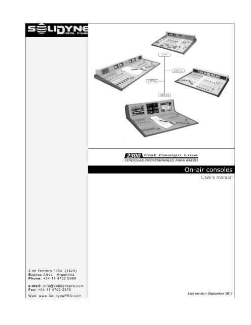
<strong>On</strong>-<strong>air</strong> <strong>consoles</strong>User’s manual3 de Febrero 325 4 ( 1429)Buen os Aires - ArgentinaPhone: +54 11 4702 0090e-mail: i nf o@solidyne pro.c omF ax: + 54 11 4702 237 5W eb: www .<strong>Solidyne</strong> PRO.c omLast revision: September 2012
Page 2 Broadcast mixing <strong>consoles</strong> - 2300 series SOLIDYNE
Table of Contents-Chapter 1Getting started........................................51.1 What’s in the box?.........................................51.2 Brief description............................................51.2.1 Inputs............................................................51.2.2 Output...........................................................51.2.3 DigiSolid Bus................................................51.2.4 Cue...............................................................51.2.5 VCA Operation..............................................61.2.6 <strong>On</strong>-Air Mics Button........................................61.3 Expansions & accessories...........................61.3.1 <strong>Solidyne</strong> 2300 series....................................61.3.2 VU and stereo phase vector.........................61.3.3 Timer / Clock................................................61.3.5 AES-3 outputs (AES/EBU)............................71.3.5.1 Connections.................................................................71.3.5.2 Settings........................................................................71.3.6 STUDIO BOX................................................81.3.6.1 Connections.................................................................81.3.6.2 Using the Studio Box...................................................8Chapter 2Installing and connecting .....................92.1 About installation..........................................92.1.1 Parasitic signals............................................92.1.2 RF interference.............................................92.2 Inputs & Outputs connections....................102.2.1 Rear Panel..................................................102.2.1.1 MONITOR OUTPUTS................................................102.2.1.2 HEADPHONES..........................................................102.2.1.4 STUDIO LIGHT (TALLY)...........................................112.2.1.5 CONNECTING THE TELEPHONE LINES................112.2.1.5.1 Connecting a cell phone.........................................112.2.1.6 Connecting an external Hybrid..................................112.2.2 INPUT MODULES......................................122.2.2.1 Line inputs..................................................................122.2.2.2 Digital inputs..............................................................122.2.2.3 Microphone inputs.....................................................122.2.2.4 Inserts........................................................................122.2.2.5 Digital control: DigiSolid in/out...................................122.2.3 Master Module............................................132.3 Connectors and wiring................................132.3.1 Line and Microphone connectors................132.3.2 MASTER 2307............................................142.3.2.1 Connector pin-out......................................................142.3.3 Wiring.........................................................152.3.3.1 Master 2307...............................................................152.3.3.22301 & 2320 Line modules.........................................152.3.3.2 2310 MIC Modules.....................................................162.3.4 Ground connections recommended forprotection against electric storms........................172.4 Customizing the modules...........................192.4.1 Using a mic into the Control Room.............192.4.2 48V Phantom power...................................192.4.3 Inserts.........................................................192.4.4Jumper’s description Table..........................202.4.5 Jumpers on Master Module........................212.4.5.1 Hybrid’s priority circuit................................................212.4.5.2 Mute the control room speakers ...............................212.4.5.3 External control of Master MIC button.......................222.5 Adding modules to console........................222.5.1 USB 2302...................................................222.5.2 2330 VQR module......................................222.6 Adjusting the input gains............................232.7 2300 XZ console – Installation....................252.7.1 LCD Displays..............................................252.7.2 Wiring.........................................................252.7.3 Mounting the rear panel..............................26Chapter 3Operation...............................................273.1 Introduction..................................................273.1.1 Checkout....................................................273.2 Master module.............................................273.2.1 Telephone line Mini-Central .......................273.2.1.1 Operation...................................................................273.2.1.2 HYBRID OUT.............................................................283.2.1.3 Using a cell phone.....................................................283.2.1.4 Hybrid rejection adjustment (NULL)..........................283.2.1.5 Make a conference on the Air....................................283.2.2 Master Module general description.............293.2.3 Monitors and headphones..........................303.2.4 CUE............................................................303.2.5 Master MIC button......................................303.2.6 Talkback.....................................................303.3 2310 Microphone module & 2301 Linemodule................................................................313.4 2312 Microphone Modules..........................323.5 2320 AES-3 digital module..........................333.5.1 Remote control...........................................333.5.2 Display information.....................................333.5.4 Programming the 2320...............................333.5.3 Operation....................................................343.6 2330 VQR Hybrid’s processor module.......353.6.1 Using the VQR............................................353.8 How to record with the 2300’s....................37SOLIDYNE Broadcast mixing <strong>consoles</strong> - 2300 series Page 3
3.8.1 Recording the Hybrid..................................37Maintenance..........................................394.1 <strong>On</strong> console’s temperature .............................394.2 Cleaning........................................................394.3 Preventive maintenance................................394.4 Parts Replacement........................................39Chapter 5Specifications & Measurements.........415.1 General Measurements...............................415.1.1 Microphone...................................................................415.1.2 Line...............................................................................415.1.3 Aux Input ......................................................................415.1.4 Balanced Outputs.........................................................415.1.5 Unbalanced Outputs ....................................................415.1.6 Gain..............................................................................415.1.7 Frequency Response....................................................415.1.8 Phase............................................................................425.1.9 Stereo Tracking............................................................425.1.10 Harmonic Distortion (THD).........................................425.1.11 Equivalent Input Noise................................................425.1.12 Signal/Noise ratio........................................................425.1.13 Crosstalk.....................................................................42Blocks diagram .................................................435.2.1 2310 MIC module.2 main channels for microphone..........................435.2.2 2312 MIC module.3 main channels for mic with processing.............44Master module. Model 2307..............................475.3 Specifications................................................49Page 4 Broadcast mixing <strong>consoles</strong> - 2300 series SOLIDYNE
CHAPTER 1Getting started1.1 What’s in the box?With the 2300 console, you will receive the followingitems:• This user’s manual.• 1 Interlock power cord.• A guaranty certificate.• If you don’t acquire the optional wiring kit, you receive aDB-25 connector for each module.• A tubular connector for ‘on the <strong>air</strong>’ lights (Tally).• 1 set of self-adhesive labels for channel identification.• 4 self-adhesive rubber supports.• 1 screwdriver for adjustment of gain presets.• 1 flat cable 2-pins to 2-pins for Pahntom 48V• 1 flat cable 2-pins to 3-pins for Mic “Mute “(Dj-speaker)• 1 spare parts kit (2 - TL074; 1 - TL072; 1 - CD4013; 1button MEC; 1 button MULTIMEC; 1 fader 10 K LIN; 1rotating fader 50 K LIN)• OPTIONALS• AIR Tally light• MNG2300 wiring kit• STUDIO BOX• MIC BOX (4 mic patchbay)1.2 Brief description1.2.1 InputsThe <strong>Solidyne</strong> 2300 <strong>consoles</strong> have a great flexibilitysince are fully modular. It allows to reconfigure the consolewithout leaving the <strong>air</strong>. The inputs modules aredouble. Each module has two faders of 100mm thatmanage two stereo signals, and each channel hastwo inputs (Line or Microphone and Auxiliary) commutablefrom a button in the front panel. There are differentmodels that manage different signals, that is:Microphone modules (2310 and 2312): The modules2310 manage two microphone channels (MIC) and twounbalanced line stereo inputs (AUX). The 2310 includespan-pot and a gain control with range of 30dB(+/- 15 dB) that allows to adjust the input levels forcomfortable operation of the main fader. They alsohave a 2 bands equalizer Baxandall type, with a rangeof +/- 15dB. The modules 2312 manage three microphonechannels and three unbalanced line inputs(AUX). It have the same features that the 2310 and includea stage of microphone processor with compressionand noise gate.Line modules (2301): Manage two balanced stereo inputs(LIN) and two unbalanced (AUX). Main and auxiliarygains can be adjusted using 4 presets located atthe panel, to match the levels of the different sources.Digital inputs (2320 and 2302): The modules 2320manage two digital inputs AES-3 and two analogicalunbalanced inputs (AUX). Each channel have an LCDthat shows the input level, assigned buses, selected input,and more. Modules 2302 offers direct connectionto the PC via USB. It works as external sound card, livingto the PC 2 playing devices and 2 recording devices(PGM and AUD can be recorder directly).1.2.2 OutputAll outputs are located on the Master 2307. Line andmicrophone modules have 3 stereo sends to the master:PGM (program), AUD (audition) and SEND.• The PROGRAM output is the main output, used to sendthe audio signal to the transmitter.• AUDITION is used to record or to hear audio in controlmonitors but not on the <strong>air</strong>.• SEND is a stereo bus. It’s used, by example, to make amix of all input channels, except the microphones. Thismix can be sent to the studio monitors. This way thespeakers will be able to listen a return in the loudspeakers,without necessity of headphones, still on the <strong>air</strong>.• The CUE bus allows hearing the signals with the channeloff and fader closed. The monaural audio will be listenedon the internal speaker, located at the right of themeter bridge. CUE can be assigned to the main monitorsof Control Room.1.2.3 DigiSolid BusEach channel has a DigiSolid Out control. This control(supported in all <strong>Solidyne</strong> equipment) allows controllingsatellite programs, the Audicom software, digital audioprocessors (VirtualRack), or to start others devices thatsupports remote control. The DigiSolid OUT is supportedin all modules. It activates when you open themain fader or press the AIR button on the channel. TheDigiSolid IN (only for modules 2320) is commandedfrom a PC via parallel port to turn on/off the input channelswith progressive fades digital controlled.1.2.4 CueWhen you press the CUE button, the signal present onthis channel is listened in the built-in speaker, wheneverthe channel is turning off or on the <strong>air</strong>. PressingCUE again the operation is canceled. If CUE is activatedin several channels, you will hear the sum of thesignals present in each module. The level is adjustedwith a CUE fader, located in the Master module.A button allows hearing the CUE in the main speakersof Control Room (and at the headphones).SOLIDYNE Broadcast mixing <strong>consoles</strong> - 2300 series Page 5
1.2.5 VCA OperationThe VCA (Voltage Controlled Amplifier) avoids audiosignal circulate trough the fader. The level is adjustedusing amplifiers of low noise and great stability. Thefader controls a DC signal that modifies the gain ofthese amplifiers. Main advantages of the VCA technologyare:• Eliminates the possibility of noise generated bydirty faders.• Eliminates the maintenance and cleaning of thefaders.• Maintains a perfect stereo tracking (error > 0,2 dB).• Allows the automation of the console from a computer.1.2.6 <strong>On</strong>-Air Mics ButtonLocated above the main fader in each input channel,this button sends the channel on the <strong>air</strong> when ispressed. Pressing it again the channel is turning off.This button lights when is on.The <strong>On</strong>-Air button is electronically activated using VCAtechnology; instead mechanical switching. It gives freeclicks and plops operation, due the fact that <strong>Solidyne</strong>uses a fast slope fading action instead of the hardswitch that other brands offer.When the console operates under PC control, AIR buttonis commanded from the PC.A master microphone button is located on the 2307Master module, which activates all microphones channelsat the same time. Or you can change, using internalsjumpers, the microphones that go to <strong>air</strong> in thesame batch. When the AIR button is on, turns on thetally light (the console gives 12 V DC as tally signal).Also, a relay is activated to mute the studio monitors.This modality allows an interesting facility; because youwill always use the MIC master button.1.3 Expansions & accessories1.3.1 <strong>Solidyne</strong> 2300 seriesAll <strong>Solidyne</strong> <strong>consoles</strong> can be customized according tothe requirements of your radio station. You decide howmany microphone and line modules will have your console.You can opt, also, to include other optional featuresthat are described next. The different models ofthe series 2300 are:• 2300 XS: It allows to house up to 12 channels (6 doublemodules), that can be microphone modules 2310/2312and line modules 2301. They have a Master 2307 and ameters panel with two needle VU-meters (Program). Optionallyit can include the VC180 option that is a displaywith Bar Graph LED true peak VU + Stereo Phase Vector;Clock & Timer and AES-3 digital outputs.• 2300 XL: It allows to house up to 16 channels (8 doublemodules 2301, 2320, 2310, 2312. Include a Master 2307and a meters panel with four needle VU-meters (Programand Audition). Optionally it can include the VC180 optionthat is a display with Bar Graph LED true peak VU +Stereo Phase Vector; Clock & Timer.• 2300 XX: has capacity for 26 channels (13 modules 2301,2310, 2320, 2312) or 16 channels with central desktop(width 400 mm). Incorporates a master 2307 and a meterspanel with four needle VU-meters (Program and Audition).Optionally it can include the VC180 option that is adisplay with Bar Graph LED true peak VU + Stereo PhaseVector; Clock & Timer and AES-3 digital outputs.• 2300 XZ: allows to house up to 26 channels (13 modules2301 / 2310 / 2320 / 2312), or 16 channels with centraldesktop (width 400 mm). Extended VU-meters panel with2 LCD flat screens (15”) video monitors. Usually has 3 xVC180 units, plus Timer1.3.2 VU and stereo phase vectorThe Stereo Phase Vectorallows measuring thestereo phase relationshipand therefore the gradeof stereo sensationachieved. The range is 0degrees (mono) to 90degrees (maximum stereo); with inverted phase indication(180 grades), to prevent to the operator that a connection’serror exists in the microphones, or amongequipment’s with analogical connectionsThe analogical section is gauged in steps of 20 degrees,with quadrant of vectors. This allows followingthe quick program variations. By other hand, the digitalsection retains for an instant the maximum valuereached by the phase rotation.A musical program with good stereo sensation willhave averages (analogic) of 40 to 60 degrees, withpeaks (digital) of 80 degrees. Readings of 0 and 20 almostindicate a monaural signal. The indication -0 orINVERTED implies the serious problem of invertedphase. This must be quickly corrected because the invertedsignals ‘disappear’ when they are listen in monoFM receivers.1.3.3 Timer / ClockThis panel (TM option)replaces the CUEspeaker, and it includesalso the speaker and anumeric display withtwo functions:a) Clock mode: provides the time while the microphonechannels are turned-off.b) Timer mode: shows a count up (minutes: seconds) whenthe microphones are on the <strong>air</strong>.Page 6 Broadcast mixing <strong>consoles</strong> - 2300 series SOLIDYNE
The timer mode is activated when the mics are activatedusing the Master <strong>On</strong>-Air button. When you turnoff the microphones, the time will be retained on screenby 3 sec and then the display will return to ‘clockmode’. If you turn on the microphones again (in this 3sec window) the timer will resume.Clock AdjustmentTo adjust the time there are three buttons: MODE, UPand DOWN. Pressing MODE button the adjustmentstarts. The less significant minute will blink. With Upand Down buttons, change the value. Pressing Modeagain you can change the most significant minute. Finally,pressing Mode again the hour character will blink.Modify the hour and press Mode to finish the time adjustment.1.3.5 AES-3 outputs (AES/EBU)Optionally, the Master 2307 can have AES-3 (akaAES/EBU) digital outputs for program and audition. Ifyou have an XL2300 with /2Dout option, the AES-3outputs comes from factory. This accessory (DG2300option) can be acquired later and added to the console.In this case you will install it like is described next.The optional DG2300 card will be fixed to the Masterback side, like shows the following figure. Turn off theconsole before the installation. Remove the fixationscrews of the Master, move away it carefully and placethe DG2300 card. Fix it whit the three screws like it isindicated in the figure. After fixing the DG2300, put theinterconnection cable. The connector only can be connectedin a unique position.DG2300 card1.3.5.1 ConnectionsThe AES/EBU (now named AES-3) output is balancedwith transformer. Use shielded twisted p<strong>air</strong> audio cablesto connect it. The connection to the Master moduleuses a DB-9 connector with the following distribution:DB-9 Connector 5 AUDITION AES-31 PGM AES-3 6 NC2 PGM AES-3 7 GND3 GND 8 GND4 AUDITION AES-3 9 NC1.3.5.2 SettingsSome parameters of the AES-3 protocol can bechanged with the jumpers located on the componentsside of the DG2300 card. Then, it will be necessary toremove the card from the panel, in order to modify thejumpers. The following figure shows the default positionof the jumpers.11.2896 crystal for Fs 44.100 HzDG2300 card (default configuration)DB-9 connectorFixation screwsJP2OFFCopyrightNormal operation (Factory)ONCopy Not allowed with copyrightLink ribbon cableJP6 JP7 EmphasisOFF ON Normal operation (default)ON ON EmphasisJP1 JP4 JX Sampling FsOFF ON 1-2 48 KHz (standard)ON OFF 2-3 44.1 KHz (*user modified)* to work with fs = 44.1 KHz, place a cristal of 11,2896 MHzwhere the above figure indicates.ON- AIR inputFig. 1 - Rear view of the Master 2307 with the optional card DG2300‘Copyright', ‘Emphasis' and sample rate (Fs) configurationsare the same ones for Program and Audition.The jumper JX is common for both outputs. The nonmentioned jumpers (JD-AUD and JD-PRG) must remainunchanged.SOLIDYNE Broadcast mixing <strong>consoles</strong> - 2300 series Page 7
1.3.6 STUDIO BOXStudio Box is an optional accessory which concentratesin a unique box all monitoring facilities into theStudio. Studio Box offers the following features:• 5 headphones outputs with independent control level.• Output (line level) for Studio Monitors with level control.• Tally• Timer / Clock• Talkback, to talk with the Control Room operator.MIC GAINMIC (to control room)1.3.6.2 Using the Studio Box<strong>On</strong> the Studio HeadphonesAlthough each headphone has its control of level; themaximum level is determined by the console. As youcan suppose, which listening is also depended on theselection done in console.<strong>On</strong> the Studio MonitorsLike happens with the headphones, the loudspeakersoutput has level control, but the maximum level andwhat you hear is depended on the console.If the loudspeakers are connected directly to the console’sspeaker outs; “Loudspeaker” doesn’t take effect.Usually the Studio Box is placed on the table; but agood choice is fix them to the wall when the table isnext to the Control-Studio window.1.3.6.1 ConnectionsStudio Box connects to the <strong>Solidyne</strong> 2300 console usingonly one cable. This cable is female DB-9 to maleDB-9 pin-to-pin (NOT crossed), and is provided withthe unit (5 M length).Through this cable the console sends to the Studiothe monitoring signals for headphones and loudspeakers.Headphone outputs use ¼” stereo TRS (jacks). Anycombination of headphones can be used (16; 32 and64 ohms).Loudspeakers output use a 1/8” stereo TRS (minijack).This is a line level output, so you must usepowered speakers for the Studio. If you have conventionalloudspeakers, you can use the amplified outputof the console instead the monitors output of the StudioBox. In this case the volume could be controlledonly by the operator from the console<strong>On</strong> the Studio TalkbackThe white button has two functions:1.- When the microphones off-<strong>air</strong>, press the buttonto speak to the Control Room. The Studio Box has abuilt-in microphone for this purpose.At the Control Room, the operator will hear you directlyby the Left loudspeaker. The volume is fixed,independent from the loudspeakers knob of the console(Studio Box has a MIC Gain preset, accessiblefrom the frontal panel). To answer, the operator willuse the Talkback of the console.2.- Being on-the-<strong>air</strong>, the white button illuminates in redindicating that microphones are “on-<strong>air</strong>”. Obviously, inthis condition Talkback feature is disabled.The preset located below the MIC allows to adjust the microphonegain, so it adjust the listening level on the ControlRoom.<strong>On</strong> Timer / ClockThe display shows the current time (off-<strong>air</strong>) or the timelapsed on <strong>air</strong> (when microphones activates). Thisfunction operates like the accessory TIMER for 2300<strong>consoles</strong>. Please see 1.4.3 – Timer / Clock for details.An additional option respect to the accessory TM inconsole is that the “counter mode” can be disabled;quitting an internal jumper. Open the back cover of theStudio Box and to retire the jumper. There is a uniquejumper available. This will always deactivate the on-<strong>air</strong>lapsed time counter, being always the time on display.Page 8 Broadcast mixing <strong>consoles</strong> - 2300 series SOLIDYNE
CHAPTER 22.1 About installationInstallation of <strong>Solidyne</strong> audio console doesn’t presentparticular problems. However, keep in mind the basicrules for all professional audio installations. The inputsand outputs of the 2300 series incorporate DB-25multi-pin connectors. You can acquire the <strong>Solidyne</strong>connection’s kit (MNG2300), which incorporate mostof basics connections for the radio equipment, so youonly will make some few connections.All balanced connections will be made using doubleshielded cable. Use only good quality audio cables.The high-level unbalanced inputs and outputs can bewired using shielded cable. For loudspeakers outputs,use cable with 2 mm2 section. The microphone andloudspeaker cables will take separated paths.If you use a microphone connector’s box, it will becompletely shielded and connected to a good ground(the same ground that the console).To avoid loops grounds, that can produce hum and noise,don’t connect the audio GND with the AC ground. This connectionis carrying out only by the third pin of the power supplycord.2.1.1 Parasitic signalsGenerally, are considerate parasitic signals all unwanted signalsthat appear in audio lines. A common type are denominated humming,low frequency signals (multiples of 50/60 Hertz) caused bythe interaction of electromagnetic fields coming from the AC line.When the interference source is a magnetic field (generally originatedin a supply transformer) the resultant interference will bedenominated electromagnetic humming. When the interference isdue to such electric potentials as cables that take supply tensions,that are elevated in comparison with the audio signals present inthe circuit, you will be in presence of electrostatic humming. Thedistinction is not merely academic, because the resolution of aproblem supposes the knowledge of the noise type to apply thecorrect solution.Examples: To minimize the reception of electromagnetic humming in thewires, remember the following rule: "THE AREA AMONG TWO AUDIOWIRES WILL BE MINIMUM." It implies that the cables will be tied veryclose, like the shielded twisted p<strong>air</strong> audio cables. They should pass faraway from any transformer or devices that manage high-intensity currents.Is important to remember that a wire can be good shielded, but ifhis conductors don’t complete the conditions of minimum area it will besusceptible to take magnetic humming.Installing and connectingOther parasitic signals are: AC HUM, RADIO FREQUENCY andCROSSTALK. As hum noises like the radio frequency are originatedby electromagnetic fields of high frequency; the first onesare originated by disturbances due to the connection and disconnectionof equipment’s to the AC line, the seconds ones are generatedby communications transmitters or industrial equipment. Ifthese signals penetrate into audio lines, with sufficient intensity,can surpass the action of the special protection filters, and toreach some sensible part of the input stages. In that case, the interferingsignals can be demodulated and already turned audiosignal, and will be amplified by the rest of the system. It is fundamental,therefore, to maintain the interference within reduced margins.It is obtained avoiding very long audio lines, with aerial sectionsor that pass near of transformers or RF transmitters. For protectionagainst very high frequencies is advisable to use doubleshielded cables, guarantied by the manufacturerCROSSTALK is the reception of signals coming from other linesof audio. This, like all unwanted noise, it can be supposed controlledwhen its level is below the level of the system residualnoise. Then, all considerations mentioned for the case of buzz arevalid.2.1.2 RF interference2300 <strong>consoles</strong> have numerous internal protections against RFfields, for the AM and FM broadcasting band. When the transmissionstation is installed correctly, there will be no interferenceproblems, still with FM equipment of 50 kW installed in the terraceof the radio station. Nevertheless, when the antenna is badly positionedwith respect to the Studio or has severe SWR problems,then it does not have the minimum value of field intensity, downward.Or maybe there is a faulty ground connection, then, strongstanding waves will appear on the cables of the Studio that can inducehigh electrical currents inside the audio console.Symptoms: If the interference takes place at the A.M. band, thesound transmitted by the A.M. radio will be listened in the loudspeakerson background (or at buses PGM, AUD or SEND). Incase of FM transmissions, the interference inside the console demodulatesthe A.M component of the FM carrier; (usually humfrom power supply) causing background humming, because inmany transmitters of FM, the final output stage is not poweredwith stabilized tension. Therefore, if console 2300 presents humming,please make a test shutting down the transmitter a few secondsto check if the problem disappears. Sometimes, an FMtransmitter with the output stage badly calibrated also produce interferencein which you can hear the transmitted audio (due to themisalignment a part of the FM modulation is translated to AMmodulation).Solution: 2300 <strong>consoles</strong> already have internal filters to avoid theRF interference. Therefore, if interference’s appears, normally iscaused by installation problems on the transmission station thatgenerate elevated currents in the wiring of audio on the Studies,due to the standing waves. These currents circulates inside thecabinet of the 2300, and enters to the console when overpass thebarriers that impose to this currents the built-in RF filters. The solution,then, must be external to the console.The solution is to acquire ferrite O-rings of 60 mm diameter, toallow passing the cables and connectors. They will be used ineach one of the D25 connectors, in the inputs and outputs. The totalset of cables that goes to each connector, will have to betwisted with a complete return around the ring (see 2.3.3 - Wiring).SOLIDYNE Broadcast mixing <strong>consoles</strong> - 2300 series Page 9
2.2 Inputs & Outputs connections2.2.1 Rear PanelFig.3a Rear panel– power sourceFig.3b Rear panel– connectorsLooking the console back side, you will find at the leftside the power on/off switch, the main fuse (1 Amp)and the AC connector for Interlock power-cord (providedwith the unit). Near to the AC interlock, there isa voltage selector (220/110 VAC).To access to this board you must remove the backpanel of the console. To disable the amplification forStudio loudspeakers, quit the jumpers J15 and J16.To disable the amplification for Control loudspeakers,quit the jumpers J18 y J20. See next image:BEFORE CONNECT THE UNIT TO THE POWER LINE,CHECK THE 110 / 220 VAC SELECTORThe rear panel also contains the connectors for theloudspeakers monitors, headphones, and telephonelines with their associate telephone set and on-<strong>air</strong> lightoutput (tally).All inputs connectors are multi-pin DB-25 type, locatedunder the rear panel. Remember: good connectionsbetween the console and audio equipment are veryimportant question to guaranty a sure and free offlaws operation. For that, we recommend you take thenecessary time to carry out the wiring of the console,with a great care and always using high quality components.A good solution is to acquire the connection’scables kit, accessory <strong>Solidyne</strong> MNG2300.2.2.1.1 MONITOR OUTPUTSThe STUDIO and CONTROL ROOM outputs are powered,so you can directly connect the loudspeakers (4– 8 Ohms) The internal stereo amplifiers gives 15WRMS power (7,5W + 7,5W). Amplification can be disabledby jumper to change the outputs to line level inorder to use active speakers. There are two jumpersfor Studio outs and two for Control Room outs.The loudspeaker DC resistance is very near to the nominalimpedance, For this reason, we recommend previous to theinstallation, to measure with a tester the resistance thatpresents the loudspeaker and to discard all the units that hasn value smaller than 3 Ohms.Loudspeakers outputs use ‘RCA’ phono connectors. Takecare with polarity. If loudspeakers work with inverted phase, itcan cause remarkable lost at low frequencies.2.2.1.2 HEADPHONESThere are independent outputs for STUDIO and CON-TROL ROOM, with ¼” jacks connectors. STUDIO outputallows to connect up to 8 headphones, whereasthe CONTROL ROOM output supports up to 2 head-Page 10 Broadcast mixing <strong>consoles</strong> - 2300 series SOLIDYNE
phones. Headphone outputs are protected against accidentalshort circuits.At the console, the operator has independent levelcontrols for Studio and Control headphones. Into theStudio is convenient to install the <strong>Solidyne</strong> Studio Boxheadphones distributor. This unit is placed on the tableand brings up to 5 headphones with its volumecontrol.2.2.1.4 STUDIO LIGHT (TALLY)The STUDIO LIGHT output gives 12 volts / 0,3 A whenthe studio microphones are activated. This allows activatingLED’s <strong>On</strong>-Air lights that are highly reliable and don'tneed replacement as the systems of incandescent lightdoes. The <strong>Solidyne</strong> “<strong>On</strong>-Air Light” kit, with characters 100mm high, is a professional solution.You need a special cable RJ-11 whose connection willdepend on the brand and model of your cell phone.You will need to purchase the “free hands” accessory correspondentto your cellular and to consult the documentationof the unit to make the connection (see the next image).Basically, which transmits the cell phone through the “freehands” connector is the audio signal of the cell telephone:microphone and loudspeaker. The HA-202/204 receives,via cell phone, the remote audio (that is to say, the audioof who is at the other side of the line). <strong>On</strong> the other hand,the hybrid sends to the cell phone the audio from the studiesof the radio (return signal).Usually, microphone and loudspeaker of the cell phoneare disconnected while “hands free” connector is used.2.2.1.5 CONNECTING THE TELEPHONE LINESThe Hybrid 2307 manages 2 telephone lines and 1 cellphone input. It has internal precision adjustments factorycalibrated. So user adjustments don’t be required. <strong>On</strong>lythe rejection factor must be re-adjusted to be adapted tothe local telephone line (please see 3.2.1 – Hybrid 2307)In the rear panel there are 5 connectors RJ11 type. Twoare telephone lines inputs; two are for connecting the associatedtelephone sets (Production Phones) and the fifthis the cell phone input.The lines can be connected directly to the internal radiotelephone PBX system instead to the public switch. Ofcourse the radio station can connect it to public switching.The hybrid inputs have internal filters for RF rejection, effectivein AM, FM and UHF bands. Usually isn’t necessaryto add additional filter. The telephone lines have internalhigh tension protection using Metal Oxide Varistors. Butwe recommend having additionally a good external protection.Phone lines protectionThe telephone lines will always have protection againstlightning and electrical surges. Please, see general protectiondiagram at the end of this chapter.2.2.1.5.1 Connecting a cell phoneCell phone connects directly to “CELL” RJ-11. An adaptationcable is required for connect the cell phone to theconsole, that defers according to mark and model fromthe cellular. The cellular connects to the hybrid using the“free hands” connection that the cell phones have.Consult with his <strong>Solidyne</strong> dealer by this accessory. Formake this yourself, please read the following indications.2.2.1.6 Connecting an external HybridSeries 2300 have SEND and RETURN connections forexternal Hybrid trough ¼” Jack located on rear panel (alsoavailable in pins 13 and 15 of DB-25 Master connector).This send is Mix-minus, that to say, it includes all the signalsof the PGM Bus, with exception of the Return fromHybrid, to avoid a feedback loop.The signal the incomes by the external hybrid’s return, isrouted through the same control circuit that the signals ofthe internal hybrid. Therefore the Hybrid fader control willbehave in the same way that it works with the telephonelines connected to the console, sending the signal to the<strong>air</strong> or to CUE, according to the fader position. When youconnect an external hybrid, the internal hybrid of the consoleremains active and can be used independently of externalhybrid.You can conference between the lines connected to consoleand the hybrid content. Remember: once a call is on<strong>air</strong>, the Hybrid cue channel is disconnected, so you mustuse a phone associated with that line to speak privatelywith the second call.SOLIDYNE Broadcast mixing <strong>consoles</strong> - 2300 series Page 11
When a conference between internal and external hybridare made, take care with the output level at the externalhybrid, so an excessive level can cause feedbacks.2.2.2 INPUT MODULES2.2.2.1 Line inputsAll line inputs are stereo, electronically balanced (transformerless).It allows the connection of high-level signalsbalanced or unbalanced. Input gain adjusts from thefrontal panel with the GAIN LINE presets (L & R). In orderto unbalance this inputs, connect the negative (-) pin toGND and positive pin to signal (see 2.2.4 – “Connectionstables”).AUX inputs are unbalanced stereo. It manages -10dBu /10KOhms and +4/+8 dBu line levels. Input gain adjustsfrom the frontal panel with the GAIN AUX presets (L&R).The LINE and AUX input impedance is bigger than 10Kohms (Bridging inputs). This is compatible with all currentequipment (sound cards, CD-player, etc.). But if youneed to adapt the input to 600 ohms, place inside the connectora 680 ohms resistor in parallel with the input.2.2.2.2 Digital inputs2300 console's can have AES-3 inputs (modules 2320)which also supports SPDIF signals; and direct USB connectionto computer (modules 2302).• To known about AES connecting please refers to“2.3.1.1 – 2320 AES-3”• To known about USB connecting please see“2.3.1.2 – 2302 USB”.• To know the use of AES-3 module 2320 pleasesee “3.5 – 2320 AES-3 digital module”2.2.2.3 Microphone inputsMicrophone inputs are electronically balanced. Gain adjustsfrom the frontal panel with a preset control with30dB of range. The pan-pot allows change the microphoneposition in the stereo image. AUX inputs are similarto line modules, but they don't have gain presets. The DB-25 connector has the same pin-out that the line inputsconnectors. Please see connections at 2.3 ‘Connectionsand wiring’.2.2.2.4 InsertsMicrophone modules have insert connections in both microphonechannels (MIC-A and MIC-B), while the linemodules only have a stereo insert for the LINE A.Through the insert connection, the console sends audio toa external processor (i.e. a compressor). The processedsignal returns to the microphone module to be mixed inthe console. That is to say that the processor is connectedin series to the input of the module, therefore, if the processoris power off or disconnected, there won't be audiosignal in the module input.In order to use the inserts, remove the 'jumpers' JF8 andJF9 in the module. This jumper connects the send (SND)with return (RTN) when there aren’t insert connection.(See 2.4 – ‘Customizing the modules’). The connection isdetailed in 2.3.1 – ‘Line and microphone connectors’.2.2.2.5 Digital control: DigiSolid in/outEach module has a connector to send 'DigiSolid' controlsignals. When you open the main fader, the 'DigiSolid-Out' activates, starting devices like the Audicom system,<strong>Solidyne</strong> 262 digital audio processors, CD or Mini-discplayers, etc.DigiSolid-Out uses an open collector circuit; with the faderclosed the output presents an open circuit. When youopen the fader, the circuit closes. It can manage until+24V, 100mA. In the 2301, 2310 and 2312 modules, theDigiSolid-Out connector is located under the module, onthe circuit board, for that, you must to move away themodule in order to connect it (see 2.4 – ‘Customizing themodules’).DigiSolid out uses a 3-pins polarized connectorwhose location and connections arethe same for 2301, 2310 and 2312 modules.1 = DigiSolid - Out A 2 = GND 3 = DigiSolid-Out BModules 2312 has a third DigiSolid connector for the channel“C”. see diagram in 2.4 – ‘Customizing the modules’In the 2320 digital module the DigiSolid connector locatesat the back side of the module, beside the DB-25. Is a 5-pines polarized connector that includes a DigiSolid input,which allows to control the 2300 channels from the Audicomcomputer (via parallel port), enabling the inputs bythe automation software to control, for example, Satelliteprograms. The distribution is indicated in the next table:2320 DigiSolid Connector1 Out B4 Out A3 GND2 In B 5 In AThis connectors are provided with the 2320 modules.DigiSolid inputs of channels A and B can be connected inparallel mode, in order to command both channels with anonly control signal. The channels will be programmed sothat when receiving the DigiSolid control signal, a channelis activated increasing its level progressively, while theother one will fading until zero, achieving this way an perfectautomatic cross fade. Different attenuation slopes anddelay times can be programmed (see 3.4 – ‘2320 digitalline modules’).Please refers to the documentation of your on-<strong>air</strong> assistantsoftware to know where to connect the digiSolid inputs.It varies on each system (Audicom uses an USBport).Page 12 Broadcast mixing <strong>consoles</strong> - 2300 series SOLIDYNE
2.2.3 Master ModuleThe main output connector is a multi-pin DB25 type.Optionally, you can require a complete connections kit<strong>Solidyne</strong> MNG2300 that includes all standard cables andconnectors for inputs and outputs. PGM and AUD outputsare electronically balanced, with a high reject commonmode signals. SEND output is unbalanced stereo. To unbalancea balanced output, only connect the positive pin(+), and leave unconnected the negative one (-).The nominal output level is: 0 VU = +4 dBm. When abalanced output is connected to unbalanced inputs, itslevel is reduced in 6 dB, therefore 0 VU= -2 dBm. Noticethat if some nonprofessional equipment is connected tothe 2300 output, possibly the level will be too high andsome clipping will occur. In this cases use a fixed fader toreduce the level.ON-AIR input: Next to the main DB-25 connector there isan 1/8” jack (see page 7 fig.1). This is a stereo input toconnect an external tuner. Both Studio and ControlRoom monitoring must be done hearing the on-<strong>air</strong> signal.Use professional tuners with outputs of low impedance(600 Ohms). In case of use consumer tuners, you must adda line amplifier between the tuner outputs and the “Air” inputof Master 2307. This line amplifier is for adapt the tuner outputto low impedance.CUE input: Master 2307 have a CUE input, designed toconnect the monitoring output of the computer. This wayyou don’t’ need to use additional speakers next to thecomputer. CUE input is available at DB-25 main connector(pin 23).2.3 Connectors and wiring2.3.1 Line and Microphone connectors Note: In the 2312 modules, right connector corresponds to the channels A and B; and the left one to the channel C (viewing the console from rear).2.3.1.1 2320 AES-3Modules 2320 use for the AES-3 connection the same pinsused for AUX inputs in modules 2301 and 2310 (see“2.3.3.2 2301 and 2320 line modules”)5 and 6 signal18 ground for channel A8 and 9 signal21 ground for channel BThis means that the cables of modules 2301 and 2320 arecompatible. The cables that are AUX inputs entered for first;for the second are AES-3 inputs. Remember that to be adigital signal both channels by an only balanced cable aretransmitted.You can enter to the AES-3 input with S/PDIF, connectingsignal S/PDIF to terminal 2 of the XLR and the shield to terminals1 and 3.2.3.1.2 2301 USBThe 2302 module connects directly to the computer viaUSB. Each channel is recognized by Windows© as USB externalsound card. In this way, the audio is send directlyfrom the computer to the console, without leave the digitaldomain.In addition, the 2302 provides two analogical balancedauxiliary inputs. Balanced inputs are available on DB25connector, and are wired like the balanced inputs of module2301 (please refers to “2.3.3.2 – 2301 & 2320 linemodules”).SOLIDYNE Broadcast mixing <strong>consoles</strong> - 2300 series Page 13
Each USB channel is independent and can connect tothe same computer or two different computers. Bothchannels are compatible with USB 1.1 and 2.0.ATTENTIONBefore connecting the USB port of the console to your PC,make sure that both the console and the PC have a groundthrough its power cords. To be safe, connect one tester in the range of25 VAC between the chassis of the PC and console and check thatthe voltage is zero volts. <strong>On</strong>ly then connect the USB cable. OfDoing so may damage the USB port of your console or PC.Connect the 2302 module to any USB port of a computerrunning Windows©. When connecting it, Windows©recognizes the 2302 and install the drivers.Additional drivers are not required. Each channel appearson Windows like one stereo USB playing deviceand one stereo recording device.When you plug a channel, the display on the modulewill show “PC4” indicating that one stereo play channeland one stereo recording channel are active. If thesecond channel is connected, the display will changeto “PC8”; indicating that the eight channels were recognized(2 stereo outputs and 2 stereo inputs).You can check the available sound devices from“Control Panel > Sound devices > Audio”. In this Window’spanel you can set the default sound devices.Remember to update the settings on your recordingand on-<strong>air</strong> software.We recommend do not change the USB cable conection toother USB ports, to avoid that Windows change the order ofUSB devices.ATTENTIONWindows XP: Check the output level in the Windows mixer ("Programs→ Accessories → Entertainment → Volume Control").Windows 7: Verify that the OS has correctly recognized the audiorecording device. If Windows 7 was recognized incorrectly as "microphonedevice", the recordings will be mono (the same signal in bothchannels). To correct this: Control Panel → Sound → Record →choose the USB device (shown as USB microphone) and click [Properties].Then select the tab "Advanced", display the menu of formattingoptions and choose a format recording stereo (2 channels, 16bits, 44100Hz).Before connecting the USB port of the console to the PC make surethat both the console and the PC have an effective ground by cables.For safety,connect a tester in the range of 25VAC between the chassisof the PC and console and verify that the voltage is zero. <strong>On</strong>ly thenconnect the USB. If there are differences of tension, the USB input onthe console or your PC may be damaged.In addition, module 2302 offers two digital USBsends that appears at Windows like “USB recordingdevices”. 2302 Channel-A gives the program signal(PGM) and the 2302 Channel-B sends the Auditionsignal (AUD). The USB PGM out can be used, for example,to web-casting.The level of USB signal is set according to the standard K-15. The 0 VU (+4 dBu) corresponds to -15 dBfs at USB digitaloutput. There are 15 dB of headroom before clipping(above +4 dBu). Note that the ballistics of the needle VUmetershows the average level (do not show instantaneouspeaks), while the LED displays VC180's shows the truepeak level, being the full scale 0 dBfs.2.3.2 MASTER 23072.3.2.1 Connector pin-out1, 2 Left balanced PGM output 22 GND14 GND 23 CUE INPUT (PC Cue)3, 4 Right balanced PGM output 11 Mono PGM output16 GND 12 GND5, 6 Left balanced AUD output 13 PGM out (send) to external hybrid18 GND 15 Input for External Hybrid return7, 8 Right balanced AUD output 17 No connected20 GND 19 EXT – L IN9 SEND L 21 EXT – R IN10 SEND R 24, 25 GND The Pin number that appears in first is thepositive (+). The pin number that appears first is thepositive (+) The 0VU reference is +4 dBm. To unbalance an output, leave unconnectedthe negative pin (never connect it to ground).Page 14 Broadcast mixing <strong>consoles</strong> - 2300 series SOLIDYNE
2.3.3 Wiring2.3.3.1 Master 23072.3.3.2 2301 & 2320 Line modulesThe cable for AES-3 2320 module is similar to the shown one above, except for the AUX inputs that corresponds to the AES/EBUinputs (See 2.3.1). AES/EBU inputs typically uses female XLR connectors.Analogical balanced inputs for the USB 2302 modules are wired like balanced inputs of 2301 modules.SOLIDYNE Broadcast mixing <strong>consoles</strong> - 2300 series Page 15
2.3.3.2 2310 MIC ModulesNOTE: If you hear background hum, it can be produced by RF stationarywaves, induced from the FM antenna. In this case, you mustinstall ferrite o-rings (60mm diameter) in all input & output cableslike shows the left image (see 2.1.2 – RF interference).For use the INSERTS CONNECTIONS, you must remove the jumpers JF8 y JF9 from the correspondent module, as is indicated in 2.4 –Customizing modules.Page 16 Broadcast mixing <strong>consoles</strong> - 2300 series SOLIDYNE
2.3.4 Ground connections recommended for protection against electric storms.SOLIDYNE Broadcast mixing <strong>consoles</strong> - 2300 series Page 17
Schematic Diagram – Recommended connection of 2300 <strong>consoles</strong>Page 18 Broadcast mixing <strong>consoles</strong> - 2300 series SOLIDYNE
2.4 Customizing the modulesAccording to the connections and use, some console'smodules can require a customized configuration.2.4.1 Using a mic into the Control RoomThere are three features that must be changed to beable to use with comfort a microphone at the ControlRoom:a) Unlink the channel from the “Master Mic” button.b) Enable the MUTING for Control Room monitors.c) Disable the talkback “auto-cue” for this channel.connected without problems to a phantom poweredchannel, since this kind of microphones are designedso that they operate without the phantom voltage affectsthem, because the DC never pass trough the coil.To enable the 48V phantom voltage, remove the therear panel and locate the connectors J1 y J2 showedin the figure. You can connect up to two MIC modules(3210 or 2312).To avoid risk of electric shock, shut down the console and unplugit from the AC outlet before remove the rear panelBy default, all microphone modules are turned-on whenmaster MIC button is pressed, but this feature can bedisabled by jumper (JA) for each channel. That’s veryuseful for Dj’s who talk’s on-the-<strong>air</strong> from the controlroom. In this case, the microphone located in the controlroom will not be activated by the Master button (toavoid accidental loopbacks if this fader is open).Radios in which studio and control are the same room can connectthe monitors directly to “Studio speakers” output.For make this, remove the JA jumper (“a”, “b” or “c”according to the channel). This way, you can turn-onthe control room microphone only by pressing ON buttonon this channel.<strong>On</strong> the other hand, you can configure the channel, sowhen you turn-on this microphone, the speakersmonitors at the Control Room are muted to avoidfeedbacks. For this feature, you need to connect theDigi-Solid out of the MIC channel (DG-AB connector,see Digi-Solid, 2.2.4) to the MUTE input at the Mastermodule. Quit the Master and locate a 2-pins connectorlabeled MUTE. To connect it, you need the special flatcable (2-pins to 3-pins) provided with the console (seepage 14 for details).Finally, is possible to disable the “auto-cue” featurethat allows cueing the microphones after pressing theTalkback button. For make this; quit the jumperJcue’a or Jcue’b according to corresponds.2.4.2 48V Phantom powerBuilt-in 48V phantom powering is standard in series"X" (XL, XX, etc.). It allows to obtain a phantom voltageof 48 volts on up to 6 microphone inputs (2 x2312 modules), and enables them to operate withcondenser microphones.When a 2300’s MIC module connects to the phantomvoltage, the voltage is applied to all channels of thesemodule. Conventional dynamic microphones can beUse the connection cable provided with the console (2-pin polarized connector at both ends, connectedCROSSED) to connect the phantom voltage output (J1or J2) to the microphone module; quitting JPH1 jumperand plugging the cable there (see the following table).REMEMBERWhen a microphone module is connected to the phantom power supply,the phantom voltage applies to all channels of this module.Conventional dynamic microphones can be connected without problemsto a phantom powered channel, since dynamic microphones are designedso that they are not affected by phantom power supply.2.4.3 InsertsMicrophone and line modules have insertion points,which must be enabled by jumpers (JI open) to beused. When inserts are enabled, you will not have audiosignal in the module until equipment is connected(e.g. a compressor) to the insertion send / return.Next table describe all configurations including theDigi-Solid out connections (the DigiSolid connectionsfor digital modules 2320 are explained in 3.5 - 2320Digital line module). Obviously, it will be necessary toretire the modules of the cabinet to carry out thechanges. Normally, you don’t need to turn-off the console.SOLIDYNE Broadcast mixing <strong>consoles</strong> - 2300 series Page 19
2.4.4 Jumper’s description TableMOD. JUMPER DESCRIPTION STATE CHANNEL23102312231023122310JPH1JPH2JE’aJE’b2310 JA’a JA’b (**)2312231023122301231023122301JA’a JA’bJA’cJI’aJI’bEnables Phantom-power:12V provided by moduleor 48V internal power supply.12V Phantom-power sent toMIC modulesBypass EQModule activation from MasterAIR buttonEnable insertsEnable insertsFor 48V: Quit the jumper and connect here the 48V phantomcable. Notice that JPH2 must be open (see below).For 12V: Quit the jumper from JPH1 and put it on JPH2.When the phantom-power isn’t used, a jumper will have to beplaced on JPH1 (default).Disabled from factory (Jumper OFF). To enable the 12V phantom-power,quit the jumper from JPH1 and put it on JPH2.Never leave both jumpers ON.If 48V phantom power is present, leave JPH2 open.Jumper 1-2 = EQ disable (by-pass).Jumper 2-3 = EQ enableON = Commutable from Master (default)OFF = Commutable only from MIC moduleJumper ON by default. Remove it for use insertions.In line modules, enables the insert for left chnl of LINE A.Jumper ON by default. Remove it for use inserts.In line modules, enable the insert for right chnl of LINE A.AllAllSee last letterof jumper nameSee last letterof jumper nameMIC ALine A - LeftMIC BLine A - Right2312 JI’c Enable inserts Jumper ON by default. Remove it for use inserts. MIC C231223012302231023122301Jcue’aJcue’bJcue’cSTARTDisconnect CUE of the Autoswitch(Talkback)Force the channel A to ON-AIR when the console ispower-on.Jumper ON = auto switch enabledJumper OFF = auto switch disabledDisable by default (2-3), both channels remain OFF when theconsole starts. To enable it, change the jumper to pins 1-2:'Channel A' will turned on when the console is turned-on.See last letterof jumpernameDG-AB DigiSolid-OUT (refers to 2.2.4) 1=DigiSolid A 2=GND 3=DigiSolid B A / B2312 DG-C DigiSolid-OUT 1=DigiSolid Out 2=GND 3=Unconnected CALine modules only have two jumpers, which must be out when the INSERT is used.Fig.11 - Microphone module 2312 (welds side)Page 20 Broadcast mixing <strong>consoles</strong> - 2300 series SOLIDYNE
Fig.12 - Microphone module 2310 (welds side)Fig. 13 - Line module 2301 (welds side)Fig. 14 - Line module 2302 (welds side)2.4.5 Jumpers on Master Module2.4.5.1 Hybrid’s priority circuitThe circuit of priority of the hybrid attenuates the audiocoming from the telephone line when the studiospeaker speaks. This is thus to give priority to thespeaker in a debate (when both speak simultaneously,the speaker is listened on whom calls) and toimprove the audio quality of the local voice.In some uses, like sport transmissions, this effect isundesired (it is not desired to attenuate the atmosphereof the stage when the speaker from studiesreads an announcement). The priority can be disabledquitting the jumper JPRIORITY located in Mastercircuit board.2.4.5.2 Mute the control room speakersWhen microphones in the control room are used, theloudspeakers must silence when activating these microphones,in the same way that happen in thestudy, to avoid feedback.This is obtained connecting cable “MUTE” providedwith the console; that connects MUTE of the Master(2 pins) with the microphone module (3 pins) usedinto the Control Room.By default, the loudspeakers are silenced by the activationof the MIC-A. So that the loudspeakers bemuted by channel B; change in the 3-pin connectorthe pin 1 to pin 3 (removing and changing the inter-SOLIDYNE Broadcast mixing <strong>consoles</strong> - 2300 series Page 21
nal contact). You can joint 1 to 3 to mute the loudspeakersusing A or B channels indifferently.2.4.5.3 External control of Master MIC buttonConnector EXT MIC CONTROL allows to turn-on remotelythe “Masters MIC” button. By the other hand,sends a positive voltage when Masters MIC button isON.“Master MIC” can be turned-on from outside joiningterminals 3 and 4 of this connector (for example usinga relay). When the Masters MIC button is on,there are 15 VCC in pin 1 of the connector.1 OUT 15 V (Master Mic pressed)2 GND3MASTER MIC ON (joint to turn-on)4VQRCONTROL ROOM MUTING...to mic module (3-pins DG-ABconnector)At the moduleThe fig.14 (see 2.4.2 – Jumpers on the modules...)shows the 2302 module circuit board side. The connectorlabeled 'JD' must beconnected to the Masterwith the ribbon cable supplied with the module.When you screw the module, be sure to attach thelock washers (star washers) in the top screws of themodule, as these washers ensure electrical continuitybetween the plate of the module and the consolecabinet. You can use the washers removed from theblind panel or replace new washers.At the 2307 MasterYou must remove the Master module to connect theribon cable; but you don't need to unplug the Master.Locate the 10-pin connector 'JD' and plug in the ribboncable.When replacing the Master module into her position,be sure to attach the lock washers (star washers) inthe top screws of the module. These washers ensureelectrical continuity between the plate of the moduleand the console cabinet.Fig. 15 - Master 2307 – circuit board view2.5 Adding modules to console2.5.1 USB 2302The USB 2302 digital module requires connection tothe 2307 Master module, to enable the recording onthe PC of Audition and Program signals. When youbuy this module separately, you receive a ribbon cablewith 10-way connector pins.If you do not connect the ribbon cable to the Master, the 2302module works well , but only as playing device. When connectsthe USB cable, the module is detected by Windows andthe USB devices will be available, but if you try to record audio,the computer will record silence.2.5.2 2330 VQR moduleThis optional module adds to the console a processingstage for improve the audio quality of telephoniccommunications. If you acquire this optional moduleafter purchase the console, proceed as follow tomount it into the console.The 2330 VQR requires one simple-module spaceavailable in the mainframe (it has the same wide of a2310 module)Since it requires connection to the 2307 Master module,must be placed beside the Master.If your console does not have free space next to theMaster, considers moving all the modules that arenecessary to leave a place beside the Master. Iseasy to do it since the modules are interconnectedby a ribon cable with polarized connectors. In orderto retire a module of the cabinet, remove the subjectionscrews.Modules and blind panels have a washer type star in the superiorscrews that assures electric contact between the moduleand the body of the console; in order to guarantee a correctgrounding. Does not omit to return to place these washersafter move a module.Page 22 Broadcast mixing <strong>consoles</strong> - 2300 series SOLIDYNE
<strong>On</strong>ce available the space for the 2330 module youneed to retire the Master, to connect the cable thatwill join it to the 2330 VQR. This cable provides withthe module. The previous figure shows the locationof connector VQR in the rear side of the Master.This is a 6-pins polarized connector, so that the cablecan be plugged only in one way.The module 2330 VQR has identical connector, towhich the other end of the VQR cable is connected.This is the only connections that the module requires.The 2330 VQR DON NOT connects to themain bus like others modules.Place the fixation screws and power on the console.By pressing the on/off button on the 2330 VQR module,this stage is enabled and the NOISE CONTROLindicator lights (it trigger due to the absence of signalfrom the phone line).2.6 Adjusting the input gainsThese adjustments are necessary to calibrate the inputmodule gain, so that equal positions of fadersrepresent equal outputs levels in all modules. In orderto set the input gain for each channel, use a sinusoidaltone of 1KHz@0dB or a calibration CD.To adjust the input gain, play the test tone and calibratethe presets with the screwdriver provided withthe console. Left and Right presets at the front panel,must be calibrated to obtain a measurement of 0VU,with the faders at the center of the gray zone (-15dB).To calibrate the PC channel, proceed in the sameway playing loud music or voice from the PC. Proceedthe same way to calibrate other sources, likedecks, mini-discs, etc.Remember: The audio equipment handle differentsignal levels: The professional audio level, with balancedoutputs operates at +4dBm or + 8 dBm,whereas home equipment with unbalanced outputsmanages -10dBm levels.Use the balanced inputs of the console for professionaldevices, and the AUX unbalanced inputs forhome quality devices (DAT decks, Cassette players,etc).SOLIDYNE Broadcast mixing <strong>consoles</strong> - 2300 series Page 23
PAGE INTENTIONALLY EMPTYPage 24 Broadcast mixing <strong>consoles</strong> - 2300 series SOLIDYNE
2.7 2300 XZ console – InstallationThe model 2300 XZ allows to mount into the meterbridge two 15” plasma flat screen video monitors (I.E.Viewsonic VE500 or similar). Usually the video monitorsare not sold by <strong>Solidyne</strong>.The 2300 XZ is packed disassembled, for a maximumspace saving for reduction of shipment costs. Therefore,you will need to assemble the console as it’s describednext.2.7.1 LCD DisplaysFirst: video monitors will be mounted. When you acquirethe monitors, verify that its base can dismount.Recommended model is Viewsonic VE500 or similar.Notice: if the base of the monitor is fixed to the body,don’t be possible to mount the monitor in the console.To install the video monitors, proceed in the followingway:a) Remove the cover of the rear panel, which is mountedwith screws.b) Relax the fixation belt (that will support the screens)and the adjustable support squares.c) Put the video monitor in the rear panel from back, asshows the figure.d) Adjust the squares so that the screen will be positionedat the correct height.e) Fit the fixation belts, stretching them so that the screenis well firm.f) Connect the video and power source cables.g) Proceed in the same way for the second display. Whenthe mounting finishes, put the rear cover.2.7.2 WiringBefore assembling both parts of 2300 XZ, is stronglyrecommended to make all connections to the console,so the cables will pass through the rear panel, as isshowed in the next figure. Place on the table the consolemain body and place the rear panel behind, butwithout assembling them, in order to fit all the connectorswith comfort.The back panel has an opening that allows retiring thecables backwards. Another solution is to perforate thetable below the rear panel, so that the cables leavedownwards. This way the cables are not at sight. Observethe following figures:Insert the moduleSOLIDYNE Broadcast mixing <strong>consoles</strong> - 2300 series Page 25
The previous figure shows the way that must crossthe cable once connected to the module. The grayzone of the figure indicates the opening for exit of cables.2.7.3 Mounting the rear panelThe following step will be to joint the rear panel withthe body of the 2300 XZ. This task is very simple,since you only must assemble both parts doing toagree the subjection eyelashes, as she is next. <strong>On</strong>cethe parts agree, to place the screws "Allen" (5/32 xs25) in the lateral ones.The modules can be disconnected and be retired withno need to disassemble the console. The rear panelhas a cover that allows acceding to the connectors. Inorder to disconnect a module: raise this cover and retirethe connector. Remember that the connectorsDb-25 type is mounted with two screws.If it were necessary to remove the module, clear thepanel screws and retire it towards you. In this wayyou will access to the connector with greater freedom.Notice that to remove the module completely, you willhave to disconnect the BUS connector from the console.Page 26 Broadcast mixing <strong>consoles</strong> - 2300 series SOLIDYNE
CHAPTER 3Operation3.1 IntroductionYou can discriminate different areas in the console:the input channels; the monitoring levels control,phone hybrid and talk-back (master 2307); and theVU-meters panel.The audio signals coming from the PC, Satellite, DAT,Mini-disc, Microphones, etc, enters to the consolethrough the input channels that amplify them. You cancontrol all sources levels using the main faders, and tolisten the signals before send to the <strong>air</strong> pressing theCUE buttons.To send a channel on the <strong>air</strong>, press the AIR buttonand open the main fader until reach the desired level.The buses assignments button’s (PGM, AUD, andSND) sends the channel’s signals to the Master outs.Each input section can receive signal of two differentsources: Microphones or stereo Line. The source isselected by a switch located at top of the module. Rememberthat the modules are doubles: each modulehas two faders that manage two inputs. Depending ofthe model this inputs can be:• 2310 Microphone module manages 2 microphones(MIC) and 2 stereo unbalanced inputs (AUX).• 2312 Microphone module manages 3 microphones withEQ and processing, and 3 stereo auxiliary inputs.• 2301 Line modules manages 2 balanced stereo line inputs(LIN) and 2 unbalanced stereo (AUX.)• 2320 Digital module manages 2 AES/EBU or S/PDIF inputs(DIG) and 2 balanced stereo analog inputs (AUX).The 2307 master module manages the monitoring circuits,Talk-back, and telephone lines.The VU-meters panel has four needle VU-meters thatshows PGM and AUD levels, and the built-in loudspeakerfor monitoring (CUE). In addition, dependingof the model, the VU-meters panel can include: StereoPhase Vector, LED’s VU-meters and Clock + Timer.Some console models can use VC180 units instead ofneedle VU-meters.3.1.1 CheckoutAt next, basics procedures for checking connectionsare described. To check if the signal enters to themodule, follow the next steps:• Use any signal source, like a CD-players, microphone,etc. According to the used equipment, select the correspondinginput (MIC-aux or Lin-aux, according to module).• Press CUE on the channel which the signal enters.• If you don’t listen anything, check if the CUE fader in theMaster section is open. The audio will be listened thoughtthe built-in loudspeaker.To send the signal to the <strong>air</strong>:• Press PGM on the bus section. The signal will be routedto the PGM main output.• Press AIR to activate the channel.• Open the main fader. The signal will be sent to the <strong>air</strong>and it will visualize in the PGM VU-meters.If the channel have Pan-Pot, it must be in the central position.3.2 Master module3.2.1 Telephone line Mini-CentralThe Master 2307 manages 2 telephone lines and one cellphone, operating as multi-line system. It allows conferencesbetween a journalist and 3 phone interviewees.The four peoples can be on the <strong>air</strong>, in conference, at thesame time.Cell phone connects to the console using the "free hands"connector (see "2.1.5 Telephone Lines"). The cell phonealso supports conference with the lines.The operation is easy and safe against operation errors,due to its logic of security and automatic control circuits. Inspite of being an advanced call center system (and not asimple Hybrid), we will continue denominating it hybridfrom now, due to their habitual denomination.3.2.1.1 OperationThe 2307 Hybrid must be connected as is indicated in theChapter 2 of this manual. The operation procedures arethe following ones:When a call is incoming; press the line button with theblinking LED. The ‘ring’ will be listened on the CUEspeaker (this volume adjusts with the RING knob).You can answer the call in two ways: a) From the telephoneset associated to that line or b) from the hybrid ofthe console. To answer from the console, press the blinkingbutton, the hybrid will take the line and a pilot light willindicate that the phone line has been taken by the Hybrid.The ON AIR Hybrid fader must be closed so that the communicationwill be routed through the CUE circuit. Underthese conditions, you will listen to the caller in the CUEspeaker. The level is adjusted using the CUE knob. To dialogue,use the Talk-back microphone, by pressing thebutton PHONE. This button is retained, so you must pressSOLIDYNE Broadcast mixing <strong>consoles</strong> - 2300 series Page 27
it again to listen the answer at the CUE speaker, since it’sa half-duplex communication.But you can dialog in full duplex and free hands, stayingpressed the button PHONE. In this mode, the ControlRoom loudspeakers are muted to avoid loopbacks, soyou must use headphones to dialog with the caller (whenthe two lines are taken, the talk-back MIC sent signal toboth lines).3.2.1.2 HYBRID OUTThis button allows to assign the hybrid’s to PGMor AUD bus. Sending the hybrid to AUD you canrecord a communication without it leaves on-<strong>air</strong> (oneline channel assigned to PGM with music; MIC’s, hybridand monitors assigned to Audition). Note thatwhen hybrid is assigned to AUD, it only receives signalfrom channels assigned to AUD buses.REMEMBER• If you listens high return with boosted basses of your own voicein headphones; the rejection of the hybrid badly is fit. It can directlyfit maintaining it the communication in “free hands” mode,and varying preset NULL until finding the point in where the returnof your own voice is smaller. This adjustment is equivalentto the explained previously.• If the communication listens saturated, with high backgroundsound, the level of preset CUE is too high. Diminishes this leveluntil obtaining an optimal listening. With the console a smallscrewdriver is provided to make these adjustments.When finishing private conversation, release the PHONEbutton and use HOLD position of the Hybrid ON-AIR commandto send the program signal to the telephone line.This mode, named waiting mode, allows sending the programsignal to the caller.Finally, when you open the ON AIR fader, the telephonecall is sent to the <strong>air</strong>, and the audio program returns to thecaller so that he can dialogue with the journalist. The CUEreturn is disconnected automatically.Please do not exaggerate with the level on-<strong>air</strong> of a communication.Due to the analogical hybrids are not perfect,a part of the audio sent to the line, that is the voices of thestudy, is not cancelled and returns through hybrid, addingitself to the direct voices of the study (this is what fits therejection). Working with normal levels this effect is not noticeable;but using the hybrid at high levels, the voices ofthe study can be soiled (coloration).A telephone communication not necessarily must arrive at0 VU to equal the loudness of the voices of the study.Have in mind that the LF, that carries greater energy, isnot present in the telephone line, but in the voices of thestudy. The lows are those that produce greater deviation inVU METERS. Nevertheless, for the ear the loudness isdefined by the mid rage frequencies. So that if you notethat VU Meter “peaks lower” with the telephone line thatwith the voices of the study, this not necessarily meansthat “it is listened lower”. <strong>On</strong> the other hand, the audio processorof the radio will be in charge to equal both signals.Conclusion: you do not leave the VU deceives to youwhen mix voices of the floor with telephone calls.To retake the communication in private mode, closeON AIR fader and press the line button. The line will beaddressed to the associated telephone set. If the telephoneis hanged, the communication ends.3.2.1.3 Using a cell phoneThe work-flow is the same one that used for standardphone lines. The difference is that the call is not takenfrom the console, but from the cellular phone (you don’tneed to press the line buttons in the console). When youanswer the call from the mobile, the audio enters to theconsole through "ON AIR" fader. We can listen who callsin previous and engaging in a dialog pressing PHONE(CUE); to leave the call in WAITING (AUDIO SEND) or tosend the call to the <strong>air</strong> (AIR).If you need to call from the cell phone, you can make thecall and and next to plug the hands-free cable to the cellphone.Or you can make the calling with the cell-phoneconnected to the console, hearing by CUE speaker andpressing PHONE to dialog (hybrid fader in CUE position).3.2.1.4 Hybrid rejection adjustment (NULL)The rejection factor expresses the capacity of the hybridto avoid that the transmitted signal returns to the system.Whichever greater it is the rejection factor “more clean”will be the audio quality of the studio voices. In order to fitthe rejection, proceed as follow:a) Establish a phone call through the hybrid. Listen it inthe CUE speaker, closing the ON AIR fader. b) Press andhold the TEST button using a pencil c) adjust the presetADJ until minimizing the audio level (PGM) that you hearon the CUE speaker. Increase the CUE level, if needed,to hear well this minimum level.Another method is to adjust the rejection factor while acalling is answered in free hands mode, turning the presetADJ until obtain the minimum level of your own voice atthe headphones (see 3.2.1.1).3.2.1.5 Make a conference on the AirThe conference must be done previously, calling from theassociated telephone sets and sending them to the <strong>air</strong> bypressing the line 1 and line 2 buttons. Let us suppose thatthe speaker is dialoguing with an interviewee that called(or it was called) by the line number 1; and we want toadd to the chat to another person. We make the call fromthe line number 2, with the associated telephone set.<strong>On</strong>ce the communication has been established, we pressthe Line 2 button to send it to the <strong>air</strong>.CONFERENCES between CELL PHONE and traditionalLINES are SUPPORTED.Page 28 Broadcast mixing <strong>consoles</strong> - 2300 series SOLIDYNE
3.2.2 Master Module general descriptionStudio headphones levelAssigns PGM to StudioStudio monitorsspeakers levelControl Room headphonesControl Room monitorspeakersCUE level. Manages the levelof the built-in speakerRing level (it’s listenedon the CUE speaker)Assigns AUD to StudioAssigns ‘AIR’ input to Studio(external tuner).Assigns PGM to ControlRoomAssigns AUD to Control RoomAssigns SEND to Control RoomAssigns ‘AIR’ input toControl RoomAssigns CUE to Control Roommain Monitors* If several buttons are pressed, thesignals are mixed.Hybrid Output.PGM to send on-<strong>air</strong>AUD to recordings.Line calling LED<strong>On</strong>-<strong>air</strong> hybrid’s level. Automaticswitching betweenCUE– ON AIR.PZM MIC for Talk-Back andtelephonic communicationsHybrid’s rejection factor (aka Null).(See the following pages)Adjusts the hybrid level sent to CUELine taken LED’sTakes the audio from Cell phoneTakes the phone lines. Both linesand the cellular can be in conference.Talkback level presetAutomatic switching thresholdCue: establish the communicationby the CUE speaker (orfree hands mode).Line Hold: Sends PGM signalto the caller.AIR: When the fader is overthis indication, the calling issent on-<strong>air</strong>.Master MIC button. Enablesall microphone channels andlights the Tally.Talkback buttonTalk to telephone line. “Free hands”dialog mode. When this button ipressed the Control Room monitorsare muted. The calling is listened onheadphones. The PGM audio stays inbackgroundSOLIDYNE Broadcast mixing <strong>consoles</strong> - 2300 series Page 29
3.2.3 Monitors and headphonesThe Master 2307 monitoring section has two sections:“Studio Monitor” y “Control Room”. Here you find the monitoringselection (what signal do you hear) and the volumecontrol for monitors and headphones of Studio and ControlRoom.Monitor options at the Studio are:• PGM: to listen directly the main output of the console (the signalthat is sent to the transmitter).• AUD: Allows you to hear only the channels assigned to AUDbus. This way, assigning only a channel to the AUD bus, youcan hear the audio of that channel in the main monitors andheadphones, while the console remains on the <strong>air</strong>. Usuallythis bus output is connected to the recording system.• AIR: Switch to an external output, typically connected to anAM/FM receiver, in order to hear the real transmission of theradio station. This is the recommended method for all radios.For the Control Room all previous options are available, in additionof the following ones:• SND: Allows hearing only the channels that are assigned tothe SEND output.• CUE to SPK (cue to speaker): Allows to send the CUE signalto main monitors. When this button is pressed, being CUEpressend on one or more channels, the “CUE” will be listenedby the Control Room main monitors and headphones, whilethe PGM signal remains attenuated in background.Although this button remains pressed, it will not produce noeffect if does not have audio signal in CUE. “CUE to Speaker”acts by audio detection on the CUE bus, so that it only attenuatesProgram when audio is present on CUE bus.REMEMBERAlthough the final level regulates from the loudspeakers andheadphones level knobs; the level with which CUE is sent tomonitoring is fixed, that is to say, it depends on the own input signal.By such reason CUE can sound higher than the PGM signal.If you are monitoring at a high level, agree that you lower thelevel of the loudspeakers (or headphones) before pressing “CUEto SPK” (or CUE if “CUE to SPK” is already pressed).Into the Studio we recommend to install a headphone distributor;like the <strong>Solidyne</strong> Studio Box. Studio Box brings 5headphones outputs with independent control levels.Remember that when microphones are on-the-<strong>air</strong>; Studiomonitors are muted, to avoid feedbacks.3.2.4 CUEThe unit has a built-in loudspeaker for previous listening.Each channel has a button named CUE, that allowsto listen the signal present in that channel leavingoff-<strong>air</strong> (button “AIR” off and main fader closed). If youpress CUE in several channels, the CUE signals aremixed. At the Masters, CUE knobs manages the levelof previous listening in loudspeakers or headphonesaccording to correspond.CUE signal can be sent to the Control Room mainmonitors (and headphones), as was explained previously.3.2.5 Master MIC buttonThe MASTER MIC button (located at the 2307 Mastermodule) activates all microphone modules, and mutes theStudio monitors to avoid signal feedback. Obviously, theheadphones are not muted.MIC channels can be customized (by jumper) to disconnectthem from the Master MIC button. This way, thechannel only can be activated from its own AIR button.3.2.6 TalkbackThe talkback system allows the operator to dialogue withthe speaker, located into the studio. The talkback controlsare located at the 2307 Master module. <strong>Solidyne</strong> uses aproprietary AutoSwitch systemTo make a communication, press the Studio button; theControl Room monitors will be muted to avoid signal feedbacksand the operator will be listened into the Studio atthe loudspeakers. The Program is attenuated staying inbackground. This is made for not losing the <strong>air</strong> programreference. Otherwise, if the order is too long, they will losethe listening to a correspondent that speaks from a stadiumor reporting news.When the talkback button is released, the AutoSwitchsystem activates during 3 seconds CUE on all MIC modules,to listen to the speaker's answer. Pressing the TBKbutton again, this time lengthens. The operator hears thesum of all the microphones. Then, still when the speaker isfar from one microphone, be taken by another.If one of the microphones is used at the control room insteadthe studio, you must use a microphone with on/offswitch. Make sure that the MIC switch will be at off position,to avoid acoustic feedback. <strong>On</strong> modules 2312 youcan modify the jumpers to avoid auto-CUE on talkback inthat channel.In this way you get the dialogue by pressing only onebutton.The level of the talk-back microphone is calibrated in factory,and usually isn’t necessary to modify it. If you need to changeit, there is a preset located above the Talkback button.If you have the <strong>Solidyne</strong> Studio BOX, you can talk at any timewith the Control Room (using the Talkback button of StudioBOX); without having to hope that the operator is watchingtrough the window.Page 30 Broadcast mixing <strong>consoles</strong> - 2300 series SOLIDYNE
3.3 2310 Microphone module & 2301 Line module2310 microphone moduleAUX / MIC input switch (AUX/LINE in2301modules)Two bands EQBalanceGain adjustment forMIC inputAssigns the channel to PGM output.Assigns the channel toAUD output.Assigns the channel to ‘SEND’output.CueAir Button. Activates the channelwhen is pressed.Paste here the channel ID stickers(provided with the console)Main fader for program level2301 LINE MODULES have thesame controls that 2310 module,with the exception of EQ stage,which isn’t included in line modules.<strong>On</strong> the other hand, 2301 modulehave gain presets for AUX inputs.SOLIDYNE Broadcast mixing <strong>consoles</strong> - 2300 series Page 31
3.4 2312 Microphone ModulesAt the right, a channel of a 2312 module is showed. The microphone module 2312 has threechannels located in the same panel. This module requires the same space that two standard2310 modules. The EQ and processor works with the MIC input only. The stereo line inputhas no processing.AUX/MIC input selectionMIC input gain4 bands EQPan-PotGate threshold. Turn the knob to the left to disable the gate. To use thegate, turn the knob slowly to the right, until the background noise is reduced.Listen carefully into the pauses while speaking.Activates or by-pass the compressor/expander stage.EQ <strong>On</strong> / OffIndicates the action of the compressor, which manage thedynamic range to avoid noticeable differences in the voicelevel. The compression degree regulates with the mainfader. Will must operate at the midle of scale.Output buses assignment (PGM, AUD,SEND)CUE, for previous listening in the built-inspeaker.AIR button. Press this button to send the channelto the <strong>air</strong>.Paste here the channel ID stickers (providedwith the console)Main fader. Manage the on-the-<strong>air</strong> miclevel.Page 32 Broadcast mixing <strong>consoles</strong> - 2300 series SOLIDYNE
3.5 2320 AES-3 digital moduleThe XL2300 <strong>consoles</strong> with 2320 digital modules canmanage analog and digital signals. The 2320 are adual module with two channels. Each channel havetwo inputs, one balanced analog input and one professionalAES/EBU digital input (now called AES-3), transformerbalanced (or unbalanced S/PDIF), with automaticsample rate selection (32, 44.1 and 48 KHz). Youcan select the source for each channel with theDIG/LIN button, located at top of the module.The pin-out for the AES/EBU inputs is: 5, 6, 18-GNDfor Channel A; 8, 9, 21-GND for Channel B.The fader 2320 is digital, manages DC signals that areconverted later to digital code that controls a digital amplifierwith 0,5dB steps. This method guarantees ultra-lowdistortion (absolutely undetectable for the humanhearing) and eliminates the possibility of noiseproduced by mechanical contacts in the fader.3.5.1 Remote controlThe module 2320 supports remote control from PC, forexample, to enable one or several satellites, remotenews, to connect with other stations, operation from Internet,etc. For this, the 2320 has an additional connector,beside the D25, with inputs and outputs for remotecontrol. The DigiSolid-IN allows to activate remotely(with positive or negative slope) the AIR button of eachchannel, opening or closing the fader with three presetspeeds (Fast, Slow1, Slow2), with or without delay. Delaytime is used to make cross fades between channelsA and B. The DigiSolid-OUT is activated every time thatyou open the main fader (with AIR button activated). It'san output with open collector circuit that manages from+5V up to +24V / 0,25 Amp., and it's used to activaterelays, to starts others devices, activation of the automationPC or 'on-<strong>air</strong>' indication lights.The module 2320 is programmable, with nonvolatileEEPROM memory and has a LCD screen.3.5.2 Display informationThe first text line indicates thebus assignment for this channel(PGM, AUD, SND, PGM AUD,ALL BUS, etc).When you modify the fader position, the LCD showsthe exact attenuation, expressed in dB. Then, it passesto show the input mode (analogic or digital) and thesample rate for digital signals. After few seconds, thedisplay returns to the initial mode, showing the busesstatus.The display always indicates the input name, that youcan configure choosing among 50 names stored in theinternal memory (Audio-1, LINE #2, Studio 3, etc).When you press the DIG/LIN input button this namechanges too.3.5.4 Programming the 2320a) Choosing the Input’s labelsTo enter to the programming mode, follow the nextsteps:1. Release the 3 bus buttons (neither bus button must bepressed).2. Press and hold the AIR button for 3 seconds. PROGRAMINPUT indication will appear in the display and the LEDwill blink.When you release the AIR button, the legend ‘ProgramInput’ disappear and the LED stays blinking to indicatethat this channel is in programming mode. Moving themain fader you explore the input names, sorted alphabetically.There are 50 names available.Choose a name and press the AIR button to confirm it.You can press the DIG/LINE button instead AIR, in thiscase, the choose name is stored in the flash memory,and you stays in programming mode in order to assigna name for the other input. Moving the fader, you canchoose a name for the second input. After pressingAIR, you enters directly to the ‘Set fader speed’ mode,which is explained next.b) Fade value selection (optional)You access to this mode after choosing the input label.A new list of options appears, which you can exploremoving the main fader. The available options are:FAST/SLOW1(+)=2sec; SLOW2(+)=4sec; SLOW1(+)+Delay; SLOW2(+)+Delay; SLOW1(-)=2sec;SLOW2(-)=4sec; SLOW1(-)+Delay; SLOW2 (-) +Delay.Press AIR to select an option and leave the programmingmode. The option FAST disables the DigiSolidinput; in this mode the DigiSolid-In will be ignored.The values FAST, SLOW1 AND SLOW2 indicate thespeed of attenuation when pressing AIR or when theconsole is remotely controlled by DigiSolid IN. The defaultvalue is FAST.All the positive values (+) indicates that using DIGISOLID INwith logic “1”, the AIR is activated. With the negative values(-) the logic of DigiSolid input is inverted (“0” instead “1”).For the options that uses delay (SLOWX(k)+Delay) the operationof going from MUTE (fader closed) to any fader value isnot changed, but the inverse operation (from open fader toMUTE) begins after 2 seconds. This allows achieving a perfectcross fade with overlapping of audio channels, when theconsole is controlled by a computer.SOLIDYNE Broadcast mixing <strong>consoles</strong> - 2300 series Page 33
3.5.3 OperationThe 2320 controls are completely compatible with all others2300 modules (2301, 2310, etc.), in order to unify theoperation of the console and to avoid that the operatorfinds operative differences between analogical and digitalmodules.Input selector: it switch between analog input (balanced line) and digitalinput (AES/EBU with 3 sampling frequencies).Gain: for analog input only. Adjusts like was explained for the 2301 linemodules.Bus selection: operates exactly in the same way that the analog modules.The only difference is that its action is showed at the LCD.CUE: allows listening the audio signal ‘before the fader’AIR button: press this button to put the channel on the <strong>air</strong>. The signal'slevel is controlled by the main fader. The commutation is made electronically,increasing the level by a quick slope (all modules 2300 uses thismethod), avoiding 'clicks' and 'plops' habitual when the signal is switchedmechanically. The AIR button can be programmed in 'Slow1' or 'Slow2'mode, for slow fader slopes. This way, you can operate the console in'semiautomatic' mode, because pressing one button you get a perfectcross fade, like when you open and close the faders slowly. This simplifiesthe operation of the console.Page 34 Broadcast mixing <strong>consoles</strong> - 2300 series SOLIDYNE
3.6 2330 VQR Hybrid’s processor moduleIf you acquired this module after purchase the console,please see “Chapter 2 – Installation” to connect it.<strong>Solidyne</strong> VQR ® (Voice Quality Restoration) is a typeof audio processing that allows improving the audioquality of a telephone communication. This techniquebases on the reconstruction of the spectrumlost due the transmission.• Degree of restoration for low frequencies.• Degree of restoration for high frequencies.• Action of the Noise CancelAs you know, the bandwidth transmitted through atelephone line reduces approximately to 300 Hz –3.000 Hz, because this is the range of the humanvoice. Therefore, the components of low and highfrequency, presents in the original signal, are lost inthe transmission. These components, although arenot important for the understanding of the words,ARE VERY IMPORTANT FOR THE AUDIO QUAL-ITY, because they give “weightiness” and “presence”to the voice. System VQR really reconstructsthe bass of the voice, reaching the frequencies ofup to 50 Hertz, being able also reconstructing componentof high frequency to recreate the highs thatare of extreme importance to obtain the presencesensation.In addition, stage VQR has a third control to improveto the dynamic range, obtaining values of upto 70 dBA in a telephone transmission.This processing is applicable as much to calls byterrestrial lines, like a calls made through the mobiletelephony. Although the reconstruction reaches tocallings made using the internal microphones of thecellular or the fixed telephones, the best resultsare obtained using a portable audio console anddynamic microphones of good quality.For details on VQR, you can consult the informationavailable in the section “Technical Documentation”on our Web site.3.6.1 Using the VQRModule 2330 VQR works as much with the internalhybrid of the 2300 console like with any external hybrid;connected to the Master 2307 using the “ExternalHybrid Send & Return” connections.The module has a complete panel with luminouslevel indicators that shows:The VQR processing can be enabled or bypassedpressing the on/off button on the module. By pressingthis button the VQR stage activates and the MIDBAND indicator lights, (or NOISE CANCEL if thefader NOISE is open, due the absence of audio signal).With the button up the module is by-passedand the audio of the calling is sent on the <strong>air</strong> withoutprocessing.SOLIDYNE Broadcast mixing <strong>consoles</strong> - 2300 series Page 35
The user adjusts the amount of processed signalusing the faders “Low band” and Hi Band”.Both controls even have an ample rank of work,making possible the processing in telephone signalswhose bandwidth is very restricted.Low bandManages the level of lows added to the originalsignal. With the fader closed there is no reconstructionfor low frequencies.The level of reconstruction, or the amount of lowfrequencies that is possible to add to the signal,depends on the audio quality of the telephoneline (all communications don’t transmit the samebandwidth) and the telephone or microphoneused at the other end. Obviously, same results arenot obtained using the small microphone of a cellulartelephone or a microphone of good quality witha portable console. at least quality has the transmission(smaller bandwidth) smaller will be the actionof VQR processing.Make sure to listen to the processing in the mainmonitors of the control room, to avoid an excessivereinforcement of lows in the processed signal; thatcan take place if you are monitoring the communicationusing small headphones or loudspeakers ofbad quality.Hi bandIt controls the level of high frequencies added tothe original audio coming from the telephone line.With the fader closed the high processing deactivates.The action of this control is much more criticalthat the Low Band, since an excess of highs processingwill generate an “artificial” sound; and inextreme case “crashed high” sound can takeplace, that will be annoying to the listener.<strong>On</strong> the other hand, consider that an A.M. radio canrequire more emphasis in high frequency than aFM; to obtain a well-known improvement on the<strong>air</strong>; therefore the control Hi Band has an amplerank of action.The reconstruction level -or amount of highs addedto the signal- depends on the quality of the transmission.This stage will be affected, mainly, if theline has much background noise.REMEMBER• The optimal level of work is obtained when the indicatorMID BAND lights with the signal peaks. Lower audio levelscan affect the behavior of the VQR processing.NOISE Control (expander)This control is used to reduce the backgroundnoise present in the phone line. It acts only duringthe silences in the conversation, attenuating thelevel of the signal to suppress the noise. This isquick action gate reason why its effect is imperceptiblewith normal levels of noise, not affecting theword.The NOISE fader acts changing the threshold ofthe expander/gate. When de background noise isunder this threshold the expander/gate works attenuatingthe noise.Closing the fader the expander/gate is turned off.When opening the fader increases the threshold,that is to say, the signal level below which the expander/gategoes off. The action of theexpander/gate is showed in the display by theNOISE CONTROL indicator.How use this controlIncrease the threshold raising the NOISE fader untileliminating the background noise. An insufficientlevel will do that the noise remains, although reduced.An excessive level will cause that the audioappears “intermittent”.Next some important tips to take in mind when usethis control:• If the background noise in the communicationis very high, will be always over themaximum threshold (fader at top) with whichthe expander/gate will not work correctly.• Consider that the expander/gate releaseswhenever the audio signal is below thethreshold. If the background noise is veryvariable in level (noise from a street, for example),it agrees not to use the NOISECONTROL to avoid that during the pauses itactivates and deactivates generating an intermittentbackground sound. In these casesit is preferred to leave the ambient noise.• Also can happen that the background noiseis very notorious (a strong humming or buzz)and although the gate can attenuate it duringPage 36 Broadcast mixing <strong>consoles</strong> - 2300 series SOLIDYNE
the pauses, the effect “appearance” and “disappearance”of the noise is more annoyingthan the own noise, due to a psychoacousticphenomenon according to which the ear “isaccustomed” to the floor of constant noisewhen concentrating the attention in the word.According to these advice, the good criterion of theoperator will determine when it will make use ofthe noise gate and in which cases it will prefer notto use it.3.8 How to record with the 2300’sTo recordings, you can use the Audition bus (AUD).This allows using a channel for recordings while otherschannels stays on the <strong>air</strong>.Let’s suppose that you need to record a commercialspot to the PC audio card, while stay on the <strong>air</strong> witha musical program. To record the spot, suppose youwill use a microphone and a CD player. Proceed inthe following way:3.8.1 Recording the HybridThe output of the Master 2307’s Hybrid can be sentto PGM or AUD outputs. This allows to make recordingswhile the console is on-the-<strong>air</strong>. To make thisproceed as follow:a) Assign the source of Program to PGM (i.e.:computer or CD player).b) Assign to AUD one o more mic’s and the hybrid.c) Select AUD as source for the Control Roomand Studio monitors.d) Under these conditions, make the calling.The audio will be present only at the AUDoutput, to which the recording device is connected.e) ON-AIR fader sets the recording level of thecalling.f) In addition, others channels can be assignedto AUD, by example to add a backgroundmusic.a) In the Monitor Section of the Master module,select AUD to monitoring only the channelsassigned to audition bus.b) Press AUD in the channels that you willrecord, in this case, one microphone channeland one CD player. Make sure that the othersbus assignments buttons are unassigned.c) Check the channel that is on the <strong>air</strong>, to verifythat this channel doesn’t be assigned to AUDbus.Now, you can make the recording. To activate themicrophone, press the AIR button of the channel.The recording level is visualized on the AUD VU-metersof the console, but we recommend you that alwayscheck it on the VU-meters of the recording device.The speakers will listen the return in the headphonesor the Studio monitors..When the recording ends, leave all controls in theirsnormal position, to prevent confusions.SOLIDYNE Broadcast mixing <strong>consoles</strong> - 2300 series Page 37
PAGE INTENTIONALLY EMPTYPage 38 Broadcast mixing <strong>consoles</strong> - 2300 series SOLIDYNE
CHAPTER 4In order to obtain great results with the 2300 <strong>consoles</strong>that <strong>Solidyne</strong> guarantees with its design and manufacture,we recommended following the indicated operativeprocedures in this manual.4.1 <strong>On</strong> console’s temperatureThe rear panel of the VU-meters turret is made in aluminumand dissipates the heat produced by the powersupply and audio amplifiers.In models XS and XL the value of overheating with respectto the atmosphere is of around 68º F. That is tosay, with a normal atmosphere of 77º F the backpanel normally will work at 113º F.In models XL with 16 channels working with 110 V AC(the extreme condition) the temperature can reach131º F (with 77º atmosphere) in the back panel. This itis a safe value and the console is designed to work atthese temperatures, so you don’t worry about it.Models XX and XZ have duplicated power supply, forthis reason the nominal temperatures are lower that inXL models.4.2 CleaningMaintain the room clean and free of dust. The surfaceof the console can be cleaning using a very smoothdetergent (like are used for painted walls) and asponge or fine cloth hardly humid. NEVER USE alcohol,benzene or petroleum derivatives.Take this rule: NO SMOKING at the control room. Thecigarette ashes are LETHAL for the faders and affect,in addition, to other equipment of the radio (CD players,minidisks, etc.). By the same reason, don't drinkor eat while you are working on the equipment.If after using the console for a long time, you note thatthe faders become difficult to handle (hard to move) orfails, probably they are dirty. In order to clean it consultswith the technical department of your radio. Theywill have to use special products. If after cleaning thefaders the faults remain, consults with your <strong>Solidyne</strong>dealer to acquire the corresponding spare parts.Polycarbonate plastic protection: <strong>Solidyne</strong> <strong>consoles</strong>use all the front panel modules covered by ahard polycarbonate sheet painted and labeled fromthe reverse side. This unique protection technology allowsfor a full protection from hands abrasion. The2300 console will remains unaltered after a full life ofoperation.Maintenance4.3 Preventive maintenanceThe preventive maintenance is carried out during thenormal operation of the console to avoid flaws. The2300 console is manufactured using hi-tech integratedcircuits and heavy-duty electronic components, thatguarantee an excellent reliability and allows eliminatingthe routines of preventive maintenance.The linear faders manage only DC current. Under normalconditions, the useful life of these faders exceeds200.000 full cycle operations. Use carefully: don’t’ kickthe faders and don’t’ push them with excessive force.Special models are provided with the new ESF electrostaticfader technology, without moving contacts,that lasts 25 years.4.4 Parts ReplacementAll modules are assembled using connectors. The inputsmodules can be disconnected and reconnectedwhile the console stays on the <strong>air</strong> (Hot Swap technology).The main faders have connectors too. They aremounted to the chassis with two screws, so its replacementis very easy.4.5 Service ManualYou can obtain a service manual of this equipment,free costs. For it the Director of the radio must sendby FAX to <strong>Solidyne</strong> a signed Agreement of Confidentiality(the text is available in our Web). You will receivea link to download the service manual, which includeschematics; components layouts and technicalinformation. The document installs in a PC that will beused in the Technical Office of the radio. Downloadedmanual only can be viewed in that PC.For more details please consult www.solidynePRO.-com. Go to English > Manuals > Service Manuals.SOLIDYNE Broadcast mixing <strong>consoles</strong> - 2300 series Page 39
PAGE INTENTIONALLY EMPTYPage 40 Broadcast mixing <strong>consoles</strong> - 2300 series SOLIDYNE
CHAPTER 5Specifications & Measurements5.1 General MeasurementsThe radio stations that have their own Engineering Departmentsometimes needs to carry out measurements whenreceiving the console. Also some engineers estimate convenientto carry out every five years a general inspectionof the console to verify if the specifications continues beingperfect.The following methods and comments refers to TechnicalSpecifications that figure at the end of this chapter.Before starts any measurement, make sure that all modulespresent the following conditions: PAN POT at the center position.PGM, AUD, and SEND buttons released; AIR and CUE must beoff. Be sure the console is properly grounded and no RF ispresent at the measurement Laboratory.5.1.1 MicrophoneConnect an audio generator to a microphone input. Connectan audio level meter and an oscilloscope to thePGM left output (then repeat with the right). Connect a600 ohms charge to the output.Set the audio generator to 1 kHz -80 dBm. Select MICand PGM on the channel which the generator is connected.Enable the channel pressing the AIR button.Move the main fader from this channel to the maximum.Increase the gain of the module until obtain +4dBm at theoutput.Move GAIN to the minimum. Change the generator to-45 dBm. Move the fader until you verify that can obtain+4 dBm without clipping at the output.Change to the right input of this channel (or to anothermodule) and repeat the procedure.5.1.2 LineConnect the generator to left input of a line channel, witha level of -20 dBm at 1 Khz. Verify that the oscilloscopeand audio level meter are connected to the left PGM output.Select LIN and PGM in the channel under test. Enablethe module by pressing the Air button; move to themaximum the GAIN preset and move the main fader untilyou verify that can obtain +4 dBm at the output.Change the gain control to the minimum; and increasethe input level up to +18 dBm; move the fader until obtain+4 dBm at the output without visible clipping.Increase the gain with the main fader until obtaining +15dBm at the output. Use this value like reference. Connectthe balanced input in common mode joining both signalterminals. Then, verify that the output level decrease atleast 40 dB. Change the test frequency to verify the commonmode rejection specification.Repeat for the right input of this channel or for anothermodule.5.1.3 Aux InputConnect the generator to the AUX left input. Select AUXand repeat the procedure explained for the line channels,with levels of -25 dBm and +4 dBm. Take in mind that thecommon mode rejection isn’t applicable for this input.5.1.4 Balanced OutputsAll the measurements must be carried out in the sameway that the unbalanced outputs, but disconnecting ofGND the instrumental used and connect it between thetwo balanced terminals.Another possibility is to measure all in unbalanced mode(only one pin), adding 6dB to the results.5.1.5 Unbalanced OutputsConnect the audio generator to line left input; adjusted at+4dBm/1KHz. Connect an audio level meter and the oscilloscopewith a charge of 600 ohms, to the SEND leftoutput (pin 9 of the master connector).In the channel under test, select LIN and SEND. Theother buttons must be out.Enable the channel by pressing the AIR button. Open themain fader up to -10 dB. Change the generator level untilreach the limit of clipping. Verify that the oscilloscopeshows a greater or equal level +18 dBm.Repeat for the right channel (terminal 10 of the Masterconnector). In the previous condition, repeat the outputmeasurement for mono PGM output.5.1.6 GainConnect the microphone input to an audio generator.Connect the audio level meter and the oscilloscope to theoutput. Charge this output with 600 ohms.Adjust the generator to 1 kHz / -80 dBm. Select MIC andPGM in the channel. Enable the module by pressing theAIR button. Take the main fader and the gain control tothe maximum position. The difference between the obtainedoutput level and -80dB is the gain of the console.5.1.7 Frequency ResponseConnect the generator to a microphone input. Connectan audio level meter and an oscilloscope to the output.Load it with 600 ohms. Change the audio generator to 1kHz / -50 dBm. Select MIC and PGM in the channel. Enablethe module pressing the AIR button. Move the mainSOLIDYNE Broadcast mixing <strong>consoles</strong> - 2300 series Page 41
fader to the value -10 dB. Change the gain of the moduleor the generator output until obtaining +4dBm at the output.Change the frequency between 20 and 20.000 Hzand verify the frequency response.5.1.8 PhaseStaying the conditions of the previous item, connect thegenerator to both microphone inputs (right and left). Connecta digital phase meter to the channels left and right ofthe program output. Load each channel with 600 ohms.Change the generator’s frequency to measure the phase.The variation will be smaller than 2 degree between 50Hz -15 KHz.5.1.9 Stereo TrackingMaintain the conditions of the previous item. Change thegenerator frequency to 1 kHz. Take the main fader to themaximum. Adjust the Pan-Pot to obtain the same level inboth channels (L & R) of PGM output. This level will be inorder of +10 dBm. Now, move the fader between 0 and-30 dB and measure the difference among the levels ofboth program outputs. This difference will be below +/-0.2 dB5.1.10 Harmonic Distortion (THD)Connect the audio generator at 1 KHz / + 4 dBm, to a leftline input. Connect a Harmonic Distortion meter and theoscilloscope to the left program output. Load this outputwith 600 Ohms. Then, select LIN and PGM in this channel.The other switches should be out.Enable the module by pressing the AIR button. Take thefader to the maximum level (0 dB). Then, change the presetline level until obtaining +4 dBm on the left output.Measure now the total harmonic distortion. Change thefrequency between 30 and 15,000 Hz and to check if thedistortion is below the specification. Repeat for rightchannel.Reduce now the level from the generator to -50 dBm andconnect it to the microphone input. Take the fader to 0dB position. Select MIC; change the level from the MICpreset gain, until obtaining + 4 dBm at the output and toproceed like in the previous item.It is necessary to keep in mind so that this measurement has validity, thefollowing conditions must be verified:1. The measurement chain must have a distortion smaller than 0,002%.2. The distortion components, just as they are seen at the oscilloscopescreen, connected to the output of the THD meter, must be clearly distinguishedfrom the residual noise and buzz.5.1.11 Equivalent Input NoiseConnect the audio generator to a microphone input. Loadit with 600 ohms. Connect to PGM output an audio levelmeter with A-weighted filter. Change the generator outputto 1KHz / -45 dBm. Select MIC and PGM in the channelunder test. Enable the module by pressing AIR. Set themain fader to -10 dB. Change the gain control until obtaining+4 dBm at the console output (this is the referencelevel: REF).Now, replace the audio generator by a resistor of 150ohms placed inside the D-25 MIC input connector. Measurethe residual noise in the audio level meter with “Aweighting”filter. We will denominate it Vn(dBm). Verify inthe oscilloscope that there is not any buzz; only randomnoise signal. In order to eliminate buzz, reconnect thegrounds of the measurement instruments so that thebuzz disappears. The level of equivalent input noise willbe:EIN = Vgen + Vn-REF; that is to say:EIN (dBm) = 49 + Vn (dBm)Waited value: 133 dBmIf the “A- weighted” filter is not available, a simple RC filter willbe used, that attenuates 3 dB in 15 KHz. The measured noisewill be between 5 and 7 dB above to the real one.5.1.12 Signal/Noise ratioIn the same outline of the previous point, connect the audiogenerator at 1 kHz / + 4 dBm to the line input. Connectto the output an audio level meter with “A” weightingfilter and an oscilloscope. Load the output with 600ohms.Move the fader to -10dB position. Adjust the line levelpreset until get +4dBm output and use this value as referencefor the measurement of noise. Replace the generatorby a resistor of 600 ohms and measure the new outputlevel. This value plus + 4dBm is the S/N ratio.This measurement result is the noise level in dBA.5.1.13 CrosstalkConnect the audio generator (+4 dBm; 1kHz), to an leftchannel of a line input. Connect an audio level meter with“A” weighting filter, an oscilloscope and a load of 600ohms to the left AUD output. Connect another load of600 ohms to the left PGM output. Select all buses (LIN,PGM and AUD) in the module. All buses in others modulesmust be out. Enable the module pressing AIR. Movethe fader to the maximum. Change the level of the generatoruntil obtaining +15dBm in the AUD output. Changethe position of the audio level meter from AUD to PGMoutput. Verify that the audio level is +15 dBm +/- 0,5 dB.Release the PGM button and measure the residuallevel of the signal. This level, referred to +15 dBm, is thecrosstalk between left audition and left program. Repeatfor all the combinations of left and right program with leftand right audition. In the same way, the crosstalk onPGM bus can be measured. Check it with the <strong>consoles</strong>pecifications.Page 42 Broadcast mixing <strong>consoles</strong> - 2300 series SOLIDYNE
Blocks diagram5.2.1 2310 MIC module. 2 main channels for microphone.SOLIDYNE Broadcast mixing <strong>consoles</strong> - 2300 series Page 43
5.2.2 2312 MIC module. 3 main channels for microphone with processingPage 44 Broadcast mixing <strong>consoles</strong> - 2300 series SOLIDYNE
5.2.3 2301 Line module. 2 main channels for lineSOLIDYNE Broadcast mixing <strong>consoles</strong> - 2300 series Page 45
5.2.4 Power supply and monitoring ampsPage 46 Broadcast mixing <strong>consoles</strong> - 2300 series SOLIDYNE
Master module. Model 2307SOLIDYNE Broadcast mixing <strong>consoles</strong> - 2300 series Page 47
PAGE INTENTIONALLY EMPTYPage 48 Broadcast mixing <strong>consoles</strong> - 2300 series SOLIDYNE
5.3 SpecificationsAudio Inputs2 (two) stereo inputs each module;<strong>On</strong>e balanced stereo line (or mono Mic); and one AUX.unbalanced. Option: Digital AES/EBU, SPDIF inputs, transformerisolatedInputs Level/ImpedanceBalanced MIC= -25 dBu/-80 dBu; 150/250 OhmsBalanced LINE = -20 dBu/+22 dBu; 600~ 10KohmsUnbalanced AUX = -20 dBu/+15dBu; 600~ 10KohmsAES/EBU inputs, 110 ohms balanced, with transformerOutputs3 bus outputs; PGM & AUD balanced + 4 dBm;AUX Unbalanced + 4 dBmBalanced Outs; Max Level +26dBu (10K), +20dBm (600ohms)Unbalanced Outs; Max Level = +20dBm/600 ohmsOptional Digital AES/EBU output for PGM & AUD.InsertsInserts for both MIC inputs in microphone modules.Stereo insert for LINE A in LINE modules.Monitor & Hybrid Outputs1 Separate Hybrid CUE, +4dBu / 10K1 Hybrid <strong>On</strong>-Air Receive + 4 dBu/10K1 Hybrid send (MIX-Minus) +4 dBu / 10KPower MonitorsInternal Monitor Amplifiers:3W CUE monitor with internal speaker.2 Stereo Monitor outputs; Control Room & Studio, withMuting Relays.Stereo Power: 14 W rms/ 4 ohms,Response: 30-15.000 Hz +/-0.5dBTHD 85 dBA @ 1khzDistortionFrom digital AES/EBU input to PGM out:Harmonic Distortion < 0,002 % 30 - 15.000 hzFrom Analog LINE or MIC to PGM outTHD < 0.02 % @30-15.000 Hz.PhaseFrom Line to PGM, < 2º L&R @50-10.000 HzStereo trackingBelow 0.2 dB error L/R in fader range 0 to 40 dBPhone Hybrid2 line active Hybrid is standard in all models. It includes a mini-PBXwith Ringer, line attention with free hands operation, and line transfer.Frequency Response: 300 - 3.400 HzNoise: > 60 dBA S/NRejection: > 40 dB rejectionRejection adjust: quick Test Mode to adjust the hybrid balance withoutdisturbing <strong>On</strong>-<strong>air</strong> operation.Preference atenuator: 12 dB local speaker interrupt priorityAutomatic <strong>On</strong>-Air logic: Audio & Logic are managed from a single100mm slide fader that performs all the operations in error-free mode.Talkback MicrophoneIncluded Talkback MIC, with Audio Limiter. Noise CancelledPZM type / Outputs to Phone Line Hybrid and Studio Speakerwith AutoSwitch (AutoSwitch allows one-touch Studio communication)VU-meters2 needle VU-meters for PGM bus (standard)4 needle VU-meters por PGM & AUD (XL & XX models)<strong>On</strong>e Stereo Phase Vector Meter & True Peak Bar Graph VU (optionfor X models).Timer /Clock OptionTimer counts minutes:seconds during on-<strong>air</strong> MIC in order to avoid excessivespeaker on-<strong>air</strong> timeWhen Timer is off, a standard clock is activatedPhantom 48v & JumpersPhantom 12 V is standard, jumper selectedOptional 48 V internal supply (for 6 MIC)Internal jumpers for MIC EQ cancellation and logic programation.ON-AIR SignalON-AIR signal output (turns on when MIC is open)12 VDC @ 0,3 ampCabinet Models2300, 2 VU meters, 12 channel mainframe2300XL, 4 VUmeters, 16 channel mainframe2300XX, 4 VUmeters, 16 channel + Desk or26 channel mainframe. Optional double Power Supply2300XZ, idem XX with VC180 meters and video monitorPower110-127 V / 190-240V, with switch, 50/60 hz, 80 VADimensions & WeightD: 500 x 670 x 123 mm (2300 compact)D: 550 x 840 x 140 mm (XL model)D: 550 x 1240 x 140 mm (XX model)W: 17 Kg included power supply, model 2300SOLIDYNE Broadcast mixing <strong>consoles</strong> - 2300 series Page 49