ELFO ENERGY SMALL - SKiAB
ELFO ENERGY SMALL - SKiAB
ELFO ENERGY SMALL - SKiAB

You also want an ePaper? Increase the reach of your titles
YUMPU automatically turns print PDFs into web optimized ePapers that Google loves.
<strong>ELFO</strong> <strong>ENERGY</strong> <strong>SMALL</strong><br />
AIR COOLED WATER CHILLER FOR INDOOR INSTALLATION FROM 4 TO 23KW<br />
Clivet is partecipating in the EUROVENT Certification Programme.<br />
Products are listed in the EUROVENT Directory of Certified Products<br />
and in the site www.eurovent-certification.com.<br />
WSA-EE 17 - 91 (R-407C)<br />
Size<br />
HYDRONIC<br />
17 - 91<br />
��� Reduced energy<br />
consumption<br />
��� Self Self-adapting Self adapting electronic<br />
controller<br />
��� Hydronic assembly<br />
supplied as standard<br />
Cooling<br />
[kW]<br />
17 4.47<br />
21 5.35<br />
25 7.13<br />
31 8.49<br />
41 10.7<br />
51 12.8<br />
61 14.9<br />
71 17.0<br />
81 18.8<br />
91 22.7<br />
The <strong>ELFO</strong><strong>ENERGY</strong> series chillers represent an important stage in the development of this type of unit. They feature the most up-to-date advances<br />
in technology, standing out for:<br />
EFFICIENCY thanks to its special construction, the <strong>ELFO</strong><strong>ENERGY</strong> ensures high energy efficiency, in particular during operation at partial<br />
loads;<br />
SELF-ADAPTING the evolved electronics implemented adapt the operating parameters of the chiller to the load conditions of the system it is<br />
installed in, optimising consumption, efficiency and the working life of the components;<br />
EASE OF INSTALLATION each unit is supplied as standard with a complete hydronic assembly and is completely tested in the factory; installation<br />
is consequently quick and easy.<br />
CERTIFIED QUALITY SYSTEM ISO 9001 : 2000<br />
REPLACE: BT04I090I -- 00<br />
BT04I090GB-01
BT04I090GB-01<br />
2<br />
HYDRONIC<br />
17 - 91<br />
Comfort is a human right. Care for the environment is a human duty.<br />
ALL-IN-ONE PHILOSOPHY<br />
The basis of the <strong>ELFO</strong>Energy design approach is represented by the choice to<br />
supply a unit that is “ready for use”, including not only the components of the refrigerant<br />
circuit, but also a water circuit complete with pump.<br />
As a result, the only requirement is to connect the unit to the water inlet and outlet<br />
pipes. In addition, the unit is complete tested in the factory. In this way, the commissioning<br />
times and the possible problems during installation are reduced to the minimum.<br />
<strong>ELFO</strong>Energy Small is a new concept chiller and heat pump designed specifically<br />
to combine, in one compact and aesthetically pleasing unit, all the high<br />
tech solutions available in the sector.<br />
<strong>ELFO</strong>Energy always ensures maximum comfort together with significant savings<br />
in the consumption of electricity. This is the CLIVET corporate policy: to<br />
provide fundamental and concrete assistance to safeguarding the well-being of<br />
mankind and the environment that surrounds us.<br />
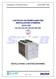
<strong>ELFO</strong>Energy makes the use of storage tanks<br />
obsolete<br />
Thanks to the new electronic controller, <strong>ELFO</strong>Energy eliminates the need for<br />
the storage tank. This consequently avoids one of the main sources of thermal<br />
dispersion and energy inefficiency in the system.
NEW ELECTRONIC CONTROLLER<br />
HYDRONIC<br />
17 - 91<br />
The new <strong>ELFO</strong>Energy units feature a latest generation electronic controller with microprocessor. It receives information (temperature, humidity etc.) on the thermal load of<br />
the environment in which comfort is to be guaranteed; based on this load, it controls and optimises the operation of the unit. In this way, there is a DYNAMIC SET POINT<br />
controlled by the microprocessor. In addition, the controller ensures a MAINTENANCE SET POINT for periods in which the outside load is reduced. These functions also<br />
allow a reduction in the number of unit start-ups and increase efficiency.<br />
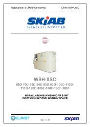
LOW RUNNING COSTS<br />
<strong>ELFO</strong>Energy can therefore ensure much higher efficiency than a traditional<br />
chiller, and much less stress on the various components (especially the<br />
compressor). Comparing, in the same system, the electrical consumption of<br />
<strong>ELFO</strong>Energy with that of a traditional chiller of the same capacity power<br />
and fitted with storage tank, the seasonal savings are around 11%.<br />
This data, together with its intrinsic reliability, make the <strong>ELFO</strong>Energy a<br />
required option both in terms of pay back and peace of mind.<br />
Seasonal consumption compariron between traditional units (with<br />
storage) and <strong>ELFO</strong>Energy units<br />
The new electronic controller therefore ensures significant energy savings, complying<br />
with the Clivet philosophy of safeguarding the environment.<br />
In the case of installation in an <strong>ELFO</strong>System, <strong>ELFO</strong>Energy can communicate with the<br />
other units installed in the system. All the components in the <strong>ELFO</strong>System communicate<br />
with one another, thanks to the <strong>ELFO</strong>Control.<br />
In this way, each device can control its own operating parameters not only based on the<br />
conditions it must respond to directly, but also those of the entire system and consequently<br />
of the entire environment. This means that maximum individual comfort is guaranteed<br />
in all conditions.<br />
BT04I090GB-01<br />
3
BT04I090GB-01<br />
4<br />
HYDRONIC<br />
17 - 91<br />
STANDARD UNIT SPECIFICATIONS<br />
COMPRESSOR<br />
hermetic orbiting scroll compressor complete with motor over-temperature and<br />
over-current devices and protection against excessive gas discharge temperature.<br />
Fitted on rubber antivibration mounts and complete with oil charge<br />
On sizes 17-21-25: rotary hermetic compressor, complete with cut -out devices,<br />
rubber anti-vibration mounts and oil charge.<br />
STRUCTURE<br />
structure made from "aluzink" plate, providing excellent mechanical characteristics<br />
and extensive corrosion strength<br />
PANELLING<br />
pre-painted plate easy panelling external that can be removed for complete<br />
access to the internal components. Lined with class 1 heat insulation and<br />
soundproofing material.<br />
INTERNAL EXCHANGER<br />
direct expansion heat exchanger, braze-welded AISI 316 stainless steel plates<br />
with large exchange surface and complete with external heat and anticondensate<br />
insulation.<br />
the exchanger comes complete with:<br />
- differential pressure switch, water side<br />
- antifreeze heater to protect the water side exchanger, preventing the formation<br />
of frost if the water temperature falls below a set value.<br />
EXTERNAL EXCHANGER<br />
heat exchange coil with aluminium fins and copper tubes in staggered rows.<br />
The coils are complete with integral subcooling circuit which assures the correct<br />
refrigerant feeding of the expansion valve. Available in different options as<br />
per optional list.<br />
FAN<br />
dual intake centrifugal fan directly coupled to an electric motor<br />
REFRIGERANT CIRCUIT<br />
The circuit is complete with:<br />
- expansion device<br />
- high pressure switch<br />
- dehydrator filter<br />
- low pressure switch<br />
ELECTRICAL PANEL<br />
the Power Section includes:<br />
- main isolator switch (size 61÷91)<br />
- compressor and fan fuses<br />
- compressor control contactor<br />
- pump control contactor<br />
- compressor thermal overload relay (size 61÷91)<br />
the control section includes:<br />
- compressor overload protection and timer<br />
- microprocessor control<br />
- relay for remote cumulative fault signal<br />
- green unit in operation signal LED<br />
- red led water flow signal<br />
CONFIGURATION CODE<br />
(1) VERSION<br />
Standard (S)<br />
- antifreeze protection<br />
- remote ON/OFF control<br />
- Electronic for Elfo Control system (optional)<br />
- proportional + integral water temperature control<br />
HYDRAULIC CIRCUIT<br />
- Centrifugal pump<br />
- water side safety valve<br />
- diaphragm expansion vessel<br />
- Water fill assembly with pressure gauge<br />
- drain valve<br />
- air bleed valve<br />
ACCESSORIES<br />
- copper / aluminium condenser coils with acrylic lining<br />
- copper / aluminium condenser coils with Fin Guard (Silver) treatment<br />
- copper / copper condenser coils<br />
- steel mesh strainer<br />
- vertical air outlet<br />
- unit without hydronic assembly<br />
- Supply voltage 230/1/50 only sizes from 31 to 41<br />
- Supply voltage 400/3/50+N only sizes from 17 to 25<br />
- serial communication module to supervisor (MODBUS)<br />
- Device for operation with low outside temperatures with variable fan speed by<br />
Inverter only sizes from 71 to 91<br />
- set point compensation with outside temperature probe<br />
- set point compensation according to the outside enthalpy<br />
- set point compensation with 4-20 mA signal<br />
- Device for low temperature operation of external air with fan variable speed<br />
only sizes from 17 to 61<br />
- control keypad for remote installation that repeats all the functions already<br />
present on the onboard microprocessor control.<br />
- local control portable keypad for unit operating control and configuration<br />
- phase monitor<br />
- rubber antivibration mounts<br />
( 1 ) ( 2 ) ( 3 )<br />
WSA-EE S 17 CE T<br />
(2) LOW TEMPERATURE<br />
Low water temperature (B)<br />
this version permits units operation with glycol solution temperature from +5°C<br />
to -8°C.<br />
available version<br />
- Brine chiller<br />
- Double set-point function<br />
S (Standard) CE (Standard) T (Standard)<br />
B<br />
(3) HEAT EXCHANGERS APPROVALS<br />
CE = PED (European testing)<br />
(4) <strong>ENERGY</strong> EFFICIENCY<br />
Standard (S)
GENERAL TECHNICAL SPECIFICATIONS<br />
Voltage: 230/1/50<br />
ELECTRICAL DATA<br />
HYDRONIC<br />
17 - 91<br />
Size 17 21 25 31 41 51 61 71 81 91<br />
COOLING<br />
Cooling capacity 1 kW 4.47 5.35 7.13 8.49 10.7 12.8 14.9 17 18.8 22.7<br />
Compressor power input 1 kW 1.46 1.88 2.31 2.79 3.3 3.98 4.86 5.26 6.21 7.48<br />
Total power input 2 kW 1.81 2.24 2.82 3.33 4.35 5.07 5.97 6.01 6.99 8.36<br />
EER Nr 2.46 2.38 2.53 2.55 2.47 2.53 2.5 2.83 2.69 2.71<br />
COMPRESSOR<br />
Type of compressors Rotativo Rotativo Rotativo Scroll Scroll Scroll Scroll Scroll Scroll Scroll<br />
No. of Compressors Nr 1 1 1 1 1 1 1 1 1 1<br />
Std Capacity control steps Nr 1 1 1 1 1 1 1 1 1 1<br />
Refrigerant charge (C1) 3 kg 2 2 3 3 3.8 4.2 5.2 5.2 6 6<br />
Refrigerant circuits Nr 1 1 1 1 1 1 1 1 1 1<br />
INTERNAL EXCHANGER<br />
Type of internal exchanger 4 PHE PHE PHE PHE PHE PHE PHE PHE PHE PHE<br />
No. of internal exchangers Nr 1 1 1 1 1 1 1 1 1 1<br />
Water flow-rate l/s 0.2 0.3 0.3 0.4 0.5 0.6 0.7 0.8 0.9 1.1<br />
Useful pump discharge head kPa 52 42 44 32 149 129 123 105 114 87<br />
Water content l 1.1 1.1 1.3 1.3 1.6 1.6 1.8 3 3 3<br />
EXTERNAL EXCHANGER<br />
Front surface m2 0.4 0.4 0.4 0.4 0.7 0.7 0.7 1.2 1.2 1.2<br />
EXTERNAL SECTION FANS<br />
Type of fans 5 CFG CFG CFG CFG CFG CFG CFG CFG CFG CFG<br />
Number of fans Nr 1 1 1 1 1 1 1 1 1 1<br />
Standard air flow l/s 694 694 1069 1042 1556 1542 1542 2861 2861 2806<br />
Installed unit power kW 0.4 0.4 0.8 0.8 1.7 1.7 1.7 2.4 2.4 2.4<br />
Max outside static pressure Pa 60 60 60 60 100 100 100 100 100 100<br />
HYDRAULIC CIRCUIT<br />
Max water side pressure kPa 800 800 800 800 800 800 800 800 800 800<br />
Safety valve calibration kPa 600 600 600 600 600 600 600 600 600 600<br />
EXPANSION VESSEL<br />
Expansion vessel capacity l 2 2 2 2 2 5 5 5 5 5<br />
No. of expansion vessels Nr 1 1 1 1 1 1 1 1 1 1<br />
POWER SUPPLY<br />
Standard power supply<br />
NOISE LEVELS<br />
V 230/1/50 230/1/50 230/1/50 400/3/50+N 400/3/50+N 400/3/50+N 400/3/50+N 400/3/50+N 400/3/50+N 400/3/50+N<br />
Sound pressure level (1 m) dB(A) 56 57 59 60 64 65 65 67 68 69<br />
DIMENSIONS<br />
Length mm 838 838 982 982 1206 1206 1206 1516 1516 1516<br />
Depth mm 561 561 647 647 724 724 724 760 760 760<br />
Height mm 649 649 648 648 721 721 721 1045 1045 1045<br />
STANDARD UNIT WEIGHTS<br />
Shipping weight kg 84 90 122 132 170 178 182 259 323 332<br />
Operating weight kg 83 89 121 130 168 176 180 256 320 329<br />
(1) data referred to the following conditions :<br />
internal exchanger water = 12/7°C<br />
room temperature = 35°C<br />
(2) The total input is given by the compressor input + fans power input + pump power input -<br />
proportional part of the water pump to supply the available head to installation input + the<br />
auxiliary circuit input<br />
(3) approximate values<br />
(4) PHE = plates<br />
Size 17 21 25 31 41<br />
F.L.A. - FULL LOAD CURRENT AT MAX ADMISSIBLE CONDITIONS<br />
F.L.A. - Pump A 1.04 1.04 1.04 1.04 3.2<br />
F.L.A. - Total A 14.1 16.7 19.8 24 30.7<br />
F.L.I. FULL LOAD POWER INPUT AT MAX ADMISSIBLE CONDITION<br />
F.L.I. - Pump kW 0.25 0.25 0.25 0.25 0.66<br />
F.L.I. - Total kW 2.654 3.285 3.865 4.75 5.636<br />
M.I.C. MAXIMUM INRUSH CURRENT<br />
M.I.C. - Value A 40.6 55.6 65.5 105.5 120.7<br />
power supply 230/1/50 Hz +/-6%<br />
for non standard voltage please contact Clivet technical office<br />
The pump is included in the total values calculation<br />
(5) CFG = centrifugal fan<br />
BT04I090GB-01<br />
5
BT04I090GB-01<br />
6<br />
HYDRONIC<br />
17 - 91<br />
Voltage: 400/3/50+N<br />
ELECTRICAL DATA<br />
Size 17 21 25 31 41 51 61 71 81 91<br />
F.L.A. - FULL LOAD CURRENT AT MAX ADMISSIBLE CONDITIONS<br />
F.L.A. - Pump A 1.04 1.04 1.04 1.04 3.2 3.2 3.2 3.2 3.2 3.2<br />
F.L.A. - Total A 7.34 8.34 11.24 12.04 15.3 20.7 22.2 23.81 24.91 27.61<br />
F.L.I. FULL LOAD POWER INPUT AT MAX ADMISSIBLE CONDITION<br />
F.L.I. - Pump kW 0.25 0.25 0.25 0.25 0.66 0.66 0.66 0.66 0.66 0.66<br />
F.L.I. - Total kW 2.64 3.26 4.04 4.58 6.03 7.05 7.99 9.76 10.91 12.94<br />
M.I.C. MAXIMUM INRUSH CURRENT<br />
M.I.C. - Value A 27.6 35.6 45.5 51.5 57.7 76.9 84.9 111.2 109.2 133.2<br />
Maximum Phase Unbalance: 2%<br />
power supply 400/3/50 (+ NEUTRAL) +/- 6%<br />
for non standard voltage please contact Clivet technical office<br />
The pump is included in the total values calculation<br />
PUMP PERFORMANCE<br />
DP (kPa)<br />
180<br />
170<br />
160<br />
150<br />
140<br />
130<br />
120<br />
110<br />
100<br />
90<br />
80<br />
70<br />
60<br />
50<br />
40<br />
30<br />
20<br />
10<br />
CURVE OF DISCHARGE HEAD WITH HYDRONIC ASSEMBLY<br />
17-21 25-31 41-51 61-71 81-91<br />
0.1 0.2 0.3 0.4 0.5 0.6 0.7 0.8 0.9 1.0 1.1 1.2 1.3 1.4 1.5 1.6<br />
Q (l/s)<br />
THE HEADS ARE INTENDED AS AVAILABLE AT<br />
THE UNIT CONNECTIONS<br />
DP = AVAILABLE HEAD<br />
Q = WATER FLOW
OPERATING LIMITS (COOLING)<br />
SOUND LEVELS<br />
Size<br />
Sound Power Level (dB) Sound<br />
pressure<br />
level<br />
Octave band (Hz)<br />
Sound<br />
power level<br />
63 125 250 500 1000 2000 4000 8000 dB(A) dB(A)<br />
17 79 71 65 67 65 61 57 48 56 70<br />
21 80 72 66 68 67 63 59 50 57 71<br />
25 83 78 72 70 68 65 59 52 59 73<br />
31 83 79 73 70 69 65 60 52 60 74<br />
41 80 80 79 75 73 70 66 59 64 78<br />
51 81 81 80 76 74 71 67 60 65 79<br />
61 83 83 80 75 74 71 67 59 65 79<br />
71 83 82 80 81 78 73 69 62 67 83<br />
81 84 83 82 83 79 74 70 63 68 84<br />
91 85 84 82 83 79 75 70 63 69 84<br />
HYDRONIC<br />
17 - 91<br />
Size 17 21 25 31 41 51 61 71 81 91<br />
EXTERNAL EXCHANGER<br />
Max air intake temperature 1 °C 49.5 48.5 47.5 47.5 47.5 48.5 46.5 48.5 47 47.5<br />
Min. air intake temperature °C 15 12 11.5 12.5 12 13 10.5 13 12 12.5<br />
Min. air intake temperature 2 °C -10 -10 -10 -10 -10 -10 -10 -10 -10 -10<br />
INTERNAL EXCHANGER<br />
Max water inlet temperature 3 °C 19 20 19 23 23 21 21 21 22.5 23.5<br />
Max water inlet temperature 4 °C 18 19 18 22 22 20 19.5 20 22 23<br />
Min. water outlet temperature 5 °C 4 4 4 4 4 4 4 4 4 4<br />
Water thermal head (min / max) are indicated in the section INTERNAL EXCHANGER<br />
PRESSURE DROP<br />
(1) unit at full load: internal exchanger water 12/7°C<br />
(2) unit with low ambient temperature device (OPTIONAL)<br />
(3) external exchanger air intake 30°C<br />
(4) external exchanger air inlet temperature 40°C<br />
(5) antifreeze intervention<br />
Measures according to ISO 3744 regulations, with respect to the EUROVENT 8/1<br />
certification.<br />
The sound power levels are referred to units working at full load, with 60 Pa of external<br />
static pressure and with 1 meter of duct on the air discharge side.<br />
BT04I090GB-01<br />
7
BT04I090GB-01<br />
8<br />
DP (kPa)<br />
HYDRONIC<br />
17 - 91<br />
CORRECTION FACTOR FOR ANTIFREEZE SOLUTIONS<br />
% ethylene glycol by weight<br />
5% 10% 15% 20% 25% 30% 35% 40%<br />
Freezing temperature °C -2.0 -3.9 -6.5 -8.9 -11.8 -15.6 -19.0 -23.4<br />
Safety temperature °C 3.0 1.0 -1.0 -4.0 -6.0 -10.0 -14.0 -19.0<br />
Cooling Capacity Factor Nr 0.995 0.990 0.985 0.981 0.977 0.974 0.971 0.968<br />
Compressor input Factor Nr 0.997 0.993 0.990 0.988 0.986 0.984 0.982 0.981<br />
Internal exchanger Glycol solution flow Factor Nr 1.003 1.010 1.020 1.033 1.050 1.072 1.095 1.124<br />
Pressure drop Factor Nr 1.029 1.060 1.090 1.118 1.149 1.182 1.211 1.243<br />
The correction factors shown refer to water and glycol ethylene mixes used to prevent the formation of frost on the exchangers in the water circuit during inactivity in winter.<br />
FOULING CORRECTION FACTOR<br />
INTERNAL EXCHANGER PRESSURE DROP<br />
80<br />
75<br />
70<br />
65<br />
60<br />
55<br />
50<br />
45<br />
40<br />
35<br />
30<br />
25<br />
20<br />
15<br />
10<br />
INTERNAL EXCHANGER<br />
m² °C/W F1 FK1<br />
0.44 x 10^(-4) 1.00 1.00<br />
0.88 x 10^(-4) 0.97 0.99<br />
1.76 x 10^(-4) 0.94 0.98<br />
The cooling performance values provided in the tables are based on the external exchanger having clean plates (fouling factor 1). For different fouling factor values, multiply the performance<br />
by the coefficients shown in the table.<br />
F1 = Cooling capacity correction factors<br />
FK1 = Compressor power input correction factor<br />
17-21<br />
25-31<br />
0.1 0.2 0.3 0.4 0.5 0.6 0.7 0.8 0.9 1.0 1.1 1.2 1.3 1.4 1.5 1.6 1.7<br />
41-51<br />
Q (l/s)<br />
61-71<br />
81-91<br />
EXCHANGER PRESSURE DROP LIMIT. WARNING:<br />
DON'T USE OVER THIS LIMIT<br />
UNIT WITHOUT HYDRONIC ASSEMBLY<br />
DP = PRESSURE DROP<br />
Q = WATER FLOW<br />
EXCHAMGER PRESSURE DROP LIMIT. WARNING:<br />
DON'T USE BELOW THIS LIMIT.
COOLING PERFORMANCE<br />
Size<br />
17<br />
21<br />
25<br />
31<br />
41<br />
51<br />
61<br />
To<br />
(ºC)<br />
6<br />
7<br />
8<br />
9<br />
10<br />
11<br />
6<br />
7<br />
8<br />
9<br />
10<br />
11<br />
6<br />
7<br />
8<br />
9<br />
10<br />
11<br />
6<br />
7<br />
8<br />
9<br />
10<br />
11<br />
6<br />
7<br />
8<br />
9<br />
10<br />
11<br />
6<br />
7<br />
8<br />
9<br />
10<br />
11<br />
6<br />
7<br />
8<br />
9<br />
10<br />
11<br />
kWf = Cooling capacity in kW<br />
kWe = Compressor power input in kW<br />
To = Internal exchanger water outlet temperature in° C<br />
Performances in function of the inlet/outlet water temperature differential = 5°C<br />
EXTERNAL EXCHANGER AIR INTAKE TEMPERATURE (ºC)<br />
25 30 35 40 45 47<br />
HYDRONIC<br />
17 - 91<br />
kWf kWe kWf kWe kWf kWe kWf kWe kWf kWe kWf kWe kWf kWe<br />
4.75 1.20 4.53 1.31 4.33 1.45 4.15 1.60<br />
4.90 1.20 4.68 1.32 4.47 1.46 4.27 1.62 4.08 1.80 4.01 1.88<br />
5.05 1.21 4.82 1.32 4.61 1.46 4.40 1.63 4.19 1.81 4.11 1.89<br />
5.20 1.21 4.97 1.33 4.74 1.47 4.52 1.64 4.30 1.82 4.22 1.90<br />
5.35 1.21 5.12 1.34 4.88 1.48 4.65 1.65 4.41 1.84 4.32 1.92<br />
5.51 1.21 5.27 1.34 5.02 1.49 4.77 1.66 4.52 1.85 4.41 1.93<br />
5.94 1.51 5.57 1.67 5.20 1.86 4.83 2.07 4.44 2.31 4.29 2.42<br />
6.14 1.52 5.76 1.69 5.37 1.88 4.98 2.09 4.59 2.34 4.43 2.44<br />
6.34 1.54 5.94 1.71 5.54 1.90 5.14 2.12 4.74 2.36 4.58 2.47<br />
6.53 1.56 6.12 1.72 5.72 1.92 5.30 2.14 4.89 2.39 4.72 2.49<br />
6.72 1.57 6.30 1.74 5.89 1.94 5.47 2.16 5.04 2.41 4.87 2.52<br />
6.89 1.59 6.48 1.77 6.06 1.96 5.63 2.19 5.20 2.44 5.02 2.54<br />
7.66 1.92 7.29 2.10 6.93 2.29 6.58 2.49 6.24 2.70 6.11 2.79<br />
7.88 1.93 7.50 2.11 7.14 2.31 6.77 2.51 6.42 2.72 6.28 2.81<br />
8.10 1.94 7.71 2.12 7.34 2.32 6.97 2.53 6.60 2.74 6.46 2.83<br />
8.31 1.95 7.92 2.13 7.54 2.33 7.16 2.54 6.78 2.76 6.63 2.84<br />
8.53 1.95 8.13 2.14 7.73 2.34 7.34 2.55 6.96 2.77 6.81 2.86<br />
8.74 1.96 8.33 2.15 7.92 2.35 7.52 2.56 7.13 2.79 6.98 2.88<br />
9.12 2.18 8.69 2.46 8.23 2.77 7.74 3.10 7.20 3.45 6.98 3.60<br />
9.42 2.21 8.98 2.49 8.50 2.79 7.99 3.12 7.44 3.48 7.21 3.63<br />
9.72 2.23 9.27 2.51 8.77 2.82 8.25 3.15 7.68 3.51 7.44 3.67<br />
10.0 2.25 9.55 2.54 9.05 2.85 8.50 3.19 7.92 3.55 7.68 3.71<br />
10.3 2.27 9.84 2.56 9.32 2.88 8.76 3.22 8.16 3.59 7.91 3.75<br />
10.6 2.29 10.1 2.59 9.60 2.91 9.03 3.26 8.41 3.64 8.15 3.79<br />
11.5 2.67 10.9 2.97 10.4 3.29 9.76 3.63 9.10 3.98 8.82 4.13<br />
11.8 2.68 11.3 2.98 10.7 3.30 10.1 3.63 9.39 3.97 9.11 4.11<br />
12.2 2.68 11.6 2.99 11.0 3.30 10.4 3.63 9.69 3.96 9.40 4.10<br />
12.6 2.69 12.0 2.99 11.4 3.30 10.7 3.62 9.98 3.95 9.68 4.08<br />
12.9 2.69 12.3 3.00 11.7 3.30 11.0 3.62 10.3 3.94 9.97 4.07<br />
13.3 2.70 12.7 3.00 12.0 3.30 11.3 3.62 10.6 3.93 10.2 4.06<br />
13.8 3.21 13.2 3.57 12.5 3.96 11.7 4.40 10.9 4.87 10.6 5.07<br />
14.2 3.23 13.6 3.59 12.9 3.98 12.1 4.42 11.3 4.89 10.9 5.09<br />
14.7 3.25 14.0 3.61 13.2 4.00 12.5 4.44 11.6 4.91 11.3 5.12<br />
15.2 3.28 14.4 3.63 13.7 4.02 12.8 4.46 12.0 4.94 11.7 5.14<br />
15.6 3.30 14.9 3.65 14.1 4.04 13.3 4.48 12.4 4.96 12.0 5.16<br />
16.1 3.32 15.3 3.67 14.5 4.06 13.7 4.50 12.8 4.98 12.4 5.18<br />
16.2 3.90 15.4 4.34 14.5 4.83 13.6 5.36 12.8 5.94<br />
16.6 3.93 15.8 4.37 14.9 4.87 14.0 5.40 13.1 5.99<br />
17.1 3.96 16.2 4.41 15.4 4.91 14.4 5.45 13.5 6.03<br />
17.6 3.99 16.7 4.45 15.8 4.95 14.9 5.49 13.9 6.08<br />
18.1 4.04 17.2 4.49 16.3 5.00 15.3 5.54 14.3 6.14<br />
18.6 4.08 17.7 4.54 16.7 5.05 15.7 5.60 14.7 6.19<br />
50<br />
BT04I090GB-01<br />
9
BT04I090GB-01<br />
10<br />
HYDRONIC<br />
17 - 91<br />
COOLING PERFORMANCE<br />
Size<br />
71<br />
81<br />
91<br />
To<br />
(ºC)<br />
6<br />
7<br />
8<br />
9<br />
10<br />
11<br />
6<br />
7<br />
8<br />
9<br />
10<br />
11<br />
6<br />
7<br />
8<br />
9<br />
10<br />
11<br />
kWf = Cooling capacity in kW<br />
kWe = Compressor power input in kW<br />
To = Internal exchanger water outlet temperature in° C<br />
Performances in function of the inlet/outlet water temperature differential = 5°C<br />
EXTERNAL EXCHANGER AIR INTAKE TEMPERATURE (ºC)<br />
25 30 35 40 45 47<br />
kWf kWe kWf kWe kWf kWe kWf kWe kWf kWe kWf kWe kWf kWe<br />
18.3 4.17 17.4 4.67 16.5 5.21 15.5 5.81 14.5 6.46 14.1 6.73<br />
18.9 4.21 18.0 4.71 17.0 5.26 16.0 5.85 14.9 6.49 14.5 6.76<br />
19.5 4.25 18.6 4.75 17.6 5.30 16.5 5.89 15.4 6.53 14.9 6.80<br />
20.1 4.30 19.2 4.80 18.1 5.34 17.1 5.94 15.9 6.57 15.4 6.84<br />
20.8 4.34 19.8 4.85 18.7 5.39 17.6 5.98 16.4 6.62 15.9 6.88<br />
21.4 4.39 20.4 4.90 19.3 5.44 18.2 6.03 17.0 6.67 16.5 6.93<br />
20.3 4.99 19.3 5.54 18.3 6.16 17.2 6.84 16.2 7.59 15.8 7.91<br />
20.9 5.03 19.9 5.59 18.8 6.21 17.8 6.90 16.8 7.66 16.3 7.98<br />
21.6 5.07 20.5 5.63 19.4 6.26 18.4 6.96 17.3 7.73 16.9 8.06<br />
22.2 5.11 21.1 5.68 20.0 6.32 18.9 7.03 17.9 7.81 17.5 8.14<br />
22.9 5.16 21.7 5.73 20.6 6.38 19.5 7.10 18.5 7.89 18.0 8.23<br />
23.5 5.21 22.3 5.78 21.2 6.44 20.1 7.17 19.0 7.97 18.6 8.32<br />
24.4 6.01 23.2 6.68 21.9 7.42 20.7 8.22 19.5 9.09 19.0 9.45<br />
25.1 6.05 23.9 6.72 22.6 7.46 21.4 8.26 20.1 9.13 19.6 9.50<br />
25.9 6.09 24.7 6.76 23.4 7.50 22.1 8.30 20.7 9.18 20.2 9.54<br />
26.7 6.12 25.4 6.80 24.1 7.54 22.7 8.34 21.4 9.22 20.8 9.59<br />
27.5 6.16 26.2 6.83 24.8 7.57 23.4 8.38 22.0 9.26 21.4 9.63<br />
28.4 6.19 27.0 6.87 25.6 7.61 24.1 8.42 22.7 9.30 22.1 9.66<br />
50
14<br />
8<br />
2<br />
10 1<br />
31 262 247 21<br />
13<br />
(1) COMPRESSOR<br />
(2) ELECTRICAL PANEL<br />
(3) WATER OUTLET 1" GAS<br />
(4) WATER FILL ASSEMBLY WITH PRESSURE GAUGE<br />
(5) WATER INLET 1" GAS<br />
(6) HORIZONTAL SIDE AIR DISCHARGE<br />
(7) EXPANSION VESSEL<br />
(8) EXTERNAL EXCHANGER<br />
(9) INTERNAL EXCHANGER<br />
(10) PUMP<br />
(11) POWER INPUT<br />
(12) CLEARANCE ACCESS RECOMMENDED<br />
(13) OUTLET CENTRIFUGAL FAN<br />
(14) UPFLOW VERSIONS<br />
(G) POSITION OF THE UNIT'S CENTRE OF GRAVITY<br />
7<br />
4<br />
DIMENSIONALES/WEIGHT DISTRIBUTION<br />
649<br />
308<br />
12<br />
72<br />
500<br />
12<br />
11<br />
249<br />
280<br />
430<br />
838<br />
104<br />
18 866<br />
18<br />
W3<br />
W1<br />
170<br />
150<br />
M<br />
9<br />
620<br />
"G"<br />
13<br />
304<br />
Size 17 21<br />
M mm 340 328<br />
N mm 526 538<br />
O mm 127 122<br />
P mm 164 169<br />
Length mm 838 838<br />
Depth mm 561 561<br />
Height mm 649 649<br />
W1 kg 29 33<br />
W2 kg 19 20<br />
W3 kg 22 23<br />
W4 kg 14 14<br />
Operating weight kg 83 89<br />
Shipping weight kg 84 90<br />
5<br />
3<br />
N<br />
48<br />
47 268 334<br />
W4<br />
P O<br />
W2<br />
159<br />
291<br />
110<br />
6<br />
576<br />
45<br />
8<br />
HYDRONIC<br />
17 - 91<br />
11<br />
7<br />
BT04I090GB-01<br />
11
BT04I090GB-01<br />
12<br />
2<br />
HYDRONIC<br />
17 - 91<br />
29 289 307 22<br />
8 7 9<br />
1<br />
4<br />
13<br />
DIMENSIONALES/WEIGHT DISTRIBUTION<br />
648<br />
(1) COMPRESSOR<br />
(2) ELECTRICAL PANEL<br />
(3) WATER OUTLET 1" GAS<br />
(4) WATER FILL ASSEMBLY WITH PRESSURE GAUGE<br />
(5) WATER INLET 1" GAS<br />
(6) HORIZONTAL SIDE AIR DISCHARGE<br />
(7) EXPANSION VESSEL<br />
(8) EXTERNAL EXCHANGER<br />
(9) INTERNAL EXCHANGER<br />
(10) PUMP<br />
(11) POWER INPUT<br />
(12) CLEARANCE ACCESS RECOMMENDED<br />
(13) OUTLET CENTRIFUGAL FAN<br />
(14) UPFLOW VERSIONS<br />
(G) POSITION OF THE UNIT'S CENTRE OF GRAVITY<br />
14<br />
330<br />
73<br />
500 155<br />
12<br />
200<br />
W3<br />
W1<br />
11<br />
287<br />
12<br />
M<br />
496<br />
9<br />
10<br />
"G"<br />
982<br />
5 3<br />
337<br />
1015<br />
783<br />
8<br />
13<br />
6<br />
13<br />
148<br />
Size 25 31<br />
45<br />
M mm 396 378<br />
N mm 619 637<br />
O mm 123 113<br />
P mm 217 227<br />
Length mm 982 982<br />
Depth mm 647 647<br />
Height mm 648 648<br />
W1 kg 48 55<br />
W2 kg 30 33<br />
W3 kg 27 27<br />
W4 kg 17 16<br />
Operating weight kg 121 130<br />
Shipping weight kg 122 132<br />
N<br />
299 302<br />
47<br />
W4<br />
O<br />
P<br />
W2<br />
340<br />
28 575<br />
26<br />
19<br />
11
721<br />
2<br />
29 342 330 25<br />
7<br />
13<br />
8<br />
10<br />
724<br />
4<br />
14<br />
500<br />
12<br />
200<br />
306<br />
103<br />
DIMENSIONALES/WEIGHT DISTRIBUTION<br />
11<br />
8<br />
W3 W4<br />
W1<br />
(1) COMPRESSOR<br />
(2) ELECTRICAL PANEL<br />
(3) WATER OUTLET 1" GAS<br />
(4) WATER FILL ASSEMBLY WITH PRESSURE GAUGE<br />
(5) WATER INLET 1" GAS<br />
(6) HORIZONTAL SIDE AIR DISCHARGE<br />
(7) EXPANSION VESSEL<br />
(8) EXTERNAL EXCHANGER<br />
(9) INTERNAL EXCHANGER<br />
(10) CENTRIFUGAL PUMP<br />
(11) POWER INPUT<br />
(12) CLEARANCE ACCESS RECOMMENDED<br />
(13) OUTLET CENTRIFUGAL FAN<br />
(14) UPFLOW VERSIONS<br />
(G) POSITION OF THE UNIT'S CENTRE OF GRAVITY<br />
1<br />
374<br />
1<br />
12<br />
455<br />
10<br />
9<br />
3<br />
5<br />
"G"<br />
1206<br />
1244<br />
13<br />
603 308<br />
131 1032<br />
M<br />
13<br />
297<br />
50<br />
46<br />
W2<br />
Size 41 51 61<br />
N<br />
339<br />
O<br />
P<br />
M mm 460 448 443<br />
N mm 784 796 801<br />
O mm 197 196 193<br />
P mm 225 226 229<br />
Length mm 1206 1206 1206<br />
Depth mm 724 724 724<br />
Height mm 721 721 721<br />
W1 kg 57 61 64<br />
W2 kg 34 34 35<br />
W3 kg 50 53 54<br />
W4 kg 29 30 30<br />
Operating weight kg 168 176 180<br />
Shipping weight kg 170 178 182<br />
691<br />
11<br />
173<br />
422<br />
131<br />
24<br />
40<br />
2<br />
HYDRONIC<br />
17 - 91<br />
7<br />
13<br />
9<br />
6<br />
BT04I090GB-01<br />
13
1045<br />
13<br />
HYDRONIC<br />
17 - 91<br />
13<br />
426 299<br />
14<br />
2 1 10<br />
22<br />
CLIVET S.P.A.<br />
Feltre (BL) - ITALY<br />
Tel . +39 0439 3131<br />
Fax +39 0439 313300<br />
info @clivet.it<br />
733<br />
4 13 12<br />
(1) COMPRESSOR<br />
(2) ELECTRICAL PANEL<br />
(3) WATER OUTLET 1" GAS<br />
(4) WATER FILL ASSEMBLY WITH PRESSURE GAUGE<br />
(5) WATER INLET 1" GAS<br />
(6) HORIZONTAL SIDE AIR DISCHARGE<br />
(7) EXPANSION VESSEL<br />
(8) EXTERNAL EXCHANGER<br />
(9) INTERNAL EXCHANGER<br />
(10) CENTRIFUGAL PUMP<br />
(11) POWER INPUT<br />
(12) CLEARANCE ACCESS RECOMMENDED<br />
(13) OUTLET CENTRIFUGAL FAN<br />
(14) UPFLOW VERSIONS<br />
(G) POSITION OF THE UNIT'S CENTRE OF GRAVITY<br />
1043<br />
500<br />
DIMENSIONALES/WEIGHT DISTRIBUTION<br />
670<br />
149<br />
CLIVET ESPAÑA S.A.<br />
Madrid - SPAIN<br />
Tel. +34 916 658 280<br />
Fax +34 916 657 806<br />
info @clivet.es<br />
210<br />
W3<br />
11<br />
10<br />
9<br />
"G"<br />
3<br />
4<br />
5<br />
CLIVET UK LTD<br />
Sevenoaks (Kent) - U.K.<br />
Tel . +44 (0) 1732 464141<br />
Fax +44 ( 0) 1732 741575<br />
info @clivet - uk.co.uk<br />
CLIVET NEDE RLAND B.V.<br />
Amersfoort - Netherlands<br />
Tel . +31 (0) 33 7503420<br />
Fax + 31 (0) 33 7503424<br />
info @clivet .nl<br />
CLIVET TUNISIE S. a.r.l.<br />
Sidi Rezig - TUNISIE<br />
Tel. + 216 71 426 285<br />
Fax + 216 71 429 285<br />
clivet.tunisie @ planet.tn<br />
The data contained in this bulletin is not binding and may be changed by the manufacturer without prior notice. All reproduction, even partial, is prohibited.<br />
© Copyright - CLIVET S.p.A. - Feltre (BL) - Italy<br />
1516<br />
241<br />
W4<br />
W1 W2<br />
6<br />
200<br />
454<br />
459<br />
7<br />
M<br />
1241<br />
8<br />
13<br />
488<br />
13<br />
97 420<br />
526<br />
1253 57<br />
Size 71 81 91<br />
M mm 540 452 455<br />
N mm 700 788 785<br />
O mm 306 296 304<br />
P mm 344 354 346<br />
Length mm 1516 1516 1516<br />
Depth mm 760 760 760<br />
Height mm 1045 1045 1045<br />
W1 kg 77 112 112<br />
W2 kg 60 64 65<br />
W3 kg 69 93 98<br />
W4 kg 53 54 57<br />
Operating weight kg 256 320 329<br />
Shipping weight kg 259 323 332<br />
N<br />
O<br />
P<br />
598<br />
68 950<br />
22<br />
11<br />
7<br />
9