Operating Instructions
Operating Instructions
Operating Instructions

Create successful ePaper yourself
Turn your PDF publications into a flip-book with our unique Google optimized e-Paper software.
<strong>Operating</strong><strong>Instructions</strong>
Measurable success by Sewerin equipmentCongratulations. You have chosen a quality instrument manufacturedby Hermann Sewerin GmbH.Our equipment will provide you with the highest standards of performance,safety and efficiency. They correspond with the national and internationalguide-lines.Please read and understand the following operating instructions beforeusing the equipment; they will help you to use the instrument quickly andcompetently. If you have any queries we are available to offer adviceand assistance at any time.YoursHermann Sewerin GmbHRobert-Bosch-Straße 333334 Gütersloh, GermanyTel.: +49 5241 934-0Fax: +49 5241 934-444www.sewerin.cominfo@sewerin.comSewerin LtdHertfordshireUKPhone: +44 1462-634363www.sewerin.co.ukinfo@sewerin.co.ukSEWERIN Sarl17, rue Ampère - BP 21167727 HOERDT CEDEX, FranceTél. : +33 3 88 68 15 15Fax : +33 3 88 68 11 77www.sewerin.frsewerin@sewerin.frSewerin USA, LLC13551 W. 43rd Drive, Unit RGolden, CO 80403-7272Phone: +1 303-424-3611Fax: +1 303-420-0033www.sewerin.netjerry.palmer@sewerin.netSEWERIN IBERIA S.L.c/ Cañada Real de Merinas, 17Centro de Negocios „Eisenhower“Edificio 5; Planta 2 - C28042 Madrid, EspañaTel.: +34 91 74807-57Fax: +34 91 74807-58www.sewerin.esinfo@sewerin.es
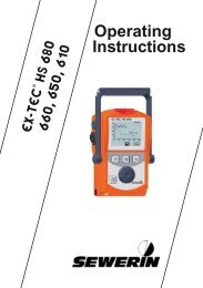
Illustration EX-TEC PM 4Overview of deviceSensor headSuspension fittingAlarm lightBuzzerLCD matrixKeypadBattery chargecontactsLiquid Crystal DisplayCase / operatingmodeAlarm thresholdactivationGas typeBattery statusGas concentrationUnit of measureTrend bar
OverviewControl keysDevice On/Off(press and hold for approx. 3 seconds)Used to enter / confirm selection(press briefly)Used to switch between applications /menu item selectionsPress and hold one key for 2 seconds:accesses user menuPress and hold both keys for 2 seconds:accesses advanced settingsSymbols on LCDDisplay of available operating hours(5 bars = 5 hours)Alarm thresholds are activatedDevice is in House applicationDevice is in Confined spaces applicationDevice is in Warning %LEL applicationDevice is in Measuring VOL% applicationDevice is in Automatic measuring rangechangeover mode
<strong>Operating</strong> <strong>Instructions</strong>EX-TEC ® PM 428.11.2008 – V2.XXX – 105806 – en
Symbols usedCAUTION! Danger of injuries!This symbol refers to important safety instructions.Adhere strictly to these instructions to avoid injuries!CAUTION! Danger of damages!This symbol refers to important safety instructions.Adhere strictly to these instructions to avoid materialdamages!Note:This symbol refers to information and useful tips whichare exceeding the basic operating procedures.Symbols for the applications:HouseConfined spaceWarning %LELMeasuring vol%
ContentsPage1 General.....................................................................................11.1 Warranty....................................................................................11.2 Purpose.....................................................................................21.3 Intended use..............................................................................21.4 General safety information.........................................................32 Features....................................................................................52.1 Visual signals and audible signals.............................................52.2 Measurement principles.............................................................62.3 Explosion protection..................................................................73 Operation..................................................................................93.1 General information on operation..............................................93.1.1 Operator guidance..................................................................93.1.2 <strong>Operating</strong> modes..................................................................103.2 Measuring mode...................................................................... 113.2.1 User menu............................................................................143.2.2 Setting the zero point............................................................153.2.3 House application.................................................................163.2.4 Confined spaces application.................................................183.2.5 Warning %LEL application....................................................203.2.6 Measuring VOL% application...............................................233.2.7 Function control....................................................................253.2.8 Changing gas types..............................................................263.3 Advanced settings...................................................................273.3.1 Access..................................................................................273.3.2 Menu structure......................................................................293.3.3 Procedure.............................................................................303.3.4 Info menu..............................................................................323.3.4.1 Adjustment menu...............................................................323.3.4.2 System menu.....................................................................333.3.4.3 Hardware menu.................................................................373.3.4.4 Memory menu....................................................................403.4 Connecting accessory devices................................................41I
ContentsPage4 Charging and battery operation...........................................424.1 General information on charging and battery operation..........424.1.1 Suitable types of rechargeable and disposable batteries.....424.1.1.1 Devices with serial numbers 060 0X and 061 0X..............424.1.1.2 Devices with serial numbers 060 1X and 061 1X..............434.1.2 Setting the rechargeable / disposable battery type...............444.2 Battery alarm...........................................................................444.3 Operation with nickel metal hydride rechargeable batteries(NiMH).....................................................................................454.4 Operation with alkaline non-rechargeable batteries................475 Maintenance...........................................................................485.1 Function control.......................................................................485.2 Testing indication accuracy with test gas.................................495.3 Adjustment...............................................................................515.3.1 ppm range.............................................................................525.3.2 LEL range and % vol. range.................................................535.3.3 Confirming adjustment..........................................................545.4 Servicing..................................................................................545.5 Pump.......................................................................................555.5.1 Function control of pump......................................................555.5.2 Changing the pump filter.......................................................565.5.3 Changing the sensor filter.....................................................566 Faults......................................................................................577 Technical data........................................................................587.1 Features...................................................................................587.2 Alarm thresholds......................................................................597.2.1 Alarm thresholds for gas type methane CH 4........................597.2.2 Setting ranges of alarm thresholds for different gas types...617.3 Response times.......................................................................627.4 Sensors....................................................................................637.5 Ranges of use..........................................................................647.6 Pump capacity.........................................................................647.7 Power supply...........................................................................647.8 Dimensions and weight............................................................647.9 Technical information...............................................................657.10 Advice on disposal...................................................................67II
ContentsPage8 Available models and accessories.......................................688.1 Available models......................................................................688.2 Accessories.............................................................................69Appendix...............................................................................................74Gas types...............................................................................................74Setting ranges for test gases.................................................................78Test certificates......................................................................................79Declaration of Conformity......................................................................80Inspection protocols...............................................................................81Entering a user name.............................................................................83List of abbreviations...............................................................................85Index......................................................................................................86III
1General1General1.1WarrantyThe following instructions must be complied with in order for anywarranty to be applicable regarding functionality and safe operationof this equipment.Hermann Sewerin GmbH cannot be held responsible for any damagesresulting from non-compliance with these instructions. Thewarranty and liability provisions of the terms of sale and deliveryof Hermann Sewerin GmbH are not affected by the informationgiven below.•zThis product must only be operated after the relevant operatinginstructions have been read and understood.•zThis product may only be operated by qualified professionalswho are familiar with the legal requirements (Germany:DVGW).•zThis product must only be used for its intended purpose.•zThis product is only suitable for use in industrial and commercialapplications.•zRepairs must only be carried out by a specialist technician orby other suitably trained personnel.•zChanges or modifications to this product must not be carriedout without approval from Hermann Sewerin GmbH. The manufacturercannot be held responsible for damages if unapprovedmodifications have been made.•zOnly accessories supplied by Hermann Sewerin GmbH maybe used with this product.•zAll repairs must be carried out using replacement parts thathave been approved by Hermann Sewerin GmbH.•zOnly approved battery types may be used, otherwise the devicewill not be explosion-proof.•zThe manufacturer reserves the right to make technical modificationsin the course of further development.Generally applicable safety and accident-prevention regulationsmust be complied with, in addition to the information provided inthis manual.1
1General1.2PurposeThe EX-TEC PM 4 is an electronic handheld device for the detectionand measurement of gas concentrations. Equipped withthree sensors, it can be used for the ppm range, the % vol. rangeand the LEL range.The EX-TEC PM 4 is available as a diffusion device (without apump) or pump device (with an integrated pump).Note:These operating instructions describe the functionsof firmware version 2.XXX. The manufacturerreserves the right to make technical changes.The information provided here refers to a fullyequipped EX-TEC PM 4, including pump (pumpdevice). It also applies for diffusion devices.1.3Intended useAccording to DVGW Note G 465-4 the device can be used forthe following purposes:• zTesting in houses/buildings ,e.g. measuring minute gas concentrations in buildings andlocating the origin of the gas• zTesting in confined spaces ,e.g. measuring the gas concentration in confined spaces orshafts with an increased potential of gas dispersal• zWarning against explosive gas concentrations ,e.g. for monitoring work areas whilst carrying out work to gaspipes or gas systems• zMeasurement of gas concentrations ,e.g. when decommissioning gas systemsWARNING!The EX-TEC PM 4 is not suitable for the location oranalysis of leaks in underground pressure lines.2
1General1.4General safety information• zThe EX-TEC PM 4 has been tested to ensure that it is explosionproofin accordance with European standards (CENELEC).• zThe functional safety of the EX-TEC PM 4 has been testedin the LEL range, Warning (%LEL) application, for gas typesmethane (CH 4 ) and propane (C 3 H 8 ).• zUse only original SEWERIN accessories with the EX-TEC PM 4.For Flex handheld probe HG4 and Flex probe HG4, useonly SEWERIN-approved filters with activated carbon.Otherwise, the functional safety of the EX-TEC PM 4 is notguaranteed.• zAlways open the battery compartment of the EX-TEC PM 4 andrecharge the batteries outside the potentially explosive area.•zAlways use the test gases in well ventilated areas.• zAlways operate the pump device model of the EX-TEC PM 4with the pump switched on.•zAlways carry out a function control (see Section 5.1) after theEX-TEC PM 4 has suffered an impact (for example, if droppedaccidentally). Readjust the zero point if necessary (see Section5.3).• zThe EX-TEC PM 4 complies with the limits of the EMC Directive.Always observe the information in the manuals of (mobile)radio equipment when using the device close to (mobile) radioequipment.• zUse the EX-TEC PM 4 with the following gases only:––Methane (CH4)––Propane (C3H 8 )––Butane (C4H 10 )––Hexane (C6H 14 )––Nonane (C9H 20 )–– Kerosene (JFUEL)––Hydrogen (H2)––Acetylene (C2H 2 )3
1GeneralWARNING!Follow the advice regarding explosion protection(see Section 2.3).zWhen the• Warning %LEL application is in use, a brief audiblesignal emitted every 5 seconds indicates that the deviceis working properly. If no operating signal sounds, there is noguarantee that the gas concentration is being monitored. Youmust leave the danger zone immediately.4
2Features2 FeaturesThe EX-TEC PM 4 is available in two models (see Section 8.1):•zDiffusion device: basic device without a pump• zPump device: basic device with an integrated pump(designation on back of device: P)The EX-TEC PM 4 is suitable for the following applications:–– House–– Confined spaces–– Warning %LEL–– Measuring vol%2.1Visual signals and audible signalsThe device features two signalling mechanisms:•zRed alarm light on top of the device•zBuzzer on the front of the deviceNote:These signalling mechanisms cannot be switchedoff.An audible signal is emitted each time a key is pressed:• zVery long signal On error message• zLong signalWhen switching device off,When changing menuszShort signal• When switching device on,When confirming a selection,When navigating within a menu5
2Features2.2 Measurement principlesThe device features three sensors:Semiconductor sensorMeasuring rangeApplicationCatalytic combustion sensorMeasuring rangeApplicationThermal conductivity sensorMeasuring rangeApplication0 to 10,000 ppmHouseConfined spaces0 to 100 % LELWarning %LEL0 to 100 % vol.Measuring vol%HouseConfined spaces6
2Features2.3 Explosion protectionThe EX-TEC PM 4 features the following explosion-protectionclassifications:II 2 G Ex de ib IIB T4Basic device without leather bag for:––Methane CH4––Propane C3H 8––Butane C4H 10––Hexane C6H 14––Nonane C9H 20–– Kerosene (JFUEL)II 2 G Ex de ib IIC T4Basic device with leather bag for:–– Hydrogen––Acetylene (C2H 2 )––Methane CH4––Propane C3H 8––Butane C4H 10––Hexane C6H 14––Nonane C9H 20–– Kerosene (JFUEL)The respective test certificates are provided in the appendix.7
2FeaturesWARNING!It is essential to observe the following points to ensurethat the device is explosion-proof:–– Always open the battery compartment outside thepotentially explosive area.–– Always recharge the batteries outside the potentiallyexplosive area.–– Use only approved battery types.–– Use of the leather bag is mandatory to achieveclass IIC for gas types hydrogen (H 2 ) und acetylene(C 2 H 2 ).8
3Operation3 Operation3.1General information on operation3.1.1 Operator guidanceThere are two ways to operate the EX-TEC PM 4:–– Operator guidance by application–– Operator guidance by sensorThese operating instructions are based on operator guidance byapplication in accordance with DVGW Note G 465-4:––Testing in houses/buildings ( House application)––Testing in confined spaces ( Confined spaces application)–– Warning against explosive gas concentrations(Warning %LEL application)–– Measurement of gas concentrations(Measuring VOL% application)Note:The factory default operator guidance setting forthe device is Application. This can be changedto Sensor in the advanced settings (see Section3.3.4.2).9
3Operation3.1.2 <strong>Operating</strong> modesThe device is operated in two modes:•zMeasuring mode (Section 3.2)Measurements are taken in measuring mode. The zero pointcan be set, the application can be changed and the gas typecan be selected via the user menu.•zAdvanced settings (Section 3.3)The advanced settings allow you to change specifications forthe measurements as well as other device settings (e.g. adjustment,system, hardware, etc.). You cannot perform measurementsin the advanced settings.10
3Operation3.2 Measuring modeThe device is switched off.Note:Always switch the device on in fresh air.• zPress the key for approximately 3 seconds.The device switches on. At this point, the two signalling mechanismsare always tested.WARNING!Do not use the device if you do not see the visualsignal and hear the audible signal briefly whenswitching on the device.The LCD switches on. The pump runs with constant outputpower.The two start screens shown below are displayed:Start screenDisplay:–– Device type (EX TEC PM4)–– Firmware version (V2.000)––Integrated sensors(PPM LEL VOL)Date/timeDisplay:–– Date (27/11/2008)–– Time (12:37)–– User data11
3OperationThe device accesses the preset application. Two additionalscreens are displayed automatically.Note:The start-up application can be changed in the advancedsettings (see Section 3.3.4.3). The factorydefault setting for the device is the Warning %LELapplication.Display screens for the different applications:•zHouseMeasuring rangeName of application with specificationof associated signals andmeasurement unitMeasurement dataMeasurement data display•zConfined spacesMeasuring rangeName of application with specificationof associated signals andmeasurement unitMeasurement dataMeasurement data display12
3Operation•zWarning %LELMeasuring rangeName of application with specificationof measurement unitMeasurement dataMeasurement data display•zMeasuring VOL%Measuring rangeName of application with specificationof measurement unitMeasurement dataMeasurement data displayYou cannot input any information until the device has stoppedcycling through the displays. The device is not in measuring modeuntil the Measurement data screen is displayed.Note:When the device is switched on, the sensors mustwarm up. The duration of the warm-up time dependson the sensor type.After switching on the device, changing the measuringrange or setting the zero point, you may noticethe reading flashing on the display. The device isonly ready for use when the displayed reading stopsflashing.13
3Operation3.2.1 User menuMeasuring mode comprises the following functional scope:–– Zero point correction–– Application selection–– Confirmation of function control–– Gas type (optional)g modeThe zero functions point in the user menu are described in Sections 3.2.2to 3.2.8. houseconfined spaceWarning %LELTo Measuring select functions, vol% you must first access the user menu:inspection ok• zPress type of the gas key or the key for approximately 2 seconds.The user menu is displayed:zero pointhouseconfined spaceWarning %LELMeasuring vol%inspection oktype of gasTo move between menu items:•zNavigate up and down in the menu by briefly pressing theorkey.• zConfirm your selection by briefly pressing the key.If the selection is not confirmed, the display reverts back to measuringmode after approximately 10 seconds.14
3Operation3.2.2 Setting the zero pointIn general, the device sets the zero point automatically. However,in certain cases, values other than zero may be displayed whenthe device is switched on. This indicates a deviating zero point,meaning that the device must be adjusted manually to environmentalconditions.Note:The zero point must be set separately for each application.The zero point setting must be carried outwith fresh air.To set the device to zero:• zPress the key or the key for approximately 2 seconds.• zUse the or key to select the Zero point menu item.• zConfirm your selection with the key.The device returns to measuring mode.The displayed value is zero (0).Note:If the displayed value is not zero (0), this means thatthe zero point of the device could not be set becausethe measured value was outside the specified limits(see appendix).15
3Operation3.2.3 House applicationThe House application is used to measure minute gas concentrationsin buildings and to locate the origin of the gas.Measurement unit:Measuring range:SemiconductorThermal conductivitySignals (methane CH 4 ):Audibleppm (parts per million)% vol.0 to 10,000 ppm1 to 100 % vol.Intermittent toneincreasing from0 to 22,000 ppm (AL2)Continuous tone2.2 % vol. and greater (AL2)VisualFlashingincreasing from 4,400 ppm(AL1) to 22,000 ppm (AL2)Continuously On2.2 % vol. and greater (AL2)16
3OperationProcedure:• zPress the key or the key for approximately 2 secondsto access the user menu.• zUse the or key to select the House menu item.• zConfirm your selection with the key.Following confirmation, the start screen for the House applicationis displayed initially.Measuring rangeThen the device returns to measuring mode. The measured valuesare displayed.Measurement dataIn number format:e.g. 0 ppmAs a trend bar divided into4 parts ranging from0 ppm to 10,000 ppm: 0 ppm – 10 ppm10 ppm – 100 ppm100 ppm – 1,000 ppm1,000 ppm – 10,000 ppmA specific signal is emitted based on the reading, gas type andpreset value.17
3Operation3.2.4 Confined spaces applicationThe Confined spaces application is used to measure gas concentrationsin confined spaces where there is increased potentialof gas dispersal.Measurement unit:Measuring range:SemiconductorThermal conductivitySignals (methane CH 4 ):AudibleVisualppm (parts per million)% vol.0 to 10,000 ppm0.1 to 100 % vol.No signalFlashingincreasing from 4,400 ppm(AL1) to 22,000 ppm (AL2)Continuously On2.2 % vol. and greater (AL2)18
3OperationProcedure:• zPress the key or the key for approximately 2 secondsto access the user menu.• zUse the or key to select the Confined spaces menuitem.• zConfirm your selection with the key.Following confirmation, the start screen for the Confined spacesapplication is displayed initially.Measuring rangeThen the device returns to measuring mode. The measured valuesare displayed.Measurement dataIn number format:e.g. 0 ppmAs a trend bar divided into6 parts ranging from0 ppm to 100 % vol.: 0 ppm – 10 ppm10 ppm – 100 ppm100 ppm – 1,000 ppm (0.1 % vol.)0.1 % vol. - 1 % vol.1 % vol. - 10 % vol.10 % vol. - 100 % vol.19
3Operation3.2.5 Warning %LEL applicationThe Warning %LEL application is used to test working environmentswhere explosion is possible, e.g. working on gas pipes orgas systems.Measurement unit:Measuring range:Catalytic combustion% LEL1 % LEL to 100 % LELIn the Warning %LEL application, a brief audible signal emittedevery 5 seconds indicates that the device is working properly.WARNING!If no operating signal sounds, there is no guaranteethat the gas concentration is being monitored. Youmust leave the danger zone immediately.Procedure:• zPress the key or the key for approximately 2 secondsto access the user menu.• zUse the or key to select the Warning %LEL menuitem.• zConfirm your selection with the key.Following confirmation, the start screen for the Warning %LELapplication is displayed initially.Measuring range20
3OperationThen the device returns to measuring mode. The measured valuesare displayed.Measurement dataIn number format:e.g. 0.00 % vol.As a trend bar divided into 10 parts ranging from 0 % LEL to100 % LEL in increments of 10 %.For the Warning %LEL application, the EX-TEC PM 4 featuresthree alarm thresholds.Alarm thresholds•zAlarm threshold 1 (AL1 – pre-alarm):–– When this alarm threshold is exceeded, an audible alarmand a visual alarm are triggered and AL1 appears on thedisplay.–– The audible alarm (2-Hz intermittent tone) is distinctly differentfrom the operating signal.–– The audible alarm can be acknowledged by pressing thekey. The visual alarm remains active.–– When the level drops below this alarm threshold concentration,the alarms switch off.•zAlarm threshold 2 (AL2 – main alarm):–– When this alarm threshold is exceeded, an audible alarmand a visual alarm are triggered and AL2 appears on thedisplay.–– The audible alarm (5-Hz rapid intermittent tone) is distinctlydifferent from the operating signal.–– The AL2 alarm cannot be acknowledged.When the level drops below this alarm threshold concentra-––tion, the alarm can be acknowledged.21
3Operation•zAlarm threshold 3 (AL3 – continuous alarm and end of measuringrange):–– When this alarm threshold is exceeded, a continuous audiblealarm and a continuous visual alarm are triggered and AL3flashes on the display.–– The continuous tone is distinctly different from the operatingsignal.–– The AL3 alarm cannot be acknowledged.–– There are two ways to terminate the AL3 alarm:––By switching to the Measuring VOL% application–– By switching off the deviceThe alarm thresholds can be adjusted in the System menu(see Section 3.3.4.2).The setting ranges of the alarm thresholds are specified underTechnical data (see Section 7.2).22
3Operation3.2.6 Measuring VOL% applicationThe Measuring VOL% application is used to demonstrate gaspurity or the absence of gas in gas pipes.WARNING!The Measuring VOL% application is not suitablefor use in hazardous areas. It does not comprisean alarm mechanism.Measurement unit:Measuring range:Thermal conductivitySignals (methane CH 4 ):AudibleVisual% vol.1 % vol. to 100 % vol.Intermittent toneAt 100 % vol. (AL5)FlashingAt 100 % vol. (AL5)Procedure:• zPress the key or the key for approximately 2 secondsto access the user menu.• zUse the or key to select the Measuring VOL% menuitem.• zConfirm your selection with the key.23
3OperationFollowing confirmation, the start screen for the Measuring VOL%application is displayed initially.Measuring rangeThen the device returns to measuring mode. The measured valuesare displayed.Measurement dataIn number format:e.g. 0 % vol.As a trend bar divided into 10 parts from 0 % vol. to 100 % vol.in increments of 10 %.24
3Operation3.2.7 Function controlBefore starting work and when resuming work after an interruption,you must carry out a function control. The scope of the functioncontrol is described in Section 5.1.Confirm the successful completion of the control on the deviceas follows:• zPress the key or the key for approximately 2 seconds.• zUse the or key to select the Inspection OK menuitem.• zConfirm your selection with the key.The function control is saved. The device returns to the application.25
3Operation3.2.8 Changing gas typesNote:Always change the gas type in fresh air.Only calibrated gas types can be selected in theuser menu.The factory default setting for the device is methaneCH 4 (or a special gas you have ordered).• zPress the key or the key for approximately 2 seconds.• zUse the or key to select the Gas type menu item.• zConfirm your selection with the key.• zUse the or key to select the required gas type.• zConfirm your selection with the key.After you have selected the gas type, the device returns to theWarning %LEL application.To perform measurements for another application, follow the instructionsprovided to select this application.Note:Gas type changes made in the user menu are onlytemporary. The preset gas will be selected again thenext time the device is switched off and back on. Topermanently change the gas type, use the advancedsettings (see Section 3.3.4.3).26
3Operation3.3 Advanced settingsSettings for the following areas of the device can be made in theadvanced settings:•zAdjustment•zSystem•zHardware•zMemoryYou cannot perform measurements in the advanced settings.3.3.1AccessThere are two ways to access the Advanced settings area:The device is switched off:• zSimultaneously press the , and keys for approximately2 seconds.The device is in measuring mode:• zSimultaneously press the and keys for approximately2 seconds.The following display appears:PIN 0000Access is protected by a PIN code. The default setting is alwaysPIN code 0001.The device can be set so that only authorised users have accessto the Info menu.It is advisable to reset the PIN code after starting the device forthe first time.27
3OperationNote:If the PIN code is set to 0000, you will not beasked to enter the PIN code. The advancedsettings can then be accessed by anyone.If you cannot access the Advanced settings area,for example, if you have lost the PIN code, you mustcontact SEWERIN Service.Enter the PIN code from left to right. The active digit is alwaysdisplayed with a black background:• zUse the or key to select the first digit.• zConfirm your selection with the key. The device jumps tothe second digit.•zEnter all digits of your code in sequence, confirming eachentry.If the PIN code has been entered correctly, the Info menu willappear once the last digit has been confirmed:adjustmentsystemhardwarememoryexitOtherwise the device will return to measuring mode.28
3Operation3.3.2 Menu structureMenu level 1 Menu level 2Measuring mode Info V2.000PIN code adjustment 0 PPM10000 PPM0 %LEL50 %LEL100 VOL%inspection okexitsystemhardwarememorydate / timedate formatINS intervalINS blockPPM signalPIN codeAL1 alarmAL2 alarmAL4 alarmAL5 alarmtest gas PPMtest gas %LELunit %LELunit VOL%user nameOperator guid.languageexitbatteryAccu capacityback lightcontrastsensorstype of gasautostartlevel PPMpumpLCD testresetexitclearintervalexitexitMeasuring mode29
3Operation3.3.3ProcedureThe advanced settings are divided into three menu levels.•zThe first two menu levels are used to organise and subdividethe settings options.•zA concrete selection or entry is made in the third menu level.The name of the current menu(e.g. Info) is always shown atthe top left of the display.The items available for selectionare displayed in the frame below(e.g. Adjustment, System).The Info menu (menu level 1)also includes the firmware version(e.g. V2.000).Use the and keys to navigate within a menu.Press theMenu level 1 and 2key to confirm the selected menu item.The Exit menu item always appears at the end of a menu.When you select this item, the display reverts back to the previousmenu.Exception: In menu level 1 the device returns to measuringmode.30
3OperationMenu level 3Menu level 3 is used to select settings or enter values:•zSelecting settingsUse the and keys to navigate within a selection.Press thekey to confirm the selected setting.When you have confirmed your selection, the display revertsto the previous menu.•zEntering valuesThe configurable position is always displayed with a blackbackground.Use the or key to increase or decrease the value.Press thekey to confirm the selected value.Note:Always confirm each value. Values can only bespecified going forward. Once you have startedentering values, it is not possible to interrupt thisprocess.When you have confirmed the last value, the display reverts tothe previous menu.31
3Operation3.3.4 Info menuThe Info menu is located at the top of the Advanced settings:adjustmentsystemhardwarememoryexitNote:When you select Exit from the Info menu, the devicereturns to measuring mode.3.3.4.1 Adjustment menuThe Adjustment menu is used to set the sensors.adjustment0 PPM10000 PPM0 %LEL50 %LEL100 VOL%inspection okexitNote:Refer to Section 5.3 for detailed information on carryingout an adjustment.32
3Operation3.3.4.2 System menuGeneral information and specifications for operation, inspectionand alarms are set on the System menu.systemdate/timedate formatINS intervalINS blockPPM signalPIN codeAL1 alarmAL2 alarmAL4 alarmAL5 alarmtest gas PPMtest gas %LELunit %LELunit VOL%user nameOperator guid.languageexit27.11.2008 12:37DD.MM.YYYYYYYY-MM-DD27.11.2008 12:37Weeks 00DD.MM.YYYYYes 27.11.2008 12:37YYYY-MM-DDNoDD.MM.YYYYWeeks 00acoustic YYYY-MM-DD/LEDacousticYesLED Weeks 00NoNoYesacoustic /LED0001_ NoacousticLED%LEL acoustic 10 /LEDNoacoustic%LEL LED 710001_NoA 0.50 Vol%%LEL 100001_VOL% 100%LEL 71%LEL 101.00 Vol%A 0.50 Vol%2.20 %LEL Vol% 71Date/timeUsed to enter the date and time.This is important for documentingthe measurements.Date formatThere are two formats availablefor the date.INS intervalThe inspection interval settingreminds you to inspect/adjust thedevice regularly.33
3DD.MM.YYYYYYYY-MM-DDOperationWeeks 0034YesNo 27.11.2008 12:37acoustic 27.11.2008 /LED 12:37DD.MM.YYYYacoustic YYYY-MM-DDLED DD.MM.YYYYNo YYYY-MM-DDWeeks 0027.11.2008 12:370001_ Weeks 00YesNo DD.MM.YYYY%LEL Yes 10YYYY-MM-DDNoacoustic /LED%LEL acoustic27.11.2008 71 12:37Weeks 00acoustic /LEDLEDA acousticNoDD.MM.YYYY 0.50 Vol%YesLED YYYY-MM-DDNoVOL% No0001_ 10027.11.2008 12:37Weeks 00acoustic /LED1.00 0001_%LEL Vol%acoustic DD.MM.YYYY102.20 Yes Vol%LED%LEL YYYY-MM-DD%LELNo 10No 71%LEL 50%LEL Weeks 7100Aacoustic0.50 Vol%/LED0001_%UEG acoustic%LEL A YesVOL%LED0.50 Vol%%LEL No100%LIE No%DMV VOL% 1001.00 %LEL acousticVol% 71 /LED%DGW 2.200001_Vol%%SEM 1.00 acoustic Vol%A%DGE 2.20 LED0.50 Vol%Vol%%LEL%LEL5010NoARH%VOL% 100VOL%50%UEG%LEL 710001_%VOL %LEL 1.00 Vol%%GAZ %UEG%LIEA 0.50 Vol%2.20%OBJ%LEL Vol% 10%DMVtf.% %LIE%DGWVOL% 100%DMV %LEL 50 71%SEMVOL% %DGW%DGE1.00 Vol%%UEG%VOL %SEM A 0.50 Vol%ARH%2.20 Vol%%LEL%GAZ %DGEVOL% %LIE%OBJ ARH% VOL% 100%VOL%LEL 50%DMVtf.% VOL%%GAZ %DGW%VOL 1.00 Vol%%OBJ%UEG%SEMCity %GAZ 2.20 Vol%tf.%%LEL Council%DGEFrank %OBJ %LIE SmithARH%Leakage tf.% %LEL 50%DMV DeliveryVOL%%DGW%VOLIntended VOL% %UEG%SEM use%GAZsensors %VOL %LEL%DGE%OBJ%GAZ %LIEARH%tf.%Deutsch %OBJ %DMVVOL%English tf.% %DGWCity%VOLVOL% %SEMCouncil%GAZINS blockWhen the inspection block isenabled, an inspection must beperformed on the next due date.The device cannot be used inmeasuring mode until the inspectionhas been carried out andconfirmed.PPM signalUsed to switch visual/audiblesignals on and off in the ppmrange.PIN codeUsed to enter your PIN codeenabling access to the advancedsettings.AL1 alarmFirst modifiable alarm threshold:e.g. 10 % LEL for Warning%LEL applicationAL2 alarmSecond modifiable alarm threshold:e.g. 20 % LEL for Warning%LEL applicationAL4 alarmNo function assigned for operatorguidance by application.For operator guidance by sensor,this is the permanentlyassigned alarm threshold forautomatic mode.
acoustic Weeks 00%LEL LED 71No Yes 27.11.2008 12:37A No 27.11.2008 12:370.50 Vol%0001_ DD.MM.YYYYVOL% acoustic YYYY-MM-DDDD.MM.YYYY100 /LED%LEL acoustic YYYY-MM-DD 101.00 LED WeeksVol%002.20 %LEL No WeeksVol% 7100Yes%LEL A 0001_ No Yes 0.5050Vol%No%UEG VOL% %LEL acoustic 100/LED%LELacoustic /LED%LIE 1.00 %LEL LED acoustic Vol% 71%DMV 2.20 No LED Vol%%DGW A No0.50 Vol%%SEM %LEL 0001_ 50%DGE VOL% 0001_ 100ARH% %UEG %LEL 10VOL% %LEL 1.00 %LEL Vol% 10%VOL %LIE 2.20 %LEL Vol% 71%GAZ %DMV %LEL 71%OBJ %DGW %LEL A 0.5050Vol%tf.% %SEM A 0.50 Vol%%DGE %UEG VOL% 100VOL% ARH% %LEL VOL% 100%VOL VOL% %LIE 1.00 Vol%%GAZ %VOL %DMV 2.20 1.00 Vol%%OBJ %GAZ %DGW 2.20 Vol%tf.% %OBJ %SEM %LEL 50tf.% %DGE %LEL 50City ARH% %UEGCouncilFrank VOL% %LEL %UEGSmithLeakage %VOL %LIE %LELDelivery%GAZ %DMV %LIEIntended %OBJ %DGW %DMVusesensorstf.% %SEM %DGW%DGE %SEMDeutsch City VOL% ARH% %DGE CouncilEnglish Frank %VOL VOL% ARH% SmithFrançais Leakage %GAZ %VOL VOL% DeliveryItaliano %OBJ %GAZ %VOLDansk Intended tf.% %OBJ %GAZ useCesky sensors tf.% %OBJPolski City tf.% CouncilChinese Deutsch Frank VOL% SmithSlovenia English Leakage %VOL VOL% DeliveryKroatian Français %GAZ %VOLDutch Italiano Intended %OBJ %GAZ useEspañol Dansk sensors tf.% %OBJHungarianCesky tf.%Polski Deutsch City CouncilChinese English Frank City Council SmithSlovenia Français Leakage Frank Smith DeliveryKroatian Italiano Leakage DeliveryDutch Dansk Intended useEspañol Cesky sensors Intended useAL5 alarm3OperationPermanently assigned alarmthreshold for the MeasuringVOL% application.Indicates the end of the measuringrange.Test gas PPMUsed to set the test gas concentrationfor the ppm rangebased on the gas type.The setting range is provided inthe appendix.Test gas %LELUsed to set the test gas concentrationfor the LEL rangebased on the gas type.The setting range is provided inthe appendix.Unit %LELUsed to set individual measuredvariables for the LEL range (Warning %LEL application).Unit VOL%Used to set individual measuredvariables for the VOL range(Measuring VOL% application).35
3VOL%%VOL%VOL%GAZ%GAZOperation %OBJ%OBJtf.%tf.%City CouncilVOL%Frank Smith%VOLLeakage Delivery%GAZ%OBJIntended usetf.%sensorsCity CouncilDeutschFrank SmithEnglishLeakage DeliveryFrançaisItalianoIntended useDansksensorsCeskyPolskiDeutschChineseEnglishSloveniaFrançaisKroatianItalianoDutchDanskEspañolCeskyHungarianPolskiChineseSloveniaKroatianDutchEspañolHungarianUser nameUsed to enter the user name.This is important for documentingthe measurements.The procedure and charactersthat can be displayed are providedin the appendix.Operator guidanceUsed to select operator guidanceby application (House, Confinedspaces, Warning %LEL, MeasuringVOL%) or by sensor (PPM,LEL, VOL).When using operator guidance bysensor, the four applications formeasuring mode are replaced bythe following operating modes:•zGAS DETECTION(0..10000 PPM)•zGAS WARNING(0....100%LEL)•zGAS MEASURING(0....100 VOL%)•zAUTOMATICAutomatic measuring rangechangeover from 0 ppm to 100 %vol. according to gas concentrationpresent.For operator guidance by sensor,the user menu looks like this:zero point0..10000 PPM0....100 %LEL0....100 VOL%automaticinspection oktype of gas36
Leakage DeliveryIntended usesensors3OperationDeutschEnglishFrançaisItalianoDanskCeskyPolskiChineseSloveniaKroatianDutchEspañolHungarianLanguageThe device can be operated in13 different languages.3.3.4.3 Hardware menuThe Hardware menu comprises settings pertaining to devicemanagement.hardwarebatteryAccu capacityback lightcontrastsensorstype of gasautostartlevel PPMpumpLCD testresetexitAccu Ni-MHAlcalinemAh Accu 1850 Ni-MHAlcalineSec 010mAh 18500 – 100%Sec 010PPM LEL VOLPPM 0 – 100% LELPPM VOLPPM LEL VOLPPM LEL VOLPPM LEL VOLPPM VOLLEL VOLBatteryUsed to set the battery type inuse. This is important for calculatingthe operating time.Accu capacityUsed to enter the rechargeablebattery capacity. This is importantfor calculating the operatingtime.37
3Accu Ni-MHAlcalineOperationmAh 1850Accu Ni-MHSec Alcaline 0100 mAh – 100% 1850Accu Ni-MHPPM Sec 010 LEL VOLAlcalinePPM LELPPM 0 – 100% VOLmAh 1850PPMPPM LEL VOLSec 010PPM LELPPMVOL0 Accu – 100% Ni-MHPPMAlcalineCH4 LEL VOLPPM LEL VOLC3H8 LELPPM mAh 1850 LELC4H10 VOLPPM VOLC6H14PPM Sec 010C9H20 CH4LEL VOLJFUEL C3H80 – 100% LELH2 C4H10VOLTGAS C6H14PPM LEL VOLC2H2 C9H20CH4 PPM LELJFUELC3H8 PPM VOLhouse H2C4H10 PPMconfined TGAS spaceC6H14LEL VOLWarning C2H2 %LELC9H20LELMeasuring vol%JFUEL VOLhouseH2PPM confined 001 spaceTGAS CH4Warning %LELC2H2 C3H8Yes Measuring vol%C4H10Nohouse C6H14PPM 001confined C9H20 spaceLCD testWarning JFUEL %LELYesMeasuring H2 vol%Yes NoTGASNoPPM C2H2001LCD testYes houseYesNo confined spaceNoWarning %LELLCD Measuring test vol%Yes PPM 001NoYesNoLightUsed to specify how long theLCD will remain lit after a key ispressed.ContrastContrast settings to facilitatereading of the LCD (in approximately30 increments).SensorsCAUTION!Settings in the Sensors menu item may only beconfigured by SEWERIN Service!Gas typeUsed to permanently change themeasuring medium.Note:The new gas type is not activated until the devicehas been adjusted (and the adjustment has beenconfirmed) (see Section 5.3).38LCD test
JFUEL PPM VOLSec 010H2 PPMTGAS LEL VOL0 – 100%C2H2 LELAccu Ni-MHVOLPPM Alcaline LEL VOLhousePPM LELconfined CH4 spacePPM mAh Accu 1850 Ni-MHVOLWarning C3H8 %LELPPM AlcalineMeasuring C4H10 vol%Sec 010 LEL VOLC6H14mAh 1850 LELPPM C9H20010 – 100% VOLJFUELSec 010Yes H2CH4 PPM LEL VOLNo TGASC3H8 PPM 0 – 100% LELC2H2C4H10 PPM VOLLCD testC6H14PPM LEL VOLhouseC9H20 PPM LEL VOLYes confined spaceJFUEL PPM LEL VOLNo Warning %LELH2 PPM VOLMeasuring vol%TGAS LEL VOLC2H2 CH4 LELPPM 001C3H8 VOLhouse C4H10Yesconfined C6H14 CH4 spaceNoWarning C9H20 C3H8 %LELMeasuring JFUEL C4H10 vol%LCD testH2 C6H14PPM TGAS C9H2001YesC2H2 JFUELNoYes H2No house TGASconfined C2H2 spaceLCD Warning test%LELMeasuring house vol%Yes confined spaceNo PPM Warning 001 %LELMeasuring vol%YesNo PPM 001Autostart3OperationUse to set the test type that isactivated when the device isswitched on.For operator guidance by sensor,the autostart menu lookslike this:zero point0..10000 PPM0....100 %LEL0....100 VOL%automaticinspection oktype of gasLevel PPMUsed to set the response thresholdfor the House and Confinedspaces applications, for example,to decrease the measuringsensitivity.PumpUsed to switch the pump onand off.WARNING!When using a pump device, never switch the pumpoff for any reason other than maintenance.LCD Yes testNoYesNo LCD testYesNoLCD testUsed to test the working conditionof the LCD.ResetUsed to reset all settings to thefactory settings.39
3Operation3.3.4.4 Memory menuThe Memory menu enables you to delete the recorded measurements,function controls and alarms. All other settings remainunchanged.memoryclearintervalexitYesNo30 YesSecNo30 SecClearUsed to clear the contents of thememory.IntervalThe frequency with which readingsare to be saved can be setaccording to the table below.Capacity of data memory:Interval [s] Typ. capacity [h]1 72 155 3910 7820 15630 23460 470Note:Data stored in memory can be retrieved by meansof a docking station with an interface.40
3Operation3.4 Connecting accessory devicesThe following accessory devices can be fitted to the sensorhead:• zProbesFor detection and measurement in hard-to-reach places.Probes are fitted using two knurled thumb screws.• zTest headFor adjusting the device using a test set.Note:Certain probe types can only be used with deviceshaving an integrated pump.41
4Charging and battery operation4 Charging and battery operation4.1 General information on charging and battery operationWARNING!The device must not be used with leaking disposable/ rechargeable batteries. Replace disposable / rechargeablebatteries in a timely manner. Clean the batterycompartment (and, if necessary, the device) beforeinserting the new disposable / rechargeable batteries.4.1.1 Suitable types of rechargeable and disposable batteriesWARNING!Use only approved rechargeable or disposablebattery types; otherwise, the device will not beexplosion-proof!Compliance with indications based on the serialnumber of your device is strictly mandatory!4.1.1.1Devices with serial numbers 060 0X and 061 0XOnly the following rechargeable batteries and disposable batteriesapproved by the Physikalisch-Technische Bundesanstalt (Germannational metrology institute) or the TÜV (German technicalinspection association) are permitted for use in these devices( II 2 G EEx ib d IIB T3):ManufacturerDesignationNiMH rechargeable cell batteriesPanasonic:HHR-150-AA Flat TopSanyo:AA HR3UVarta: VH 1600AA, 55117 201 052Alkaline disposable batteriesVarta:No. 4006, LR6-AA-AM3Varta / Electric Power: No. 8006, LR6-AA-AM3Duracell:MN 1500, size AA42
4Charging and battery operation4.1.1.2Devices with serial numbers 060 1X and 061 1XWARNING!To ensure that the device remains explosion-proofas per Directive 94/9/EC, only the following disposable/ rechargeable batteries may be used:–– Batteries supplied by SEWERIN–– Batteries other than those supplied bySEWERIN, provided they comply with standardEN 60079-7:2003 (in particular Section 5.7.2.1.17;explanation below)The battery types used in a battery compartmentmust always be identical in terms of sort (disposable/ rechargeable), capacity and manufacturer.Disposable battery requirements•zType: size AA•zThe creepage distance and air gap between the poles must notbe less than 0.5 mm (EN 60079-7:2003; Section 5.7.2.1.17).•zAlkaline disposable batteries must comply with EN 60086-1type LR6.Rechargeable battery requirements•zType: size AA•zThe creepage distance and air gap between the poles must notbe less than 0.5 mm (EN 60079-7:2003; Section 5.7.2.1.17).•zRechargeable batteries must meet the requirements ofIEC 61951-2 type HR6 and comply with the temperaturerange.CAUTION!A device operated with disposable alkaline batteriescannot be charged. A note will appear in the displayaccordingly.The device comes supplied with nickel metal hydride rechargeablebatteries. The corresponding settings are stored.43
4Charging and battery operation4.1.2Setting the rechargeable / disposable battery typeTo ensure that the charging time and remaining battery life areproperly displayed, you must specify the following in the advancedsettings:•zRechargeable battery type (Info menu – Hardware – Battery)•zCapacity of rechargeable types in use (Info menu – Hardware –Accu capacity)The device comes supplied with nickel metal hydride rechargeablebatteries. The corresponding settings are stored.This device can be operated using:•zNickel metal hydride rechargeable batteries (see Section 4.3)•zAlkaline non-rechargeable batteries (see Section 4.4)4.2 Battery alarmWhen the power supply becomeslow, a battery alarm is emitted:–– The battery symbol appearson the LCD.–– The operating signal sounds atdouble the normal frequency.When the battery alarm is triggered, an operating time of at least15 minutes remains. After this, the device must be recharged.44
4Charging and battery operation4.3Operation with nickel metal hydride rechargeable batteries(NiMH)The device comes supplied withdocking station HG4 for chargingthe rechargeable batteries.The docking station can be usedin the workshop or in the servicevehicle.CAUTION!Compliance with the following guidelines is essentialto ensure trouble-free operation:•zThe docking station must not be directly connectedto a 24-V on-board power supply in the vehicle.The voltage is too high for the charging process.•zThe rechargeable battery should be charged atapproximately room temperature.•zShort operating times and long periods out of usecan reduce the available capacity of the rechargeablebattery (memory effect).Ways to connect the docking station to the power supply:•zAC/DC adapter for 100 – 240 V~•zVehicle cable mounting for 12 V=•zVehicle cable mobile for 12 V=•zVehicle cable mounting for 24 V=Note:Up to three docking stations can be operated on anAC/DC adapter for 100 – 240 V~. For four or moredocking stations, the charging voltage is too low. Inthis case, an error message is displayed.45
4Charging and battery operationCharging:• zPlace the device ( switched off) into the docking station.The time required for complete charging is displayed.Once the rechargeable batteries have been fully charged, thedevice automatically switches to charge maintenance mode.It can remain in the docking station until the next time it is used.After at least 12 hours of charging time (depending on the capacityof the rechargeable battery), the device has an availableoperating time of at least 8 hours.Note:If the device is switched off and stored outsidethe docking station, the nickel metal hydriderechargeable battery will begin to selfdischarge.The rechargeable batteries willlose their charge after 30 days at the latest.To preserve the capacity of the rechargeable batteries,discharge the device completely and recharge itagain fully on a regular basis (e.g. once a month).Discharging:• zPlace the device ( switched on) into the docking station.•zThe rechargeable batteries will be fully discharged. Once thedevice has been discharged, it will automatically switch tocharging mode.A full discharging and recharging cycle takes approximately20 hours (8 hours discharging + 12 hours recharging). Theduration depends on the capacity of the accumulator used.Note:When you switch from alkaline disposable batteriesto nickel metal hydride rechargeable batteries,the operating hours indication on the display is incorrect.Switch the device on and place it into thedocking station to allow it to discharge and rechargeautomatically. The operating hours will then be displayedcorrectly.46
4Charging and battery operation4.4Operation with alkaline non-rechargeable batteriesCAUTION!A device operated with alkaline disposable batteriescannot be charged in the docking station. A messageto this effect appears on the display if the device isplaced into the docking station.When equipped with new disposable alkaline batteries, theEX-TEC PM 4 has an available operating time of at least 12 hours(depending on the capacity of the accumulator used).Follow the steps below to change the batteries:•zUsing the supplied screwdriver, unscrew the bottom two screwson the back of the device.•zOpen the battery compartment.•zInsert the new battery cells in the direction indicated.•zClose the battery compartment.•zRe-tighten the bottom two screws on the back of the device.Note:If it takes longer than 120 seconds to change thebatteries, the date and time will have to be resetthe next time you switch the device on. All the otherdata will be saved.47
5Maintenance5 MaintenanceIn accordance with legal regulations, device maintenance comprisesthe following elements:•zFunction control•zIndication accuracy test•zAdjustment•zServicingNote:As specified in EN 60079-29-2 / BGI T 023, portablegas warning devices must be tested by theuser immediately prior to each use. The test scopecomprises the function control and the indicationaccuracy test using test gas.5.1 Function controlThe function control must be carried out by the user before commencingwork.The following elements must be tested:•zExternal condition of device incl. probe systems•zFunction of controls•zBattery charge status•zAirflow passages•zPump function (Section 5.5)•zZero point when switching device on (fresh air)•zAccessoriesWhen switching the device on, if the zero point deviation is greaterthan is permissible for the respective gas type (see appendix: Gastypes), you must readjust the zero point (see Section 5.3).The following must also be tested:•zIndication accuracy with test gas (Section 5.2)48
5MaintenanceThe frequency of the test depends on the application. For theWarning %LEL application, it must be carried out before commencingeach work session!When the function control is complete, it can be stored in the usermenu (see Section 3.2.7).5.2 Testing indication accuracy with test gasThe frequency of the test depends on the application.Application When to test Legal basisWarning %LELHouseConfined spacesMeasuring VOL%Daily when commencingworkWeekly to every sixmonthsEN 60079-29-2 / BGI T 023DVGW G 465-4The indication accuracy must be tested separately for eachcalibrated gas type.All tests must be documented. The documentation must be keptfor at least one year.Connections and controls on the tester(shown here: SPE HG)CDAABCDEDevice connectionTest gas connectionPressure gaugeRelease buttonConnecting hoseBE49
5MaintenanceCarry out the indication accuracy test as follows:•zInsert connecting hose (E) into connection (A) and attach it tothe EX-TEC PM 4.•zScrew the test gas canister onto connection (B). Pressuregauge (C) indicates the pressure inside the test gas canister.• zSwitch on the EX-TEC PM 4.• zWait until the EX-TEC PM 4 has finished warming up.•zPress release button (D) to release the test gas. Keep the buttondepressed.•zContinue to keep release button (D) depressed until the valuedisplayed on the EX-TEC PM 4 has stabilized. Then releasethe button.The value displayed on the EX-TEC PM 4 must correspondto the specified concentration of the test gas or fall withinthe permissible tolerances (see appendix: Gas types).If the display values fall outside the specified tolerances, theEX-TEC PM 4 must be readjusted (see Section 5.3).Enter the test results in the test protocol (see appendix).50
5Maintenance5.3 AdjustmentBoth the zero point and the indication accuracy must be adjustedfor each of the three sensors.WARNING!The device be adjusted by specialist techniciansonly. Incorrect adjustment can result in incorrectanalysis of the measurement results.The Adjustment menu is shown in Section 3.3.4.1. The overviewbelow shows the menu items and corresponding sensors. Thesethese items in menu level 2 can be accessed via the advancedsettings of the Info menu, under Adjustment.Menu item Sensor MeasuringrangeAdjusts:0 PPM Semiconductor ppm Zero point10000 PPM Semiconductor ppm Indicationaccuracy0%LEL50%LELCatalyticcombustionThermalconductivityCatalyticcombustion100 VOL% ThermalconductivityLEL% vol.LELZero pointIndicationaccuracy% vol. IndicationaccuracyNote:Each time you select Reset from the Hardwaremenu, you must subsequently carry out an adjustment.51
5Maintenance5.3.1ppm rangeCAUTION!Atmospheric humidity can cause interference in thesemiconductor sensor. Therefore, never adjust thedevice without using conditioner fitted between thedevice and the test set!Tools: •zTest head HG 4Zero point test gas:Indication accuracytest gas:• zTest set with integrated conditioner(e.g. SPE ppm, SPE 2, SPE DUO)ORTest set without integrated conditioner(e.g. SPE HG, SPE VOL, SPE Y) andadditionally a conditioner, which mustbe fitted between the device and thetest setFresh air1.00 % vol. CH 4Setting the zero point• zConnect the device to the test set.To do so, follow the steps indicated in the operating instructionsfor the tester. Be sure to remember the conditioner if it is notalready included in the test set.•zAdd fresh air as the test gas.•zWait until the value on the LCD no longer flashes.•zPress the On/Off key to confirm.Setting the indication accuracy• zConnect the device to the test set.To do so, follow the steps indicated in the operating instructionsfor the tester. Be sure to remember the conditioner if it is notalready included in the test set.•zPlace the test head on the device.52
5Maintenance•zPress and hold the release button on the test set until theconcentration displayed on the device has reached a stablevalue.•zPress the On/Off key to confirm.5.3.2LEL range and % vol. rangeTools: •zTest head HG 4Zero point test gas:Indication accuracytest gas:•zTest set (see Accessories)Fresh air2.20 % vol. CH 4 for 50 % LEL adjustment100 % vol. CH 4 for 100 % LEL adjustmentSetting the zero pointTools are not required to set the zero point.The zero points for the LEL range and the % vol. range are alwaysset together in one step.•zSwitch on the device.•zAdd fresh air as the test gas.•zWait until the value on the LCD no longer flashes.•zPress the On/Off key to confirm.Setting the indication accuracy• zConnect the device to the test set.To do so, follow the steps indicated in the operating instructionsfor the tester.•zPlace the test head on the device.• zPress and hold the release button on the test set for at least1 minute. Do not let go of the release button until the concentrationdisplayed on the device has reached a stable value.•zPress the On/Off key to confirm.•zRemove the test head and wait until the zero point has resetitself.53
5Maintenance5.3.3 Confirming adjustmentAs part of the adjustment process, each completed test mustbe stored in memory. This is done via the Inspection OK menuitem. As a result:•zThe test date is saved.•zThe next adjustment date is calculated based on the specifiedinspection interval.•zAn inspection block (if set) is triggered.Confirm the completed adjustment on the device as follows:• zUsing the or key, select the Inspection OK menu item.• zConfirm your selection with the key.5.4 ServicingThe device must only be serviced and repaired by SEWERINService or a qualified service technician/company authorised bySEWERIN.•zSend the device to SEWERIN for repairs and for annual maintenance.Note:If there is a service agreement in place, the device canbe serviced by the mobile maintenance service.The inspection plate on the device showsconfirmation of the last maintenance and thenext scheduled maintenance (e.g. 5/02 =May 2002).54
5Maintenance5.5PumpNote:The descriptions in this section refer only to pumpdevices.The integrated pump in pump devices accelerates the purgingof the device with fresh air. The device pump has a capacity ofapproximately 10 l/h.5.5.1 Function control of pumpThe pump function in pump devices is tested by a simple leaktightness check:•zSwitch on the device in fresh air.•zMake sure the pump is switched on.•zSeal off the sensor head for approximately 10 seconds, byholding the test cap closed, for example.If the pump is functioning properly,a corresponding errormessage will be displayed.Press any key to acknowledge the error message.If the error message does not appear, the pump may be faulty.Have the device tested by SEWERIN Service.55
5Maintenance5.5.2 Changing the pump filterCAUTION!Always switch off the device before changing thefilter.•zUnscrew and remove the sensor cap.•zTake the sensor out of its holder.•zRemove the pump filter (white disk, 4 mm in diameter).•zInsert a new pump filter.•zPlace the sensor with rubber seal back into the holder.•zAttach the sensor cap, making sure the screws are not tootight.5.5.3 Changing the sensor filterCAUTION!Always switch off the device before changing thefilter.•zUnscrew and remove the sensor cap.•zRemove the sensor filter from the sensor cap.•zInsert a new sensor filter.•zAttach the sensor cap, making sure the screws are not tootight.56
6 FaultsIf a fault occurs during operation, an error message will appear onthe screen. The error number and error name will be shown.If more than one error occurs, only the error that occurred firstwill be displayed. Each additional error message will be displayedonly after the previous error has been corrected.Overview of possible error messagesErrorno.Appearanceon LCD (errorname)9 NOADJUSTMENT10 ADJUSTMENTERROR11 ADJUSTMENTERROR12 ADJUSTMENTERROR13 ADJUSTMENTERROR14 ADJUSTMENTERROR15 ADJUSTMENTERROR40 END OFRANGE51-54 ERRORUNKNOWN59 VOLTAGESUPPLY60 ERRORUNKNOWN61 ERRORUNKNOWN62 ERRORUNKNOWN100 PUMPCAPACITYCauseNo adjustment dataavailableZero point in ppm range(SC)Zero point in LEL range(CC)Zero point in vol. range(TC)Sensitivity in ppm range(SC)Sensitivity in LEL range(CC)Sensitivity in vol. range(TC)Measuring rangeviolation in LEL rangeComponent errorVoltage outsidepermissible rangeSemiconductor sensorbreak (SC)Catalytic combustionsensor break (CC)Thermal conductivitysensor break (TC)Insufficient pumpcapacityError correctionCarry out adjustmentCheck test gas or repeatadjustmentCheck test gas or repeatadjustmentCheck test gas or repeatadjustmentCheck test gas or repeatadjustmentCheck test gas or repeatadjustmentCheck test gas or repeatadjustmentAdjust LEL rangeSwitch device off and backon or consult SEWERIN-ServiceError can only be correctedby SEWERIN ServiceError can only be correctedby SEWERIN ServiceError can only be correctedby SEWERIN ServiceError can only be correctedby SEWERIN ServiceCheck filter in device andin probes57
7Technical data7Technical data7.1 Features•zGas types––Standard:Methane (CH 4 )––Optional:Propane (C 3 H 8 )Butane (C 4 H 10 )Hexane (C 6 H 14 )Nonane (C 9 H 20 )Kerosene (JFUEL)Hydrogen (H 2 )Acetylene (C 2 H 2 )• zLiquid Crystal Display Graphic display, 65 × 132 pixels• zMembrane keypad 3 keys• zBuzzerFrequency 2.4 kHz• zAlarm lightRedVolume = 75 dB (A) / 1m• zPC interfacevia docking station HG4 with interface• zMemoryCapacity: see Section 3.3.4.4• zType of protection IP5458
7Technical data7.2 Alarm thresholds7.2.1 Alarm thresholds for gas type methane CH4CAUTION!AL1 must always be set to a lower value than AL2.•zHouse applicationAlarm Gas concentration SignalSetting rangeFactorysettingAudibleVisualAL2 0.48 – 4.18 % vol. 2.2 % vol. ContinuouslyOn10 – 4,400 ppm 10 ConcentrationdependentConcentrationdependentAL1 0.44 – 2.2 % vol. 0.44 % vol. ConcentrationdependentConcentrationdependentContinuouslyOn•zConfined spaces applicationAlarm Gas concentration SignalSetting rangeFactorysettingAudibleVisual1 – 4,400 ppm 1 – –AL1 0.44 – 2.2 % vol. 0.44 % vol. – ConcentrationdependentAL2 0.48 – 4.18 % vol. 2.2 % vol. – ContinuouslyOn59
7Technical data•zWarning application (Warning %LEL)Alarm Gas concentration SignalSetting rangeFactorysettingAudibleVisual0 – 10 % LEL – –AL1 10 – 50 % LEL 10 % LEL Pre-alarm 2 Hz Pre-alarm 2 HzAL2 10 – 60 % LEL 50 % LEL Main alarm5 HzMain alarm5 HzAL3 Invariable 100 % LEL ContinuousalarmContinuousalarmWhen the LEL unit in the system settings is set to % vol., thealarm thresholds are also set to % vol.•zMeasuring application (Measuring VOL%)Alarm Gas concentration SignalSetting rangeFactorysettingAudibleVisualAL5 1 – 100 % vol. 100 %vol.2 Hz flashing 2 Hz flashing60
7Technical data7.2.2Setting ranges of alarm thresholds for different gas typesThe factory settings are shown in bold.Gas type AL1 AL2All (%LEL) Threshold 10 % LEL 50 % LELThreshold 0.45 % vol. 2.20 % vol.Methane (CH 4 )Setting range 0.45 – 2.20 % vol. 0.50 – 2.64 % vol.Increment 0.05 % vol. 0.05 % vol.Propane(C 3 H 8 )Threshold 0.18 % vol. 0.86 % vol.Setting range 0.18 – 0.85 % vol. 0.18 – 1.02 % vol.Increment 0.02 % vol. 0.02 % vol.Threshold 0.14 % vol. 0.70 % vol.Butane (C 4 H 10 )Setting range 0.14 – 0.70 % vol. 0.16 – 0.84 % vol.Increment 0.02 % vol. 0.02 % vol.Hexane(C 6 H 14 )Nonane(C 9 H 20 )Kerosene(JFUEL)Threshold 0.10 % vol. 0.50 % vol.Setting range 0.10 – 0.50 % vol. 0.11 – 0.60 % vol.Increment 0.01 % vol. 0.01 % vol.Threshold 0.08 % vol. 0.36 % vol.Setting range 0.08 – 0.35 % vol. 0.08 – 0.42 % vol.Increment 0.02 % vol. 0.02 % vol.Threshold 0.07 % vol. 0.35 % vol.Setting range 0.07 – 0.35 % vol. 0.07 – 0.42 % vol.Increment 0.01 % vol. 0.01 % vol.Threshold 0.40 % vol. 2.00 % vol.Hydrogen (H 2 )Setting range 0.40 – 2.00 % vol. 0.44 – 2.40 % vol.Increment 0.04 % vol. 0.04 % vol.Acetylene(C 2 H 2 )Threshold 0.25 % vol. 1.15 % vol.Setting range 0.23 – 1.10 % vol. 0.25 – 1.38 % vol.Increment 0.01 % vol. 0.01 % vol.61
7Technical data•zAlarm thresholds (as delivered, depending on fitted sensors)AlarmGas concentration,factory settingOperator guidance byApplicationSensor (operatingmode)AL1 10 % LEL House, Confinedspaces, WarningAL2 50 % LEL House, Confinedspaces, WarningGas detection,Gas warningGas detection,Gas warningAL3100 % LEL (end ofmeasuring range)WarningGas warningAL4 0.5 % vol. AutomaticAL5 100 % vol. Measuring Gas measuring7.3 Response times• zResponse times of EX-TEC PM 4 (pump devices)––ppm range:t 90 < 7 s for methane (CH 4 )t 90 < 7 s for propane (C 3 H 8 )t 90 < 7 s for butane (C 4 H 10 )t 90 < 7 s for hydrogen (H 2 )––LEL range:t 50 < 5 s for methane (CH 4 )t 50 < 6 s for propane (C 3 H 8 )t 90 < 12 s for methane (CH 4 )t 90 < 16 s for propane (C 3 H 8 )t 90 < 3 min for hexane (C 6 H 14 )t 90 < 3 min for nonane (C 9 H 20 )t 90 < 3 min for kerosene (JFUEL)t 90 < 12 s for acetylene (C 2 H 2 )––% vol. range:< 10 sProbes increase the stated response times.62
7Technical data• zResponse times of EX-TEC PM 4 (diffusion device withoutprobe)––LEL range:t 50 < 8 s for methane (CH 4 )•zWarm-up time––ppm range:Approx. 1 min––LEL range:≤ 22 s––% vol. range: ≤ 22 st 50 < 17 s for propane (C 3 H 8 )t 90 < 36 s for methane (CH 4 )t 90 < 74 s for propane (C 3 H 8 )7.4 Sensors•zLifetimeCatalytic combustion sensor (CC)––Warranted:1 year––Expected:5 yearsSemiconductor sensor (SC)––Warranted:1 year––Expected:5 yearsThermal conductivity sensor (TC)––Warranted:1 year––Expected:5 years•zInterference––ppm / % LEL range: All flammable gases––% vol. range: All gases with a different thermalconductivity than air•zMeasuring error––ppm range±30 %––% LEL range ±2 % LEL (short-term stability)±4 % LEL (long-term stability)acc. to EN 60079-29-1––% vol. range ±5 % vol.acc. to EN 60079-29-163
7Technical data7.5 Ranges of use• z<strong>Operating</strong> temperature: -20 °C to +40 °C• zStorage temperature: -25 °C to +55 °C• zHumidity:5 % r.h. to 90 % r.h.(non-condensing)• zPressure:800 hPa to 1,200 hPa7.6 Pump capacity• zVacuum:> 150 mbar• zVolume flow:5 to 15 l/h, typical7.7Power supply• zOperated with: NiMH rechargeable batteries oralkaline disposable batteries• z<strong>Operating</strong> time 8 h, minimum•zNiMH rechargeablebatteries charged:Via docking station HG4 and plug-inadapter with 12-V interface• zCharging time: Approx. 12 h (fully charged) dependingon capacity of accumulator7.8Dimensions and weight• zDimensions (W × H × D) Approx. 60 × 144 × 35 mm(without swan neck)• zWeightApprox. 300 g(depending on equipment)64
7Technical data7.9Technical informationIdentification stickerThe pictogramme on the identification sticker (back of device)signifies that the battery must only be opened outside the potentiallyexplosive area!Gas application / inertingGas application (increasing concentration to 100 % vol.) and inerting(decreasing concentration to 0 % vol.) must be carried outin the Measuring VOL% application.Unambiguous monitoring of the measurement is possible onlyin this application.Sensitivity of the catalytic combustion sensorThe sensitivity of the catalytic combustion sensor can be distortedunder the following conditions:–– Oxygen-deficient atmospheres lead to indication of lower values(sensor suffocation).–– Operation of the device in oxygen-enriched atmospheres isimpermissible to ensure explosion protection.Gaseous components of silicones, oils and phosphate esters, forexample, are harmful to the sensor. They cause an irreversibledecrease in sensitivity.Impurities in the measuring environment, for example, due tohalogens, burned neoprene, PVC or trichlorethylene, also decreasethe sensitivity of the sensors; in this case, however, thesensitivity can be restored.65
7Technical dataCleaningThe device must only be cleaned with a damp cloth.CAUTION!Do not use solvents, petrol or cockpit spray containingsilicone or similar substances to clean thedevice!Static chargingElectrostatic charging must generally be avoided. Electrostaticallyunearthed objects (e.g. including metallic housing withoutan earth connection) are not protected against applied charges(e.g. through dust or dispersed flows).CAUTION!When working with the gas types hydrogen (H 2 )and acetylene (C 2 H 2 ), the leather bag is mandatorybecause it is a component of the explosion protectionof the device!66
7Technical data7.10 Advice on disposalThe European Waste Catalogue (EWC) governs the disposal ofappliances and accessories.Description of wasteDevice 16 02 13Test gas can 16 05 05Disposable battery,rechargeable batteryEnd-of-life equipmentAssigned to EWC waste code16 06 05End-of-life equipment can be returned to Hermann SewerinGmbH. We will arrange for the equipment to be disposed of appropriatelyby certified specialist contractors free of charge.67
8Available models and accessories8Available models and accessories8.1 Available modelsEX-TEC PM 4 – WArt. no.: PM04-20001•zDiffusion device for Warningapplication•zIncludes catalytic combustionsensorEX-TEC PM 4 – W/H/H/MArt. no.: PM04-20201•zPump device for Warning,Confined spaces, House andMeasuring applications•zIncludes semiconductor, catalyticcombustion and thermalconductivity sensorsAddition models available upon request.68
8Available models and accessories8.2 AccessoriesDocking station HG 4Art. no.: LP10-10001Docking station HG 4 withinterfaceArt. no.: LP10-10101AC/DC adapter M4Art. no.: LD10-10001Vehicle cable 12 V= mountingArt. no.: ZL07-10000•zFor connecting docking stationHG 4 to 12 V= vehicle electricalsystem•zIncludes built-in fuse and femalespade connectorsVehicle cable 12 V= mobileArt. no.: ZL07-10100•zFor connecting docking stationHG 4 to 12 V= vehicle electricalsystem•zIncludes built-in fuse and cigarettelighter adapter69
8Available models and accessoriesVehicle cable 24 V= mountingArt. no.: ZL09-10000•zFor connecting docking stationHG 4 to 24 V= vehicle electricalsystem•zIncludes voltage converter andfemale spade connectors forpermanent connectionCarrying bag HG 4Art. no.: 3204-0034•zLeather bag with viewingpanel and D-rings for carryingstrap•zLoop with snap for securingthe device•zClip for carrying the deviceon a belt•zCan be used in potentiallyexplosive areas (conductivefilm on front panel)•zRequired for use in hydrogenareasCarrying strapArt. no.: 3209-0003•zLeather strap for carrying thedevice•zAdjustable from 0.5 m to 1.0 m70
8Available models and accessoriesHandheld probe with ballArt. no.: ZS42-10000•zFor diffusion devices only•zFor measurement of hardto-reachareas in 2-handedoperationFlex handheld probe HG4Art. no.: ZS40-10100•zFor pump devices only•zFor detection and measurementof hard-to-reach areasin 2-handed operationFlex handheld probe HG4with filterArt. no.: ZS40-10200•zFor pump devices only•zFor detection and measurementof hard-to-reach areasin 1-handed operationNote:These probes are suitable for gas types methane CH 4,propane C 3 H 8, hydrogen H 2 and acetylene C 2 H 2 .Probes for other gas types are available upon request.For Flex handheld probe HG4 and Flex probe HG4,use only SEWERIN-approved filters with activatedcarbon.71
8Available models and accessoriesTest set SPE HGArt. no.: PP01-10201•zFor mobile use, including usein vehicles•zIncludes connection forSEWERIN test gas cans, flowregulation, release button andconnecting hose in conjunctionwith test head HG 4, aswell as conditioner for thesemiconductorTest set SPE YArt. no.: PP01-20001•zFor mobile use, including usein vehicles•zIncludes connection forSEWERIN test gas cans, flowrestrictor and connecting hosefor test head PM 4Test head HG4Art. no.: PP01-B1000•zUsed to connect the sensorhead to the test setTest gas cans•zFor indication accuracy testingand adjustment•zVarious test gas concentrationsin 1-litre cans pressurisedto approx. 12 bar72
8Available models and accessoriesPressurised gas canisters•zFor testing and adjustment ofindication accuracy•zVarious test can concentrationsin 0.4- / 2.0- / 10.0-litresteel canisters pressurised to100 – 150 barCase HG4Art. no.: ZD18-10000•zHolds:–– Device and charging equipment–– Probe equipment–– Test gas can and test setSPE-Y•zContents not includedFilters for pump HG4Art. no.: 2498-0003•zProtects pump from dirt contamination•zBag contains 30 filtersFilters for sensor HG4Art. no.: 2498-0010•zFor pump devices•zProtects sensor from dirt contamination•zBag contains 10 filters73
AppendixAppendixGas typesLEL values are specified in accordance with IEC 60079-20.Methane CH 4 (100 % LEL = 4.40 % vol.)Area ofapplicationTest gasTolerances / freshair zero pointTolerances / testgas indication accuracyppm range% LEL range1.0 % vol. CH 4 insynth. air2.2 % vol.(50 % LEL) CH 4 insynth. air0 ppm 0.8 to 1.4 % vol.-0.15 to +0.15 % vol.(-3 to +3 % LEL)2.00 to 2.40 % vol.(45 to 55 % LEL)% vol. range 100 % vol. CH 4 -2 to +2 % vol. 98 to 102 % vol.Propane C 3 H 8 (100 % LEL = 1.70 % vol.)Area ofapplicationTest gasTolerances / freshair zero pointTolerances / testgas indication accuracyppm range1.0 % vol. C 3 H 8 insynth. air0 ppm 0.8 to 1.4 % vol.% LEL range1.0 % vol.(59 % LEL) C 3 H 8 insynth. air-0.06 to +0.06 % vol.(-3 to +3 % LEL)0.90 to 1.10 % vol.(53 to 65 % LEL)% vol. range 99.5 % vol. C 3 H 8 -2 to +2 % vol. 98 to 102 % vol.74
AppendixButane C 4 H 10 (100 % LEL = 1.40 % vol.)Area ofapplicationTest gasTolerances / freshair zero pointTolerances / testgas indication accuracyppm range% LEL rangeReplacement testgas 1.0 % vol. C 3 H 8in synth. air (displaysetpoint when -0.05 to +0.05 % vol.adding replacement (-3 to +3 % LEL)gas: 0.88 % vol.)0 ppm 0.8 to 1.4 % vol.0.80 to 0.98 % vol.(57 to 69 % LEL)% vol. rangeAdjustment notpossible– –Hexane C 6 H 14 (100 % LEL = 1.00 % vol.)Area ofapplicationTest gasTolerances / freshair zero pointTolerances / testgas indication accuracyppm range% LEL rangeReplacement testgas 1.0 % vol. C 3 H 8in synth. air (displaysetpoint when -0.03 to +0.03 % vol.adding replacement (-3 to +3 % LEL)gas: 0.72 % vol.)0 ppm 0.5 to 0.7 % vol.0.64 to 0.78 % vol.(65 to 79 % LEL)% vol. rangeAdjustment notpossible– –Nonane C 9 H 20 (100 % LEL = 0.70 % vol.)Area ofapplicationTest gasTolerances / freshair zero pointTolerances / testgas indication accuracyppm range% LEL range% vol. rangeReplacement testgas 0.30 % vol.C 3 H 8 in synth. air(display setpointwhen adding replacementgas:0.35 % vol.)Adjustment notpossible0 ppm 0.3 to 0.4 % vol.-0.05 to +0.05 % vol.(-3 to +3 % LEL)– –0.32 to 0.40 % vol.(45 to 55 % LEL)75
AppendixKerosene JFUEL (100 % LEL = 0.70 % vol.)Area ofapplicationTest gasTolerances / freshair zero pointTolerances / testgas indication accuracyppm range% LEL range% vol. rangeReplacement testgas0.30 % vol. C 3 H 8in synth. air (displaysetpointwhen adding replacementgas:0.32 % vol.)Adjustment notpossible0 ppm 0.3 to 0.4 % vol.-0.04 to +0.04 % vol.(-4 to +4 % LEL)– –0.28 to 0.36 % vol.(44 to 52 % LEL)Hydrogen H 2 (100 % LEL = 4.00 % vol.)Area ofapplicationTest gasTolerances / freshair zero pointTolerances / testgas indication accuracyppm range% LEL range% vol. range1.0 % vol. H 2 insynth. air2.0 % vol.(50 % LEL) H 2 insynth. airAdjustment notpossible0 ppm 0.8 to 1.2 % vol.-0.12 to +0.12 % vol.(-3 to +3 % LEL)– –1.80 to 2.20 % vol(45 to 55 % LEL)Acetylene C 2 H 2 (100 % LEL = 2.30 % vol.)Area ofapplicationTest gasTolerances / freshair zero pointTolerances / testgas indication accuracyppm rangeAdjustment notpossible– –% LEL range1.00 % vol.(43 % LEL) C 2 H 2 insynth. air-0.07 to +0.07 % vol.(-3 to +3 % LEL)0.88 to 1.12 % vol.(38 to 48 % LEL)% vol. rangeAdjustment notpossible– –76
AppendixDetermining replacement test gas concentration usinghexane adjustment as an example:•zReplacement test gas (specified): 1.0 % vol. propaneAccording to the table above, the display setpoint is 0.72 % vol.The test gas concentration must be set to 0.72 % vol.•zReplacement test gas (alternative): 0.85 % vol. propaneWhen using another replacement test gas (example: 0.85 % vol.propane), this gas must be set proportionally to the specifiedreplacement test gas. The following formula is given:(0.85 / 1.0) × 0.72 = 0.612The hexane test gas must be set on the device to the roundedvalue of 0.61 % vol.77
AppendixSetting ranges for test gasesGas type Test gas ppm Test gas% LELMethane (CH 4 )Setting range1.00 % vol. or2.20 % vol.Increment –1.75 to 3.50 % vol(40 to 80 % LEL)0.05 % vol.(1 % LEL)Propane (C 3 H 8 )Setting rangeIncrement0.20 to 1.00 % vol.0.01 % vol.0.34 to 1.36 % vol(40 to 80 % LEL)0.02 % vol.(1 % LEL)Butane (C 4 H 10 )Important:replacementtest gaspropane (C 3 H 8 )Hexane (C 6 H 14 )Important:replacementtest gaspropane (C 3 H 8 )Nonane (C 9 H 20 )Important:replacementtest gaspropane (C 3 H 8 )Kerosene(JFUEL)Important:replacementtest gaspropane (C 3 H 8 )Setting range0.20 to 1.00 % vol.0.56 to 1.12 % vol(40 to 80 % LEL)Increment 0.01 % vol. 0.02 % vol.Setting range0.12 to 0.60 % vol.0.40 to 0.80 % vol(40 to 80 % LEL)Increment 0.01 % vol. 0.01 % vol.Setting range0.07 to 0.35 % vol.0.28 to 0.56 % vol(40 to 80 % LEL)Increment 0.01 % vol. 0.02 % vol.Setting range0.07 to 0.35 % vol.0.07 to 0.56 % vol(10 to 80 % LEL)Increment 0.01 % vol. 0.02 % vol.Hydrogen (H 2 )Acetylene(C 2 H 2 )Setting range0.20 to 1.00 % vol.1.60 to 3.20 % vol(40 to 80 % LEL)Increment 0.01 % vol. 0.04 % vol.Setting range –0.92 to 1.84 % vol(40 to 80 % LEL)Increment – 0.01 % vol.78
AppendixTest certificatesPassive explosion protectionThe EX-TEC PM 4 has been tested to ensure that it is explosionproofin accordance with European standards (CENELEC):EC type-examination certificate: TÜV 09 ATEX 555077 XDesignation 1: II 2 G Ex de ib IIB T4Basic device without leather bag for:Methane CH 4Propane C 3 H 8Butane C 4 H 10Hexane C 6 H 14Nonane C 9 H 20JFUELDesignation 2: II 2 G Ex de ib IIC T4Basic device with leather bag for:Gases specified aboveHydrogen H 2Acetylene C 2 H 2Testing institute:TÜV NORD CERT GmbH, HannoverMeasuring function for explosion protectionThe EX-TEC PM 4 has been tested in the LEL range, GAS WARN-ING mode, for methane (CH 4 ) and propane (C 3 H 8 ):Test report (PFG no.) Testing institute:413 007 02P DMT – Deutsche Montan TechnologieGmbH413 007 02P N1 EXAM BBG Prüf- und Zertifizier GmbH413 007 02P NII DEKRA EXAM GmbHCertificateBVS 09 ATEX G 002 X79
AppendixEC Declaration of ConformityProduct: EX-TEC PM 4Intended use:Manufacturer:Handheld battery-powered gas measuring deviceHermann Sewerin GmbHAddress: Robert-Bosch-Str. 333334 Gütersloh - GermanyThe product complies with the following directives:2004/108/EC94/9/ECFor evaluation of conformity the following harmonised standards apply:EN 1127-1:2007EN 50270:2007EN 60079-0:2006EN 60079-1:2007EN 60079-7:2007EN 60079-11:2007The following also applies for methane and propane in the LEL range:EN 60079-29-1:2008Gütersloh, 2008-11-27Dr. S. Sewerin(General Manager)ke_pm4_08-11-27_en.doc80
AppendixInspection protocol EX-TEC ® PM 4 (methane CH 4 )Sensor PPM — LEL — VOLSerial no. (e.g. 060 10 0001)16.02.20041.0 Device status1.1 - status correct (e.g.: Y / N)1.2 - remaining operating hours (e.g.: 5 h)2.0 Pump test2.1 - fault F100 when sealing2.2 - pump filter changed (e.g.: Y / N)3.0 PPM measuring range3.1 zero point (fresh air)- display 0 ppm3.2 test gas (1.00 % vol. CH 4 )- display 0.8 – 1.5 % vol.4.0 LEL measuring range4.1 zero point (fresh air)- display -0.15 – +0.15 % vol. or- display -3 – +3 % LEL4.2 test gas (2.2 % vol. CH 4 / 50 % LEL)- display 2.0 – 2.4 % vol. or- display 45 – 55 % LEL5.0 VOL measuring range5.1 zero point (fresh air)- display -2 – +2 % vol.5.2 test gas (100 % vol. CH 4 or natural gas)- display 98 – 102 % vol.6.0 AL1 alarm triggering6.1 optical alarm (e.g.: Y / N)6.2 audible alarm (e.g.: Y / N)7.0 Observations- housing broken- adjustment, repair- factory inspection- or the like8.0 Test- day- month- year- signature81
AppendixInspection protocol EX-TEC ® PM 4 (propane C 3 H 8 )Sensor PPM — LEL — VOLSerial no. (e.g. 060 10 0001)16.02.20041.0 Device status1.1 - status correct (e.g.: Y / N)1.2 - remaining operating hours (e.g.: 5 h)2.0 Pump test2.1 - fault F100 when sealing2.2 - pump filter changed (e.g.: Y / N)3.0 PPM measuring range3.1 zero point (fresh air)- display 0 ppm3.2 test gas (1.00 % vol. C 3 H 8 )- display 0.8 – 1.4 % vol.4.0 LEL measuring range4.1 zero point (fresh air)- display -0.06 – +0.06 % vol.- display -3 – +3 % LEL4.2 test gas (1.0 % vol. C 3 H 8 / 59 % LEL)- display 0.9 – 1.1 % vol.- display 55 – 64 % LEL5.0 VOL measuring range5.1 zero point (fresh air)- display -2 – +2 % vol.5.2 test gas (100 % vol. C 3 H 8 )- display 98 – 102 % vol.6.0 AL1 alarm triggering6.1 optical alarm (e.g.: Y / N)6.2 audible alarm (e.g.: Y / N)7.0 Observations- housing broken- adjustment, repair- factory inspection- or the like8.0 Test- day- month- year- signature82
AppendixEntering a user nameThe user name is stored in the advanced settings (System menu).The advanced settings are explained in Section 3.3. The procedurefor accessing the advanced settings is provided in Section 3.3.1.Use the and the key to enter the characters. All charactersmust be confirmed.Case 1: New entry; no existing characters to be overwritten.Entry starts with a space (black block).Use the key to select the letters A – Z in ascending order.After the letter Z, the selection starts over with A.Use thekey to select the letters Z – A in descending order.After the letter A, the following special characters are displayed:@≤>=
AppendixCase 2: An existing character is overwritten.When you move the cursor to this position, the existing characteris highlighted with a black block.Press the key to display a space, then select the letters A – Zin ascending order.After the letter Z, the selection starts over with A.Press the key to display the previous letter of the alphabetand so on in descending order.After the letter A, the following special characters are displayed:@≤>=
AppendixList of abbreviationsCENELECDVGWLCDNiMHppmTRGILELVOLEuropean Committee for Electrotechnical StandardizationDeutsche Vereinigung des Gas- und Wasserfachese. V. (German Technical and Scientific Associationfor Gas and Water)Liquid Crystal DisplayNickel metal hydrideParts per millionTechnical regulations for gas installationsLower Explosion LevelVolume85
AppendixIndexAAccessories 69Accessory devices 41Accu capacity 37, 44Adjustment 51confirming 54indication accuracy 52, 53zero point 52, 53Adjustment menu 32Advanced settings 27AL1 alarm 34AL2 alarm 34AL4 alarm 34AL5 alarm 35Alarm light see CoverAlarm thresholds 59Autostart 39Available models 68BBatterybattery operation 42battery types 42changing 46charging 42setting 37Battery alarm 44Battery charge contacts see CoverBattery, disposablerequirements 43Battery, rechargeable 43requirements 43Buzzer see CoverCCatalytic combustion sensor 6Changing the operator guidance 36Charging time 46Confined spaces application 18Contrast 38Control keys see CoverDData memory 40Date format 33Date/time 33Devicecharging 45features 5maintenance 48on/off see Coveroperation 9Disposal 67Docking station 45EError message 57Explosion protection 7, 79FFaults 57Features 58Function control 25, 48GGas type 26, 38, 74HHardware menu 37House application 16IIndication accuracy 49Indication accuracy test 49Info menu 32INS block 34INS interval 33KKeypad see Cover86
AppendixLLanguage 37LCDtest 39LCD matrix see CoverLeather bag 7Level PPM 39Light 38MMaintenance 48Measurement principles 6Measuring mode 11Measuring VOL% application 23Memory menu 40Menu structure 29O<strong>Operating</strong> modes 10Operator guidance 9, 36PPIN code 27, 34Power supply 42PPM signal 34Probes 41Pump 39changing the pump filter 56changing the sensor filter 56function control 55pump capacity 64Pump filter 56Signalaudible 34visual 34Suspension fitting see CoverSystem menu 33TTester 49Test gas %LEL 35Test gas PPM 35Test head 41Thermal conductivity sensor 6UUnit %LEL 35Unit VOL% 35User menu 14User name 36WWarning %LEL application 20ZZero point 15RRanges of use 64Reset 39, 40Response times 62SSemiconductor sensor 6Sensor filter 56Sensor head see CoverSensors 38, 63Servicing 5487
Hermann Sewerin GmbHRobert-Bosch-Straße 3 · 33334 Gütersloh · GermanyTelefon +49 5241 934-0 · Telefax +49 5241 934-444www.sewerin.com · info@sewerin.com28.11.2008 – 105806 – V2.XXX– en