- Page 1 and 2:
EUROPEAN COMMISSIONIntegrated Pollu
- Page 3 and 4:
Executive SummaryEXECUTIVE SUMMARYT
- Page 5 and 6:
Executive SummaryII.Production and
- Page 7 and 8:
Executive Summarybed, using a cesiu
- Page 9 and 10:
Executive SummaryConversion process
- Page 11 and 12:
Executive SummaryBAT is to treat al
- Page 13 and 14:
PrefacePREFACE1. Status of this doc
- Page 15 and 16:
Preface5. How to understand and use
- Page 17 and 18:
2.2.4.2 Gasification of heavy hydro
- Page 19 and 20:
5.4.2 Hemihydrate process (HH) ....
- Page 21 and 22:
10.4.3 Fluoride recovery and abatem
- Page 23 and 24:
Figure 8.1: Overview of the product
- Page 25 and 26:
Table 4.20: Energy balance of a dou
- Page 27:
ScopeSCOPEThis document on Large Vo
- Page 30 and 31:
Chapter 197 % of nitrogen fertilise
- Page 32 and 33:
Chapter 11.1.2.3 High exhaust gas v
- Page 34 and 35:
Chapter 1the SSD of NPK does not le
- Page 36 and 37:
Chapter 11,8Relative production cap
- Page 38 and 39:
Chapter 11.2.3 Supply of steam and
- Page 40 and 41:
Chapter 11.3 Overview of emissions
- Page 42 and 43:
Chapter 1ApplicabilityGenerally app
- Page 44 and 45:
Chapter 11.4.3 Handling excess stea
- Page 46 and 47:
Chapter 11.4.5 Optimisation/mainten
- Page 48 and 49:
Chapter 1Operational dataNo informa
- Page 50 and 51:
Chapter 1ApplicabilityEspecially ap
- Page 52 and 53:
Chapter 11.4.9 Environmental manage
- Page 54 and 55:
Chapter 1(v) Documentation- establi
- Page 56 and 57:
Chapter 1iv. allow for comparison w
- Page 58 and 59:
Chapter 1A number of studies show t
- Page 60 and 61:
Chapter 11.5 Common BATIn understan
- Page 62 and 63:
Chapter 11.5.2 BAT for environmenta
- Page 64 and 65:
Chapter 2Location CompanyCapacity F
- Page 66 and 67:
Chapter 22.2.2 Output from ammonia
- Page 68 and 69:
Chapter 22.2.3.2 Primary reformingT
- Page 70 and 71:
Chapter 2Process name Solvent/reage
- Page 72 and 73:
Chapter 22.2.4 Partial oxidationThe
- Page 74 and 75:
Chapter 2In the moving bed process,
- Page 76 and 77:
Chapter 22.2.6 Storage and transfer
- Page 78 and 79:
Chapter 2Production process Feedsto
- Page 80 and 81:
Chapter 22.3.2 NO x emissionsTable
- Page 82 and 83:
Chapter 22.3.3 Other consumption le
- Page 84 and 85:
Chapter 2ParameterProcessEmission l
- Page 86 and 87:
Chapter 22.4 Techniques to consider
- Page 88 and 89:
Chapter 22.4.2 Processes with reduc
- Page 90 and 91:
Chapter 22.4.3 Heat exchange autoth
- Page 92 and 93:
Chapter 22.4.4 Revamp: increase cap
- Page 94 and 95:
Chapter 22.4.5 Pre-reformingDescrip
- Page 96 and 97:
Chapter 2ApplicabilityGenerally app
- Page 98 and 99:
Chapter 22.4.7 Advanced process con
- Page 100 and 101:
Chapter 22.4.9 Combined Claus unit
- Page 102 and 103:
Chapter 2Operational dataSee Descri
- Page 104 and 105:
Chapter 22.4.12 Preheating of combu
- Page 106 and 107:
Chapter 22.4.14 Isothermal shift co
- Page 108 and 109:
Chapter 22.4.16 Stripping and recyc
- Page 110 and 111:
Chapter 22.4.18 Use of sulphur resi
- Page 112 and 113:
Chapter 22.4.20 Indirect cooling of
- Page 114 and 115:
Chapter 22.4.22 Ammonia removal fro
- Page 116 and 117:
Chapter 22.4.24 Metal recovery and
- Page 118 and 119:
Chapter 2Driving force for implemen
- Page 120 and 121:
Chapter 22.5 BAT for ammoniaBAT is
- Page 123 and 124:
Chapter 33 NITRIC ACID3.1 General i
- Page 125 and 126:
Chapter 3Pressure in bar Temperatur
- Page 127 and 128:
Chapter 33.2.5 Tail gas properties
- Page 129 and 130:
Chapter 33.3 Current emission and c
- Page 131 and 132:
Chapter 3N 2 O emission levelProces
- Page 133 and 134:
Chapter 3N 2 O emission levelProces
- Page 135 and 136:
Chapter 3Process typeNO x emission
- Page 137 and 138:
Chapter 3Process typeNO x emission
- Page 139 and 140:
Chapter 3140120Generation factor %1
- Page 141 and 142:
Chapter 33.4.2 Optimisation of the
- Page 143 and 144:
Chapter 33.4.3 Alternative oxidatio
- Page 145 and 146:
Chapter 33.4.4 Optimisation of the
- Page 147 and 148:
Chapter 3Achieved environmental ben
- Page 149 and 150:
Chapter 33.4.5 N 2 O decomposition
- Page 151 and 152:
Chapter 33.4.6 Catalytic N 2 O deco
- Page 153 and 154:
Chapter 3According to [89, Kuiper,
- Page 155 and 156:
Chapter 33.4.7 Combined NO x and N
- Page 157 and 158:
Chapter 3EconomicsInvestment costs.
- Page 159 and 160:
Chapter 3Operational dataSee descri
- Page 161 and 162:
Chapter 3NOx removal efficiency in
- Page 163 and 164:
Chapter 33.4.10 Addition of H 2 O 2
- Page 165 and 166:
Chapter 33.4.11 NO X reduction duri
- Page 167 and 168:
Chapter 3Installing a low temperatu
- Page 169 and 170:
Chapter 3NO x emission level as NO
- Page 171:
Chapter 3Operational dataNo specifi
- Page 174 and 175:
Chapter 4Country Company Location C
- Page 176 and 177:
Chapter 4Country Company Location C
- Page 178 and 179:
Chapter 4Figure 4.2 gives an overvi
- Page 180 and 181:
Chapter 4Two general converter type
- Page 182 and 183:
Chapter 4Figure 4.6 gives an impres
- Page 184 and 185:
Chapter 44.2.3 Sulphur sources and
- Page 186 and 187:
Chapter 44.2.3.5 Non-ferrous metal
- Page 188 and 189:
Chapter 4Sulphur source/SO 2 produc
- Page 190 and 191:
Chapter 44.3 Current emission and c
- Page 192 and 193:
Chapter 410Tail gas specific SO2 lo
- Page 194 and 195:
Chapter 4Capacity in tonnesof 100 %
- Page 196 and 197:
Chapter 4Capacity in tonnesof 100 %
- Page 198 and 199:
Chapter 4SO 2 sourceSpent acid and
- Page 200 and 201:
Chapter 4Cross-media effectsWithout
- Page 202 and 203:
Chapter 4Achieved environmental ben
- Page 204 and 205:
Chapter 44.4.3 Addition of a 5 th b
- Page 206 and 207:
Chapter 44.4.4 Application of a Cs-
- Page 208 and 209:
Chapter 4EUR/yearWaste gas volume (
- Page 210 and 211:
Chapter 44.4.6 Replacement of brick
- Page 212 and 213:
Chapter 4EUR/yearWaste gas volume (
- Page 214 and 215:
Chapter 4PlantSO 2 sourceInlet SO 2
- Page 216 and 217: Chapter 44.4.10 Combination of SCR
- Page 218 and 219: Chapter 4Achieved environmental ben
- Page 220 and 221: Chapter 4Driving force for implemen
- Page 222 and 223: Chapter 44.4.14 Monitoring of SO 2
- Page 224 and 225: Chapter 4EconomicsCost benefits can
- Page 226 and 227: Chapter 4Energy inputRecovery and l
- Page 228 and 229: Chapter 44.4.16 Minimisation and ab
- Page 230 and 231: Chapter 44.4.17 Minimisation of NO
- Page 232 and 233: Chapter 44.4.19 Tail gas scrubbing
- Page 234 and 235: Chapter 44.4.21 Tail gas treatment:
- Page 236 and 237: Chapter 4Economics[58, TAK-S, 2003]
- Page 238 and 239: Chapter 4EconomicsNo specific infor
- Page 240 and 241: Chapter 4BAT is to minimise and red
- Page 242 and 243: Chapter 55.2 Applied processes and
- Page 244 and 245: Chapter 55.2.2.1 Raw materials5.2.2
- Page 246 and 247: Chapter 5OriginChinaMine/regionRare
- Page 248 and 249: Chapter 55.2.2.2 GrindingDepending
- Page 250 and 251: Chapter 55.3 Current emission and c
- Page 252 and 253: Chapter 5Emission of mg/l g/tonne P
- Page 254 and 255: Chapter 55.4 Techniques to consider
- Page 256 and 257: Chapter 55.4.2 Hemihydrate process
- Page 258 and 259: Chapter 55.4.3 Hemi-dihydrate recry
- Page 260 and 261: Chapter 55.4.4 Hemi-dihydrate recry
- Page 262 and 263: Chapter 55.4.5 Di-hemihydrate recry
- Page 264 and 265: Chapter 55.4.6 RepulpingDescription
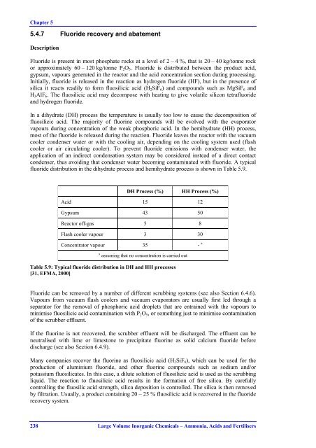
- Page 268 and 269: Chapter 55.4.8 Recovery and abateme
- Page 270 and 271: Chapter 5Operational dataNo informa
- Page 272 and 273: Chapter 55.4.11 Decadmation of H 3
- Page 274 and 275: Chapter 55.4.12 Use of entrainment
- Page 276 and 277: Chapter 5Cross-media effects• dis
- Page 278 and 279: Chapter 5Driving force for implemen
- Page 280 and 281: Chapter 5Cross-media effectsTable 5
- Page 282 and 283: Chapter 5ApplicabilityAt present, o
- Page 285 and 286: Chapter 66 HYDROFLUORIC ACID6.1 Gen
- Page 287 and 288: Chapter 6Component Portion (mass co
- Page 289 and 290: Chapter 66.2.4 Process gas treatmen
- Page 291 and 292: Chapter 66.3 Current emission and c
- Page 293 and 294: Chapter 6Emission of kg/tonne HF Re
- Page 295 and 296: 6.4 Techniques to consider in the d
- Page 297 and 298: Chapter 66.4.2 Energy recovery from
- Page 299 and 300: Chapter 66.4.4 Valorisation of fluo
- Page 301 and 302: Chapter 66.4.6 Scrubbing of tail ga
- Page 303 and 304: 6.4.7 Scrubbing of tail gases: fluo
- Page 305 and 306: Chapter 66.4.8 Abatement of dust em
- Page 307 and 308: Chapter 66.4.9 Waste water treatmen
- Page 309 and 310: Chapter 6Cross-media effects• 5 -
- Page 311 and 312: Chapter 77 NPK AND CN7.1 General in
- Page 313 and 314: Chapter 77.2 Applied processes and
- Page 315 and 316: Chapter 77.2.3 Direct neutralisatio
- Page 317 and 318:
Chapter 7Fluorine compounds origina
- Page 319 and 320:
Chapter7Per tonne productkWh Nm 3 k
- Page 321 and 322:
Chapter7Emission levelmg/Nm 3 ppm k
- Page 323 and 324:
Chapter7Emission levelmg/Nm 3 ppm k
- Page 325 and 326:
7.4 Techniques to consider in the d
- Page 327 and 328:
Chapter7Driving force for implement
- Page 329 and 330:
Chapter7Driving force for implement
- Page 331 and 332:
Chapter7Driving force for implement
- Page 333 and 334:
Chapter7Achieved environmental bene
- Page 335 and 336:
Chapter77.4.6 Recycling warm airDes
- Page 337 and 338:
Chapter77.4.7 Optimising the recycl
- Page 339 and 340:
Chapter7Operational dataThe volume
- Page 341 and 342:
Chapter7Achieved environmental bene
- Page 343 and 344:
Chapter7Achieved environmental bene
- Page 345 and 346:
Chapter77.4.11 Recycling of scrubbi
- Page 347 and 348:
Chapter77.4.12 Waste water treatmen
- Page 349:
Chapter7ParameterLevelmg/Nm 3Phosph
- Page 352 and 353:
Chapter 88.2 Applied processes and
- Page 354 and 355:
Chapter 88.2.1.1 Particle formation
- Page 356 and 357:
Chapter 8Consumption of Per tonne u
- Page 358 and 359:
Chapter 8Per tonne urea Unit Remark
- Page 360 and 361:
Chapter 8Waste water per tonne urea
- Page 362 and 363:
Chapter 8Pollutant Source g/tonne u
- Page 364 and 365:
Chapter 8Plant Emission Amount (ton
- Page 366 and 367:
Chapter 8Achieved environmental ben
- Page 368 and 369:
Chapter 8Operational dataSee Table
- Page 370 and 371:
Chapter 8Operational dataSee Table
- Page 372 and 373:
Chapter 8Driving force for implemen
- Page 374 and 375:
Chapter 88.4.6 Redirecting fines to
- Page 376 and 377:
Chapter 8Existing plantCase 2Revamp
- Page 378 and 379:
Chapter 88.4.8 Heat integration in
- Page 380 and 381:
Chapter 88.4.9 Combined condensatio
- Page 382 and 383:
Chapter 88.4.10 Minimisation of NH
- Page 384 and 385:
Chapter 8Achieved environmental ben
- Page 386 and 387:
Chapter 8Other approaches to proces
- Page 388 and 389:
Chapter 8Achieved environmental ben
- Page 390 and 391:
Chapter 88.5 BAT for Urea and UANBA
- Page 392 and 393:
Chapter 9Country Company LocationBe
- Page 394 and 395:
Chapter 99.2.2 NeutralisationThe ex
- Page 396 and 397:
Chapter 9Scrubbing devices• packe
- Page 398 and 399:
Chapter 99.3 Current emission and c
- Page 400 and 401:
Chapter 9Pollutant mg/Nm 3 g/tonne
- Page 402 and 403:
Chapter 99.4 Techniques to consider
- Page 404 and 405:
Chapter 99.4.2 Recovery of residual
- Page 406 and 407:
Chapter 99.4.3 Energy consideration
- Page 408 and 409:
Chapter 99.4.4 Steam purification a
- Page 410 and 411:
Chapter 99.4.5 Autothermal granulat
- Page 412 and 413:
Chapter 9ApplicabilityIrrigated can
- Page 415 and 416:
Chapter 1010 SUPERPHOSPHATES10.1 Ge
- Page 417 and 418:
Chapter 10Emissionto airEmissionto
- Page 419 and 420:
Chapter 10Input Indirect granulatio
- Page 421 and 422:
Chapter 10Volume5 - 10 m 3 /hourTem
- Page 423 and 424:
Chapter 1010.4.2 Recovery and abate
- Page 425 and 426:
Chapter 1010.4.4 Recycling of scrub
- Page 427 and 428:
Chapter 1111 CONCLUDING REMARKS11.1
- Page 429:
Chapter 11Production of HNO 3 : De-
- Page 432 and 433:
References26 Dipankar Das (1998).
- Page 434 and 435:
References89 Kuiper (2001). "High t
- Page 436 and 437:
References147 Uhde (2006). "The Uhd
- Page 438 and 439:
GlossaryCalculation of steam proper
- Page 440 and 441:
GlossaryIPCCIPPCISO 14001Intergover
- Page 442 and 443:
GlossaryChemical formulasAl 2 O 3Ca
- Page 445 and 446:
Annexes14 ANNEXES14.1 Cost calculat


