Large Volume Inorganic Chemicals - Ammonia ... - ammk-rks.net
Large Volume Inorganic Chemicals - Ammonia ... - ammk-rks.net Large Volume Inorganic Chemicals - Ammonia ... - ammk-rks.net
Chapter 4Two general converter types have been in use extensively in the past:• the brick-arch support and• the cast iron beams and columns design (still very popular in North America).Newer converter types are:• central core tube converters• converters with one or more integrated heat exchangers (with the heat exchanger placed inthe core tube or “wrapped” around the outer shell of the converter vessel).In conventional converters, the shell is generally made of boiler quality steel, with internal bricklining and mostly additional aluminium spraying to protect the material from scaling. A greatadvantage of the brick lined vessel is its high heat capacity, which enables long shutdown timeswithout preheating. The disadvantage is that older brick-arches can be porous and, hence,process gas partially bypasses the intermediate absorber (see also Section 4.4.6 “Replacement ofbrick-arch converters”).Newer converter designs are made of the 304 or 321 type stainless steel to ensure long termstability. The higher cost of stainless steel is compensated by less weight, simply through athinner wall thickness. Figure 4.4 illustrates the design of brick-arch and core tube converters.Catalyst bed 1Catalyst bed 2Catalyst bed 3Catalyst bed 4Figure 4.4: Schematic of a brick-arch converter (left) and a core tube converter (right)These figures are based on [67, Daum, 2000]152 Large Volume Inorganic Chemicals – Ammonia, Acids and Fertilisers
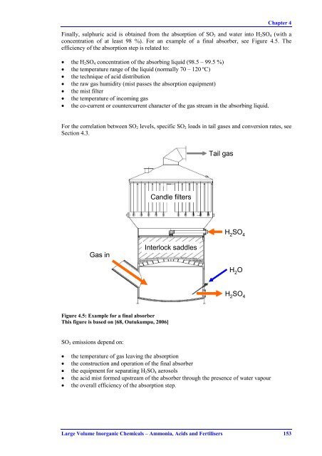
Chapter 4Finally, sulphuric acid is obtained from the absorption of SO 3 and water into H 2 SO 4 (with aconcentration of at least 98 %). For an example of a final absorber, see Figure 4.5. Theefficiency of the absorption step is related to:• the H 2 SO 4 concentration of the absorbing liquid (98.5 – 99.5 %)• the temperature range of the liquid (normally 70 – 120 ºC)• the technique of acid distribution• the raw gas humidity (mist passes the absorption equipment)• the mist filter• the temperature of incoming gas• the co-current or countercurrent character of the gas stream in the absorbing liquid.For the correlation between SO 2 levels, specific SO 2 loads in tail gases and conversion rates, seeSection 4.3.Tail gasCandle filtersH 2SO 4Gas inInterlock saddlesH 2OH 2SO 4Figure 4.5: Example for a final absorberThis figure is based on [68, Outukumpu, 2006]SO 3 emissions depend on:• the temperature of gas leaving the absorption• the construction and operation of the final absorber• the equipment for separating H 2 SO 4 aerosols• the acid mist formed upstream of the absorber through the presence of water vapour• the overall efficiency of the absorption step.Large Volume Inorganic Chemicals – Ammonia, Acids and Fertilisers 153
- Page 129 and 130: Chapter 33.3 Current emission and c
- Page 131 and 132: Chapter 3N 2 O emission levelProces
- Page 133 and 134: Chapter 3N 2 O emission levelProces
- Page 135 and 136: Chapter 3Process typeNO x emission
- Page 137 and 138: Chapter 3Process typeNO x emission
- Page 139 and 140: Chapter 3140120Generation factor %1
- Page 141 and 142: Chapter 33.4.2 Optimisation of the
- Page 143 and 144: Chapter 33.4.3 Alternative oxidatio
- Page 145 and 146: Chapter 33.4.4 Optimisation of the
- Page 147 and 148: Chapter 3Achieved environmental ben
- Page 149 and 150: Chapter 33.4.5 N 2 O decomposition
- Page 151 and 152: Chapter 33.4.6 Catalytic N 2 O deco
- Page 153 and 154: Chapter 3According to [89, Kuiper,
- Page 155 and 156: Chapter 33.4.7 Combined NO x and N
- Page 157 and 158: Chapter 3EconomicsInvestment costs.
- Page 159 and 160: Chapter 3Operational dataSee descri
- Page 161 and 162: Chapter 3NOx removal efficiency in
- Page 163 and 164: Chapter 33.4.10 Addition of H 2 O 2
- Page 165 and 166: Chapter 33.4.11 NO X reduction duri
- Page 167 and 168: Chapter 3Installing a low temperatu
- Page 169 and 170: Chapter 3NO x emission level as NO
- Page 171: Chapter 3Operational dataNo specifi
- Page 174 and 175: Chapter 4Country Company Location C
- Page 176 and 177: Chapter 4Country Company Location C
- Page 178 and 179: Chapter 4Figure 4.2 gives an overvi
- Page 182 and 183: Chapter 4Figure 4.6 gives an impres
- Page 184 and 185: Chapter 44.2.3 Sulphur sources and
- Page 186 and 187: Chapter 44.2.3.5 Non-ferrous metal
- Page 188 and 189: Chapter 4Sulphur source/SO 2 produc
- Page 190 and 191: Chapter 44.3 Current emission and c
- Page 192 and 193: Chapter 410Tail gas specific SO2 lo
- Page 194 and 195: Chapter 4Capacity in tonnesof 100 %
- Page 196 and 197: Chapter 4Capacity in tonnesof 100 %
- Page 198 and 199: Chapter 4SO 2 sourceSpent acid and
- Page 200 and 201: Chapter 4Cross-media effectsWithout
- Page 202 and 203: Chapter 4Achieved environmental ben
- Page 204 and 205: Chapter 44.4.3 Addition of a 5 th b
- Page 206 and 207: Chapter 44.4.4 Application of a Cs-
- Page 208 and 209: Chapter 4EUR/yearWaste gas volume (
- Page 210 and 211: Chapter 44.4.6 Replacement of brick
- Page 212 and 213: Chapter 4EUR/yearWaste gas volume (
- Page 214 and 215: Chapter 4PlantSO 2 sourceInlet SO 2
- Page 216 and 217: Chapter 44.4.10 Combination of SCR
- Page 218 and 219: Chapter 4Achieved environmental ben
- Page 220 and 221: Chapter 4Driving force for implemen
- Page 222 and 223: Chapter 44.4.14 Monitoring of SO 2
- Page 224 and 225: Chapter 4EconomicsCost benefits can
- Page 226 and 227: Chapter 4Energy inputRecovery and l
- Page 228 and 229: Chapter 44.4.16 Minimisation and ab
Chapter 4Finally, sulphuric acid is obtained from the absorption of SO 3 and water into H 2 SO 4 (with aconcentration of at least 98 %). For an example of a final absorber, see Figure 4.5. Theefficiency of the absorption step is related to:• the H 2 SO 4 concentration of the absorbing liquid (98.5 – 99.5 %)• the temperature range of the liquid (normally 70 – 120 ºC)• the technique of acid distribution• the raw gas humidity (mist passes the absorption equipment)• the mist filter• the temperature of incoming gas• the co-current or countercurrent character of the gas stream in the absorbing liquid.For the correlation between SO 2 levels, specific SO 2 loads in tail gases and conversion rates, seeSection 4.3.Tail gasCandle filtersH 2SO 4Gas inInterlock saddlesH 2OH 2SO 4Figure 4.5: Example for a final absorberThis figure is based on [68, Outukumpu, 2006]SO 3 emissions depend on:• the temperature of gas leaving the absorption• the construction and operation of the final absorber• the equipment for separating H 2 SO 4 aerosols• the acid mist formed upstream of the absorber through the presence of water vapour• the overall efficiency of the absorption step.<strong>Large</strong> <strong>Volume</strong> <strong>Inorganic</strong> <strong>Chemicals</strong> – <strong>Ammonia</strong>, Acids and Fertilisers 153


