Accel Ram Jet 1000 CFM - Bowtie Overdrives
Accel Ram Jet 1000 CFM - Bowtie Overdrives
Accel Ram Jet 1000 CFM - Bowtie Overdrives

Create successful ePaper yourself
Turn your PDF publications into a flip-book with our unique Google optimized e-Paper software.
STEP 1With the transmission pan removed and the TV cable disconnected from your carburetor or fuel injection system, locate the partthrottle/detent on the valve body (picture number 1). We have painted the rings orange on this Th-700R4 part throttle detent valve and thealuminum bushing it rides in. This was done for clarity. Picture #1 shows a correctly homed valve. Picture number two shows an incorrectlyhomed valve. Original General Motors TV system plungers will not totally return to their "home" position as shown in picture #1 becausestock systems didn't provide a return spring to mechanically "home" this TV valve assembly. In the original system, the TV valve wasdesigned to home hydraulically once the engine was started. The transmissions hydraulic pump rotor is directly driven by the drive hub of thetorque converter. This drive hub engages the inside rotor drive tangs when its installed into the transmission. The torque converter is boltedto the flexplate in turn bolted to the crankshaft. Consequently, transmissions hydraulic pump rotor turns at engine speed and starts pumpingthe moment the engine is started.Whether your TV system is totally stock or in a transmission that been rebuilt check the TV system using the following method: Push theplunger all the way in until it's even with the face of the aluminum bushing it rides in. Slowly release the plunger. Once it stops moving, checkto see that it's all the way out. Try to pull the plunger out further; if it comes out further, install a TV correction kit. This should be doneregardless of the cause, whether the TV system spring became too short over time or it's just not homing because there's no factory returnspring to push this assembly home. At this point, the cause really makes no difference, since you must now remove the valve body to correctthe problem either way, it's just smart money to install a TV correction system into the valve body while it's off. Once the TV correctionsystem is installed, in the future you will be able to quickly verify whether this system has remained in proper calibration without pulling thepan. This is done by simply hooking up a 0-300 PSI gauge to the pump pressure port and following the pressure test procedure.The pictures above show the part throttle detent plunger in a Th-700R4. Note it has rings machined into the plungers O.D. The plunger in aTh-2004R has a smooth O.D. but the function is the same. Without a correctly calibrated TV system, you cannot expect the transmission tobehave right.
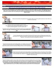
TV CABLE INSTALLATION700R4 TV WIRE CONNECTOR LINK LOCATION2004R TV WIRE CONNECTOR LINK LOCATIONSTEP 1The TV cable is connected to the passenger side of Th-2004R and Th-700R4transmissions at the locations shown in the above pictures. Same side as yourdipstick. The picture at the far left show s the wire link and the TV cable to caseseal. This seal must be placed into the transmission before installation, not onto theend of the TV cable housing! The wire link will be inserted into the hole of theconnector at the transmission end of the TV cable. (See closest picture at left)STEP 2We install a new TV cable seal into every transmission we build. A new seal is alsoprovided with new TV cables. With the transmission in the vehicle, it's very difficultto see if a seal is already installed into the case. Don't try to instal l two seals intothe same hole! The proper method for installing the TV cable is to remove the sealfrom the end of the TV cable, install one into the case, lube the end of the TV cablehousing then slide this freshly lubricated housing into the seal in the case. Stepsthree and four will take you through this picture by picture.STEP 3Slide the bent end of the link through the attachment hole at the end of the TVcable. Gently pull on the opposite end of the TV cable (carburetor/fuel injection end)of the TV cable while feeding the transmission end of the cable housing down intothe transmission seal. Be sure the wire link doesn't slip out while performing thisprocedure.STEP 4Start the end of the cable housing into the rubber seal and pu sh it all the way in using a twisting motion until it'scompletely seated flush with the case. Now line up the bolt hole on the cable housing with the bolt hole on thetransmission case. Install and tighten the bolt. Use caution not to over tighten and break the housing.
STOCK TV CABLE SETUPSTEP 1Insert the TV cable into the base plate bracket until you hear it click into position. Todo this, match the index guide on the TV cable housing, with the notch in the baseplate bracket (red circles in pictures at left). The TV cable will not go in any otherway.STEP 2Check that the two retaining "tabs" on the TV cable housing have spread out and locked the cable into thebase plate bracket. These tabs prevent the cable housing from coming out. (Red circles at right)STEP 3STEP 4Note: The TV Made EZ system shown in the pictures at right is our system for theEdelbrock Pro-Flo 3500 , the cam on your system may not look like this, but all TVMade EZ Evolution Two systems have a similar type cable ball attachment hole inthe cam.The pictures at right illustrate how to connect the TV cable by inserting the ballthrough the provided opening on the cam. Rotating the cable to the rear willprevent it from coming out.Pressing in and holding the 'D' shaped slider release button (pictures at leftand above) the inner cable housing (known as the "slider") will be released andfreely slide back and forth in a range of approximately one inch. Press the "D"button and pull the "slider" all the way to its outermost (forward towards thefront of the engine) position. Positioning the slider all the way out like thismakes the next step, installing of the TV cable "ball" into the hole on the TVMade EZ cam, much easier to accomplish.Once connected, press in the "D" shaped release button, push the "slider" rearward (towards the transmission) as far as it will travel. Whileholding the "slider" rearward, release the "D" shaped button to "fix" the slider in this rearward most position. From the drivers seat position,press the accelerator pedal all the way to the floor. While holding the accelerator pedal to the floor, have your assistant try to rotate thecarburetor/fuel injection linkage further to confirm it's getting W.O.T with the accelerator pedal. If he can rotate the Throttle linkage further,you need to fix the throttle linkage. Once the pressure gauge is connected to the transmissions diagnostic port (See gauge installationinstruction link below), check for instantaneous pressure rise by gently pulling the cable where it leaves the cable housing. Once instantpressure rise is confirmed, You're ready to perform your test drive!STEP 5We strongly recommend you leave the pressure gauge hooked up duringall test driving. It is very educational to observe the operating pressurereactions caused by the TV system. During the test driving we alsorecommend taking along the Allen wrench supplied in the TV Made EZ kit thatfits the cap screw that holds the cam from moving. (Like the one shown withinthe red circles at left) We recommend you start with the cam in the lowerposition (far left picture),Perform a test drive while making mental notes of the shift timing and feel characteristics during light to medium throttle driving. Stop,loosen the attachment bolt, rotate the cam clock wise to the upper position (near left picture), then perform another test drive and notice thedifference in shift timing and feel during light to medium throttle driving with this different set up. We encourage you to freely experimentwith the unlimited number of positions along the cam track until you find the one that gives you the best overall driving characteristics thatmatch your driving style. Be sure to check for instantaneous pressure response with even slight cable movement after each adjustment.These adjustments can be done while the engine is running.
BRAIDED TV CABLE SETUPSTEP 1Install the stainless steel braided cable adapter piece provided in the TV Made EZ kit. This adapter must be mounted on the back side of thebase plate bracket as shown in the pictures above. Secure the adapter to the base plate bracket with the provided 6-32 stainless steel panhead screws and Allen wrench.STEP 2Remove the first adjuster nut, the one indicated by the red arrow in the above left picture. Position the second adjuster nut on the threadedcable housing so the adapter plate will be in the middle of the threaded areas once it's installed into the adapter plate. Slide the cableadjuster housing through the hole in the adapter plate as shown in the pictures at upper right and below left.STEP 3Screw the first adjuster nut back onto the cable adjuster housing. You're now ableto make the proper starting set up of the TV system by screwing these nuts alongthe threaded area of the cable adjuster housing. Moving the position of these twoadjuster nuts along the threaded area of the cable adjuster housing relative to theadapter plate will allow you to "preload" a slight pressure boost. Attach the pressuregauge and hose assembly. Refer to Section 4 for pressure gauge installation.With the transmission full of fluid, engine at idle, TV cable connected to the cam, preset the idle pressure so there's a minimum of two poundsof pressure higher than the disconnected TV cable reading at idle as shown in step 4.STEP 4Note: Edelbrock Pro-Flo 3500 shown in pictures, the cam on your system maynot look like this, but all TV Made EZ Evolution Two systems have this hole inthe cam.The pictures at right illustrate how to connect the TV cable by inserting the ballinto the provided opening on the cam. Once connected, using the adjuster nuts,you need to adjust the cable until you see a 2-4 PSI increase on your pressuregauge above the pressure shown at idle with the TV cable disconnected.Once this preload pressure has been established, even slight gentle forward movement of the TV cable where it exits the TV cable adapterhousing should result in instant pressure response on the gauge. This test must be done by gently pulling the TV cable not movement of theThrottle linkage! The pressure response must be evident with even very small forward movements by the TV cable. If you have one of ourtransmissions, refer to Section 5 for pressure test procedures. Perform the pressure test and call us.STEP 5You are ready to perform your test drive! We recommend the pressuregauge remain hooked up during all test driving. Pay attention to the reactionscaused by the TV system, it is very educational. During the test driving we alsorecommend Allen wrench supplied in the TV Made EZ kit that fits the cap screwshown within the red circles at left. Start with the cam in the lower position (far leftpicture), perform a test drive while making mental notes of the shift timing and feelcharacteristics.Stop, loosen the attachment bolt, rotate the cam clock wise to the upper position (near left picture), then perform another test drive and noticethe difference in shift timing and feel with this set up. You are free to move this cam anywhere along its engineered path with full confidenceas long as you check for instantaneous pressure rise with even slight cable movements.PRESSURE TESTNow that you have your TV Made Ez kit installed, you will need to perform a standard pressure test before you do a test drive. Once youhave done the pressure test, you will need to call in your pressures to verify the set up is correct. If you do not have our transmission, we stillencourage you to proceed to the pressure and drive testing so we can teach you what your pressure readings mean and verify thateverything is in working order, or diagnose any problems that you may have.If you have one of our transmissions, you need to to the pressure tests and call these figures in before you proceed with the test driving.
PRESSURE GAUGE INSTALLATION700R4 PRESSURE PORT LOCATION 2004R PRESSURE PORT LOCATION 4L80E PRESSURE PORT LOCATIONSTEP 1The pressure gauge must be connected to the transmission at the location shownabove. This is a direct fluid passage to the transmissions internal hydraulic pump.This installation will be done while the engine not running. Testing will be donewith the engine running. To hook up the gauge, locate the 1/8" plug on the "DriverSide" of the transmissions bell housing as shown in the above pictures; unscrewthe plug from the transmission.STEP 2Install the 1/8" NPT 90 degree elbow fitting into the transmission. As you tighten thefitting, be sure to end up with the elbow fitting pointing toward the rear of thetransmission. This will ensure that the pressure gauge hose will not interfere withyour shift linkage while you are test driving.STEP 3Screw the pressure gauge hose into the 90 degree fitting. Be sure that it's snuginside of the fitting to prevent leaking. Route the pressure gauge hose above theframe and away from the exhaust. You can now use the gauge under the hood orwhile test driving, routing up through the driver side window.. That's it! We don'trecommend this gauge be installed permanently, it should be removed after the setup and test driving are completed.IMPORTANT NOTESUse of a pressure gauge is the only way to be sure the TV cable system is working correctly. Refer to thepressure check procedure section for a step by step method of setting up this critical system! Adequatepressures during all transmission operations is critical to friction longevity and parts longevity. We highlyrecommend this procedure be followed anytime the TV cable is disconnected or it's relationship to thetransmission is altered in any way. While this system is critical to the very survival of the transmission, makingsure its correctly set up is not difficult to accomplish.
TEST DRIVE PROCEDURESNOTICECAUTION MUST BE EXERCISED DURING THE INITIAL TEST DRIVE. IF YOU FEEL SOMETHING IS NOT CORRECT, STOP AND CALLUS. WE CAN CORRECT WHATEVER THE PROBLEM IS BEFORE ANY DAMAGE IS DONE.DURING ALL THE YEARS OF TEST- DRIVING VEHICLES WE HAVE NEVER DAMAGED A TRANSMISSION DURING THIS PROCESS.IF SOMETHING DOESN'T FEEL RIGHT, STOP THE TEST AND CALL US TO HELP YOU DETERMINE WHAT IS WRONG.TEST DRIVE PROCEDURESIt has been our experience the first hour after start up of a newly built automatic transmission is critical. Realize what we are doing is verysimilar to starting a new engine. Get through this phase and you are well on your way to a long happy life with your new transmission.1. When you are ready to test drive place the selector in the overdrive position. Softly run the transmission through all the forward gears.Come back to a stop and do the same thing at least two more times. This will bring the transmission up to operating temperature. Bring thevehicle back to a full stop.2. Keep the selector in the overdrive position and perform a minimum throttle first to second shift. This will be the slowest vehicle speed youcan get the vehicle to ease into second gear. When the transmission shifts to second you need to aggressively floor the accelerator to makethe transmission perform a second gear to first gear downshift. If the transmission fails to downshift. Terminate the test drive. Carefully returnto your shop and call us.3. Next you perform a minimum throttle (Minimum vehicle speed) third gear into fourth gear. If you have a tachometer this is easy to seewhen this occurs. Without a tachometer you might have to play with the gear selector to determine when you are in fourth gear at minimumvehicle speed. When you are certain that you have the vehicle into forth gear at the slowest vehicle speed, aggressively floor the throttle toforce the transmission to downshift to second, bypassing third in the process. If the transmission fails to perform this test, terminate the testdrive and call us.4. Let the transmission go back into fourth and check for converter lock up. Put your vehicle in light acceleration with your throttle pedal. Holdthat position with your right foot while you gently apply the brake pedal with your left foot. Not enough to apply the brakes but just enough toturn on the brake lights. If your brake pedal disconnect circuit is working; you will feel the engine rpm jump up as the torque converterdisengages. Continue to hold the throttle position with your right foot. When you release the brake pedal with your left foot, the engines' rpmshould drop right back down as the converter re-engages. You must have some acceleration going on while you perform this test or youprobably won't feel the engagement and disengagement when it occurs. Now bring the vehicle back to a complete stop.5. Select manual first gear. <strong>Accel</strong>erate to 3000 rpm and hold that setting for five seconds. When you are sure the transmission will not go intosecond gear on its own, release the throttle pedal back to idle. You should feel a strong compression braking action happening. <strong>Accel</strong>erateback to 3000 rpm.6. Select second gear with the selector. You should get a clean crisp shift into second gear. <strong>Accel</strong>erate up to 3000 rpm and hold that rpmsetting for five seconds. When you are sure the transmission won't shift on it's own into third gear, release the throttle pedal back to the idleposition and check for engine compression braking once again. <strong>Accel</strong>erate back up to 3000 rpm.7. Select manual third gear with the selector. The transmission should cleanly and quickly shift into third gear. Take the engine rpm up to3000, hold it there for five seconds, release the throttle pedal and confirm that you have the correct engine compression braking. Bring thevehicle back to a complete stop.8. Perform a minimum throttle first to second gear up shift, then aggressively floor the accelerator pedal to perform a second gear to first geardownshift. This time hold the throttle pedal to the floor and record the rpm that the transmission automatically up shifts to second gear andthen to third gear. If you don't have a tachometer, the shift points should feel reasonably close to appropriate for passing situations.(Note: You will be asked what your transmission and engine temperatures were at this point)9. Stop the vehicle and open the hood. Feel the return line from your cooling system. Please use some common sense here. Use extremecaution around any moving or hot engine components. Please don't call us complaining of burnt fingers or shredded clothes. When you touchthe return line, do so with caution, use a quick, light tap to determine if the line is scolding hot. You should be able to touch this line withoutburning your hands. Even the outgoing line shouldn't be hot enough to burn you if you touch it momentarily. If you feel very hightemperatures on the return line you should add a cooler. A transmission temperature gauge will help determine what is occurring. If you erroron this topic, please do with too much cooling. The temperature gauge is recommended even if you don't plan to tow. 150 degrees F or lessshould be indicated with a temperature probe (sender) positioned in the pan. The fluid can be seriously overheated if pan temperaturesexceed 150 degrees F. This happens because overheating is occurring in the converter, not the pan. What they don't realize is thetemperature that we are observing is the fluid temperature after it has returned from the cooling system! People are confused about thisbecause they know that Dextron III can withstand higher operating temperatures than 150 degrees F. What they are failing to realize is thegauge is reading the fluid after it has gone through the cooling system. While it is impractical to probe the inside of the torque converter whenit is operating, it's known to be the hottest component in the system. The converter is the heat source and the main reason a cooling systemis essential to automatic transmissions. So we have learned though years of observation this transmission is doing fine at 150 degrees F andoverheating when over that if you are sensing the fluid temperature in the pan.Call with your observations concerning this drive test. Install the remaining pan bolts. (See torque specification sheet) Check for any leaks.These transmissions normally are not "Leakers", but the cooling lines can sometimes be pesky especially at the transmission end. The linescan be difficult to get a wrench on correctly. Recheck the fluid level.