LED RF Signal Meter
LED RF Signal Meter
LED RF Signal Meter
- No tags were found...

You also want an ePaper? Increase the reach of your titles
YUMPU automatically turns print PDFs into web optimized ePapers that Google loves.
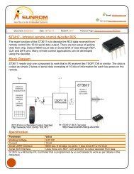
The resolution of the <strong>RF</strong> Power <strong>Meter</strong> is better than +/- 1dB; only near 0dBm power input, theresolution is approximately +/- 2dB.The <strong>RF</strong> input has an impedance of 50 ohms provided by the 53 ohms resistor in parallel withthe internal impedance of the AD8313.For calibration inject first at the input an 800MHz signal at -60dBm and adjust P2 for -6Vreading on the output Voltmeter.After that increase the input level up to 0dBm and adjust P3 for 0V reading on the outputVoltmeter.The slope can be adjusted by the P1 semi-resistor.Careful design of the <strong>RF</strong> input layout should be done for minimizing parasitics which canproduce un-wanted resonances that affects the linearity vs frequency of the log-detector.Tolerance of the resistors is +/-1%.Acalibrated attenuator at the input can be used to increase the maximum input power, withoutdamaging the detector.Correlation of the Input Power to the Output VoltageInputPower[dBm]OutputVoltage[V]-60 -6.0-59 -5.9-58 -5.8-57 -5.7-56 -5.6-55 -5.5-54 -5.4-53 -5.3-52 -5.2-51 -5.1-50 -5.0-49 -4.9-48 -4.8-47 -4.7-46 -4.6-45 -4.5-44 -4.4-43 -4.3-42 -4.2-41 -4.1-40 -4.0-39 -3.9-38 -3.8-37 -3.7