LED RF Signal Meter
LED RF Signal Meter
LED RF Signal Meter
- No tags were found...

Create successful ePaper yourself
Turn your PDF publications into a flip-book with our unique Google optimized e-Paper software.
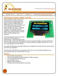
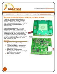
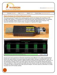
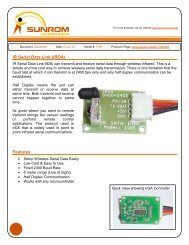
<strong>LED</strong><strong>RF</strong><strong>Signal</strong> <strong>Meter</strong>Select apicturefor larger image.Overview ofthe <strong>LED</strong> <strong>RF</strong> signalmeter. It'sbuiltinto an oldCalifornia AmplifierMMDS downconvertercase. Proper circuit shielding is required for thisproject.Closeupofthe National LM3914 dot/bardisplaydriver.Closeupofthe Analog DevicesAD8313 <strong>RF</strong> logarithmic detectorand power supplyregulation/filtering.
Solder side ofthe <strong>LED</strong>s.Overview showingthe insidesand battery.Power on. The first green<strong>LED</strong> is abatteryindictator, the next two arelitbecauseofbackground<strong>RF</strong> noise.Slightlyclosertothe <strong>RF</strong> source...
BINGO!!! 75 Watts!! Wall-to-wall and tree toptall.Never talktoRadioShackemployees.
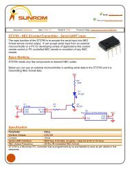
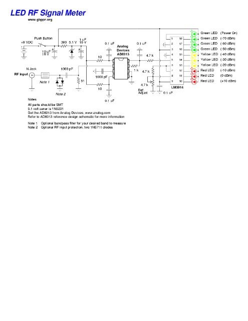
--> ap/xxxxx__<strong>RF</strong>signal strength meter100 MHz-2.5GHz (2008.05.22:1 tech_notes2#39 ad8313#1)Simpledesign basedon Analog Device'sAD8313 chip, providingvisualdisplayofbroadbandsignalstrengthand audio level output ofdemodulated signal.The circuit detects, demodulates the amplitudeand amplifies highfrequencyelectromagnetic emissions(100 MHz to2.5 GHzapprox)for audio frequencyoutput. The main component is the Analog DevicesAD8313 IC:<strong>RF</strong> logarithmic detectorandcontroller, whose output is furtheramplifiedby the TL082 opamp.Circuit diagram:
Or: http://1010.co.uk/images/rssi_strength.pdfPCB and all Kicad/GERBER files:http://1010.co.uk/rssi_strength.tar.gzReferences:http://f6bon.albert.free.fr/Milliwattmetre.htmlhttp://www.analog.com/en/prod/0,,759_847_AD8313,00.htmlhttp://www.turnpoint.net/wireless/cantennahowto.htmlhttp://www.engadget.com/2005/11/15/how-to-build-a-wifi-biquad-dish-antenna/Updated:2008-05-22index xxxxx
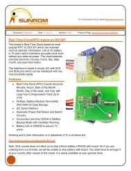
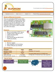
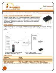
<strong>RF</strong> Power <strong>Meter</strong>using for reading astandard Digital VoltmeterIulian Rosu, YO3DAC /VA3IUL, http://www.qsl.net/va3iul/The <strong>RF</strong> Power <strong>Meter</strong> presented is based on the AD8313 Log Detector manufactured byAnalog Devices.The IC can be ordered as asample direct from ADI (http://www.analog.com/en/), or you cansearch for it in some disabled GSM mobile phones available on the market.In GSM phones AD8313 is used as aLog Detector, part of the Power Control Loop circuit.Generally could be easy identified near the Power Amplifier module.AD8313 is aLogarithmic Detector which can accurately convert an <strong>RF</strong> signal at its input to anequivalent decibel-scaled value at its DC output.The DC output is “linear in dB” with abasic slope of 20mV/dB. The slope can be adjusted in arange from 18mV/dB to 30mV/dB.The linear input range of AD8313 is between -60dBm and 0dBm, which corresponds to aDCoutput between 0.6V to 1.6V (pin 8).The following operational amplifiers (LM324) are translating the DC output range of AD8313(0.6V to 1.6V on Pin nr 8) to ascaled range read by the Voltmeter (-6V to 0V). The scaledrange has aresolution of 100mV/dB.For example the minimum input value (-60dBm) corresponds to aread voltage value of -6.0V,-59dBm corresponds to -5.9V, -58dBm corresponds to -5.8V, and so on up to 0V thatcorresponds to 0dBm (as in the table below).The frequencyrange of AD8313 is between 100MHz to 2.5GHz, but the range that notrequires adynamic slope adjustmentis between 100MHz to 1.4GHz.
The resolution of the <strong>RF</strong> Power <strong>Meter</strong> is better than +/- 1dB; only near 0dBm power input, theresolution is approximately +/- 2dB.The <strong>RF</strong> input has an impedance of 50 ohms provided by the 53 ohms resistor in parallel withthe internal impedance of the AD8313.For calibration inject first at the input an 800MHz signal at -60dBm and adjust P2 for -6Vreading on the output Voltmeter.After that increase the input level up to 0dBm and adjust P3 for 0V reading on the outputVoltmeter.The slope can be adjusted by the P1 semi-resistor.Careful design of the <strong>RF</strong> input layout should be done for minimizing parasitics which canproduce un-wanted resonances that affects the linearity vs frequency of the log-detector.Tolerance of the resistors is +/-1%.Acalibrated attenuator at the input can be used to increase the maximum input power, withoutdamaging the detector.Correlation of the Input Power to the Output VoltageInputPower[dBm]OutputVoltage[V]-60 -6.0-59 -5.9-58 -5.8-57 -5.7-56 -5.6-55 -5.5-54 -5.4-53 -5.3-52 -5.2-51 -5.1-50 -5.0-49 -4.9-48 -4.8-47 -4.7-46 -4.6-45 -4.5-44 -4.4-43 -4.3-42 -4.2-41 -4.1-40 -4.0-39 -3.9-38 -3.8-37 -3.7
-35 -3.5-34 -3.4-33 -3.3-32 -3.2-31 -3.1-30 -3.0-29 -2.9-28 -2.8-27 -2.7-26 -2.6-25 -2.5-24 -2.4-23 -2.3-22 -2.2-21 -2.1-20 -2.0-19 -1.9-18 -1.8-17 -1.7-16 -1.6-15 -1.5-14 -1.4-13 -1.3-12 -1.2-11 -1.1-10 -1.0-9 -0.9-8 -0.8-7 -0.7-6 -0.6-5 -0.5-4 -0.4-3 -0.3-2 -0.2-1 -0.10 0.0home
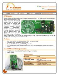
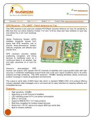
Видеокурсы дляначинающих помикроконтроллерам. ПервыешагиРадио №12012Радиоежегодник№6 2011РадиоЛоцман 122011Электронныесредстванаблюдения иконтрнаблюденияРадиомир КВ иУКВ 12 2011Радиоаматор 112011Простой измеритель СВЧ мощности -65..0 дБм©Barbos &MEGAVOLTUSДавно посещали мысли онеобходимости сборки подобного прибора, но руки не доходили. Вдруг, каквсегда резко понадобилось.Основу измерителя мощности составляет микросхема AD8313 обладающая большим динамическимдиапазоном 60 дБ вширокой полосе частот.Реальные замеры выявили, что вполне сносно данная микросхема работает вдиапазоне мощностейот -60 до -10 дБм (-10 дБм =0,1 мВт, 0дБм =1мВт, 10 дБм =10 мВт, 20 дБм =100 мВт если ктозабыл) при этом рабочий диапазон частот намного шире от 1 МГц до 3 ГГц.Поскольку лень-двигатель прогресса, решено было не заморачиваться смикроконтроллерами иАЦП,аиспользовать готовый китайский тестер. Тестер был разобран, обрезан ипревращен вцифровуюшкалу от -200 до +200 мВ. Как это сделать, можно найти винете.Выходное напряжение AD8313 начинается примерно с0,8 Вольт изаканчивается при типовомвключении примерно на 1,7 Вольт. Для удобства отсчета показаний непосредственно вдБм нужнособрать схему смещающую "ноль". Которая ибыла собрана на ОУ MCP602. Применять вместо нееLM358 не советую, т.к. она плохо работает со слабыми сигналами (хотя тоже будет работать). Номожно поставить LMV358.При монтаже не перегрейте AD8313.Радиоаматор 82011Радиоконструктор №11 2011Радиоконструктор №10 2011яОбновлениУНЧ 038(Редактируется)Готовые статьиFerrum-1827Вот что получилось уменя:Жук на кварце имикросхеме AM&FM 1ИС 2транзистораТелефонныйретронслятор 4ЧастотомерАкустическийгенератор"белого шума"ФиксаторнарушенияМаскирующеепереговорноеустройство.Плата 2-х сторонняя, вторая сторона - сплошная земля. Отверстия на плате перемычками пропаянына землю.Связь покабелямкомпьютернойсетиЭлектроакупунктурныйстимулятор 3СтатистикаЗарегистрированных: 43858Последнимзарегистрирован: alexissersh
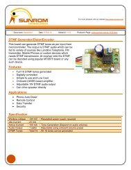
Рекордпосещаемости:440Групппользователей:4Группы:[Admin][Cоучастник][Автор][Модератор]Сейчас насайтеВсего: 194Гостей: 1371Анонимных:Пользователей:56Зарегистрированные:QASAND<strong>RF</strong>errum-1827STG irman CAT5Viktormedvedchuksanya7901 dedFeruz зайцевмихаил_69 alex_p_82 FAIRozborn sat387ioleg73 PaodafАлександр passeverivandurmanMaximcaalexandr56viking99 AcidHFx4bАлександр76diimma 032maxxi 2010olegators68slavikmaStudent79Turata dimasSnepper drotuk1Blech jeka_tmpro-s GANduhabachconvector treck_fm_102.50_mhzkarsel матроскин4477 srg320Nemec ASDFGartemon Pet'kaualeks85 ICAsergeyye sichНастройка:Входной атенюатор из 3-х резисторов отсутствует, вместо него перемычка.Подключаем генератор иподаем 0 дБм на наше устройтство.Первым подстроечником устанавливаем на шкале 0 дБм. Далее аттенюатором генератора уменьшаемсигнал на 30 дБм ивторым подстроечником устанавливаем -30дБм на дисплее. Собственно все.Девайс удобен, точен инеприхотлив вработе. Чувствительность высокая, именно поэтому, если восновном будете налаживать передатчики, то установите на входе атенюатор (на схеме он есть).После чего первым резистором при поданом сигнале сгенератора сместите показания на -10 дБм.Файл платы для Sprint Layout 5.0Через некоторое время пользователь Barbosпредоложил свой вариант реализацииизмерительной головки на основе данноймикросхемы, вот продолжение:Микросхема AD8313 –это высокоточный (+/-1дБ) логарифмический СВЧ детектор.Диапазон частот 100 мГц…3,5 ГГцДинамический диапазон 70 дБТок потребления 13,7 мА (при питании 5 В)Напряжение питания 2,7…5,5 ВЭта микросхема очень удобна для применения вСВЧ измерительных приборах. На VRTP.RU ужеобсуждались приборы сее использованием, например:http://vrtp.ru/index.php?showtopic=4178http://vrtp.ru/index.php?showtopic=12953#http://vrtp.ru/index.php?act=categories&CO...le&article=2410http://vrtp.ru/index.php?act=categories&CO...cle&article=134http://vrtp.ru/index.php?act=categories&CO...le&article=2144Предлагаю еще один вариант СВЧ –измерителя на AD8313. Схема стандартная, по даташиту. Идеязаключается втом, чтобы вынести ВЧ часть вотдельный блок.Самая мощнаяантенна для приема3GРасположение деталей на плате: