KK-23-01 _Ex e II T3-T4_Edycja7 - Cantoni Group
KK-23-01 _Ex e II T3-T4_Edycja7 - Cantoni Group
KK-23-01 _Ex e II T3-T4_Edycja7 - Cantoni Group

You also want an ePaper? Increase the reach of your titles
YUMPU automatically turns print PDFs into web optimized ePapers that Google loves.
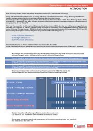
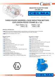
2008-06-02 <strong>KK</strong>-<strong>23</strong>/<strong>01</strong> Edycja 7 Strona 1 z 9Karta KatalogowaCATALOGUE CARDTrójfazowe silniki indukcyjneprzeciwwybuchowe budowy wzmocnionej<strong>II</strong> 2G <strong>Ex</strong> e <strong>II</strong> <strong>T3</strong> – <strong>T4</strong>Three-phase induction explosion-proofincreased safety motors<strong>II</strong> 2G <strong>Ex</strong> e <strong>II</strong> <strong>T3</strong> – <strong>T4</strong>TELEFON: [48] [33] 827-20-00 ÷ 04FAX: [48] [33] 827-20-97 ÷ 99e-mail: indukta@cantonigroup.comhttp://www.indukta.com.pl
2008-06-02 <strong>KK</strong>-<strong>23</strong>/<strong>01</strong> Edycja 7 Strona 2 z 9Silniki szeregu <strong>II</strong> 2G <strong>Ex</strong> e <strong>II</strong> są trójfazowymi,asynchronicznymi silnikami przeciwwybuchowymi,budowy wzmocnionej, w stopniu ochrony IP 55.Są one przystosowane do pracy w niebezpiecznychprzestrzeniach, innych niŜ kopalnie, spowodowanychobecnością wybuchowych gazów, oparów lub mgieł (Grupa<strong>II</strong>).ZastosowanieSilniki naleŜą do urządzeń Grupy <strong>II</strong> Kategorii 2Gprzeznaczonych do pracy w Strefie 1 lub Strefie 2. Silnikimogą być stosowane w przemyśle chemicznym i naftowym.Strefa 1 obejmuje obszary, w których okazjonalnewystępuje atmosfera wybuchowa (nie występuje ciągle).Strefa 2 obejmuje obszary, w których wystąpienieatmosfery wybuchowej jest mało prawdopodobne, ale jeśliwystępuje to bardzo rzadko i tylko na krótki okres.Klasyfikację stref zagroŜonych wybuchem określanorma PN-EN 60079-10. Klasyfikacja powinna zostaćprzeprowadzona przez zespół kompetentnych osób.Charakterystyka silników <strong>Ex</strong>:W silnikach <strong>Ex</strong> zastosowano dodatkowe środkizwiększające bezpieczeństwo wobec moŜliwości powstanianadmiernej temperatury, występowania łuków i iskierwewnątrz i na zewnętrznych częściach silnika – specjalnatabliczka zaciskowa zapewniająca odpowiednie odstępyizolacyjne, atestowany wpust kablowy, dwa zaciskiochronne, wzmocniony układ izolacyjny itd.Zabezpieczenie przeciąŜeniowe silnika musi posiadaćcharakterystykę prądowo-czasową gwarantującą, Ŝe silnikzostanie odłączony od napięcia zasilającego w czasiekrótszym od określonego dla niego czasu t E przy prądzierównym prądowi rozruchowemu silnika; czas t E to czas, wktórym uzwojenie prądu przemiennego podczas przepływuprądu rozruchowego I r = i rn x I n nagrzeje się odtemperatury osiąganej przy pracy znamionowej i przymaksymalnej temperaturze otoczenia, do temperaturygranicznej – czasy te są podane w tabeli parametrówelektrycznych.Normy i atesty:KaŜdy silnik posiada atest producenta, potwierdzającyzgodność wykonania według dokumentacji sporządzonejna postawie najkorzystniejszych wyników badań izatwierdzonej przez Instytut Naukowy KEMA QualityB.V. w Holandii.Silniki są zgodne z normami PN-EN 60079-0, PN-EN60079-7 i dyrektywą europejską ATEX 94/9/EC.The <strong>II</strong> 2G <strong>Ex</strong> e <strong>II</strong> series motors are three phaseasynchronous explosion proof, increased safety andtotally enclosed IP 55 motors. They are adapted foroperating in hazardous areas, other then mining, due tothe presence of explosive gases, vapours or mists (<strong>Group</strong><strong>II</strong>).ApplicationsThe motors belong to devices of <strong>Group</strong> <strong>II</strong> Category 2Gintended to work in Zone 1 and Zone 2. The motors canbe applied in chemical and petroleum industry.Zone 1 covers areas in which occasionaly occurrs anexplosive atmosphere (not constantly).Zone 2 covers areas in which occurrence of an explosiveatmosphere is not likely, but if one should occurr, thenonly rarely and only for a short period.Classification of the zones endangered by explosiondefines the standard EN 60079-10. Classificationshould be carried out by the competent collectivebody.Features of <strong>Ex</strong> motors:In the <strong>Ex</strong> series motors applied additional means toincrease safety in case of appearance of excessivetemperature, occurrence of arcs and sparks inside themotor and on its external parts – special terminal boardensuring proper insulating distances, certified cablegland, two protective terminals, reinforced insulation etc.The overload protection of the motor must have thetime-current characteristic which guarantees that themotor will be disconnected from supply voltage in a timeshorter than specified time t E when the current is equal tostarting current; t E – time in which alternating currentwinding, during flowing of starting currentI r = i rn x I n , will heat up from the temperature of ratedconditions and with maximal ambient temperature to thelimit temperature – these times are in the table of electricparameters.Standards and attestations:Each motor has a certificate of manufacturer, whichconfirms conformity of an execution according to thedocumentation approved by Scientific Institute KEMA –the Netherlands and favourable results of product’s tests.The motors meet requirements of standards EN60079-0, EN 60079-7 and are in accordance with ATEXDirective 94/9/EC.Charakterystyka wykonania: moce znamionowe podane są dla pracy S1, napięcie znamionowe <strong>23</strong>0, 400, 500 [V], częstotliwość napięcia zasilania 50 [Hz], temperatura otoczenia od -20 do +40[°C], wysokość instalowania do 1000 [m] n.p.m., izolacja klasy F, stopień ochrony IP 55,Features: rated outputs for continuous duty, rated voltage <strong>23</strong>0, 400, 500 [V], frequency 50 [Hz], environment temperature -20 to +40[°C], altitude up to 1000 [m] above sea level, insulation class F, protection degree IP 55,
2008-06-02 <strong>KK</strong>-<strong>23</strong>/<strong>01</strong> Edycja 7 Strona 3 z 9 skrzynka zaciskowa z tabliczką 6-zaciskową, aluminiowy przewietrznik, dławnice przeciwwybuchowe <strong>Ex</strong>, zewnętrzny zacisk uziemiający <strong>Ex</strong>, z jednym czopem końcowym wału wg rysunkuwymiarowego, w wielkościach mechanicznych od 90 do 112 istniejemoŜliwość wykonania silników ze skrzynką zaciskowąz lewej lub prawej strony.Wykonania na Ŝyczenia: temperatura otoczenia od -40 do +40[°C], złączka pomocnicza <strong>Ex</strong>, czujniki temperatury typu PTC, z dwoma walcowymi czopami wału wg rysunkuwymiarowego, inne, niestandardowe napięcia od 190V do 690V, silniki do pracy wałkiem w dół (wyposaŜone sądodatkowo w daszek ochronny zabezpieczający osłonęprzewietrznika przed dostępem cieczy i ciał stałych), fabryka wykonuje równieŜ silniki róŜniące się odwykonania podstawowego po uprzednim uzgodnieniuszczegółów konstrukcyjnych i terminów dostaw..Sposób zamawiania: W zamówieniu naleŜy podać pełne określenie typusilnika, moc, napięcie zasilające, prędkość obrotową,klasę temperaturową, formę wykonania oraz inneszczegóły niekatalogowego lub specjalnego wykonania. Przykład:Typ: <strong>II</strong> 2G <strong>Ex</strong> e <strong>II</strong> <strong>T3</strong> Sg 112M-2Moc: 4 kWNapięcie: 400VPrędkość obrotowa: 2875 min -1Klasa temperaturowa: <strong>T3</strong>Forma wykonania: IM 10<strong>01</strong>Producent zastrzega sobie prawo zmian parametrówzawartych w katalogu wynikających z ciągłegodoskonalenia produktów bez wcześniejszegoinformowania.Opis klas temperaturowychSilniki spełniają klasę temperaturową <strong>T3</strong> tzn. maksymalnatemperatura dowolnej części silnika nie przekracza +200°Club klasę temperaturową <strong>T4</strong> tzn. maksymalna temperaturadowolnej części silnika nie przekracza +135°C. terminal box 6 terminal board with 6 terminals. aluminum fan, cable glands <strong>Ex</strong>, external earthing terminal <strong>Ex</strong>, one free shaft extension according to dimensiondrawing, there is a possibility to offer the motors of mechanicalsize 90 and 112 with terminal box mounted in the leftor right side of the motor’frameFeatures on request: environment temperature -40 to +40[°C], auxiliary connector <strong>Ex</strong>, temperature sensors type PTC, two cylindrical shaft extensions according todimension drawing, other, untypical voltages from 190V to 690V, the motors for working in vertical position with theshaft end downwards (The motors are provided withthe special cover which protects the fan cover againstliquids and solids), factory produces various types of motors butconstructional details and delivery time are to beindividual agreedHow to order: In the order there must be clearly given: fulldesignation of the motor, rated output, rated voltage,rated speed, temperatur class, mounting form and allother details for non catalogue execution. <strong>Ex</strong>ample:Type: <strong>II</strong> 2G <strong>Ex</strong> e <strong>II</strong> <strong>T3</strong> Sg 112M-2Rated output: 4 kWVoltage: 400VRpm: 2875Temperature class: <strong>T3</strong>Mounting form: IM 10<strong>01</strong>As part of our development program, we reserve therights to alert or amend any of the specificationswithout giving prior notice.Temperature classesThe motors are designed for temperature class <strong>T3</strong> whichmeans that the maximal temperature of any part of themotor can not exceed +200°C or for temperature class<strong>T4</strong> where maximal temperature can not exceed +135°C.Klasyfikacja klas temperaturowych w zaleŜności od temperatury samozapalenia mieszaniny wybuchowejClassification of temperature classes according to the ignition temperature of explosive mixtureTemperatura samozapaleniamieszaniny wybuchowej w [°C]Ignition temperature of explosivemixture [°C]powyŜej 450Klasy temperaturoweTemperature classesMaksymalna temperatura silnika w °CMaximum temperature of motor [°C]T1 450above 450> 300 T2 300> 200 <strong>T3</strong> 200> 135 <strong>T4</strong> 135
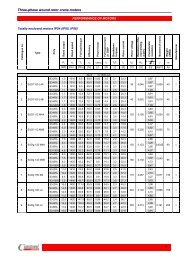
2008-06-02 <strong>KK</strong>-<strong>23</strong>/<strong>01</strong> Edycja 7 Strona 4 z 9PARAMETRY EKSPLOATACYJNE SILNIKÓW <strong>II</strong> 2G <strong>Ex</strong> e <strong>II</strong> <strong>T3</strong>PERFORMANCES OF MOTORS <strong>II</strong> 2G <strong>Ex</strong> e <strong>II</strong> <strong>T3</strong>Typ silnika P n n n η n cos ϕ nType of motorRated outputRatedspeedEfficiencyPowerfactorI 1n przynap. znam.<strong>23</strong>0VFull-loadamps at<strong>23</strong>0VI 1n przynap. znam.400VFull-loadamps at400VI 1n przynap. znam.500VFull-loadamps at500VMMlnLockedrotortorque<strong>II</strong>lnLockedrotorcurrentMMmaxnBreakdowntorqueJMomentofinertia[kW] [HP] [min -1 ] [%] - [A] [A] [A] [-] [-] [-] [kgm 2 ] [s] [kg]2p=2 n s =3000 obr/min no-load rpm=3000Sh 90S-2-<strong>T3</strong> 1,5 2,0 2850 77,8 0,81 6,1 3,5 2,8 2,9 6,0 3,0 0,0<strong>01</strong>3 10,0 12,5Sh 90L-2-<strong>T3</strong> 2,2 3,0 2860 81,7 0,82 8,2 4,7 3,8 3,0 7,1 3,2 0,0020 5,0 15,9Sg 100L-2-<strong>T3</strong> 2,4 3,3 2905 81,7 0,88 8,3 4,8 3,8 2,7 8,3 3,0 0,0048 6,0 22,8Sg 112M-2-<strong>T3</strong> 4,0 5,5 2875 85,5 0,91 13,0 7,5 6,0 2,0 6,5 2,4 0,0080 8,0 33,0Sg 132S-2A-<strong>T3</strong> 5,5 7,5 2915 85,3 0,90 18,1 10,4 8,3 2,4 7,1 2,8 0,<strong>01</strong>50 9,0 57,0Sg 132S-2B-<strong>T3</strong> 7,0 9,4 2920 87,3 0,91 22,1 12,7 10,2 2,5 7,7 3,1 0,<strong>01</strong>90 7,0 76,0Sg 160M-2A-<strong>T3</strong> 11,0 15,0 2920 88,1 0,89 35,0 20,1 16,1 2,3 6,5 2,8 0,0390 5,6 1<strong>01</strong>,0Sg 160L-2-<strong>T3</strong> 16,0 21,4 2940 90,8 0,90 49,2 28,3 22,6 2,8 7,7 3,5 0,0580 7,0 132,0Sg 180M-2-<strong>T3</strong> 18,5 25,0 2945 91,6 0,92 55,3 31,8 25,4 2,3 8,25 3,4 0,0850 13,0 188,02p=4 n s =1500 obr/min no-load rpm=1500Sh 90S-4-<strong>T3</strong> 1,1 1,5 1405 72,9 0,80 4,7 2,7 2,2 2,0 4,65 2,4 0,0027 14,0 12,7Sh 90L-4-<strong>T3</strong> 1,5 2,0 1415 75,5 0,77 6,4 3,7 3,0 2,5 5,3 2,7 0,0028 13,0 15,5Sg 100L-4A-<strong>T3</strong> 2,2 3,0 1425 77,1 0,80 9,0 5,2 4,2 2,4 5,9 2,8 0,0070 9,0 21,9Sg 100L-4B-<strong>T3</strong> 3,0 4,0 1415 78,0 0,81 12,0 6,9 5,5 2,6 5,75 2,9 0,0082 9,0 24,0Sg 112M-4-<strong>T3</strong> 4,0 5,5 1430 82,6 0,85 14,4 8,3 6,6 2,5 6,9 3,0 0,<strong>01</strong>40 7,0 33,0Sg 132S-4-<strong>T3</strong> 5,5 7,5 1455 84,5 0,84 19,3 11,1 8,9 2,2 6,8 2,8 0,0280 7,0 60,0Sg 132M-4-<strong>T3</strong> 7,5 10,0 1450 85,9 0,86 25,4 14,6 11,7 2,3 7,0 2,8 0,0350 5,0 71,0Sg 160M-4-<strong>T3</strong> 11,0 15,0 1460 88,5 0,85 36,7 21,1 16,9 2,2 7,2 3,1 0,0610 7,0 104,0Sg 160L-4-<strong>T3</strong> 15,0 20,0 1460 89,7 0,86 48,7 28,0 22,4 2,3 7,4 3,0 0,0790 6,0 126,0Sg 180M-4-<strong>T3</strong> 18,5 25,0 1470 91,4 0,89 57,4 33,0 26,4 2,8 7,9 2,7 0,1550 5,0 173,0Sg 180L-4-<strong>T3</strong> 22,0 30,0 1465 91,7 0,90 66,6 38,3 30,6 2,8 7,7 2,6 0,1850 5,0 200,02p=6 n s =1000 obr/min no-load rpm=1000Sh 90S-6-<strong>T3</strong> 0,75 1,0 915 69,8 0,73 3,7 2,1 1,7 1,9 3,7 2,1 0,0020 32,0 12,1Sh 90L-6-<strong>T3</strong> 1,10 1,5 920 73,3 0,71 5,2 3,0 2,4 2,2 4,05 2,5 0,0028 33,0 15,5Sg 100L-6-<strong>T3</strong> 1,50 2,0 945 72,5 0,73 7,1 4,1 3,3 2,1 4,5 2,4 0,0090 17,0 21,0Sg 112M-6-<strong>T3</strong> 2,20 3,0 960 81,2 0,77 8,9 5,1 4,1 2,3 5,9 2,7 0,<strong>01</strong>90 19,0 32,0Sg 132S-6-<strong>T3</strong> 3,00 4,0 945 79,7 0,80 11,8 6,8 5,4 2,1 5,3 2,8 0,0240 18,0 52,0Sg 132M-6A-<strong>T3</strong> 4,00 5,5 950 82,9 0,82 14,8 8,5 6,8 2,3 6,1 2,9 0,0320 14,0 64,0Sg 132M-6B-<strong>T3</strong> 5,50 7,5 950 83,3 0,82 20,2 11,6 9,3 2,7 6,4 3,4 0,0390 8,0 71,0Sg 160M-6-<strong>T3</strong> 7,50 10,0 960 86,3 0,80 27,3 15,7 12,6 2,2 6,5 2,8 0,0680 10,0 99,0Sg 160L-6-<strong>T3</strong> 11,00 15,0 960 87,5 0,82 38,3 22,0 17,6 2,3 6,8 3,3 0,0980 8,0 126,0Sg 180L-6-<strong>T3</strong> 13,5 18,1 980 89,3 0,82 46,3 26,6 21,3 3,2 6,7 2,4 0,2210 8,0 169,0t Et EMasaIM B3WeightIM B3
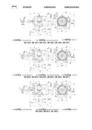
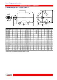
2008-06-02 <strong>KK</strong>-<strong>23</strong>/<strong>01</strong> Edycja 7 Strona 7 z 9Wymiary montaŜowe silników kołnierzowychMounting dimensions for flange-mounted motorsTyp D,DA E,EA F,FA GA,GC M N P S TType[mm]SKh 90S ... 24j6 50 8h9 27,0 165 130j6 200 12 3,5SKh 90L ... 24j6 50 8h9 27,0 165 130j6 200 12 3,5SKg 100L ... 28j6 60 8h9 31,0 215 180j6 250 15 4,0SKg 112M ... 28j6 60 8h9 31,0 215 180j6 250 15 4,0SKg 132S ... 38k6 80 10h9 41,0 265 <strong>23</strong>0j6 300 15 4,0SKg 132S-2B 38k6 80 10h9 41,0 265 <strong>23</strong>0j6 300 15 4,0SKg 132M ... 38k6 80 10h9 41,0 265 <strong>23</strong>0j6 300 15 4,0SKg 160M ... 42k6 110 12h9 45,0 300 250j6 350 19 5,0SKg 160L ... 42k6 110 12h9 45,0 300 250j6 350 19 5,0SKg 180M ... 48k6 110 14h9 51,5 300 250j6 350 19 5,0SKg 180L ... 48k6 110 14h9 51,5 300 250j6 350 19 5,0Wymiary gabarytowe silników kołnierzowychOverall dimensions for flange-mounted motorsTyp AC BL d1,d2 HB L LA LC q Md ŁoŜysko nrType [mm] Bearing NoSKh 90S ... 185 15 M8 130 305 8 360 - M 20 x 1,5 6205 2ZSKh 90L ... 185 15 M8 130 330 8 385 - M 20 x 1,5 6205 2ZSKg 100L ... 206 20 M10 140 376 11 441 - M 20 x 1,5 6206 2ZSKg 112M ... 245 20 M10 164 384 12 449 257 M 25 x 1,5 6306 2ZSKg 132S ... 274 40 M12 178 463 12 549 284 M 25 x 1,5 6308 2ZSKg 132S-2B 274 40 M12 178 5<strong>01</strong> 12 587 284 M 25 x 1,5 6308 2ZSKg 132M ... 274 40 M12 178 5<strong>01</strong> 12 587 284 M 25 x 1,5 6308 2ZSKg 160M ... 3<strong>23</strong> 40 M16 210 612 13 738 350 M 40 x 1,5 6309 2ZSKg 160L ... 3<strong>23</strong> 40 M16 210 656 13 782 350 M 40 x 1,5 6309 2ZSKg 180M-4...SKg 180L-6...360 40 M16 228 705 13 825 358 M 40 x 1,5 6311 2ZSKg 180M-2...SKg 180L-4...360 40 M16 228 756 13 876 358 M 40 x 1,5 6311 2ZFormy wykonania: IM 30<strong>01</strong>, IM 3<strong>01</strong>1, IM 3031 - wg IEC 34-7, PN-EN 60034-7 (IM 3<strong>01</strong>1 – z daszkiem ochronnym) IM B5, IM V1, IM V3 - wg IEC 34-7, PN-EN 60034-7 (IM V1 – z daszkiem ochronnym)Mountimg forms: IM 30<strong>01</strong>, IM 3<strong>01</strong>1, IM 3031 - per IEC 34-7, EN 60034-7 (IM 3<strong>01</strong>1 – with protective cap) IM B5, IM V1, IM V3 - per IEC 34-7, EN 60034-7 (IM V1 – with protective cap)
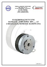
2008-06-02 <strong>KK</strong>-<strong>23</strong>/<strong>01</strong> Edycja 7 Strona 8 z 9Wymiary montaŜowe silników kołnierzowych na łapachMounting dimensions for foot-flange-mounted motorsTyp A B C D,DA E,EA F,FA GA,GC H K M N P S TType[mm]SLh 90S ... 140 100 56 24j6 50 8h9 27,0 90 10 165 130j6 200 12 3,5SLh 90L ... 140 125 56 24j6 50 8h9 27,0 90 10 165 130j6 200 12 3,5SLg 100L ... 160 140 63 28j6 60 8h9 31,0 100 12 215 180j6 250 15 4,0SLg 112M ... 190 140 70 28j6 60 8h9 31,0 112 12 215 180j6 250 15 4,0SLg 132S ... 216 140 89 38k6 80 10h9 41,0 132 12 265 <strong>23</strong>0j6 300 15 4,0SLg 132S-2B 216 140 89 38k6 80 10h9 41,0 132 12 265 <strong>23</strong>0j6 300 15 4,0SLg 132M ... 216 178 89 38k6 80 10h9 41,0 132 12 265 <strong>23</strong>0j6 300 15 4,0SLg 160M ... 254 210 108 42k6 110 12h9 45,0 160 15 300 250j6 350 19 5,0SLg 160L ... 254 254 108 42k6 110 12h9 45,0 160 15 300 250j6 350 19 5,0SLg 180M ... 279 241 121 48k6 110 14h9 51,5 180 15 300 250j6 350 19 5,0SLg 180L ... 279 279 121 48k6 110 14h9 51,5 180 15 300 250j6 350 19 5,0Wymiary gabarytowe silników kołnierzowych na łapachOverall dimensions for foot-flange-mounted motorsTyp AA AB BB BL CA d1,d2 HA HD L LA LC q Md ŁoŜysko nrType [mm] Bearing NoSLh 90S ... 50 170 153 15 104 M8 10 220 305 8 360 - M 20 x 1,5 6205 2ZSLh 90L ... 50 170 153 15 104 M8 10 220 330 8 385 - M 20 x 1,5 6205 2ZSLg 100L ... 45 200 172 20 116 M10 14 240 376 11 441 - M 20 x 1,5 6206 2ZSLg 112M ... 54 <strong>23</strong>0 174 20 119 M10 14 276 384 12 449 257 M 25 x 1,5 6306 2ZSLg 132S ... 56 278 182 40 160 M12 16 310 463 12 549 284 M 25 x 1,5 6308 2ZSLg 132S-2B 56 278 220 40 198 M12 16 310 5<strong>01</strong> 12 587 284 M 25 x 1,5 6308 2ZSLg 132M ... 56 278 220 40 160 M12 16 310 5<strong>01</strong> 12 587 284 M 25 x 1,5 6308 2ZSLg 160M ... 60 305 256 40 200 M16 20 370 612 13 738 350 M 40 x 1,5 6309 2ZSLg 160L ... 60 305 300 40 200 M16 20 370 656 13 782 350 M 40 x 1,5 6309 2ZSLg 180M-4...SLg 180L-6...SLg 180M-2...SLg 180L-4...70 350 320 40 243 M16 26 408 705 13 825 358 M 40 x 1,5 6311 2Z70 350 320 40 256 M16 26 408 756 13 876 358 M 40 x 1,5 6311 2ZWymiar AB dla silników wielkości 132 z łapami odlewanymi wraz z korpusem wynosi 260 mm.As to motors of size „132” the dimension AB amounts to 260 mm in case the feet are together with frame casted.Formy wykonania: IM 20<strong>01</strong>, IM 2<strong>01</strong>1, IM 2031 - wg IEC 34-7, PN-EN 60034-7 (IM 2<strong>01</strong>1 – z daszkiem ochronnym) IM B35, IM V15, IM V36 - wg IEC 34-7, PN-EN 60034-7 (IM V15 – z daszkiem ochronnym)Mountimg forms: IM 20<strong>01</strong>, IM 2<strong>01</strong>1, IM 2031 - per IEC 34-7,EN 60034-7 (IM 2<strong>01</strong>1 – with protective cap) IM B35, IM V15, IM V36 - per IEC 34-7, EN 60034-7 (IM V15 – with protective cap)
2008-06-02 <strong>KK</strong>-<strong>23</strong>/<strong>01</strong> Edycja 7 Strona 9 z 9Wymiary montaŜowe silników z tarczą kołnierzową B14Mounting dimensions for motors with flange B14TypTypeD,DA E,EA F,FA GA,GCSKh 90 ... 24j6 50 8h9 27,0SKg 100 ... 28j6 60 8h9 31,0SKg 112 ... 28j6 60 8h9 31,0SKg 132 ... 38k6 80 10h9 41,0SKg 160 … 42k6 110 12h9 45,0B14KołnierzFlangeM N P S LA T[mm]FT130/C160 130 110j6 160 M8 10 3,5FT115/C140 115 95j6 140 M8 10 3,0FT165/C200 165 130j6 200 M10 12 3,5FT130/C160 130 110j6 160 M8 12 3,5FT165/C200 165 130j6 200 M10 12 3,5FT130/C160 130 110j6 160 M8 12 3,5FT215/C250 215 180j6 250 M12 12 4,0FT165/C200 165 130j6 200 M10 12 3,5FT265/C300 265 <strong>23</strong>0j6 300 M12 13 4,0FT215/C250 215 180j6 250 M12 20 4,0Wymiary gabarytowe silników z tarczą kołnierzową B14Overall dimensions for motors with flange B14Typ AC BL d1,d2 HB L LC qType [mm] MdŁoŜysko nrBearingNoSKh 90S ... 185 15 M8 130 305 360 - M 20 x 1,5 6205 2ZSKh 90L ... 185 15 M8 130 330 385 - M 20 x 1,5 6205 2ZSKg 100L ... 206 20 M10 140 376 441 - M 20 x 1,5 6206 2ZSKg 112M ... 245 20 M10 164 384 449 257 M 25 x 1,5 6306 2ZSKg 132S ... 274 40 M12 178 463 549 284 M 25 x 1,5 6308 2ZSKg 132S-2B 274 40 M12 178 5<strong>01</strong> 587 284 M 25 x 1,5 6308 2ZSKg 132M ... 274 40 M12 178 5<strong>01</strong> 587 284 M 25 x 1,5 6308 2ZSKg 160M … 3<strong>23</strong> 40 M16 210 612 738 350 M 40 x 1,5 6309 2ZSKg 160L … 3<strong>23</strong> 40 M16 210 656 782 350 M 40 x 1,5 6309 2ZWymiary silników kołnierzowych na łapach IM B34 (oprócz tarczy kołnierzowej) –patrz tabele dla IM B35 na stronie 6Dimensions for foot-flange motors IM B34 (except flange shield) – see tables for IM B35 on page 6Wymiar AB dla silników wielkości 132 z łapami odlewanymi wraz z korpusem wynosi 260 mm.As to motors of size „132” the dimension AB amounts to 260 mm in case the feet are together with frame casted.Formy wykonania: IM 36<strong>01</strong>, IM 3611, IM 3631 - wg IEC 34-7, PN-EN 60034-7 IM B14 - wg IEC 34-7, EN 60034-7Mounting forms: IM 36<strong>01</strong>, IM 3611, IM 3631 - per PN-EN 60034-7 IM B14 - per IEC 34-7, EN 60034-7