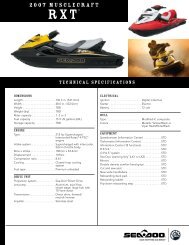
engine, rotax 1503 4-tec - Sea-Doo.net
engine, rotax 1503 4-tec - Sea-Doo.net
engine, rotax 1503 4-tec - Sea-Doo.net
- No tags were found...

Create successful ePaper yourself
Turn your PDF publications into a flip-book with our unique Google optimized e-Paper software.
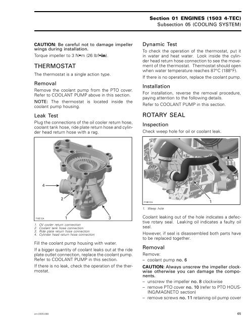
Section 01 ENGINES (<strong>1503</strong> 4-TEC)Subsection 05 (COOLING SYSTEM)CAUTION: Be careful not to damage impellerwings during installation.Torque impeller to 3 N•m (26lbf•in).THERMOSTATThe thermostat is a single action type.RemovalRemove the coolant pump from the PTO cover.RefertoCOOLANTPUMPaboveinthissection.NOTE: The thermostat is located inside thecoolant pump housing.Leak TestPlug the connections of the oil cooler return hose,coolant tank hose, ride plate return hose and cylinderheadreturnhosewitharag.Dynamic TestTo check the operation of the thermostat, put itin water and heat water. Look inside the cylinderhead return hose connection to see the movementof the thermostat. Thermostat should openwhen water temperature reaches 87°C (188°F).If there is no operation, replace the coolant pump.InstallationFor installation, reverse the removal procedure,paying attention to the following details.RefertoCOOLANTPUMPinthissection.ROTARY SEALInspectionCheck weep hole for oil or coolant leak.42F18E1CA1. Weep hole1F18E12A 131. Oil cooler return connection2. Coolant tank hose connection3. Ride plate return hose connection4. Cylinder head return hose connectionFill the coolant pump housing with water.If a bigger quantity of coolant leaks out at the rideplate outlet connection, replace the coolant pump.Refer to COOLANT PUMP in this section.If there is no leak, check the operation of the thermostat.Coolant leaking out of the hole indicates a defectiverotary seal. Leaking oil indicates a faulty oilseal.However, if seal is disassembled both parts haveto be replaced together.RemovalRemove:– coolant pump no. 6CAUTION: Always unscrew the impeller clockwiseotherwise you can damage the components.– unscrew the impeller no. 8 clockwise– remove PTO cover no. 10 (refer to PTO HOUS-ING/MAGNETO section)– remove screws no. 11 retaining oil pump coversmr2005-088 65