engine, rotax 1503 4-tec - Sea-Doo.net
engine, rotax 1503 4-tec - Sea-Doo.net
engine, rotax 1503 4-tec - Sea-Doo.net
- No tags were found...

You also want an ePaper? Increase the reach of your titles
YUMPU automatically turns print PDFs into web optimized ePapers that Google loves.
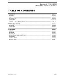
INTRODUCTIONTYPICAL PAGESub-title with partname(s) fromexploded view.Section 06 FUEL SYSTEMSubsection 03 (CARBURETORS)Title indicates mainprocedure to becarried-out.Service tool to beused to perform acertain procedure.Title in italic indicates aparticular procedureconcerning a model.CARBURETOR REMOVALTo remove carburetors from <strong>engine</strong>, proceed as follows:Remove air vent tube support.Unlock retaining slides holding air intake silencer base.Remove air intake silencer base from watercraft.Remove screws holding flame arrester base supportto cylinder head cover.Unscrew base retaining screws then remove base fromcarburetors and move to front of watercraft.Turn the valve to OFF position.NOTE: For fuel line removal, use pliers (P/N 295000 054).Disconnect pulse line from fuel pump.Disconnect fuel fuel supply line from fuel pump.Disconnect fuel return line.Disconnect oil injection pump cable, throttle cable andchoke cable.XP Model OnlyRemove screws no. 6 and lock washers no. 7 retainingcarburetors.DISASSEMBLY AND INSPECTIONInspect parts for corrosion dammage (shaft, butterfly,spring screw, check valve housing, etc.).DiaphragmPUMP DIAPHRAGM LEAK TESTUsing a suitable pump gauge tester, perform the followingtest proceeding as follows:- Install pump gauge tester (P/N 295 000 083) on pulsenipple.- Pump tester until it reaches 28 kPa (4 PSI).1ASub-sub-title incapital indicates aparticular testing,adjustment orrepair procedure.Illustrationalways followstext it ispertained to.Sub-sub-title in thiscase indicates thatparticular procedurefor XP is finished, sofrom this point, allothers models areconcerned.All Others ModelsRemove 4 bolts no. 8 and lock washers no. 12 fromrotary valve cover then move carburetors and rotaryvalve cover on top of <strong>engine</strong>.NOTE: When removing rotary valve cover , payattention that the rotary valve stay in place, other-wiseit must be timed.Remove carburetors from intake manifold.Disconnect fuel bypass line between carburetors (twincarburetors).Remove carburetor(s) from rotary valve cover.F01F0XBTYPICAL1221 2Diaphragm must stand pressure for 10 seconds. Ifpressure drops, replace diaphragm.“TYPICAL” mentionindicates a generalview which does notrepresent full detail.Numbered step areused to give asequence to beperfomed.Letters are used forany measures.31Bold numbers in thetext refer to the partsshown in the explodedview at the beginningof the subsection.Numbers are usedfor description ofcomponents.F01A0BTsmr2005-002VII