engine, rotax 1503 4-tec - Sea-Doo.net
engine, rotax 1503 4-tec - Sea-Doo.net
engine, rotax 1503 4-tec - Sea-Doo.net
- No tags were found...

You also want an ePaper? Increase the reach of your titles
YUMPU automatically turns print PDFs into web optimized ePapers that Google loves.
2005Engine Shop ManualROTAX ® <strong>1503</strong> 4-TECENGINES
Legal deposit:National Library of QuebecNational Library of Canada 2005All rights reserved. No parts of this manual may be reproduced in any form without the prior writtenpermission of Bombardier Recreational Products Inc. (BRP).©Bombardier Recreational Products Inc. (BRP) 2005Technical PublicationsBombardier Recreational Products Inc. (BRP)Valcourt (Quebec) CanadaPrintedinCanada®TMRegistered trademarks of Bombardier Recreational Products Inc. (BRP) or its affiliates.* Trademark of Bombardier Inc. used under license.SEA-DOO ®BOMBARDIER LUBE ®<strong>Sea</strong>-<strong>Doo</strong> Synthetic Grease<strong>Sea</strong>-<strong>Doo</strong> ® Learning Key TMDESS TMRotax ®TOPS TMThis document contains the trademarks of the following companies:Loctite ® is a trademark of Loctite CorporationSnap-on ® is a trademark of Snap-on Tools CorporationMolykote © is a trademark of Dow Corning CorporationAMP © is a trademark of Tyco Electronics Corporation
TABLE OF CONTENTSSAFETY NOTICE....................................................................................IIIINTRODUCTION ................................................................................... IVGENERAL INFORMATION.......................................................................................... IVENGINE EMISSIONS INFORMATION ............................................................................ IVENGINE IDENTIFICATION NUMBER (E.I.N.) .................................................................... IVTIGHTENING TORQUES ........................................................................................... IVARRANGEMENT OF THIS MANUAL, ILLUSTRATIONS AND PROCEDURES ............................. V01 ENGINES (<strong>1503</strong> 4-TEC)01 – LEAK TEST ...................................................................................................... 1PROCEDURES .................................................................................................. 1PREPARATION ........................................................................................................ 1PROCEDURE .......................................................................................................... 2DIAGNOSIS............................................................................................................ 3POSSIBLE ENGINE LEAKAGE AREA................................................................................ 3ASSEMBLY ............................................................................................................ 402 – INTAKE MANIFOLD AND SUPERCHARGER............................................................... 5INSPECTION (PARTS ASSEMBLED)................................................................................ 10REMOVAL ............................................................................................................ 12DISASSEMBLY ....................................................................................................... 17INSPECTION (PARTS DISASSEMBLED) ........................................................................... 20ASSEMBLY ........................................................................................................... 21INSTALLATION ....................................................................................................... 2603 – PTO HOUSING AND MAGNETO .......................................................................... 29GENERAL...................................................................................................... 31PROCEDURES ................................................................................................ 31PTO HOUSING ....................................................................................................... 31PTO SEAL............................................................................................................. 34COUPLING............................................................................................................ 35STATOR............................................................................................................... 35ROTOR AND TRIGGER WHEEL .................................................................................... 36RING GEAR........................................................................................................... 37STARTER DRIVE ASS'Y.............................................................................................. 38OIL SPRAY NOZZLE ................................................................................................. 3904 – LUBRICATION SYSTEM..................................................................................... 41GENERAL...................................................................................................... 45PROCEDURES ................................................................................................ 45ENGINE OIL PRESSURE............................................................................................. 45PTO OIL STRAINER.................................................................................................. 46SUCTION PUMP OIL STRAINER.................................................................................... 47ENGINE OIL PRESSURE REGULATOR............................................................................. 49OIL PRESSURE PUMP............................................................................................... 51OIL SUCTION PUMP................................................................................................. 54OIL SEPARATOR COVER............................................................................................ 57TOPS VALVE.......................................................................................................... 58OIL COOLER ......................................................................................................... 5805 – COOLING SYSTEM .......................................................................................... 61GENERAL...................................................................................................... 63PROCEDURES ................................................................................................ 63COOLANT PUMP .................................................................................................... 63COOLANT PUMP IMPELLER ....................................................................................... 64I
TABLE OF CONTENTSTHERMOSTAT........................................................................................................ 65ROTARY SEAL........................................................................................................ 6506 – CYLINDER HEAD............................................................................................. 69GENERAL...................................................................................................... 71PROCEDURES ................................................................................................ 71SPARK PLUG ......................................................................................................... 71EXHAUST MANIFOLD............................................................................................... 71VALVE COVER........................................................................................................ 72ROCKER ARM........................................................................................................ 73CAMSHAFT TIMING GEAR.......................................................................................... 76TIMING CHAIN....................................................................................................... 77CYLINDER HEAD..................................................................................................... 78CAMSHAFT........................................................................................................... 79VALVE SPRING ....................................................................................................... 80VALVE ................................................................................................................. 8207 – CYLINDER BLOCK............................................................................................ 89GENERAL...................................................................................................... 92PROCEDURES ................................................................................................ 92TIMING CHAIN....................................................................................................... 92CHAIN TENSIONER.................................................................................................. 92PISTON/CONNECTING ROD........................................................................................ 93PISTON RINGS ....................................................................................................... 98CRANKSHAFT ........................................................................................................ 99BALANCER SHAFT................................................................................................. 104CYLINDER BLOCK................................................................................................. 10708 – TECHNICAL SPECIFICATIONS ............................................................................ 113II
SAFETY NOTICESAFETY NOTICEThis manual has been prepared as a guide to correctly service and repair the Rotax ® <strong>1503</strong> 4-TEC <strong>engine</strong>s.This edition was primarily published to be used by <strong>tec</strong>hnicians who are already familiar with all serviceprocedures relating to BRP products. Mechanical <strong>tec</strong>hnicians should attend training courses given byBRP Training Dept.Please note that the instructions will apply only if proper hand tools and special service tools are used.This ENGINE SHOP MANUAL uses <strong>tec</strong>hnical terms which may be slightly different from the ones usedin the PARTS CATALOG.It is understood that this manual may be translated into another language. In the event of any discrepancy,the English version shall prevail.The content depicts parts and/or procedures applicable to the particular product at time of writing. Serviceand Warranty Bulletins may be published to update the content of this manual. Make sure to readand understand these.In addition, the sole purpose of the illustrations throughout the manual, is to assist identification of thegeneral configuration of the parts. They are not to be interpreted as <strong>tec</strong>hnical drawings or exact replicasof the parts.The use of BRP parts is most strongly recommended when considering replacement of any component.Dealer and/or distributor assistance should be sought in case of doubt.The <strong>engine</strong> identified in this document should not be utilized on product(s) other than those for which itwas designed. WARNINGUnless otherwise specified, <strong>engine</strong> should be turned OFF and cold for all maintenance and repairprocedures.This manual emphasizes particular information denoted by the wording and symbols: WARNINGIdentifies an instruction which, if not followed, could cause serious personal injury including possibilityof death.CAUTION: Denotes an instruction which, if not followed, could severely damage <strong>engine</strong> components.NOTE: Indicates supplementary information needed to fully complete an instruction.Although the mere reading of such information does not eliminate the hazard, your understanding of theinformation will promote its correct use. Always use common shop safety practice.BRP disclaims liability for all damages and/or injuries resulting from the improper use of the contents.We strongly recommend that any services be carried out and/or verified by a highly skilled professionalmechanic. It is understood that certain modifications may render use of the <strong>engine</strong> illegal under existingfederal, provincial and state regulations.SMR2004-001 ENIII
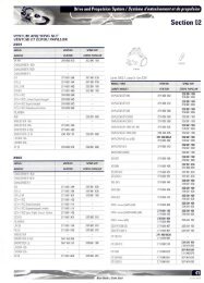
INTRODUCTIONINTRODUCTIONGENERAL INFORMATIONThis ENGINE SHOP MANUAL covers the Rotax<strong>1503</strong> 4-TEC <strong>engine</strong>. It should be used in conjunctionwith the appropriate VEHICLE SHOP MANU-AL.The information and component/system descriptionscontained in this manual are correct at timeof writing. BRP however, maintains a policy ofcontinuous improvement of its products withoutimposing upon itself any obligation to install themon products previously manufactured.BRP reserves the right at any time to discontinueor change specifications, designs, features, modelsor equipment without incurring obligation.This SHOP MANUAL uses <strong>tec</strong>hnical terms whichmay be different from the ones of the PARTS CAT-ALOGS.When ordering parts always refer to the specificmodel PARTS CATALOGS.ENGINE EMISSIONSINFORMATIONRefer to the appropriate VEHICLE SHOP MANU-AL.ENGINE IDENTIFICATIONNUMBER (E.I.N.)The Engine Identification Number is located onfront end of the <strong>engine</strong>.F18D03A1. Engine Identification Number (E.I.N.)TIGHTENING TORQUESTighten fasteners to torque mentioned in explodedviews and/or text. WARNINGTorque wrench tightening specificationsmust strictly be adhered to. Locking devices(ex.: locking tabs, elastic stop nuts, self-lockingfasteners, etc.) must be installed orreplaced with new ones, where specified. Ifthe efficiency of a locking device is impaired,it must be renewed.1IVsmr2005-002
INTRODUCTIONARRANGEMENT OF THISMANUAL, ILLUSTRATIONSAND PROCEDURESThe manual is divided into many major sections asyou can see in the main table of contents at thebeginning of the manual.Several sections are divided in various subsections.There is a table of contents at the beginningof many sections.The illustrations show the typical construction ofthe different assemblies and, in all cases, may notreproduce the full detail or exact shape of the partsshown, however, they represent parts which havethe same or a similar function.CAUTION: These watercraft are designed withparts dimensioned mostly in the metric system.However some components may be fromthe imperial system. When replacing fasteners,make sure to use only those recommendedby BRP.As many of the procedures in this manual are interrelated,we suggest, that before undertaking anytask, you read and thoroughly understand the entiresection or subsection in which the procedureis contained.A number of procedures throughout the book requirethe use of special tools. Before undertakingany procedure, be sure that you have on hand allthe tools required, or approved equivalents.smr2005-002V
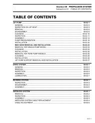
INTRODUCTIONTYPICAL PAGEPage headingindicates sectionand subsectiondetailed.Subsection titleindicatesbeginning of thesubsection.Subsection 04(MAGNETO SYSTEM)Italic sub-titleabove explodedview indicatepertaining models.Drop representsa liquid productto be applied to asurface. In this caseLoctite 243 toscrew threads.Loctite243Exploded viewassists you inidentifying parts andrelated positions.Loctite243Loctite243Loctite243Dotted boxcontains parts ofa particularmodel or anexploded view.Loctite243Bold face numberindicates specialprocedureconcerning this part.Loctite648145 N•m(107 lbf•ft)Anti-seizelubricantIllustration numberfor publishingprocess.F01D4WS30Page numberF01A0CTVIsmr2005-002
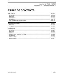
INTRODUCTIONTYPICAL PAGESub-title with partname(s) fromexploded view.Section 06 FUEL SYSTEMSubsection 03 (CARBURETORS)Title indicates mainprocedure to becarried-out.Service tool to beused to perform acertain procedure.Title in italic indicates aparticular procedureconcerning a model.CARBURETOR REMOVALTo remove carburetors from <strong>engine</strong>, proceed as follows:Remove air vent tube support.Unlock retaining slides holding air intake silencer base.Remove air intake silencer base from watercraft.Remove screws holding flame arrester base supportto cylinder head cover.Unscrew base retaining screws then remove base fromcarburetors and move to front of watercraft.Turn the valve to OFF position.NOTE: For fuel line removal, use pliers (P/N 295000 054).Disconnect pulse line from fuel pump.Disconnect fuel fuel supply line from fuel pump.Disconnect fuel return line.Disconnect oil injection pump cable, throttle cable andchoke cable.XP Model OnlyRemove screws no. 6 and lock washers no. 7 retainingcarburetors.DISASSEMBLY AND INSPECTIONInspect parts for corrosion dammage (shaft, butterfly,spring screw, check valve housing, etc.).DiaphragmPUMP DIAPHRAGM LEAK TESTUsing a suitable pump gauge tester, perform the followingtest proceeding as follows:- Install pump gauge tester (P/N 295 000 083) on pulsenipple.- Pump tester until it reaches 28 kPa (4 PSI).1ASub-sub-title incapital indicates aparticular testing,adjustment orrepair procedure.Illustrationalways followstext it ispertained to.Sub-sub-title in thiscase indicates thatparticular procedurefor XP is finished, sofrom this point, allothers models areconcerned.All Others ModelsRemove 4 bolts no. 8 and lock washers no. 12 fromrotary valve cover then move carburetors and rotaryvalve cover on top of <strong>engine</strong>.NOTE: When removing rotary valve cover , payattention that the rotary valve stay in place, other-wiseit must be timed.Remove carburetors from intake manifold.Disconnect fuel bypass line between carburetors (twincarburetors).Remove carburetor(s) from rotary valve cover.F01F0XBTYPICAL1221 2Diaphragm must stand pressure for 10 seconds. Ifpressure drops, replace diaphragm.“TYPICAL” mentionindicates a generalview which does notrepresent full detail.Numbered step areused to give asequence to beperfomed.Letters are used forany measures.31Bold numbers in thetext refer to the partsshown in the explodedview at the beginningof the subsection.Numbers are usedfor description ofcomponents.F01A0BTsmr2005-002VII
Section 01 ENGINES (<strong>1503</strong> 4-TEC)Subsection 01 (LEAK TEST)LEAK TESTSERVICE TOOLSDescription Part Number PageDrive shaft adapter ............................................................... 529 035 892 ............................................. 2Drive shaft adapter ............................................................... 529 035 985 ............................................. 2SERVICE PRODUCTSDescription Part Number PageMolykote 111........................................................................ 413 707 000 ............................................. 4PROCEDURESPREPARATIONTheprocedurehastobedonewhen<strong>engine</strong>operatingtemperature of approx. 70°C (158°F) isreached. WARNINGPrevent burning yourself due to handling onthe hot <strong>engine</strong>. WARNINGTo prevent burning yourself only remove thecoolant tank cap by wearing the appropriatesafety equipment.– oil dipstick1Remove:– any parts to have access to <strong>engine</strong>– safety lanyard WARNINGSafety lanyard must be removed to prevent<strong>engine</strong> to be cranked while fuel rail is removedto prevent fuel to be sprayed out.Fuel is flammable.– jet pump (refer to JET PUMP in the appropriateVEHICLE SHOP MANUAL)– coolant tank capR<strong>1503</strong>motr153A1. Oil dipstick– Unplug ignition coil and pull it out– spark plug.NOTE: Ignition coil may be used as an extractor.SMR2005-032 1
Section 01 ENGINES (<strong>1503</strong> 4-TEC)Subsection 01 (LEAK TEST)21ENGINETOOL<strong>1503</strong> 4-TECNaturally Aspirated<strong>1503</strong> 4-TECSuperchargedDrive shaft adapter(P/N 529 035 892)<strong>1503</strong> 4-TECSuperchargedIntercooledDrive shaft adapter(P/N 529 035 985)R<strong>1503</strong>motr154A1. Ignition coil2. Spark plug– Remove valve cover cowl.– Unscrew and remove valve cover.21529035892DRIVE SHAFT ADAPTERR<strong>1503</strong>motr155ARotate <strong>engine</strong> counterclockwise until the cylinderno. 1 is at Top Dead Center (TDC) compressionstroke.NOTE: Cylinder numbers are molded on valve cover.As the <strong>engine</strong> is turned over, observe the movementof intake rocker arm of the cylinder to bechecked. After it completes the cycle and the intakevalve closes, observe the piston. When itreaches its uppermost position that is TDC compressionstroke.1. Valve cover2. Valve cover screwPROCEDUREThe following procedure has to be performed foreach cylinder separately.With an appropriate wrench lever, <strong>engine</strong> is rotatedusing the drive shaft adapter. Refer to the followingtable.2 SMR2005-032
Section 01 ENGINES (<strong>1503</strong> 4-TEC)Subsection 01 (LEAK TEST)1Note the amount of leaking or percentage (dependingon tester).LEAKAGEPERCENTAGEENGINECONDITION0% to 15% Excellent condition.16% to 25% Good condition26% to 40%41% and higherFair condition; <strong>engine</strong> will runand performance might bedown in some cases.Poor condition, diagnose andrepair <strong>engine</strong>.R<strong>1503</strong>motr156A1. Intake rocker armsPro<strong>tec</strong>t the hull area then position the wrenchlever so that it rest against hull to prevent furthercrankshaft rotation.Install gauge adapter into previously cleaned sparkplug hole.Connect to adequate air supply.NOTE: Each tester will have specific instructionon the gauge operation and required pressure.Set needle of measuring gauge to zero.Supply combustion chamber with air.Proceed the same way with remaining cylinders.DIAGNOSISPressurize area to be tested, spray soap/water solutionat the indicated location and look and/or listenfor air bubbles.– air escaping on intake port means leaking intakevalve(s)– air escaping on exhaust port means leaking exhaustvalve(s)– air bubbles out of coolant tank means leakingcylinder head gasket– air escaping into crankcase area means excessivelyworn and/or broken piston rings.3R<strong>1503</strong>motr157A1. Measuring gauge2. Adequate adapter for spark plug hole3. Air supply12POSSIBLE ENGINE LEAKAGEAREASpray soap/water solution at the indicated locationand look and/or listen for air bubbles.Paying attention to the following checkpoints:– clamp(s) tightened– coolant hoses– air/oil escaping from crankcase means damagedgasket(s) and/or loosened screws (referto ENGINE BLOCK)– air/water escaping from cylinder/head meansdamaged gasket(s) and/or loosened screws (referto CYLINDER HEAD)– oilycontaminationonweephole(speedsensorarea) means a damaged oil seal on coolantpump shaftSMR2005-032 3
Section 01 ENGINES (<strong>1503</strong> 4-TEC)Subsection 01 (LEAK TEST)– coolant escaping from weep hole means a damagedrotary seal on coolant pump shaft (refer toCOOLING SYSTEM)R<strong>1503</strong>motr158A11. Weep hole– coolant escaping from coolant pump housingmeans damaged gasket(s) and/or loosenedscrews (refer to COOLING SYSTEM).NOTE: For all the checkpoints mentioned abovesee the appropriate <strong>engine</strong> section to diagnoseand repair the <strong>engine</strong>.ASSEMBLYNOTE: For assembly, use the torque values andLoctite products from the exploded views (referto proper <strong>engine</strong> section).For assembly, reverse the preparation procedure.NOTE: Prior to inserting the ignition coil in its location,apply some Molykote 111 (P/N 413 707000) around the seal area that touches the sparkplug hole. After installation, ensure the seal seatsproperly with the <strong>engine</strong> top surface.4 SMR2005-032
Section 01 ENGINES (<strong>1503</strong> 4-TEC)Subsection 02 (INTAKE MANIFOLD AND SUPERCHARGER)INTAKE MANIFOLD ANDSUPERCHARGERSERVICE TOOLSDescription Part Number Page4-pin socket .......................................................................... 529 035 948 ..................................... 20, 23camshaft locking tool............................................................ 529 035 839 ........................................... 11leak test pump...................................................................... 529 021 800 ........................................... 10retaining key ......................................................................... 529 035 949 ............................... 18–19, 25support plate......................................................................... 529 035 947 ..................................... 22–23support/pusher .................................................................... 529 035 950 ........................................... 23support/pusher ..................................................................... 529 035 950 ........................................... 22Torx adapter.......................................................................... 529 035 938 ..................................... 17, 27SERVICE PRODUCTSDescription Part Number PageKluber Isoflex grease............................................................ 293 550 021 ........................................... 24Loctite 243............................................................................ 293 800 060 ..................................... 23–27Loctite 5910.......................................................................... 293 800 081 ........................................... 25Super Lube grease ............................................................... 293 550 030 ........................................... 27SMR2005-033 5
Section 01 ENGINES (<strong>1503</strong> 4-TEC)Subsection 02 (INTAKE MANIFOLD AND SUPERCHARGER)Naturally Aspirated Engine — Intake Manifold and Throttle Body10 N•m(89 lbf•in)6 N•m(53 lbf•in)Loctite 24310 N•m(89 lbf•in)OilLoctite 24310 N•m(89 lbf•in)Loctite 2436 N•m(53 lbf•in)18 N•m(159 lbf•in)OilLoctite 24310 N•m(89 lbf•in)smr2005-033-200_aenTYPICAL6 SMR2005-033
Section 01 ENGINES (<strong>1503</strong> 4-TEC)Subsection 02 (INTAKE MANIFOLD AND SUPERCHARGER)Supercharged Engine — Intake Manifold and Throttle BodyLoctite 243Oil10 N•m(89 lbf•in)Loctite 24310 N•m(89 lbf•in)Loctite 243OilLoctite 2436 N•m(53 lbf•in)10 N•m(89 lbf•in)Loctite 24318 N•m(159 lbf•in)6 N•m(53 lbf•in)smr2005-033-201_aenSMR2005-033 7
Section 01 ENGINES (<strong>1503</strong> 4-TEC)Subsection 02 (INTAKE MANIFOLD AND SUPERCHARGER)Supercharged Intercooled Engine — Intake Manifold and Throttle BodyOilLoctite 2436 N•m(53 lbf•in)Loctite243Oil10 N•m(89 lbf•in)Loctite243OilLoctite 24310 N•m(89 lbf•in)Loctite 2436 N•m(53 lbf•in)18 N•m(159 lbf•in)smr2005-033-008_aen8 SMR2005-033
Section 01 ENGINES (<strong>1503</strong> 4-TEC)Subsection 02 (INTAKE MANIFOLD AND SUPERCHARGER)Supercharged Engines — SuperchargerLoctite 24330 N•m(22 lbf•ft)Loctite 5910Loctite 243Oil30 N•m(22 lbf•ft)10 N•m(89 lbf•in)Loctite 24330 N•m(22 lbf•ft)Klueber isoflexLoctite 243Anti-seizelubricantOil30 N•m(22 lbf•ft)R<strong>1503</strong>motr357SSMR2005-033 9
Section 01 ENGINES (<strong>1503</strong> 4-TEC)Subsection 02 (INTAKE MANIFOLD AND SUPERCHARGER)INSPECTION (PARTSASSEMBLED)Intercooler Leak TestSupercharged Intercooled EnginePerform intercooler leak test when <strong>engine</strong> loosesperformance, when there is white exhaust smokeor when temperature in exhaust system is to high. WARNINGLet <strong>engine</strong> cool down prior to perform leaktest. Direct contact with hot <strong>engine</strong> may resultin skin burn.NOTE: The inspection can be done while intercoolerremains installed in intake manifold.Remove:– outlet hose from exhaust manifold– inlet hose from intercooler.Pressurize the intercooler as follows:PRESSURE TEST529 021 80069 kPa (10 PSI) for 10 minutes minIf there is a pressure drop, first spray hoses andadapters with a soapy solution to ensure they arenot leaking.Otherwise, remove intercooler from manifold tospray soapy water on it. If air bubbles are present,replace the intercooler. Refer to procedures fartherin this section.Properly reinstall removed parts.The distance between <strong>engine</strong> block and intercooleroutlet hose must be 3 - 7 mm (0.12 - 0.27 in) otherwisethe hose would scuff on the <strong>engine</strong> block.smr2005-033-007_a1. Intercooler2. Outlet hose3. Inlet nipplePlug intercooler inlet nipple.Install an adapter on the outlet hose to connectthe leak test pump (P/N 529 021 800).1R<strong>1503</strong>motr364AA1. Outlet hose distanceA. 3-7mm(0.12 - 0.27 in)10 SMR2005-033
Section 01 ENGINES (<strong>1503</strong> 4-TEC)Subsection 02 (INTAKE MANIFOLD AND SUPERCHARGER)Supercharger Clutch Slipping MomentSupercharged EnginesNOTE: Remove required parts to access supercharger.Refer to appropriate VEHICLE SHOPMANUAL.Remove air intake hose from supercharger.1R<strong>1503</strong>motr111A1. Camshaft locking toolCheck slipping moment counterclockwise by usinga torque wrench with actual torque viewer. Amirror is useful to see the viewer.R<strong>1503</strong>motr224A 121. Supercharger ass'y2. Air intake hoseRemove valve cover and install camshaft lockingtool (P/N 529 035 839) to prevent camshaft rotationwhile checking slipping moment of supercharger.Refer to CYLINDER HEAD.1529035839NOTE: Rotate supercharger nut to align camshaftholes and to allow insertion of the locking tool.R<strong>1503</strong>motr244A1. Torque wrenchNOTE: Before checking the supercharger slippingmoment it is recommended to turn the clutch a fullrevolution. This way the parts can mate togetherand you will get a more accurate reading.Supercharger should start to turn at a torque withinthe specified values.SLIPPINGMOMENTTorque valueappliedNEWSUPERCHARGER7-12N•m(62-106lbf•in)BREAK-INSUPERCHARGER5-10N•m(44 - 88 lbf•in)NOTE: After supercharger ran for a few hours, theparts break-in and this brings a reduced slippingmoment.SMR2005-033 11
Section 01 ENGINES (<strong>1503</strong> 4-TEC)Subsection 02 (INTAKE MANIFOLD AND SUPERCHARGER)If the torque is not within specifications, repairsupercharger clutch. Verify supercharger clutchcomponents as per INSPECTION (PARTS DISAS-SEMBLED) further in this section.1REMOVALIntake ManifoldNOTE: Remove required parts to access intakemanifold. Refer to appropriate VEHICLE SHOPMANUAL .Remove oil dipstick.Pull fuel rail cover out.Release the fuel pressure in the system, refer toENGINE MANAGEMENT section of the appropriateVEHICLE SHOP MANUAL .Disconnect battery cables from battery.F18D0CANATURALLY ASPIRATED ENGINE1. Cut locking ties to release harness11 WARNINGAlways disconnect battery cables exactly inthe specified order, BLACK negative cablefirst then the RED positive battery cable last.Disconnect fuel hose connector at fuel rail.2112R<strong>1503</strong>motr222ASUPERCHARGED ENGINE1. Cut locking ties to release harness1 1R<strong>1503</strong>motr78AStep 1: SqueezeStep 2: Pull out1. Supporting tabs2. Squeeze in middle of supporting tabs, hold and pull outCut locking ties where shown.12 SMR2005-033
Section 01 ENGINES (<strong>1503</strong> 4-TEC)Subsection 02 (INTAKE MANIFOLD AND SUPERCHARGER)Unplug electrical connectors.Naturally Aspirated Engine12 3 10198762R<strong>1503</strong>motr60A543NATURALLY ASPIRATED ENGINE1. Ignition coils2. TOPS3. TPS (hidden behind throttle body)4. Idle bypass valve5. Engine connector6. KS7. CPS8. Mag<strong>net</strong>o9. “B” Kostal connector10.OSPSR<strong>1503</strong>motr75A1. TOPS hose disconnected and moved away2. TPS connector3. Slightly pry tab to unlockSupercharged Engines1NOTE: The TPS connector is hidden behind theTOPS hose. Disconnect hose from TOPS valvethen move away to access the TPS connector.Slightly pry locking tab of connector to unlock.R<strong>1503</strong>motr223A 2 5 4 3SUPERCHARGED ENGINES1. Ignition coils2. Idle bypass valve3. KS4. CPS5. Mag<strong>net</strong>oSMR2005-033 13
Section 01 ENGINES (<strong>1503</strong> 4-TEC)Subsection 02 (INTAKE MANIFOLD AND SUPERCHARGER)All Engines1R<strong>1503</strong>motr66A1R<strong>1503</strong>motr69ATYPICAL1. EGTS connectorTOPS VALVE1. Push here and hold while pulling connector outR<strong>1503</strong>motr64ATYPICAL1. CTS connector1F18D0BA 121. Oil filter housing2. OPSUnplug the “B” connector from the ECM.R<strong>1503</strong>motr65ATYPICAL1. CAPS connector1R<strong>1503</strong>motr70A11. Push this end to unlock14 SMR2005-033
Section 01 ENGINES (<strong>1503</strong> 4-TEC)Subsection 02 (INTAKE MANIFOLD AND SUPERCHARGER)1R<strong>1503</strong>motr71A1. Pull here to releasePull the connectors for the knock sensor (KS),crankshaft position sensor (CPS) and mag<strong>net</strong>oout of the ECM support. For more details, referto ELECTRICAL CONNECTORS section of theappropriate VEHICLE SHOP MANUAL.Disconnect knock sensor (KS) and crankshaft positionsensor (CPS) connectors.Cut locking ties as necessary and pull wiring harnessaway from intake manifold.Naturally Aspirated EngineLoosen air intake silencer collar.Unlock throttle cable housing from throttle body.Cable is to be detached later on.R<strong>1503</strong>motr252A 2 11. Detach hose2. Disconnect cableSupercharged Intercooled EngineRemove the hoses connected to the intercooler.221R<strong>1503</strong>motr361A11. Hose from intercooler to exhaust manifold (outlet nipple)2. Hose from jet pumpAll EnginesRemove manifold retaining screws and push theoil dipstick tube out of the manifold slot.R<strong>1503</strong>motr72A1. Air intake silencer collar2. Unlock throttle cable housingSupercharged EnginesRemove inlet hose from throttle body.Disconnect throttle cable from throttle body.SMR2005-033 15
Section 01 ENGINES (<strong>1503</strong> 4-TEC)Subsection 02 (INTAKE MANIFOLD AND SUPERCHARGER)R<strong>1503</strong>motr59ALift intake manifold up to pull it out of the mountingbrackets just enough to reach throttle cable end.F18D2XA 11. Detach cable end from throttle bodyAll EnginesPull intake manifold out.R<strong>1503</strong>motr61A11. Mounting bracketsNaturally Aspirated EngineDetach throttle cable end from throttle body.R<strong>1503</strong>motr77ATYPICALNOTE: The flame arrester and the intercooler (if soequipped) in the intake manifold are maintenancefree.SuperchargerSupercharged EnginesNOTE: Remove required parts to access supercharger.Refer to appropriate VEHICLE SHOPMANUAL.Remove hoses from supercharger ports.16 SMR2005-033
Section 01 ENGINES (<strong>1503</strong> 4-TEC)Subsection 02 (INTAKE MANIFOLD AND SUPERCHARGER)1R<strong>1503</strong>motr250AR<strong>1503</strong>motr224A 121. Inlet hose2. Outlet hoseRemove retaining screws and pull out the superchargerass'y.1. Upper retaining screwsDISASSEMBLYIntake Manifold and IntercoolerSupercharged Intercooled EnginesRemove collar from intercooler.R<strong>1503</strong>motr225A 11. Retaining screwsTo remove the upper screw (not shown on thepicture above), use the Torx adapter (P/N 529 035938).F19D0DB 1 21. Intercooler2. CollarCarefully pull intercooler out of intake manifold.529035938SMR2005-033 17
Section 01 ENGINES (<strong>1503</strong> 4-TEC)Subsection 02 (INTAKE MANIFOLD AND SUPERCHARGER)smr2005-033-007_a1. Intercooler2. Profile Ring3. CollarSuperchargerSupercharged EnginesCAUTION: Be scrupulous when working onsupercharger parts. Supercharger rotationreaches 40 000 RPM. Any modification, improperrepair/assembly or damage on theparts, may result in damage of the supercharger.Strictly follow the described procedures.Take apart supercharger housing.F00B29APLASTIC HAMMERNOTE: The cap nut on the supercharger shaft hasLH threads.Loosen cap nut (turn clockwise) on superchargershaft turbine side while holding shaft with a retainingkey (P/N 529 035 949).121529035949F00B28A 31 111. Retaining screws2. Housing half (intake side)3. Housing half (<strong>engine</strong> side)R<strong>1503</strong>motr228A1. Cap nutRemove washer, turbine, O-ring and step collarfrom supercharger shaft.18 SMR2005-033
Section 01 ENGINES (<strong>1503</strong> 4-TEC)Subsection 02 (INTAKE MANIFOLD AND SUPERCHARGER)76432123145R<strong>1503</strong>motr359AR<strong>1503</strong>motr229A1. Washer2. Turbine3. O-ring4. Step collarLoosen nut on supercharger shaft <strong>engine</strong> sidewhile holding shaft with a retaining key (P/N 529035 949).21. Nut2. L-ring3. Spring washers4. Lock washer5. Ceramic washers6. Drive gear7. Needle bearingsCarefully push out supercharger shaft towards <strong>engine</strong>side by using a press.1F00B2CA1. Supercharger shaftF00B2BA 11. Nut2. Retaining keyNOTE: There are 40 loose needle bearings underthe gear. Do not reuse.Remove L-ring, spring washers, lock washer, drivegear and needle pins by turning the superchargerass'y upside down.CAUTION: Every time when removing the superchargershaft, both ball bearings have to bereplaced.Remove ball bearing from supercharger shaft byusing a press and retaining key (P/N 529 035 949).SMR2005-033 19
Section 01 ENGINES (<strong>1503</strong> 4-TEC)Subsection 02 (INTAKE MANIFOLD AND SUPERCHARGER)1Remove ball bearing from supercharger housinghalf (<strong>engine</strong> side) by using a press and a suitablebearing pusher.21R<strong>1503</strong>motr236AF00B2DA 2 31. Supercharger shaft2. Ball bearing3. Retaining keyScrew out retaining disc with seal from housinghalf (<strong>engine</strong> side) by using the 4-pin socket(P/N 529 035 948).1. Supercharger housing half (<strong>engine</strong> side)2. Bearing pusherINSPECTION (PARTSDISASSEMBLED)Supercharged Clutch Componentsand GearReplace worn parts by new ones. A clutch repairkit is available. If all parts are within specifications,replace the 40 needle bearings and spring washerpackage on supercharger shaft.NOTE: Ceramic washers are not affected by wear.Check the wear limit on drive gear, lock washerand driven plate on supercharger shaft. Checkdrive gear for cracks.529035948NOTE: It may be necessary to heat the housingwith a heat gun to release the retaining disc.ABCR<strong>1503</strong>motr360AA. Driven plate thicknessB. Drive gear thicknessC. Lock washer thicknessF00B2AA 11. 4-pin socket20 SMR2005-033
Section 01 ENGINES (<strong>1503</strong> 4-TEC)Subsection 02 (INTAKE MANIFOLD AND SUPERCHARGER)DRIVEN PLATE JOURNAL DEPTHNEW MINIMUM 9.960 mm (.3921 in)NEW MAXIMUM 10.000 mm (.3937 in)SERVICE LIMIT 10.3000 mm (.4055 in)DRIVE GEAR THICKNESSNEW MINIMUM 11.000 mm (.4331 in)NEW MAXIMUM 11.050 mm (.4350 in)Intake Manifold and IntercoolerSupercharged Intercooled EngineEnsure O-rings are properly installed on intercoolerand apply 4-stroke oil on them to ease installation.While properly aligning the inner end of intercoolerin intake manifold, gently push intercooler until itbottoms.Rotate intercooler to position nipples as shown.SERVICE LIMIT10.500 mm (.4134 in)1LOCK WASHER THICKNESS2NEW MINIMUMNEW MAXIMUMSERVICE LIMIT6.900 mm (.2717 in)7.100 mm (.2795 in)6.600 mm (.2598 in)Spring WasherPut spring washer package together as it is assembledon the supercharger shaft. Measure theheight of the unloaded spring washer package.F19D0EA1. Intake manifold flange2. Nipple parallel with manifold flangeNOTE: Ifintercoolerishardtopushin,aclampcanbe used to press intercooler in.13R<strong>1503</strong>motr248AAA. Spring washer package heightSPRING WASHER PACKAGE HEIGHTNEWSERVICE LIMIT10.500 mm (.4134 in)9.700 mm (.3819 in)F19D0FA2ASSEMBLYAssembly is essentially the reverse of removalprocedures. However pay particular attention tothe following.1. Clamp2. Plastic block between nipples3. Plastic blockReinstall collar.The distance between <strong>engine</strong> block and intercooleroutlet hose must be 3 - 7 mm (0.12 - 0.27 in) otherwisethe hose would scuff on the <strong>engine</strong> block.SMR2005-033 21
Section 01 ENGINES (<strong>1503</strong> 4-TEC)Subsection 02 (INTAKE MANIFOLD AND SUPERCHARGER)141R<strong>1503</strong>motr364AA1. Outlet hose distanceA. 3-7mm(0.12-0.27in)F00B2FA 23SuperchargerSupercharged EnginesCAUTION: Every time when supercharger shafthas been removed, both ball bearings have tobe replaced.CAUTION: Both ball bearings have to be installedwith cages facing supercharger impellerside.Apply enough <strong>engine</strong> oil on ball bearing. Install ballbearing on supercharger shaft by using supportplate(P/N529035947)toholdbearing.1. Supercharger shaft2. Ball bearing3. Bearing support plate4. Protrusion of support plate on this side (underneath inner race)Apply enough <strong>engine</strong> oil on ball bearing. Press inthe ball bearing in supercharger housing half (<strong>engine</strong>side), by using ball bearing support/pusher(P/N 529 035 950).5290359501529035947CAUTION: Ensure to position ball bearingagainst protrusion of support plate for the installation.This way, the installation pressurewill be applied to the inner race and will not betransmittedtothebearingballswhichwouldotherwise shorten the bearing life.CAUTION: To install ball bearings and superchargershaft always use a press, never use anybeating force like a hammer.F00B2EA1. Bearing support/pusher22 SMR2005-033
Section 01 ENGINES (<strong>1503</strong> 4-TEC)Subsection 02 (INTAKE MANIFOLD AND SUPERCHARGER)Mount supercharger housing half (<strong>engine</strong> side) onsupport plate (P/N 529 035 947).To press supercharger shaft in housing half (<strong>engine</strong>side), properly support bearing, using supportplate (P/N 529 035 947) and bearing support/pusher(P/N 529 035 950) under supercharger housinghalf.529035947Apply Loctite 243 (P/N 293 800 060) on retainingdisc and install it in supercharger housing half byusing the 4-pin socket (P/N 529 035 948). Torqueto 30 N•m (22lbf•ft).52903595023F00B2GA 1529035948NOTE: If a new disc is installed, do not use anyLoctite, threadlocker is already applied.F00B2IA121. Support plate2. Bearing support/pusher3. Protrusion hereCAUTION: Before pressing in the superchargershaft, be sure to properly support the innerrace of ball bearing in supercharger housinghalf with the recommended tool. This way, theinstallation pressure will be applied to the innerrace and will not be transmitted to the bearingballs which would otherwise shorten the bearinglife.Apply heat outside of the housing with a heat gunto expand its diameter prior to inserting the shaft.EnsurethereisnoO-ringonthehousinghalfpriorto heating.Apply <strong>engine</strong> oil on supercharger shaft. Pressshaft with distance sleeve together in superchargerhousing half.1. Retaining disc2. 4-pin socketSMR2005-033 23
Section 01 ENGINES (<strong>1503</strong> 4-TEC)Subsection 02 (INTAKE MANIFOLD AND SUPERCHARGER)2132451R<strong>1503</strong>motr229BF00B2HA1. Supercharger shaft2. Distance sleeveApply<strong>engine</strong>oilonsealandpushintoretainingdisc by hand.NOTE: Always use a new oil seal when assemblingthe supercharger.R<strong>1503</strong>motr242A1. Oil seal1Install step collar, O-ring, supercharger impellerand washer on supercharger shaft. Apply Loctite243 (P/N 293 800 060) on cap nut and temporaryfinger tight cap nut.NOTE: The cap nut on the supercharger shaft hasa left-handed thread. The Loctite has to be appliedin a small dose into the nut.1. Step collar2. O-ring3. Supercharger impeller4. Washer5. Cap nutComplete installation of supercharger shaft, <strong>engine</strong>side as follows:CAUTION: It is of the utmost importance thatall parts be absolutely clean. The compressorshaft spins at up to 45 000 RPM and any debriscould cause a failure.Install the first ceramic washer.NOTE: The ceramic washers differ in their innerdiameter. Install first the ceramic washer with thebigger inner diameter. The ceramic washer withthe smaller inner diameter will be installed on thelock washer side.CAUTION: Manipulate ceramic washers withcare, those parts are fragile.IMPORTANT: Apply Kluber Isoflex grease(P/N 293 550 021) to the inner diameter ofthe gear thrust surface on the shaft, ceramicwashers, needle bearings shaft surface and lockwasher.CAUTION: No other grease can be used, otherwisedamage to bearings will occur.Install the 40 needle bearings on the compressorshaft.NOTE: The 40 needle bearings comes in a waxstrip with an adhesive backing.Remove the adhesive backing.Install the drive gear over the needle bearings.Install the other ceramic washer (ceramic washerwith smaller inner diameter).24 SMR2005-033
Section 01 ENGINES (<strong>1503</strong> 4-TEC)Subsection 02 (INTAKE MANIFOLD AND SUPERCHARGER)Install the lock washer.Apply<strong>engine</strong>oiltothespringwashers.Position the spring washers as per illustration.CAUTION: When installing the spring washers,take care of the exact installation direction ofthe washers.1529035949Tigthen the impeller cap nut to 30 N•m (22lbf•ft).Apply Loctite 5910 (P/N 293 800 081) on superchargerhousing sealing surface. For correct procedurerefer to ENGINE BLOCK Installation in EN-GINE section.1R<strong>1503</strong>motr363A1. Spring washersInstall the L-ring on the compressor shaft.Apply Loctite 243 (P/N 293 800 060) on the hexagonalnut threads. Torque to 30 N•m (22lbf•ft).NOTE: TheL-ringwillpre-loadthespringwashers.R<strong>1503</strong>motr246A7643211. Apply Loctite 5910 on sealing surfaceAssemble supercharger housing halves. ApplyLoctite 243 (P/N 293 800 060) on retaining screwsandtorqueto10N•m (89lbf•in) according to thefollowing sequence.4 6528R<strong>1503</strong>motr359A1. Nut2. L-ring3. Spring washers4. Lock washer5. Ceramic washers6. Drive gear7. Needle bearingsHold the lock washer of the supercharger shaft(<strong>engine</strong> side) using the retaining key (P/N 529 035949).7R<strong>1503</strong>motr227B15 3SUPERCHARGER TIGHTENING SEQUENCE9SMR2005-033 25
Section 01 ENGINES (<strong>1503</strong> 4-TEC)Subsection 02 (INTAKE MANIFOLD AND SUPERCHARGER)INSTALLATIONIntake ManifoldEnsure that all gaskets are properly installed andin a good condition.453 1267R<strong>1503</strong>motr210AEnsure to properly route and resecure wiring harnesswith locking ties.R<strong>1503</strong>motr62AINTAKE MANIFOLD1. Gaskets1First, position intake manifold on front mountingbracketthenpushmanifoldtoward<strong>engine</strong>tothenproceed with rear mounting bracket.When installing the intake manifold, lift up the oildipstick tube a little bit to fit in the slot of the manifold.1 WARNINGAlways check O-ring for damage such asdeformation at reinstallation. Replace theO-ring if it is damaged.When installing throttle cable, ensure cable is inthe proper position of bracket and that cable barrelis in the proper position of throttle cam.21F18D2XB4-TEC NA ENGINES1. Cable position in bracket2. CablebarrelpositionincamR<strong>1503</strong>motr59B1. Oil dipstick tubeApply Loctite 243 (P/N 293 800 060) on the intakemanifoldscrews.Torquethemto10N•m(89 lbf•in) following the tightening sequenceshown.26 SMR2005-033
Section 01 ENGINES (<strong>1503</strong> 4-TEC)Subsection 02 (INTAKE MANIFOLD AND SUPERCHARGER)1F00B20AEnsure to install the tool perpendicularly (90°) totorque wrench to apply the proper torque to thescrew.AF19D0CA 24-TEC SUPERCHARGED ENGINES1. Cablepositioninbracket2. Cable barrel position in camSuperchargerSupercharged Engines<strong>Sea</strong>ling surface between supercharger and PTOhousing has to be greased with Super Lube grease(P/N 293 550 030).F00B1UA 11. Tool perpendicular (90°) totorquewrenchA. 90°CAUTION: Not installing the tool as shown willchange the torque applied to the screw. Propertorque and tightening sequence are important.After complete installation of the supercharger,the slipping moment has to be rechecked. Referto SUPERCHARGER CLUTCH SLIPPING MO-MENT above in this section.Finalizing the InstallationReadjust throttle cable and reset the TPS using theVCK. Refer to ENGINE MANAGEMENT section ofthe appropriate VEHICLE SHOP MANUAL.R<strong>1503</strong>motr247A11. Super Lube greaseInstall supercharger ass'y on PTO housing. ApplyLoctite 243 (P/N 293 800 060) on the retainingscrews.Torquescrewsto10N•m (89lbf•in).To tighten and torque the upper screw, use theTorx adapter (P/N 529 035 938).SMR2005-033 27
Section 01 ENGINES (<strong>1503</strong> 4-TEC)Subsection 03 (PTO HOUSING AND MAGNETO)PTO HOUSING AND MAGNETOSERVICE TOOLSDescription Part Number Pagefitting .................................................................................... 293 710 037 ........................................... 31impeller remover/installer..................................................... 529 035 820 ........................................... 35locking tool ........................................................................... 529 035 821 ..................................... 35–37syphon pump........................................................................ 529 035 880 ........................................... 31SERVICE PRODUCTSDescription Part Number PageIsoflex Topas NB52 grease................................................... 293 550 021 ........................................... 38Loctite 243............................................................................ 293 800 060 ......................... 31, 34, 36–38Loctite 648............................................................................ 413 711 400 ........................................... 39Loctite anti-seize................................................................... 293 800 070 ........................................... 35pulley flange cleaner............................................................. 413 711 809 ............................... 31–32, 34smr2005-032 29
Section 01 ENGINES (<strong>1503</strong> 4-TEC)Subsection 03 (PTO HOUSING AND MAGNETO)Loctite 24310 N•m(89 lbf•in)210Oil2211110 N•m(89 lbf•in)Oil3Loctite 24310 N•m(89 lbf•in)9234-TECSuperchargedonly1417 15Loctite 24310 N•m(89 lbf•in)6Oil83 N•m(26 lbf•in)Left handed threadOilLoctite 24310 N•m(89 lbf•in)1816Loctite5910713OilLoctite 24312 N•m(106 lbf•in)OilLoctite 24310 N•m(89 lbf•in)Loctite243192021Oil12Loctiteanti-seizeR<strong>1503</strong>motr366S30 smr2005-032
Section 01 ENGINES (<strong>1503</strong> 4-TEC)Subsection 03 (PTO HOUSING AND MAGNETO)GENERALAlways perform the electric tests before removingor installing any components.Clean threads before using Loctite when installingthe screws.PROCEDURESPTO HOUSINGRemovalDrain <strong>engine</strong> oil. Refer to LUBRICATION in theappropriate VEHICLE SHOP MANUAL.Drain oil from PTO housing using one of the followingprocedures:F18D2PATYPICAL– Connect the syphon pump (P/N 529 035 880) tothe fitting.Procedure for Removing Oil in PTO HousingThrough the Scavenge Oil Pump Cover– Remove the scavenge oil pump cover drainplug.529 035 880F18D19A1TYPICAL1. Scavenge oil pump cover drain plug– Install tool fitting (P/N 293 710 037).– The front of the <strong>engine</strong> must be tilted down approximately15 degrees to facilitate the removalof the oil. Raise the rear of the watercraft accordingly.Siphon the oil from the fitting.– When done, remove the syphon pump and thefitting. Apply Loctite 243 (P/N 293 800 060) andreinstall the drain plug.NOTE: If spillage occurs, clean immediately withthe pulley flange cleaner (P/N 413 711 809) to preventoil stains.Procedure for Removing Oil in the PTOHousing through the Timing Chain AreaAs an alternate method, the oil located in the PTOhousing can be syphoned through the timing chainarea.– Remove the valve cover. Refer to CYLINDERHEAD section.– Usingthesyphonpump(P/N529035880),insertthe tube in the lower area of the timingchain. Syphon the oil.smr2005-032 31
Section 01 ENGINES (<strong>1503</strong> 4-TEC)Subsection 03 (PTO HOUSING AND MAGNETO)PTO HOUSING REMOVALPlace rags under PTO housing to prevent spillage.Up to 250 mL (8 oz) of oil could flow out when removing PTO housing. If spillage occurs, clean immediatelywith the pulley flange cleaner (P/N 413711 809) to prevent oil stains.Disconnect CPS and mag<strong>net</strong>o from wiring harness. WARNINGAlways disconnect battery or starter cablesexactly in the specified order, BLACK negativecable first. Disconnect electrical connectionsprior to disconnecting fuel lines.Slightly lift rear part of <strong>engine</strong> and safely block inthis position. Remove rear LH side <strong>engine</strong> supportno. 1.1F18J0BA1. Thru-hull fitting boot2. Remove this collar1– coolant pump housing no. 2 (refer to COOLINGSYSTEM)– screws no. 3 and no. 4NOTE: Carefully separate the PTO housing fromthe <strong>engine</strong> using two flat screwdrivers pryingequally at the same time. Proceed slowly so thatstartergeardiscspringsno. 6 and washer no. 7do not fall down.– PTO housing no. 5CAUTION: Ensure to use prying lugs to separatePTO housing to prevent damaging contactsurface.2R<strong>1503</strong>motr50ATYPICAL1. Engine supportRemove:– thru-hull fitting boot32 smr2005-032
Section 01 ENGINES (<strong>1503</strong> 4-TEC)Subsection 03 (PTO HOUSING AND MAGNETO)smr2005-034-100_aTYPICAL1. Washer2. Disc spring3. Starter drive ass'ysmr2005-034-002_a1. Disc springs2. Washer3. Starter drive gear– gasket no. 9.InspectionCheck PTO housing for cracks or other damages.Replace if necessary.InstallationNOTE: Clean all metal component in a non-ferrousmetal cleaner. WARNINGWear safety glasses and work in a well ventilatedarea when working with strong chemicalproducts. Also wear suitable non-absorbentgloves to pro<strong>tec</strong>t your hands.NOTE: When installing a new starter drive ass’y,oil the shaft and threads of the gear with <strong>engine</strong>oil.CAUTION: Ensure the starter drive gear shaft iswell engaged in its bore.Gently install PTO housing.CAUTION: While installing housing, pay particularattention that gasket does not get pinchedor slide out of its contact surface in the areashown in the following illustration. Neverforce to install cover. If there is a strong resistance,remove housing and check oil/coolantpump alignment and starter gear alignment.1For installation, reverse the removal procedure.However, pay attention to the following.NOTE: Turn the oil/coolant pump shaft in the rightposition to fit into the balance shaft.Position the disc springs no. 6 and washer no. 7as per the following illustration.F18D2LA1. Pay attention that gasket remains properly positionedon this surfaceRefer to the following illustration for proper installationof screws.smr2005-032 33
Section 01 ENGINES (<strong>1503</strong> 4-TEC)Subsection 03 (PTO HOUSING AND MAGNETO)21R<strong>1503</strong>motr15A1TYPICAL1. Screws M6 x 352. Screws M6 x 852Tightening sequence for screws on PTO housingis as per following illustration.2122PTO SEALInspectionCheck the PTO seal no. 22 and O-rings no. 10 onthe PTO housing. If brittle, hard or damaged, or ifyou see a sign of oil leakage, replace it.RemovalPlace rags under PTO housing to prevent spillage.If spillage occurs, clean immediately with the pulleyflange cleaner (P/N 413 711 809) to prevent oilstains.Remove:– Oetiker clamp no. 11 located close to the PTOhousing– PTO seal no. 22.215141 13 1211101617918192021 2 3 4 5687R<strong>1503</strong>motr47ATYPICAL1. Oetiker clamps2. PTO seal1R<strong>1503</strong>motr15BReinstall LH <strong>engine</strong> support. Apply Loctite 243(P/N 293 800 060) on screw threads then torqueto 24 N•m (17lbf•ft).Remove block under <strong>engine</strong>.Refill <strong>engine</strong> with oil and cooling system withcoolant. Refer to LUBRICATION and COOLINGSYSTEM sections of the appropriate VEHICLESHOP MANUAL.34 smr2005-032
Section 01 ENGINES (<strong>1503</strong> 4-TEC)Subsection 03 (PTO HOUSING AND MAGNETO)InstallationReinstall removed parts in the reverse order.CAUTION: When installing PTO seal on supercharged<strong>engine</strong>s, make sure to position theOetiker clamps as shown in the picture.R<strong>1503</strong>motr48ATYPICALR<strong>1503</strong>motr367A1. Oetiker clamps1InspectionCheck if seal no. 13 is brittle, cracked or hard.Check coupling for worn splines.If damaged, replace faulty part.COUPLINGRemovalLock crankshaft with locking tool (P/N 529 035821). Refer to CYLINDER BLOCK section.Remove:– PTO seal as described above– coupling no. 12 using impeller remover/installer(P/N 529 035 820).R<strong>1503</strong>motr49A529035820CAUTION: Apply some oil on the tool to pro<strong>tec</strong>tthe seal located in the PTO coupling.InstallationFor installation, reverse the removal procedure.However, pay attention to the following.Torque PTO coupling to 250 N•m (184 lbf•ft). ApplyLoctite anti-seize (P/N 293 800 070) on threads.STATORRemovalRemove:– PTO housing (refer to PTO HOUSING RE-MOVAL elsewhere in this section)– holding plate no. 14 with CPS no. 15smr2005-032 35
Section 01 ENGINES (<strong>1503</strong> 4-TEC)Subsection 03 (PTO HOUSING AND MAGNETO)3R<strong>1503</strong>motr21A 12TYPICAL1. CPS screws2. Holding plate3. CPS– screws no. 16– stator no. 17.R<strong>1503</strong>motr51ATYPICAL1. Notch for stator1Place the rubber grommets on both cables in theproper notches at the PTO housing.2112R<strong>1503</strong>motr52AR<strong>1503</strong>motr26ATYPICAL1. Stator screws2. StatorInstallationFor installation, reverse the removal procedure.However, pay attention to the following.NOTE: There is only one position for the stator(notch in the mag<strong>net</strong>o housing cover).TYPICAL1. Grommet on CPS cable2. Grommet on stator cableApply Loctite 243 (P/N 293 800 060) on threads.Torque stator and CPS screws to 10 N•m(88 lbf•in).ROTOR AND TRIGGER WHEELRemovalLock crankshaft with locking tool (P/N 529 035821). Refer to CYLINDER BLOCK section.Remove:– PTO housing– hexagonal screws no. 18 retaining rotor.36 smr2005-032
Section 01 ENGINES (<strong>1503</strong> 4-TEC)Subsection 03 (PTO HOUSING AND MAGNETO)Withdraw rotor no. 19 with trigger wheel no. 20.Properly reinstall cover.231InstallationFor installation, reverse the removal procedure.However, pay attention to the following.Trigger wheel position has to be located with thelocation pin on the crankshaft gear.Apply Loctite 243 (P/N 293 800 060) on threads.Torque rotor screws to 24 N•m (17lbf•ft).RING GEARR<strong>1503</strong>motr53A1TYPICAL1. Hexagonal screws2. Rotor3. Trigger wheelInspectionCheck rotor, bent teeth and trigger wheel condition.If damaged, replace faulty part.To check the trigger wheel for bent teeth, proceedas follows.Install a dial indicator on crankcase casting. Positionthe gauge on a tooth and set it to zero (0).Rotate flywheel and check needle movement.Themaximumalloweddifferencebetweenteethis 0.15 mm (.006 in). Otherwise, straighten thetooth or replace the trigger wheel.RemovalLock crankshaft with locking tool (P/N 529 035821). Refer to CYLINDER BLOCK section.Remove:– PTO housing cover– hexagonal screws no. 18.Withdraw rotor no. 19, trigger wheel no. 20 andstarter ring no. 21.12342R<strong>1503</strong>motr54ATYPICAL1. Hexagonal screws2. Rotor3. Encoder wheel4. Ring gearInspectionCheck ring gear condition, especially teeth condition.If damaged, replace faulty part.R<strong>1503</strong>motr177A 11. Trigger wheel2. Dial indicatorInstallationFor installation, reverse the removal procedure.However, pay attention to the following.Ring gear and trigger wheel position has to be locatedwith the location pin on the crankshaft gear.smr2005-032 37
Section 01 ENGINES (<strong>1503</strong> 4-TEC)Subsection 03 (PTO HOUSING AND MAGNETO)12R<strong>1503</strong>motr54BTYPICAL1. Location pin2. Location pin holesApply Loctite 243 (P/N 293 800 060) on threads.Torque rotor screws to 24 N•m (17lbf•ft).STARTER DRIVE ASS'YRemovalRemove:– PTO housing and ring gear as described above– starter drive ass'y no. 8.1smr2005-034-002_aTYPICAL1. Disc springs2. Washer3. Starter drive gearInspectionCheck condition of the teeth, shaft, etc. and if thesprag clutch operates well. If damaged, replacefaulty part.InstallationFor installation, reverse the removal procedure.However, pay attention to the following.NOTE: When installing a new starter drive ass’y,oil the shaft and threads of the gear with <strong>engine</strong>oil.Apply some Isoflex Topas NB52 grease (P/N 293550 021) on the starter drive bearing located in thecylinder block and on the starter drive support inthe PTO housing cover.R<strong>1503</strong>motr55ATYPICAL1. Starter drive ass'yCAUTION: Be careful not to lose the distancewasher, disc springs no. 6 and washer no. 7located on the starter drive shaft.38 smr2005-032
Section 01 ENGINES (<strong>1503</strong> 4-TEC)Subsection 03 (PTO HOUSING AND MAGNETO)211R<strong>1503</strong>motr56ATYPICAL1. Starter drive bearingR<strong>1503</strong>motr264A1. Oil spray nozzle2. Spray nozzle remover– Remove oil spray nozzle carefully by using aslide hammer puller.R<strong>1503</strong>motr45ATYPICAL1. Starter drive support1InstallationFor installation, reverse the removal procedure.However, pay attention to the following.Apply Loctite 648 (P/N 413 711 400) on oil spraynozzle fitting surface.CAUTION: The oil spray nozzle must be in exactposition to supply enough oil to the supercharger.Any other installation will lead to a superchargerdamage.Only use supercharger spray nozzle installer topush in the nozzle no. 23. Use retaining screwhole to ensure the exact position.CAUTION: Be sure not to forget the distancewasher, disc springs and washer on the starterdrive shaft when assembling.1OIL SPRAY NOZZLESupercharged Engines Only2RemovalRemove the PTO housing as described above:– Turn oil spray nozzle no. 23 by using a grip plierto crack the Loctite.CAUTION: Do not try to pull out the oil spraynozzle with a plier. This may damage the forcefit in the PTO housing.– Fix supercharger spray nozzle remover tight onoil spray nozzle.R<strong>1503</strong>motr265A1. Spray nozzle installer2. Screw hole for positioningsmr2005-032 39
Section 01 ENGINES (<strong>1503</strong> 4-TEC)Subsection 04 (LUBRICATION SYSTEM)LUBRICATION SYSTEMSERVICE TOOLSDescription Part Number Pagehose adaptor......................................................................... 529 035 652 ........................................... 45oil pressure gauge ................................................................ 529 035 709 ........................................... 45oil seal guide......................................................................... 529 035 822 ........................................... 54rotary seal pusher................................................................. 529 035 823 ..................................... 53–54SERVICE PRODUCTSDescription Part Number PageLoctite 243............................................................................ 293 800 060 ................... 49, 51, 54, 57–59pulley flange cleaner............................................................. 413 711 809 ..................................... 47, 55SMR2005-035 41
Section 01 ENGINES (<strong>1503</strong> 4-TEC)Subsection 04 (LUBRICATION SYSTEM)All Engines193 N•m(27 lbf•in)Left handedthreadsLoctite 24310 N•m(89 lbf•in)20OilOil25 26Loctite 24310 N•m(89 lbf•in) 1817Oil16Loctite 24312 N•m(106 lbf•in)15124323OilLoctite 24310 N•m(89 lbf•in)Multi-purposegrease64-TECSuperchargedonly24 N•m(18 lbf•ft)24Loctite591022 21Loctite 24310 N•m(89 lbf•in)Loctite 24310 N•m(89 lbf•in)R<strong>1503</strong>motr368S42 SMR2005-035
Section 01 ENGINES (<strong>1503</strong> 4-TEC)Subsection 04 (LUBRICATION SYSTEM)Naturally Aspirated and Supercharged EnginesOil18 N•m(159 lbf•in)Loctite 24310 N•m(89 lbf•in)810 N•m(89 lbf•in)3418 N•m(159 lbf•in)7Loctite 24335Oil145-25 N•m(44-221 lbf•in)9373638Oil27282930Loctite 243Loctite 243Loctite 24312131010 N•m(89 lbf•in)11smr2005-035-001_aenSMR2005-035 43
Section 01 ENGINES (<strong>1503</strong> 4-TEC)Subsection 04 (LUBRICATION SYSTEM)Supercharged Intercooled Engine18 N•m(159 lbf•in)OilLoctite 24310 N•m(89 lbf•in)10 N•m(89 lbf•in)Loctite 2433418 N•m(159 lbf•in)835Oil5-25 N•m(44-221 lbf•in)Loctite 243277373638Oil92829301410Loctite 24310 N•m(89 lbf•in)121311Loctite24310 N•m(89 lbf•in)R<strong>1503</strong>motr369S44 SMR2005-035
Section 01 ENGINES (<strong>1503</strong> 4-TEC)Subsection 04 (LUBRICATION SYSTEM)GENERALFor oil change procedure, refer to LUBRICATIONin the appropriate VEHICLE SHOP MANUAL.PROCEDURESENGINE OIL PRESSURENOTE: Depending the oil pressure switch, thethreshold value to send a signal of low oil pressuremay vary from a minimum of 180 kPa (26 PSI) toa maximum of 220 kPa (32 PSI).NOTE: The <strong>engine</strong> pressure test should be donewith a warm <strong>engine</strong> and the recommended oil.Use oil pressure gauge (P/N 529 035 709) andhose adaptor (P/N 529 035 652) and install whereshown. A 1/8 NPT pipe extension may ease theinstallation.529 035 709529 035 652Test at the Oil Pressure Switch LocationRemove oil pressure switch and install gauge.F18D2YAINSTALLATION AT PRESSURE SWITCH LOCATION1. Remove oil pressure switch and install gauge here1To prevent the EMS to go in limp home mode (at2500 RPM) or to generate a fault code, start <strong>engine</strong>,THEN ground OPS connector to <strong>engine</strong>.Read oil pressure at different RPM as per followingtable.OIL PRESSUREMEASURED AT PRESSURESWITCH LOCATION<strong>1503</strong> 4-TEC NATURALLY ASPIRATED ENGINEENGINE RPMPRESSURE kPa (PSI)Idle (cold) 296 - 400 (43 - 58)Idle (at 80°C (176°F) Min. 160 (23)4000 - 7500 296 - 400 (43 - 58)ALL <strong>1503</strong> 4-TEC SUPERCHARGED ENGINESIdle (cold)448 - 648 (65 - 94)foraveryshorttimeIdle (at 80°C (176°F) Min. 228 (33)4000 - 7500 400 - 496 (58 - 72)Reinstall oil pressure switch.Test at the Cylinder Head LocationThe oil pressure may be measured from cylinderhead if desired.Remove plug located on cylinder head and installgauge.SMR2005-035 45
Section 01 ENGINES (<strong>1503</strong> 4-TEC)Subsection 04 (LUBRICATION SYSTEM)RemovalRemove:– <strong>engine</strong> oil (refer to OIL CHANGE in the appropriateVEHICLE SHOP MANUAL)– PTO cover no. 5 (refer to PTO COVER/MAGNE-TO section)– oil strainer no. 6.1F18D2ZA1INSTALLATION AT CYLINDER HEAD1. Remove this plug and install gauge hereStart <strong>engine</strong> and read pressure at different RPMas per following table.OIL PRESSUREMEASURED AT CYLINDERHEAD LOCATION<strong>1503</strong> 4-TEC NATURALLY ASPIRATED ENGINEENGINE RPMIdle (cold)PRESSURE kPa (PSI)296 - 400 (43 - 58)for a very short timeIdle (at 80°C (176°F) Min. 138 (20)4000 - 7500 172 - 241 (25 -35)ALL <strong>1503</strong> 4-TEC SUPERCHARGED ENGINESIdle (cold)400 - 497 (58 - 72)for a very short timeIdle (at 80°C (176°F) Min. 138 (20)4000 - 7500 172 - 241 (25 - 35)R<strong>1503</strong>motr117A1. Oil strainerCleaning and InspectionClean oil strainer with a part cleaner then use anair gun to dry it. WARNINGAlways wear eye pro<strong>tec</strong>tor. Chemicals cancause a rash break out in and an injury to youreyes.Check and clean the oil outlet area for dirt andother contaminations.Reinstall plug.PTO OIL STRAINERNOTE: The oil strainer does not need to becleaned at every oil change. Clean it during otherinspections, especially when the <strong>engine</strong> is disassembled.46 SMR2005-035
Section 01 ENGINES (<strong>1503</strong> 4-TEC)Subsection 04 (LUBRICATION SYSTEM)1R<strong>1503</strong>motr118A1R<strong>1503</strong>motr133A1. Oil inlet to the oil pumpInstallationFor installation, reverse the removal procedure.Refill <strong>engine</strong> at the proper level with the recommendedoil. Refer to LUBRICATION SYSTEM inthe appropriate VEHICLE SHOP MANUAL for theprocedure.SUCTION PUMP OIL STRAINERNOTE: The oil strainer does not need to becleaned at every oil change. Clean it during otherinspections, especially when the <strong>engine</strong> is disassembled.Removal– Remove ventilation hose no. 7.TYPICAL — NATURALLY ASPIRATED ANDSUPERCHARGED ENGINES1. Ventilation hoseR<strong>1503</strong>motr374ATYPICAL — SUPERCHARGED INTERCOOLED ENGINE1. Ventilation hose1– Disconnect wiring harness from TOPS valveno. 8 and oil separator pressure switch (OSPS)no. 9.– Detach intake hose from throttle body (naturallyaspirated <strong>engine</strong> only).– Remove other required parts from vehicle toaccess the oil suction pump cover.– Remove retaining screws no. 10 and no. 11.– Place rags under cover to prevent spillage. Ifspillage occurs, clean with the pulley flangecleaner (P/N 413 711 809) .SMR2005-035 47
Section 01 ENGINES (<strong>1503</strong> 4-TEC)Subsection 04 (LUBRICATION SYSTEM) WARNINGWear safety glasses and work in a wellventilated area when working with strongchemical products. Also wear suitable nonabsorbentgloves to pro<strong>tec</strong>t your hands.– Remove oil suction pump cover with oil separatorhousing and his cover.NOTE: On the supercharged intercooled <strong>engine</strong>,theoilsuctionpumpcoverandoilseparatorisaone-piece design.– Remove oil strainer no. 12.Cleaning and InspectionClean oil strainer with a part cleaner then use anair gun to dry it. WARNINGAlways wear eye pro<strong>tec</strong>tor. Chemicals cancause a rash break out in and an injury to youreyes.Inspect rubber rings no. 13 and no. 14.12R<strong>1503</strong>motr121AR<strong>1503</strong>motr120ATYPICAL — NATURALLY ASPIRATED ANDSUPERCHARGED ENGINES1. Oil strainer1TYPICAL — NATURALLY ASPIRATED ANDSUPERCHARGED ENGINES1. O-ring2. Rubber ring gasket121R<strong>1503</strong>motr371ATYPICAL — SUPERCHARGED INTERCOOLED ENGINE1. Gasket2. Rubber ring gasketR<strong>1503</strong>motr370ATYPICAL — SUPERCHARGED INTERCOOLED ENGINE1. Oil strainerIf rubber rings are brittle, cracked or hard, replacethem.48 SMR2005-035
Section 01 ENGINES (<strong>1503</strong> 4-TEC)Subsection 04 (LUBRICATION SYSTEM)Clean both contact surfaces of oil strainer cover.Check and clean the oil inlet and outlet area for dirtand other contaminations.61523R<strong>1503</strong>motr144A4R<strong>1503</strong>motr122A1TYPICAL1. Oil inlet to the oil pumpENGINE OIL PRESSUREREGULATORThe oil pressure regulator is located on the bottomof the PTO housing.InstallationFor installation, reverse the removal procedure.Position screws according to their length asshown.1R<strong>1503</strong>motr123ATYPICAL — NATURALLY ASPIRATED ENGINE1. Oil pressure regulatorR<strong>1503</strong>motr119A 12TYPICAL1. Screws M6 x 252. Screws M6 x 85Torque suction pump cover screws to 10 N•m(89 lbf•in) as per sequence illustrated below. ApplyLoctite 243 (P/N 293 800 060) on threads.SMR2005-035 49
Section 01 ENGINES (<strong>1503</strong> 4-TEC)Subsection 04 (LUBRICATION SYSTEM)1smr2005-035-002_aTYPICAL — NATURALLY ASPIRATED ENGINE1. Valvepistonguide2. Valve piston3. Compression spring4. Oil pressure regulator plug5. O-RingR<strong>1503</strong>motr372ATYPICAL — SUPERCHARGED ENGINES1. Oil pressure regulatorNOTE: The oil pressure regulator system openswhen the oil pressure exceeds 400 kPa (58 PSI).RemovalRemove:– <strong>engine</strong> oil (refer to OIL CHANGE in the appropriateVEHICLE SHOP MANUAL)– oil pressure regulator plug no. 15, compressionspring no. 16, valve piston no. 17 and valvepiston guide no. 18. WARNINGOil pressure regulator plug on oil pump housingis spring loaded.smr2005-035-003_aTYPICAL — SUPERCHARGED ENGINES1. Valvepistonguide2. Valve piston3. Compression spring4. Compression spring5. Oil pressure regulator plug6. O-RingInspectionInspect valve piston and valve piston guide forscoring or other damages.Check compression spring for free length.50 SMR2005-035
Section 01 ENGINES (<strong>1503</strong> 4-TEC)Subsection 04 (LUBRICATION SYSTEM)COMPRESSION SPRING FREE LENGTH2NEW NOMINALSERVICE LIMIT60 mm (2.362 in)50.3 mm (1.980 in)Replace parts if important wear or damage arepresent.Clean bore and threads in the PTO housing frommetal shavings and other contaminations.InstallationFor installation, reverse the removal procedure.Pay attention to the following details.Be careful that the O-ring on plug screw is in place.Torque plug screw to 12 N•m (106lbf•in) maximum.Apply Loctite 243 (P/N 293 800 060) onthreads.R<strong>1503</strong>motr125A1. Screws2. Oil pump cover1OIL PRESSURE PUMPThe oil pressure pump is located in the PTO housingand is driven by the balance shaft.– outer oil pump rotor no. 231RemovalRemove:– <strong>engine</strong> oil (refer to OIL CHANGE in the appropriateVEHICLE SHOP MANUAL)– PTO housing (refer to PTO HOUSING ANDMAGNETO section)– coolant pump housing no. 19 and impellerno. 20 (refer to COOLING SYSTEM section)– screws no. 21– oil pump cover no. 22R<strong>1503</strong>motr126A1. Outer oil pump rotor– extract the coolant/oil pump shaft no. 24 fromoutside PTO housing with a pusher– remove rotary seal no. 25 with a screwdriverSMR2005-035 51
Section 01 ENGINES (<strong>1503</strong> 4-TEC)Subsection 04 (LUBRICATION SYSTEM)R<strong>1503</strong>motr129A11. Pittings on the teethR<strong>1503</strong>motr127ATYPICALCAUTION: Be careful not to damage the surfaceof the rotary seal bore in PTO housing cover.– oil seal no. 26.1Using a feeler gauge, measure the clearance betweeninner and outer rotors.ABCR<strong>1503</strong>motr130A 21R<strong>1503</strong>motr128A1. Oil sealInspectionInspect oil pump shaft assembly, housing and coverfor marks or other damages.Check inner rotor for corrosion pin-holes or otherdamages. If so, replace oil pump shaft assembly.Ensure to also check oil pump housing and coverand replace if damaged.1. Outer rotor2. Inner rotorOUTER AND INNER ROTOR CLEARANCEABCSERVICE LIMIT0.25 mm (.009 in)If clearance between inner and outer rotors exceedsthe tolerance, replace coolant/oil pumpshaft assembly. Ensure to also check oil pumphousing and cover and replace if damaged.If clearance between outer rotor and its bore inoil pump exceeds the tolerance, replace the completeoil pump and the PTO housing.52 SMR2005-035
Section 01 ENGINES (<strong>1503</strong> 4-TEC)Subsection 04 (LUBRICATION SYSTEM)Using a vernier depth gauge, measure side wearas shown.NOTE: Never use oil in the press fit area of therotary seal.Push coolant/oil pump shaft seal in place by usingthumb.1R<strong>1503</strong>motr131A 211. PTO housing surface2. Vernier depth gaugeR<strong>1503</strong>motr128A1. Oil sealInstall the new rotary seal by using the rotary sealpusher (P/N 529 035 823).R<strong>1503</strong>motr132A 211. Oil pump outer rotor surface2. Vernier depth gageDifference between pump housing and outer rotorshould not exceed 0.1 mm (.004 in). If so, replacethe complete oil pump assembly.NOTE: When the axial clearance of the oil pumpshaft assembly increases, the oil pressure decreases.Check the inside of oil pump housing and its coverfor scoring or other damages and replace if damaged.529036014CAUTION: Neveruseahammerfortherotaryseal or coolant/oil pump shaft installation. Onlyuse a press to avoid damaging the ceramiccomponent.InstallationFor installation, reverse the removal procedure.Pay attention to the following details.SMR2005-035 53
Section 01 ENGINES (<strong>1503</strong> 4-TEC)Subsection 04 (LUBRICATION SYSTEM)1R<strong>1503</strong>motr141A 2TYPICAL1. Rotary seal2. Rotary seal pusher1R<strong>1503</strong>motr143A1. Coolant/oil pump shaft with oil seal guide2. Rotary seal pusher2Install the coolant/oil pump shaft using the rotaryseal pusher (P/N 529 035 823) on the opposite sideto support the rotary seal. Use the oil seal guide(P/N 529 035 822) with a press.Tighten oil pump cover screws and torque to10 N•m (89lbf•in). Apply Loctite 243 (P/N 293800 060) on threads.Final TestAfter <strong>engine</strong> is completely reassembled, start <strong>engine</strong>and make sure oil pressure is within specifications.R<strong>1503</strong>motr142A 21. Oil seal guide2. Coolant/oil pump shaft1OIL SUCTION PUMPThe oil suction pump is located on the front sideof the <strong>engine</strong> at the bottom of the oil separator.Removal– Remove ventilation hose no. 7.54 SMR2005-035
Section 01 ENGINES (<strong>1503</strong> 4-TEC)Subsection 04 (LUBRICATION SYSTEM)1 WARNINGWear safety glasses and work in a wellventilated area when working with strongchemical products. Also wear suitable nonabsorbentgloves to pro<strong>tec</strong>t your hands.– Remove the oil suction pump cover with oil separatorhousing and his cover.NOTE: On the supercharged intercooled <strong>engine</strong>,theoilsuctionpumpcoverandoilseparatorisaone-piece design.– Remove oil pump screws no. 27 and coverno. 28.R<strong>1503</strong>motr133ATYPICAL — NATURALLY ASPIRATED ANDSUPERCHARGED ENGINES1. Ventilation hose1R<strong>1503</strong>motr135A1TYPICAL1. Oil pump coverR<strong>1503</strong>motr374A– Remove oil pump shaft ass'y no. 29.– Remove outer rotor no. 30.SUPERCHARGED INTERCOOLED ENGINES1. Ventilation hose– Disconnect wiring harness from OSPS no. 9and TOPS valve no. 8.– Detach intake hose from throttle body (naturallyaspirated <strong>engine</strong> only).– Remove other required parts from vehicle toaccess the oil suction pump housing.– Remove retaining screws no. 10 and no. 11.– Place rags under cover to prevent spillage. Ifspillage occurs, clean with the pulley flangecleaner (P/N 413 711 809).SMR2005-035 55
Section 01 ENGINES (<strong>1503</strong> 4-TEC)Subsection 04 (LUBRICATION SYSTEM)BACR<strong>1503</strong>motr136A 1 2TYPICAL1. Oil pump shaft ass'y2. Outer rotorInspectionInspect oil pump shaft assembly, housing and coverfor marks or other damages.Check inner rotor for corrosion, pin-holes or otherdamages. If so, replace oil pump shaft assembly.Ensure to also check oil pump housing and coverand replace if damaged.1R<strong>1503</strong>motr138A 2 11. Outer rotor2. Inner rotorOUTER AND INNER ROTOR CLEARANCEABCSERVICE LIMIT0.25 mm (.009 in)If clearance between inner and outer rotors exceedsthe tolerance, replace oil pump shaft assembly.Ensure to also check oil pump housingand cover and replace if damaged.If clearance between outer rotor and its bore inoil pump exceeds the tolerance, replace the completeoil pump and the PTO housing.Using a vernier depth gage, measure side wear asshown.R<strong>1503</strong>motr137A1. Pittings on the teethUsing a feeler gauge, measure the clearance betweeninner and outer rotors.R<strong>1503</strong>motr139A 121. Oil pump housing surface2. Vernier depth gage56 SMR2005-035
Section 01 ENGINES (<strong>1503</strong> 4-TEC)Subsection 04 (LUBRICATION SYSTEM)Torque oil pump cover screws to 10 N•m(89 lbf•in)Tighten suction pump housing screws as perfollowing sequence and torque to 10 N•m(89 lbf•in). Apply Loctite 243 (P/N 293 800060) on threads.81R<strong>1503</strong>motr140A 121. Oil pump outer rotor surface2. Vernier depth gageDifference between pump housing and outer rotorshould not exceed 0.1 mm (.004 in). If so, replacethe complete oil pump assembly.NOTE: When the axial clearance of the oil pumpshaft assembly increases, the oil pressure decreases.Check the inside of oil pump housing and its coverfor scoring or other damages and replace if damaged.InstallationFor installation, reverse the removal procedure.Pay attention to the following details.76R<strong>1503</strong>motr145AOIL SEPARATOR COVER25Removal– Remove from valve cover the ventilation hoseno. 7.1341R<strong>1503</strong>motr133ATYPICAL — NATURALLY ASPIRATED ENGINE1. Ventilation hoseR<strong>1503</strong>motr134A 221. Screws M6 x 852. Screws M6 x 25SMR2005-035 57
Section 01 ENGINES (<strong>1503</strong> 4-TEC)Subsection 04 (LUBRICATION SYSTEM)1 WARNINGThe spring on the TOPS valve is tensionedand can shoot away the valve disc. Hold thevalve disc with fingers while removing thewasher.1R<strong>1503</strong>motr374ATYPICAL — SUPERCHARGED ENGINES1. Ventilation hose2– Disconnect wiring harness from TOPS valveno. 8.– Remove retaining screws holding oil separatorcover.– Remove oil separator cover.R<strong>1503</strong>motr181A1. Solenoid valve2. Spring3. Valve disc4. Retaining washer34InspectionIf O-rings and rubber rings are brittle, cracked orhard, replace them.Clean all contact surfaces of oil separator cover.InstallationFor installation, reverse the removal procedure.Pay attention to the following details.Apply grease on O-rings and rubber rings.Torque screws to 10 N•m (89lbf•in). Apply Loctite243 (P/N 293 800 060) on threads.InstallationInstall the new valve with new gasket. Apply Loctite243 (blue) on threads and torque to 10 N•m(89 lbf•in).Reinstall remaining removed parts.OIL COOLERThe oil cooler is located below the air intake manifold.TOPS VALVERemovalRemove the oil separator cover as describedabove.Unscrew and remove the TOPS valve.Remove the valve disc and the spring on the bottomof the TOPS valve after removing the retainingwasher.58 SMR2005-035
Section 01 ENGINES (<strong>1503</strong> 4-TEC)Subsection 04 (LUBRICATION SYSTEM)R<strong>1503</strong>motr148A1R<strong>1503</strong>motr110ATYPICAL1. Oil coolerRemovalRemove:– cooling hoses no. 34 and no. 35– retaining screws no. 36– oil cooler no. 372111. O-ringsInspectionIf O-rings are brittle, cracked or hard, replacethem.Clean both contact surfaces of oil cooler.Check and clean the oil inlet and outlet area for dirtand other contaminations.InstallationFor installation, reverse the removal procedure.Pay attention to the following details.Apply grease on O-rings.Torque oil pump cover screws to 10 N•m(89 lbf•in). Apply Loctite 243 (P/N 293 800060) on threads.R<strong>1503</strong>motr147A 11. Screws2. Oil cooler– O-rings no. 38.SMR2005-035 59
Section 01 ENGINES (<strong>1503</strong> 4-TEC)Subsection 05 (COOLING SYSTEM)COOLING SYSTEMSERVICE TOOLSDescription Part Number Pageoil seal pro<strong>tec</strong>tor................................................................... 529 035 822 ........................................... 67rotary seal installer................................................................ 529 035 823 ........................................... 67SERVICE PRODUCTSDescription Part Number PageLoctite 243............................................................................ 290 897 651 ........................................... 64smr2005-088 61
Section 01 ENGINES (<strong>1503</strong> 4-TEC)Subsection 05 (COOLING SYSTEM)125467148151331110912F18E0ZS62 smr2005-088
Section 01 ENGINES (<strong>1503</strong> 4-TEC)Subsection 05 (COOLING SYSTEM)GENERALFor additional information pertaining to the vehiclecooling system, refer to the appropriate VEHICLESHOP MANUAL.Check general condition of hoses and clamp tightness.Check the leak indicator hole if there is oil orcoolant.RemovalSupercharged EnginesRemove supercharger inlet and outlet hoses tomake room.F18F0CA 12 31. Supercharger2. Inlet hose3. Outlet hoseF18E1CA1. Weep holeNOTE: Flowing coolant indicates a damaged rotaryseal. Oil out of the leak indicator hole indicatesa non working oil seal.PROCEDURESCOOLANT PUMP1All EnginesDrain cooling system and <strong>engine</strong> oil, refer to appropriateVEHICLE SHOP MANUAL.Remove from housing:– ride plate inlet and outlet hoses– cylinder head outlet hose no. 1– oil cooler inlet hose no. 2– oil cooler outlet hose no. 3– screws no. 4 and no. 5 retaining coolant pumphousing no. 6– coolant pump housing no. 6.InspectionCheck if gasket no. 7 is brittle, hard or damagedand replace as necessary.1F18E0YA1. Coolant pumpsmr2005-088 63
Section 01 ENGINES (<strong>1503</strong> 4-TEC)Subsection 05 (COOLING SYSTEM)1781654F18E11A1. Weep hole pump housing gasketCheck if thermostat is in good condition. Refer toTHERMOSTAT elsewhere in this section.InstallationThe installation is the opposite of the removal procedure.Install screws as per the following illustration.F18E10B 23COOLANT PUMP IMPELLERRemovalRemove:– coolant pump no. 6 as described in this section– unscrew the impeller no. 8 clockwise.22 11111F18E10A 111. Screws M6 x 252. Screws M6 x 105CAUTION: To prevent leaking, take care that thegaskets are exactly in groove when you reinstallthe coolant pump housing.Apply Loctite 243 (P/N 290 897 651) on screwthreads and torque to 10 N•m (89lbf•in).Tightening sequence for screws on coolant pumphousing is as per following illustration.F18E13A1. ImpellerCAUTION: Coolant/oil pump shaft no. 9 and impellerno. 8 have left-hand threads. Remove byturning clockwise and install by turning counterclockwise.InspectionCheck impeller for cracks or other damage. Replaceimpeller if damaged.InstallationThe installation is the opposite of the removal procedure.Pay attention to the following details.64 smr2005-088
Section 01 ENGINES (<strong>1503</strong> 4-TEC)Subsection 05 (COOLING SYSTEM)CAUTION: Be careful not to damage impellerwings during installation.Torque impeller to 3 N•m (26lbf•in).THERMOSTATThe thermostat is a single action type.RemovalRemove the coolant pump from the PTO cover.RefertoCOOLANTPUMPaboveinthissection.NOTE: The thermostat is located inside thecoolant pump housing.Leak TestPlug the connections of the oil cooler return hose,coolant tank hose, ride plate return hose and cylinderheadreturnhosewitharag.Dynamic TestTo check the operation of the thermostat, put itin water and heat water. Look inside the cylinderhead return hose connection to see the movementof the thermostat. Thermostat should openwhen water temperature reaches 87°C (188°F).If there is no operation, replace the coolant pump.InstallationFor installation, reverse the removal procedure,paying attention to the following details.RefertoCOOLANTPUMPinthissection.ROTARY SEALInspectionCheck weep hole for oil or coolant leak.42F18E1CA1. Weep hole1F18E12A 131. Oil cooler return connection2. Coolant tank hose connection3. Ride plate return hose connection4. Cylinder head return hose connectionFill the coolant pump housing with water.If a bigger quantity of coolant leaks out at the rideplate outlet connection, replace the coolant pump.Refer to COOLANT PUMP in this section.If there is no leak, check the operation of the thermostat.Coolant leaking out of the hole indicates a defectiverotary seal. Leaking oil indicates a faulty oilseal.However, if seal is disassembled both parts haveto be replaced together.RemovalRemove:– coolant pump no. 6CAUTION: Always unscrew the impeller clockwiseotherwise you can damage the components.– unscrew the impeller no. 8 clockwise– remove PTO cover no. 10 (refer to PTO HOUS-ING/MAGNETO section)– remove screws no. 11 retaining oil pump coversmr2005-088 65
Section 01 ENGINES (<strong>1503</strong> 4-TEC)Subsection 05 (COOLING SYSTEM)2211F18E14A1. Retaining screws2. Oil pump cover– remove oil pump cover no. 12– remove outer oil pump rotor no. 13F18E16A1. Pusher2. Coolant/oil pump shaft– remove rotary seal no. 14 with a screwdriver1F18E17AF18E15A1. Outer oil pump rotor– extract the coolant/oil pump shaft no. 9 fromoutside PTO housing cover with a pusherCAUTION: Be careful not to damage the surfaceof the rotary seal bore in mag<strong>net</strong>o housing cover.– always replace also the oil seal no. 15 behindthe rotary seal.1F18E18A1. Oil seal66 smr2005-088
Section 01 ENGINES (<strong>1503</strong> 4-TEC)Subsection 05 (COOLING SYSTEM)InstallationThe installation is the opposite of the removal procedure.Pay attention to the following details.NOTE: Never use oil in the press fit area of the oilseal and rotary seal.Push coolant pump shaft oil seal in place by usingthumb.Install the new rotary seal using the rotary sealinstaller (P/N 529 035 823).F18E1AA21. Oil seal pro<strong>tec</strong>tor2. Coolant/oil pump shaft11529035823CAUTION: Neveruseahammerfortherotaryseal or water/oil pump shaft installation. Onlyuse a press to avoid damaging the ceramiccomponent.221F18E1BA1. Coolant/oil pump shaft with oil seal pro<strong>tec</strong>tor2. Rotary seal installerF18E19A1. Rotary seal2. Rotary seal installerInstall the coolant/oil pump shaft using the rotaryseal installer (P/N 529 035 823) on the oppositeside to the rotary seal and the oil seal pro<strong>tec</strong>tor(P/N 529 035 822) with a press.smr2005-088 67
Section 01 ENGINES (<strong>1503</strong> 4-TEC)Subsection 06 (CYLINDER HEAD)CYLINDER HEADSERVICE TOOLSDescription Part Number Pagecamshaft locking tool............................................................ 529 035 839 ..................................... 75, 77crankshaft locking tool.......................................................... 529 035 821 ............................... 73, 76, 78valve spring compressor clamp............................................ 529 035 724 ........................................... 80valve spring compressor cup................................................ 529 035 725 ........................................... 80SERVICE PRODUCTSDescription Part Number PageKlueber Isoflex grease.......................................................... 293 550 021 ........................................... 80Loctite 243 (blue).................................................................. 293 800 060 ........................................... 72Molykote G-N paste.............................................................. 413 703 700 ........................................... 84smr2005-036 69
Section 01 ENGINES (<strong>1503</strong> 4-TEC)Subsection 06 (CYLINDER HEAD)3110 N•m(89 lbf•in)Engine oil4105Grease KlueberIsoflex Topas NB52Loctite2436 N•m(53 lbf•in)141310 N•m 15(89 lbf•in)11Engineoil2412 25222110237918 N•m(159 lbf•in)10 N•m(89 lbf•in)21610 N•m(89 lbf•in)Loctite243208620 N•m (14.5 lbf•ft) + 90°Engineoil2810 N•m(89 lbf•in)Loctite243Loctite 2436 N•m(53 lbf•in)18 N•m(159 lbf•in)171840 N•m (29.5 lbf•ft)+ 120° + 90°Engine oilEngine oil2627Loctite 24310 N•m (89 lbf•in)19smr2005-036-003_aen70 smr2005-036
Section 01 ENGINES (<strong>1503</strong> 4-TEC)Subsection 06 (CYLINDER HEAD)GENERALNOTE: When diagnosing an <strong>engine</strong> problem, alwaysperform a cylinder leak test. This will helppin-point a problem. Refer to the instructions includedwith your leak tester and LEAK TEST forprocedures.Always place the vehicle on level surface.Always disconnect the negative wire from the batterybefore working on the <strong>engine</strong>.Even if the removal of many parts is not necessaryto reach another part, it is recommended toremove these parts in order to check them.For installation, use the torque values and Loctiteproducts as mentioned. Clean threads beforeusing Loctite product when installing screws.When disassembling parts that are duplicated inthe <strong>engine</strong>, (e.g.: valves, bushings), it is stronglyrecommended to note their position (cylinder 1, 2or 3) and to keep them as a “group”. If you finda defective component, it would be much easierto find the cause of the failure within the group ofparts (e.g.: you found a worn valve guide. A bentspring could be the cause and it would be easy toknow which one among the springs is the causeto replace it if you grouped them at disassembly).Besides, since used parts have matched togetherduring the <strong>engine</strong> operation, they will keep theirmatched fit when you reassemble them togetherwithin their “group”.PROCEDURESSPARK PLUGRemovalRemove fuel rail cover from <strong>engine</strong>.Unplug the ignition coil connector on the sparkplug you need to remove.Remove the ignition coil no. 1.Clean spark plug and ignition coil area before disassembly.Unscrew spark plug no. 2 then use the ignition coilto take spark plug out of spark plug hole.R<strong>1503</strong>motr44A1. Ignition coil2. Spark plug2InspectionCheck spark plug and each ignition coil condition(refer to appropriate VEHICLE SHOP MANUAL).InstallationFor installation, reverse the removal procedure.Pay attention to the following details.Check spark plug gap.Place spark plug into ignition coil, screw spark plugthen remove the ignition coil. Torque spark plug.Reinstall the ignition coil.NOTE: Prior to inserting the ignition coil in itslocation, apply some BOMBARDIER LUBE lubricantaround the seal area that touches the sparkplug hole. After installation, ensure the seal seatsproperly with the <strong>engine</strong> top surface.EXHAUST MANIFOLDRemovalRefer to the appropriate VEHICLE SHOP MANU-AL to disconnect hoses and other required components.Unscrew the exhaust manifold no. 28 beginningwith the bottom screws. This will help holding themanifold while you remove the screws.Remove exhaust manifold.InspectionInspect exhaust manifold condition paying attentionfor cracks or other damage. Check contactsurfaces and hose. Replace any defective part.1smr2005-036 71
Section 01 ENGINES (<strong>1503</strong> 4-TEC)Subsection 06 (CYLINDER HEAD)Inspect plane surfaces for warpage. Small deformationcan be corrected by grinding surface witha fine sand paper. Install sand paper on a surfaceplate and rub part against oiled sand paper.1InstallationNOTE: There is no gasket between cylinder blockand exhaust manifold.Apply Loctite 243 (blue) (P/N 293 800 060) onthreads of screws.Torque screws to 10 N•m (89lbf•in) asperfollowingillustrated sequence.7 5 1 3 9 11R<strong>1503</strong>motr81A1. Valve cover screws– valve cover no. 5 and profile sealing ring no. 6.2R<strong>1503</strong>motr152A8 6 4 2 10 12R<strong>1503</strong>motr82A1VALVE COVERRemovalRemove:– valve cover shield no. 3– valve cover screws no. 41. Valve cover2. Profile sealing ringInspectionCheck if the profile sealing ring on the valve coverand the rubber bushing on the valve cover screwsare brittle, cracked or hard. If so, replace the profilesealing ring or the valve cover screw accordingly.InstallationFor installation, reverse the removal procedure.NOTE: Install the valve cover screws according tofollowing sequence.72 smr2005-036
Section 01 ENGINES (<strong>1503</strong> 4-TEC)Subsection 06 (CYLINDER HEAD)31 517R<strong>1503</strong>motr93B1. Rocker arm shaft screwsR<strong>1503</strong>motr159A8 2 4 6Torquescrewsto10N•m (89lbf•in).ROCKER ARMRemovalLock crankshaft with crankshaft locking tool(P/N 529 035 821), refer to CYLINDER BLOCKsection.Remove:– spark plug– valve cover– spark plug tube no. 71– rocker arm shaft no. 9 with rocker arm assembly(exhaust side no. 10 and intake side no. 11).3R<strong>1503</strong>motr84A 21. Rocker arm shaft2. Rocker arms (exhaust side)3. Rocker arm (intake side)11R<strong>1503</strong>motr83A1. Spark plug tube– rocker arm shaft screws no. 8. Discard screws.R<strong>1503</strong>motr85A1. Oil supply from the camshaft to the rocker arm shaft, then tothe rocker arms and finally to the valve adjustmentsmr2005-036 73
Section 01 ENGINES (<strong>1503</strong> 4-TEC)Subsection 06 (CYLINDER HEAD)InspectionSpark Plug TubeCheck seals on spark plug tube. If seals are brittle,cracked or hard, replace spark plug tube.R<strong>1503</strong>motr88A 2A1smr2005-036-001_a1. Spark plug tube2. <strong>Sea</strong>l to the valve cover3. <strong>Sea</strong>l to the cylinder headRocker ArmInspect each rocker arm for cracks and scored frictionsurfaces. If so, replace rocker arm assembly.Check the rocker arm rollers for free movement,wear and excessive radial play. Replace rockerarm assembly as necessary.1. Rocker arm (exhaust side)2. RollerA. Bore for rocker arm shaftMeasure rocker arm bore diameter. If diameter isout of specification, change the rocker arm assembly.ROCKER ARM BORE DIAMETERNEW MINIMUMNEW MAXIMUMSERVICE LIMIT20.007 mm (.7877 in)20.020 mm (.7881 in)20.035 mm (.7887 in)Press the hydraulic lifter with your thumb. If thehydraulic lifter groove disappears inside rockerarm casting, replace rocker arm assembly. Liftermust turn freely in rocker arm bore. Otherwise,replace.AR<strong>1503</strong>motr87A121. Rocker arm (intake side)2. RollerA. Bore for rocker arm shaft1R<strong>1503</strong>motr89A1. Hydraulic lifter grooveRocker Arm ShaftCheck for scored friction surfaces, if so, replaceparts.74 smr2005-036
Section 01 ENGINES (<strong>1503</strong> 4-TEC)Subsection 06 (CYLINDER HEAD)Measure rocker arm shaft diameter.ROCKER ARM SHAFT DIAMETER1NEW MINIMUMNEW MAXIMUMSERVICE LIMIT19.980 mm (.7866 in)19.993 mm (.7871 in)19.965 mm (.7860 in)R<strong>1503</strong>motr90AAR<strong>1503</strong>motr111A1. Camshaft locking toolA. Measure rocker arm shaft diameter hereAny area worn excessively will require parts replacement.InstallationFor installation, reverse the removal procedure.Pay attention to the following details.Apply <strong>engine</strong> oil on rocker arm shaft.IMPORTANT: The rocker arm shaft can only be installedin one specific position. Therefore crankshaftas well as camshaft has to be positionedwith their locking pins when the piston of cylinderno. 3 is on ignition TDC. Refer to CYLINDERBLOCK section for crankshaft and the followingfor the camshaft locking.Use camshaft locking tool (P/N 529 035 839).Rotate camshaft so that tool can be pushed incamshaft hole and lock camshaft in place.Then, the camshaft sprocket lines should be linedup as shown in the following illustration.R<strong>1503</strong>motr95A1. Position lines1Position the rocker arm shaft with the notches ontop.1529035839smr2005-036 75
Section 01 ENGINES (<strong>1503</strong> 4-TEC)Subsection 06 (CYLINDER HEAD)2112R<strong>1503</strong>motr91A1. Rocker arm shaft2. Rocker arm shaft notchesInstall NEW rocker arm shaft screws no. 8.Torque as per following procedure:CAUTION: This assembly uses stretch screws.As the screws have been stretched from theprevious installation, it is very important to usenew screws at assembly. Failure to replacescrews and to strictly follow the torque proceduremay cause screws to loosen and lead to<strong>engine</strong> damage.– Torque screws at first to 10 N•m (89lbf•in)according to following sequence.6R<strong>1503</strong>motr93A521 3 4– Torquescrewsto20N•m (177 lbf•in).– Finish tightening screws turning an additional90° rotation with a torque angle gauge.R<strong>1503</strong>motr92A1. Rocker arm shaft screw2. Torque angle gaugeCAMSHAFT TIMING GEARNOTE: Although it is not necessary to positioncrankshaft to TDC for disassembly, it is a goodpractice to do it, as a troubleshooting step, toknow before disassembly if valve timing was appropriate.RemovalLock crankshaft with crankshaft locking tool(P/N 529 035 821), refer to CYLINDER BLOCKsection.Remove:– valve cover (refer to CYLINDER BLOCK section)– chain guide no. 12– Allen screws no. 13– camshaft timing gear no. 14.NOTE: Secure timing chain no. 15 with a retainingwire.InspectionCheck camshaft timing gear for wear or deterioration.If gear is worn or damaged, replace it as a set(camshaft timing gear and timing chain).For crankshaft timing gear, refer to CYLINDERBLOCK section.InstallationFor installation, reverse the removal procedure.Pay attention to the following details.76 smr2005-036
Section 01 ENGINES (<strong>1503</strong> 4-TEC)Subsection 06 (CYLINDER HEAD)Using the camshaft locking tool (P/N 529 035 839),lock camshaft on TDC position.5290358392R<strong>1503</strong>motr94A11. Camshaft locking tool2. Camshaft on TDC positionInstall the camshaft timing gear with the writingvisible, i.e. to be able to see the position lineswhen looking from outside of <strong>engine</strong>.Ensure chain guides are in place.Loosely install screws.Install chain tensioner.NOTE: There can be 2 different positions to installthe timing gear on the camshaft. Basically bothpositions are working well, since the camshaft andcrankshaft are locked in their proper position. Dueto some tolerances, there could be one positionwhich fits better than the other one. To check this,perform the following test.Check if screws are still loose. If screws aresqueezed by the timing gear, remove the chaintensioner again and rotate timing gear by o<strong>net</strong>ooth clockwise. Then install the chain tensioneragain.Tighten screws and torque to 10 N•m (89lbf•in).Remove locking tools.CAUTION: Crankshaft and camshaft must belockedonTDCpositiontoplacecamshafttiminggear and timing chain in the proper position.To double check, take a look at the timinggear lines. They must be parallel to the cylinderhead surface.1112R<strong>1503</strong>motr95A1. Position linesCAUTION: Ensure to remove locking toolswhen finished.R<strong>1503</strong>motr97A1. Good (with <strong>1503</strong> aligned)2. NeverTIMING CHAINRefer to CYLINDER BLOCK section.Install timing chain. Refer to CYLINDER BLOCKsection.smr2005-036 77
Section 01 ENGINES (<strong>1503</strong> 4-TEC)Subsection 06 (CYLINDER HEAD)CYLINDER HEADRemovalLock crankshaft with crankshaft locking tool(P/N 529 035 821), refer to CYLINDER BLOCKsection.Drain coolant (refer to appropriate VEHICLE SHOPMANUAL).Disconnect coolant temperature and camshaft positionsensors (CTS and CAPS).Remove:– exhaust manifold (refer to EXHAUST MANI-FOLD elsewhere in this section)– <strong>engine</strong> hoses21R<strong>1503</strong>motr98A1. Cylinder head screws M6– cylinder head screws M11 no. 17 retainingcylinder head to cylinder block.11R<strong>1503</strong>motr253ATYPICAL1. Coolant hose2. TOPS ventilation hose– chain tensioner (refer to CYLINDER BLOCKsection)– valve cover shield (see VALVE COVER RE-MOVAL above)– camshaft timing gear– cylinder head screws M6 no. 16R<strong>1503</strong>motr99A1. Cylinder head screws M11Pull up cylinder head no. 18.Remove gasket no. 19.CleaningRemove carbon deposits from combustion chamber,exhaust port and piston top.InspectionCheck for cracks between valve seats, if so, replacecylinder head.Check mating surface between cylinder and cylinderhead for contamination. If so, clean both surfaces.78 smr2005-036
Section 01 ENGINES (<strong>1503</strong> 4-TEC)Subsection 06 (CYLINDER HEAD)InstallationFor installation, reverse the removal procedure.Pay attention to the following details.Ensure dowel pins are in place.Install new cylinder head gasket.CAUTION: Each installation of the cylinderhead requires a new cylinder head gasket. Usinga gasket twice will cause <strong>engine</strong> damage,even if the <strong>engine</strong> had not run.Install cylinder screws M11 no. 17. Torquescrews as per following procedure.CAUTION: This assembly uses stretch screws.As the screws have been stretched from theprevious installation, it is very important tomeasure each screw at assembly. If screw isout of specification, replace by a new. Failureto replace screws and to strictly follow thetorque procedure may cause screws to loosenand lead to <strong>engine</strong> damage.SERVICE LIMITCYLINDER SCREW M11148.5 mm (5.846 in)R<strong>1503</strong>motr100A21. Cylinder screws M112. Angle torque wrenchRemove crankshaft locking tool then install plugwith sealing ring.CAMSHAFTRemovalRemove:– valve cover– rocker arms– chain tensioner (refer to CYLINDER BLOCKsection)– camshaft timing gear– camshaft lock no. 20– camshaft no. 21.112smr2005-036-002_aNOTE: Torque screws no. 16 after the tighteningof the cylinder head screws is finished.Torque screws according to following sequence.First torque to 40 N•m (30lbf•in).Then tighten screws turning an additional 120° rotationwith a torque angle gauge and finish tighteningwith a 90° rotation. Torque screws no. 16to 10 N•m (89lbf•in).R<strong>1503</strong>motr101A1. Camshaft lock2. Camshaftsmr2005-036 79
Section 01 ENGINES (<strong>1503</strong> 4-TEC)Subsection 06 (CYLINDER HEAD)InspectionCheck each lobe and bearing journal of camshaftfor scoring, scuffing, cracks or other signs of wear.Measure camshaft bearing journal diameter andlobe height using a micrometer.Measure clearance between both ends ofcamshaft and cylinder head.D A B A C C A B A C C A B A CR<strong>1503</strong>motr102AA. Camshaft lobe (exhaust valves)B. Camshaft lobe (intake valves)C. Camshaft bearing journalD. Camshaft bearing journal — <strong>engine</strong> frontCAMSHAFT LOBE — EXHAUST VALVECAMSHAFT BORE — ENGINE FRONTMEASURED IN DIAMETERNEW MINIMUMNEW MAXIMUMSERVICE LIMIT25.000 mm (.9842 in)25.013 mm (.9848 in)25.050 mm (.9862 in)Replace parts that are not within specifications.InstallationFor installation, reverse the removal procedure.Pay attention to the following details.Grease the camshaft bearing journals well by usingthe Klueber Isoflex grease (P/N 293 550 021)or a similar product.Install camshaft then place the camshaft lockno. 20 in the slot.1NEW MINIMUMNEW MAXIMUMSERVICE LIMIT31.699 mm (1.248 in)31.809 mm (1.252 in)31.670 mm (1.247 in)CAMSHAFT LOBE — INTAKE VALVENEW MINIMUMNEW MAXIMUMSERVICE LIMIT31.480 mm (1.239 in)31.590 mm (1.244 in)31.450 mm (1.238 in)CAMSHAFT BEARING JOURNALNEW MINIMUMNEW MAXIMUMSERVICE LIMIT39.892 mm (1.5705 in)39.905 mm (1.5711 in)39.860 mm (1.5693 in)CAMSHAFT BEARING JOURNAL —ENGINE FRONTNEW MINIMUMNEW MAXIMUMSERVICE LIMIT24.939 mm (.9818 in)24.960 mm (.9826 in)24.910 mm (.9807 in)CAMSHAFT BORE MEASURED IN DIAMETERNEW MINIMUMNEW MAXIMUMSERVICE LIMIT40.000 mm (1.5748 in)40.016 mm (1.5754 in)40.050 mm (1.5767 in)R<strong>1503</strong>motr101B1. Camshaft lock positionFor other parts, refer to proper installation procedure.VALVE SPRINGRemovalRemove:– rocker arms– cylinder head.Compress valve springs no. 22 and no. 23. Usevalve spring compressor clamp (P/N 529 035 724)and valve spring compressor cup (P/N 529 035725).80 smr2005-036
Section 01 ENGINES (<strong>1503</strong> 4-TEC)Subsection 06 (CYLINDER HEAD)529 035 724529 035 725 WARNINGAlways wear safety glasses when disassemblingvalve springs. Be careful when unlockingvalves. Components could fly away becauseof the strong spring preload.R<strong>1503</strong>motr104ALOCATE VALVE SPRING COMPRESSOR CLAMP INCENTER OF THE VALVERemove valve cotters no. 24.Withdraw valve spring compressor, valve springretainer no. 25 and valve springs.12123R<strong>1503</strong>motr105AR<strong>1503</strong>motr103A1. Valve spring compressor clamp2. Valve spring compressor cup1. Valve spring retainer2. Inner valve spring3. Outer valve springInspectionCheck valve springs for rust, corrosion or other visibledamages. If so, replace faulty valve springs.Check valve springs for free length and straightness.Replace valve springs if not within specifications.smr2005-036 81
Section 01 ENGINES (<strong>1503</strong> 4-TEC)Subsection 06 (CYLINDER HEAD)VALVERemovalRemove valve spring.Push valve stem then pull valves no. 26 and no. 27out of valve guides.R610motr122AA1A. Valve spring lengthOUTER VALVE SPRING FREE LENGTH2NEW NOMINALSERVICE LIMIT45.45 mm (1.789 in)43 mm (1.693 in)INNER VALVE SPRING FREE LENGTHNEW NOMINALSERVICE LIMIT41.02 mm (1.615 in)38.8 mm (1.499 in)R<strong>1503</strong>motr106A1. Intake valve 38 mm2. Exhaust valve 31 mmInstallationFor installation, reverse the removal procedure.Pay attention to the following details.Colored area of the valve spring must be placedon top.NOTE: Valve cotters must be properly engaged invalve stem grooves.Remove valve stem seal no. 28 with special plierssuch as Snap-on YA 8230.1R<strong>1503</strong>motr105BR610motr125A1. Position of the valve spring82 smr2005-036
Section 01 ENGINES (<strong>1503</strong> 4-TEC)Subsection 06 (CYLINDER HEAD)InspectionValve Stem <strong>Sea</strong>lInspection of valve stem seals is not needed becausenew seals should always be installed whenevercylinder head is removed.ValveInspect valve surface, check for abnormal stemwear and bending. If so, replace by a new one.Valve Stem and Valve Guide ClearanceMeasure valve stem and valve guide in threeplaces, using a micrometer and a small boregauge.NOTE: Clean valve guide to remove carbon depositsbefore measuring.Change valve if valve stem is out of specificationor has other damages such as wear or friction surface.ExhaustIntakeExhaustIntakeExhaustIntakeVALVE STEM DIAMETERNEW MINIMUMNEW MAXIMUMSERVICE LIMIT5.946 mm (.2341 in)5.961 mm (.2347 in)5.960 mm (.2346 in)5.975 mm (.2352 in)5.93 mm (.233 in)Replace valve guide if it is out of specification orhas other damages such as wear or friction surface.Refer to valve guide replacement below.VALVE GUIDE DIAMETERNEW MINIMUMExhaustIntake5.994 mm (.2359 in)AExhaustIntakeExhaustIntakeNEW MAXIMUM6.018 mm (.2369 in)SERVICE LIMIT6.060 mm (.2386 in)R610motr126AA. Valve stem diameterValve Guide ReplacementCAUTION: Do not heat cylinder head for thisprocedure.CAUTION: The sharp edge near the top of thevalve guide must be machined away. Otherwiseit will foul the valve guide hole in the cylinderhead and destroy the cylinder head, as thevalve guide is removed.Use a special reamer as far as the top of the notch.smr2005-036 83
Section 01 ENGINES (<strong>1503</strong> 4-TEC)Subsection 06 (CYLINDER HEAD)Grease the bore in cylinder head and the leadingend of valve guide with Molykote G-N paste(P/N 413 703 700).13212R<strong>1503</strong>motr258ATYPICAL1. Special reamer2. NotchChase valve guide out of the cylinder head towardscombustion chamber by using a suitablepunch.R<strong>1503</strong>motr256ATYPICAL1. Valve guide leading end2. Cylinder head bore3. JigWith a suitable jig press the valve guide into thecold cylinder head as shown.1R<strong>1503</strong>motr255ATYPICAL1. PunchCheck valve guide bore for abreased material.The inlet and exhaust valve guides have the samelength and are interchangeable.NOTE: If valve guide has caused scoring duringextraction, replace the cylinder head.AR<strong>1503</strong>motr257ATYPICALA. Protrusion84 smr2005-036
Section 01 ENGINES (<strong>1503</strong> 4-TEC)Subsection 06 (CYLINDER HEAD)VALVE GUIDE PROTRUSIONVALVE SEAT CONTACT WIDTHMINIMUM12.4 mm (.4882 in)NEWMAXIMUM12.8 mm (.5039 in)NOTE: For lubrication of the reamer use only cuttingoil. Turn the reamer only forward, in cuttingdirection, never backward. Clean the reamer atshort intervals from swarf, moving the reamer onlywhile turning in cutting direction.Ream the new valve guide with a reamer 6 mmdiameter.Clean cylinder head carefully. Check that the valveseat is concentric with the new guide axis (checkcontact surface with <strong>engine</strong>er's blue).ExhaustIntakeExhaustIntakeSERVICE LIMIT1.25 to 1.55 mm(.049 to.061 in)1.10 to 1.30 mm(.043 to.051 in)2mm(.078in)1.8 mm (.07 in)If valve seat contact width is too wide or has darkspots, replace the cylinder head.ValveFaceand<strong>Sea</strong>t23ABV01C1HAR<strong>1503</strong>motr107A11. Valve seat2. Exhaust valve contaminated area3. Valve face (contact surface to valve seat)Check valve face and seat for burning or pittingsand replace valve or cylinder head if there are signsof damage.Ensure to seat valves properly. Apply some lappingcompound on valve face and work valve onits seat with a lapping tool.Measure valve face contact width.NOTE: The location of contact area should be incenter of valve seat.Measure valve seat width, using a caliper.A. Valve face contact widthB. Valve seat contact widthValve <strong>Sea</strong>t GrindingNOTE: The valve seats may be reground witha valve seat grinder which centers on the valveguide.– Grind the valve seat at 45°. Remove no morematerial than absolutely necessary to clean theseat up.– Using a 35° stone, narrow the valve seat untilthe appropriate outer diameter is obtained.smr2005-036 85
Section 01 ENGINES (<strong>1503</strong> 4-TEC)Subsection 06 (CYLINDER HEAD)EXHAUST80°InstallationFor installation, reverse the removal procedure.Pay attention to the following details.Install valve stem seal no. 28.A35°35°45°145°80°R<strong>1503</strong>motr259AA. Valve seat outer diameter EXHAUSTINTAKE55°55°A45°35°35°45°R<strong>1503</strong>motr254A1. Valve stem sealApply <strong>engine</strong> oil on valve stem and install it.CAUTION: Be careful when valve stem ispassed through sealing lips of valve stem seal.R<strong>1503</strong>motr260A1A. Valve seat outer diameter INTAKEVALVE SEAT OUTER DIAMETERIntakeExhaust37.35 mm (1.4705 in)30.3 mm (1.1929 in)– Using a 55° stonefortheintakeandan80°stone for the exhaust valve, reduce the valveseat contact width to the appropriate valuementioned above.– Finally, coat the valve head sealing seating surfacewith a fine paste of valve grinding compoundusing a manual valve grinding mandrel.Lightly grind the valves until a smooth, even,uniform sealing surface of the appropriate insideand outside diameter is obtained on boththe valve and the seat. Use only a hand heldvalve grinding mandrel with a suction cup, rotatingthe valve back and forth through about 45°,and then advancing the valve 45° before repeatingthis operation.R<strong>1503</strong>motr254B1. <strong>Sea</strong>ling lips of valve stem sealTo ease installation of cotters, apply oil or greaseon them so that they remain in place while releasingthe spring.86 smr2005-036
Section 01 ENGINES (<strong>1503</strong> 4-TEC)Subsection 06 (CYLINDER HEAD)After spring is installed, ensure it is properlylocked by tapping on valve stem end with a softhammer so that valve opens and closes a fewtimes.CAUTION: An improperly locked valve springwill cause <strong>engine</strong> damage.smr2005-036 87
Section 01 ENGINES (<strong>1503</strong> 4-TEC)Subsection 07 (CYLINDER BLOCK)CYLINDER BLOCKSERVICE TOOLSDescription Part Number Pagecrankshaft locking tool.......................................................... 529 035 821 ................. 100, 104, 107, 112handle................................................................................... 420 877 650 ......................................... 110piston circlip installer ............................................................ 529 035 765 ........................................... 97pusher................................................................................... 420 876 502 ......................................... 110SERVICE PRODUCTSDescription Part Number Pagechisel gasket remover .......................................................... 413 708 500 ......................................... 111Loctite 243 (blue).................................................................. 293 800 060 ......................................... 111Loctite 5910.......................................................................... 293 800 081 ......................................... 111SMR2005-037 89
Section 01 ENGINES (<strong>1503</strong> 4-TEC)Subsection 07 (CYLINDER BLOCK)24 N•m(18 lbf•ft)Loctite 243Loctite 24324 N•m(18 lbf•ft)Engineoil18 N•m(159 lbf•in)221810 N•m(89 lbf•in)19Engineoil2021GreaseKlueber Isoflex Topas NB52 Grease10 N•m(89 lbf•in)Loctite 243EngineoilLoctite 243Loctite 243Engineoil161718 N•m(159 lbf•in)Loctite 24324 N•m(18 lbf•ft)24 N•m(18 lbf•ft)Engineoil3Loctite 24310 N•m(89 lbf•in)Loctite 2432124 N•m(18 lbf•ft)724 N•m(18 lbf•ft)40 N•m 55 N•m(30 lbf•ft)+(41 lbf•ft)R<strong>1503</strong>motr375S90 SMR2005-037
Section 01 ENGINES (<strong>1503</strong> 4-TEC)Subsection 07 (CYLINDER BLOCK)89Engineoil108EngineoilEngineoilEngineoilEngineoil260 N•m(191 lbf•ft)Loctiteanti-seizeEngineoil4Engineoil42312Engineoil6Engineoil1145 N•m(33 lbf•ft) + 90°13Engineoil6Engineoil155EngineoilEngineoilEngineoilEngineoil1415R<strong>1503</strong>motr02SSMR2005-037 91
Section 01 ENGINES (<strong>1503</strong> 4-TEC)Subsection 07 (CYLINDER BLOCK)GENERALWhen disassembling parts that are duplicated inthe <strong>engine</strong>, (e.g.: pistons, connecting rods etc.),it is strongly recommended to note their position(cylinder 1, 2 or 3) and to keep them as a “group”.If you find a defective component, it would bemuch easier to find the cause of the failure withinthe group of parts. Besides, since used partshave matched together during the <strong>engine</strong> operation,they will keep their matched fit when you reassemblethem together within their “group”.PROCEDURESTIMING CHAINInspectionCheck timing chain on camshaft gear for excessiveradial play.Check chain condition for wear and rollers condition.InstallationThe installation is essentially the reverse of the removalprocedure but, pay attention to the followingdetails.Ensure to perform proper valve timing. Lockcrankshaft and camshaft at TDC (refer to CYLIN-DER HEAD section for the camshaft lockingprocedure).Install chain then, install chain tensioner.CAUTION: Improper valve timing will damage<strong>engine</strong> components.CHAIN TENSIONERRemovalNOTE: Removal of the intake manifold allows easieraccess to the chain tensioner, but is not necessary.Refer to INTAKE MANIFOLD AND SUPER-CHARGER section.Remove:– chain tensioner plug screw no. 18 with gasketring no. 19– chain tensioner no. 20.32R610motr201A11. Timing chainIf chain is excessively worn or damaged, replaceit as a set (camshaft timing gear and timing chain).RemovalRemove:– <strong>engine</strong> oil (refer to OIL CHANGE in in the appropriateVEHICLE SHOP MANUAL)– <strong>engine</strong> from vehicle (refer to the appropriate VE-HICLE SHOP MANUAL)– cylinder head (refer to CYLINDER HEAD section)– PTO housing (refer to PTO HOUSING/MAGNE-TO section)– crankshaft (refer to CRANKSHAFT elsewhere inthis section)– timing chain.R<strong>1503</strong>motr39A 11. Plug screw2. Gasket ring3. Chain tensionerInspectionCheck chain tensioner for excessive wear orcracks. Also check free movement of the chaintensioner piston.92 SMR2005-037
Section 01 ENGINES (<strong>1503</strong> 4-TEC)Subsection 07 (CYLINDER BLOCK)InstallationThe installation is essentially the reverse of the removalprocedure but, pay attention to the followingdetails.Torque chain tensioner plug screw to 18 N•m(160 lbf•in).PISTON/CONNECTING RODRemovalDisassemble cylinder block as per procedure inthis section. Refer to CYLINDER BLOCK.NOTE: It is recommended to measure connectingrod big end axial play prior to remove connectingrod. Refer to INSPECTION below.Remove connecting rod cap screws.R610motr134A1. Piston circlipNOTE: The removal of both piston circlips is notnecessary to remove piston pin.Push piston pin no. 9 outofpiston.11123R<strong>1503</strong>motr08A1. Connecting rod screwsNOTE: Before removing the connecting rod caps,mark them to remember the right position whenreassembling.Pull piston with connecting rod out of the cylinders.Remove one piston circlip no. 8 and discard it.R<strong>1503</strong>motr27A1. Piston2. Piston pin3. CirclipDetach piston no. 10 from connecting rod.InspectionConnecting Rod Big End Axial PlayUsing a feeler gauge, measure distance betweenbutting face of connecting rod and crankshaftcounterweight. If the distance exceeds specifiedtolerance, replace the worn part.SMR2005-037 93
Section 01 ENGINES (<strong>1503</strong> 4-TEC)Subsection 07 (CYLINDER BLOCK)12R610motr137AAA. Piston pin diameter in the area of the bushingCONNECTING ROD SMALL ENDDIAMETER mm (in)R<strong>1503</strong>motr12A1. Crankshaft2. Feeler gaugeCONNECTING ROD BIG END AXIAL PLAY mm (in)NEW MINIMUM 0.150 (.06)NEW MAXIMUM 0.302 (.01)SERVICE LIMIT 0.5 (.02)Connecting Rod/Piston Pin ClearanceMeasure piston pin. Compare to inside diameterof connecting rod no. 5.NEW MINIMUM 23.01 (.9059)NEW MAXIMUM 23.02 (.9063)SERVICE LIMIT 23.07 (.908)PISTON PIN DIAMETER mm (in)NEW MINIMUM 22.996 (.9053)NEW MAXIMUM 23.000 (.9055)SERVICE LIMIT 22.990 (.904)PISTON PIN BORE CLEARANCE mm (in)SERVICE LIMIT 0.080 (.0035)21If the connecting rod small end diameter is out ofspecification, replace connecting rod.Connecting Rod Big End Radial PlayMeasure inside diameter of connecting rod bigend. Compare to crankshaft pin.To measure the connecting rod big end diameter,use the OLD screws no. 11.Install the OLD bearings no. 12 as they weremounted initially.Do the torque procedure as described below.R610motr73A1. Bore gauge2. Connecting rod94 SMR2005-037
Section 01 ENGINES (<strong>1503</strong> 4-TEC)Subsection 07 (CYLINDER BLOCK)AAR610motr136A1R610motr76AA. Connecting rod big end bearingCONNECTING ROD BIG END DIAMETER mm (in)SERVICE LIMIT 45.080 (1.774)CONNECTING ROD BIG ENDCLEARANCE mm (in)SERVICE LIMIT 0.09 (.0035)Use NEW bearings no. 12, when connecting rodbig end diameter is out of specification.PistonInspect piston for scoring, cracking or other damages.Replace piston and piston rings if necessary.Using a micrometer, measure piston at 18 mm(.709 in) perpendicularly (90°) to piston pin axis.1. Measuring perpendicularly (90°) to piston pin axisA. 18 mm (.709 in)The measured dimension should be as describedin the subsequent table. If not, replace piston.PISTON MEASUREMENT mm (in)NEW NOMINAL99.951 to 99.969(3.935 to 3.936)SERVICE LIMIT 99.80 (3.929)Piston/Cylinder Wall ClearanceAdjust and lock a micrometer to the piston dimension.1F00B08A1. Micrometer set to the piston dimensionWith the micrometer set to the dimension, adjusta cylinder bore gauge to the micrometer dimensionand set the indicator to 0 (zero).SMR2005-037 95
Section 01 ENGINES (<strong>1503</strong> 4-TEC)Subsection 07 (CYLINDER BLOCK)F00B09A21. Use the micrometer to set the cylinder bore gauge2. Dial bore gauge1If clearance exceeds specified tolerance, rehonecylinder sleeve and replace piston ass'y by anoversize one.NOTE: It is not necessary to have all pistons replacedwith an oversize if they are not all out ofspecification. Mixed standard size and oversizepiston are allowed.NOTE: Make sure the cylinder bore gauge indicatoris set exactly at the same position as with themicrometer, otherwise the reading will be false.Piston PinUsing synthetic abrasive woven, clean piston pinfrom deposits.Inspect piston pin for scoring, cracking or otherdamages.Measure piston pin. See the following illustrationfor the proper measurement positions.Piston Pin/Connecting Rod Bearing ClearanceMeasure inside diameter of connecting rod.1CONNECTING ROD SMALL ENDDIAMETER mm (in)NEW MINIMUM 23.01 (.9059)NEW MAXIMUM 23.02 (.9063)SERVICE LIMIT 23.07 (.908)F00B0AATYPICAL1. Indicator set to 0 (zero)Position the dial bore gauge 62 mm (2.44 in) abovecylinder base, measuring perpendicularly (90°) topiston pin axis.Read the measurement on the cylinder boregauge. The result is the exact piston/cylinder wallclearance.PISTON/CYLINDER CLEARANCE mm (in)NEW NOMINAL0.024 to 0.056(.0009 to.0022)SERVICE LIMIT 0.090 (.004)NOTE: Make sure used piston is not worn.21R610motr73A1. Bore gauge2. Connecting rod96 SMR2005-037
Section 01 ENGINES (<strong>1503</strong> 4-TEC)Subsection 07 (CYLINDER BLOCK)InstallationFor installation, reverse the removal procedure.Pay attention to the following details.Apply <strong>engine</strong> oil on the piston pin.Insert piston pin into piston and connecting rod.Use the piston circlip installer (P/N 529 035 765)to assemble the piston circlip.Using piston ring compressor pliers, such as Snap-On RC-980, slide piston into cylinder.529 035 765CAUTION: Secure piston pin with new pistoncirclips.NOTE: Take care that the hook of the piston circlipis positioned properly.1R<strong>1503</strong>motr29ACAUTION: Install piston with punched arrowtoward exhaust side.12R<strong>1503</strong>motr28A1. Sleeve with piston circlip inside2. Assembly jig from piston clip installerR<strong>1503</strong>motr30A1. Arrow toward exhaust sideCorrectly install bearings and carefully clean splitsurface on both sides (cracked area).R610motr134BCORRECT POSITION OF THE PISTON CIRCLIPSMR2005-037 97
Section 01 ENGINES (<strong>1503</strong> 4-TEC)Subsection 07 (CYLINDER BLOCK)31 2PISTON RINGSRemovalRemove piston ass'y as described above.Remove rings.InspectionRing/Piston Groove ClearanceUsing a feeler gauge measure each ring/pistongroove clearance. If the clearance is too large, thepiston and the piston rings should be replaced.RING/PISTON GROOVECLEARANCE mm (in)R610motr79A1. Half bearing of connecting rod big end2. Split surface of the connecting rod3. Protrusion of bearing in line with connecting rod grooveTorque NEW connecting rod screws no. 11 as perfollowing procedure:– Install screws and torque to 45 N•m (33lbf•ft).Do not apply any thread locker product.– Finish tightening the screws with an additional90° turn using an angle torque wrench.CAUTION: Failure to strictly follow this proceduremay cause screw to loosen and lead to <strong>engine</strong>damage. Knowing that the screws havebeen stretched from the previous installation,it is very important to use new screws at assembly.NEW MINIMUMRECTANGULAR 0.025 (.001)TAPER-FACE 0.015 (.0006)OIL SCRAPER RING 0.020 (.0008)NEW MAXIMUMRECTANGULAR 0.070 (.0028)TAPER-FACE 0.060 (.0024)OIL SCRAPER RING 0.055 (.0021)SERVICE LIMITALL 0.15 (.006)21R<strong>1503</strong>motr32A 11. Piston2. Filler gaugeR<strong>1503</strong>motr31A1. Angle torque wrench98 SMR2005-037
Section 01 ENGINES (<strong>1503</strong> 4-TEC)Subsection 07 (CYLINDER BLOCK)Ring End GapRING END GAP mm (in)NEW MINIMUMRECTANGULARTAPER-FACE0.35 (.014)OIL SCRAPER RINGNEW MAXIMUMRECTANGULARNOTE: Use a ring expander to prevent breakageduring installation. The oil ring must be installedby hand.Check that rings rotate smoothly after installation.Space the piston ring end gaps 120° apart and donot align the gaps with the piston pin bore or thethrust side axis.AAATAPER-FACE0.50 (.020)OIL SCRAPER RINGSERVICE LIMITALL 1 (.04)Measurepositionforringendgapintheareaof8to 16 mm (.315 to.630 in) from top of cylinder.NOTE: In order to correctly position the ring in thecylinder, use piston as a pusher.Using a feeler gauge, check ring end gap. Replacering if gap exceeds above described specified tolerance.InstallationFor installation, reverse the removal procedure.Pay attention to the following details.Install the oil scraper ring first, then the taper-facering with the word “TO” facing up, then the rectangularring with the word “T” facing up.12A31C2OA1. DO NOT align ring gap with piston trust side axis2. DO NOT align ring gap with piston pin bore axisA. 120°CRANKSHAFTCrankshaft LockingRemove:– intake manifold (refer to INTAKE MANIFOLDAND SUPERCHARGER section)– fuel rail cover– spark plugs– plug screw.123A31C2NA1. Rectangular ring2. Taper-face ring3. Oil scraper ringCAUTION: Ensure that top and second rings arenot interchangedSMR2005-037 99
Section 01 ENGINES (<strong>1503</strong> 4-TEC)Subsection 07 (CYLINDER BLOCK)R<strong>1503</strong>motr04ATYPICAL1. Plug screw2. Gasket ring21RemovalRemove:– <strong>engine</strong> oil (refer to OIL CHANGE in the appropriateVEHICLE SHOP MANUAL)– <strong>engine</strong> from vehicle (refer to the appropriate VE-HICLE SHOP MANUAL)– cylinder head (refer to CYLINDER HEAD section)– PTO housing (refer to PTO HOUSING/MAGNE-TO section)– starter gear (refer to PTO HOUSING/MAGNETOsection)– starter drive ass'y– oil suction pump with oil separator ass’y (referto LUBRICATION section)– <strong>engine</strong> mounting brackets– oil tank plug screws no. 1 with O-ring no. 2Put a screwdriver or similar tool into the spark plughole of cylinder no. 3 and feel when the pistonreaches TDC.11R<strong>1503</strong>motr05AENGINE UPSIDE DOWN1. Oil tank plug screw with O-ring– cylinder block screws no. 3 and no. 7R<strong>1503</strong>motr03ATYPICAL1. ScrewdriverIn this position, the crankshaft can be locked byusing crankshaft locking tool (P/N 529 035 821).1529035821When finished, reinstall all removed parts.R<strong>1503</strong>motr109ABOTTOM VIEW OF ENGINE1. Screws– cylinder block lower half100 SMR2005-037
Section 01 ENGINES (<strong>1503</strong> 4-TEC)Subsection 07 (CYLINDER BLOCK)– connecting rod screws11R<strong>1503</strong>motr09AR<strong>1503</strong>motr08A1. Connecting rod screwsNOTE: Before removing the connecting rod caps,mark them to remember the right position whenreassembling. It is recommended to measureconnecting rod big end axial play prior to removeconnecting rod. Refer to PISTON/CONNECTINGROD in this section for the procedure.1. Thrust washer– crankshaft no. 5.1R<strong>1503</strong>motr10A1. CrankshaftR<strong>1503</strong>motr07A 1InspectionReplace crankshaft if the gears are worn or otherwisedamaged.1. Mark on connecting rod– thrust washers no. 4SMR2005-037 101
Section 01 ENGINES (<strong>1503</strong> 4-TEC)Subsection 07 (CYLINDER BLOCK)2Crankshaft PinMeasure all crankshaft pin diameters. Compare toinside diameter of connecting rod bearings (elsewherein this section).1 2R<strong>1503</strong>motr11A11. Balancer gear2. Crankshaft timing gearCrankshaft Radial PlayMeasure all crankshaft journals. Compare to insidediameter of crankshaft bearings (elsewherein this section).1R<strong>1503</strong>motr14A1. Micrometer2. Crankshaft pin area for bearingCRANKSHAFT PIN DIAMETER mm (in)NEW MINIMUM 45.032 (1.7729)NEW MAXIMUM 45.048 (1.7735)2SERVICE LIMIT 45.029 (1.7728)CRANKSHAFT PIN RADIAL CLEARANCE mm (in)SERVICE LIMIT 0.09 (.0035)R<strong>1503</strong>motr13A1. Micrometer2. Crankshaft area for bearingCrankshaft Axial ClearanceWhen assembling the cylinder-block, measure thecrankshaft axial clearance:CRANKSHAFT JOURNAL DIAMETER mm (in)NEW MINIMUM 49.991 (1.9681)NEW MAXIMUM 50.01 (1.9689)SERVICE LIMIT 49.95 (1.9665)CRANKSHAFT JOURNAL RADIALCLEARANCE mm (in)SERVICE LIMIT 0.07 (.0028)102 SMR2005-037
Section 01 ENGINES (<strong>1503</strong> 4-TEC)Subsection 07 (CYLINDER BLOCK)1R<strong>1503</strong>motr41A 21. Dial gauge2. CrankshaftCRANKSHAFT AXIAL CLEARANCE mm (in)NEW MINIMUM 0.08 (.003)NEW MAXIMUM 0.22 (.009)SERVICE LIMIT 0.35 (.014)InstallationFor installation, reverse the removal procedure.Pay attention to following details.NOTE: Before installing the crankshaft, makesure that the timing chain is on the crankshaft andthe chain guide has been installed first. Thoseparts cannot be installed when the crankshaft isin place.CAUTION: Crankshaft and balancer shaftmarks have to be aligned.R<strong>1503</strong>motr17A 1 21. Mark on balancer shaft2. Mark on crankshaftFor correct installation of the connecting rods, referto PISTON/CONNECTING ROD in this section.CAUTION: It is absolutely necessary to followthis procedure. Otherwise severe <strong>engine</strong> damagecan occur.CAUTION: Never forget thrust washers no. 4on center of crankshaft to control axial adjustment.Insert thrust washers as soon as crankshaft is inplace as per following illustration.1R<strong>1503</strong>motr09ATHRUST WASHER INSERT DIRECTION1. Thrust washerCAUTION: Thrust washers have to be flushwith the cylinder block sealing surface.SMR2005-037 103
Section 01 ENGINES (<strong>1503</strong> 4-TEC)Subsection 07 (CYLINDER BLOCK)152903582121R<strong>1503</strong>motr16A1. Thrust washer2. <strong>Sea</strong>ling surfaceInstall cylinder block lower half. Refer to CYLIN-DER BLOCK in this section.Install the crankshaft cover before mounting the<strong>engine</strong> bracket. Apply oil on O-ring and press coverin. Crankshaft cover has to be flush with cylinderblock surface.1R<strong>1503</strong>motr19A 21. O-ring2. Crankshaft coverCAUTION: Install crankshaft locking tool(P/N 529 035 821) right away to position crankshaftat TDC before installing the camshaft androckers (refer to CYLINDER HEAD).R<strong>1503</strong>motr18A1. Crankshaft locking toolBALANCER SHAFTRemovalRemove:– <strong>engine</strong> oil (refer to OIL CHANGE in the appropriateVEHICLE SHOP MANUAL)– <strong>engine</strong> from vehicle (refer to the appropriate VE-HICLE SHOP MANUAL)– cylinder head (refer to CYLINDER HEAD section)– PTO housing (refer to PTO HOUSING/MAGNE-TO section)– starter gear (refer to PTO HOUSING/MAGNETOsection)– starter drive ass'y– oil suction pump with oil separator ass'y (referto LUBRICATION section)– <strong>engine</strong> mounting brackets– oil reservoir plug screws no. 1 with O-ring no. 2104 SMR2005-037
Section 01 ENGINES (<strong>1503</strong> 4-TEC)Subsection 07 (CYLINDER BLOCK)11R<strong>1503</strong>motr05AENGINE UPSIDE DOWN1. Oil reservoir plug screw with O-ring– cylinder block screws no. 3R<strong>1503</strong>motr20A1. Thrust washer– balancer shaft.1R<strong>1503</strong>motr109A1. Screws– cylinder block lower half– thrust washers no. 6InspectionCheck balancer shaft and replace if damaged.If the gear on the balancer shaft is damaged, replacebalancer shaft.Check gear on the crankshaft at the same time andreplace crankshaft if necessary (refer to CRANK-SHAFT above).Balancer Shaft Bearing <strong>Sea</strong>t PlayMeasure all balancer shaft bearing seats. Compareto inside diameter of balancer shaft bearings(elsewhere in this section).12R<strong>1503</strong>motr23A1. Micrometer2. Balancer shaft area for bearingSMR2005-037 105
Section 01 ENGINES (<strong>1503</strong> 4-TEC)Subsection 07 (CYLINDER BLOCK)BALANCER SHAFT SEAT DIAMETER mm (in)NEW MINIMUM 31.984 (1.2592)NEW MAXIMUM 32.000 (1.2598)SERVICE LIMIT 31.960 (1.2583)BALANCER SHAFT SEAT RADIALCLEARANCE mm (in)SERVICE LIMIT 0.07 (.0028)Balancer Shaft Axial ClearanceWhen assembling the cylinder-block, measure thebalance shaft axial play:1R<strong>1503</strong>motr17A 1 21. Mark on balancer shaft2. Mark on crankshaftCAUTION: Never forget thrust washers no. 6on PTO side to control axial adjustment on balancer.Insert thrust washers as soon as balancer shaft isin place as per following illustration.1R<strong>1503</strong>motr42A 21. Dial gauge2. Balancer shaftBALANCER SHAFT AXIAL CLEARANCE mm (in)NEW MINIMUM 0.02 (.001)NEW MAXIMUM 0.25 (.010)SERVICE LIMIT 0.35 (.014)InstallationFor installation, reverse the removal procedure.Pay attention to following detail.CAUTION: Balancer shaft and crankshaft markshave to be aligned.R<strong>1503</strong>motr20BTHRUST WASHER INSERT DIRECTION1. Thrust washerCAUTION: Thrust washers have to be flushwith the cylinder block sealing surface.106 SMR2005-037
Section 01 ENGINES (<strong>1503</strong> 4-TEC)Subsection 07 (CYLINDER BLOCK)252903582111R<strong>1503</strong>motr22A1. Thrust washer2. <strong>Sea</strong>ling surfaceInstall cylinder block lower half. Refer to CYLIN-DER BLOCK in this section.Install the crankshaft cover before mounting the<strong>engine</strong> bracket. Apply oil on O-ring and press coverin. Crankshaft cover has to be flush with cylinderblock surface.1R<strong>1503</strong>motr19A 21. O-ring2. Crankshaft coverCAUTION: Install crankshaft locking tool(P/N 529 035 821) right away to position crankshaftat TDC before installing the camshaft androckers (refer to CYLINDER HEAD).R<strong>1503</strong>motr18A1. Crankshaft locking toolCYLINDER BLOCKDisassemblyRemove:– <strong>engine</strong> oil (refer to OIL CHANGE in the appropriateVEHICLE SHOP MANUAL)– <strong>engine</strong> from vehicle (refer to the appropriate VE-HICLE SHOP MANUAL)– cylinder head (refer to CYLINDER HEAD section)– PTO housing (refer to PTO HOUSING/MAGNE-TO section)– starter gear (refer to PTO HOUSING/MAGNETOsection)– starter drive ass'y– oil suction pump with oil separator cover (referto LUBRICATION section)– balancer shaft (refer to BALANCER SHAFT elsewherein this section)– crankshaft (refer to CRANKSHAFT elsewhere inthis section)– piston with connecting rod (refer to PISTON/CONNECTING ROD elsewhere in this section).SMR2005-037 107
Section 01 ENGINES (<strong>1503</strong> 4-TEC)Subsection 07 (CYLINDER BLOCK)BearingsWhen bearings need to be removed from thecylinder block, mark them to identify the correctposition at installation. See the following illustrationfor an example:1Starter drive bearing can be easily removed fromcrankcase lower half using the following suggestedtool or equivalent:– Snap-onhammerpullerincluding:– handle CJ93-1– hammer CJ125-6– claws CJ93-4.F01J0ZAR<strong>1503</strong>motr37A 21. Mark on balancer shaft bearings2. Mark on crankshaft bearingsStarter Drive BearingCheck bearing no. 21 of starter drive assemblyno. 22 in cylinder block and replace it if damaged.Close puller claws so that they can be insertedin end bearing. Holding claws, turn puller shaftclockwise so that claws open and become firmlytight against bearing.Slide puller hammer outwards and tap puller end.Retighten claws as necessary to always maintainthem tight against bearing. Continue this way untilbearing completely comes out.InspectionCylinderCheck cylinder for cracks, scoring and wear ridgeson the top and bottom of the cylinder. If so, replacecylinder.Cylinder TaperMeasure cylinder bore and if it is out of specifications,rehone cylinder sleeve and replace pistonass'y with first oversize.NOTE: It is not necessary to have all cylindersrehoned if they are not all out of specification.Mixed standard size and oversize cylinders are allowed.Measure cylinder bore at 3 recommended positions.See the following illustration.R<strong>1503</strong>motr40A 1TYPICAL1. Bearing of starter drive assembly108 SMR2005-037
Section 01 ENGINES (<strong>1503</strong> 4-TEC)Subsection 07 (CYLINDER BLOCK)A2CYLINDER OUT OF ROUND mm (in)NEW MAXIMUM 0.008 (.0003)SERVICE LIMIT 0.015 (.0006)R<strong>1503</strong>motr24A1. First measuring diameter2. Second measuring diameter3. Third measuring diameterA. 60 mm (2.362 in)B. 110 mm (4.331 in)1B3BearingsTo measure the wear of the crankshaft bearingsno. 13 and no. 14 and balancer shaft bearingsno. 15, both cylinder block halves with OLD bearingshave to be screwed together as per tighteningprocedure described below.Measure the inside diameter of the bearings witha bore gauge.CYLINDER TAPER IN DIAMETER mm (in)NEW MAXIMUM 0.038 (.001)1SERVICE LIMIT 0.090 (.004)Distance between measurements should not exceedthe service limit mentioned above.Cylinder Out of RoundMeasure cylinder diameter in piston axis directionfrom top of cylinder. Take an other measurement90° from first one and compare.NOTE: Take the same measuring points as describedin CYLINDER TAPER above.R<strong>1503</strong>motr33AENGINE UPSIDE DOWN1. Bore gaugeCRANKSHAFT BEARING INSIDEDIAMETER mm (in)SERVICE LIMIT 50.1 (1.9724)ABR<strong>1503</strong>motr25AA. Perpendicular to crankshaft axisB. Parallel to crankshaft axisSMR2005-037 109
Section 01 ENGINES (<strong>1503</strong> 4-TEC)Subsection 07 (CYLINDER BLOCK)AssemblyFor assembly, reverse the disassembly procedure.Pay attention to the following details.Torque oil spray nozzle to 18 N•m (160 lbf•in).To install starter drive bearing no. 21 of starterdrive assembly, use pusher (P/N 420 876 502) andhandle (P/N 420 877 650).420876502R<strong>1503</strong>motr34A 1ENGINE UPSIDE DOWN1. Bore gaugeBALANCER SHAFT BEARING INSIDEDIAMETER mm (in)SERVICE LIMIT32.11 mm (1.2642 in)Replace bearings if they are out of specifications.Oil Spray NozzlesRemove oil spray nozzle no. 16 and banjo screwno. 17 from cylinder block.420877650Use NEW bearings when diameters are out ofspecification.If OLD bearings can be used again, make sure theyare at the same position as they were before.Correctly install bearings. Top crankshaft bearinghalveshaveaborewhichhastobeplacedintheupper cylinder block.11232R<strong>1503</strong>motr35AR<strong>1503</strong>motr38A1. Banjo screw2. Oil spray nozzleCheck if ball inside moves freely in the banjoscrew. Clean Nozzle and banjo screw from dirtand debris.1. Cylinder block upper half2. Oilboreincylinderblock3. OilboreinbearingBearings have to be flush with the cylinder blocksplit surface and their protrusions have to fit in thenotched areas in the cylinder block seat.110 SMR2005-037
Section 01 ENGINES (<strong>1503</strong> 4-TEC)Subsection 07 (CYLINDER BLOCK)R<strong>1503</strong>motr36A11. Bearing protrusion in cylinder block notchApply <strong>engine</strong> oil on all bearings, in the bottom areaof the cylinder bore and also on the band of thepiston ring compressor tool.For proper installation of pistons, refer to PISTON/CONNECTING ROD in this section.NOTE: Before installing the crankshaft, make surethat the timing chain is on the crankshaft and thechain guide has been installed first. Those partscannot be installed after as the crankshaft is inplace.Clean oil passages and make sure they are notclogged.Clean all metal components in a solvent.cylinder block mating surfaces are best cleanedusing a combination of the chisel gasket remover(P/N 413 708 500) and a brass brush. Brush a firstpass in one direction then make the final brushingperpendicularly (90°) to the first pass (cross hatch).CAUTION: Do not wipe with rags. Use a newclean hand towel only.IMPORTANT: When beginning the application ofthe crankcase sealant, the assembly and the firsttorquing should be done within 10 minutes. It issuggested to have all you need on hand to savetime.NOTE: It is recommended to apply this specificsealant as described here to get an uniform applicationwithout lumps. If you do not use the rollermethod, you may use your finger to uniformly distributethis sealant.Use the silicone-based Loctite 5910 (P/N 293 800081) on mating surfaces.CAUTION: Do not use other products to sealcrankcase. Do not use an activator with theLoctite 5910. Using other products or non silicone-basedsealant over a previously sealedcrankcase with Loctite 5910 will lead to pooradhesion and possibly a leaking crankcase.NOTE: Refer to the product label for the sealantcuring time. Respect the manufacturer's recommendationsprior to start <strong>engine</strong>.Use a plexiglass plate and apply some sealant onit. Use a soft rubber roller (50 - 75 mm (2 - 3 in))(available in arts products suppliers for printmaking)and roll the sealant to get a thin uniform coaton the plate (spread as necessary). When ready,apply the sealant on crankcase mating surfaces.F12R17ADo not apply in excess as it will spread out insidecrankcase.Tighten cylinder block screws as per following procedure:Apply Loctite 243 (blue) (P/N 293 800 060) onscrew threads.Torque cylinder block screws no. 3 to 40 N•m(29 lbf•ft) following sequence 1 to 8 and then to55 N•m (41lbf•ft) (repeat sequence).Torque cylinder block screws no. 7 to 22 N•m(17 lbf•ft) following sequence 9 to 23.SMR2005-037 111
Section 01 ENGINES (<strong>1503</strong> 4-TEC)Subsection 07 (CYLINDER BLOCK)6 16 15 14 4 9 2 10 11 12 13 852903582115 23 22 3 21 17 18 1 19 20 7R<strong>1503</strong>motr06BNOTE: Before continuing the assembly process,the axial clearance of balancer shaft and crankshafthas to be checked. Refer to CRANKSHAFTand BALANCER SHAFT in this section for the procedure.Install the crankshaft cover before mounting the<strong>engine</strong> bracket. Apply oil on O-ring and press coverin. Crankshaft cover has to be flush with cylinderblock surface.1R<strong>1503</strong>motr18A1. Crankshaft locking toolInstall cylinder head, PTO housing and the otherparts in accordance with the proper assembly procedures.R<strong>1503</strong>motr19A 21. O-ring2. Crankshaft coverCAUTION: Install crankshaft locking tool(P/N 529 035 821) right away to position crankshaftat TDC before installing the camshaft androckers (refer to CYLINDER HEAD).112 SMR2005-037
Section 01 ENGINES (<strong>1503</strong> 4-TEC)Subsection 08 (TECHNICAL SPECIFICATIONS)TECHNICAL SPECIFICATIONSENGINE NATURALLY ASPIRATED SUPERCHARGEDEngine typeROTAX <strong>1503</strong> 4-TEC, 4-stroke, Single Over HeadCamshaft (SOHC), liquid cooledNumber of cylinders 3Number of valves12 valves with hydraulic lifters (no adjustment)Bore Standard 100 mm (3.9 in)Stroke63.4 mm (2.49 in)Displacement 1493.8 mm 3 (58.81 in 3 )Compression ratio 10.6:1SC <strong>engine</strong>: 8.1:1SC IC <strong>engine</strong>: 8.4:1Induction typeNaturally-aspiratedSC <strong>engine</strong>: gear-drivensuperchargerSC IC <strong>engine</strong>: gear-drivensupercharger with air/waterintercoolerMaximum HP RPM7300 ± 50 RPMSC <strong>engine</strong>: 7300 ± 50 RPMSC IC <strong>engine</strong>: 8000 ± 50 RPMTypeDry sump (2 oil pumps). Replaceable paper type oilfilter. Water-cooled oil coolerLubricationIntake valve openingIntake valve closingExhaust valve openingOil type10W40 4-stroke oil(API service classificationSL, SJ or SH)10° BTDC45° ABDC50° BBDCXP-S 10W40 oran approved equivalentExhaust valve closing 5° ATDC 0° ATDCValve stem diameterValve guide diameterValve spring free lengthValve seat contact widthIntakeExhaustInnerOuterIntakeExhaustMinimum (new)Maximum (new)Wear limitMinimum (new)Maximum (new)Wear limitMinimum (new)Maximum (new)Wear limitNominal (new)Wear limitNominal (new)Wear limitNominal (new)Wear limitNominal (new)Wear limit5.961 mm (.2347 in)5.975 mm (.2352 in)5.930 mm (.2330 in)5.946 mm (.2341 in)5.960 mm (.2346 in)5.930 mm (.2330 in)5.99 mm (.2358 in)6.01 mm (.2366 in)6.060 mm (.2386 in)41.02 mm (1.615 in)38.8 mm (1.499 in)45.45 mm (1.789 in)43 mm (1.693 in)1.1 to 1.3 mm (.043 to .051 in)1.6 mm (.063 in)1.25 to 1.55 mm (.049 to .061 in)1.8 mm (.071 in)smr2005-038 113
Section 01 ENGINES (<strong>1503</strong> 4-TEC)Subsection 08 (TECHNICAL SPECIFICATIONS)Rocker arm bore diameterRocker arm shaft diameterENGINE NATURALLY ASPIRATED SUPERCHARGEDMinimum (new)Maximum (new)Wear limitMinimum (new)Maximum (new)Wear limit20.00 mm (.7874 in)20.02 mm (.7882 in)20.03 mm (.7886 in)19.98 mm (.7866 in)19.99 mm (.7870 in)19.96 mm (.7858 in)Cylinder head screw Service limit 148.5 mm (5.846 in)Piston ring type and quantityRing end gapRing/piston grooveclearanceRectangularTaper-faceOil scraper ringRectangularTaper-faceOil scraper ring1 st Upper compression ring, rectangular2 nd Lower compression ring, tapered face3 rd Oil scraper ringMinimum (new)Maximum (new)0.3 mm (.012 in)0.3 mm (.012 in)0.3 mm (.012 in)0.5 mm (.020 in)0.5 mm (.020 in)0.5 mm (.020 in)All Wear limit 1.0 mm (.04 in)RectangularTaper-faceOil scraper ringRectangularTaper-faceMinimum (new)Maximum (new)0.02 mm (.0008 in)0.015 mm (.0006 in)0.02 mm (.0008 in)0.07 mm (.0028 in)0.06 mm (.0024 in)Oil scraper ring0.055 mm (.0021 in)All Wear limit 0.15 mm (.006 in)0.024 - 0.056 mmMinimum (new)Piston/cylinder wall clearance(.001 - .0022 in)0.04 mm (.001 in)Wear limit0.1 mm (.0039 in)Cylinder taper (maximum)0.03 mm (.0011 in)Cylinder out of round (maximum)0.015 mm (.0006 in)Minimum (new)24.93 mm (.9815 in)FrontMaximum (new)24.96 mm (.9827 in)Camshaft bearingWear limit24.93 mm (.9815 in)journalMinimum (new)39.89 mm (1.5705 in)PTO and center Maximum (new)39.9 mm (1.5709 in)Wear limit39.88 mm (1.5701 in)Minimum (new)25.00 mm (.9842 in)FrontMaximum (new)25.01 mm (.9846 in)Camshaft boreWear limit25.02 mm (.9850 in)Minimum (new)40.00 mm (1.5748 in)PTO and center Maximum (new)40.01 mm (1.5752 in)Wear limit40.02 mm (1.5756 in)114 smr2005-038
Section 01 ENGINES (<strong>1503</strong> 4-TEC)Subsection 08 (TECHNICAL SPECIFICATIONS)ENGINE NATURALLY ASPIRATED SUPERCHARGEDMinimum (new) 31.48 mm (1.2394 in) 31.69 mm (1.2476 in)IntakeMaximum (new) 31.59 mm (1.2437 in) 31.8 mm (1.2520 in)Cam lobeWear limit 31.43 mm (1.2374 in) 31.65 mm (1.2461 in)Minimum (new) 31.69 mm (1.2476 in) 31.48 mm (1.2394 in)Exhaust Maximum (new) 31.8 mm (1.2520 in) 31.59 mm (1.2437 in)Wear limit 31.65 mm (1.2461 in) 31.43 mm (1.2374 in)Minimum (new)0.08 mm (.0031 in)Crankshaft axial clearanceMaximum (new)0.22 mm (.0087 in)Wear limit0.35 mm (.014 in)Minimum (new)49.991 mm (1.9681 in)Crankshaft journal diameterMaximum (new)50.000 mm (1.9685 in)Wear limit49.950 mm (1.9665 in)Crankshaft radial clearance Wear limit 0.007 mm (.0028 in)Connecting rod big end diameter Service limit 45.080 mm (1.7740 in)Connecting rod big end clearance Service limit 0.065 mm (.0026 in)Minimum (new)0.135 mm (.0053 in)Connecting rod big end axial play Maximum (new)0.287 mm (.0113 in)Wear limit0.500 mm (.0197 in)Crankshaft deflection Maximum 0.050 mm (.002 in)Minimum (new)23.010 mm (.9059 in)Connecting rod small end diameter Maximum (new)23.020 mm (.9063 in)Wear limit23.070 mm (.9080 in)Minimum (new)22.99 mm (.9051 in)Piston pin diameterMaximum (new)23.000 mm (.9055 in)Wear limit22.980 mm (.9047 in)Piston pin bore clearance Wear limit 0.080 mm (.0035 in)Minimum (new)31.98 mm (1.2591 in)Balance shaft journal diameterMaximum (new)32.000 mm (1.2598 in)Wear limit31.950 mm (1.2579 in)Balance shaft radial clearance Wear limit 0.07 mm (.0028 in)Balance shaft axial clearanceMinimum (new)0.02 mm (.0008 in)Maximum (new)0.25 mm (.0098 in)smr2005-038 115
Section 01 ENGINES (<strong>1503</strong> 4-TEC)Subsection 08 (TECHNICAL SPECIFICATIONS)ENGINE NATURALLY ASPIRATED SUPERCHARGEDSupercharger shaft driven plate journaldepthSupercharger drive gear thicknessSupercharger lock washer thicknessMinimum (new) Not applicable 9.960 mm (.3921 in)Maximum (new) Not applicable 10.0 mm (.3937 in)Wear limit Not applicable 9.700 mm (.3819 in)Minimum (new) Not applicable 11.0 mm (.4331 in)Maximum (new) Not applicable 11.050 mm (.4350 in)Wear limit Not applicable 10.500 mm (.4134 in)Minimum (new) Not applicable 6.900 mm (.2717 in)Maximum (new) Not applicable 7.100 mm (.2795 in)Wear limit Not applicable 6.600 mm (.2598 in)ELECTRICAL NATURALLY ASPIRATED SUPERCHARGEDMag<strong>net</strong>o generator outputIgnition system typeIgnition timingMake and typeSpark plugGapEngine RPM limiter setting360 W @ 6000 RPMDI (Digital Induction)Not adjustableNGK DCPR8E0.7 - 0.8 mm (.030 in)SC <strong>engine</strong>: 7650 RPM7650 RPMSC IC <strong>engine</strong>: 8000 RPMCOOLING NATURALLY ASPIRATED SUPERCHARGEDTypeCoolantThermostatLiquid cooledEthylene-glycol 50%/50% antifreeze/water. Coolant containingcorrosion inhibitors for internal combustion aluminum <strong>engine</strong>s87°C (188°F)Engine oilCooling system (coolant)CAPACITIES NATURALLY ASPIRATED SUPERCHARGED4.5 L (4.1 U.S. qt) totalOil change with filter: 3 L (2.7 U.S. qt)See appropriate VEHICLE SHOP MANUAL116 smr2005-038
NOTES
NOTES