loading and unloading long-welded rails quick, economical, safe
loading and unloading long-welded rails quick, economical, safe
loading and unloading long-welded rails quick, economical, safe
- No tags were found...

You also want an ePaper? Increase the reach of your titles
YUMPU automatically turns print PDFs into web optimized ePapers that Google loves.
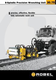
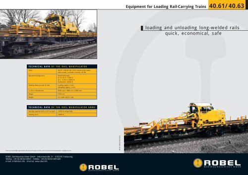
Equipment for Loading Rail-Carrying Trains 40.61/40.63<strong>loading</strong> <strong>and</strong> un<strong>loading</strong> <strong>long</strong>-<strong>welded</strong> <strong>rails</strong><strong>quick</strong>, <strong>economical</strong>, <strong>safe</strong>TECHNICAL DATA OF THE RAIL MANIPULATORDriveMaximum pulling forceLoading times per pair of <strong>rails</strong>L x W x H dimensionsGaugeWeightDEUTZ, KHD BF 4M 1012C diesel in-line motor,water-cooled, 4-cylinder, 4-stroke, 69 kWdiesel-hydrostaticat 10 km/h: 11800 Nat 0 - 4 km/h: 33000 Nmechanical: 32000 NLoading: approx. 4 min.Un<strong>loading</strong>: approx. 2 min.8500 mm x 3068 mm x 2880 mm2700 mm12 t (with driver’s cab)TECHNICAL DATA OF THE RAIL MANIPULATOR ARMSHoisting capacity with a 3.57 m reachSlewing force15000 N respectively10000 NDimensions <strong>and</strong> weights approximated. We reserve the right to modify in the course of technical development. Copyright secured.40.61/40.63/04.03/EROBEL Bahnbaumaschinen GmbH · Industriestraße 31 · D-83395 FreilassingTelefon: +49 (0) 8654/609-0 · Telefax: +49 (0) 8654/609-445e-mail: info@robel.info · Internet: www.robel.info
40.61/40.63 Equipment for Loading Rail-Carrying TrainsDRILLING GRINDING CUTTING TRANSPORTING TIGHTENING CONNECTING TAMPING MEASURING LIFTIPING PULLINGDRILLING For the <strong>quick</strong> <strong>and</strong> <strong>economical</strong> GRINDING <strong>loading</strong> CUTTING TRANSPORTING TIGHTENING CONNECTING TAMPING MEA<strong>and</strong> un<strong>loading</strong> of <strong>long</strong>-<strong>welded</strong> <strong>rails</strong>Rail train <strong>loading</strong> systemTING CLAMPING PULLING DRILLING GRINDING CUTTING TRANSPORTING TIGHTENING CONNECTING TASURING The rail LIFTING train loads <strong>and</strong> unloads CLAMPING <strong>long</strong>-<strong>welded</strong> <strong>rails</strong> on both PULLINGDRILLING straight <strong>and</strong>GRINDING CUTTING • TRANSPORTING Consists of 3 parts: TIGHTENING CONNcurved tracks <strong>quick</strong>ly <strong>and</strong> <strong>economical</strong>ly <strong>and</strong> transport them over <strong>long</strong>1) Double-sided chute unitTAMPING distances. MEASURING The equipment is mounted LIFTING on several connected CLAMPING goods PULLING DRILLING GRINDING2) Rail manipulatorCUTTING TRANSPORTING TIGwagons of suitable length. An independent gantry crane runs on an3) Double-sided transport unitCONNECTING auxiliary track laid TAMPING over the full length of the MEASURING rail carrying train. The <strong>long</strong><strong>welded</strong><strong>rails</strong> are stacked on the rail carrying train in three layers.Operated normally by a team of 4 operatorsLIFTING CLAMPING PULLINGDRILLING GRINDING CUTTING TRANSTIGHTENING CONNECTING TAMPING MEASURING LIFTING CLAMPING Possibility PULLING of <strong>loading</strong> <strong>and</strong> DRILLING un<strong>loading</strong> <strong>rails</strong> up to 500 GRINDING m in length CUTRANSPORTINGLoading of <strong>long</strong>-<strong>welded</strong> <strong>rails</strong>TIGHTENING CONNECTING TAMPING MEASURING LIFTING Hydrostatic traction brake, acts on all 4 wheelsCLAMPING PULLINGDRILLINWhen <strong>loading</strong> the <strong>long</strong>-<strong>welded</strong> <strong>rails</strong>, the rail-<strong>loading</strong> train travels a<strong>long</strong> theHydraulic multi-disc brake, acts diagonally on 2 wheelsCUTTING trackway TRANSPORTING to the point where the front ends of the TIGHTENING <strong>rails</strong> can be gripped by CONNECTING TAMPING MEASURING • Transport speeds up to 100 km/hLIFTING CLAMPING PULLINthe claws of the rail manipulator. The <strong>rails</strong> are then raised to the heightChute unitGRINDING of the last roller. CUTTING The locomotive shunts TRANSPORTING the rail carrying train under the TIGHTENING CONNECTING TAMPING MEASURING LIFTING CLAMPlifted <strong>rails</strong> <strong>and</strong> the <strong>rails</strong> are inserted into the grooves by the articulated• Is used to guide the <strong>rails</strong> on the transport unit during <strong>loading</strong> <strong>and</strong>LINGDRILLINGcranes <strong>and</strong> placed betweenGRINDINGthe guiding rollers ofCUTTINGthe chute wagon. WhileTRANSPORTING TIGHTENING CONNECTING un<strong>loading</strong> TAMPING MEASURING Lthe train is shunted under the <strong>rails</strong>, the gantry crane pulls on the <strong>rails</strong>CLAMPING PULLING DRILLING GRINDING CUTTING TRANSPORTING • Unit consists of two wagons; the structures are designedTIGHTENING CONNECTING TAMPINwith its own force to keep them straight. As soon as the ends of the <strong>rails</strong>symmetricallyRING LIFTING resting on the sleepers CLAMPING lose contact with the ground, PULLINGDRILLING the <strong>rails</strong> are hoistedhigher <strong>and</strong> higher by the rail manipulator until the final position isGRINDING CUTTING TRANSPORTING • The <strong>rails</strong> can be loaded or unloaded at the ends of the sleeper via theTIGHTENING CONNECtwo side chutes (rail grooves) or in the middle of the track via the twoPING MEASURING reached on the train. To load the LIFTING next <strong>rails</strong>, the rail CLAMPING manipulator movescentral chutes, as requiredPULLING DRILLING GRINDING CUTTING TRANSPORTING TIGHTEback to the starting position at the end of the train.• A rotating mechanism is fitted to one of the two chute wagons for theNECTING TAMPING MEASURING LIFTING CLAMPING PULLINGDRILLING gantry GRINDING crane CUTTING TRANSPORUn<strong>loading</strong> of <strong>long</strong>-<strong>welded</strong> <strong>rails</strong>TENING CONNECTING TAMPING MEASURING LIFTING CLAMPING PULLING Rail manipulatorDRILLING GRINDING CUTTINWhen un<strong>loading</strong>, each end of the pair of <strong>rails</strong> is gripped by the rail manipulator,lifted TIGHTENING up a short distance <strong>and</strong> inserted CONNECTING over the guiding rollers TAMPING MEASURING LIFTING • The rail manipulator is used to load <strong>and</strong> unload the <strong>rails</strong> on the railPORTING CLAMPING PULLINGDRILLING GRIinto the grooves. The rail manipulator then continue to grip the <strong>rails</strong> fromcarrying trainTING TRANSPORTING the rear <strong>and</strong> push them away from the TIGHTENING train until the ends of the <strong>rails</strong>CONNECTING TAMPING MEASURING • The workingLIFTINGhydraulics <strong>and</strong> theCLAMPINGhydrostatic traction mechanismPULLINGareDtouch the ground. These <strong>rails</strong> are fastened to the track by means ofpowered by a diesel engineGRINDING clamps <strong>and</strong> CUTTING short cables. The locomotive TRANSPORTING then pulls the train away from TIGHTENING CONNECTING TAMPING • The two arms MEASURING of the rail manipulator are operated LIFTING independently CLAMPofunder the anchored <strong>rails</strong>.each other by 2 operativesLINGDRILLING GRINDING CUTTING TRANSPORTING TIGHTENING CONNECTING TAMPING MEASURING LDuring un<strong>loading</strong>, the <strong>rails</strong> glide over tilted chutes fitted to the grooves.• Special rail claws, which can be <strong>quick</strong>ly changed over, are provided toThe cushioned ends of the chutes stop the ends of the <strong>rails</strong> hitting theensure that the <strong>rails</strong> are held securely <strong>and</strong> do not tilt during the liftingCLAMPING PULLING DRILLING GRINDING CUTTING TRANSPORTING TIGHTENING CONNECTING TAMPINsleepers.<strong>and</strong> pulling phaseRING LIFTING CLAMPING PULLINGDRILLING GRINDING CUTTING TRANSPORTING TIGHTENING CONNECRail manipulatorTwo-sided Transport UnitPING MEASURING The gantry crane travels the full LIFTING length of the rail CLAMPING train on the crane PULLING DRILLING GRINDING • The CUTTING <strong>rails</strong> lie on ball-bearing TRANSPORTING carrying rolls, which enable a simple TIGHTEtracks under its own momentum. The two arms of the rail manipulator,length compensation when driving through curved tracks <strong>and</strong> preventNECTING TAMPING MEASURING LIFTING CLAMPING PULLINGDRILLING GRINDING CUTTING TRANSPORwhich can be slewed up <strong>and</strong> down <strong>and</strong> sideways hydraulically, are mounteda derailmentTENINGon theCONNECTINGcrane wagon. Jointed <strong>and</strong> rotatingTAMPINGrail claws are fitted to theMEASURINGfront ofLIFTING CLAMPING PULLING • The ball-bearing carrying rolls also enable an easy moving of the <strong>rails</strong>DRILLING GRINDING CUTTINeach jib. The claws can be changed over to fit different types of <strong>rails</strong>.during <strong>loading</strong> <strong>and</strong> un<strong>loading</strong>PORTING TIGHTENING CONNECTING TAMPING MEASURING LIFTING • The running track for the rail manipulator runs the entire length of theCLAMPING PULLINGDRILLING GRItransport unit, including the chute unitTING TRANSPORTING TIGHTENING CONNECTING TAMPING MEASURING LIFTING CLAMPING PULLING DGRINDING CUTTING TRANSPORTING TIGHTENING CONNECTING TAMPING MEASURING LIFTING CLAMPLINGDRILLING GRINDING CUTTING TRANSPORTING TIGHTENING CONNECTING TAMPING MEASURING LCLAMPING PULLING DRILLING GRINDING CUTTING TRANSPORTING TIGHTENING CONNECTING TAMPIN