Clutch Coupling - Arten Freios e Embreagens Industriais
Clutch Coupling - Arten Freios e Embreagens Industriais
Clutch Coupling - Arten Freios e Embreagens Industriais
- No tags were found...

You also want an ePaper? Increase the reach of your titles
YUMPU automatically turns print PDFs into web optimized ePapers that Google loves.
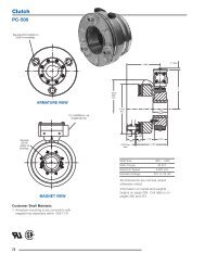
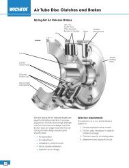
<strong>Clutch</strong> <strong>Coupling</strong>SFC-170 Flange MountedStd. Arm.AntibacklashArm..375.015 When New.086 (Std.).094 (Anti.)12.062ARMATURE VIEWFor Bore sizessee chart below..125 (Std.).109 (Anti.)For Bore & Keyway sizessee chart below. 2.4372.435Dia.1.718Max.Dia..625(Std.).843(Anti.).752.750Pilot Dia.Backing Plate Only45°#8-32UNC-3A1.812 Max. Sq..204/.187 dia. (4) holesequally spacedon 2.125 dia.Mounting holes arewithin .010 of trueposition relative to pilotdiameter..086 (Std.).094 (Anti.).515Max..015.1871.375 (Std.)1.359 (Anti.)Bore Dimensions.750RotorArmatureBore Dia. Keyway Bore Dia..251/.250 .062 x .031 .251/.250.313/.312 .062 x .031 .313/.312.376/.375 .093 x .046 .376/.375.160/.150.437Max.FIELD VIEWCustomer Shall Maintain:1. Squareness of field mounting face withrotor shaft within .003 T.I.R. measured at pilot diameter2. Concentricity of field mounting pilot diameterwith rotor mounting shaft within .003 T.I.R.3. Rotor and armature shafts in line within .003 T.I.R.Static TorqueMaximum Speed15 lb. in.5,000 rpmStandard Voltage D.C. 6, 24, 90All dimensions are nominal unlessotherwise noted.Information on inertia and weightsbegins on page 239. Coil data is onpages 250 and 251.94
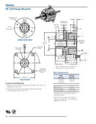
Drawing I-25756<strong>Clutch</strong> <strong>Coupling</strong>SFC-170 Flange Mounted421A1A-21A-31A-131BItem Description Part Number Qty.1AArmature and Hub1A-1 Armature Hub 11/4" Bore 5102-541-0025/16" Bore 5102-541-0033/8" Bore 5102-541-0041A-2 Armature 110-0111 11A-3 Release Spring 808-0019 11B Antibacklash Armature 11/4" Bore 5623-111-0085/16" Bore 5623-111-0093/8" Bore 5623-111-0102 Rotor 11/4" Bore 5603-751-0285/16" Bore 5603-751-0293/8" Bore 5603-751-0303 Mounting Accessory 5102-101-001 14 Field 16 Volt 5603-451-04724 Volt 5603-451-04990 Volt 5603-451-051How to Order:1. Specify Type of Armature Desired.2. Specify Bore Size for Item 1A-1 or 1B and Item 2.3. Specify Voltage for Item 4.4. See Controls Section.Example:SFC-170 <strong>Clutch</strong> per I-25756 - 90 VoltAntibacklash Armature1/4" Armature Hub Bore1/4" Rotor BoreThese units meet standards set forth in UL508 andare listed under guide card #NMTR2, file #59164.These units are CSA certified under file #LR11543.Refer to Service Manual P-200.95
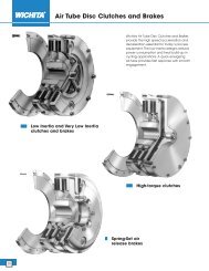
<strong>Clutch</strong> <strong>Coupling</strong>SFC-170 Bearing MountedStd. Arm.AntibacklashArm..375ARMATURE VIEWFor Bore sizessee chart below..086 (Std.).094 (Anti.).015 When New12.0621.87.500.125 (Std.).109 (Anti.).0931.718Max.Dia..625(Std.).843(Anti.).625Dia.For Bore sizessee chart below.1.0621.375.015.086 (Std.).094 (Anti.)1.0931.2031.562 Max..250Bore DimensionsRotorBore Dia.ArmatureBore Dia..251/.250 .251/.250.313/.312 .313/.312.376/.375 .376/.3751.750 Max. Dia.FIELD VIEWCustomer Shall Maintain:1. Alignment between rotor and armature shafts to be .003 T.I.R.Static TorqueMaximum Speed15 lb. in.5,000 rpmStandard Voltage D.C. 6, 24, 90All dimensions are nominal unlessotherwise noted.Information on inertia and weightsbegins on page 239. Coil data is onpages 250 and 251.96
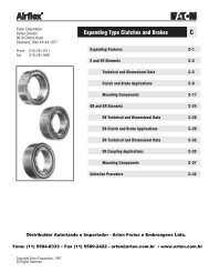
<strong>Clutch</strong> <strong>Coupling</strong>SFC-250 Flange MountedFor Bore & Keyway sizessee chart below.Std. Arm.AntibacklashArm..015 When New.343Max.1.125.468.062.171 (Std.).562 (Anti.).380/.370For Bore & Keywaysizes seechart below.ARMATURE VIEW24°12°.437 Max..437 Max.2.625Max.Dia.1.187(Std.)1.390(Anti.).687.1711.0631.061Pilot Dia.Backing PlateOnly2.625 Sq..171.546Max..015.7501.2508-32 UNC-3A.437Max.1.968 (Std.)1.984 (Anti.)3.500/3.498Pilot Dia.FIELD VIEWCustomer Shall Maintain:1. Squareness of field mounting face with rotor shaft within.003 T.I.R. measured at pilot diameter.2. Concentricity of field mounting pilot diameter with rotormounting shaft within .003 T.I.R.3. Rotor and armature shafts in line within .003 T.I.R.45°.204/.187 dia. (4) holes equally spaced on 3.125dia. Mounting holes are within .010 of true positionrelative to pilot diameter.Bore and Keyway DimensionsArmature Keyway Rotor KeywayBore Dia.Bore Dia..376/.375 .093 x .046*.438/.437 .376/.375 .093 x .046.501/.500 .125 x .062 *.438/.437 .125x .062*.563/.562 .501/.500.626/.625*.688/.687 .187 x .093.751/.750* Available on special order only.Static TorqueMaximum Speed70 lb. in.7,500 rpmStandard Voltage D.C. 6, 24, 90All dimensions are nominal unlessotherwise noted.Information on inertia and weightsbegins on page 239. Coil data is onpages 250 and 251.98
Drawing I-25522<strong>Clutch</strong> <strong>Coupling</strong>SFC-250 Flange Mounted3-1321A1A-21A-31A-141BItem Description Part Number Qty.1A Armature and Hub1A-1 Armature Hub 13/8" Bore 5103-541-0021/2" Bore 5103-541-0045/8" Bore 5103-541-0063/4" Bore 5103-541-0081A-2 Armature 5124-111-001 11A-3 Release Spring 5103-101-003 11B Antibacklash Armature 13/8" Bore 5365-111-0031/2" Bore 5365-111-0055/8" Bore 5365-111-0073/4" Bore 5365-111-0092 Rotor 13/8" Bore 5103-751-0081/2" Bore 5103-751-0103 Field 16 Volt 5103-451-00224 Volt 5103-451-00490 Volt 5103-451-007Item Description Part Number Qty.3-1 Terminal Accessory 5103-101-002 14 Mounting Accessory 5102-101-001 1How to Order:1. Specify Type of Armature Desired.2. Specify Bore Size for Item 1A-1 or 1-B and Item 2.3. Specify Voltage for Item 3.4. See Controls Section.Example:SFC-250 <strong>Clutch</strong> <strong>Coupling</strong> per I-25522 - 90 VoltStandard Armature1/2" Armature Hub Bore1/2" Rotor BoreThese units meet standards set forth in UL508 and arelisted under guide card #NMTR2, file #59164.These units are CSA certified under file #LR11543.Refer to Service Manual P-200.99
<strong>Clutch</strong> <strong>Coupling</strong>SFC-250 Bearing MountedFor Bore & Keyway sizessee chart below..343 Max.1.437Std. Arm.AntibacklashArm..015 (Std.).015 (Anti.)when new1.125.468.171 +.062 -0.062.687 (Std.).718 (Anti.)ARMATURE VIEW45°.437Max.24°.500 12°2.625Max.Dia.1.187(Std.)1.390(Anti.).609Dia..187 Dia..187 1.562 Rad..9371.750 Max..171 (Std.).187 (Anti.) .015 (Std.).687 .015 (Anti.)(Std.).7181.312(Anti.)2.156 (Std.)2.171 (Anti.).171Bore and Keyway DimensionsFor Bore & Keyway sizes seechart below.FIELD VIEWCustomer Shall Maintain:1. Armature shaft to be concentric with rotor shaftwithin .003 T.I.R.Armature Keyway Rotor KeywayBore Dia.Bore Dia..375/.376 .093 x .046 .376/.375 .093 x .046*.438/.437.501/.500 .125 x .062 *.438/.437 .125 x .062*.563/.562 .501/.500.626/.625*.688/.687 .187 x .093.751/.750* Available on special order only.Static TorqueMaximum Speed70 lb. in.7,500 rpmStandard Voltage D.C. 6, 24, 90All dimensions are nominal unlessotherwise noted.Information on inertia and weightsbegins on page 239. Coil data is onpages 250 and 251.100
Drawing I-255232(Shipped Assembled)<strong>Clutch</strong> <strong>Coupling</strong>SFC-250 Bearing Mounted2-52-4-12-42-22-1 2-22-31A1A-21A-31A-11BItem Description Part Number Qty.1A Armature and Hub1A-1 Armature Hub 13/8" Bore 5103-541-0021/2" Bore 5103-541-0045/8" Bore 5103-541-0063/4" Bore 5103-541-0081A-2 Armature 5124-111-001 11A-3 Release Spring 5103-101-003 11B Antibacklash Armature 13/8" Bore 5365-111-0031/2" Bore 5365-111-0055/8" Bore 5365-111-0073/4" Bore 5365-111-0092 Field and Rotor Assembly 16 Volt – 3/8" Bore 5103-452-00224 Volt – 3/8" Bore 5103-452-00490 Volt – 3/8" Bore 5103-452-0076 Volt – 1/2" Bore 5103-452-01624 Volt – 1/2" Bore 5103-452-01890 Volt – 1/2" Bore 5103-452-0212-1 Rotor 13/8" Bore 5103-751-0141/2" Bore 5103-751-016Item Description Part Number Qty.2-2 Retainer Ring 748-0371 22-3 Ball Bearing 166-0108 12-4 Field 16 Volt 5103-451-01824 Volt 5103-451-02090 Volt 5103-451-0232-4-1 Terminal Accessory 5103-101-002 12-5 Set Collar* 266-0005 1How to Order:1. Specify Type of Armature Desired.2. Specify Bore Size for Item 1A-1 or 1B and Item 2.3. Specify Voltage for Item 2.4. See Controls Section.Example:SFC-250 <strong>Clutch</strong> <strong>Coupling</strong> per I-25523 - 90 VoltStandard Armature1/2" Armature Hub Bore1/2" Rotor BoreThese units meet standards set forth in UL508 and arelisted under guide card #NMTR2, file #59164. These unitsare CSA certified under file #LR11543.*Used with 1/2" Bore only.Refer to Service Manual P-200.101
<strong>Clutch</strong> <strong>Coupling</strong>SFC-400 Flange MountedFor Bore & Keyway sizessee chart below.Std. Arm.AntibacklashArm.1.546.937ARMATURE VIEW.015 When NewRemovableplug in endsfor 1/2"conduit.3.750.328 Max..187 (Std.).218 (Anti.)3.562For Bore &Keywaysizes seechart below.4.6874.234Max.Dia.1.250(Std.)1.640(Anti.).875.6711.125.093.2501.8751.873Pilot Dia..187 (Std.).218 (Anti.)1/4-20UNC-3A4.250 Sq..328.828 1.312.0151.5001.502.328/2.359.192/.182.609 Max.5.6265.623Pilot Dia.FIELD VIEW*Mounting holes are within .010 of true position relative to pilotdiameter.45°.296/.280 dia. (4) holes equally spaced on 5.000 dia.*Customer Shall Maintain:1. Squareness of field mounting face with rotor shaft within.003 T.I.R. measured at pilot diameter.2. Concentricity of field mounting pilot diameter with rotormounting shaft within .003 T.I.R.®U LBore and Keyway DimensionsArmature Keyway Rotor KeywayBore Dia.Bore Dia..501/.500 .125 x .062 .501/.500 .125 x.062*.563/.562.626/.625 .626/.625*.688/.687 .187 x .093 .751/.750 .187 x .093.751/.750 .876/.875.876/.875 1.001/1.000*Available on special order onlyStatic TorqueMaximum Speed270 lb. in.4,500 rpmStandard Voltage D.C. 6, 24, 903. Rotor and armature shafts in line within .003 T.I.R. All dimensions are nominal unlessotherwise noted.Information on inertia and weightsbegins on page 239. Coil data is onpages 250 and 251.102
<strong>Clutch</strong> <strong>Coupling</strong>Drawing I-25697SFC-400 Flange Mounted41B3-11A1A-2231A-31A-15Item Description Part Number Qty.1A Armature and Hub1A-1 Armature Hub 11/2" Bore 5104-541-0025/8" Bore 5104-541-0043/4" Bore 5104-541-0067/8" Bore 5104-541-0071A-2 Armature 5125-111-001 11A-3 Release Spring 5104-101-003 11B Antibacklash Armature 11/2" Bore 5367-111-0035/8" Bore 5367-111-0053/4" Bore 5367-111-0077/8" Bore 5367-111-0082 Rotor 11/2" Bore 5104-751-0335/8" Bore 5104-751-0343/4" Bore 5104-751-0357/8" Bore 5104-751-0361" Bore 5104-751-0373 Field 16 Volt 5104-451-03224 Volt 5104-451-03390 Volt 5104-451-034Item Description Part Number Qty.3-1 Terminal Accessory 5103-101-002 14 Conduit Box 5200-101-010 15 Mounting Accessory 5104-101-002 1How to Order:1. Specify Type of Armature Desired.2. Specify Bore Size for Item 1A-1 or 1B and Item 2.3. Specify Voltage for Item 3.4. See Controls Section.Example:SFC-400 <strong>Clutch</strong> <strong>Coupling</strong> per I-25697 - 90 Volt3/4" Armature Hub Bore3/4" Rotor BoreThese units, when used in conjunction with the correctWarner Electric conduit box, meet standards set forth inUL508 and are listed under guide card #NMTR2, file#59164.These units are CSA certified under file #LR11543.Refer to Service Manual P-200.103
<strong>Clutch</strong> <strong>Coupling</strong>SFC-400 Bearing MountedFor Bore & Keyway sizessee chart below.1.5461.218Std. Arm.AntibacklashArm..015 (Std.).015 (Anti.) whennew.328 Max..062 (Std.)ARMATURE VIEW.875 (Std.).843(Anti.)3.56245°3.750Removableplug in endsfor 1/2"conduit.4.234Max.Dia.1.250(Std.)1.640(Anti.)1.375Dia..187.187.859.500For Bore & Keyway sizessee chart below.2.312FIELD VIEWCustomer Shall Maintain:1. Armature shaft to be concentric with rotorshaft within .003 T.I.R.4.687.187 (Std.).218 (Anti.).875 (Std.).843 (Anti.)Bore and Keyway DimensionsArmature Keyway Rotor KeywayBore Dia.Bore Dia..501/.500 .125 x .062 .501/.500 .125 x.062*.563/.562.626/.625 .626/.625*.688/.687 .187 x .093 .751/.750 .187 x .093.751/.750 .876/.875.876/.875 1.001/1.000* Available on special order only.Static Torque.015Maximum Speed1.281(Std.)1.8121.6252.640 (Std.)2.734 (Anti.)270 lb. in.4,500 rpmStandard Voltage D.C. 6, 24, 90All dimensions are nominal unlessotherwise noted.®U Lpages 250 and 251.Information on inertia and weightsbegins on page 239. Coil data is on.203 (Anti.).328 (Anti.)104
Drawing I-256981B3<strong>Clutch</strong> <strong>Coupling</strong>SFC-400 Bearing Mounted2(Shipped Assembled)2-4-12-22-42-12-31-A1A-21A-31A-1Item Description Part Number Qty.1A Armature and Hub1A-1 Armature Hub 11/2" Bore 5104-541-0025/8" Bore 5104-541-0043/4" Bore 5104-541-0067/8" Bore 5104-541-0071A-2 Armature 5125-111-001 11A-3 Release Spring 5104-101-003 11B Antibacklash Armature 11/2" Bore 5367-111-0035/8" Bore 5367-111-0053/4" Bore 5367-111-0077/8" Bore 5367-111-0082 Field and Rotor Assembly 16 Volt – 1/2" Bore 5104-452-05224 Volt – 1/2" Bore 5104-452-05390 Volt – 1/2" Bore 5104-452-0546 Volt – 5/8" Bore 5104-452-05524 Volt – 5/8" Bore 5104-452-05690 Volt – 5/8" Bore 5104-452-0576 Volt – 3/4" Bore 5104-452-05824 Volt – 3/4" Bore 5104-452-05990 Volt – 3/4" Bore 5104-452-0606 Volt – 7/8" Bore 5104-452-06124 Volt – 7/8" Bore 5104-452-06290 Volt – 7/8" Bore 5104-452-0636 Volt – 1" Bore 5104-452-06424 Volt – 1" Bore 5104-452-06590 Volt – 1" Bore 5104-452-066Item Description Part Number Qty.2-1 Rotor 11/2" Bore 5104-751-0435/8" Bore 5104-751-0443/4" Bore 5104-751-0457/8" Bore 5104-751-0461" Bore 5104-751-0472-2 Retainer Ring 748-0018 12-3 Ball Bearing 166-0150 12-4 Field 16 Volt 5104-451-03824 Volt 5104-451-03990 Volt 5104-451-0402-4-1 Terminal Accessory 5103-101-002 13 Conduit Box 5200-101-010 1How to Order:1. Specify Type of Armature Desired.2. Specify Bore Size for Item 1A-1 or 1-B and Item 2.3. Specify Voltage for Item 2.4. See Controls Section.Example:SFC-400 <strong>Clutch</strong> <strong>Coupling</strong> perI-25698 - 90 VoltAntibacklash Armature3/4" Armature Hub Bore3/4" Rotor BoreThese units meet standards set forth in UL508 and arelisted under guide card #NMTR2, file #59164. These unitsare CSA certified under file #LR11543.Refer to Service Manual P-200.105
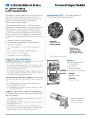
<strong>Clutch</strong> <strong>Coupling</strong>SFC-500 Bearing MountedNormal DutySee page 252 for details onBushings & keyways.1.5461.234.062 When New4.093HUB VIEW3.750Removable plug inends for 1/2"conduit.5 Dia.5.328Max Dia. 1.500.1871.750Dia.2.062Min.Flat45°.750.2185.2181.5931.3432.093.125 Max..2813.9373.156 Max.1062.781FIELD VIEWFor Bore & Keyway sizessee chart below.Customer Shall Maintain:1. Armature mounting shaft to be concentric with rotormounting shaft within .006 T.I.R.Bore & Keyway DimensionsRotorBore Dia.Armature Shaft .500 – 1.250Rotor Shaft .750 – 1.250Static TorqueMaximum SpeedKeyway.751/.750 .187 x .093.876/.875.9385/.93751.001/1.000 .250 x .1251.126/1.1251.251/1.25050 lb.ft.4,000 rpmStandard Voltage D.C. 6, 24, 90®U LAll dimensions are nominal unlessotherwise noted.Information on inertia and weightsbegins on page 239. Coil data is onpages 250 and 251.
Normal DutyDrawing I-25540<strong>Clutch</strong> <strong>Coupling</strong>SFC-500 Bearing Mounted325-2-1615-45-345-25-15(Shipped Assembled)Item Description Part Number Qty.1 Armature Hub 5300-541-004 12 Bushing* 11/2" to 1 1/4" Bore 180-0116 to 180-01283 Autogap Accessory 5200-101-009 34 Armature 5300-111-002 15 Field and Rotor Assembly 16 Volt – 3/4" Bore 5200-452-00224 Volt – 3/4" Bore 5200-452-00490 Volt – 3/4" Bore 5200-452-0056 Volt – 7/8" Bore 5200-452-00824 Volt – 7/8" Bore 5200-452-01090 Volt – 7/8" Bore 5200-452-01124 Volt – 15/16" Bore 5200-452-01690 Volt – 15/16" Bore 5200-452-0176 Volt – 1" Bore 5200-452-02024 Volt – 1" Bore 5200-452-02290 Volt – 1" Bore 5200-452-0236 Volt – 1-1/8" Bore 5200-452-02624 Volt – 1-1/8" Bore 5200-452-02890 Volt – 1-1/8" Bore 5200-452-0296 Volt – 1-1/4" Bore 5200-452-03224 Volt – 1-1/4" Bore 5200-452-03490 Volt – 1-1/4" Bore 5200-452-0355-1 Rotor 13/4" Bore 5200-751-0027/8" Bore 5200-751-00315/16" Bore 5200-751-004Item Description Part Number Qty.1" Bore 5200-751-0051-1/8" Bore 5200-751-0061-1/4" Bore 5200-751-0075-2 Field & Bearing Assembly 16 Volt 5200-451-02424 Volt 5200-451-02690 Volt 5200-451-0275-2-1 Terminal Accessory 5311-101-001 15-3 Ball Bearing 166-0110 15-4 Retainer Ring 748-0002 16 Conduit Box 5200-101-010 1How to Order:1. Specify Bore Size for Item 2 and Item 5.2. Specify Voltage for Item 5.3. See Controls Section.Example:SFC-500 <strong>Clutch</strong> <strong>Coupling</strong> per I-25540 - 90 Volt3/4" BoresThese units, when used in conjunction with the correctWarner Electric conduit box, meet the standards set ofUL508 and are listed under guide card #NMTR2, file#59164.These units are CSA certified under file #LR11543*See page 252 for specific part numbers.Refer to Service Manual P-202.107
<strong>Clutch</strong> <strong>Coupling</strong>SFC-500 Bearing MountedHeavy Duty1.5461.234For Bore & Keywaysizes see chartbelow.4.09345°ARMATURE VIEW3.750Removable plug inends for 1/2"conduit.5.328Max. 5.125Dia. Dia..171Max.1.203.1871.75Dia.2.062Min.Flat.062 When New.375.125.750.2185.2181.3431.5932.0933.218.281Bore & Keyway Dimensions3.156 Max. 2.781Bore Dia.Keyway.751/.750 .187 x .093.876/.875.9385/.93751.001/1.000 .250 x .1251.126/1.1251.251/1.250FIELD VIEWFor Bore & Keyway sizessee chart below.Customer Shall Maintain:1. Angular alignment of shafts within 1/2 degree.2. Armature mounting shaft to be concentric with rotormounting shaft within .006 T.I.R.Armature Shaft .750 – 1.250Rotor Shaft .750 – 1.250Static TorqueMaximum Speed50 lb.ft.4,000 rpmStandard Voltage D.C. 6, 24, 90®U LAll dimensions are nominal unlessotherwise noted.Information on inertia and weightsbegins on page 239. Coil data is onpages 250 and 251.108
Heavy DutyDrawing I-25541<strong>Clutch</strong> <strong>Coupling</strong>SFC-500 Bearing Mounted2B(Shipped Assembled)2B-12B-42B-33-2-142B-52B-23-413-33-23-13(Shipped Assembled)Item Description Part Number Qty.1 Armature Hub Assembly 13/4" Bore 5200-541-0027/8" Bore 5200-541-00315/16" Bore 5200-541-0041" Bore 5200-541-0051-1/8" Bore 5200-541-0061-1/4" Bore 5200-541-0072B Armature Assembly w/Autogap 5230-111-002 12B-1 Armature 5230-111-001 12B-2 Retainer Ring 748-0355 12B-3 Autogap Spring 808-0412 12B-4 Retainer Plate 748-0364 12B-5 Screw 797-0028 33 Field and Rotor Assembly 16 Volt – 3/4" Bore 5200-452-00224 Volt – 3/4" Bore 5200-452-00490 Volt – 3/4" Bore 5200-452-0056 Volt – 7/8" Bore 5200-452-00824 Volt – 7/8" Bore 5200-452-01090 Volt – 7/8" Bore 5200-452-01124 Volt – 15/16" Bore 5200-452-01690 Volt – 15/16" Bore 5200-452-0176 Volt – 1" Bore 5200-452-02024 Volt – 1" Bore 5200-452-02290 Volt – 1" Bore 5200-452-0236 Volt – 1-1/8" Bore 5200-452-02624 Volt – 1-1/8" Bore 5200-452-02890 Volt – 1-1/8" Bore 5200-452-0296 Volt – 1-1/4" Bore 5200-452-03224 Volt – 1-1/4" Bore 5200-452-03490 Volt – 1-1/4" Bore 5200-452-035Item Description Part Number Qty.3-1 Rotor 13/4" Bore 5200-751-0027/8" Bore 5200-751-00315/16" Bore 5200-751-0041" Bore 5200-751-0051-1/8" Bore 5200-751-0061-1/4" Bore 5200-751-0073-2 Field & Bearing Assembly 16 Volt 5200-451-02424 Volt 5200-451-02690 Volt 5200-451-0273-2-1 Terminal Accessory 5311-101-001 13-3 Ball Bearing 166-0110 13-4 Retainer Ring 748-0002 14 Conduit Box 5200-101-010 1How to Order:1. Specify Bore Size for Item 1 and Item 3.2. Specify Voltage for Item 3.3. See Controls Section.Example:SFC-500 <strong>Clutch</strong> <strong>Coupling</strong> per I-25541- 90 Volt3/4" Armature Hub Bore7/8" Rotor BoreThese units, when used in conjunction with the correctWarner Electric conduit box, meet standards set forth inUL508 and are listed under guide card #NMTR2, file#59164.These units are CSA certified under file #LR11543Refer to Service Manual P-202.109
<strong>Clutch</strong> <strong>Coupling</strong>SFC-650 Flange MountedSee page 252 fordetails on Bushings.1.546.937HUB VIEW.062When New3.750Removable plug inends for 1/2" conduit.ReversibleHub5/16-18UNC-3A4.6253.58/.338 dia. (4)holes equally spacedon 3.688 dia.*5.7506.687Max.Dia.6.500Dia.11.6562.822/2.820 Dia.4.375 Dia.6.50045°8.0007.998.062 Max.Min. Running Clearance3.5001.812Max..578Customer Shall Maintain:1. Concentricity of field mounting pilot diameter with rotormounting shaft within .006 T.I.R.2. Squareness of field mounting face with shaft within .006T.I.R. measured at field mounting bolt circle.3. Rotor mounting pilot diameter must be concentric with shaftwithin .006 T.I.R.4. Armature mounting shaft to be concentric with rotormounting shaft within .006 T.I.R.110FIELD VIEW(Inside & Outside Mounted)3.58/.338 dia. (4) holes equallyspaced on 7.250 dia.** Mounting holes are within .010 of trueposition relative to pilot diameter.Armature Shaft .500 – 1.625Rotor Shaft .500 – 1.625Static TorqueMaximum Speed95 lb.ft.3,600 rpmStandard Voltage D.C. 6, 24, 90All dimensions are nominal unlessotherwise noted.®U LInformation on inertia and weightsbegins on page 239. Coil data is onpages 250 and 251.
Drawing I-25728<strong>Clutch</strong> <strong>Coupling</strong>SFC-650 Flange Mounted641957A7A-19387B-1227B8Item Description Part Number Qty.1 Autogap Accessory 5181-101-010 42 Bushing* 21/2" to 1-5/8" Bore 180-0326 to 180-0344 13 Armature Hub 5207-541-002 14 Armature 5281-111-002 15 Rotor 5281-751-001 16 Rotor Hub &Mounting Accessory 5207-101-005 17A Field - Inside Mounted 16 Volt 5207-451-00924 Volt 5207-451-01290 Volt 5207-451-0117A-1 Terminal Accessory 5311-101-001 17B Field - Outside Mounted 16 Volt 5207-451-00324 Volt 5207-451-00690 Volt 5207-451-0057B-1 Terminal Accessory 5311-101-001 1Item Description Part Number Qty.8 Mounting Accessory 5321-101-002 19 Conduit Box 5200-101-010 1How to Order:1. Specify Bore Size for Item 2 (both shafts).2. Specify Voltage for Item 7.3. Specify Inside or Outside Mounted for Item 7.4. See Controls Section.Example:SFC-650 <strong>Clutch</strong> <strong>Coupling</strong>Flange Mounted per I-25728 - 90 Volt1" BoreThese units, when used in conjunction with the correctWarner Electric conduit box, meet the standards of UL508and are listed under guide card #NMTR, file #59164.These units are CSA certified under file #LR11543.*See page 252 for specific part numbers.Refer to Service Manual P-202.111
<strong>Clutch</strong> <strong>Coupling</strong>SFC-650 Bearing MountedSee page 252 fordetails on Bushings.1.546.937.062When NewReversible Hub4.625HUB VIEW3.750Removable plug inends for 1/2" conduit.6.687Max.Dia.6.500Dia.1.001.7501.2506.359 Dia..15645°ReverseMounting5.750.312.4211/4-20 UNC-2A.7651.7813.5003.750.062Min. RunningClearance3.625FIELD VIEWCustomer Shall Maintain:1. Armature mounting shaft to be concentric with rotormounting shaft within .006 T.I.R.See page 252 for detailson Bushings.Armature Shaft .500 – 1.625Rotor Shaft .500 – 1.500Static TorqueMaximum Speed95 lb.ft.3,600 rpmStandard Voltage D.C. 6, 24, 90All dimensions are nominal unlessotherwise noted.®U LInformation on inertia and weightsbegins on page 239. Coil data is onpages 250 and 251.112
Drawing I-257294<strong>Clutch</strong> <strong>Coupling</strong>SFC-650 Bearing Mounted185-735-4-15-55-425-25-35-65-1675Item Description Part Number Qty.1 Autogap Accessory 5181-101-010 42 Bushing* 11/2" to 1-5/8" Bore 180-0326 to 180-03443 Armature Hub 5207-541-002 14 Armature 5281-111-002 15 Field and Rotor Assembly 16 Volt 5207-452-00224 Volt 5207-452-00590 Volt 5207-452-0045-1 Rotor Assembly 5281-751-001 15-2 Rotor Hub 540-0614 15-3 Reverse Mounting Accessory 5201-101-005 15-4 Field Assembly 16 Volt 5281-451-00224 Volt 5281-451-00490 Volt 5281-451-0055-4-1 Terminal Accessory 5311-101-001 15-5 Ball Bearing 166-0104 15-6 Retainer Ring - Exterior 748-0004 1Item Description Part Number Qty.5-7 Retainer Ring - Interior 748-0104 16 Bushing* 11/2" to 1-1/2" Bore 180-0002 to180-0018†7 Torque Arm Accessory 5207-101-003 18 Conduit Box 5200-101-010 1How to Order:1. Specify Bore Size of Item 2 and Item 6.2. Specify Voltage for Item 5.3. See Controls Section.Example:SFC-650 <strong>Clutch</strong> <strong>Coupling</strong>,Bearing Mounted per I-25729 - 90 Volt, 1" BoreThese units, when used in conjunction with the correctWarner Electric conduit box, meet the standards of UL508and are listed under guide card #NMTR, file #59164.These units are CSA certified under file #LR11543*See page 252 for specific part numbers.Refer to Service Manual P-202.†Optional – not included in price.113
<strong>Clutch</strong> <strong>Coupling</strong>SFC-825 Flange MountedSee page 252 fordetails on Bushings.1.546.9215.656ARMATURE VIEW3.750 Max.Removable plug in endsfor 1/2" conduit.8.656Max.Dia.4.250Dia.2.500Dia.1.2501.00.1561.765.6872.2532.251PilotDia.6.8123.503/3.501Pilot Dia..2815/16-18UNC-3A.358/.338 dia. (6)holes equallyspaced on 4.250dia. *.0621.312.5314.406 Max..602/.586.562 Max..358/.338 dia.(4) holesequally spacedon 8.875 dia. * 9.749/9.747Pilot Dia..350/.341 dia. (6)holes equallyspaced on 2.875dia. **FIELD VIEW(Inside & Outside Mounted)Customer Shall Maintain:1. Concentricity of field mounting pilot diameter with rotormounting shaft within .006 T.I.R.2. Squareness of field mounting face with rotor shaft within.006 T.I.R. measured at field mounting bolt circle.3. Rotor mounting shaft concentric with armature mountingshaft within .006 T.I.R.4. Angular alignment of shafts wtihin 1/2 degree.* Mounting holes are within .010 of trueposition relative to pilot diameter.** Mounting holes are within .008 of trueposition relative to pilot diameter.Armature Shaft .500 – 1.500Rotor Shaft .500 – 1.250Static TorqueMaximum Speed125 lb. ft.4,000 rpmStandard Voltage D.C. 6, 24, 90All dimensions are nominal unlessotherwise noted.®U LInformation on inertia and weightsbegins on page 239. Coil data is onpages 250 and 251.Note: The two mating shafts on whichthe clutch is mounted must be mountedrigidly to prevent flexing duringengagement. Any flexing will causevibration and rapid clutchwear. Thedrive motor should not be mounted onthe reducer "scoop" mount or otherflexible mounts.114
Drawing I-25564<strong>Clutch</strong> <strong>Coupling</strong>SFC-825 Flange Mounted4(Shipped Assembled)4-64-49A1111234-14-24-34-510A9B8167510BItem Description Part Number Qty.1 Bushing* 11/2" to 1-1/2" Bore 180-0002 to 180-00182 Retainer Ring 748-0006 13 Splined Hub 540-0057 14 Armature & Splined Adapter 5201-111-001 14-1 Capscrew 797-0341 34-2 Splined Adapter 104-0008 14-3 Autogap Accessory 5321-101-006 14-4 Spacer 748-0333 34-5 Armature 5321-111-022 14-6 Locknut 661-0004 35 Mounting Accessory 5201-101-007 16 Rotor 1Standard Friction Material 5201-751-003†Optional LK Facing 5201-751-0077 Bushing* 11/2" to 1-1/4" Bore 180-0101 to 180-00138 Rotor Hub 540-0013 19A Field - Inside Mounted 16 Volt 5201-451-00624 Volt 5201-451-00890 Volt 5201-451-010Item Description Part Number Qty.9B Field - Outside Mounted 16 Volt 5201-451-01424 Volt 5201-451-01690 Volt 5201-451-01810A Mounting Accessory - I.M. 5321-101-001 110B Mounting Accessory - O.M. 5321-101-002 111 Conduit Box 5200-101-012 1How to Order:1. Specify Bore Size for Item 1.2. Specify Bore Size for Item 7.3. Specify Voltage for Item 9A or 9B.4. Specify Inside Mounted for Items 9A and 10A orOutside Mounted for Items 9B and 10B.5. See Controls Section.Example:SFC-825 <strong>Clutch</strong> <strong>Coupling</strong> per I-25564 - 90 Volt, InsideMounted, 1" Bore (Item 1), 1" Bore (Item 7)These units, when used in conjunction with the correctWarner Electric conduit box, meet standards of UL508and are listed under guide card #NMTR, file #59164.These units are CSA certified under file #LR11543.*See page 252 for specific part numbers.Refer to Service Manual P-207.†Optional LK facing available. For more information,see page 232.115
<strong>Clutch</strong> <strong>Coupling</strong>SFC-825 Bearing MountedSee page 252 fordetails on Bushings.1.546.9845.656ARMATURE VIEW4.250Dia.1.2502.500Dia.1.7651.2501.6568.656Max.Dia.3.750Removable plug in endsfor 1/2" conduit.45°.156.875.062.3436.812.5621.296.187Reverse Mounting4.468 Max.4.562 Max..350/.3425.000See page 252 for detailson Bushings.Armature Shaft .500 – 1.500Rotor Shaft .500 – 1.500Static TorqueMaximum Speed150 lb. ft.3,600 rpmStandard Voltage D.C. 6, 24, 90All dimensions are nominal unlessotherwise noted.FIELD VIEWCustomer Shall Maintain:1. Armature mounting shaft concentric with field and rotormounting shaft within .006 T.I.R.2. Angular alignment of shafts within 1/2 degree.®U LInformation on inertia and weightsbegins on page 239. Coil data is onpages 250 and 251.116
Drawing I-25574<strong>Clutch</strong> <strong>Coupling</strong>SFC-825 Bearing Mounted4(Shipped Assembled)4-24-34-44-665-45-524-14-55-1 5-25-3135(Shipped Assembled)1Item Description Part Number Qty.1 Bushing* 21/2" to 1-1/2" Bore 180-0002 to 180-00182 Retainer Ring 748-0006 13 Splined Hub 540-0057 14 Armature & Splined Adapter 5201-111-001 14-1 Capscrew 797-0341 34-2 Splined Adapter 104-0008 14-3 Autogap Accessory 5321-101-006 14-4 Spacer 748-0333 34-5 Armature 5321-111-022 14-6 Locknut 661-0004 35 Field & Rotor Assembly 16 Volt 5201-452-00224 Volt 5201-452-00490 Volt 5201-452-0065-1 Rotor 1Standard Friction Material 5201-751-0085-2 Mounting Accessory 5201-101-005 15-3 Field 16 Volt 5201-451-05424 Volt 5201-451-05690 Volt 5201-451-057Item Description Part Number Qty.5-4 Retainer Ring 748-0111 15-5 Retainer Ring 748-0016 16 Conduit Box 5200-101-012 1How to Order:1. Specify Bore Size for Item 1 (both shafts).2. Specify Voltage for Item 5.3. See Controls Section.Example:SFC-825 <strong>Clutch</strong> <strong>Coupling</strong> per I-25574 - 90 Volt, 1" BoreThese units, when used in conjunction with the correctWarner Electric conduit box, meet the standards of UL508and are listed under guide card #NMTR, file #59164.These units are CSA certified under file #LR11543.*See page 252 for specific part numbers.Refer to Service Manual P-207.117
<strong>Clutch</strong> <strong>Coupling</strong>SFC-1000 Flange MountedSee page 252 for details onBushings.1.546.9216.531ARMATURE VIEW3.750 Max.Removable plug in ends for1/2" conduit.10.328Max.Dia.6.000Dia.4.093Dia.2.5001.250.2342.687.2504.1284.126PilotDia..0937.6875.378/5.376 PilotDia.5/16-18UNC-3A.358/.338 dia. (6)holes equallyspaced on 6.125dia. *.0621.375.5005.359 Max..570/.554.562 Max..358/.338 dia.(8) holesequally spacedon 10.625 dia.*Customer Shall Maintain:1. Concentricity of field mounting pilot diameter with rotormounting shaft within .006 T.I.R.2. Squareness of field mounting face with rotor shaft within.006 T.I.R. measured at field mounting bolt circle.3. Rotor mounting shaft concentric with armature mountingshaft within .006 T.I.R.4. Angular alignment of shafts wtihin 1/2 degree.118.350/.341 dia. (6) holesequally spaced on 4.875dia. **FIELD VIEW(Inside & Outside Mounted)11.500/11.498Pilot Dia.* Mounting holes are within .010 of trueposition relative to pilot diameter.** Mounting holes are within .008 of trueposition relative to pilot diameter.Armature Shaft .750 – 2.687Rotor Shaft .500 – 2.000Static TorqueMaximum Speed240 lb. ft.3,600 rpmStandard Voltage D.C. 6, 24, 90All dimensions are nominal unlessotherwise noted.®U LInformation on inertia and weightsbegins on page 239. Coil data is onpages 250 and 251.Note: The two mating shafts on whichthe clutch is mounted must be mountedrigidly to prevent flexing duringengagement. Any flexing will causevibration and rapid clutchwear. Thedrive motor should not be mounted onthe reducer "scoop" mount or otherflexible mounts.
Drawing I-25584<strong>Clutch</strong> <strong>Coupling</strong>SFC-1000 Flange Mounted4(Shipped Assembled)4-64-49A1111234-14-24-34-510A9B8167510BItem Description Part Number Qty.1 Bushing* 13/4" to 2-11/16" Bore 180-0026 to 180-00572 Retainer Ring 748-0007 13 Splined Hub 540-0062 14 Armature & Splined Adapter 5202-111-001 14-1 Capscrew 797-0341 34-2 Splined Adapter 104-0009 14-3 Autogap Accessory 5322-101-004 14-4 Spacer 748-0333 34-5 Armature 5322-111-036 14-6 Locknut 661-0004 35 Mounting Accessory 5201-101-007 16 Rotor 1Standard Friction Material 5202-751-003†Optional LK Facing 5202-751-0077 Bushing* 11/2" to 2" Bore 180-0155 to 180-01798 Rotor Hub 540-0315 19A Field - Inside Mounted 16 Volt 5202-451-00424 Volt 5202-451-00690 Volt 5202-451-007Item Description Part Number Qty.9B Field - Outside Mounted 16 Volt 5202-451-01124 Volt 5202-451-01390 Volt 5202-451-01410A Mounting Accessory - I.M. 5321-101-001 110B Mounting Accessory - O.M. 5321-101-002 211 Conduit Box 5200-101-012 1How to Order:1. Specify Bore Size for Item 1.2. Specify Bore Size for Item 7.3. Specify Voltage for Item 9A or 9B.4. Specify Inside Mounted for Items 9A and 10Aor Outside Mounted for Items 9B and 10B.5. See Controls Section.Example:SFC-1000 <strong>Clutch</strong> <strong>Coupling</strong> per I-25584 - 90 Volt, InsideMounted, 1-1/4" Bore (Item 1), 1-1/2" Bore (Item 7)These units, when used in conjunction with the correctWarner Electric conduit box, meet standards of UL508and are listed under guide card #NMTR, file #59164.These units are CSA certified under file #LR11543.*See page 252 for specific part numbers.Refer to Service Manual P-207.†Optional LK facing available. For more information, seepage 232.119
<strong>Clutch</strong> <strong>Coupling</strong>SFC-1000 Bearing MountedSee page 252 for detailson Bushings.1.5461.421ARMATURE VIEW6.53145°.8753.750Removable plug in endsfor 1/2" conduit.10.328Max.Dia.6.000Dia.4.093Dia..2342.5002.6872.0621.2502.562Dia..3437.687.0626.125.5621.375.187.437.350/.3425.890 Max.FIELD VIEWCustomer Shall Maintain:1. Armature mounting shaft concentric with field and rotormounting shaft within .006 T.I.R.2. Angular alignment of shafts within 1/2 degree.See page 252 for details onBushings.Armature Shaft .750 – 2.687Rotor Shaft .500 – 2.000Static TorqueMaximum Speed240 lb. ft.2,500 rpmStandard Voltage D.C. 6, 24, 90All dimensions are nominal unlessotherwise noted.®U LInformation on inertia and weightsbegins on page 239. Coil data is onpages 250 and 251.120
<strong>Clutch</strong> <strong>Coupling</strong>SFC-1000 Bearing MountedDrawing I-255984(Shipped Assembled)4-664-24-34-475-35-45-53 4-15-2124-55-15-85-95-105-65-75(Shipped Assembled)Item Description Part Number Qty.1 Bushing* 13/4" to 2-11/16" Bore 180-0026 to 180-00572 Retainer Ring 748-0007 13 Splined Hub 540-0062 14 Armature & Splined Adapter 5202-111-001 14-1 Capscrew 797-0341 34-2 Splined Adapter 104-0009 14-3 Autogap Accessory 5322-101-004 14-4 Spacer 748-0333 34-5 Armature 5322-111-036 14-6 Locknut 661-0004 35 Field & Rotor Assembly 16 Volt 5202-452-01224 Volt 5202-452-01490 Volt 5202-452-0155-1 Rotor 1Standard Friction Material 5202-751-003†Optional LK Facing 5202-751-0075-2 Field & Bearing Assembly 16 Volt 5202-451-04024 Volt 5202-451-04290 Volt 5202-451-0435-3 Retainer Ring 748-0116 15-4 Ball Bearing 166-1046 1Item Description Part Number Qty.5-5 Retainer Ring 748-0582 15-6 Rotor Hub 540-1300 15-7 Buttonhead Capscrew 797-1261 65-8 Ring Adapter 748-1047 15-9 Lockwasher 950-0359 65-10 Socket Head Capscrew 797-0422 66 Bushing* 11/2" to 2" Bore 180-0155 to 180-01797 Conduit Box 5200-101-012 1How to Order:1. Specify Bore Size for Items 1 and 6.2. Specify Voltage for Item 5.3. See Controls Section.Example:SFC-1000 <strong>Clutch</strong> <strong>Coupling</strong> per I-25598 - 90 Volt, 1" BoreThese units, when used in conjunction with the correctWarner Electric conduit box, meet the standards of UL508and are listed under guide card #NMTR, file #59164.These units are CSA certified under file #LR11543.*See page 252 for specific part numbers.Refer to Service Manual P-207.†Optional LK facing available. For more information, seepage 232.121
<strong>Clutch</strong> <strong>Coupling</strong>SFC-1225 Flange MountedSee page252 for detailson bushings.1.546.921ARMATURE VIEW3.750Removable plug in endsfor 1/2" conduit.7.5318.687 Max..358/.338 dia. (6) holes equallyspaced on 7.250 dia.*6.378/6.376 Pilot Dia.12.703Max.Dia. 12.625Dia. 4.093Dia.7.062Dia.2.5002.6871.750.562.3125.4385.436PilotDia..350/.341 dia. (8) holesequally spaced on 6.062dia.**.234.281.0625/16-18 UNC-3A13.875/13.871 Pilot Dia..5625.890 Max.1.562.758.742FIELD VIEW(Inside & Outside Mounted).358/.338 dia. (8) holes equallyspaced on 13.000 dia.** Mounting holes are within .010 of trueposition relative to pilot diameter.** Mounting holes are within .008 of trueposition relative to pilot diameter.Customer Shall Maintain:1. Concentricity of field mounting pilot diameter with rotormounting shaft within .006 T.I.R.2. Squareness of field mounting face with rotor mounting shaftwithin .006 T.I.R. measured at field mounting bolt circle.3. Rotor mounting shaft concentric with armature mountingshaft within .006 T.I.R.4. Angular alignment of shafts within 1/2 degree.When Hub is Furnished by Customer:Rotor mounting pilot diameter must be concentric with rotormounting shaft within .006 T.I.R.Armature Shaft .750 – 2.687Rotor Shaft .500 – 2.500Static TorqueMaximum Speed465 lb. ft.3,000 rpmStandard Voltage D.C. 6, 24, 90All dimensions are nominal unlessotherwise noted.®U LInformation on inertia and weightsbegins on page 239. Coil data is onpages 250 and 251.122
<strong>Clutch</strong> <strong>Coupling</strong>SFC-1225 Flange MountedDrawing I-256044(Shipped Assembled)4-54-64-34-49A114-2234-110A111679B810B5Item Description Part Number Qty.1 Bushing* 13/4" to 2-11/16" Bore 180-0026 to 180-00572 Retainer Ring 748-0005 13 Splined Hub 540-0064 14 Armature & Splined Adapter 5203-111-001 14-1 Locknut 661-0004 44-2 Splined Adapter 104-0010 14-3 Autogap Accessory 5323-101-002 14-4 Spacer 266-0004 44-5 Armature 5323-111-034 14-6 Screw 797-0356 45 Mounting Accessory 5321-101-002 26 Rotor 1Standard Friction Material 5203-751-001†Optional LK Facing 5203-751-0047 Bushing* 11/2" to 2-1/2" Bore 180-0185 to 180-02178 Rotor Hub 540-0318 19A Field - Inside Mounted 16 Volt 5203-451-00224 Volt 5203-451-00690 Volt 5203-451-0059B Field - Outside Mounted 16 Volt 5203-451-01024 Volt 5203-451-01390 Volt 5203-451-011Item Description Part Number Qty.10A Mounting Accessory - I.M. 5321-101-001 110B Mounting Accessory - O.M. 5321-101-002 211 Conduit Box 5200-101-012 1How to Order:1. Specify Bore Size for Item 1.2. Specify Bore Size for Item 7.3. Specify Voltage for Item 9A or 9B.4. Specify Inside or Outside Mounted for Item 5.5. Specify Inside Mounted for Items 9A and 10A orOutside Mounted for Items 9B and 10B.6. See Controls Section.Example:SFC-1225 <strong>Clutch</strong> <strong>Coupling</strong> perI-25604 - 90 Volt, Inside Mounted,1-1/2" Bore (Item 1), 1-3/4" Bore (Item 7).These units, when used in conjunction with the correctWarner Electric conduit box, meet the standards of UL508and are listed under guide card #NMTR, file #59164.These units are CSA certified under file #LR11543.*See page 252 for specific part numbers.Refer to Service Manual P-207.†Optional LK facing available. For more information, seepage 232.123
<strong>Clutch</strong> <strong>Coupling</strong>SFC-1225 Bearing MountedSee page 252 fordetails on bushings.1.5461.500ARMATURE VIEW7.531.87545°3.750Removable plug in endsfor 1/2" conduit.12.703Max.Dia.12.625Dia.7.062Dia. 4.093Dia.2.5002.6871.7502.6253.125Dia..3438.687 Max..234.350/.3427.000.062.5626.421 Max.1.562.187.515FIELD VIEWCustomer Shall Maintain:1. Armature mounting shaft concentric with field and rotormounting shaft within .006 T.I.R.2. Angular alignment of shafts within 1/2 degree.See page 252 fordetails on bushings.Armature Shaft .750 – 2.687Rotor Shaft .500 – 2.500Static TorqueMaximum Speed465 lb. ft.2,200 rpmStandard Voltage D.C. 6, 24, 90All dimensions are nominal unlessotherwise noted.®U LInformation on inertia and weightsbegins on page 239. Coil data is onpages 250 and 251.124
<strong>Clutch</strong> <strong>Coupling</strong>Drawing I-256234(Shipped Assembled)4-1SFC-1225 Bearing Mounted4-44-64-24-375-35-45-5234-55-215-75-15-105-65-965-85(Shipped Assembled)Item Description Part Number Qty.1 Bushing* 13/4" to 2-11/16" Bore 180-0026 to 180-00572 Retainer Ring 748-0005 13 Splined Hub 540-0064 14 Armature & Splined Adapter 5203-111-001 14-1 Capscrew 797-0356 44-2 Splined Adapter 104-0010 14-3 Autogap Accessory 5323-101-002 14-4 Spacer 266-0004 44-5 Armature 5323-111-034 14-6 Locknut 661-0005 45 Field & Rotor Assembly 16 Volt 5203-452-00924 Volt 5203-452-01190 Volt 5203-452-0125-1 Rotor 1Standard Friction Material 5203-751-001†Optional LK Facing 5203-751-0045-2 Field 16 Volt 5203-451-03424 Volt 5203-451-03690 Volt 5203-451-0375-3 Retainer Ring 748-0119 15-4 Ball Bearing 166-1047 1Item Description Part Number Qty.5-5 Retainer Ring 748-0011 15-6 Rotor Hub 540-1304 15-7 Ring Adapter 748-0591 15-8 Buttonhead Capscrew 797-1261 65-9 Lockwasher 950-0359 65-10 Sockethead Capscrew 797-0424 66 Bushing* 11/2" to 2-1/2" Bore 180-0185 to 180-02177 Conduit Box 5200-101-012 1How to Order:1. Specify Bore Size for Item 1.2. Specify Bore Size for Item 6.3. Specify Voltage for Item 5.4. See Controls Section.Example:SFC-1225 <strong>Clutch</strong> <strong>Coupling</strong> per I-25623 - 90 Volt, 1" BoreThese units, when used in conjunction with the correctWarner Electric conduit box, meet the standards of UL508and are listed under guide card #NMTR, file #59164.These units are CSA certified under file #LR11543.*See page 252 for specific part numbers.Refer to Service Manual P-207.†Optional LK facing available. For more information, seepage 232.125
<strong>Clutch</strong> <strong>Coupling</strong>SFC-1525 Flange MountedSee page 252 fordetails on bushings.1.546.921ARMATURE VIEW3.750Removable plug in ends for 1/2" conduit.9.18710.343 Max..358/.338 dia. (12) holes equallyspaced on 9.750 dia.*9.002/9.000 Pilot Dia.15.671Max.Dia. 15.578Dia. 4.093Dia.8.750Dia.2.5002.687.5622 .2187.8787.876PilotDia..350/.341 dia. (8) holesequally spaced on 8.500 dia.**.234.062.4375/16-18 UNC-3A.5621.562.758.74216.875/16.871 Pilot Dia.6.031 Max.FIELD VIEW(Inside & Outside Mounted).358/.338 dia. (12) holes equallyspaced on 16.000 dia.** Mounting holes are within .010 of trueposition relative to pilot diameter.** Mounting holes are within .008 of trueposition relative to pilot diameter.Customer Shall Maintain:1. Concentricity of field mounting pilot diameter with rotormounting shaft within .006 T.I.R.2. Squareness of field mounting face with rotor mounting shaftwithin .006 T.I.R. measured at field mounting bolt circle.3. Rotor mounting shaft concentric with armature mountingshaft within .006 T.I.R.4. Angular alignment of shafts within 1/2 degree.When Hub is Furnished by Customer:Rotor mounting pilot diameter must be concentric with rotormounting shaft within .006 T.I.R.Armature Shaft .750 – 2.687Rotor Shaft .937 – 3.000Static TorqueMaximum Speed700 lb. ft.2,000 rpmStandard Voltage D.C. 6, 24, 90All dimensions are nominal unlessotherwise noted.®U LInformation on inertia and weightsbegins on page 239. Coil data is onpages 250 and 251.126
Drawing I-256304(Shipped Assembled) 4-64-7<strong>Clutch</strong> <strong>Coupling</strong>SFC-1525 Flange Mounted4-44-59A 114-34-210A1134-121679B810B5Item Description Part Number Qty.1 Bushing* 13/4" to 2-11/16" Bore 180-0026 to180-00572 Retainer Ring 748-0005 13 Splined Hub 540-0064 14 Armature & Splined Adapter 5204-111-004 14-1 Locknut 661-0004 84-2 Splined Adapter 104-0011 14-3 Autogap Accessory 5323-101-002 14-4 Retainer Plate 686-0003 14-5 Spacer 748-0333 84-6 Armature 5324-111-034 14-7 Screw 797-0342 85 Mounting Accessory 5321-101-002 26 Rotor 1Standard Friction Material 5204-751-002†Optional LK Facing 5204-751-0047 Bushing* 115/16" to 3" Bore 180-0223 to 180-02568 Rotor Hub 540-0004 19A Field - Inside Mounted 16 Volt 5204-451-01324 Volt 5204-451-01590 Volt 5204-451-016Item Description Part Number Qty.9B Field - Outside Mounted 16 Volt 5204-451-05524 Volt 5204-451-05690 Volt 5204-451-05710A Mounting Accessory - I.M. 5321-101-001 210B Mounting Accessory - O.M. 5321-101-001 211 Conduit Box 5200-101-012 1How to Order:1. Specify Bore Size for Item 1.2. Specify Bore Size for Item 7.3. Specify Voltage for Item 9A or 9B.4. Specify Inside Mounted for Items 9A and 10A or OutsideMounted for Items 9B and 10B.5. See Controls Section.Example:SFC-1525 <strong>Clutch</strong> <strong>Coupling</strong> perI-25630 - 90 Volt, Inside Mounted,1-1/2" Bore (Item 1), 1-3/4" Bore (Item 7).These units, when used in conjunction with the correctWarner Electric conduit box, meet the standards of UL508and are listed under guide card #NMTR, file #59164.These units are CSA certified under file #LR11543.*See page 252 for specific part numbers.Refer to Service Manual P-207.†Optional LK facing available. For more information, seepage 232.127
<strong>Clutch</strong> <strong>Coupling</strong>Drawing I-256414(Shipped Assembled)4-1SFC-1525 Bearing Mounted4-44-64-24-375-35-45-5234-55-215-75-15-105-65-965-85(Shipped Assembled)Item Description Part Number Qty.1 Bushing* 13/4" to 2-11/16" Bore 180-0026 to 180-00572 Retainer Ring 748-0005 13 Splined Hub 540-0064 14 Armature & Splined Adapter 5204-111-004 14-1 Capscrew 797-0342 84-2 Splined Adapter 104-0011 14-3 Autogap Accessory 5323-101-002 14-4 Spacer 748-0333 84-5 Armature 5324-111-034 14-6 Locknut 661-0004 85 Field & Rotor Assembly 16 Volt 5204-452-00924 Volt 5204-452-01190 Volt 5204-452-0125-1 Rotor 1Standard Friction Material 5204-751-002†Optional LK Facing 5204-751-0045-2 Field 16 Volt 5204-451-08424 Volt 5204-451-08690 Volt 5204-451-0875-3 Retainer Ring 748-0114 15-4 Ball Bearing 166-0163 1Item Description Part Number Qty.5-5 Retainer Ring 748-0583 15-6 Rotor Hub 540-1306 15-7 Ring Adapter 748-1048 15-8 Buttonhead Capscrew 797-1261 85-9 Lockwasher 950-0359 65-10 Sockethead Capscrew 797-0424 66 Bushing* 115/16" to 3" Bore 180-0223 to 180-02567 Conduit Box 5200-101-012 1How to Order:1. Specify Bore Size for Item 1.2. Specify Bore Size for Item 6.3. Specify Voltage for Item 5.4. See Controls Section.Example:SFC-1525 <strong>Clutch</strong> <strong>Coupling</strong> per I-25641 - 90 Volt, 1" BoreThese units, when used in conjunction with the correctWarner Electric conduit box, meet the standards ofUL508 and are listed under guide card #NMTR, file#59164. These units are CSA certified under file#LR11543.*See page 252 for specific part numbers.Refer to Service Manual P-207.†Optional LK facing available. For more information, seepage 232.129
<strong>Clutch</strong> <strong>Coupling</strong>, Hi-TorqueSFC-1525 H.T Flange Mounted.Drawing I-256314(Shipped Assembled)4-64-74-54-44-34-23 4-110112196785Item Description Part Number Qty.1 Bushing* 13/4" to 2-11/16" Bore 180-0026 to 180-00572 Retainer Ring 748-0005 13 Splined Hub 540-0064 14 Armature & Splined Adapter 5204-111-004 14-1 Locknut 661-0004 84-2 Splined Adapter 104-0011 14-3 Autogap Accessory 5323-101-002 14-4 Retainer Plate 686-0003 14-5 Spacer 748-0333 84-6 Armature 5324-111-034 14-7 Screw 797-0342 85 Mounting Accessory 5321-101-002 26 Rotor 5204-751-001 17 Bushing* 115/16" to 3" Bore 180-0223 to 180-02568 Rotor Hub 540-0004 19 Field - Inside Mounted 190 Volt 5204-451-006Item Description Part Number Qty.10 Mounting Accessory - I.M. 5321-101-001 211 Conduit Box 5200-101-012 1How to Order:1. Specify Bore Size for Item 1.2. Specify Bore Size for Item 7.3. See Controls Section.Example:SFC-1525 <strong>Clutch</strong> <strong>Coupling</strong>, Hi-Torque,per I-25631 - 90 Volt2" Bore (Item 1), 2-1/2" Bore (Item 7)These units, when used in conjunction with the correctWarner Electric conduit box, meet the standards ofUL508 and are listed under guide card #NMTR, file#59164. These units are CSA certified under file#LR11543.*See page 252 for specific part numbers.Refer to Service Manual P-207.131
<strong>Clutch</strong> <strong>Coupling</strong>, Hi-TorqueSFC-1525 H.T. Bearing MountedSee page 252 for detailson Bushings.1.5462.093ARMATURE VIEW3.750Removable plug inends for 1/2" conduit.9.187.343.87545°10.343 Max.15.671 15.578Max. Dia. 8.750Dia. Dia. 4.093Dia.2.5002.6872.0002.9373.968Dia..350/.3428.531.234.062See page 252 for detailson Bushings..5627.187 Max.1.562.1871.125FIELD VIEWCustomer Shall Maintain:1. Armature mounting shaft concentric with fieldand rotor mounting shaft within .006 T.I.R.2. Angular alignment of shafts within 1/2 degree.Armature Shaft .937 – 3.000Rotor Shaft .750 – 2.687Static Torque1,350 lb.ft.Maximum Speed1,800 rpmStandard Voltage D.C. 90All dimensions are nominal unlessotherwise noted.®U LInformation on inertia and weightsbegins on page 239. Coil data is onpages 250 and 251.132
<strong>Clutch</strong> <strong>Coupling</strong>, Hi-TorqueSFC-1525 H.T. Bearing MountedDrawing I-256444(Shipped Assembled)4-64-34-475-35-45-54-24-15-21234-55-75-15-85-95-105-65(Shipped Assembled)6Item Description Part Number Qty.1 Bushing* 13/4" to 2-11/16" Bore 180-0026 to 180-00572 Retainer Ring 748-0005 13 Splined Hub 540-0064 14 Armature & Splined Adapter 5204-111-004 14-1 Capscrew 797-0342 84-2 Splined Adapter 104-0011 14-3 Autogap Accessory 5323-101-002 14-4 Spacer 748-0333 84-5 Armature 5324-111-034 14-6 Locknut 661-0004 85 Field & Rotor Assembly 190 Volt 5204-452-0155-1 Rotor 5204-751-001 15-2 Field 190 Volt 5204-451-0905-3 Retainer Ring 748-0114 15-4 Ball Bearing 166-0163 15-5 Retainer Ring 748-0583 15-6 Rotor Hub 540-1306 15-7 Ring Adapter 748-1048 1Item Description Part Number Qty.5-8 Buttonhead Capscrew 797-1261 85-9 Lockwasher 950-0359 65-10 Sockethead Capscrew 797-0424 66 Bushing* 15/16" to 3" Bore 180-0223 to 180-02567 Conduit Box 5200-101-012 1How to Order:1. Specify Bore Size for Item 1.2. Specify Bore Size for Item 6.3. Specify Voltage for Item 5.4. See Controls Section.Example:SFC-1525 <strong>Clutch</strong> <strong>Coupling</strong> Hi-Torque per I-25644 -90 Volt, 1" BoreThese units, when used in conjunction with the correctWarner Electric conduit box, meet the standards of UL508and are listed under guide card #NMTR, file #59164.These units are CSA certified under file #LR11543.*See page 252 for specific part numbers.Refer to Service Manual P-207.Distribuidor Autorizado e Importador - <strong>Arten</strong> <strong>Freios</strong> e <strong>Embreagens</strong> Ltda.Fone: (11) 5594-8333 • Fax (11) 5589-2422 - arten@arten.com.br • www.arten.com.br133