

GT-8550B USB Power Sensors Overview - Giga-tronics
GT-8550B USB Power Sensors Overview - Giga-tronics
GT-8550B USB Power Sensors Overview - Giga-tronics

You also want an ePaper? Increase the reach of your titles
YUMPU automatically turns print PDFs into web optimized ePapers that Google loves.
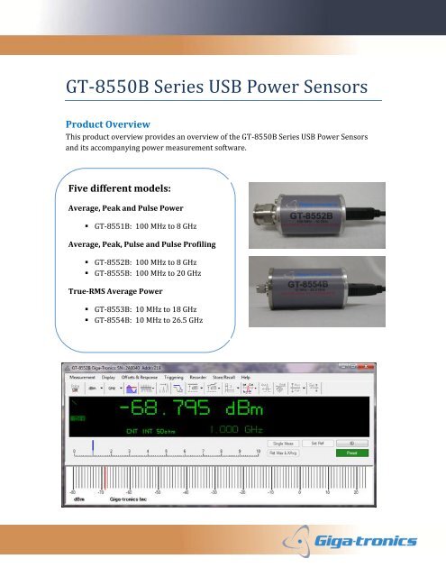
<strong>GT</strong>-<strong>8550B</strong> Series <strong>USB</strong> <strong>Power</strong> <strong>Sensors</strong>Product <strong>Overview</strong>This product overview provides an overview of the <strong>GT</strong>-<strong>8550B</strong> Series <strong>USB</strong> <strong>Power</strong> <strong>Sensors</strong>and its accompanying power measurement software.Five different models:Average, Peak and Pulse <strong>Power</strong>• <strong>GT</strong>-8551B: 100 MHz to 8 GHzAverage, Peak, Pulse and Pulse Profiling• <strong>GT</strong>-8552B: 100 MHz to 8 GHz• <strong>GT</strong>-8555B: 100 MHz to 20 GHzTrue-RMS Average <strong>Power</strong>• <strong>GT</strong>-8553B: 10 MHz to 18 GHz• <strong>GT</strong>-8554B: 10 MHz to 26.5 GHz
IntroductionThis product overview provides a detailed description of the features and capabilities of the<strong>GT</strong>-<strong>8550B</strong> <strong>USB</strong> <strong>Power</strong> <strong>Sensors</strong> and its accompanying software. The overview is intended togive engineers & technicians a high level understanding of what the product is and how itworks. In addition, the different model numbers are compared to enable you to select thebest model to fit your application needs.Key Features SummaryHardware FeaturesFrequency range: 10 MHz up to 26.5 GHz<strong>Power</strong> range: -60 dBm up to +20 dBmTrue-RMS average power (<strong>GT</strong>-8553B and <strong>GT</strong>-8554B)Video (modulation) bandwidth: Up to 10 MHz• Measure wireless communication signals• Measure pulse widths as narrow as 325 nsMake measurements fast: Up to 2000 measurements per secondEasy to use software comes free with all <strong>USB</strong> <strong>Power</strong> <strong>Sensors</strong>• Use in ATE environment by using the dynamic link libraries (DLL)No need to ever zero or make a front panel power calibration• No downtime related to zeroing or for a front panel calibration• Useful in remote monitoring applicationsInternal and external triggeringSoftware FeaturesPulse Profiling Mode (power versus time graph) – (<strong>GT</strong>-8552B and <strong>GT</strong>-8555B)• Time gated measurements: Peak <strong>Power</strong>, Average <strong>Power</strong>, Crest Factor, Droop,Overshoot, Rise Time, Fall Time, Duty Cycle, Pulse Repetition Frequency (PRF),Pulse Repetition Interval (PRI) and Pulse Width Pulse measurements – (<strong>GT</strong>-8551B, <strong>GT</strong>-8552B and <strong>GT</strong>-8555B)• <strong>Power</strong> meter display that provides quick measurements of parameters such as:peak and pulse power, average power, min and max power and duty cycle Relative and Offset power, and Pass/Fail limit mode Strip Chart – Data Logger <strong>Power</strong> Statistics Chart – (<strong>GT</strong>-8552B and <strong>GT</strong>-8555B)ApplicationsRadarWireless CommunicationsField test, R&D, and maintenanceComponent testAN -<strong>GT</strong>122C (Rev 11-12-2012) <strong>GT</strong>-<strong>8550B</strong> Series <strong>USB</strong> <strong>Power</strong> <strong>Sensors</strong> Product Ov erv iew Page 2 of 11©Copy right 2012 <strong>Giga</strong>-<strong>tronics</strong> Incorporated. All rights reserv ed.
Six Different <strong>USB</strong> <strong>Power</strong> Sensor ModelsThe <strong>GT</strong>-<strong>8550B</strong> series consist of six different model numbers. See Table 1. The <strong>GT</strong>-8551B, <strong>GT</strong>-8552Band <strong>GT</strong>-8555B can measure average, peak and pulse power. The <strong>GT</strong>-8552B and <strong>GT</strong>-8555B providepulse profiling capability. The <strong>GT</strong>-8553B and <strong>GT</strong>-8554B measure CW signals (average power) only.Table 1: <strong>GT</strong>-<strong>8550B</strong> Series <strong>USB</strong> <strong>Power</strong> <strong>Sensors</strong> Model Number ComparisonParameterFrequencyRangeSensor Model<strong>GT</strong>-8551B <strong>GT</strong>-8552B <strong>GT</strong>-8553B <strong>GT</strong>-8554B <strong>GT</strong>-8555B0.1 to 8 GHz 1 0.1 to 8 GHz 1 0.01 to 18 GHz0.01 to 26.5GHz0.1 to 20 GHz<strong>Power</strong> Range -60 to +20 dBm -60 to +20 dBm -50 to +20 dBm -50 to +20 dBm -40 to +20 dBm<strong>Power</strong>MeasurementsMeasurementModesTime GatedMeasurementsOtherMeasurementsTypes ofSignalsMeasuredVideoBandwidthTriggeringCapabilitiesAverage, Pulse,Peak, CrestFactor, Min, Maxand Duty CycleCW, Peak &PulseNoneStrip ChartCW, Modulated,Burst & Pulsed10 MHzAverage, Pulse ,Peak, CrestFactor, Min, Maxand Duty CycleCW, Peak & PulseProfilingPulse Profiling:plot power vs.time and measurethe followingparameters: Rise& Fall Time, DutyCycle, PulseRepetitionFrequency, PulseRepetitionInterval, PulseWidth, Droop andOvershoot<strong>Power</strong> Statistics(PDF, CDF, CCDF),Strip ChartCW, Modulated,Burst & Pulsed10 MHz(pulse widthsdown to 325 ns)True-RMSAverage, Min &MaxCWTrue-RMSAverage, Min &MaxCWAverage, Pulse ,Peak, CrestFactor, Min, Maxand Duty CycleCW, Peak & PulseProfilingNone None Pulse Profiling:plot power vs.time andmeasure thefollowingparameters:Rise & Fall Time,Duty Cycle, PulseRepetitionFrequency, PulseRepetitionInterval, PulseWidth, Droop andOvershootStrip Chart Strip Chart <strong>Power</strong> Statistics(PDF, CDF,CCDF), StripChartCWCW100 Hz 100 HzNo Yes No No YesCW, Modulated,Burst & Pulsed10 MHz(pulse widthsdown to 325 ns)AN-<strong>GT</strong>122C (Rev 11-12-2012) <strong>GT</strong>-<strong>8550B</strong> Series <strong>USB</strong> <strong>Power</strong> <strong>Sensors</strong> Product <strong>Overview</strong> Page 3 of 11©Copyright 2012 <strong>Giga</strong>-<strong>tronics</strong> Incorporated. All rights reserved.
<strong>GT</strong>-<strong>8550B</strong> Series <strong>USB</strong> <strong>Power</strong> Sensor SetupUsing the <strong>USB</strong> power sensor is very fast and easy. Simply connect a standard <strong>USB</strong> cable tothe sensor and connect the other end to the computer’s <strong>USB</strong> 2.0 or higher port. See figure 1.To connect multiple sensors, a <strong>USB</strong> self-powered hub may be required. Up to 12 powersensors can be connected.Figure 1: <strong>GT</strong>-<strong>8550B</strong> Series <strong>USB</strong> <strong>Power</strong> Sensor SetupThe computer provides all the power one sensor needs. The sensor measures the RF powerfrom the device under test, performs the necessary signal conditioning and converts thesignal to a digital format. The data is then transferred over the <strong>USB</strong> bus to the computer.The <strong>Giga</strong>-<strong>tronics</strong> software displays the measurement results.Unlike conventional bench-top power meters, power sensor combinations, there is no needto zero the sensor or calibrate the sensor to an external reference. Thus it is ideal for fieldportable measurements or remote monitoring applications.The <strong>Giga</strong>-<strong>tronics</strong> <strong>GT</strong>-<strong>8550B</strong> Series <strong>USB</strong> <strong>Power</strong> <strong>Sensors</strong> consist of five different modelnumbers. You can measure CW, average, pulse and peak power at a lower price versus thetraditional bench-top power meters and power sensor combinations.AN -<strong>GT</strong>122C (Rev 11-12-2012) <strong>GT</strong>-<strong>8550B</strong> Series <strong>USB</strong> <strong>Power</strong> <strong>Sensors</strong> Product Ov erv iew Page 4 of 11©Copy right 2012 <strong>Giga</strong>-<strong>tronics</strong> Incorporated. All rights reserv ed.
The <strong>Giga</strong>-<strong>tronics</strong> <strong>GT</strong>-<strong>8550B</strong> Series <strong>USB</strong> <strong>Power</strong> <strong>Sensors</strong> consist of five different modelnumbers. You can measure CW, average, pulse and peak power at a lower price versus thetraditional bench-top power meters and power sensor combinations.<strong>GT</strong>-<strong>8550B</strong> Series <strong>USB</strong> <strong>Power</strong> Sensor ConnectorsThe <strong>USB</strong> power sensor comes in a lightweight ruggedized case. See figure 2.<strong>USB</strong> PortFigure 2: <strong>GT</strong>-<strong>8550B</strong> Series connectionsTrigger InputSMB (f)On the back end of the sensor, an SMB female connector provides for a trigger input signal.Only the <strong>GT</strong>-8552B and <strong>GT</strong>-8555B models have triggering capabilities. A green LEDindicates the computer‘s connectivity status.Dimensions: <strong>GT</strong>-8551B, <strong>GT</strong>-8552B: 2” x 2.5” x 3” <strong>GT</strong>-8553B, <strong>GT</strong>-8554B and <strong>GT</strong>-8555B: 2” x 2.5” x 3.5”Weight: < 1 poundAN-<strong>GT</strong>122C (Rev 11-12-2012) <strong>GT</strong>-<strong>8550B</strong> Series <strong>USB</strong> <strong>Power</strong> <strong>Sensors</strong> Product <strong>Overview</strong> Page 5 of 11©Copyright 2012 <strong>Giga</strong>-<strong>tronics</strong> Incorporated. All rights reserved.
Measurement SoftwareAfter you connect the <strong>USB</strong> power sensor to the computer’s <strong>USB</strong> port, the software can beused to quickly and easily display the measured results. The software is a graphical userinterface that works with the <strong>GT</strong>-<strong>8550B</strong> series <strong>USB</strong> power sensors. It comes free with everypower sensor and may be downloaded from the <strong>Giga</strong>-<strong>tronics</strong> web site. It is compatible withthese operating systems: Microsoft® Windows XP, Vista (32) or Windows 7 (32 or 64).When the software is first launched, it automatically detects all the sensors that areconnected to the PC. The Connection Selection window shown in figure 3 below indicatesthat two <strong>USB</strong> power sensors are connected to the computer. Multiple sensors can beconnected to enable you to make multi-channel power measurements. Depending on theamount of sensors you want to connect, a <strong>USB</strong> hub may be required. Up to 12 sensors willbe recognized by the software.Figure 3: Sensor connection selection menu example for two sensorsAN -<strong>GT</strong>122C (Rev 11-12-2012) <strong>GT</strong>-<strong>8550B</strong> Series <strong>USB</strong> <strong>Power</strong> <strong>Sensors</strong> Product Ov erv iew Page 6 of 11©Copy right 2012 <strong>Giga</strong>-<strong>tronics</strong> Incorporated. All rights reserv ed.
Measurement ModesCW Measurement ModeIn CW (continuous wave) mode, the instantaneous average and minimum and maximumaverage power is measured and displayed. When the CW measurement mode is selected,the CW power meter panel is displayed. See figure 4. CW measurement mode is availableon all models of power sensors. This mode is recommended for measuring signals that arenot burst or pulsed and have no amplitude modulation.Figure 4: Measurement displays for <strong>GT</strong>-8552B in CW mode and <strong>GT</strong>-8554B (CW only)AN -<strong>GT</strong>122C (Rev 11-12-2012) <strong>GT</strong>-<strong>8550B</strong> Series <strong>USB</strong> <strong>Power</strong> <strong>Sensors</strong> Product Ov erv iew Page 7 of 11©Copy right 2012 <strong>Giga</strong>-<strong>tronics</strong> Incorporated. All rights reserv ed.
In CW mode, a number of functions can be controlled:Display units: dBm, dBW, dBkW, dBuV, dBmV, dBV, Watt and Volt (50 Ohm)Signal frequency (MHz or GHz)Averaging, extended averagingMax Hold, Pass/Fail LimitsRelative, Offset and Minimum Loss Pad (75 Ohm)Triggering: Internal, External, Single, ContinuousSave/Recall functionStrip Chart (Logger) functionPulse Measurement ModeThe <strong>GT</strong>-8552B and <strong>GT</strong>-8555B have a pulse measurement mode. In pulse measurementmode, the peak power is measured and displayed. See figure 5. In addition, the averagepower, duty cycle and crest factor are displayed.Figure 5: Pulse measurement mode displayAN -<strong>GT</strong>122C (Rev 11-12-2012) <strong>GT</strong>-<strong>8550B</strong> Series <strong>USB</strong> <strong>Power</strong> <strong>Sensors</strong> Product Ov erv iew Page 8 of 11©Copy right 2012 <strong>Giga</strong>-<strong>tronics</strong> Incorporated. All rights reserv ed.
Pulse Profiling Measurement ModeWith the <strong>GT</strong>-8552B and <strong>GT</strong>-8555B model power sensors, you also get the Pulse Profilingmeasurement mode. This mode enables you to display the RF power envelope versus time.See figure 6.Figure 6: Pulse Profiling measurement mode displays power versus timeIn this mode, you can make time gated measurements of such parameters as Peak <strong>Power</strong>,Average <strong>Power</strong>, Crest Factor, Droop, Overshoot, Rise Time, Fall Time, Duty Cycle, PulseRepetition Frequency (PRF), Pulse Repetition Interval (PRI) and Pulse Width. Up to 6 timegates and up to 10 markers can be set. In addition, you can add a marker to the trace tomake a measurement at a specific point or the difference between two points with a markerdelta measurement. You can also save traces to your hard drive and recall them at a latertime. Notice that in this example, one marker and a delta marker are set. The measurementparameters for each gate setting are for that particular gate time interval.AN -<strong>GT</strong>122C (Rev 11-12-2012) <strong>GT</strong>-<strong>8550B</strong> Series <strong>USB</strong> <strong>Power</strong> <strong>Sensors</strong> Product Ov erv iew Page 9 of 11©Copy right 2012 <strong>Giga</strong>-<strong>tronics</strong> Incorporated. All rights reserv ed.
Strip Chart (Logger)The Strip Chart (Logger) mode allows viewing varying power levels of a signal over a setperiod of time. This is feature is available on all models of sensors. The example shown infigure 7 displays the power measured on a CW signal over about 2 minutes duration.Figure 7: Strip Chart (Logger)Remote MonitoringThese small light weight power sensors are ideal for remote monitoring applications. <strong>USB</strong>data transfer rate capabilities limit the <strong>USB</strong> cable length to 5 meters, which prohibits longdistance remote monitoring. This limitation can be overcome by installing any generic lowcost <strong>USB</strong>-to-LAN hub converter at the measurement site along with the power sensors. Thisenables remote monitoring across great distances.AN -<strong>GT</strong>122C (Rev 11-12-2012) <strong>GT</strong>-<strong>8550B</strong> Series <strong>USB</strong> <strong>Power</strong> <strong>Sensors</strong> Product Ov erv iew Page 10 of 11©Copy right 2012 <strong>Giga</strong>-<strong>tronics</strong> Incorporated. All rights reserv ed.
For more information:More information about the <strong>USB</strong> <strong>Power</strong> <strong>Sensors</strong> may be found from our website:www.giga<strong>tronics</strong>.comData Sheets<strong>GT</strong>-8551B <strong>USB</strong> <strong>Power</strong> Sensor http://www.giga<strong>tronics</strong>.com/downloads/datasheets/<strong>GT</strong>-8551B-ds.pdf<strong>GT</strong>-8552B <strong>USB</strong> <strong>Power</strong> Sensor http://www.giga<strong>tronics</strong>.com/downloads/datasheets/<strong>GT</strong>-8552B-ds.pdf<strong>GT</strong>-8553B <strong>USB</strong> <strong>Power</strong> Sensor http://www.giga<strong>tronics</strong>.com/downloads/datasheets/<strong>GT</strong>-8553B-ds.pdf<strong>GT</strong>-8554B <strong>USB</strong> <strong>Power</strong> Sensor http://www.giga<strong>tronics</strong>.com/downloads/datasheets/<strong>GT</strong>-8554B-ds.pdf<strong>GT</strong>-8555B <strong>USB</strong> <strong>Power</strong> Sensor http://www.giga<strong>tronics</strong>.com/downloads/datasheets/<strong>GT</strong>-8555B-ds.pdfOperation Manual http://www.giga<strong>tronics</strong>.com/downloads/man/<strong>GT</strong>-<strong>8550B</strong>_OpManual.pdfInstallation Guide http://www.giga<strong>tronics</strong>.com/downloads/man/<strong>GT</strong>-<strong>8550B</strong>_QuickStartGuide.pdfProgramming Manual http://www.giga<strong>tronics</strong>.com/downloads/man/<strong>GT</strong>-<strong>8550B</strong>_ProgManual.pdfSecurity Instructions http://www.giga<strong>tronics</strong>.com/downloads/man/<strong>GT</strong>-<strong>8550B</strong>_AN-<strong>GT</strong>xxx.pdfAN -<strong>GT</strong>122C (Rev 11-12-2012) <strong>GT</strong>-<strong>8550B</strong> Series <strong>USB</strong> <strong>Power</strong> <strong>Sensors</strong> Product Ov erv iew Page 11 of 11©Copy right 2012 <strong>Giga</strong>-<strong>tronics</strong> Incorporated. All rights reserv ed.


