INSTALLATION INSTRUCTIONS - Desa
INSTALLATION INSTRUCTIONS - Desa INSTALLATION INSTRUCTIONS - Desa
A gas line may be installed for the purpose of installing avented or vent-free gas appliance available through your localdistributor. Use a ½” black iron pipe and appropriate fittings.When installing a gas line, a shut-off valve designed forinstallation outside the appliance is recommended.STEP 1: To install, remove the knockout indentation on thefirebrick wall located approximately 2 inches above therefractory hearth floor on the required side. The knockoutindentation must be firmly tapped with any solid object until itis released. Remove fragmented portions of refractory (seefigure 8).line if desired. Follow the manufacturer’s installationinstructions provided with the gas appliance.CAUTION: All gas piping and connections must betested for leaks after the installation is completed. Afterensuring that the gas valve is on, apply a soap and watersolution to all connections and joints. Bubbles formingshow a leak. Correct all leaks at once. DO NOT USE ANOPEN FLAME FOR LEAK TESTING AND DO NOTOPERATE ANY APPLIANCE IF A LEAK ISDETECTED.VENT-FREE GAS LOG INSTALLATION:If you wish to install an unvented gas log set, only unventedgas log sets, which have been found to comply with thestandard for unvented room heaters, ANS Z21.11.2, are to beinstalled in this fireplace.NOTE: A DESA hood must be installed when using anunvented gas log set (see accessories on page 11).Figure 8GAS LINE KNOCKOUTWARNING: Do not operate an unvented gas log set inthis fireplace with the chimney removed.VENTED GAS LOG INSTALLATION:STEP 2: Remove gas line cover plate on rear of fireplace andpull out insulation from gas line conduit sleeve. Saveinsulation for reuse.STEP 3: Run a ½” (I.D.) black iron gas line into the fireplacethrough the gas line conduit sleeve (if using a raised platform,add height). Provide sufficient gas line into fireplace chamberfor fitting connection (see figure 9).If you install a decorative gas appliance (vented gas log), thedecorative gas appliance must comply with the Standard forDecorative Gas Appliance for Installation in solid fuel burningfireplace, ANS Z21.60-1996, Z21.84 or RGA 2-72, and shallalso be installed in accordance with the National Fuel GasCode, ANS Z223.1-1996.WARNING: When using a decorative gas appliance,the damper must be removed or permanently locked in thefully opened position.COLD CLIMATE INSTALLATIONS:The following installation procedures are recommended wheninstalling a fireplace system in a cold climate area. Followingthese steps will aid in reducing cold air infiltration from thefireplace enclosure into living space.Figure 9GAS LINE INSTALLATIONNOTE: Secure incoming gas line to wood framing to providerigidity for threaded end.STEP 4: Repack insulation around gas line and into sleeveopening. Seal any gaps between gas line and refractoryknockout hole with refractory cement or commercial furnacecement. Install the decorative gas appliance or cap-off gas1. The fireplace must be placed on a solid continuoussurface. You should insulate under the fireplace in allcold climate areas.2. In the case of a raised platform or cantilevered chase, youshould insulate under the structure to reduce airinfiltration.3. Insulate the walls of the chase, both on the outer andinterior partitioning wall (see figure 10). Clearances frompipe to insulating materials must be maintained.4. Using a firestop spacer in the chase at the ceiling level isrecommended for safety and reducing cold air movement(see accessories on page 11).5 For more information, visit www.desatech.com
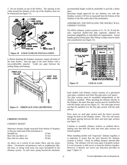
5. Do not insulate on top of the firebox. The opening in thecollar around the chimney at the top of the fireplace must notbe obstructed (see figure 11).recommended height would be preferable to provide a betterdraw.Maximum height approved for any chimney run with thisfireplace system is 60 feet as measured from the bottom of thefireplace to the flue outlet-end of the termination.ASSEMBLING AND INSTALLING THE DOUBLE WALLCHIMNEY SYSTEMThe DESA chimney system consists of 12, 18, 24, 36 and 48-inch, snap-lock double-wall pipe segments, planned formaximum adaptability to individual site requirements. Actuallengths gained (lineal gain) after fitting overlaps must be takeninto consideration (see figure 12).Figure 10 COLD CLIMATE INSTALLATION6. Before finishing the fireplace enclosure, inspect all joints ofthe outer firebox. Seal any gaps of the outer firebox with anon-combustible material. Caulk any gaps between thenailing flange and framing.Figure 12LINEAL GAINFigure 11 FIREPLACE COLLAR OPENINGCHIMNEY SYSTEM:CHIMNEY HEIGHTMinimum chimney height measured from bottom of fireplaceto flue gas outlet-end of the termination is:Straight run16 feetRun with one elbow set16 feetRun with two elbow sets30 feetAn elbow set is consist of one starter elbow and one returnelbow. Uncommon circumstances such as neighboring hills,tall trees, or strong wind areas can cause downdrafts in thechimney system. In such cases, going beyond the minimumEach double wall chimney section consists of a galvanizedouter pipe, a stainless steel inner flue pipe and a wire spacer.The pipe sections must be assembled independently as thechimney is installed. When attaching the chimney directly tothe fireplace, the inner flue pipe section must be installed firstwith the female side up (see figure 12). The outer pipe sectioncan then be installed over the flue pipe section with the maleend up.Press down on each pipe section until the lances securelyengage the hem on the fireplace starter. The wire will assurethe proper spacing between the inner and outer pipe sections(see figure 12).Continue to assemble chimney sections as outlined above,making sure that both the inner and outer pipe sections arelocked together.When installing double wall “snap-lock” chimney together, itis important to insure that the joint between the chimneysections is locked. Check by pulling chimney upward afterlocking. The chimney will not come apart if properly locked.It is not necessary to add screws to keep the chimney together.However, if desired, use screws per directions provided onpage 7, figure 14.6 For more information, visit www.desatech.com
- Page 3 and 4: GLOSSARY:WARNING: SAFETY INFORMATIO
- Page 5: HEARTH EXTENSION:A hearth extension
- Page 9 and 10: PENETRATING THE ROOF:To maintain a
- Page 12: REPLACEMENT PARTS(CONTACT YOUR LOCA
5. Do not insulate on top of the firebox. The opening in thecollar around the chimney at the top of the fireplace must notbe obstructed (see figure 11).recommended height would be preferable to provide a betterdraw.Maximum height approved for any chimney run with thisfireplace system is 60 feet as measured from the bottom of thefireplace to the flue outlet-end of the termination.ASSEMBLING AND INSTALLING THE DOUBLE WALLCHIMNEY SYSTEMThe DESA chimney system consists of 12, 18, 24, 36 and 48-inch, snap-lock double-wall pipe segments, planned formaximum adaptability to individual site requirements. Actuallengths gained (lineal gain) after fitting overlaps must be takeninto consideration (see figure 12).Figure 10 COLD CLIMATE <strong>INSTALLATION</strong>6. Before finishing the fireplace enclosure, inspect all joints ofthe outer firebox. Seal any gaps of the outer firebox with anon-combustible material. Caulk any gaps between thenailing flange and framing.Figure 12LINEAL GAINFigure 11 FIREPLACE COLLAR OPENINGCHIMNEY SYSTEM:CHIMNEY HEIGHTMinimum chimney height measured from bottom of fireplaceto flue gas outlet-end of the termination is:Straight run16 feetRun with one elbow set16 feetRun with two elbow sets30 feetAn elbow set is consist of one starter elbow and one returnelbow. Uncommon circumstances such as neighboring hills,tall trees, or strong wind areas can cause downdrafts in thechimney system. In such cases, going beyond the minimumEach double wall chimney section consists of a galvanizedouter pipe, a stainless steel inner flue pipe and a wire spacer.The pipe sections must be assembled independently as thechimney is installed. When attaching the chimney directly tothe fireplace, the inner flue pipe section must be installed firstwith the female side up (see figure 12). The outer pipe sectioncan then be installed over the flue pipe section with the maleend up.Press down on each pipe section until the lances securelyengage the hem on the fireplace starter. The wire will assurethe proper spacing between the inner and outer pipe sections(see figure 12).Continue to assemble chimney sections as outlined above,making sure that both the inner and outer pipe sections arelocked together.When installing double wall “snap-lock” chimney together, itis important to insure that the joint between the chimneysections is locked. Check by pulling chimney upward afterlocking. The chimney will not come apart if properly locked.It is not necessary to add screws to keep the chimney together.However, if desired, use screws per directions provided onpage 7, figure 14.6 For more information, visit www.desatech.com


