USAGE STRUCTURE AND DESIGN MG-1000-EEx ... - Micatrone
USAGE STRUCTURE AND DESIGN MG-1000-EEx ... - Micatrone
USAGE STRUCTURE AND DESIGN MG-1000-EEx ... - Micatrone
- No tags were found...

You also want an ePaper? Increase the reach of your titles
YUMPU automatically turns print PDFs into web optimized ePapers that Google loves.
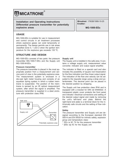
Installation and Operating InstructionsDifferential pressure transmitter for potentiallyexplosive areasMimablad: 176GB/1999-10-25Ersätter:<strong>MG</strong>-<strong>1000</strong>-<strong>EEx</strong><strong>USAGE</strong><strong>MG</strong>-<strong>1000</strong>-<strong>EEx</strong> is suitable for use in measurementand control circuits in air treatment processeswhere explosive gases can exist temporarily orpermanently. The design permits use in risk areasclassified Zone 0, 1 and 2 when the ignition temperaturefor the explosive gas exceeds 135 ºC.<strong>STRUCTURE</strong> <strong>AND</strong> <strong>DESIGN</strong><strong>MG</strong>-<strong>1000</strong>-<strong>EEx</strong> consists of two parts: the pressuretransmitter <strong>MG</strong>-<strong>1000</strong>-T-<strong>EEx</strong> and the Supply unit<strong>MG</strong>-<strong>1000</strong>-M-<strong>EEx</strong>.Pressure transmitterThe pressure transmitter is placed in the most appropriateposition from a measurement and servicepoint of view in the potentially explosive area.The measurement system is enclosed in adie-cast light metal housing and consists of anequalizer spring system in which a rubber membraneis suspended. The position of the membraneis sensed by an IR optical measurementsystem, after which the signal is amplified. Thepressure transmitter is supplied in a steel enclosurewith protection class IP66.Safe SäkertareaområdeMatningsdonSupply unitTransmitter Givare∆pPotentially Explosionsfarligt explosive område areaSupply unitThe Supply unit is installed in the safe area. It containsa voltage supply unit, measurement valueconverter, indicator and output signal amplifier.The indicator is fitted on a special card and alsoincludes the possibility of square root linearizationfor the flow indication and flow linear output signal.The indication of the flow and velocity can be adjustedto the requisite range using a strap and potentiometer.The decimal point can be placed inthe desired position by strapping.The Supply unit has protection class IP44 and isequipped with a bracket for DIN rail EN50022. Atransparent plastic cover protects the front paneland indicator. Electrical connections and setting ofthe desired output signal and made by removingthe unit’s left-hand end plate. Behind theright-hand end plate is a terminal block for the intrinsicallysafe circuits and the setting of flow indication.SafetyThe pressure transmitter and Supply unit are designedaccording to the European standard EN50014 and EN 50020 for intrinsic safety, explosiongroup and temperature class:* <strong>EEx</strong> ia IIC T4 for the pressure transmitter* [<strong>EEx</strong> ia] IIC for the Supply unit.
InstallationPressure transmitter1. Remove the cover from the enclosure.2. Install the enclosure vertically on, e.g. a wall inthe potentially explosive area. This is so thepressure measurement will be correct.3. The capacitance of the cable between thepressure transmitter and the Supply unit mustNOT exceed 38 nF (also see TECHNICALDATA).4. Strip the cable’s outer sheath so that the conductorsare approx. 10 cm long. Now insert thecable through the cable gland.5. Fold down the conductors in the centre of eachterminal and cut, strip and connect.6. Ensure the conductors are not strained andthen tighten the cable gland.7. Connect the enclosure to earth.Supply unit1. Fit the DIN rail in an appropriate position.Make sure there is sufficient space to removethe end plates with a screwdriver.2. Remove both end plates and push the Supplyunit onto the rail.3. Pull out the base plate and fit the cable glands.The holes not used should be plugged again.4. Strip the outer sheath on supply cable and thetransmitter cable so that the conductors areapprox. 20 cm long. Strip the outer sheath onthe output signal cable so that the conductorsare approx. 15 cm long.5. Insert the cables in the cable glands andtighten. Fold down the conductors 90º towardsthe base plate. Slide in the base plate in theslot and fold up the conductors towards theterminal block.6. Fold down the conductors in the centre of eachterminal and cut, strip and connect. The enclosureis earthed by clamping the earth conductorbetween the nut strips below the terminalon the left-hand side.Also refer to the Swedish electro technical standardSS 421 08 21 with regard to the installation.PRESSURE CONNECTIONThe pressure connection to the pressure transmittershould be made using <strong>Micatrone</strong>’s impulse linekit to obtain secure and sealed operation. (Datasheet MDS-1249/94).The measurement outlet is connected via an 8/6mm pneumatic HT plastic tube.* Positive pressure is connected to the + outlet.* Negative pressure is connected to the – outlet.When measuring the differential pressure the highestabsolute pressure is connected to the + outlet.NOTE! Outlets not used are left open to the atmosphere.
SETTING THE OUTPUT SIGNALSetting the output signal’s zero point1. Remove the left-hand end plate on the Supplyunit.2. Setting takes place using the no. 1 and no. 2dipswitches below the terminal block.No. 1 “ON” and no. 2 “OFF” gives 0…20 mA / 0…10 VNo. 1 “OFF” and no. 2 “ON” gives 4…20 mA / 2…10 VOUTPUT SIGNALOUTPUT SIGNALThe Supply unit is equipped with automatic switchingbetween current and voltage output signals.With loads less than 400 Ω a current output signalis given and with loads greater than 600 Ω a voltageoutput signal is given. However, due to theSupply unit’s inner resistance the load should exceed5k Ω with a voltage output signal. Avoid loadingthe output signal more than 400 Ω if a currentoutput signal is required.The Supply unit can be blocked so that only thecurrent output signal is obtained. This takes placeby setting the dipswitch no. 3 in the “OFF” position.ZERO POINT CALIBRATION1. Before zero point calibration can take placethe Supply unit must be voltage fed and theend plates screwed on for at least 60 minutesto reach its working temperature.2. The output signal from the Supply unit is measuredusing an accurate digital volt/mA meter.3. Set the block valve to the calibration position.If there is no block valve remove the pressurehoses from the pressure transmitter.4. Adjust the zero point using the trimming potentiometeron the front of the pressure transmitter.Check that the Supply unit’s digital indicatorshows zero in the pressure indication position(switch on the front in the left-hand position).5. Reset the block valve (refit the hoses).MAINTENANCENormally the <strong>MG</strong>-<strong>1000</strong>-<strong>EEx</strong> requires no service,but we recommend that the zero point should bechecked annually.Pressure linear output signalAuto. switchingOnlyNo 4 and no 5 dipswitches are used internally bythe Supply unit and should be in the OFF position.Switching the output signal’s function1. Remove the right-hand end plate.2. Switching takes place with SW1 pos 5&6onthe Supply unit’s upper card.Circuit cardPos. 5 strapped gives pressurelinear output signalFlow linear output signal% of the pressurerangeCircuit cardPos. 6 strapped gives flow linearoutput signal% of the pressurerange
SETTING THE FLOW INDICATIONThe flow indication is set according to the selectedmeasurement element/measurement method. Theindicator’s decimal point is selected using SW1(placed on the upper card’s right-hand side in theSupply unit) pos. 1&2andtherange using pos. 3& 4. The flow indication is finely trimmed using potentiometerP4.To adjust: remove the enclosure’s right-hand endplate and set the straps as shown below.Placement of the decimal pointNo decimal pointCircuit card000 The strap placed acrosspos. 1 & 2.Decimal point after the first digitCircuit card0.00 The strap in pos. 2.Decimal point after the second digitCircuit card00.0 The strap in pos. 1.Adjusting the indication using potentiometer P4The adjustment ranges for P4 stated below applywhen the flow linear output signal is 50% (25% differentialpressure).Also refer to the diagram on the next page thatshows the indicator’s value as a function of theflow linear output signal at the 4 different ranges.Adjustment range 0...300Circuit card“BN”Strap across pos. 3 & 4 onthe lowest row closest to thecircuit cardAdjustment range 300...570Circuit card“B3"Pos. 3 strapped.Adjustment range 570...810Circuit card“B4"Pos. 4 strapped.Adjustment range 810...999Circuit card“BU” Strap across pos. 3 & 4on the upper row.Connect pressure to the pressure transmitter andread off the pressure on the Supply unit’s indicatorwith the switch on the front in the left-hand position(∆p).Now turn the switch to the right (V) and adjust thevalue using P4 on the right-hand side of the uppercard according to the value read off from the measurementstation’s diagram or the calculatedvalue.Formula for calculating the velocity and flow.v=K × ∆ mp m/sV=A× K × ∆pm 3 /smv = velocity in m/sK m = measurement probe’s flow constant∆p = differential pressure in PaV= flow in m 3 /sA = duct area in m 2Principle diagram of the Supply unit’s upper cardDigital indicatorTest outletduringmanufacturingand servicingSW1 Pinstrip forstrappingSwitch for the indicatorRight position – flowLeft position – pressureP4Potentiometerto adjust theflow indication
Display999800BUB4600B3400200BN10 20 3040Flödesutsignal (%)Flow linear output signal (%)Example:When the flow linear output signal is 65% (6.5 Volt with output signal 0-10 Volt) the indicator shall show44.0 m 3 /h. The strap shall then be placed in position 3 (“B3”).5060708090100TECHNICAL DATA, PRESSURE TRANSMITTERSupply voltage: 20 VDC (max 23,0 VDC) Protection class:IP66Highest power thatmay be applied:P i = 0,64 WEnclosurematerial:Powder coated sheet steelHighest current thatmay be applied:Internal inductance:Internal capacitance:Output signal:I i = 111 mAL i = NegligibleC i = 137 nF4...20 mA, R Lmax = 500 ΩColour:Electricalconnection:Pressureconnection:Dimensions:RAL 7032 (Beige)1 pc. PR 15.28/6 mm pneumatic hoseB x HxD=175x130x75mmAmbient temperature:Measurementrange:standardMeasurementrange:specialOverload:Underload:0...40 °C0...100 Pa0...200 Pa0...500 Pa0...1 kPa0...2 kPa0...5 kPaContact <strong>Micatrone</strong> for informationregarding available measuringranges(i.e -50...+50 Pa)Max 50 kPaMax 10 kPaWeight:1.6 kgMeasurement accuracy according to IEC 770Measurement < ± 0.8 % of the measurementerror:rangeHysteresis:Repeatability:Temperatureoperation:< ±1%ofthemeasurementrange< 0.2 % of the measurementrange< 0.05 % / °C
-6-TECHNICAL DATA, SUPPLY UNITSupply voltage:Power consumption:Output signal:pressure linearor flow linear(Electric isolationfrom supply voltage)Indication:Scales:Ambient temperature:Protection class:230 ± 20 VAC 50/60 HzMax 8 VA at230 VAC0...20 mA, R Lmax = 400 Ω4...20 mA, R Lmax = 400 Ω0...10 Volt, R i =28Ω2...10 Volt, R i =28ΩPressure, flow or velocity with3 digitsPa, kPa, m/s, m 3 /s, m 3 /h or l/s0...40 °CIP44Accuracy range according to IEC 770The measuring accuracy for the pressure transmitter(<strong>MG</strong>-<strong>1000</strong>-T-<strong>EEx</strong>) is included in the following values:Measurementerror:Pressure linearoutput signalMeasurementerror:Flow linear outputsignalHysteresis:Repeatability:Temperatureoperation: