Communications I Dr. Mohammed Hawa Introduction to Digital - FET
Communications I Dr. Mohammed Hawa Introduction to Digital - FET Communications I Dr. Mohammed Hawa Introduction to Digital - FET
8. M-ary CodingAll the line coding schemes discussed above are called binary codes, since thenumber of bits per second is identical to the number of symbols per second (calledbaud rate). We say that for binary signaling:f0, data bit rate [in units of bit/s] = fsymb, symbol rate [in units of baud]Notice that a symbol is defined as a waveform pattern that the line code has for acertain period of time before switching to another waveform pattern (i.e., anothersymbol).In M-ary signaling, on the other hand, a cluster of bits is grouped to represent onesymbol. For example, in the 4-ary (also called Quaternary) case, two bits are groupedinto one symbol. The two bits can be in one of 4 possible states, which means that thesymbol can take M=4 different symbols. The following table shows a possiblemapping of two bit values to four symbols of a Quaternary signal. Thecorresponding line code for this Quaternary signal representing the bit stream1110110001001 is shown next.Bits Symbol00 -5 V01 -10 V10 5 V11 10 VM=4levelsClockData10 V1 1 1 0 1 1 0 0 0 1 0 0 15 VCode-5 V0-10 VT 0 Bit TimeT symb Symbol TimeT sSampling Time (assuming 8 bits per sample)Quaternary CodeNotice that a symbol time Tsymb is now twice the bit time T0. This means that there arehalf as much symbol transitions as there are bit transitions. We can say that:symbol rate [in units of baud] = (½) × data bit rate [in units of bit/s]For a general M-ary line coding scheme, we have:symbol rate [in units of baud] = (1/log2 (M)) × data bit rate [in units of bit/s]16
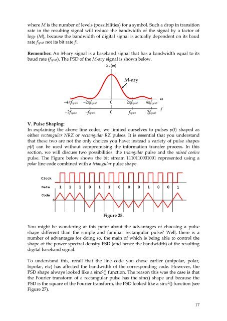
where M is the number of levels (possibilities) for a symbol. Such a drop in transitionrate in the resulting signal will reduce the bandwidth of the signal by a factor oflog2 (M), because the bandwidth of digital signal is actually dependent on its baudrate fsymb not its bit rate f0.Remember: An M-ary signal is a baseband signal that has a bandwidth equal to itsbaud rate (fsymb). The PSD of the M-ary signal is shown below.S m (w)M-ary-4pf symb -2pf symb02pf symb 4pf symbf-2f symb 0-f symbf symb2f symbwV. Pulse Shaping:In explaining the above line codes, we limited ourselves to pulses p(t) shaped aseither rectangular NRZ or rectangular RZ pulses. It is essential that you understandthat these two are not the only choices you have; instead a variety of pulse shapesp(t) can be used without compromising the information transfer process. In thissection, we will discuss two possibilities: the triangular pulse and the raised cosinepulse. The Figure below shows the bit stream 1110110001001 represented using apolar line code combined with a triangular pulse shape.ClockData 1 1 1 0 1 1 0 0 0 1 0 0 1Code0Figure 25.You might be wondering at this point about the advantages of choosing a pulseshape different than the simple and familiar rectangular pulse? Well, there is anumber of advantages for doing so, the main of which is being able to control theshape of the power spectral density PSD (and hence the bandwidth) of the resultingdigital baseband signal.To understand this, recall that the line code you chose earlier (unipolar, polar,bipolar, etc) has affected the bandwidth of the corresponding code. However, thePSD shape always looked like a sinc 2 () function. The reason this was the case is thatthe Fourier transform of a rectangular pulse has the sinc() shape and because thePSD is the square of the Fourier transform, the PSD looked like a sinc 2 () function (seeFigure 27).17
- Page 1 and 2: EE 421: Communications IDr. Mohamme
- Page 4 and 5: impulses, as shown in Figure 4 belo
- Page 6 and 7: In voice telephony, for example, th
- Page 8 and 9: clocking is important in digital sy
- Page 10 and 11: Polar NRZ CodePolar RZ CodeIn addit
- Page 12 and 13: Bipolar (AMI) CodeThe alternating c
- Page 14 and 15: MLT-3 Code7. Manchester:There are t
- Page 18 and 19: You also recall that using a RZ rec
- Page 20: An example of using the raised-cosi
where M is the number of levels (possibilities) for a symbol. Such a drop in transitionrate in the resulting signal will reduce the bandwidth of the signal by a fac<strong>to</strong>r oflog2 (M), because the bandwidth of digital signal is actually dependent on its baudrate fsymb not its bit rate f0.Remember: An M-ary signal is a baseband signal that has a bandwidth equal <strong>to</strong> itsbaud rate (fsymb). The PSD of the M-ary signal is shown below.S m (w)M-ary-4pf symb -2pf symb02pf symb 4pf symbf-2f symb 0-f symbf symb2f symbwV. Pulse Shaping:In explaining the above line codes, we limited ourselves <strong>to</strong> pulses p(t) shaped aseither rectangular NRZ or rectangular RZ pulses. It is essential that you understandthat these two are not the only choices you have; instead a variety of pulse shapesp(t) can be used without compromising the information transfer process. In thissection, we will discuss two possibilities: the triangular pulse and the raised cosinepulse. The Figure below shows the bit stream 1110110001001 represented using apolar line code combined with a triangular pulse shape.ClockData 1 1 1 0 1 1 0 0 0 1 0 0 1Code0Figure 25.You might be wondering at this point about the advantages of choosing a pulseshape different than the simple and familiar rectangular pulse? Well, there is anumber of advantages for doing so, the main of which is being able <strong>to</strong> control theshape of the power spectral density PSD (and hence the bandwidth) of the resultingdigital baseband signal.To understand this, recall that the line code you chose earlier (unipolar, polar,bipolar, etc) has affected the bandwidth of the corresponding code. However, thePSD shape always looked like a sinc 2 () function. The reason this was the case is thatthe Fourier transform of a rectangular pulse has the sinc() shape and because thePSD is the square of the Fourier transform, the PSD looked like a sinc 2 () function (seeFigure 27).17


